director data monitoring switch - wikileaks · data monitoring switch ... analyzer 2 analyzer 1...
TRANSCRIPT
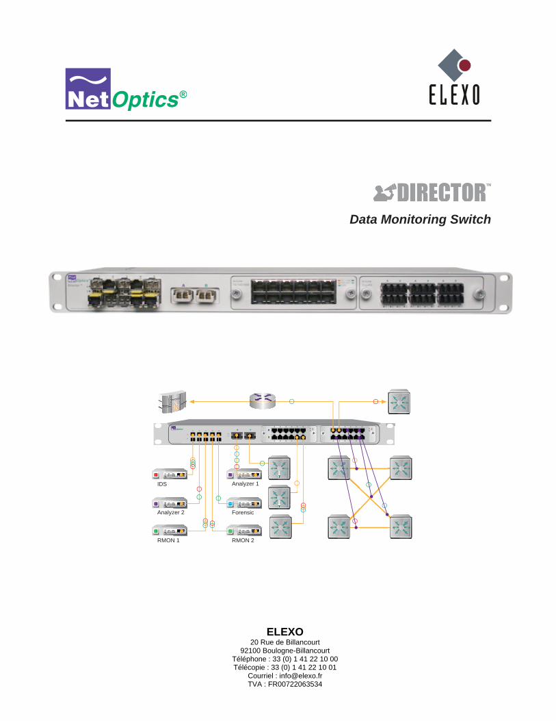
Data Monitoring Switch
www.netoptics.com
1
2B
A
A B
IDS
Analyzer 2
Analyzer 1
RMON 1 RMON 2
Forensic
ELEXO20 Rue de Billancourt
92100 Boulogne-BillancourtTéléphone : 33 (0) 1 41 22 10 00Télécopie : 33 (0) 1 41 22 10 01
Courriel : [email protected] : FR00722063534

Director
Content
Key Features . . . . . . . . . . . . . . . . . . . . . . . . . . . . . . . . . . . . . . . . . . . . . . . . . . . . . . . . . . . . . . . . . . . . . . . . . . . . 2
Director Part Numbers . . . . . . . . . . . . . . . . . . . . . . . . . . . . . . . . . . . . . . . . . . . . . . . . . . . . . . . . . . . . . . . . . . . . 3
Director Architecture . . . . . . . . . . . . . . . . . . . . . . . . . . . . . . . . . . . . . . . . . . . . . . . . . . . . . . . . . . . . . . . . . . . . . 4
USB port . . . . . . . . . . . . . . . . . . . . . . . . . . . . . . . . . . . . . . . . . . . . . . . . . . . . . . . . . . . . . . . . . . . . . . . . . . . . . . . 5
Director Management . . . . . . . . . . . . . . . . . . . . . . . . . . . . . . . . . . . . . . . . . . . . . . . . . . . . . . . . . . . . . . . . . . . . . 5
Typical Application . . . . . . . . . . . . . . . . . . . . . . . . . . . . . . . . . . . . . . . . . . . . . . . . . . . . . . . . . . . . . . . . . . . . . . . 6
In-line Monitoring of 10 Gigabit Links . . . . . . . . . . . . . . . . . . . . . . . . . . . . . . . . . . . . . . . . . . . . . . . . . . . . . . . 8
Director Front Panel . . . . . . . . . . . . . . . . . . . . . . . . . . . . . . . . . . . . . . . . . . . . . . . . . . . . . . . . . . . . . . . . . . . . . . 9
Director Rear Panel . . . . . . . . . . . . . . . . . . . . . . . . . . . . . . . . . . . . . . . . . . . . . . . . . . . . . . . . . . . . . . . . . . . . . . 10

Director
1
Introduction
Net Optics Director is a key component for building a comprehensive, consolidated monitoring infrastructure for both network management and security. It extends the range of visibility for data monitoring across converged data and digital voice networks, while eliminating monitoring port contention and minimizing the number of tools needed to optimally manage the network.
ports. It includes aggregation and regeneration functions, so the link-to-monitor-port mapping can be one-to-one,
particular monitoring tools.
Matrix switching, aggregation, and regeneration
provided. Network and Span ports can be aggregated and regenerated to output ports in almost any combination.
Modular design
Copper links.
The Director Chassis includes two DNM slots; they can be populated with the same or different DNM types.
Ten 1-Gigabit Monitor ports are SFP-based, accepting any mix of Copper, SX, and LX interface modules.
Flexible 10 Gigabit support
Monitor ports.
Expandable
Two 10 Gigabit ports on the rear of the unit enable daisy-chaining up to ten Director chassis to expand the number of

Director
2
Ease of Use
19-inch rack frame, 1U high
Front-mounted connectors for quick and easy installation
or it may be exported to a third party reporting tool such as a protocol analyzer
CLI also available remotely over secure SSH connection
Field-upgradeable software
Compatible with all major manufacturers’ monitoring devices, including protocol analyzers, probes, and intrusion detection and prevention systems
Monitor port Filtering
Filters based on IP protocol, IP addresses, layer 4 ports, MAC addresses, and VLANs
Source and destination MAC addresses, or ranges of addresses
Source and destination IP addresses, or ranges of addresses
Source and destination ports, or ranges of ports
Supports IPv4 and IPv6 protocols
VLAN
Passive, Secure Technology
Passive access at up to 10 Gbps
In-line links do not interfere with the data stream or introduce a point of failure
Redundant power to maximize uptime
In-line links default to open under a complete power-fail condition, ensuring network availability
Fully RoHS compliant
Unsurpassed Support
Net Optics offers technical support throughout the lifetime of your purchase. Our technical support team is
[email protected]. FAQs are also available on Net Optics Web site at www.netoptics.com.

Director
3
Director Part Numbers
Chassis Part Number Description
DIR-3400 Director Main Chassis with 10 SFP monitor ports
DIR-7400 Director Main Chassis with 10 SFP monitor ports, 2 XFP 10GbE ports, 2 XFP uplink ports
DNM Part Number Description
DNM-100 6-Port 10/100/1000 Copper In-Line Module
DNM-110 12-Port 10/100/1000 Copper Span Module
DNM-200 6-Port Gigabit SX Fiber 62.5µm In-Line Module
DNM-210 12-Port Gigabit SX Fiber 62.5µm Span Module
DNM-220 6-Port Gigabit SX Fiber 50µm In-Line Module
DNM-230 12-Port Gigabit SX Fiber 50µm Span Module
DNM-300 6-Port Gigabit LX Fiber In-Line Module
DNM-310 12-Port Gigabit LX Fiber Span Module
DNM-320 6-Port Gigabit ZX Fiber In-Line Module
DNM-330 12-Port Gigabit ZX Fiber Span Module

Director
4
Director ArchitectureThe following diagram shows a schematic view of the architecture of the Director device shown as a Matrix Switch with
Key: Network or Span port Monitor Port Aggregating switch conection
Dim Alternate configurations for 10 GbE XFP ports
DNM with6 in-line
network ports
DNM with12 Span or
out-of-bandnetwork ports
Four configurable10GbE XFP ports
10 SFP monitor ports
Filters
n2.5
n2.4
n2.3
n2.2
n2.1
n2.10
n2.9
n2.12
n2.11
n2.8
n2.7
n2.6
n1.1
n1.3
n1.5
n1.7
n1.9
n1.11
n1.2
n1.4
n1.6
n1.7
n1.10
n1.12
t1.1
t1.1
t2.2t2.1t1.2
t1.2
t2.1
t2.2
m.1 m.2 m.3 m.4 m.5 m.6 m.7 m.8 m.9 m.10
Director internal architectureFigure 1:
Director can be viewed as a matrix switch with up to 28 inputs, or Network ports, and 14 outputs, or Monitor ports.

Director
5
while Span DNM models support 12 Span ports. The diagram shows one in-line and one Span DNM. Both in-line and Span DNMs are available with either Copper or SX, LX, or ZX Fiber interfaces. Different DNM types can be mixed in the same chassis, for example, one in-line Copper DNM and one Span Fiber DNM. The modules are hot-pluggable for easy serviceability. One or both DNM slots can be populated. The DNM slots are numbered 1 for the slot on the left and 2 for the slot on the right. If only one slot is populated, it should be slot 1.
Both Span
Both Monitor
One Span and one Monitor
chassis for expansion.
A USB port located on the back is reserved for future functionality.
Director Management
administrators. The CLI runs locally over an RS-232 serial port or remotely over a secure SSH connection.
Web ManagerSystem Manager—An SNMP platform-based tool to mange all the Director and other Net Optics iTap-enabled devices on your network
Director
6
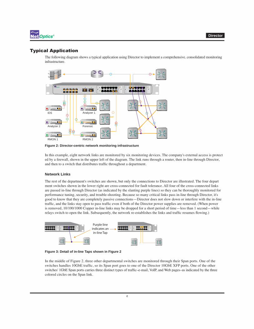
Typical ApplicationThe following diagram shows a typical application using Director to implement a comprehensive, consolidated monitoringinfrastructure.
www.netoptics.com
1
2B
A
A B
IDS
Analyzer 2
Analyzer 1
RMON 1 RMON 2
Forensic
Director-centric network monitoring infrastructureFigure 2:
-
Network Links
-ment switches shown in the lower right are cross-connected for fault tolerance. All four of the cross-connected links
good to know that they are completely passive connections—Director does not slow down or interfere with the in-line
Purple lineindicates anin-line Tap
Detail of in-line Taps shown in Figure 2Figure 3:
In the middle of Figure 2, three other departmental switches are monitored through their Span ports. One of the
colored circles on the Span link.

Director
7
In this installation, Director has ten additional Span ports and one in-line link that are available for expansion, when more links need to be monitored.
Monitoring Tools
Still referring to Figure 2, six monitoring tools are connected to Director. They include protocol and performance analyzers,
connected network links, and the connections can be switched easily, using the Director CLI, without ever moving a
One of the network monitoring tools is capable of handling more than 1 Gbps, so it is attached to a 10 Gigabit XFP
The two green RMON monitoring tools at the bottom are the same type of tool. Two identical tools provide the capabil-ity of monitoring a greater amount of data than a single tool can handle. Another reason to use identical monitoring
Director
8
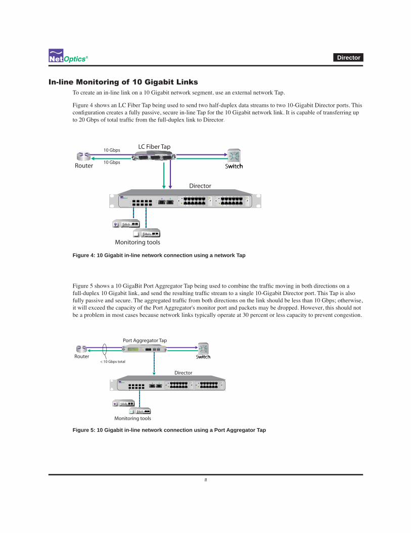
To create an in-line link on a 10 Gigabit network segment, use an external network Tap.
Figure 4 shows an LC Fiber Tap being used to send two half-duplex data streams to two 10-Gigabit Director ports. This
Director
LC Fiber Tap
Router Switch
Monitoring tools
10 Gbps
10 Gbps
www.netoptics.com
1
2B
A
A B
10 Gigabit in-line network connection using a network TapFigure 4:
be a problem in most cases because network links typically operate at 30 percent or less capacity to prevent congestion.
Director
Port Aggregator Tap
Router Switch
Monitoring tools
< 10 Gbps total
A B
10 Gigabit in-line network connection using a Port Aggregator TapFigure 5:
Director
9
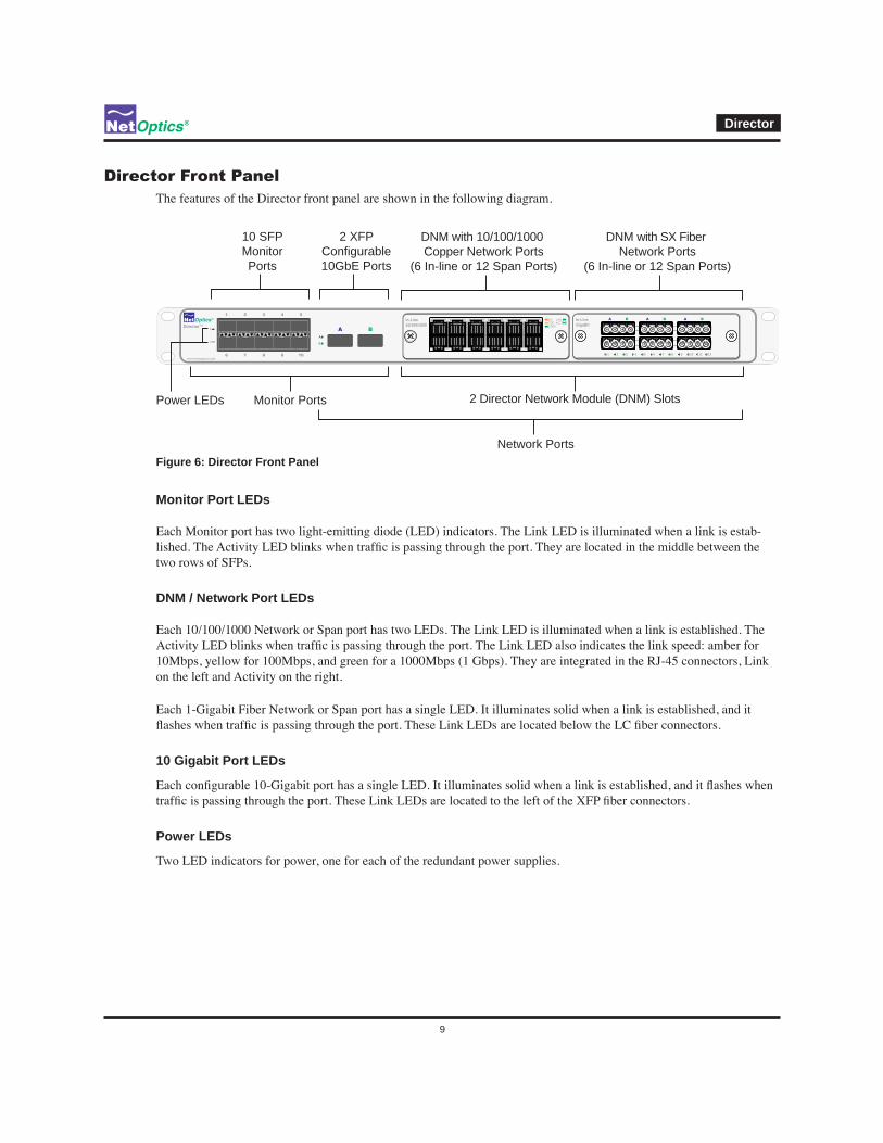
The features of the Director front panel are shown in the following diagram.
www.netoptics.com
™Director
1
2
B
A
1
6
2
7
3
8
5
10
4
9
A B
In-Line10/100/1000
101001000
LINKACT
In-LineGigaBit
1 2 3 4 5 6 7 8 9 10 11 12
A B A B A B
10 SFPMonitorPorts
2 XFPConfigurable10GbE Ports
2 Director Network Module (DNM) Slots
DNM with 10/100/1000 Copper Network Ports
(6 In-line or 12 Span Ports)
DNM with SX FiberNetwork Ports
(6 In-line or 12 Span Ports)
Monitor PortsPower LEDs
Network Ports
Director Front PanelFigure 6:
Monitor Port LEDs
-
two rows of SFPs.
DNM / Network Port LEDs
on the left and Activity on the right.
10 Gigabit Port LEDs
Power LEDs
Director
10
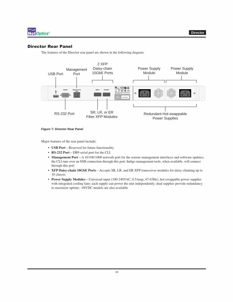
Director Rear PanelThe features of the Director rear panel are shown in the following diagram.
ManagementPort
RS232 INPUT OUTPUT
SERIALNUMBER XXXXXX
Power SupplyModule
ManagementPort
RS-232 Port
2 XFPDaisy-chain10GbE Ports
SR, LR, or ERFiber XFP Modules
Redundant Hot-swappablePower Supplies
USB Port
Power SupplyModule
Director Rear PanelFigure 7:
USB Port—Reserved for future functionality
RS-232 Port —DB9 serial port for the CLI
Management Portthe CLI runs over an SSH connection through this port; Indigo management tools, when available, will connect through this port
XFP Daisy-chain 10GbE Ports10 chassis
Power Supply Moduleswith integrated cooling fans; each supply can power the unit independently; dual supplies provide redundancy to maximize uptime; -48VDC models are also available