disassembling gearbox 2 wheels tractors and mowers · 2016-03-24 · disassembling gearbox 2 wheels...
TRANSCRIPT
Disassembling gearbox 2 Wheels Tractors and Mowers
1
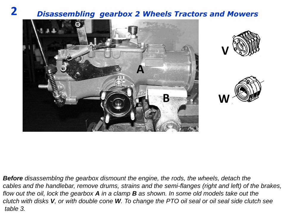
Before disassemblng the gearbox dismount the engine, the rods, the wheels, detach the
cables and the handlebar, remove drums, strains and the semi-flanges (right and left) of the brakes,
flow out the oil, lock the gearbox A in a clamp B as shown. In some old models take out the
clutch with disks V, or with double cone W. To change the PTO oil seal or oil seal side clutch see
table 3.
2
V
B
Disassembling gearbox 2 Wheels Tractors and Mowers
W
A
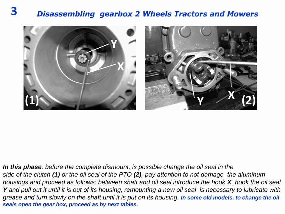
In this phase, before the complete dismount, is possible change the oil seal in the
side of the clutch (1) or the oil seal of the PTO (2), pay attention to not damage the aluminum
housings and proceed as follows: between shaft and oil seal introduce the hook X, hook the oil seal
Y and pull out it until it is out of its housing, remounting a new oil seal is necessary to lubricate with
grease and turn slowly on the shaft until it is put on its housing. In some old models, to change the oil
seals open the gear box, proceed as by next tables.
3
X
Disassembling gearbox 2 Wheels Tractors and Mowers
Y
X
Y (1) (2)
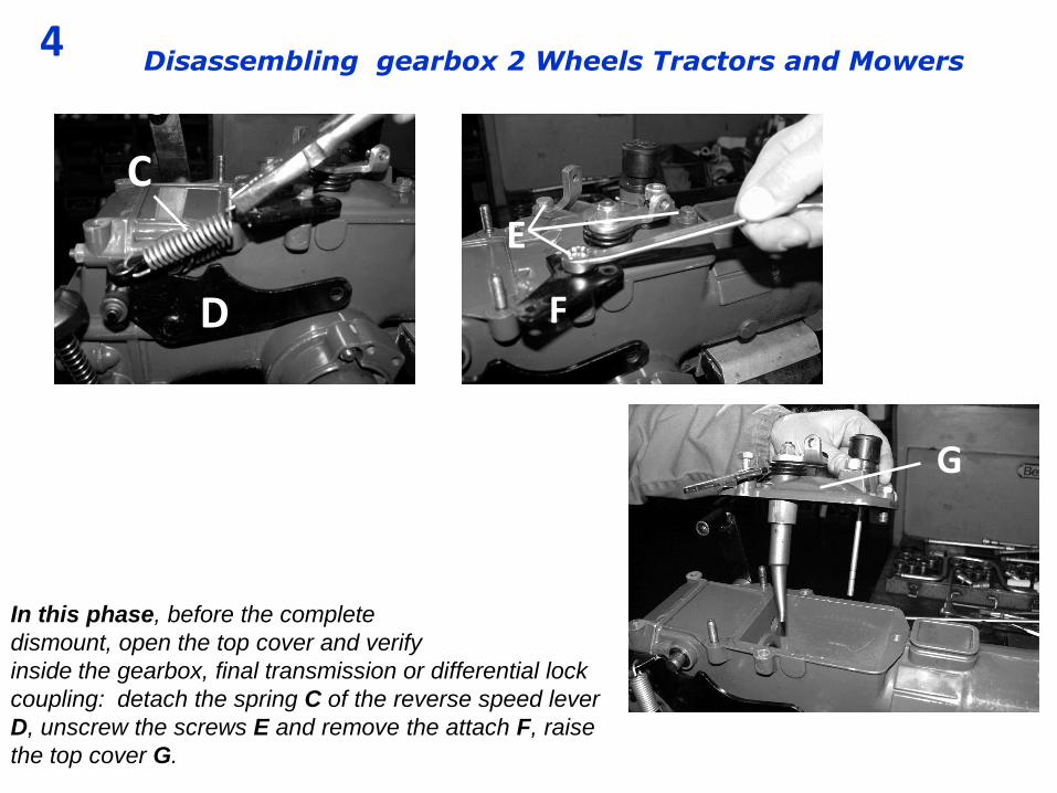
In this phase, before the complete
dismount, open the top cover and verify
inside the gearbox, final transmission or differential lock
coupling: detach the spring C of the reverse speed lever
D, unscrew the screws E and remove the attach F, raise
the top cover G.
4
C
E
Disassembling gearbox 2 Wheels Tractors and Mowers
G
F D

In this phase, before the complete dismount,
dismount the two semi-axles H (right and left), and
verify or change the components I, or change the oil seal of the
semi-axles as explained in the next table 6.
suggest to mark the position (J) with a marker
K, dismount the screws L and remove the semi-axle H.
5
H L
Disassembling gearbox 2 Wheels Tractors and Mowers
I
H (J)
K
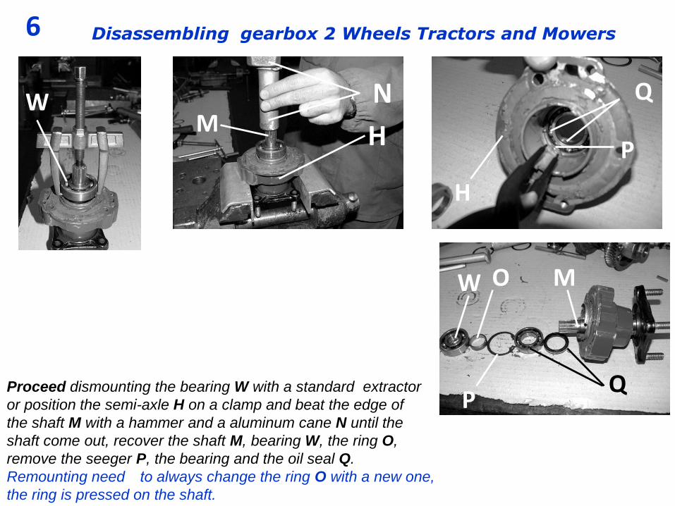
Proceed dismounting the bearing W with a standard extractor
or position the semi-axle H on a clamp and beat the edge of
the shaft M with a hammer and a aluminum cane N until the
shaft come out, recover the shaft M, bearing W, the ring O,
remove the seeger P, the bearing and the oil seal Q.
Remounting need to always change the ring O with a new one,
the ring is pressed on the shaft.
6
H P
Disassembling gearbox 2 Wheels Tractors and Mowers
Q
H
M N
M O
Q
P
W
W

If necessary to dismount the PTO lever R take out the pin
R1, to open the gearbox proceed as follows: Take out the
nuts S and screws T and remove the round cover U. In some
models the cover U is also the support of the reverse gear.
7
S
Disassembling gearbox 2 Wheels Tractors and Mowers
F
R
U
T
R1

Open the PTO cover L as by arrow, if the cover allos. With the
aid of a pin driver M remove the small bearing N from the PTO shaft, now is
possible to extract the cover L.
8 Disassembling gearbox 2 Wheels Tractors and Mowers
L
N
M L
N
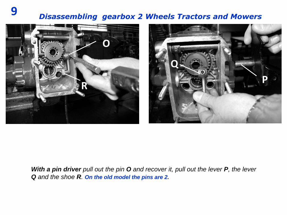
With a pin driver pull out the pin O and recover it, pull out the lever P, the lever
Q and the shoe R. On the old model the pins are 2.
9 Disassembling gearbox 2 Wheels Tractors and Mowers
P
O
Q
R
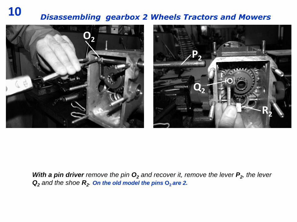
With a pin driver remove the pin O2 and recover it, remove the lever P2, the lever
Q2 and the shoe R2. On the old model the pins O2 are 2.
10 Disassembling gearbox 2 Wheels Tractors and Mowers
R2
O2
Q2
P2
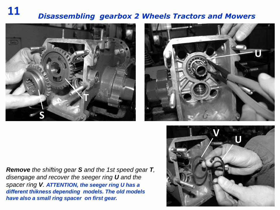
Remove the shifting gear S and the 1st speed gear T,
disengage and recover the seeger ring U and the
spacer ring V. ATTENTION, the seeger ring U has a
different thikness depending models. The old models
have also a small ring spacer on first gear.
11 Disassembling gearbox 2 Wheels Tractors and Mowers
V
S
U
T
U
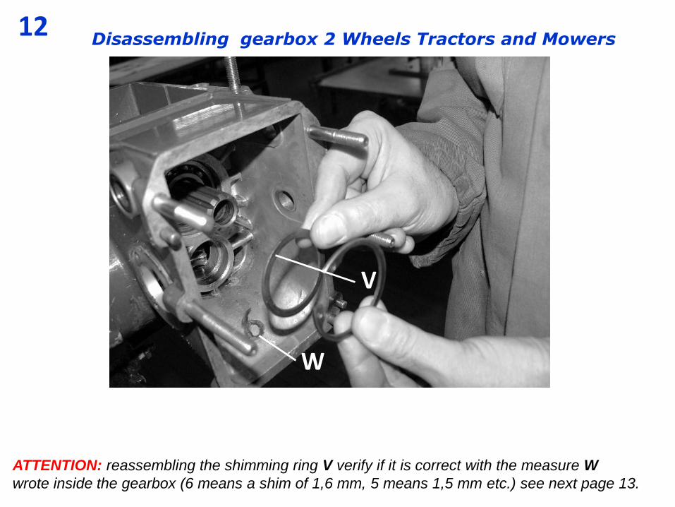
ATTENTION: reassembling the shimming ring V verify if it is correct with the measure W
wrote inside the gearbox (6 means a shim of 1,6 mm, 5 means 1,5 mm etc.) see next page 13.
12 Disassembling gearbox 2 Wheels Tractors and Mowers
W
V

The shimming rings V have different measures and code, they are inside the exploded tables of
the gearbox, it is important have an accurate shimming.
Attention: some gearboxes have thrust bearings Y mounted on the worm shaft Z, need to direct
the bearings as in figure below, the arrow means the direction of the load to determine the
orientation; “ g “ means the bigger side of the internal ring of the bearing.
13 Disassembling gearbox 2 Wheels Tractors and Mowers
U
V V
g
1 g
U
Y
Y
Z
X Attention: the seeger ring U could have different measure (2 or 2,5 mm), it depends by the housing where fitted.
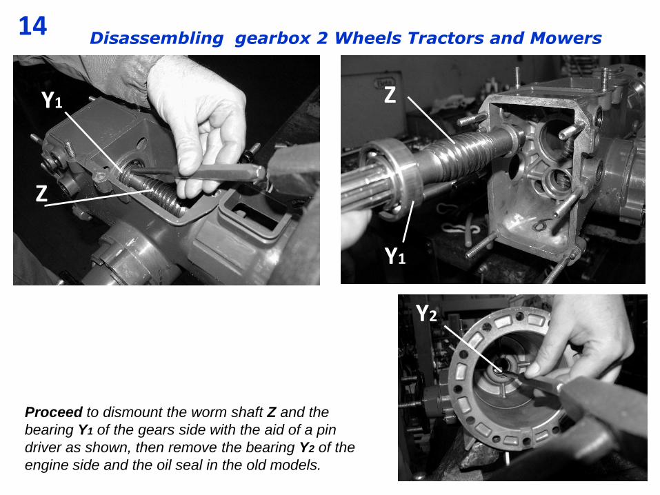
Proceed to dismount the worm shaft Z and the
bearing Y1 of the gears side with the aid of a pin
driver as shown, then remove the bearing Y2 of the
engine side and the oil seal in the old models.
14 Disassembling gearbox 2 Wheels Tractors and Mowers
Y1
Z
Y2
Z
Y1
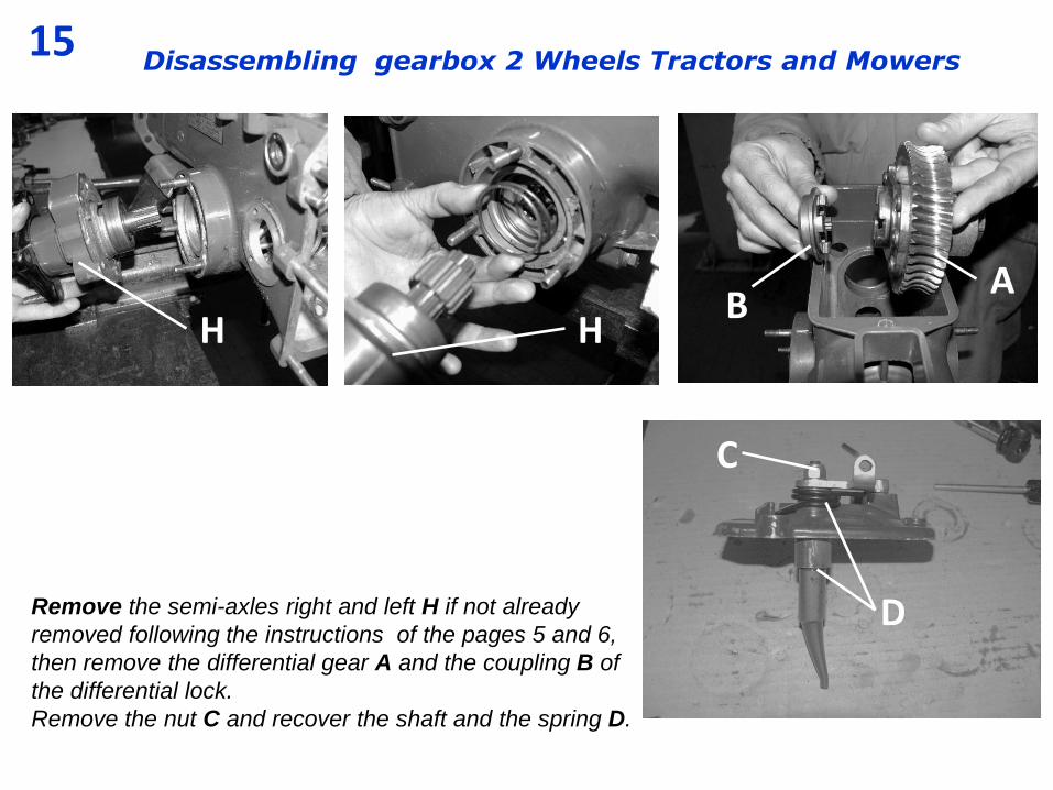
Remove the semi-axles right and left H if not already
removed following the instructions of the pages 5 and 6,
then remove the differential gear A and the coupling B of
the differential lock.
Remove the nut C and recover the shaft and the spring D.
15 Disassembling gearbox 2 Wheels Tractors and Mowers
B
A
H
C
D
H
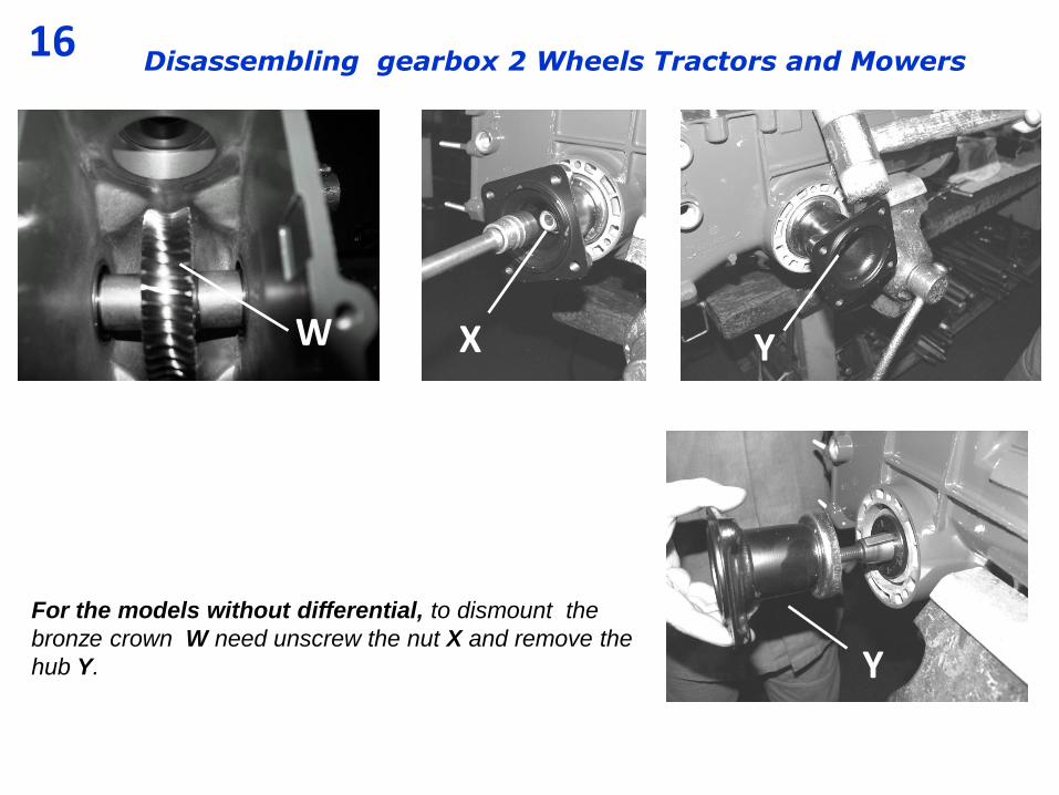
For the models without differential, to dismount the
bronze crown W need unscrew the nut X and remove the
hub Y.
16 Disassembling gearbox 2 Wheels Tractors and Mowers
X Y W
Y
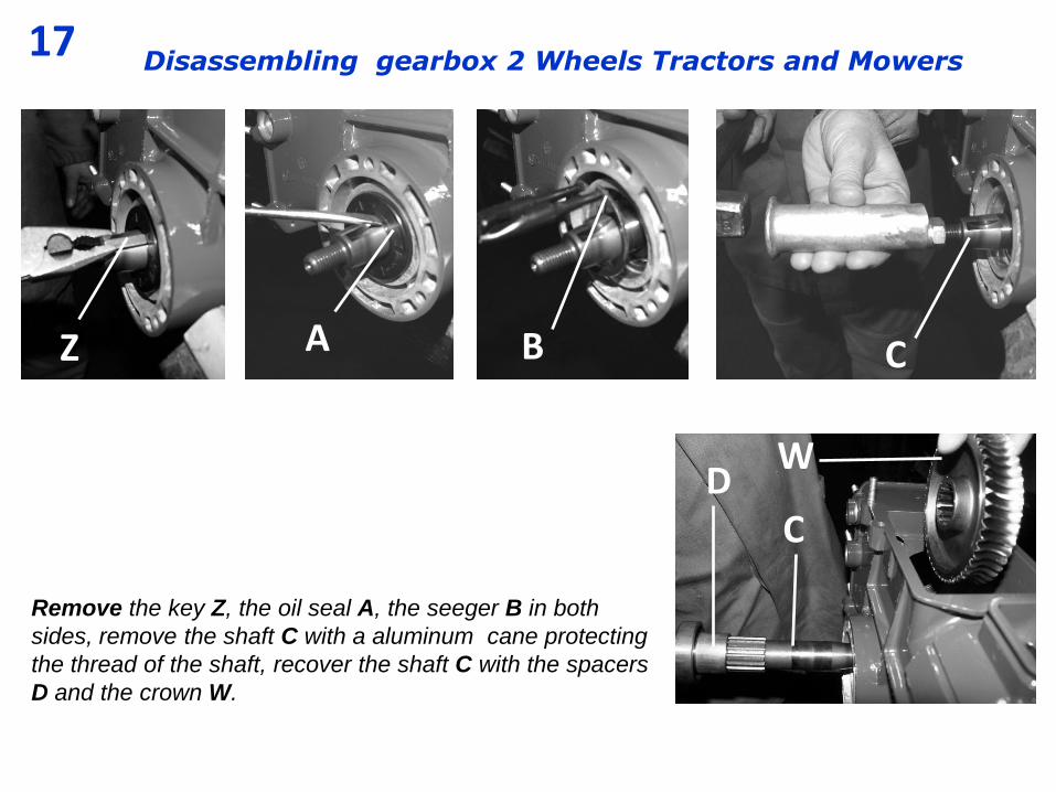
Remove the key Z, the oil seal A, the seeger B in both
sides, remove the shaft C with a aluminum cane protecting
the thread of the shaft, recover the shaft C with the spacers
D and the crown W.
17 Disassembling gearbox 2 Wheels Tractors and Mowers
A B Z
C
C
W D

Dismounting the PTO cover, put in the clamp the cover with
the 2 studs E protecting them with aluminum, Remove the
support of the reverse gear F, the gear G and the first shaft H
(shaft of the clutch). In the old models the gears G is complete
of the shaft J.
18 Disassembling gearbox 2 Wheels Tractors and Mowers
V U E
J
F
G
H

19 Disassembling gearbox 2 Wheels Tractors and Mowers
V
U
U
To dsassemble the lever O and the pivot N, put in hight
position the coupler K, in this position the pin L is on the
centre of the housing M, push off the pin L, dismount the
PTO pivot N and the lever O.
O
N
L
L
M
K

20 Disassembling gearbox 2 Wheels Tractors and Mowers
V U
Recover the pin L, with the aid of 2 screw-drivers dismount the
coupler K, recover the spring Z and the 2 balls P.
On the old models the PTO coupler is in the external side of the
cover, it is possible to dismount the coupler from the table 7.
K L
P
K
K
Z
21 Disassembling gearbox 2 Wheels Tractors and Mowers
S
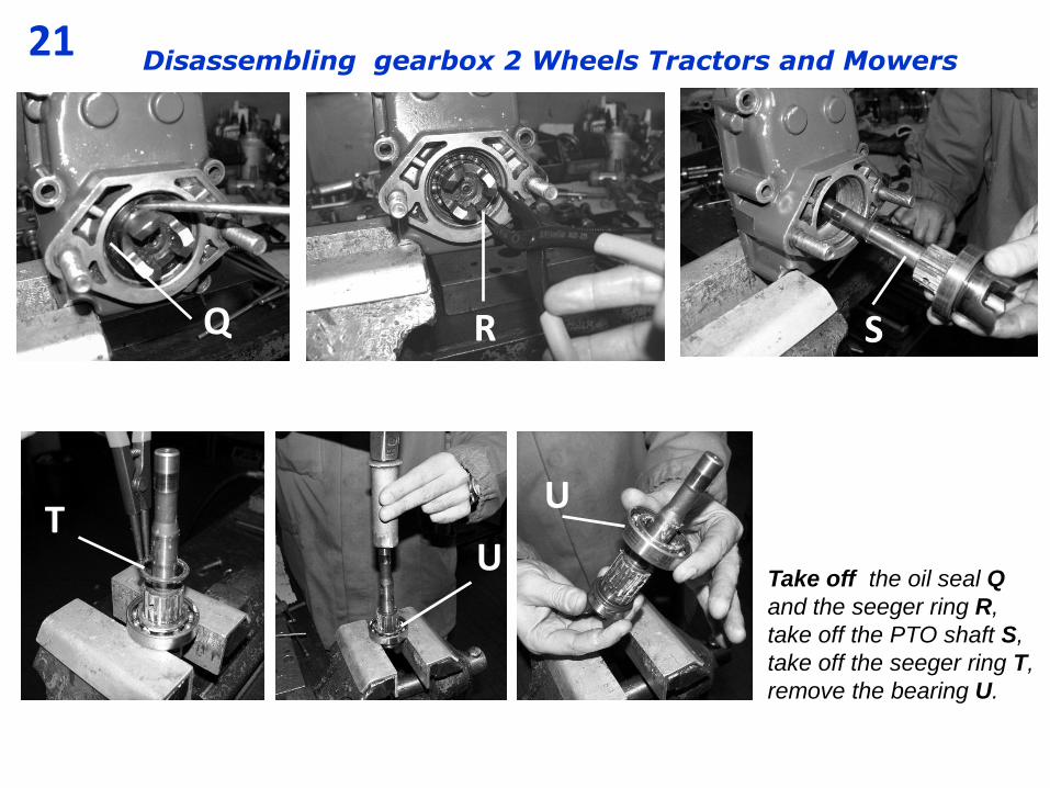
Take off the oil seal Q
and the seeger ring R,
take off the PTO shaft S,
take off the seeger ring T,
remove the bearing U.
U
R Q
T
U

22 Disassembling gearbox 2 Wheels Tractors and Mowers
ATTENTION: from this point we start to
remount the gearbox, in the case needs
to change some wear components or
bearings or external parts to the gearbox
ect. is necessary refer exclusively to the
specific EXPLODED TABLES and to the
SERIAL NUMBER for every model of
machine. The exploded tables are
available on BCS site, the s/n.
is positioned on the gearbox, punched
in the space 1 or 2 in figure A. For the
sealant see table 26. a
f
e d
c b
a – family b – model c – serial number d – table number e – revision f - date A
23 Disassembling gearbox 2 Wheels Tractors and Mowers
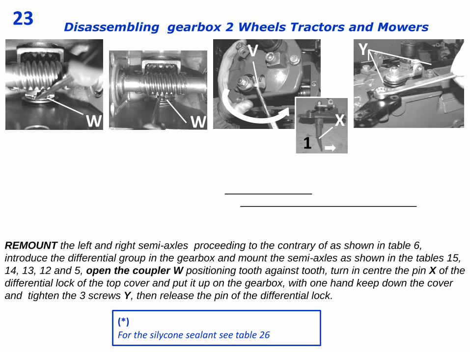
REMOUNT the left and right semi-axles proceeding to the contrary of as shown in table 6,
introduce the differential group in the gearbox and mount the semi-axles as shown in the tables 15,
14, 13, 12 and 5, open the coupler W positioning tooth against tooth, turn in centre the pin X of the
differential lock of the top cover and put it up on the gearbox, with one hand keep down the cover
and tighten the 3 screws Y, then release the pin of the differential lock.
W W
Y V
1
X
(*)
For the silycone sealant see table 26
24 Disassembling gearbox 2 Wheels Tractors and Mowers
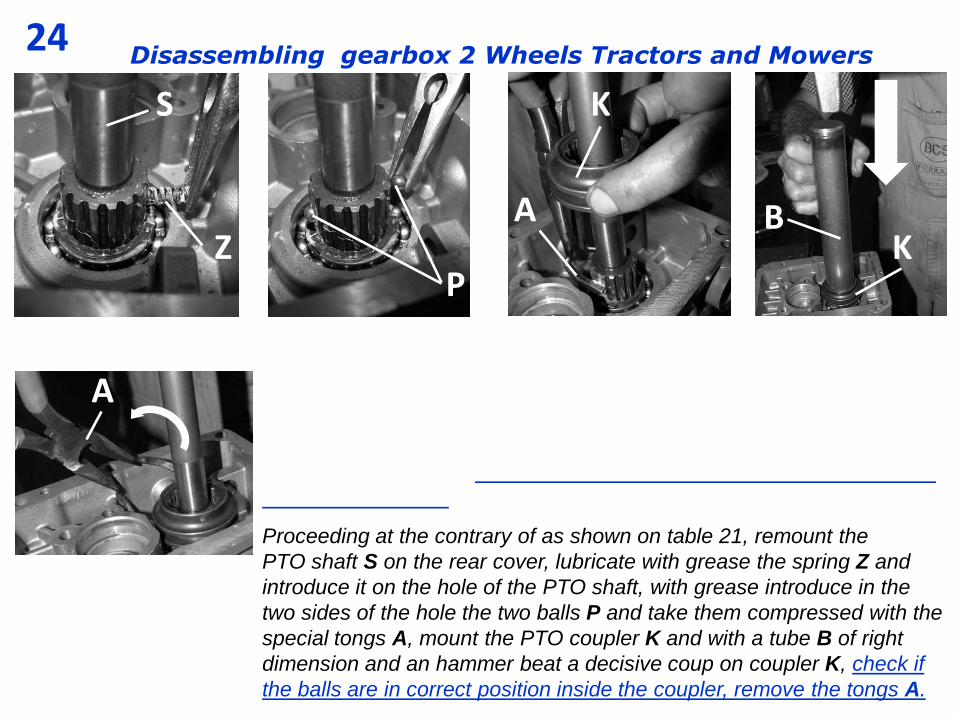
Proceeding at the contrary of as shown on table 21, remount the
PTO shaft S on the rear cover, lubricate with grease the spring Z and
introduce it on the hole of the PTO shaft, with grease introduce in the
two sides of the hole the two balls P and take them compressed with the
special tongs A, mount the PTO coupler K and with a tube B of right
dimension and an hammer beat a decisive coup on coupler K, check if
the balls are in correct position inside the coupler, remove the tongs A.
A
K S
Z P
B K
A
25 Disassembling gearbox 2 Wheels Tractors and Mowers
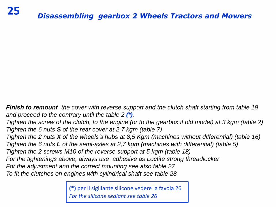
Finish to remount the cover with reverse support and the clutch shaft starting from table 19
and proceed to the contrary until the table 2 (*).
Tighten the screw of the clutch, to the engine (or to the gearbox if old model) at 3 kgm (table 2)
Tighten the 6 nuts S of the rear cover at 2,7 kgm (table 7)
Tighten the 2 nuts X of the wheels’s hubs at 8,5 Kgm (machines without differential) (table 16)
Tighten the 6 nuts L of the semi-axles at 2,7 kgm (machines with differential) (table 5)
Tighten the 2 screws M10 of the reverse support at 5 kgm (table 18)
For the tightenings above, always use adhesive as Loctite strong threadlocker
For the adjustment and the correct mounting see also table 27
To fit the clutches on engines with cylindrical shaft see table 28
(*) per il sigillante silicone vedere la favola 26
For the silicone sealant see table 26
26 Disassembling gearbox 2 Wheels Tractors and Mowers
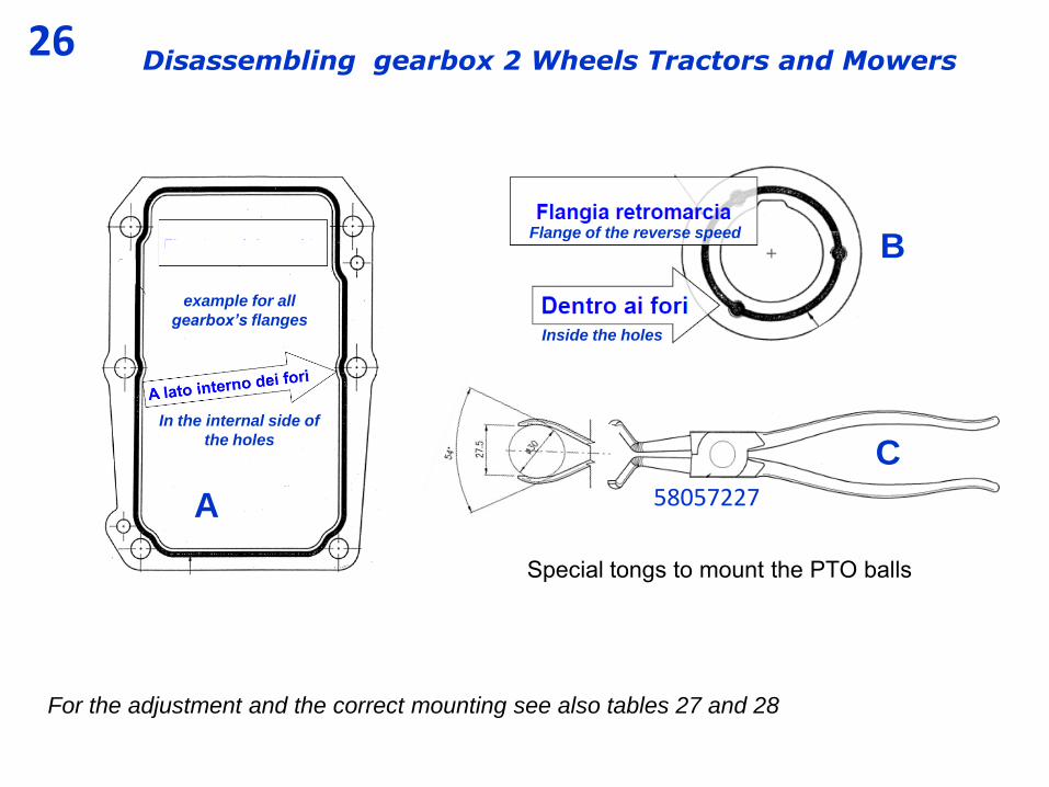
For the adjustment and the correct mounting see also tables 27 and 28
B Flange of the reverse speed
Inside the holes
example for all
gearbox’s flanges
In the internal side of
the holes
A
C
58057227
Special tongs to mount the PTO balls
27 Smontaggio cambio Motocoltivatori e Motofalciatrici Disassembling gearbox 2 Wheels Tractors and Mowers
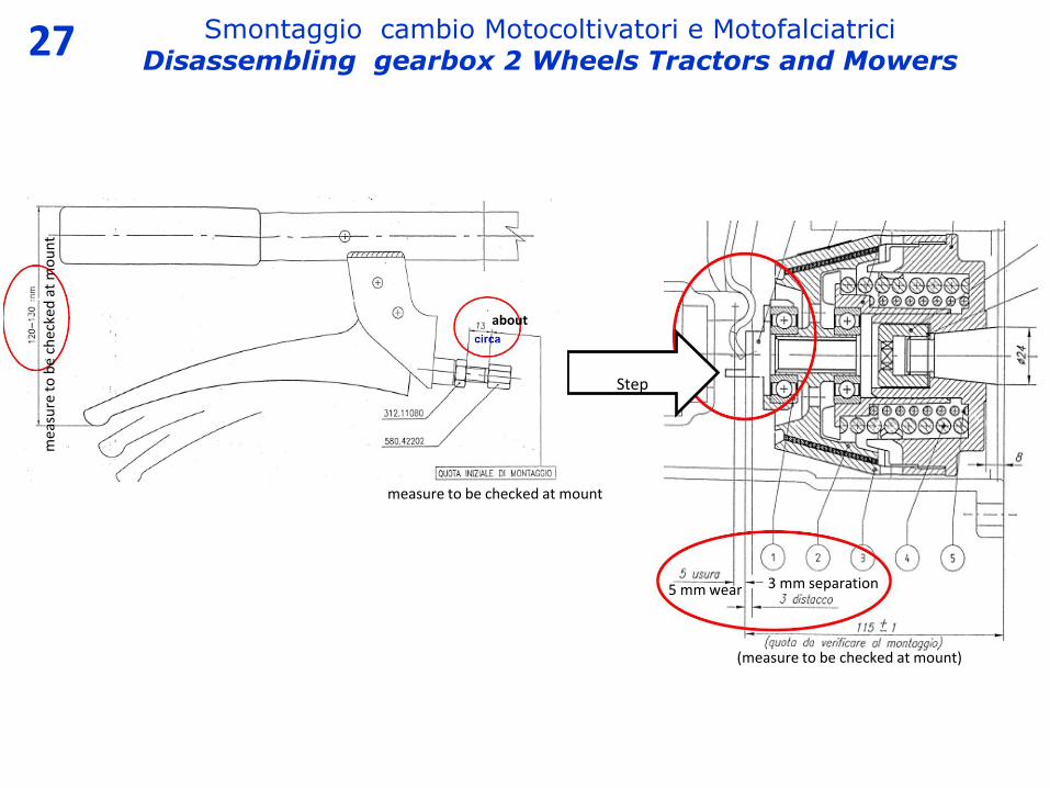
5 mm wear
(measure to be checked at mount)
3 mm separation
Step
measure to be checked at mount
mea
sure
to
be
chec
ked
at
mo
un
t
about
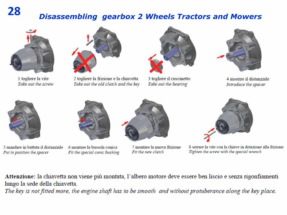
28 Disassembling gearbox 2 Wheels Tractors and Mowers