disc harrow nual - woods equipment company · disc harrow nual man0562 (rev. 4/29/2015) dhm5 dhm6...
TRANSCRIPT

OP
ER
AT
OR
'S M
AN
UA
L
DISC HARROWM
AN
0562
(Rev
. 4/2
9/20
15)
DHM5DHM6DHM7

2 Introduction Gen’l (Rev. 12/5/2011)
TO THE DEALER:
Assembly and proper installation of this product is the responsibility of the Woods® dealer. Read manual instructionsand safety rules. Make sure all items on the Dealer’s Pre-Delivery and Delivery Check Lists in the Operator’s Manualare completed before releasing equipment to the owner.
The dealer must complete the online Product Registration form at the Woods Dealer Website which certifies thatall Dealer Check List items have been completed. Dealers can register all Woods product atdealer.WoodsEquipment.com under Product Registration.
Failure to register the product does not diminish customer’s warranty rights.
TO THE OWNER:
Read this manual before operating your Woods equipment. The information presented will prepare you to do a better andsafer job. Keep this manual handy for ready reference. Require all operators to read this manual carefully and becomeacquainted with all adjustment and operating procedures before attempting to operate. Replacement manuals can beobtained from your dealer. To locate your nearest dealer, check the Dealer Locator at www.WoodsEquipment.com, or inthe United States and Canada call 1-800-319-6637.
The equipment you have purchased has been carefully engineered and manufactured to provide dependable andsatisfactory use. Like all mechanical products, it will require cleaning and upkeep. Lubricate the unit as specified.Observe all safety information in this manual and safety decals on the equipment.
For service, your authorized Woods dealer has trained mechanics, genuine Woods service parts, and the necessarytools and equipment to handle all your needs.
Use only genuine Woods service parts. Substitute parts will void the warranty and may not meet standards required forsafe and satisfactory operation. Record the model number and serial number of your equipment in the spacesprovided:
Model: _______________________________ Date of Purchase: _____________________
Serial Number: (see Safety Decal section for location) ____________________________________
Provide this information to your dealer to obtain correct repair parts.
Throughout this manual, the term NOTICE is used to indicate that failure to observe can cause damage to equipment.The terms CAUTION, WARNING, and DANGER are used in conjunction with the Safety-Alert Symbol (a triangle withan exclamation mark) to indicate the degree of hazard for items of personal safety.
Introduction 3MAN0562 (12/1/2006)
TABLE OF CONTENTS
INTRODUCTION . . . . . . . . . . . . . . . . . . . . . . . . . . . . . . . . . . . . . . . . . . . . . . 2
SPECIFICATIONS. . . . . . . . . . . . . . . . . . . . . . . . . . . . . . . . . . . . . . . . . . . . . 4
GENERAL INFORMATION . . . . . . . . . . . . . . . . . . . . . . . . . . . . . . . . . . . . . . 4
SAFETY RULES . . . . . . . . . . . . . . . . . . . . . . . . . . . . . . . . . . . . . . . . . . . . . . 5
SAFETY DECALS . . . . . . . . . . . . . . . . . . . . . . . . . . . . . . . . . . . . . . . . . . . . . 7
OPERATION . . . . . . . . . . . . . . . . . . . . . . . . . . . . . . . . . . . . . . . . . . . . . . . . . 8
SERVICE. . . . . . . . . . . . . . . . . . . . . . . . . . . . . . . . . . . . . . . . . . . . . . . . . . . 10
ASSEMBLY . . . . . . . . . . . . . . . . . . . . . . . . . . . . . . . . . . . . . . . . . . . . . . . . . 12
DEALER CHECK LISTS . . . . . . . . . . . . . . . . . . . . . . . . . . . . . . . . . . . . . . . 13
PARTS LIST . . . . . . . . . . . . . . . . . . . . . . . . . . . . . . . . . . . . . . . . . . . . . . . . 14
BOLT TORQUE CHART . . . . . . . . . . . . . . . . . . . . . . . . . . . . . . . . . . . . . . . 18
BOLT SIZE CHART & ABBREVIATIONS . . . . . . . . . . . . . . . . . . . . . . . . . . 19
REPLACEMENT PARTS WARRANTY . . . . . . . . . . . . . . . . . . . . . . . . . . . . 20
PRODUCT WARRANTY . . . . . . . . . . . . . . . . . . . . . . . INSIDE BACK COVER
(Rev. 2/15/2015)
4 Introduction MAN0562 (12/1/2006)
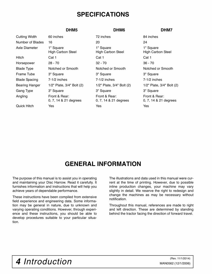
SPECIFICATIONS
GENERAL INFORMATION
The purpose of this manual is to assist you in operatingand maintaining your Disc Harrow. Read it carefully. Itfurnishes information and instructions that will help youachieve years of dependable performance.
These instructions have been compiled from extensivefield experience and engineering data. Some informa-tion may be general in nature, due to unknown andvarying operating conditions. However, through experi-ence and these instructions, you should be able todevelop procedures suitable to your particular situa-tion.
The illustrations and data used in this manual were cur-rent at the time of printing. However, due to possibleinline production changes, your machine may varyslightly in detail. We reserve the right to redesign andchange the machines as may be necessary withoutnotification.
Throughout this manual, references are made to rightand left direction. These are determined by standingbehind the tractor facing the direction of forward travel.
DHM5 DHM6 DHM7
Cutting Width 60 inches 72 inches 84 inches
Number of Blades 16 20 24
Axle Diameter 1" SquareHigh Carbon Steel
1" SquareHigh Carbon Steel
1" SquareHigh Carbon Steel
Hitch Cat 1 Cat 1 Cat 1
Horsepower 28 - 70 32 - 70 36 - 70
Blade Type Notched or Smooth Notched or Smooth Notched or Smooth
Frame Tube 3" Square 3" Square 3" Square
Blade Spacing 7-1/2 inches 7-1/2 inches 7-1/2 inches
Bearing Hanger 1/2" Plate, 3/4" Bolt (2) 1/2" Plate, 3/4" Bolt (2) 1/2" Plate, 3/4" Bolt (2)
Gang Type 3" Square 3" Square 3" Square
Angling Front & Rear:0, 7, 14 & 21 degrees
Front & Rear:0, 7, 14 & 21 degrees
Front & Rear:0, 7, 14 & 21 degrees
Quick Hitch Yes Yes Yes
(Rev. 11/1/2014)

Safety 5Disc Harrow (9/1/2006)
TRAINING
Safety instructions are important! Read allattachment and power unit manuals; follow allsafety rules and safety decal information. (Replace-ment manuals and safety decals are available fromyour dealer. To locate your nearest dealer, checkthe Dealer Locator at www.WoodsEquipment.com,or in the United States and Canada call 1-800-319-6637.) Failure to follow instructions or safety rulescan result in serious injury or death.
If you do not understand any part of this manualand need assistance, see your dealer.
Operators must be instructed in and be capableof the safe operation of the equipment, its attach-ments, and all controls. Do not allow anyone tooperate this equipment without proper instructions.
Never allow children or untrained persons tooperate equipment.
PREPARATION Always wear relatively tight and belted clothingto avoid getting caught in moving parts. Wearsturdy, rough-soled work shoes and protectiveequipment for eyes, hair, hands, hearing, and head;and respirator or filter mask where appropriate.
Make sure attachment is properly secured,adjusted, and in good operating condition.
Power unit must be equipped with ROPS orROPS cab and seat belt. Keep seat belt securelyfastened. Falling off power unit can result in deathfrom being run over or crushed. Keep foldableROPS system in “locked up” position at all times.
A minimum 20% of tractor and equipmentweight must be on the tractor front wheels whenattachments are in transport position. Without thisweight, front tractor wheels could raise up result-ing in loss of steering. The weight may be attainedwith front wheel weights, ballast in tires or fronttractor weights. Weigh the tractor and equipment.Do not estimate.
Consult local utilities before working. Knowlocation of all underground cables, pipelines, over-head wires, and other hazards in working area andavoid contact.
TRANSPORTATION Always comply with all state and local lightingand marking requirements.
Never allow riders on power unit or attachment.
Do not operate or transport on steep slopes.
Use extreme care and reduce ground speed onslopes and rough terrain.
Do not operate or transport equipment whileunder the influence of alcohol or drugs.
OPERATION Always comply with all state and local lightingand marking requirements.
Operate only in daylight or good artificial light.
Keep bystanders away from equipment.
Keep hands, feet, hair, and clothing away fromequipment while engine is running. Stay clear of allmoving parts.
Never allow riders on power unit or attachment.
Power unit must be equipped with ROPS orROPS cab and seat belt. Keep seat belt securelyfastened. Falling off power unit can result in deathfrom being run over or crushed. Keep foldableROPS system in “locked up” position at all times.
Always sit in power unit seat when operatingcontrols or starting engine. Securely fasten seatbelt, place transmission in neutral, engage brake,and ensure all other controls are disengagedbefore starting power unit engine.
Look down and to the rear and make sure areais clear before operating in reverse.
Use extreme care when working close to fences,ditches, other obstructions, or on hillsides.
(Safety Rules continued on next page)
Safety is a primary concern in the design andmanufacture of our products. Unfortunately, ourefforts to provide safe equipment can be wipedout by an operator’s single careless act.
In addition to the design and configuration ofequipment, hazard control and accident preven-tion are dependent upon the awareness, con-cern, judgement, and proper training ofpersonnel involved in the operation, transport,maintenance, and storage of equipment.
It has been said, “The best safety device is aninformed, careful operator.” We ask you to bethat kind of operator.
SAFETY RULESATTENTION! BECOME ALERT! YOUR SAFETY IS INVOLVED!

6 Safety Disc Harrow (9/1/2006)
(Safety Rules continued from previous page)
Do not operate or transport on steep slopes.
Do not stop, start, or change directions sud-denly on slopes.
Use extreme care and reduce ground speed onslopes and rough terrain.
Stop power unit and equipment immediatelyupon striking an obstruction. Turn off engine,remove key, inspect, and repair any damage beforeresuming operation.
Watch for hidden hazards on the terrain duringoperation.
MAINTENANCE Before performing any service or maintenance,lower attachment to ground, turn off engine, setparking brake, and remove key.
Always wear relatively tight and belted clothingto avoid getting caught in moving parts. Wearsturdy, rough-soled work shoes and protectiveequipment for eyes, hair, hands, hearing, and head;and respirator or filter mask where appropriate.
Never go underneath equipment (lowered to theground or raised) unless it is properly blocked andsecured. Never place any part of the body under-neath equipment or between moveable parts even
when the engine has been turned off. Hydraulicsystem leak down, hydraulic system failures,mechanical failures, or movement of control leverscan cause equipment to drop or rotate unexpect-edly and cause severe injury or death.
Make sure attachment is properly secured,adjusted, and in good operating condition.
Never perform service or maintenance withengine running.
Keep all persons away from operator controlarea while performing adjustments, service, ormaintenance.
Tighten all bolts, nuts, and screws to torquechart specifications. Check that all cotter pins areinstalled securely to ensure equipment is in a safecondition before putting unit into service.
STORAGE
To help prevent injury caused by a falling imple-ment, always detach on a hard level surface.
Block equipment securely for storage.
Keep children and bystanders away from stor-age area.
Follow manual instructions for storage.
SAFETY RULESATTENTION! BECOME ALERT! YOUR SAFETY IS INVOLVED!
Safety 7MAN0562 (12/1/2006)
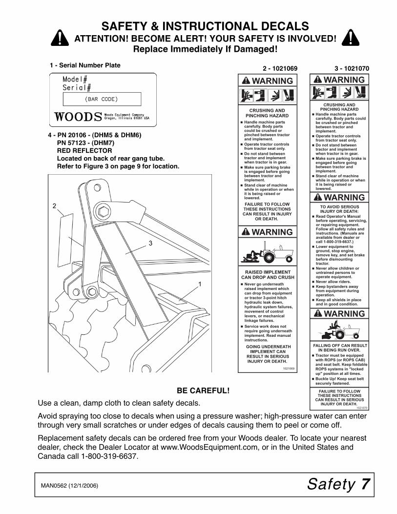
1 - Serial Number Plate 2 - 1021069
BE CAREFUL!
Use a clean, damp cloth to clean safety decals.
Avoid spraying too close to decals when using a pressure washer; high-pressure water can enter through very small scratches or under edges of decals causing them to peel or come off.
Replacement safety decals can be ordered free from your Woods dealer. To locate your nearest dealer, check the Dealer Locator at www.WoodsEquipment.com, or in the United States and Canada call 1-800-319-6637.
3 - 1021070
4 - PN 20106 - (DHM5 & DHM6) PN 57123 - (DHM7) RED REFLECTOR Located on back of rear gang tube. Refer to Figure 3 on page 9 for location.
SAFETY & INSTRUCTIONAL DECALSATTENTION! BECOME ALERT! YOUR SAFETY IS INVOLVED!
Replace Immediately If Damaged!
8 Operation MAN0562 (12/1/2006)
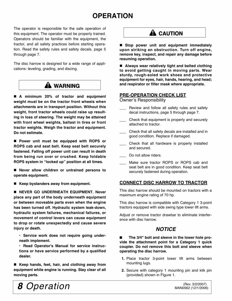
OPERATION
The operator is responsible for the safe operation ofthis equipment. The operator must be properly trained.Operators should be familiar with the equipment, thetractor, and all safety practices before starting opera-tion. Read the safety rules and safety decals, page 5through page 7.
The disc harrow is designed for a wide range of appli-cations: leveling, grading, and discing.
A minimum 20% of tractor and equipmentweight must be on the tractor front wheels whenattachments are in transport position. Without thisweight, front tractor wheels could raise up result-ing in loss of steering. The weight may be attainedwith front wheel weights, ballast in tires or fronttractor weights. Weigh the tractor and equipment.Do not estimate.
Power unit must be equipped with ROPS orROPS cab and seat belt. Keep seat belt securelyfastened. Falling off power unit can result in deathfrom being run over or crushed. Keep foldableROPS system in “locked up” position at all times.
Never allow children or untrained persons tooperate equipment.
Keep bystanders away from equipment.
NEVER GO UNDERNEATH EQUIPMENT. Neverplace any part of the body underneath equipmentor between moveable parts even when the enginehas been turned off. Hydraulic system leak-down,hydraulic system failures, mechanical failures, ormovement of control levers can cause equipmentto drop or rotate unexpectedly and cause severeinjury or death.
• Service work does not require going under-neath implement.• Read Operator's Manual for service instruc-tions or have service performed by a qualifieddealer.
Keep hands, feet, hair, and clothing away fromequipment while engine is running. Stay clear of allmoving parts.
Stop power unit and equipment immediatelyupon striking an obstruction. Turn off engine,remove key, inspect, and repair any damage beforeresuming operation.
Always wear relatively tight and belted clothingto avoid getting caught in moving parts. Wearsturdy, rough-soled work shoes and protectiveequipment for eyes, hair, hands, hearing, and head;and respirator or filter mask where appropriate.
PRE-OPERATION CHECK LISTOwner’s Responsibility
___ Review and follow all safety rules and safetydecal instructions, page 5 through page 7.
___ Check that equipment is properly and securelyattached to tractor.
___ Check that all safety decals are installed and ingood condition. Replace if damaged.
___ Check that all hardware is properly installedand secured.
___ Do not allow riders.
___ Make sure tractor ROPS or ROPS cab andseat belt are in good condition. Keep seat beltsecurely fastened during operation.
CONNECT DISC HARROW TO TRACTOR
This disc harrow should be mounted on tractors with amaximum engine rating of 70 hp.
This disc harrow is compatible with Category 1 3-pointtractors equipped with side swing type lower lift arms.
Adjust or remove tractor drawbar to eliminate interfer-ence with disc harrow.
NOTICE■ The 3/4" bolt and sleeve in the lower hole pro-vide the attachment point for a Category 1 quickcoupler. Do not remove this bolt and sleeve whenoperating the disc harrow.
1. Place tractor 3-point lower lift arms betweenmounting lugs.
2. Secure with category 1 mounting pin and klik pin(provided) shown in Figure 1.
�������
CAUTION
(Rev. 3/2/2007)

Operation 9MAN0562 (12/1/2006)
Figure 1. Category 1 Mounting Pins
3. Attach the tractor's top link to the top of the discharrow’s A-frame bars.
4. Secure with the heavy-duty top link pin andretaining pin supplied with tractor top link.
NOTE: Check torque on each gang axle nut afterthe first five hours of use. Torque to 250 lbs-ft.
Quick Hitch
The disc harrow will attach to a Category 1 quick hitch.
Figure 2. Quick Hitch Bushing Location
1. Use Bushing Kit 1022043 when using a quickcoupler. See “Frame Assembly” on page 14 for listof parts.
2. Remove hitch pins from disc harrow. Placebushings (A) over pins and secure into position.
3. Remove bolt (8), washers (12), nut (10), and toplink bushing (5) from the top of the hitch.
4. Replace top link bushing (5) with bushing (B) fromthe Quick Hitch Kit. Secure using hardwarepreviously removed.
5. Align quick hitch with mounting pins and sleeve inlower hole on disc harrow A-frame bars.
Adjusting Top Link
The disc harrow is leveled by adjusting the length ofthe tractor's top link.
Experience will allow the operator to determine thebest setting for each application.
Angling Blades
1. Using the 3-point lift; raise disc harrow off theground.
2. Remove hitch pin (6) and safety pin.
3. Grasp handle and move carriage to the desiredposition (Figure 3).
4. Insert hitch pin (6) in new hole location and securewith safety pin.
NOTE: The greater the disc angle; the greater thematerial turn over.
Figure 3. Angle Discs
STORAGE
To help prevent injury caused by a falling imple-ment, always detach on a hard level surface.
Block equipment securely for storage.
Do not climb or lean on stored equipment.
Top LinkConnection
Pins
B 8 10 12
A
A. Sleeve, .94 x 1.44 x 2.75B. Sleeve, .81 x 1.25 x 2.405. Top link bushing8. 3/4 NC x 6 HHCS GR5
10. 3/4 NC Lock nut12. 3/4 Flat washer
Handle
DP1
�������
(Rev. 3/2/2007)

10 Service MAN0562 (12/1/2006)
SERVICE
The information in this section is written for operatorswho possess basic mechanical skills. If you need help,your dealer has trained service technicians available.For your protection, read and follow the safety informa-tion in this manual.
NEVER GO UNDERNEATH EQUIPMENT. Neverplace any part of the body underneath equipmentor between moveable parts even when the enginehas been turned off. Hydraulic system leak-down,hydraulic system failures, mechanical failures, ormovement of control levers can cause equipmentto drop or rotate unexpectedly and cause severeinjury or death.
• Service work does not require going under-neath.• Read Operator's Manual for service instruc-tions or have service performed by a qualifieddealer.
Keep all persons away from operator controlarea while performing adjustments, service, ormaintenance.
Always wear relatively tight and belted clothingto avoid getting caught in moving parts. Wearsturdy, rough-soled work shoes and protectiveequipment for eyes, hair, hands, hearing, and head;and respirator or filter mask where appropriate.
DISC REPLACEMENT
Figure 4. Bearing Mount Assembly
1. Remove nuts (12), lock washers (19), cap screws(13), and bearing top plate (14) from both bearingmounts (15) that secure the disc harrow gang tothe frame (Figure 4).
2. Remove jam nut (11), axle nut (10), and small endcap washer (9) on the end of the disc gang shownin Figure 5.
Figure 5. Remove Axle Hardware
3. Slide discs, spacers and bearing mounts off axleas needed to replace desired disc(s) andbearing(s).
NOTE: Maintain proper order of discs, spacers,and bearing mounts for reassembly. See Figure 6or Parts page 16.
Figure 6. Parts Assembly, DH7 Shown
�������
CAUTION
13
1912
1415
12. 3/4 NC Lock nut13. 3/4 NC x 5 HHCS GR514. Bearing top plate15. Bearing mount19. 3/4 Lock washer
11
9
10
9. End cap washer, small10. 1” Lock washer11. 1 “ NC Hex nut, axle
DP5A
(Rev. 3/2/2007)
Service 11MAN0562 (12/1/2006)
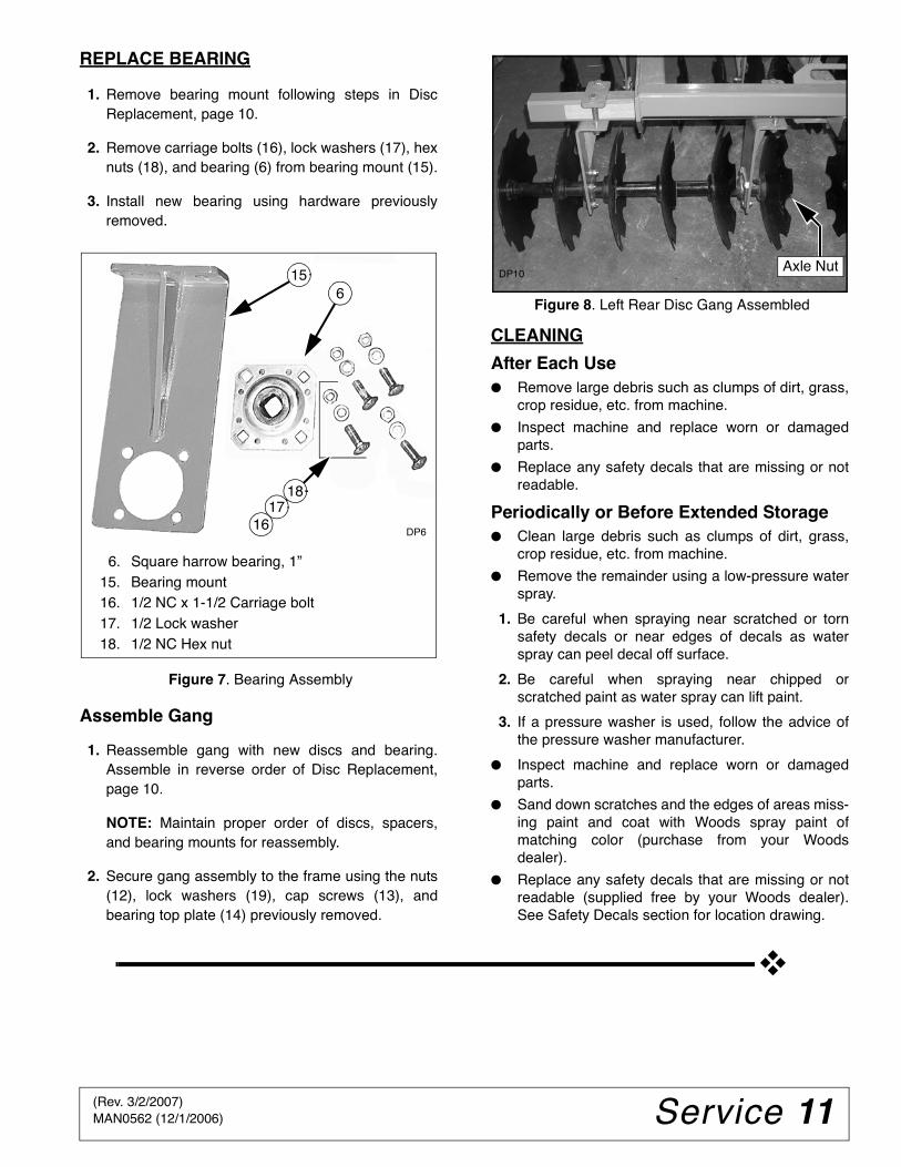
REPLACE BEARING
1. Remove bearing mount following steps in DiscReplacement, page 10.
2. Remove carriage bolts (16), lock washers (17), hexnuts (18), and bearing (6) from bearing mount (15).
3. Install new bearing using hardware previouslyremoved.
Figure 7. Bearing Assembly
Assemble Gang
1. Reassemble gang with new discs and bearing.Assemble in reverse order of Disc Replacement,page 10.
NOTE: Maintain proper order of discs, spacers,and bearing mounts for reassembly.
2. Secure gang assembly to the frame using the nuts(12), lock washers (19), cap screws (13), andbearing top plate (14) previously removed.
Figure 8. Left Rear Disc Gang Assembled
CLEANING
After Each Use● Remove large debris such as clumps of dirt, grass,
crop residue, etc. from machine.
● Inspect machine and replace worn or damagedparts.
● Replace any safety decals that are missing or notreadable.
Periodically or Before Extended Storage● Clean large debris such as clumps of dirt, grass,
crop residue, etc. from machine.
● Remove the remainder using a low-pressure waterspray.
1. Be careful when spraying near scratched or tornsafety decals or near edges of decals as waterspray can peel decal off surface.
2. Be careful when spraying near chipped orscratched paint as water spray can lift paint.
3. If a pressure washer is used, follow the advice ofthe pressure washer manufacturer.
● Inspect machine and replace worn or damagedparts.
● Sand down scratches and the edges of areas miss-ing paint and coat with Woods spray paint ofmatching color (purchase from your Woodsdealer).
● Replace any safety decals that are missing or notreadable (supplied free by your Woods dealer).See Safety Decals section for location drawing.
156
1617
18
DP6
6. Square harrow bearing, 1”15. Bearing mount16. 1/2 NC x 1-1/2 Carriage bolt17. 1/2 Lock washer18. 1/2 NC Hex nut
DP10Axle Nut
(Rev. 3/2/2007)

12 Assembly MAN0562 (9/1/2006)
ASSEMBLY INSTRUCTIONS
DEALER SET-UP INSTRUCTIONSAssembly of this Disc Harrow is the responsibility of theWOODS dealer. The Disc Harrow is shipped com-pletely assembled but may require gang assemblyadjustment.
Gang assemblies should be adjusted to the dimen-sions shown in Figure 7 and Table 1. Torque values forhardware are located on page 18.
Disc Harrow should be delivered to the owner com-pletely assembled, lubricated and adjusted for normalconditions.
Complete the Dealer Checklist on page 13 when set-upis complete and Disc Harrow is delivered to the owner.
Table 1: Gang Offset Dimensions
NEVER GO UNDERNEATH EQUIPMENT. Neverplace any part of the body underneath equipmentor between moveable parts even when the enginehas been turned off. Hydraulic system leak-down,hydraulic system failures, mechanical failures, ormovement of control levers can cause equipmentto drop or rotate unexpectedly and cause severeinjury or death.
• Service work does not require going under-neath implement.• Read Operator's Manual for service instruc-tions or have service performed by a qualifieddealer.
Keep all persons away from operator controlarea while performing adjustments, service, ormaintenance.
Always wear relatively tight and belted clothingto avoid entanglement in moving parts. Wearsturdy, rough-soled work shoes and protectiveequipment for eyes, hair, hands, hearing, and head;and respirator or filter mask where appropriate.
Figure 7. Gang Assembly Adjustment
ModelOffset (Inches)
“A” Front “B” RearDHM5 3.5 3.0DHM6 3.0 2.5DHM7 2.5 2.0
�������
CAUTION
(Rev. 2/15/2015)

Dealer Check Lists 13MAN0562 (9/1/2006)
DEALER CHECK LISTS
PRE-DELIVERY CHECK LIST(DEALER’S RESPONSIBILITY)
Inspect the equipment thoroughly after assembly toensure it is set up properly before delivering it to thecustomer.
The following check lists are a reminder of points toinspect. Check off each item as it is found satisfactoryor after proper adjustment is made.
___ Check that all safety decals are installed and ingood condition. Replace if damaged.
___ Check gang assembly offset and adjust asnecessary.
___ Properly attach implement to tractor and makeall necessary adjustments.
___ Check all bolts to be sure they are properlytorqued.
___ Check that all cotter pins and safety pins areproperly installed. Replace if damaged.
DELIVERY CHECK LIST(DEALER’S RESPONSIBILITY)
___ Show customer how to make adjustments.
___ Point out the safety decals. Explain their mean-ing and the need to keep them in place and ingood condition. Emphasize the increasedsafety hazards when instructions are not fol-lowed.
___ Present Operator's Manual and request thatcustomer and all operators read it before oper-ating equipment. Point out the manual safetyrules, explain their meanings and emphasizethe increased safety hazards that exist whensafety rules are not followed.
___ For mounted units, add wheel weights, ballastin front tires, and/or front tractor weight toenhance front end stability. A minimum 20% oftractor and equipment gross weight must be onfront tractor wheels. When adding weight toattain 20% of tractor and equipment weight onfront tractor wheels, you must not exceed theROPS weight certification. Weigh the tractorand equipment. Do not estimate!
___ Make customer aware of optional equipmentavailable so that customer can make properchoices as required.
(Rev. 2/15/2015)

14 Parts MAN0562 (12/1/2006)
FRAME ASSEMBLY
3
1
24
5 8 10 12
712
11
10
1210
9
DH1
6
REF PART QTY DESCRIPTION
1 1022508 1 Frame (DHM5 & DHM6) -or-
1 1022252 1 Frame (DHM7)
2 1022509 4 Gang tube 60" (DHM5)
2 1022510 4 Gang tube 72" (DHM6)
2 1022511 4 Gang tube 84" (DHM7)
3 1022507 4 Cap, 3" x 3" Black plastic
4 1022567 1 Left A-Frame bar(includes decal 1021070) -or-
4 1022568 1 Right A-frame bar(includes decal 1021069)
5 1022046 1 Sleeve, .81 x 1.25 x 2.62
6 1022514 1 A-Frame brace
7 SU105 2 Category 1 drawbar pin w/lynch
8 2377 * 1 3/4 NC x 6 HHCS GR5
REF PART QTY DESCRIPTION
9 2376 * 1 3/4 NC x 5 HHCS GR5
10 2371 * 4 3/4 NC Lock nut
11 30068 * 2 3/4 NC x 2-1/2 HHCS GR5
12 1257 * 8 3/4 Flat washer
13 1022028 1 Complete decal set, DHM
14 1022043 † 1 Quick hitch bushing kit (optional)includes A & B
A -------- 2 Sleeve, .94 x 1.44 x 2.75
B -------- 1 Sleeve, .81 x 1.25 x 2.40
15 1025163 † 1 Hitch pin, 3/4 x 4-1/4 (top link)
† Not Shown
HHCS Hex Head Cap Screw
* Standard hardware, obtain locally
(Rev. 4/29/2015)

Parts 15MAN0562 (12/1/2006)
ANGLE ADJUSTMENT ASSEMBLY(ONE SET SHOWN)
5
461
2
DH3
REF PART QTY DESCRIPTION
1 1022505 2 Top adjustment bracket
2 1022506 2 Bottom adjustment bracket
4 378 * 4 5/8 NC x 5 HHCS GR5
REF PART QTY DESCRIPTION
5 6239 * 4 5/8 NC Lock nut
6 SU105 2 Category 1 drawbar pin w/lynch
HHCS Hex Head Cap Screw
* Standard hardware, obtain locally

16 Parts MAN0562 (12/1/2006)
GANG ASSEMBLY(ONE DHM7 SET SHOWN)
3
1
6
77910
5
15
1718
16
8
DH5A
5220
DISCDISC
DISC
12
8
1314
11
REF PART QTY DESCRIPTION
1 1011299 4 Disc Harrow axle 1" x 26" (DHM5)
1 1011277 4 Disc Harrow axle 1" x 34" (DHM6)
1 1011279 4 Disc Harrow axle 1" x 41" (DHM7)
2 1011322 8 End cap/bumper washer, large
3 1011258 AR 18” Plain disc blade (not shown)
3 1011274 AR 18” Notched disc blade
5 1011323 8 Spool spacer, 3-5/8"
6 1022500 8 Square harrow bearing, 1"
7 1011324 8 Spool spacer, 2-3/8"
8 1011349 8 Plain spool, 7-7/16"
9 1022501 4 End cap washer, small
10 3689 * 4 1" Lock washer
REF PART QTY DESCRIPTION
11 3132 * 4 1" NC Hex nut (axle nut)
12 FA446 * 16 3/4 NC Nylok nut
13 2376 * 16 3/4 NC x 5 HHCS GR5
14 1022503 8 Bearing, top plate
15 1022502 2 Bearing mount
16 29893 * 32 1/2 NC x 1-1/2 Carriage bolt
17 855 * 32 1/2 Lock washer
18 1093 * 32 1/2 NC Hex nut
20 1022544 AR Washer, 3.5 x 1.41 x .31
AR As required
HHCS Hex Head Cap Screw
* Standard hardware, obtain locally
(Rev. 3/2/2007)

Parts 17MAN0562 (12/1/2006)
MUD SCRAPER ASSEMBLY (OPTIONAL)(ONE DHM7 KIT SHOWN)
DHM5 DHM6 DHM7REF PART QTY PART QTY PART QTY DESCRIPTION
1036473 1036474 1036475 Mud scraper kit1 1035662 4 1035662 8 1035662 4 U-Bolt, 3/8 NC2 14350* 8 14350* 16 14350* 24 3/8 NC Flanged lock nut3 1037494 4 1037494 4 1037494 4 Scraper, bearing mount, RH4 1037495 4 1037495 4 1037495 4 Scraper, bearing mount, LH5 1037478 2 1037478 2 1037478 2 Scraper, channel, RH6 1037479 2 1037479 2 1037479 2 Scraper, channel, LH7 ------- -- 1037486 2 1037486 4 Scraper, link, RH8 ------- -- 1037487 2 1037487 4 Scraper, link, LH
* Standard Hardware, Obtain Locally
(Rev. 2/15/2015)
18 Appendix Bolt Torque & Size Charts (Rev. 3/28/2007)
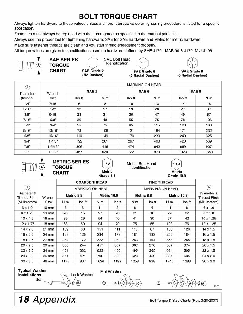
BOLT TORQUE CHARTAlways tighten hardware to these values unless a different torque value or tightening procedure is listed for a specific application.Fasteners must always be replaced with the same grade as specified in the manual parts list.Always use the proper tool for tightening hardware: SAE for SAE hardware and Metric for metric hardware.Make sure fastener threads are clean and you start thread engagement properly. All torque values are given to specifications used on hardware defined by SAE J1701 MAR 99 & J1701M JUL 96.
Diameter (Inches)
WrenchSize
MARKING ON HEAD
SAE 2 SAE 5 SAE 8
lbs-ft N-m lbs-ft N-m lbs-ft N-m
1/4" 7/16" 6 8 10 13 14 18
5/16" 1/2" 12 17 19 26 27 37
3/8" 9/16" 23 31 35 47 49 67
7/16" 5/8" 36 48 55 75 78 106
1/2" 3/4" 55 75 85 115 120 163
9/16" 13/16" 78 106 121 164 171 232
5/8" 15/16" 110 149 170 230 240 325
3/4" 1-1/8" 192 261 297 403 420 569
7/8" 1-5/16" 306 416 474 642 669 907
1" 1-1/2" 467 634 722 979 1020 1383
Diameter & Thread Pitch (Millimeters)
Wrench Size
COARSE THREAD FINE THREAD
Diameter & Thread Pitch (Millimeters)
MARKING ON HEAD MARKING ON HEAD
Metric 8.8 Metric 10.9 Metric 8.8 Metric 10.9
N-m lbs-ft N-m lbs-ft N-m lbs-ft N-m lbs-ft
6 x 1.0 10 mm 8 6 11 8 8 6 11 8 6 x 1.0
8 x 1.25 13 mm 20 15 27 20 21 16 29 22 8 x 1.0
10 x 1.5 16 mm 39 29 54 40 41 30 57 42 10 x 1.25
12 x 1.75 18 mm 68 50 94 70 75 55 103 76 12 x 1.25
14 x 2.0 21 mm 109 80 151 111 118 87 163 120 14 x 1.5
16 x 2.0 24 mm 169 125 234 173 181 133 250 184 16 x 1.5
18 x 2.5 27 mm 234 172 323 239 263 194 363 268 18 x 1.5
20 x 2.5 30 mm 330 244 457 337 367 270 507 374 20 x 1.5
22 x 2.5 34 mm 451 332 623 460 495 365 684 505 22 x 1.5
24 x 3.0 36 mm 571 421 790 583 623 459 861 635 24 x 2.0
30 x 3.0 46 mm 1175 867 1626 1199 1258 928 1740 1283 30 x 2.0
A
SAE SERIES TORQUE CHART
SAE Bolt Head Identification
SAE Grade 2(No Dashes)
SAE Grade 5(3 Radial Dashes)
SAE Grade 8(6 Radial Dashes)
A
METRIC SERIES TORQUE CHART
Metric Bolt Head Identification
8.8
MetricGrade 10.9
10.9
MetricGrade 8.8
A
A A
Typical Washer Installations Lock Washer
Flat Washer
8/9/00
Bolt

Appendix 19Bolt Torque & Size Charts (Rev. 3/28/2007)
BOLT SIZE CHARTNOTE: Chart shows bolt thread sizes and corresponding head (wrench) sizes for standard SAE and metric bolts.
ABBREVIATIONSAG .............................................................. AgricultureASABE.................... American Society of Agricultural &
Biological Engineers (formerly ASAE)ASAE ....... American Society of Agricultural EngineersATF ............................... Automatic Transmission FluidBSPP .............................British Standard Pipe ParallelBSPTM ................British Standard Pipe Tapered MaleCV.....................................................Constant VelocityCCW .............................................. Counter-ClockwiseCW............................................................... ClockwiseF ...................................................................... FemaleFT .............................................................. Full ThreadGA .................................................................... GaugeGR (5, etc.) ........................................... Grade (5, etc.)HHCS ........................................Hex Head Cap ScrewHT........................................................... Heat-TreatedJIC .................Joint Industry Council 37° Degree FlareLH .................................................................Left HandLT........................................................................... Leftm......................................................................... Metermm................................................................MillimeterM.......................................................................... Male
MPa.........................................................Mega Pascal
N.......................................................................Newton
NC ......................................................National Coarse
NF ...........................................................National Fine
NPSM.....................National Pipe Straight Mechanical
NPT .......................................... National Pipe Tapered
NPT SWF .........National Pipe Tapered Swivel Female
ORBM .......................................... O-Ring Boss - Male
P...........................................................................Pitch
PBY ...................................................... Power-Beyond
psi..........................................Pounds per Square Inch
PTO..................................................... Power Take Off
QD....................................................Quick Disconnect
RH ..............................................................Right Hand
ROPS ........................... Roll-Over Protective Structure
RPM ........................................Revolutions Per Minute
RT ....................................................................... Right
SAE ..........................Society of Automotive Engineers
UNC .....................................................Unified Coarse
UNF...........................................................Unified Fine
UNS......................................................Unified Special
5/16 3/8 1/2 5/8 3/4 7/8SAE Bolt Thread Sizes
MM 25 50 75 100 125 150 175
IN 1 7
Metric Bolt Thread Sizes8MM 18MM14MM12MM10MM 16MM
2 3 4 5 6

F-8494 (Rev. 10/3/2011)
WARRANTY(Replacement Parts For All Models Except Mow’n MachineTM
Zero-Turn Mowers)
Woods Equipment Company (“WOODS”) warrants this product to be free from defect in material andworkmanship for a period of ninety (90) days from the date of delivery of the product to the originalpurchaser with the exception of V-belts, which will be free of defect in material and workmanship for aperiod of 12 months.
Under no circumstances will this Warranty apply in the event that the product, in the good faith opinion ofWOODS, has been subjected to improper operation, improper maintenance, misuse, or an accident. ThisWarranty does not cover normal wear or tear, or normal maintenance items.
This Warranty is extended solely to the original purchaser of the product. Should the original purchaser sellor otherwise transfer this product to a third party, this Warranty does not transfer to the third party purchaserin any way. There are no third party beneficiaries of this Warranty.
WOODS’ obligation under this Warranty is limited to, at WOODS’ option, the repair or replacement, free ofcharge, of the product if WOODS, in its sole discretion, deems it to be defective or in noncompliance withthis Warranty. The product must be returned to WOODS with proof of purchase within thirty (30)days after such defect or noncompliance is discovered or should have been discovered, routed throughthe dealer and distributor from whom the purchase was made, transportation charges prepaid.WOODS shall complete such repair or replacement within a reasonable time after WOODS receives theproduct. THERE ARE NO OTHER REMEDIES UNDER THIS WARRANTY. THE REMEDY OFREPAIR OR REPLACEMENT IS THE SOLE AND EXCLUSIVE REMEDY UNDER THISWARRANTY.
THERE ARE NO WARRANTIES WHICH EXTEND BEYOND THE DESCRIPTION ON THE FACE OFTHIS WARRANTY. WOODS MAKES NO OTHER WARRANTY, EXPRESS OR IMPLIED, ANDWOODS SPECIFICALLY DISCLAIMS ANY IMPLIED WARRANTY OF MERCHANTABILITY AND/OR ANY IMPLIED WARRANTY OF FITNESS FOR A PARTICULAR PURPOSE.
WOODS shall not be liable for any incidental or consequential losses, damages or expenses, arisingdirectly or indirectly from the product, whether such claim is based upon breach of contract, breachof warranty, negligence, strict liability in tort or any other legal theory. Without limiting the generalityof the foregoing, Woods specifically disclaims any damages relating to (i) lost profits, business, revenues orgoodwill; (ii) loss of crops; (iii) loss because of delay in harvesting; (iv) any expense or loss incurred forlabor, supplies, substitute machinery or rental; or (v) any other type of damage to property or economic loss.
This Warranty is subject to any existing conditions of supply which may directly affect WOODS’ ability toobtain materials or manufacture replacement parts.
No agent, representative, dealer, distributor, service person, salesperson, or employee of any company,including without limitation, WOODS, its authorized dealers, distributors, and service centers, is authorizedto alter, modify, or enlarge this Warranty.
Answers to any questions regarding warranty service and locations may be obtained by contacting:

F-3079 (Rev. 3/2/2012)
Woods Equipment Company2606 South Illinois Route 2 Post Office Box 1000Oregon, Illinois 61061 USA
800-319-6637 tel800-399-6637 faxwww.WoodsEquipment.com
WARRANTYAll Models Except Mow’n MachineTM Zero-Turn Mowers
Please Enter Information Below and Save for Future Reference.
Date Purchased: ____________________________ From (Dealer): __________________________________________
Model Number: ____________________________ Serial Number: __________________________________________
Woods Equipment Company (“WOODS”) warrants this product to be free from defect in material and workmanship. Except as otherwise set forthbelow, the duration of this Warranty shall be for TWELVE (12) MONTHS COMMENCING ON THE DATE OF DELIVERY OF THEPRODUCT TO THE ORIGINAL PURCHASER.
All current model loaders and backhoes are warranted for two (2) years from the date of delivery to the original purchaser.
The warranty periods for specific parts or conditions are listed below:
Under no circumstances will this Warranty apply in the event that the product, in the good faith opinion of WOODS, has been subjected toimproper operation, improper maintenance, misuse, or an accident. This Warranty does not apply in the event that the product has been materiallymodified or repaired by someone other than WOODS, a WOODS authorized dealer or distributor, and/or a WOODS authorized service center.This Warranty does not cover normal wear or tear, or normal maintenance items. This Warranty also does not cover repairs made with parts otherthan those obtainable through WOODS.
This Warranty is extended solely to the original purchaser of the product. Should the original purchaser sell or otherwise transfer this product to athird party, this Warranty does not transfer to the third party purchaser in any way. There are no third party beneficiaries of this Warranty.
WOODS makes no warranty, express or implied, with respect to engines, batteries, tires or other parts or accessories not manufactured byWOODS. Warranties for these items, if any, are provided separately by their respective manufacturers.
WOODS’ obligation under this Warranty is limited to, at WOODS’ option, the repair or replacement, free of charge, of the product if WOODS, inits sole discretion, deems it to be defective or in noncompliance with this Warranty. The product must be returned to WOODS with proof ofpurchase within thirty (30) days after such defect or noncompliance is discovered or should have been discovered, routed through thedealer and distributor from whom the purchase was made, transportation charges prepaid. WOODS shall complete such repair orreplacement within a reasonable time after WOODS receives the product. THERE ARE NO OTHER REMEDIES UNDER THIS WARRANTY.THE REMEDY OF REPAIR OR REPLACEMENT IS THE SOLE AND EXCLUSIVE REMEDY UNDER THIS WARRANTY.
THERE ARE NO WARRANTIES WHICH EXTEND BEYOND THE DESCRIPTION ON THE FACE OF THIS WARRANTY. WOODSMAKES NO OTHER WARRANTY, EXPRESS OR IMPLIED, AND WOODS SPECIFICALLY DISCLAIMS ANY IMPLIED WARRANTYOF MERCHANTABILITY AND/OR ANY IMPLIED WARRANTY OF FITNESS FOR A PARTICULAR PURPOSE.
WOODS shall not be liable for any incidental or consequential losses, damages or expenses, arising directly or indirectly from theproduct, whether such claim is based upon breach of contract, breach of warranty, negligence, strict liability in tort or any other legaltheory. Without limiting the generality of the foregoing, Woods specifically disclaims any damages relating to (i) lost profits, business, revenuesor goodwill; (ii) loss of crops; (iii) loss because of delay in harvesting; (iv) any expense or loss incurred for labor, supplies, substitute machinery orrental; or (v) any other type of damage to property or economic loss.
This Warranty is subject to any existing conditions of supply which may directly affect WOODS’ ability to obtain materials or manufacturereplacement parts.
No agent, representative, dealer, distributor, serviceperson, salesperson, or employee of any company, including without limitation, WOODS, itsauthorized dealers, distributors, and service centers, is authorized to alter, modify, or enlarge this Warranty. Answers to any questions regardingwarranty service and locations may be obtained by contacting:
Part or Condition Warranted
Model NumberDuration (from date of delivery to the original
purchaser)
All units invoiced after 4/30/2012
Gearbox components
BW1260, BW1620, BW1800, BW1260X, BW1800X, BW2400
6 years
BW240HD, BW180HD, BW180HB, BW126HB, BW126XHD, BW180XHD
BB48X, BB60X, BB72X, BB84X, BB600X, BB720X, BB840X, BB6000X, BB7200X, BB8400X,DS1260, DSO1260, DS1440, TS1680, BW126-3, BW180-3, BW240, BW126X, BW180X
PHD25, PHD35, PHD65, PHD95, DS96, DS120, RCC42, RD990X, PRD6000, PRD7200, PRD8400,S15CD, S20CD, S22CD, S25CD, S27CD, S30CD BW15LH, TC/R74, TC/R68, TC/R60, TBW144,TBW180, TBW204
RDC54, RD60, RD72, TBW150C, TS/R60, TS/R52, TS/R44, HC48, HC54, HC60, HC72 3 years (1 year if used in rental or commercial applications)
Blade spindles RD990X, PRD6000, PRD7200, PRD8400, TBW144, TBW180, TBW204 3 years
Rust-through BB600, BB720, BB840, BB6000, BB7200, BB8400, BW126-3, BW126HB, BW180-3, BW180HB,BW180HD, BW1260, BW1800, BW240, BW240HD, DS1260, DSO1260, DS1440, TS1680 10 years

PART NO.
MAN0562
© 2006 Woods Equipment Company. All rights reserved. WOODS, the Woods logo, and "Tested. Proven. Unbeatable." are trademarks of WoodsEquipment Company. All other trademarks, trade names, or service marks not owned by Woods Equipment Company that appear in this manualare the property of their respective companies or mark holders. Specifications subject to change without notice.
Woods Equipment Company
2606 South Illinois Route 2Post Office Box 1000Oregon, Illinois 61061
800-319-6637 tel800-399-6637 faxwww.WoodsEquipment.com