discharge characterization of 40 cm-microwave ecr ion
TRANSCRIPT
John E. Foster and Michael J. PattersonGlenn Research Center, Cleveland, Ohio
Melissa BrittonQSS Group, Inc., Cleveland, Ohio
Discharge Characterization of40 cm-Microwave ECR IonSource and Neutralizer
NASA/TM—2003-212590
October 2003
AIAA–2003–5012

The NASA STI Program Office . . . in Profile
Since its founding, NASA has been dedicated tothe advancement of aeronautics and spacescience. The NASA Scientific and TechnicalInformation (STI) Program Office plays a key partin helping NASA maintain this important role.
The NASA STI Program Office is operated byLangley Research Center, the Lead Center forNASA’s scientific and technical information. TheNASA STI Program Office provides access to theNASA STI Database, the largest collection ofaeronautical and space science STI in the world.The Program Office is also NASA’s institutionalmechanism for disseminating the results of itsresearch and development activities. These resultsare published by NASA in the NASA STI ReportSeries, which includes the following report types:
∑ TECHNICAL PUBLICATION. Reports ofcompleted research or a major significantphase of research that present the results ofNASA programs and include extensive dataor theoretical analysis. Includes compilationsof significant scientific and technical data andinformation deemed to be of continuingreference value. NASA’s counterpart of peer-reviewed formal professional papers buthas less stringent limitations on manuscriptlength and extent of graphic presentations.
∑ TECHNICAL MEMORANDUM. Scientificand technical findings that are preliminary orof specialized interest, e.g., quick releasereports, working papers, and bibliographiesthat contain minimal annotation. Does notcontain extensive analysis.
∑ CONTRACTOR REPORT. Scientific andtechnical findings by NASA-sponsoredcontractors and grantees.
∑ CONFERENCE PUBLICATION. Collectedpapers from scientific and technicalconferences, symposia, seminars, or othermeetings sponsored or cosponsored byNASA.
∑ SPECIAL PUBLICATION. Scientific,technical, or historical information fromNASA programs, projects, and missions,often concerned with subjects havingsubstantial public interest.
∑ TECHNICAL TRANSLATION. English-language translations of foreign scientificand technical material pertinent to NASA’smission.
Specialized services that complement the STIProgram Office’s diverse offerings includecreating custom thesauri, building customizeddatabases, organizing and publishing researchresults . . . even providing videos.
For more information about the NASA STIProgram Office, see the following:
∑ Access the NASA STI Program Home Pageat http://www.sti.nasa.gov
∑ E-mail your question via the Internet [email protected]
∑ Fax your question to the NASA AccessHelp Desk at 301–621–0134
∑ Telephone the NASA Access Help Desk at301–621–0390
∑ Write to: NASA Access Help Desk NASA Center for AeroSpace Information 7121 Standard Drive Hanover, MD 21076
John E. Foster and Michael J. PattersonGlenn Research Center, Cleveland, Ohio
Melissa BrittonQSS Group, Inc., Cleveland, Ohio
Discharge Characterization of40 cm-Microwave ECR IonSource and Neutralizer
NASA/TM—2003-212590
October 2003
National Aeronautics andSpace Administration
Glenn Research Center
Prepared for the39th Joint Propulsion Conference and Exhibitcosponsored by the AIAA, ASME, SAE, and ASEEHuntsville, Alabama, July 20–23, 2003
AIAA–2003–5012

Available from
NASA Center for Aerospace Information7121 Standard DriveHanover, MD 21076
National Technical Information Service5285 Port Royal RoadSpringfield, VA 22100
Available electronically at http://gltrs.grc.nasa.gov
NASA/TM�2003-212590 1
Discharge Characterization of 40 cm-Microwave ECR Ion Source and Neutralizer
John E. Foster and Michael J. Patterson National Aeronautics and Space Administration
Glenn Research Center Cleveland, Ohio 44135
Melissa Britton QSS Group, Inc.
Cleveland, Ohio 44135
Discharge characteristics of a 40 cm, 2.45 GHz Electron Cyclotron Resonance (ECR) ion thruster discharge chamber and neutralizer were acquired. Thruster bulk discharge plasma characteristics were assessed using a single Langmuir probe. Total extractable ion current was measured as a function of input microwave power and flow rate. Additionally, radial ion current density profiles at the thruster�s exit plane were characterized using five equally spaced Faraday probes. Distinct low and high density operating modes were observed as discharge input power was varied from 0 to 200 W. In the high mode, extractable ion currents as high as 0.82 A were measured. Neutralizer emission current was characterized as a function of flow rate and microwave power. Neutralizer extraction currents as high as 0.6 A were measured.
Nomenclature e = 1.6 x 10⁻¹⁹ C k = 1.38 x 10⁻²³ J/K
em = 9.11 x 10⁻³¹ kg
iM = Ion mass
eT = Electron temperature (eV) Γ = Ion current density (A/m2)
pω =Plasma frequency (radians/s)
µw = Microwave excitation frequency (radians/s)
cew = Electron cyclotron frequency (radians/s)
Introduction
Propulsion systems capable of providing very high specific impulse (6000-9000 s) are desirable as primary propulsion options for far term missions to the outer planets and beyond. Gridded ion thrusters systems are capable of satisfying such mission requirements. Ion thruster systems used for such an application will be required to operate continuously for perhaps as long as 5-10 years. 1,2 Such long continuous operation times place stringent lifetime requirements on thruster components and subsystems.
In general, thruster lifetime is limited by essentially 4 potential failure modes: 1.) discharge cathode failure, 2.) neutralizer failure, 3.) ion optics failure and 4.) electron backstreaming. Failure modes 1 and 2 are related primarily to hollow cathode failure. Failure mode 3 is related to screen and accelerator grid degradation via erosion as well as grid to grid shorts arising from such erosion phenomena. Electron backstreaming becomes more and more of a problem as accelerator grid apertures widen due to erosion. High levels of backstreaming electrons can destroy the discharge cathode. One potential solution to this problem is the use of a magnetic grid.3 Potential design solutions also exist for increasing the lifetime of the ion optics such as the use of different electrode materials such as titanium4 or carbon5 or by simply increasing the electrode thickness6. Hollow cathode failure can occur after prolonged operation due physical erosion or to the depletion of barium in the insert brought on by barium diffusion and subsequent evaporation or the formation tungstates that tie up the barium. Because of such phenomena, ion thruster hollow cathodes have a life of order 28,0007 hours, which is not sufficient for those missions requiring more than 3 years of continuous thruster operation. This work focuses on the elimination of the discharge cathode failure mode. NASA Glenn Research Center (GRC) has initiated an effort to eliminate the lifetime issues
NASA/TM�2003-212590 2
associated with conventional hollow cathodes by investigating electrodeless plasma production approaches.8,9 Microwave electron cyclotron resonance (ECR) discharge was selected as the plasma generation method based on a parametric comparison with other electrodeless plasma production approaches. In the ECR process, electrons resonantly absorb energy from an imposed electromagnetic field. The input radiation field is set at the electron cyclotron frequency. At this resonance, the electrons can gain energy continuously: ceww =µ (1) This resonant process takes place on surfaces of constant B (B=875 G in the case of 2.45 GHz) that are established by the magnetic circuit. The hot electrons produced during this process ionize neutral gas, thereby generating the discharge plasma completely electrodeless. This approach has been successfully implemented on the Institute for Space and Astronautical Sciences (ISAS) MUSES-C asteroid rendezvous spacecraft in which the microwave ion thruster (400 W) will be used for primary propulsion.10 The application of ECR to generate the ion thruster discharge plasma has been investigated by NASA in the past. A 30 cm ECR ion engine was studied by a NASA GRC contracted activity in the 1980s. During this effort, ECR plasma sources with discharge losses <150 W/A (5 GHz) were tested.9 The present microwave ion thruster activity at NASA GRC focuses on the development of a higher power ion thruster system (40-cm, 5 kW). The goal of this activity is to develop an extremely long life version of the NASA Evolutionary Xenon Ion Thruster (NEXT).11 The early stages of this development activity have utilized 2.45 GHz as the operating frequency. This operating frequency affords one a cost effective means of mapping out general operation characteristics of a multipole plasma source. Issues such as magnetic circuit optimization, DC isolation, impedance matching, and power injection issues can all be studied using this test-bed plasma source. The beam current design goal for this 2.45 GHz ECR test-bed ion thruster is 1.1 A at a microwave input power of 300 W or less. The maximum extractable current depends primarily upon the plasma density and the electron temperature:
i
e
MTk
ne⋅
⋅⋅⋅=Γ 61.0 (2)
Thermal, background electron temperatures are expected to range between 2 and 5 eV. To first order, the maximum plasma density obtainable depends primarily on microwave excitation frequency. The plasma in the ECR zones can reach a maximum density determined by the condition where the microwave frequency equals the local plasma frequency: pw ωµ = . Normally, at plasma frequencies higher than the microwave frequency, the microwaves are no longer absorbed, but reflected instead. Future work will require a microwave frequency of 5 GHz or greater to achieve the required beam currents for the 5 kW operating condition.11 The higher frequency will also significantly reduce the discharge losses.9 Findings from the 2.45 GHz source will be implemented in the 5 GHz design. In parallel with this development activity is an effort to develop a microwave neutralizer. The microwave ECR plasma cathode would be developed as a replacement for the conventional hollow cathode neutralizer, thereby eliminating failure modes associated with hollow cathodes. Flight qualified microwave neutralizers have been demonstrated at electron emission currents up to 150 mA (MUSES-C).10,12 Considerably higher electron emission currents will be required for the 5-10 kW engine (1-3 A).11 Such high emission currents have been demonstrated by ECR plasma cathodes used for ground-based plasma processing applications.13 These electron sources operate at 2.45 GHz. The discharge plasma of a 40 cm ECR source was characterized in preparation for operation with beam extraction. This characterization study was conducted over an input microwave power range of 0 to 250 W. Input microwave discharge power levels were limited by the heat rejection capacity of the transmission lines. The findings of this investigation are reported here. Additionally, microwave neutralizer operation was characterized. The neutralizer�s emission current as a function of discharge power and flow rate was assessed in a series of independent experiments. Findings from these tests are also reported.
Experimental Set-up 40-cm microwave ECR discharge testing took place at the NASA Glenn Research Center Vacuum Facility 11. The aluminum facility is approximately 2.2 m in diameter and 7.9 m in length. The pumping train includes a two-stage blower system backed by a roughing pump, a turbomolcular
NASA/TM�2003-212590 3
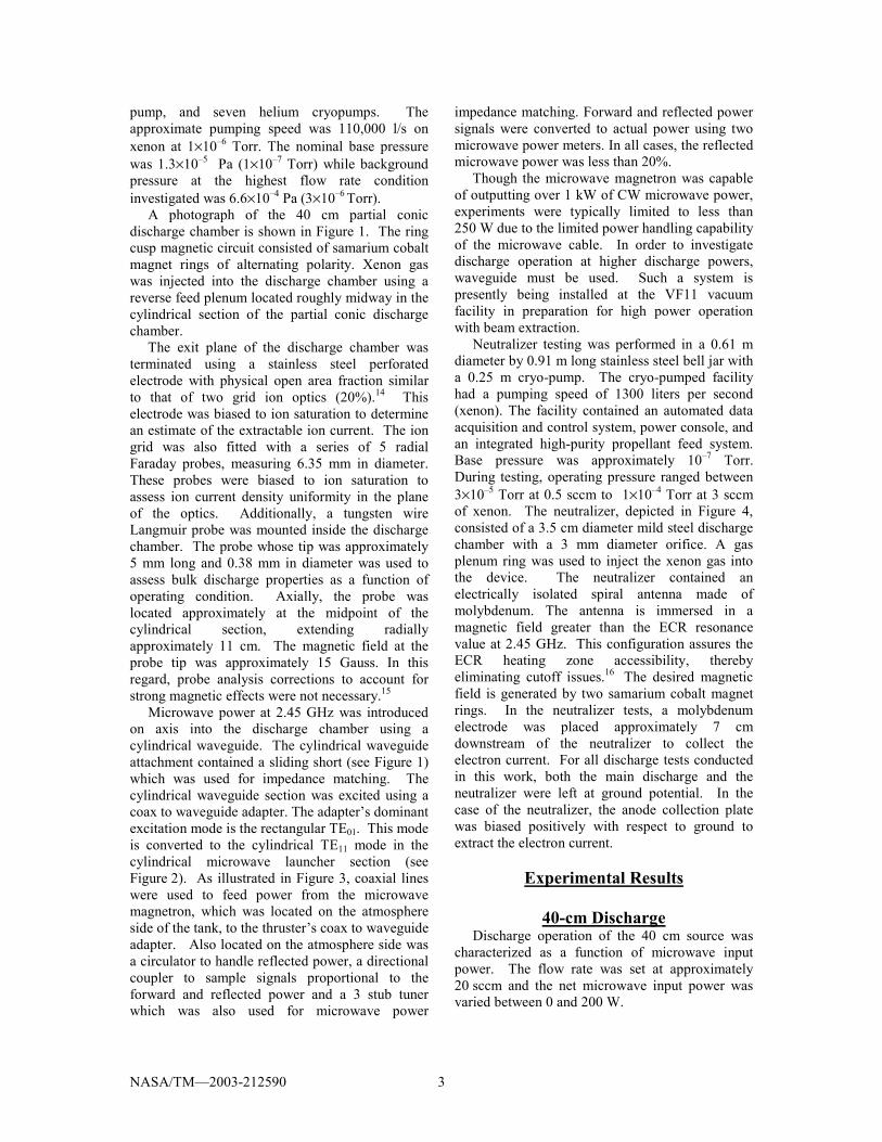
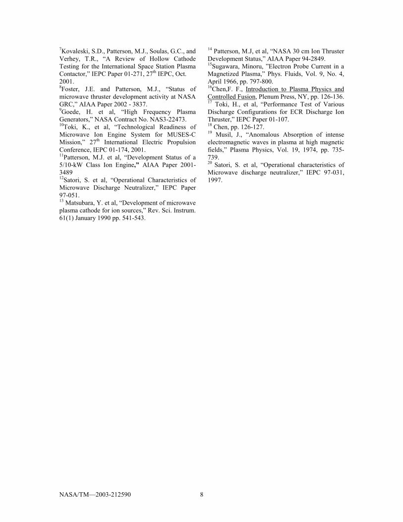
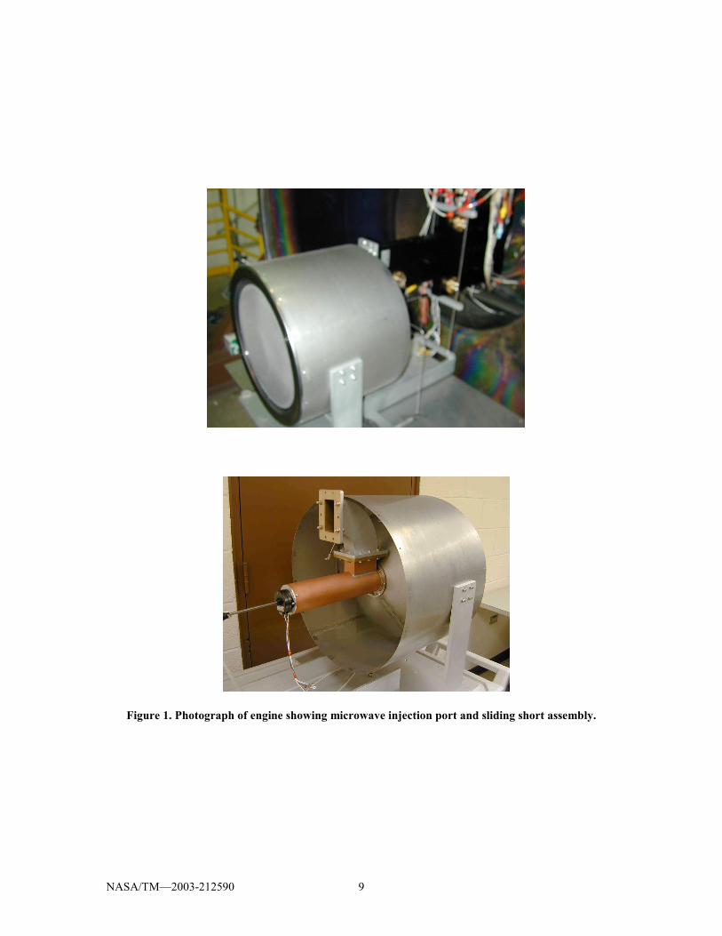
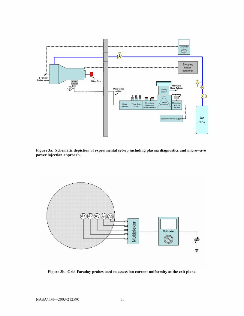
pump, and seven helium cryopumps. The approximate pumping speed was 110,000 l/s on xenon at 1×10�6 Torr. The nominal base pressure was 1.3×10�5 Pa (1×10�7 Torr) while background pressure at the highest flow rate condition investigated was 6.6×10�4 Pa (3×10�6 Torr). A photograph of the 40 cm partial conic discharge chamber is shown in Figure 1. The ring cusp magnetic circuit consisted of samarium cobalt magnet rings of alternating polarity. Xenon gas was injected into the discharge chamber using a reverse feed plenum located roughly midway in the cylindrical section of the partial conic discharge chamber. The exit plane of the discharge chamber was terminated using a stainless steel perforated electrode with physical open area fraction similar to that of two grid ion optics (20%).14 This electrode was biased to ion saturation to determine an estimate of the extractable ion current. The ion grid was also fitted with a series of 5 radial Faraday probes, measuring 6.35 mm in diameter. These probes were biased to ion saturation to assess ion current density uniformity in the plane of the optics. Additionally, a tungsten wire Langmuir probe was mounted inside the discharge chamber. The probe whose tip was approximately 5 mm long and 0.38 mm in diameter was used to assess bulk discharge properties as a function of operating condition. Axially, the probe was located approximately at the midpoint of the cylindrical section, extending radially approximately 11 cm. The magnetic field at the probe tip was approximately 15 Gauss. In this regard, probe analysis corrections to account for strong magnetic effects were not necessary.15 Microwave power at 2.45 GHz was introduced on axis into the discharge chamber using a cylindrical waveguide. The cylindrical waveguide attachment contained a sliding short (see Figure 1) which was used for impedance matching. The cylindrical waveguide section was excited using a coax to waveguide adapter. The adapter�s dominant excitation mode is the rectangular TE01. This mode is converted to the cylindrical TE11 mode in the cylindrical microwave launcher section (see Figure 2). As illustrated in Figure 3, coaxial lines were used to feed power from the microwave magnetron, which was located on the atmosphere side of the tank, to the thruster�s coax to waveguide adapter. Also located on the atmosphere side was a circulator to handle reflected power, a directional coupler to sample signals proportional to the forward and reflected power and a 3 stub tuner which was also used for microwave power
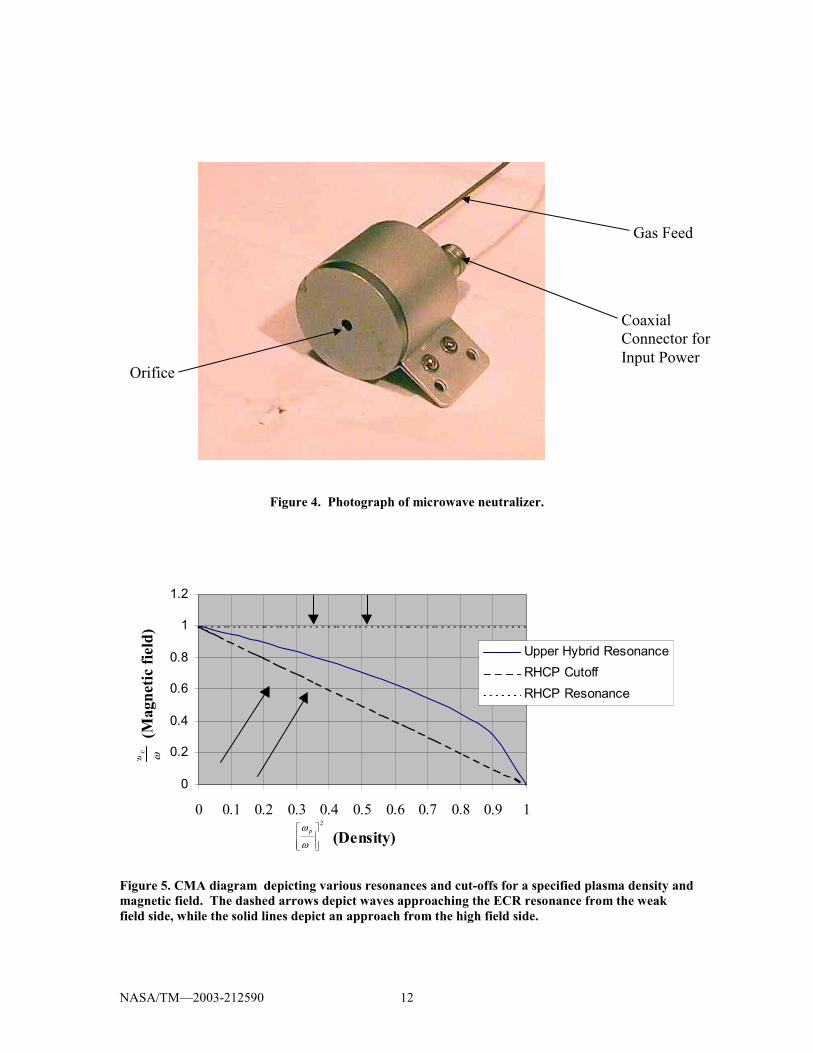
impedance matching. Forward and reflected power signals were converted to actual power using two microwave power meters. In all cases, the reflected microwave power was less than 20%. Though the microwave magnetron was capable of outputting over 1 kW of CW microwave power, experiments were typically limited to less than 250 W due to the limited power handling capability of the microwave cable. In order to investigate discharge operation at higher discharge powers, waveguide must be used. Such a system is presently being installed at the VF11 vacuum facility in preparation for high power operation with beam extraction. Neutralizer testing was performed in a 0.61 m diameter by 0.91 m long stainless steel bell jar with a 0.25 m cryo-pump. The cryo-pumped facility had a pumping speed of 1300 liters per second (xenon). The facility contained an automated data acquisition and control system, power console, and an integrated high-purity propellant feed system. Base pressure was approximately 10�7 Torr. During testing, operating pressure ranged between 3×10�5 Torr at 0.5 sccm to 1×10�4 Torr at 3 sccm of xenon. The neutralizer, depicted in Figure 4, consisted of a 3.5 cm diameter mild steel discharge chamber with a 3 mm diameter orifice. A gas plenum ring was used to inject the xenon gas into the device. The neutralizer contained an electrically isolated spiral antenna made of molybdenum. The antenna is immersed in a magnetic field greater than the ECR resonance value at 2.45 GHz. This configuration assures the ECR heating zone accessibility, thereby eliminating cutoff issues.16 The desired magnetic field is generated by two samarium cobalt magnet rings. In the neutralizer tests, a molybdenum electrode was placed approximately 7 cm downstream of the neutralizer to collect the electron current. For all discharge tests conducted in this work, both the main discharge and the neutralizer were left at ground potential. In the case of the neutralizer, the anode collection plate was biased positively with respect to ground to extract the electron current.
Experimental Results
40-cm Discharge Discharge operation of the 40 cm source was characterized as a function of microwave input power. The flow rate was set at approximately 20 sccm and the net microwave input power was varied between 0 and 200 W.
NASA/TM�2003-212590 4
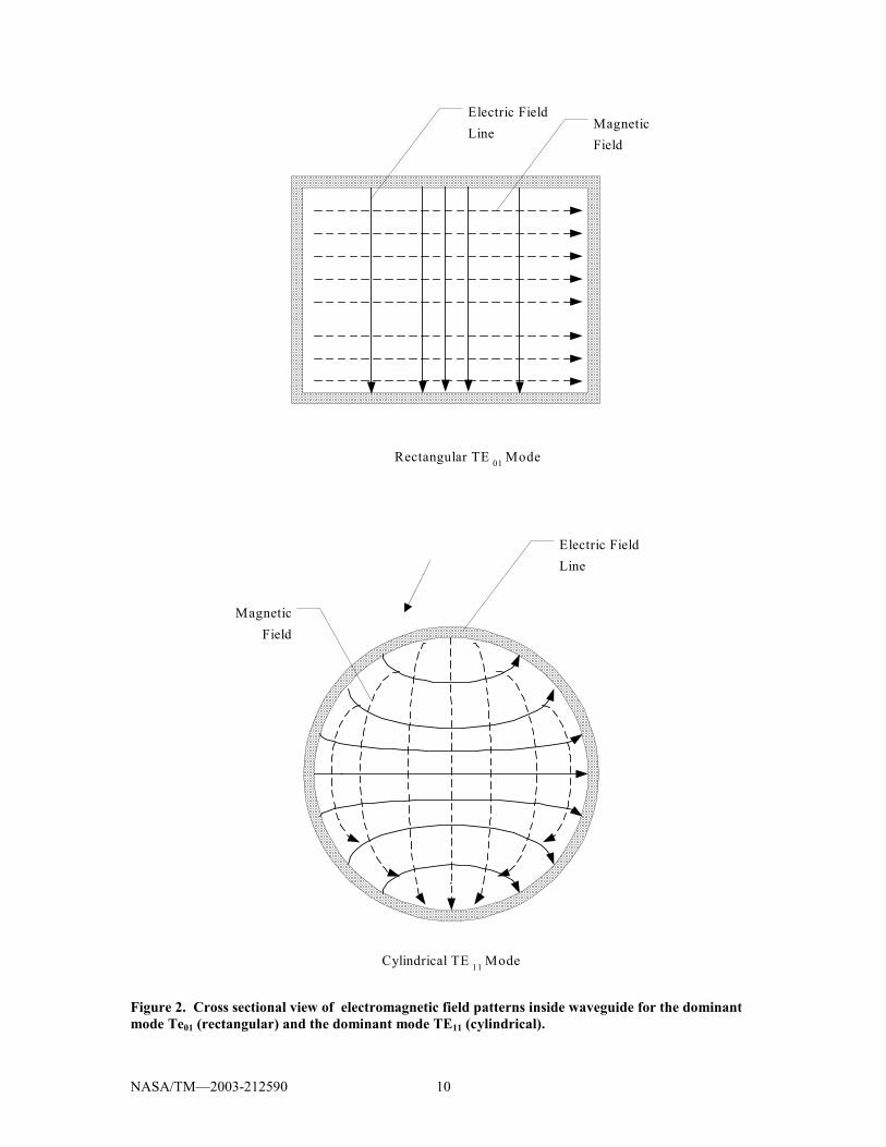
Discharge appearance Because the microwave power was introduced on centerline, the microwave propagation vector k is directed along the discharge axis. In this regard, the vector is parallel to the magnetic field vector at the surface of magnet ring 1, 90- cθ degrees ( cθ =conical section angle) with respect to the magnetic field vector at ring 2, perpendicular to the magnetic field vector at ring 3 and 4 and parallel to the magnetic field vector at the surface of ring 5. The orientation of the propagation vector with respect to the magnetic field vector as well as the vector�s approach direction both determine what type of electron heating if any at all will occur. Figure 5 is a plot of magnetic field strength versus plasma density.16 This plot illustrates two relevant modes of wave absorption (resonance) that can take place in this discharge chamber configuration. The modes include the Right Hand Circularly Polarized mode (RHCP) and the Upper Hybrid frequency mode. If the propagation vector is parallel to the magnetic field vector with the microwave radiation approaching the ECR zone from the high field side, then absorption will always take place as indicated in Figure 5. In this case, the absorption occurs at the RHCP resonance where ceww =µ . Under these conditions, reflected microwave power is minimal and overdense plasma production is possible. Overdense refers to plasma densities in which the plasma frequency exceeds the radiation field frequency. Normally under such conditions, the radiation is simply reflected; however, the dispersion relation for RHCP absorption allows for the propagation of the radiation to the heating site.16 In this regard, though this form of heating is most desirable, it is not usually straightforward to design using permanent magnets-only configurations.17 Conditions for this form of absorption exist at magnet ring # 1. The upper hybrid heating resonance (see Figure 5) condition can be satisfied at rings 2,3 and 4.16 Here, the microwaves approach the resonant zones perpendicular to the magnetic field. Additionally, the k vector approach to the heating zone is from the weak magnetic field side.18 At plasma densities corresponding to plasma frequencies above the microwave excitation frequency, this absorption process should cease. In reality, microwaves can tunnel through the separation between the cutoff and the resonance, thereby allowing for the formation of densities above the critical plasma density (as defined at the condition where plasma frequency =microwave frequency). Absorption at ring 5 is likely due to a combination of Upper
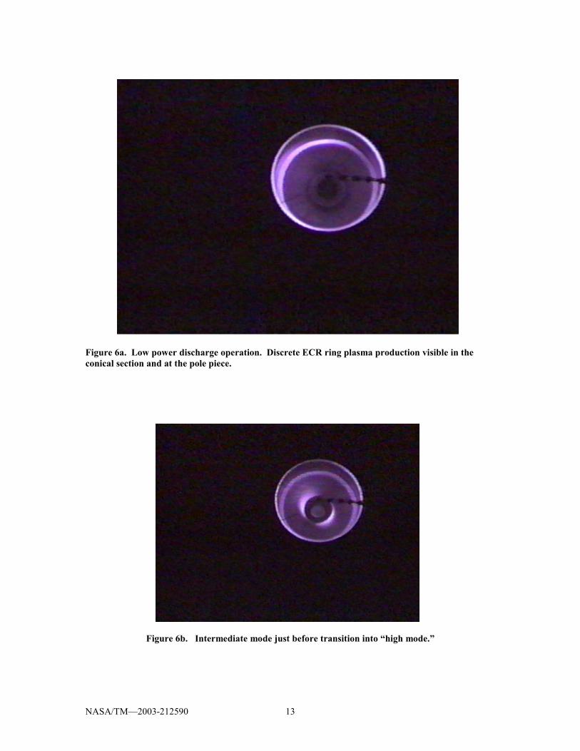
Hybrid frequency production and tunneling to the RHCP resonance. It should be pointed out that microwave radiation not absorbed can be converted to other modes by scattering (which changes the direction of the propagation vector) which are more or less absorbable via the processes described above. The above mentioned absorption processes are useful in interpreting the discharge appearance. The discharge appearance reflects qualitatively what absorption modes are active in the discharge chamber. The 40 cm discharge appears to have several distinct modes of operation. In general at low input discharge powers less than 100 W, the ECR plasma production is localized primarily to the most upstream magnet rings (conical section). In this regard, at low powers Upper Hybrid Resonance can be expected to dominate. As the power approaches 100 W, an annular region near the pole piece magnet ring becomes luminous as well. This low power discharge condition is illustrated in Figure 6 a. In this mode, the discharge overall is fairly dim, but its brightness intensifies with increasing flow rate (internal pressure). This increase is attributed to increased neutral-electron collisions which tends to generate a secondary main discharge plasma in the bulk. In any case, the ECR action locally at the rings is very intense in contrast to the bulk of the discharge. The core plasma of these rings has a white tone, indicating a very intense and localized interaction between very hot electrons and neutral gas. The brightening of the bulk discharge with increasing power in this mode is most due likely to increased production of hot electrons that ultimately diffuse into the bulk and excite/ionize neutrals there. As the microwave power is increased between 100 W and 150 W, an intense plasma glow is observed at the most upstream ring (near waveguide opening) as well. This plasma production is illustrated in Figure 6b. This plasma production mechanism is likely due to RHCP heating. The bulk discharge brightness also increases with the appearance of this new mode. With increasing microwave power >150W, the discharge jumps into an operating mode dominated by volume excitation. In this mode, as shown in Figure 6 c, the distinct ECR plasma production sites at the magnet rings are either absent or completely washed out by the intense volume glow. It is postulated that the jump into this mode is due to RHCP heating and possibly anomalous heating at the most upstream ring.16,19 The presence of plasma at this ring in the intermediate microwave power mode (see Figure 6 b.) provides a medium for the RHCP radiation to couple into.
NASA/TM�2003-212590 5
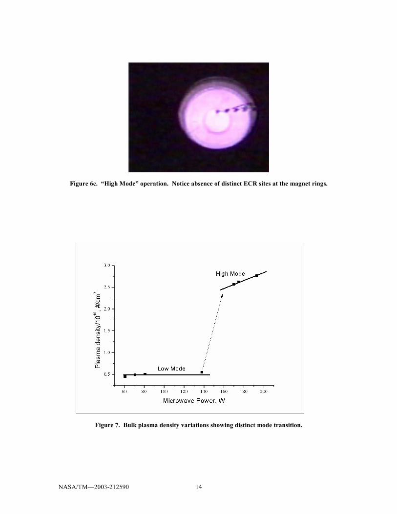
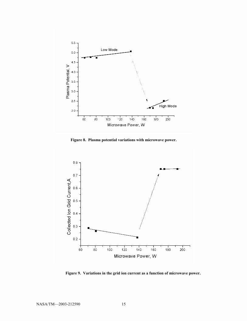
Over-dense plasma production can take place at this ring. Plasma production improves with increasing input microwave power ultimately culminating in the bright discharge shown in Figure 6 c. As will be shown later, this mode is characterized by high density and high uniformity. Discharge Plasma Properties Plasma characteristics such as bulk density, plasma potential and electron temperature were measured over the power range investigated. Average extractable ion current at the discharge chamber exit plane was measured by biasing the ion optics simulator grid. In addition to these measurements, radial button probes were used to measure the ion current uniformity at the exit plane. The plasma measurements acquired were consistent with the visual observations made as net input microwave power was increased from 0 to 200 W. Figure 7 illustrates the variation in the bulk plasma density as measured using a Langmuir probe between 0 and 200 W at a flow-rate of approximately 20 SCCM. As can be observed here, there is a distinct jump in plasma density as microwave power increases appreciably above 140 W. This jump is associated with the visually observed transition to the full volume plasma production mode. In the �low mode�, plasma density increases very slowly with increasing microwave power with an average increase in density of 1.11x 10⁷/(cm3x W). As illustrated in the figure, the plasma density increases by over a factor of 5 as the power increases from 140 W to 170 W. The rate of growth in density with increasing discharge power in the �high mode� is considerably higher than �low mode growth.� Plasma density growth in the �high mode� is nearly linear, increasing 8.45x10⁷/ (cm3x W) in this regime. The plasma potential was observed to drop as the plasma jumps from �low mode� to �high mode�. Figure 8 illustrates the drop of a factor of 2 as power is increased from 0 to 200 W. This transition also proceeds in concert with the increases in plasma density. The measured plasma potential suggests a plasma to screen grid potential difference of order 1 /10 that of the NSTAR thruster. In general reduced plasma potential is desirable for ion thruster operation in that the energy of ions falling out of the discharge into the screen grid is reduced. The electron temperature does not vary appreciably as the plasma transitions from high mode to low mode. Its value was approximately
2 eV over the power range investigated here at this flow rate. The relative flatness in the electron temperature with increasing input power suggests that the improved discharge performance in the �high mode� is not so much a consequence of better heating of the electrons, but more so an increase in the number of regions where plasma production is taking place. It is postulated that RHCP absorption at ring 1 may play a major role in the improved discharge characteristics in the �high mode�. The plasma measurements were point measurements in the bulk plasma that should be representative of volume plasma processes. In this regard, the gradients measured as power is increased represent improved volume plasma production with the transition into the �high mode�. The highest plasma density condition observed in this mode corresponded to a plasma density 50% less than the cut-off frequency 7.45×10¹⁰#/cm3, indicating that the plasma density was still below cut-off. Near the rings, the plasma density may be much larger than that measured by the Langmuir probe which sampled the bulk of the discharge, near centerline. In this regard, because the microwave frequency was greater than the cut-off frequency at these plasma densities, microwave power can indeed propagate through the bulk and be absorbed at the ECR sites. Given the slope of change in plasma density with increasing discharge power, it is expected that the cutoff density would be obtained in the bulk plasma at a microwave input power of 700 W. It follows then that increasing the input microwave power should bring about further increases in the plasma density. This study was limited to operating microwave input powers <250W due to coax cable over-heating which tended to fail at power levels above 250 W. The ion current to the biased ion optics simulator grid also increased significantly as the discharge transitioned from �low mode� to �high mode.� Figure 9 illustrates variations in the ion current collected at the grid at roughly 20 SCCM. Behavior similar to that observed in the plasma density and plasma potential with increasing microwave power is observed but there are some differences. At this fixed flow rate, the grid current in �high mode� did not increase appreciably with increasing discharge power. The grid current�s average value was approximately 0.75 A. This result suggests that the radial plasma density distribution might be changing with increasing microwave power. The density may be increasing in the bulk, and decreasing in the wings so that the net change in current collected at the grid is nearly zero.
NASA/TM�2003-212590 6
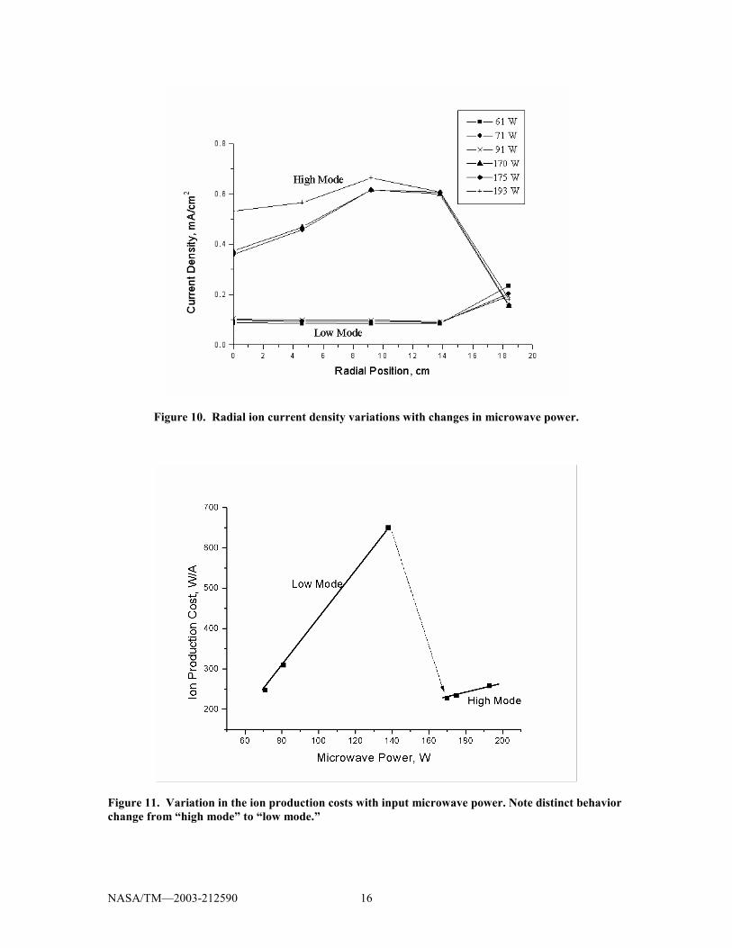
Changes in the current density distribution as measured using radial probes mounted on the ion optics simulation electrode seem to support this notion. Figure 10 illustrates variations in the ion current density profile as the plasma goes from �high mode� to �low mode�. Clearly there is a distinct change in the ion current distribution. Indeed, the plasma density profile becomes very uniform as the plasma proceeds into the �high mode.� The absence of a peaked current density profile is highly desirable from an ion extraction standpoint. In the �low mode� the ion current density is peaked at the edges, near the discharge chamber walls. The measured current density distribution is consistent with the visual observations. In the �low mode�, the most prominent plasma excitation occurs at the rings. It is therefore to be expected that the current density would be peaked at the wings in the �low mode.� The observed volume excitation in the �high mode� is consistent with the improved current density uniformity. In this investigation, grid currents up to 0.82 A were achieved. This grid current was obtained at 12.5 SCCM. This grid current is within 7 percent of the equivalent Amperes of input xenon gas. This data suggests an uncorrected utilization of order 93%, suggesting high ionization capability. This collected grid current is consistent with an average plasma approximately 75% of cut-off plasma density. Because bulk plasma densities were of order a factor of 2 times lower than the cut-off, the large current measured at the grids may be due to an increase in the electron temperature near the grid. This data suggests that large increases in discharge power beyond 200 W may not be necessary to achieve the target of a 1 A ion beam. The discharge efficiency as characterized by ion production costs is plotted in Figure 11 for the 20 sccm flow condition. As can be seen here, there is also a distinct change in functional behavior as power is increased. The �low mode� is characterized as high ion production costs with a larger slope indicating higher losses with increasing input power. The sudden jump to the �high mode� is characterized by reduced ion production costs (~200 W/A) and a much shallower slope indicating discharge efficiency with increasing power degrades at a lesser rate with increasing power than that observed in the �low mode.� It is expected that the ion production costs can be improved by either increasing the microwave frequency or by increasing the input power to achieve anomalous heating.19 Altogether, the data indicates that high mode operation is best for thruster operation. To fully
characterize the source, higher power levels must be investigated. Presently, the microwave coax feed approach is being abandoned to be replaced by an all-wave-guide transmission set-up. This approach should allow for over 1 kW of power to be deposited into the discharge. If cut-off in the bulk plasma is reached or exceeded by anomalous heating then a minimum of 1.1 A should be available for extraction.
Preliminary Neutralizer Characterization
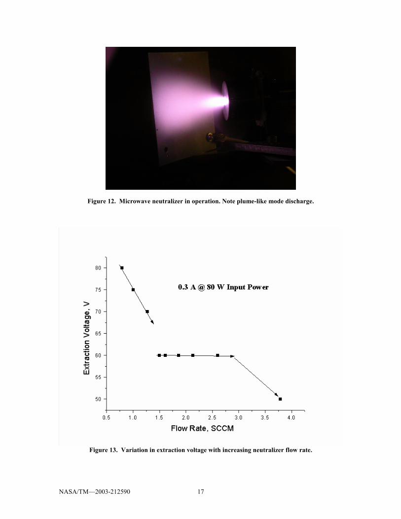
The microwave neutralizer featuring an internal antenna also operating at 2.45 GHz was also characterized. The primary objective of this investigation was to minimize required neutralizer flow rate and electron extraction voltage while at the same time maximize the output electron emission current. Minimizing the gas flow rate improves specific impulse and overall thruster efficiency. Such reductions also decrease the population of those neutrals that travel to the ion optics region and participate in charge exchange collisions. Reducing the extraction or neutralizer coupling voltage minimizes neutralizer erosion rates by reducing energy at which ions created in the neutralizer plasma impact the device. In these experiments, a planar anode, placed downstream of the neutralizer was used to extract the electron current. Figure 12 depicts qualitative features of the neutralizer�s operation. In general, as illustrated in the photograph, the neutralizer operates in the so-called plume mode. This mode of operation is similar to that observed with similar devices. In general additional ionization of gas escaping from the neutralizer contributes to the collected electron current. Such ionization generates a plasma bridge which reduces the impedance between the device and the anode. This plume ionization necessitates some minimum voltage drop between the neutralizer and anode (or ion beam in the case of an actual ion thruster application). In this work, it was found that 50-56V was the minimum voltage range at which appreciable electron current (>0.3 A) could be extracted. Figure 13 illustrates variations in extraction voltage between the neutralizer and the anode as a function of xenon flow rate. This data was obtained by fixing the net input microwave power to approximately 80 W and setting the electron emission current to 0.3 A. As can be seen in the Figure, the lowest impedance occurs at the highest
NASA/TM�2003-212590 7
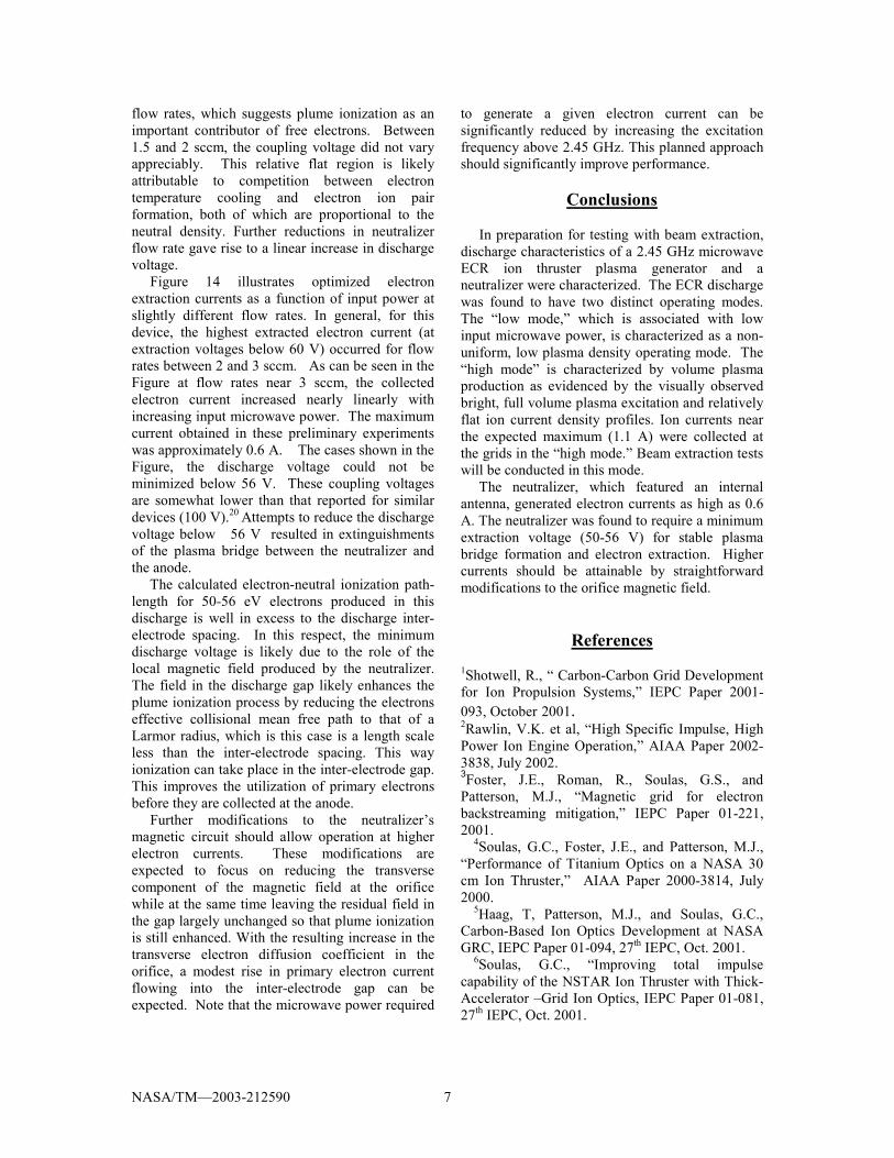
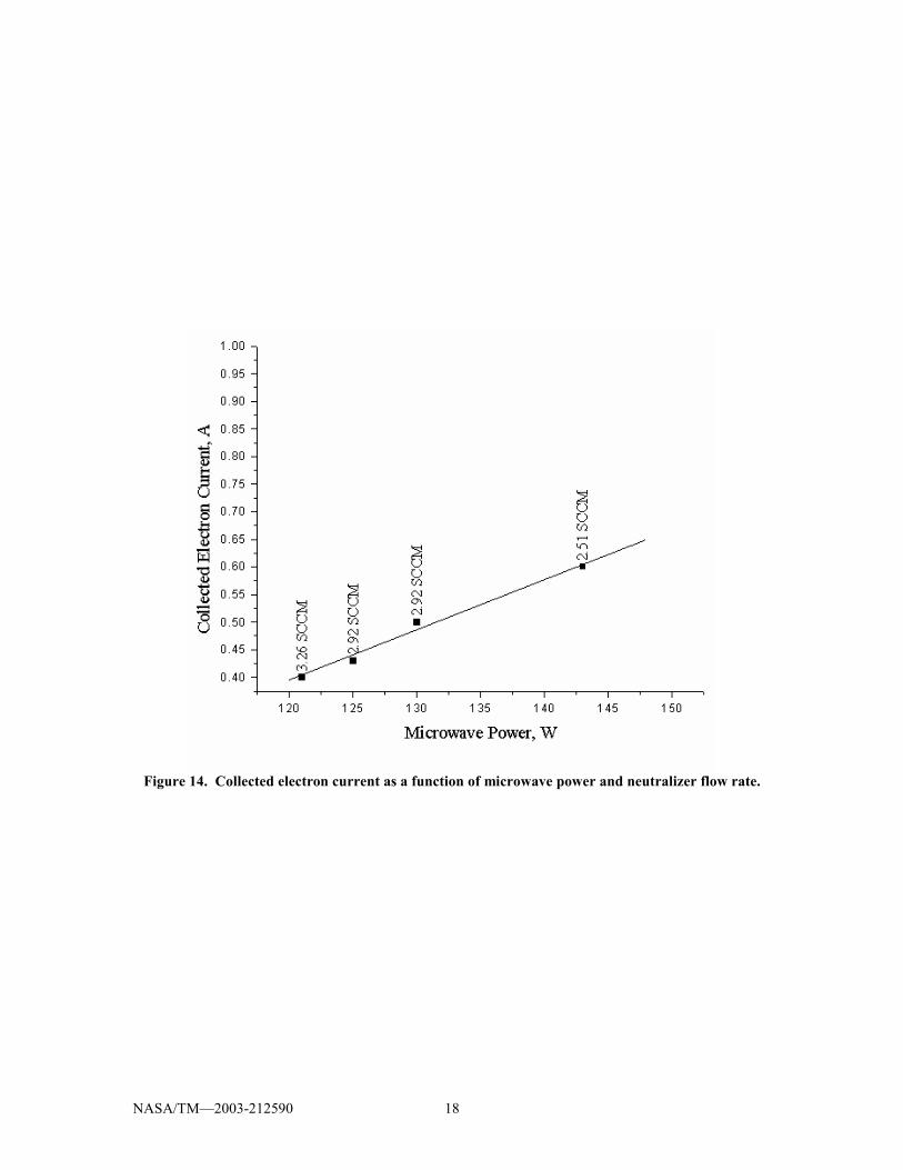
flow rates, which suggests plume ionization as an important contributor of free electrons. Between 1.5 and 2 sccm, the coupling voltage did not vary appreciably. This relative flat region is likely attributable to competition between electron temperature cooling and electron ion pair formation, both of which are proportional to the neutral density. Further reductions in neutralizer flow rate gave rise to a linear increase in discharge voltage. Figure 14 illustrates optimized electron extraction currents as a function of input power at slightly different flow rates. In general, for this device, the highest extracted electron current (at extraction voltages below 60 V) occurred for flow rates between 2 and 3 sccm. As can be seen in the Figure at flow rates near 3 sccm, the collected electron current increased nearly linearly with increasing input microwave power. The maximum current obtained in these preliminary experiments was approximately 0.6 A. The cases shown in the Figure, the discharge voltage could not be minimized below 56 V. These coupling voltages are somewhat lower than that reported for similar devices (100 V).20 Attempts to reduce the discharge voltage below 56 V resulted in extinguishments of the plasma bridge between the neutralizer and the anode. The calculated electron-neutral ionization path-length for 50-56 eV electrons produced in this discharge is well in excess to the discharge inter-electrode spacing. In this respect, the minimum discharge voltage is likely due to the role of the local magnetic field produced by the neutralizer. The field in the discharge gap likely enhances the plume ionization process by reducing the electrons effective collisional mean free path to that of a Larmor radius, which is this case is a length scale less than the inter-electrode spacing. This way ionization can take place in the inter-electrode gap. This improves the utilization of primary electrons before they are collected at the anode. Further modifications to the neutralizer�s magnetic circuit should allow operation at higher electron currents. These modifications are expected to focus on reducing the transverse component of the magnetic field at the orifice while at the same time leaving the residual field in the gap largely unchanged so that plume ionization is still enhanced. With the resulting increase in the transverse electron diffusion coefficient in the orifice, a modest rise in primary electron current flowing into the inter-electrode gap can be expected. Note that the microwave power required
to generate a given electron current can be significantly reduced by increasing the excitation frequency above 2.45 GHz. This planned approach should significantly improve performance.
Conclusions
In preparation for testing with beam extraction, discharge characteristics of a 2.45 GHz microwave ECR ion thruster plasma generator and a neutralizer were characterized. The ECR discharge was found to have two distinct operating modes. The �low mode,� which is associated with low input microwave power, is characterized as a non-uniform, low plasma density operating mode. The �high mode� is characterized by volume plasma production as evidenced by the visually observed bright, full volume plasma excitation and relatively flat ion current density profiles. Ion currents near the expected maximum (1.1 A) were collected at the grids in the �high mode.� Beam extraction tests will be conducted in this mode. The neutralizer, which featured an internal antenna, generated electron currents as high as 0.6 A. The neutralizer was found to require a minimum extraction voltage (50-56 V) for stable plasma bridge formation and electron extraction. Higher currents should be attainable by straightforward modifications to the orifice magnetic field.
References
1Shotwell, R., � Carbon-Carbon Grid Development for Ion Propulsion Systems,� IEPC Paper 2001-093, October 2001. 2Rawlin, V.K. et al, �High Specific Impulse, High Power Ion Engine Operation,� AIAA Paper 2002-3838, July 2002. 3Foster, J.E., Roman, R., Soulas, G.S., and Patterson, M.J., �Magnetic grid for electron backstreaming mitigation,� IEPC Paper 01-221, 2001.
4Soulas, G.C., Foster, J.E., and Patterson, M.J., �Performance of Titanium Optics on a NASA 30 cm Ion Thruster,� AIAA Paper 2000-3814, July 2000.
5Haag, T, Patterson, M.J., and Soulas, G.C., Carbon-Based Ion Optics Development at NASA GRC, IEPC Paper 01-094, 27th IEPC, Oct. 2001.
6Soulas, G.C., �Improving total impulse capability of the NSTAR Ion Thruster with Thick-Accelerator �Grid Ion Optics, IEPC Paper 01-081, 27th IEPC, Oct. 2001.
NASA/TM�2003-212590 8
7Kovaleski, S.D., Patterson, M.J., Soulas, G.C., and Verhey, T.R., �A Review of Hollow Cathode Testing for the International Space Station Plasma Contactor,� IEPC Paper 01-271, 27th IEPC, Oct. 2001. 8Foster, J.E. and Patterson, M.J., �Status of microwave thruster development activity at NASA GRC,� AIAA Paper 2002 - 3837. 9Goede, H. et al, �High Frequency Plasma Generators,� NASA Contract No. NAS3-22473. 10Toki, K., et al, �Technological Readiness of Microwave Ion Engine System for MUSES-C Mission,� 27th International Electric Propulsion Conference, IEPC 01-174, 2001. 11Patterson, M.J. et al, �Development Status of a 5/10-kW Class Ion Engine,� AIAA Paper 2001-3489 12Satori, S. et al, �Operational Characteristics of Microwave Discharge Neutralizer,� IEPC Paper 97-051. 13 Matsubara, Y. et al, �Development of microwave plasma cathode for ion sources,� Rev. Sci. Instrum. 61(1) January 1990 pp. 541-543.
14 Patterson, M.J, et al, �NASA 30 cm Ion Thruster Development Status,� AIAA Paper 94-2849. 15Sugawara, Minoru, �Electron Probe Current in a Magnetized Plasma,� Phys. Fluids, Vol. 9, No. 4, April 1966, pp. 797-800. 16Chen,F. F., Introduction to Plasma Physics and Controlled Fusion, Plenum Press, NY, pp. 126-136. 17 Toki, H., et al, �Performance Test of Various Discharge Configurations for ECR Discharge Ion Thruster,� IEPC Paper 01-107. 18 Chen, pp. 126-127. 19 Musil, J., �Anomalous Absorption of intense electromagnetic waves in plasma at high magnetic fields,� Plasma Physics, Vol. 19, 1974, pp. 735-739. 20 Satori, S. et al, �Operational characteristics of Microwave discharge neutralizer,� IEPC 97-031, 1997.
NASA/TM�2003-212590 9
Figure 1. Photograph of engine showing microwave injection port and sliding short assembly.
NASA/TM�2003-212590 10
Figure 2. Cross sectional view of electromagnetic field patterns inside waveguide for the dominant mode Te01 (rectangular) and the dominant mode TE11 (cylindrical).
Electric FieldLine
MagneticField
.
.Electric FieldLine
MagneticField
Rectangular TE 01 Mode
Cylindrical TE 11 Mode
NASA/TM�2003-212590 11
Figure 3a. Schematic depiction of experimental set-up including plasma diagnostics and microwave power injection approach.
Figure 3b. Grid Faraday probes used to assess ion current uniformity at the exit plane.
SteppingMotor
controller
Coax Adapter
�dummyLoad?�
MicrowaveLauncherSection
3 PortCirculatorTriple Stub
Tuner
DirectionalCoupler w/
Diode Detectors
Microwave Diode Detector
Magnetron
Microwave Power Supply
Multimeter
5 FaradayProbes on grid
Water-cooledcabling
Xetank
FC
FICoaxAdapter
TC1
Sliding Short
SteppingMotor
controller
Coax Adapter
�dummyLoad?�
MicrowaveLauncherSection
3 PortCirculatorTriple Stub
Tuner
DirectionalCoupler w/
Diode Detectors
Microwave Diode Detector
Magnetron
Coax Adapter
�dummyLoad?�
MicrowaveLauncherSection
3 PortCirculator
3 PortCirculatorTriple Stub
TunerTriple Stub
Tuner
DirectionalCoupler w/
Diode Detectors
DirectionalCoupler w/
Diode Detectors
Microwave Diode Detector
Magnetron
Microwave Power Supply
MultimeterMultimeter
5 FaradayProbes on grid
Water-cooledcabling
Xetank
FC
FICoaxAdapter
TC1
TC1
Sliding Short
NASA/TM�2003-212590 12
Figure 4. Photograph of microwave neutralizer.
Figure 5. CMA diagram depicting various resonances and cut-offs for a specified plasma density and magnetic field. The dashed arrows depict waves approaching the ECR resonance from the weak field side, while the solid lines depict an approach from the high field side.
Gas Feed
Orifice
Coaxial Connector for Input Power
0
0.2
0.4
0.6
0.8
1
1.2
0 0.1 0.2 0.3 0.4 0.5 0.6 0.7 0.8 0.9 1
(Density)
(Mag
netic
fiel
d)
Upper Hybrid ResonanceRHCP CutoffRHCP Resonance
ωωc
2
ω
ω p
NASA/TM�2003-212590 13
Figure 6a. Low power discharge operation. Discrete ECR ring plasma production visible in the conical section and at the pole piece.
Figure 6b. Intermediate mode just before transition into �high mode.�
NASA/TM�2003-212590 14
Figure 6c. �High Mode� operation. Notice absence of distinct ECR sites at the magnet rings.
Figure 7. Bulk plasma density variations showing distinct mode transition.
NASA/TM�2003-212590 15
Figure 8. Plasma potential variations with microwave power.
Figure 9. Variations in the grid ion current as a function of microwave power.
NASA/TM�2003-212590 16
Figure 10. Radial ion current density variations with changes in microwave power.
Figure 11. Variation in the ion production costs with input microwave power. Note distinct behavior change from �high mode� to �low mode.�
NASA/TM�2003-212590 17
Figure 12. Microwave neutralizer in operation. Note plume-like mode discharge.
Figure 13. Variation in extraction voltage with increasing neutralizer flow rate.
NASA/TM�2003-212590 18
Figure 14. Collected electron current as a function of microwave power and neutralizer flow rate.
This publication is available from the NASA Center for AeroSpace Information, 301–621–0390.
REPORT DOCUMENTATION PAGE
2. REPORT DATE
19. SECURITY CLASSIFICATION OF ABSTRACT
18. SECURITY CLASSIFICATION OF THIS PAGE
Public reporting burden for this collection of information is estimated to average 1 hour per response, including the time for reviewing instructions, searching existing data sources,gathering and maintaining the data needed, and completing and reviewing the collection of information. Send comments regarding this burden estimate or any other aspect of thiscollection of information, including suggestions for reducing this burden, to Washington Headquarters Services, Directorate for Information Operations and Reports, 1215 JeffersonDavis Highway, Suite 1204, Arlington, VA 22202-4302, and to the Office of Management and Budget, Paperwork Reduction Project (0704-0188), Washington, DC 20503.
NSN 7540-01-280-5500 Standard Form 298 (Rev. 2-89)Prescribed by ANSI Std. Z39-18298-102
Form Approved
OMB No. 0704-0188
12b. DISTRIBUTION CODE
8. PERFORMING ORGANIZATION REPORT NUMBER
5. FUNDING NUMBERS
3. REPORT TYPE AND DATES COVERED
4. TITLE AND SUBTITLE
6. AUTHOR(S)
7. PERFORMING ORGANIZATION NAME(S) AND ADDRESS(ES)
11. SUPPLEMENTARY NOTES
12a. DISTRIBUTION/AVAILABILITY STATEMENT
13. ABSTRACT (Maximum 200 words)
14. SUBJECT TERMS
17. SECURITY CLASSIFICATION OF REPORT
16. PRICE CODE
15. NUMBER OF PAGES
20. LIMITATION OF ABSTRACT
Unclassified Unclassified
Technical Memorandum
Unclassified
National Aeronautics and Space AdministrationJohn H. Glenn Research Center at Lewis FieldCleveland, Ohio 44135–3191
1. AGENCY USE ONLY (Leave blank)
10. SPONSORING/MONITORING AGENCY REPORT NUMBER
9. SPONSORING/MONITORING AGENCY NAME(S) AND ADDRESS(ES)
National Aeronautics and Space AdministrationWashington, DC 20546–0001
Available electronically at http://gltrs.grc.nasa.gov
October 2003
NASA TM—2003-212590AIAA–2003–5012
E–14147
WBS–22–755–70–04
24
Discharge Characterization of 40 cm-Microwave ECR Ion Source and Neutralizer
John E. Foster, Michael J. Patterson, and Melissa Britton
Ion thruster; Microwave; Plasma; Neutralizer
Unclassified -UnlimitedSubject Categories: 20 and 75 Distribution: Nonstandard
Prepared for the 39th Joint Propulsion Conference and Exhibit cosponsored by the AIAA, ASME, SAE, and ASEE,Huntsville, Alabama, July 20–23, 2003. John E. Foster and Michael J. Patterson, NASA Glenn Research Center; andMelissa Britton, QSS Group, Inc., Cleveland, Ohio 44135. Responsible person, John E. Foster, organization code 5430,216–433–6131.
Discharge characteristics of a 40 cm, 2.45 GHz Electron Cyclotron Resonance (ECR) ion thruster discharge chamber andneutralizer were acquired. Thruster bulk discharge plasma characteristics were assessed using a single Langmuir probe.Total extractable ion current was measured as a function of input microwave power and flow rate. Additionally, radial ioncurrent density profiles at the thruster’s exit plane were characterized using five equally spaced Faraday probes. Distinctlow and high density operating modes were observed as discharge input power was varied from 0 to 200 W. In the highmode, extractable ion currents as high as 0.82 A were measured. Neutralizer emission current was characterized as afunction of flow rate and microwave power. Neutralizer extraction currents as high as 0.6 A were measured.