disclaimer - seoul national...
TRANSCRIPT

저 시-비 리- 경 지 2.0 한민
는 아래 조건 르는 경 에 한하여 게
l 저 물 복제, 포, 전송, 전시, 공연 송할 수 습니다.
다 과 같 조건 라야 합니다:
l 하는, 저 물 나 포 경 , 저 물에 적 된 허락조건 명확하게 나타내어야 합니다.
l 저 터 허가를 면 러한 조건들 적 되지 않습니다.
저 에 른 리는 내 에 하여 향 지 않습니다.
것 허락규약(Legal Code) 해하 쉽게 약한 것 니다.
Disclaimer
저 시. 하는 원저 를 시하여야 합니다.
비 리. 하는 저 물 리 목적 할 수 없습니다.
경 지. 하는 저 물 개 , 형 또는 가공할 수 없습니다.

Master’s Thesis of Engineering
Effect of CO2 Laser on Silicon
Carbide (SiC) Polishing
실리콘 카바이드에 대한 CO2 레이저 연마의 효과
August 2019
Graduate School of Seoul National University
College of Engineering
Department of Mechanical & Aerospace Engineering
Pablo Antonio Abrego Serrano

Effect of CO2 Laser on Silicon
Carbide (SiC) Polishing
Academic advisor Prof. Sung-Hoon Ahn
Submitting a master’s thesis of Engineering
April 2019
Graduate School of Seoul National UniversityCollege of Engineering
Pablo Antonio Abrego Serrano
Confirming the master’s thesis written by
Pablo Antonio Abrego SerranoJune 2019
Chair Kunwoo Lee (Seal)
Vice Chair Sung-Hoon, Ahn (Seal)
Examiner Suk Won Cha (Seal)

i
Abstract
Effect of CO2 Laser on Silicon
Carbide (SiC) Polishing
Pablo Antonio Abrego Serrano
Department of Mechanical and Aerospace Engineering
The Graduate School
Seoul National University
Silicon carbide (SiC) has long been recognized as an excellent
material for high performance optical applications because it offers
many advantages over other commonly used glasses and metals.
Some of the superior attributes of SiC include extremely high
specific stiffness (E/ρ), high thermal conductivity and outstanding
dimensional stability.
The effect of and CO2 laser and its tool path on silicon carbide
(SiC) were investigated. The process started by creating Laser
induced cracks on the desired pattern. Subsequently, laser assisted
polishing was conducted on the same tool path. The surface showed
a sharp difference in material removal in the areas with laser
induced cracks and in areas with no cracks. This high difference in
material removal was used to generate macro and micro patterns.
Grooves from 2 mm to 200μm in width and 5μm to 20μm depth
were successfully generated. Moreover, this process was used to
machine a spherical concave mirror that was later used as part of a
Newtonian telescope.
Keyword : Polishing, Hybrid, Material Removal Rate (MRR),
Patterning

ii
Student Number : 2017-26782

iii
Table of Contents
Chapter 1. Introduction........................................................ 1
1.1 Purpose of Research ................................................................................1
1.2 Surface Texture on Ceramics .................................................................3
1.2 Hybrid Machining Processes ...................................................................3
Chapter 2. Experiment Set up.............................................. 5
2.1 Hardware Set-Up ....................................................................................5
Chapter 3. Material Removal Rate........................................ 7
3.1 CO2 Laser Generated Cracks .................................................................7
3.2 Experiment Design ...................................................................................9
3.3 Material Removal Measurement and Results .......................................12
Chapter 4. Macro/Micro Channels .......................................17
4.1 Macro/Micro Channels Design...............................................................17
4.2 Tool Size Effect ......................................................................................19
4.3 Variable Width Channel ..........................................................................20
4.4 Tool Path Effect......................................................................................22
Chapter 5. Newtonian Telescope .......................................25
5.1 Mirror Design and Fabrication...............................................................25
5.2 Reflector of Newtonian Telescope........................................................28
Chapter 6. Conclusion.........................................................31
Bibliography.......................................................................32
Abstract in Korean.............................................................35

iv

v
List of Tables
Table 1. Mechanical Properties of Silicon Carbide (SiC).......1
Table 2. Experiment parameters..............................................12
Table 3. Mirror parameters ......................................................30

vi
List of Figures
Figure 1. Silicon Carbide Mirrors...............................................2
Figure 2. Schematic diagram of the ‘laser + polishing’ hybrid
process [22] .........................................................................6
Figure 3. Microscope image of a SiC sample (a) polished for
10 minutes and (b) polished for 60 minutes.......................7
Figure 4. Microscope image of a SiC sample (a) laser cracked
and (b) laser cracked + 60 minutes of polishing ...............8
Figure 5. Microscope image showing difference between
laser cracked surface and non-cracked.............................9
Figure 6. Diagram of MRR experiment’s tool path .................10
Figure 7. (a) conventional polishing (P), (b) laser assisted
polishing (LAP), Pre-cracks + laser assisted polishing
(CLAP), Re-cracking process [22]...................................11
Figure 8. Diagram of the measurement of surface profile.....13
Figure 9. Surface profile data for CLAP process for the 4
different measured directions............................................13
Figure 10. Surface profiler data for the 4 different performed
experiments.........................................................................14
Figure 11. Surface profile data for re-cracking experiment
over prolonged period of time...........................................15
Figure 12. (a) Deepest polished point and (b) MRR of 4
different experiments.........................................................17
Figure 13. Diagram of the machined patterns.........................19
Figure 14. (a) 3D surface and (b) surface profile data of
generated pattern ...............................................................21
Figure 15. (a) tool design for MRR experiment and failed
pattern machining, and (b) modified tool for patterning..22

vii
Figure 16. (a) 3D surface and (b) surface profile data of
generated pattern with modified tool................................23
Figure 17. (a) 3D surface and (b) surface profile data of
generated variable width pattern with modified tool.......25
Figure 18. Real image of (a) constant width channels and (b)
variable width channels......................................................25
Figure 19. Modified raster tool path width ............................26
Figure 20. (a) 3D surface and (b) surface profile data of
generated variable width pattern with modified tool and
modified raster tool path....................................................27
Figure 21. Spherical mirror fabrication diagram.....................29
Figure 22. Commercial Newtonian telescope’s mirror and
holder...................................................................................30
Figure 23. Fabricated concave spherical mirror by hybrid
process ................................................................................30
Figure 24. Surface profile of commercial mirror and
fabricated mirror by hybrid process .................................31
Figure 25. Newtonian telescope’s principle ............................32
Figure 26. Fabricated SiC mirror and 3D printed jig..............32
Figure 27. (a) image taken at early stage of polishing, and (b)
image of mirror with curvature of 2200 mm radius.........33

1
Chapter 1. Introduction
1.1. Purpose of Research
Some of the preferred characteristics for an optical mirror material
include low density, high elastic modulus, low coefficient of thermal
expansion, and high thermal conductivity [1-5]. Depending upon
the specific use, the fracture toughness and stress corrosion
constant, which control slow crack growth and long-term reliability
under static or dynamic loads during manufacturing and use, may
also be important.
Silicon carbide (SiC) has long been recognized as an excellent
material for high performance optical applications because it offers
many advantages over other commonly used glasses and metals
[6-8]. Some of the superior attributes of SiC include extremely
high specific stiffness (E/ρ), high thermal conductivity and
outstanding dimensional stability as shown in Table 1 [1].
Table 1. Mechanical Properties of Silicon Carbide (SiC)
Parameter [unit] Value
Density (gm/cc) 3.1
Porosity (%) 0
Flexural Strength (MPa) 550
Elastic Modulus (GPa) 410
Compressive Strength (MPa) 3900
Hardness (Kg/mm2) 2800
Fracture Toughness (MPa•m1/2) 4.6
Maximum Use Temperature (°C ) 1650
Thermal Conductivity (W/m•°K ) 120
Coefficient of Thermal Expansion (10–6/°C) 4
Specific Heat (J/Kg•°K ) 750
Hardness (Kg/mm2) 2800
.
Because silicon carbide is an extremely hard and strong
material, the precision machining required for both shaping and light

2
weighting is typically performed with diamond tooling on very stiff
high quality machine tools (e.g., precision CNC equipment) using
slow (comparatively speaking) material removal profiles.
Conventional finishing processes (lapping, polishing) of SiC
substrates also proceed much more slowly when compared to
conventional optical materials due to the hardness and fracture
toughness of the material. Even with the necessary use of diamond
abrasive, the material removal rate for SiC is approximately 1/35th
that of fused silica and less than 1/50th that of Zerodur ① .
Compounding these issues, any light weighting of the substrate can
induce additional difficulties for achieving high quality optical
surface profiles (< λ/10).
Figure 1. Silicon Carbide Mirrors
Achieving such a high level of surface profile accuracy is often
problematic, as the skilled optician requires multiple iterations of
the polishing process to overcome such difficulties as print-through,
accommodate unusual component geometries, etc. As a result, it is
normally expensive to produce a light weighted, super-polished SiC
① lithium-aluminosilicate glass-ceramic produced by Schott AG since
1968. It has been used for a number of very large telescope mirrors
including Keck I, Keck II, and SOFIA.

3
substrate, and the lead-time for obtaining a finished substrate can
be several months. Thus, although SiC appears to be an ideal optical
material from a material properties standpoint, the cost and lead-
time associated with the preliminary shaping, light weighting, and
optical finishing of the SiC substrate have heretofore been major
impediments to the widespread use of the material in optical
systems.
1.2. Surface Texture on Ceramics
Advanced ceramics are preferable for kinds of strategic application,
low thermal conductivity, low coefficient of friction, excellent
corrosion and wear resistance, high fracture toughness, and good
thermal shock resistance make Silicon Carbide suitable for the use
in engineering applications.
In order to improve tribological properties of ceramic surface,
surface textures as an effective approach have been applied in
bearings, mechanical seals and engine cylinder liners. Meanwhile,
because of excellent tribological, electrical, and optical properties,
ceramics with textures are also widely used in engineering
applications such as cutting tools, solar receiver applications, and
electronic component. However, the properties of ceramics have
difficulties with respect to its engineering fabrication through
traditional approaches.
Tires in automobiles are equipped with sophisticated surface
textures to control friction for safe driving under various road
conditions. Laser pre-treatment has been previously used to
improve the tribological properties of ceramic surfaces [9-11],
1.3. Hybrid Machining Processes
Hybrid machining is combine different machining processes to
manufacture components with a better machining performance. The
objective of hybridizing processes is the positive effect of the
hybrid process is more than double advantages of the single

4
processes [12-16]. Hybrid processes developing due to the advent
of novel materials with extreme properties, requirements of
enhanced machining precision and complex shaped parts which
earlier difficult or not possible to machine with existing
conventional and non-conventional machining technologies [17-
20].
The term “hybrid process” in machining is related to the
combination of different process energies or assisting a specific
process by using another process energy. A hybrid process can be
used in different terms:
1. Combination of different active energy sources which act at
the same time in the processing zone (laserelectrochemical
machining).
2. Processes which combine process steps that are usually
performed in two or more process steps (grindhardening).
3. Hybrid machines, integrating different processes within one
machining platform.
In this research, in order to increase the material removal rate
(MRR) of Silicon Carbide (SiC) polishing, we combined polishing
process with CO2 laser machining. By combining this 2 processes,
laser machining can increase the MRR and polishing process can
guarantee a high surface quality (low surface roughness). Moreover,
this process was used to fabricated surface patterns on SiC and to
fabricate a concave spherical mirror for a Newtonian telescope.

5
Chapter 2. Experiment Set-up
2.1. Hardware set-up
As shown in Fig. 2, the experimental apparatus was installed to a
simple 3-axis stage. The normal force was measured by
dynamometer (Type 9251A, Kistler Inc., Germany) which was
fixed on the bed. During the polishing process, the normal force was
controlled by moving Z-axis upward/downward using feedback
control. Slurry circulation system was also installed to supply
sufficient abrasives.
As shown in Fig. 2, CO2 laser beam system (LVI Technologies
inc., Korea) was installed and laser was irradiated onto the material
through two mirrors on the stage and one mirror inside the
polishing tool for laser cracking and laser assisted polishing. The
focus of the laser was adjusted to the material surface through a
custom-made tool equipped with a mirror and a lens (50.8 mm
Focal Length) inside. The duty cycle and pulse width of laser was
controlled in order to generate pulsed laser and synchronize it
through the rotating tool.

6
Figure 2 . Schematic diagram of the ‘laser + polishing’ hybrid
process [21]

7
Chapter 3. Material Removal Rate
3.1. CO2 laser generated cracks
The purchased silicon carbide was grinded by the manufacturer.
The sample had grinding tool marks as shown in figure 3 (a). These
grinding tool marks can be removed by simply polishing the sample
for 40 to 60 minutes depending on the grinding tool mark’s depth.
After polishing by conventional method, the grinding tool marks
were removed and surface roughness was reduced from Ra=1.356
mm to Ra=0.005 mm.
(a)
(b)
Figure 3. Microscope image of a SiC sample (a) polished for 10
minutes and (b) polished for 60 minutes.
8
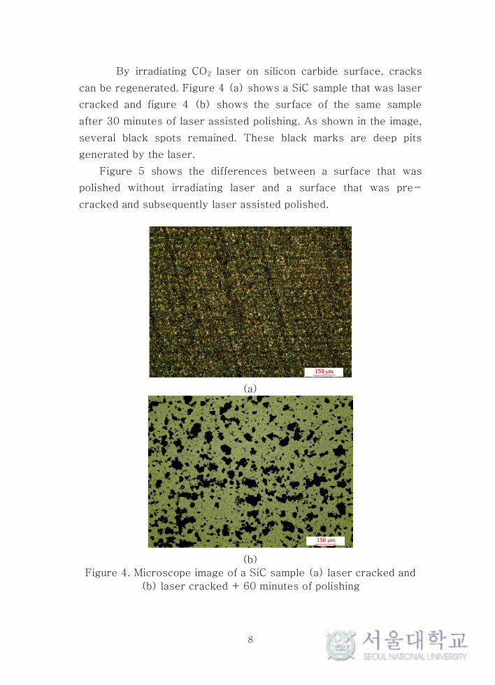
By irradiating CO2 laser on silicon carbide surface, cracks
can be regenerated. Figure 4 (a) shows a SiC sample that was laser
cracked and figure 4 (b) shows the surface of the same sample
after 30 minutes of laser assisted polishing. As shown in the image,
several black spots remained. These black marks are deep pits
generated by the laser.
Figure 5 shows the differences between a surface that was
polished without irradiating laser and a surface that was pre-
cracked and subsequently laser assisted polished.
(a)
(b)
Figure 4. Microscope image of a SiC sample (a) laser cracked and
(b) laser cracked + 60 minutes of polishing

9
Figure 5. Microscope image showing difference between laser
cracked surface and non-cracked
3.2. Experiment design
SiC samples with dimensions of 50 mm x 50 mm were used as the
target for this experiment. A 0.05 mm width raster tool path with
dimensions of 20 mm x 20 mm was used. Two different types of
SiC samples were prepared: SiC as-received and laser pre-
cracked sample. The tool size was 20 mm in diameter so the
deepest polished point lays on the middle of the sample.
As shown in figure 6, an area of 40 mm x 40 mm was laser
pre-cracked. Subsequently, a raster tool path of 0.05 mm width of
20 mm x 20 mm was used to perform the polishing process.

10
Figure 6. Diagram of MRR experiment’s tool path
Four different types of experiments were performed, as shown
in figure 7 to investigate the effect that each of them had on the
material removal rate (MRR) of Silicon Carbide (SiC) polishing.
Conventional polishing, laser assisted polishing (LAP), laser pre-
cracks + laser assisted polishing (CLAP), and re-cracking which
stands for the process in which laser pre-cracks are generated
every 30 minutes.
The laser cracking process does not only create cracks on SiC
surface but also evaporates some of the material. However, by
using a 25% duty cycle which equals to 74.43 W, the evaporated
material is negligible.

11
(a) Polishing
(b) LAP
(c) CLAP
(d)Re-cracking + LAP
Figure 7. (a) conventional polishing (P), (b) laser assisted polishing
(LAP), Pre-cracks + laser assisted polishing (CLAP), Re-cracking
process [21].

12
Table 2. Experiment parameters
Work piece Silicon carbide
Laser
Source CO2 (wavelength 10.6 μm)
Type Continuous wave
Power77.43 W (Laser crack)
111.1 W (Laser assisted polishing)
Feed rate 25 mm/s
Polishing
Tool diameter 20 mm
Force 18 N
Rotational speed 1,200 rpm
Slurry Diamond and ceria (~1 μm)
Pad Polyurethane
Feed rate 25 mm/s
3.3. Material Removal Measurement and Results
A surface profiler was used (Taylor Hobson, AMETEK inc.) to
measure the maximum polished depth for each of the experiment’s
samples. Surface profiler can only measure the surface on a straight
line, therefore it is not possible to know whether the surface was
uniformly polished or not. In order to get an average value for the
maximum polished depth, the surface was measured in 4 different
directions as shown in figure 8.

13
Figure 8. Diagram of the measurement of surface profile
Figure 9 shows the surface profiler data in 4 directions for
CLAP process after 35 minutes of machining. As it can be seen, the
profile is slightly different in some regions but overall it is very
similar in all directions.
Figure 9. Surface profile data for CLAP process for the 4 different
measured directions

14
Figure 10 shows that 19.4 um, 9.5 um and 8.9 um was the
maximum polished depth for cracked + laser assisted polishing,
laser (CLAP) assisted polishing (LAP) and conventional polishing
(P) respectively. Conventional polishing and laser assisted polishing
did not have much difference. However, laser cracks + laser
assisted polishing showed a high MRR in the area where laser was
irradiated during the polishing process.
Figure 10. Surface profiler data for the 4 different performed
experiments
The irradiated laser during laser assisted polishing seemed to
have a higher effect on the pre-cracked surface. In order, to study
the long term effect of pre-cracking and laser assisted polishing,
re-cracking was done every 30 minutes. The process outline is
described in figure 7 (d). First, the SiC as-received was cracked
by laser, afterwards, the sample was laser assisted polished and
after 30 minutes of polishing, the sample was cracked again by
laser and subsequently polished again and this process was
repeated. The maximum depth for this process was 26.5 um.

15
Figure 11. Surface profile data for re-cracking experiment over
prolonged period of time
The results from the performed experiment in order to test
the material removal rate over prolonged periods of time is shown
in figure 11.
The maximum polished depth and material removal rate (MRR)
for the 4 different experiments is shown in figure 12. For the
conventional polishing process, we can see that the material
removal stayed constant throughout the experiment. For the laser
assisted polishing process, there is an increase of material removal
at the early stage of the process but later on, the process’s material
removal rate becomes equal to the conventional process. In the
case of the pre-cracked + laser assisted polishing process, there is
a high increase of material removal rate on the early stage until a
point when all initial cracks are removed. Finally, on the re-
cracking process, the highest material removal rate occurs on the
early stage but thanks to the re-cracking, more cracks are
generated every time the sample is re-cracked and therefore
increasing material removal rate. However, as seen in the CLAP and
re-cracking process, the MRR decreases with time and becomes
almost equal to the conventional polishing’s MRR. The polishing

16
process has a characteristic of creating a high surface quality. This
leads to create a surface with high reflectivity. Some of the laser
that is irradiate on the surface is not absorbed and it is reflected.
This explains why the MRR decreases.
(a)
(b)

17
Figure 12. (a) Deepest polished point and (b) MRR of 4 different
experiments

18
Chapter 4. Macro/Micro Channels
4.1. Macro/Micro Channels Design
Polishing process has several limitations, one of them is that all the
area beneath the polishing pad will be machined and selective
machining cannot be done without changing the design of the
polishing tool. However, in this hybrid polishing process that was
developed, the material removal rate between the laser pre-
cracked regions and the non-pre-cracked regions is high enough
to possibly selectively create 3D forms on silicon carbide surface.
In order to test this hybrid process’s capability of creating
macro/micro grooves on silicon carbide, 2 different experiments
were conducted. An ‘ㄹ’ pattern with dimensions shown in figure 13
was laser cracked at 30% duty and subsequently laser assisted
polished, and a similar pattern with variable width was similarly
laser cracked and subsequently polished. A raster tool path of
0.05mm was used in both experiments.
The surface profile was measured using a surface profiler as
in previous experiments. Moreover, in order to map the 3D surface,
the surface profile was measured in 5 positions. The obtained data
was then interpolated to obtain a 3D grid to illustrate the generated
pattern.

19
Figure 13. Diagram of the machined patterns

20
The results are shown in figure 14. As it can be seen, the
pattern is not clearly seen, yet there is a higher material removal in
some of the areas in which laser was previously irradiated. Due to
the size of the polishing tool (radius=20mm), the material removal
on the edges of the tool is significantly higher than in areas closer
to the center. Therefore, before the tool reaches the lower part of
the pattern tool path, the surface has already become reflective and
the effect of laser assisted polishing is reduced on these areas.
(a)
(b)

21
Figure 14. (a) 3D surface and (b) surface profile data of generated
pattern

22
4.2. Tool Size Effect
Due to the size of the polishing pad, sharper patterns cannot be
made. Taking into consideration these results, the polishing PDMS
pad was modified. As shown in figure 15, the pad used for previous
experiment was 20 mm in radius and the modified version was 12
mm. There is a limitation of the polishing pad diameter since a 10
mm diameter hole is required for the laser to be able to reach the
sample’s surface
(a) (b)
Figure 15. (a) tool design for MRR experiment and failed pattern
machining, and (b) modified tool for patterning.
The same experiment was conducted to investigate the effects
of the modified tool size. Constant width and variable width channels
were machined with this tool.

23
(a)
Figure 16. (a) 3D surface and (b) surface profile data of generated
pattern with modified tool
(b)
4.3. Variable width channels
Previous experiments were conducted to validate the hypothesis
that with a high material removal difference between pre-cracked
and non-pre-cracked regions, specific patterns/shapes could be

24
generated. In order to study the size capabilities of this process, a
variable width pattern was designed. As shown in figure 13, the
width of the channels width was decreased from 2.0 mm to 0.2 mm.
The tool size and all other parameters including tool path and
polishing time were the same as of the constant width pattern
experiment.
(a)
(b)

25
Figure 17. (a) 3D surface and (b) surface profile data of generated
variable width pattern with modified tool
(a) (b)
Figure 18. Real image of (a) constant width channels and (b)
variable width channels
4.4. Tool Path Effect
The results in figure 16 and figure 17 showed that it is possible to
create grooves but laser cracking on small areas generates high
heat accumulation and due to the small time it gives for heat to
dissipate, it results on deep machined peaks. In order to evaluate
this hypothesis, we increased the raster tool path width from 50 μm
to 150 μm as shown in figure 19. This way, the laser effect on
these areas could be reduce, and therefore obtain a more uniform
depth along the pattern.
Surface profiler data shown in figure 20 shows that there
was a significant effect of the laser raster tool path width on the

26
depth of cut. In order to create grooves with uniform depth, a
parameter optimization has to be done to find the optimal raster tool
path’s width which leads to the deepest cracks with the less
material vaporization.
Figure 19. Modified raster tool path width

27
(a) 3D surface
Figure 20. (a) 3D surface and (b) surface profile data of generated
variable width pattern with modified tool and modified raster tool
path

28
Chapter 5. Spherical Mirror Fabrication
5.1. Mirror design and Fabrication
It has been proved that this hybrid process can create different
surface shapes depending on the tool path and how the sample is
pre-cracked. In order to fabricate a concave spherical mirror, the
pattern shown in figure 21 was pre-cracked. Concentric circles
were pre-cracked using the same raster tool path as previous
experiments (50 μm width). Each circle was cracked on top of the
previous one in order to create an increasing crack depth gradient.
This way, deeper cracks can be found in the center of the sample
and less deep cracks in the outer part. By doing this, when polishing
the sample, regardless the size and shape of the tool, the highest
material removal will be located at the center of the sample and a
concave spherical mirror can be fabricated.

29
Figure 21. Spherical mirror fabrication diagram
The dimensions of the spherical mirror were 127 μm at its
center, 50 mm of linear aperture and radius of curvature of 2200
mm. We chose these dimensions in order to match the commercial
Newtonian telescope mirror shown in figure 22. The dimensions and
parameters of this Newtonian telescope are shown in Table 3.

30
Figure 22. Commercial Newtonian telescope’s mirror and holder
Table 3. Mirror parameters
Parameter [unit] Value
Focal length 1100 mm
Linear aperture 150 mm
Primary mirror size 180 mm
On the contour of the concentric circles, we can see laser
marks. These laser marks are deep pits that cannot be remove
without further modification of the mirror shape. These mark are
the result of the dwell time when the laser tool change direction
after each raster path line. The dwell time is significantly high to
create deep pits on the contour of the circles.
Figure 23. Fabricated concave spherical mirror by hybrid process
The profiler data was fitted with the commercial mirror

31
profile data. The fitting had a R-square=0.9321 and the final
surface roughness was of 58 nm as shown in figure 24. Even though
the R-square value is relatively good enough, in some areas a flat
surface can be seen and this is due to the flat shaped tool.
Figure 24. Surface profile of commercial mirror and fabricated
mirror by hybrid process
5.2. Reflector of Newtonian Telescope
The Newtonian reflector is a classic mirror telescope design, and
Isaac Newton first built this telescope in 1668. Newton was further
developing an existing telescope design, one like the physicist
Zucchi had already constructed in 1616, which employed a mirror.
Newton’s idea was to install a flat reflecting mirror into the
telescope tube. Light would first enter the top of the telescope tube.
At the lower end, there is a primary mirror that is either spherical
or parabolic in configuration. This mirror reflects the light upwards.
To prevent the image from being focused in front of the tube
opening, there is a secondary mirror inside the top of the tube. This

32
is a plane mirror that deflects the light beam by 90°, thus directing it
out the side of the tube. The light enters the focuser here, into an
eyepiece that can be inserted for observation. Focusing takes place
by turning a focus wheel on the focuser so that the eyepiece is
moved towards or away from the telescope tube [22].
Figure 25. Newtonian telescope’s principle
A commercial Newtonian telescope was used to test the
fabricated concave spherical mirror. An ABS jig for the SiC mirror
was manufactured by fused deposition modeling (FDM) (Dimension
768 SST, Stratasys). Figure 26 shows the SiC mirror together with
the ABS jig
Figure 26. Fabricated SiC mirror and 3D printed jig
The fabricated SiC mirror was used to take the images
shown in figure 27. Images were taken at different stages of
fabrication to show the difference in magnification.

33
(a)
(b)
Figure 27. (a) image taken at early stage of polishing, and (b)
image of mirror with curvature of 2200 mm radius
As it can be seen in figure 27, there are some circular marks
in the pre-cracked shape. This laser marks are too deep to be
removed by polishing process without modifying the shape of the
mirror even further. Moreover, the shape of the mirror was not 100%
equal to the commercial mirror. In order to fabricated a more
accurate mirror, changes in experiment and tool design will have to
be done.

34
Chapter 6. Conclusion
A hybrid polishing method was studied and different types of
experiment were conducted in order to see the effects it has on the
polishing process of Silicon Carbide (SiC). 3 different studies were
done: material removal rate improvement, deep groves by hybrid
polishing process and concave mirror fabrication.
The results showed that there is an improvement of the
material removal rate by using this hybrid process over the
conventional polishing process. The initial improvement is higher
than 300% in comparison of conventional polishing, however, after
the material removal rate reaches its constant value, the
improvement is of 43% over conventional polishing.
Grooves were generated by cracking and subsequently laser
assisted polishing on the cracked path. Deep groves of different
sizes were generated. However, there are some limitations
including the maximum width and the depth uniformity. These
grooves could be generated over the whole surface of the sample
and therefore improve its tribological properties.
Finally, a SiC mirror was fabricated in a shorter period of
time than what conventional polishing process could have done.
However, controlling the curvature of the mirror is not an easy task
due to the flat shaped tool and lack of real time monitoring of the
curvature.
Moreover, due to the flat shape, when the depth at the
middle becomes significantly large, the tool mostly removes
material at the sides and not at the middle, leading to a flat shape at
this point.
More study has to be done related to the effect of surface
reflectance and material removal rate. Also, modifying the raster
tool path’s width could significantly improve the non-uniform depth
of the generated groove.

35
Bibliography
1. Johnson, J. S., Grobsky, K. D., & Bray, D. (2002, September). Rapid fabrication of lightweight silicon-carbide mirrors. In Optomechanical Design and Engineering 2002 (Vol. 4771, pp. 243-253).
2. Sun, S., Brandt, M. and Dargusch, M.S., 2010. Thermally enhanced machining of hard-to-machine materials—a review. International Journal of Machine Tools and Manufacture, 50(8), pp.663-680.
3. Suzuki, H., Kodera, S., Nakasuji, T., Ohta, T. and Syoji, K., 1998. Precision grinding of aspherical CVD-SiC molding die. International Journal of the Japan Society for Precision Engineering, 32(1), pp.25-30.
4. Evans, C.J., Paul, E., Dornfeld, D., Lucca, D.A., Byrne, G., Tricard, M., Klocke, F., Dambon, O. and Mullany, B.A., 2003. Material removal mechanisms in lapping and polishing. CIRP annals, 52(2), pp.611-633.
5. Kim, D.H. and Lee, C.M., 2016. A study on the laser-assisted ball-end milling of difficult-to-cut materials using a new back-and-forth preheating method. The International Journal of Advanced Manufacturing Technology, 85(5-8), pp.1825-1834.
6. Klocke, F. and Zunke, R., 2009. Removal mechanisms in polishing of silicon based advanced ceramics. CIRP annals, 58(1), pp.491-494.
7. Wegener, K., Bleicher, F., Krajnik, P., Hoffmeister, H.W. and Brecher, C., 2017. Recent developments in grinding machines. CIRP Annals, 66(2), pp.779-802.
8. Chen, B., Li, S., Deng, Z., Guo, B. and Zhao, Q., 2017. Grinding marks on ultra-precision grinding spherical and aspheric surfaces. International Journal of Precision Engineering and Manufacturing-Green Technology, 4(4), pp.419-429
9. Xing, Y., Deng, J., Zhang, K., Zhang, G. and Gao, H., 2014. Effect of femtosecond laser pretreatment on wear

36
resistance of Al2O3/TiC ceramic tools in dry cutting. International Journal of Refractory Metals and Hard Materials, 43, pp.291-301.
10. Zum Gahr, K.H., 1989. Sliding wear of ceramic-ceramic, ceramic-steel and steel-steel pairs in lubricated and unlubricated contact. Wear, 133(1), pp.1-22.
11. Tsumori, F., Hunt, S., Kudo, K., Osada, T. and Miura, H., 2016. Wavy Micro Channels in Micropatterned Ceramic Sheet Formed by Combined Process of Laser Beam Machining and Imprinting. Journal of the Japan Society of Powder and Powder Metallurgy, 63(7), pp.511-518.
12. Dandekar, C.R., Shin, Y.C. and Barnes, J., 2010. Machinability improvement of titanium alloy (Ti–6Al–4V) via LAM and hybrid machining. International Journal of Machine Tools and Manufacture, 50(2), pp.174-182.
13. Lauwers, B., Klocke, F., Klink, A., Tekkaya, A.E., Neugebauer, R. and Mcintosh, D., 2014. Hybrid processes in manufacturing. CIRP Annals, 63(2), pp.561-583.
14. Chu, W.S., Kim, M.S., Jang, K.H., Song, J.H., Rodrigue, H., Chun, D.M., Cho, Y.T., Ko, S.H., Cho, K.J., Cha, S.W. and Min, S., 2016. From design for manufacturing (DFM) to manufacturing for design (MFD) via hybrid manufacturing and smart factory: A review and perspective of paradigm shift. International Journal of Precision Engineering and Manufacturing-Green Technology, 3(2), pp.209-222.
15. Chu, W.S., Kim, C.S., Lee, H.T., Choi, J.O., Park, J.I., Song, J.H., Jang, K.H. and Ahn, S.H., 2014. Hybrid manufacturing in micro/nano scale: a review. International journal of precision engineering and manufacturing-green technology, 1(1), pp.75-92.
16. Jeon, Y., Park, H.W. and Lee, C.M., 2013. Current research trends in external energy assisted machining. International Journal of Precision Engineering and Manufacturing, 14(2), pp.337-342.
17. Kurniawan, R., Ali, S., Park, K.M., Li, C.P. and Ko, T.J., 2019. Development of a Three-Dimensional Ultrasonic

37
Elliptical Vibration Transducer (3D-UEVT) Based on Sandwiched Piezoelectric Actuator for Micro-grooving. International Journal of Precision Engineering and Manufacturing, pp.1-12.
18. Liang, Y., Chen, Y., Chen, B., Fan, B., Yan, C. and Fu, Y., 2019. Feasibility of Ultrasonic Vibration Assisted Grinding for Carbon Fiber Reinforced Polymer with Monolayer Brazed Grinding Tools. International Journal of Precision Engineering and Manufacturing, pp.1-12.
19. Cha, N.H. and Lee, C.M., 2015. A study on machining characteristics of silicon nitride with spline members in laser-assisted turn-mill. International Journal of Precision Engineering and Manufacturing, 16(13), pp.2691-2697.
20. Lee, C.M., Kim, D.H., Baek, J.T. and Kim, E.J., 2016. Laser assisted milling device: A review. International Journal of Precision Engineering and Manufacturing-Green Technology, 3(2), pp.199-208.
21. 김민철. (2019). 실리콘 카바이드 가공을 위한 레이저-폴리싱 융복합 공정.
22. VandeWettering, Mark T. (2001). "Telescope Basics".

38
국문 초록
실리콘 카바이드에 대한 CO2 레이저 연마의
효과
파블로
서울대학교 공과대학원
기계항공공학부 기계공학전공
실리콘 카바이드 (SiC)는 일반적으로 사용되는 다른 유리 및 금속보다
많은 장점을 제공하기 때문에 오랫동안 고성능 광학 응용 분야에서
우수한 재료로 인정 받고 있다. SiC의 우수한 특성 중 일부는 매우 높은
고유 강성 (E / ρ), 높은 열 전도성 및 뛰어난 치수 안정성을 포함한다.
실리콘 카바이드에 대한 CO2 레이저 연마와 레이저의 공구 경로의
효과가 조사하였다. 이 하이브리드 과정에는 먼저 원하는 패턴에 레이저
크랙을 냈다. 이어서, 레이저 보조 연마가 동일한 공구 경로에서
수행된다. 표면은 레이저 유도 크랙이 있는 영역과 크랙이 없는
영역에서 물질 제거에 있어 뚜렷한 차이를 보였다. 이러한 물질 제거의
높은 차이는 매크로 및 미세 패턴을 가공하기 위해서 사용되었다. 폭은
2 mm에서 200 μm까지, 그리고 깊이는 5 μm에서 20 μm까지 홈이
성공적으로 생성되었다. 또한, 이 하이브리드 과정은 Newtonian
망원경의 일부로 사용되는 구형 오목 거울을 가공하기 위해 사용되었다.
주요어: 연마, 하이브리드, 재료 제거율 (MRR), 패터닝
학번: 2017-26782