disco swing check valves wb 26, wb 26a, wb 24s for … · disco swing check valves wb 26, wb 26a,...
TRANSCRIPT
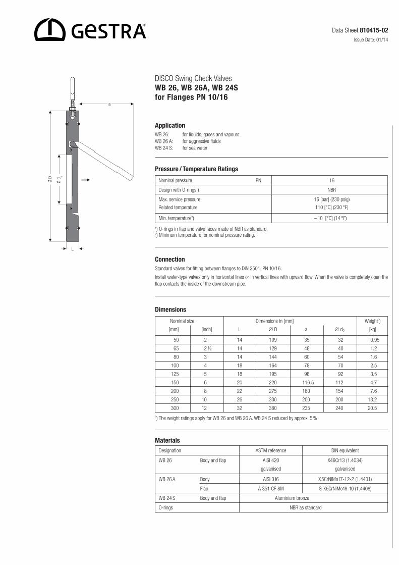
DISCO Swing Check Valves WB 26, WB 26A, WB 24Sfor Flanges PN 10/16
Nominal pressure PN 16
Design with O-rings1) NBR
Max. service pressure 16 [bar] (230 psig)
Related temperature 110 [°C] (230 °F)
Min. temperature2) – 10 [°C] (14 °F)1
Pressure / Temperature Ratings
ApplicationWB 26: for liquids, gases and vapoursWB 26 A: for aggressive fluidsWB 24 S: for sea water
1) O-rings in flap and valve faces made of NBR as standard.2) Minimum temperature for nominal pressure rating.
ConnectionStandard valves for fitting between flanges to DIN 2501, PN 10/16.
Install wafer-type valves only in horizontal lines or in vertical lines with upward flow. When the valve is completely open the flap contacts the inside of the downstream pipe.
Nominal size Dimensions in [mm] Weight3)
[mm] [inch] L ∅ D a ∅ dO [kg]
50 12 14 109 135.5, 132 10.95
65 12 ½ 14 129 148.5, 140 11.21
80 13 14 144 160.5, 154 11.61
100 14 18 164 178.5, 170 12.51
125 15 18 195 198.5, 192 13.51
150 16 20 220 116.5 112 14.71
200 18 22 275 160.5 154 17.61
250 10 26 330 200.5 200 13.21
300 12 32 380 235.5 240 20.51
Dimensions
3) The weight ratings apply for WB 26 and WB 26 A. WB 24 S reduced by approx. 5 %
Designation ASTM reference DIN equivalent
WB 26 Body and flap AISI 420 X46Cr13 (1.4034)
galvanised galvanised
WB 26 A Body AISI 316 X5CrNiMo17-12-2 (1.4401)
Flap A 351 CF 8M G-X6CrNiMo18-10 (1.4408)
WB 24 S Body and flap Aluminium bronze
O-rings NBR as standard
Materials
Data Sheet 810415-02Issue Date: 01/14
Ø D
Ø d o
a
L
810415-02/01-2014cm (803992-03) · GESTRA AG · Bremen · Printed in Germany
Supply in accordance with our general terms of business.
DISCO Swing Check Valves WB 26, WB 26A, WB 24Sfor Flanges PN 10/16
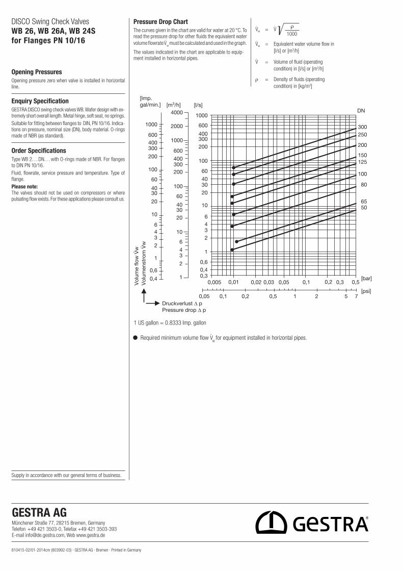
Opening PressuresOpening pressure zero when valve is in stalled in horizontal line.
Enquiry SpecificationGESTRA DISCO swing check valves WB. Wafer design with ex-tremely short overall length. Metal hinge, soft seat, no springs.Suitable for fitting between flanges to DIN, PN 10/16. Indica-tions on pressure, nominal size (DN), body material. O-rings made of NBR (as standard).
Order SpecificationsType WB 2. . . DN. . . with O-rings made of NBR. For flanges to DIN PN 10/16.Fluid, flowrate, service pressure and tem perature. Type of flange.Please note:The valves should not be used on com pressors or where pulsating flow exists. For these applications please consult us.
Pressure Drop ChartThe curves given in the chart are valid for water at 20 °C. To read the pressure drop for other fluids the equivalent water volume flowrate V̇
w must be calculated and used in the graph.
The values indicated in the chart are applicable to equip-ment installed in horizontal pipes.
V̇w = V̇ ————
1000
V̇w = Equivalent water volume flow in [l/s] or [m3/h]
V̇ = Volume of fluid (operating condition) in [l/s] or [m3/h]
r = Density of fluids (operating condition) in [kg/m3]
1 US gallon = 0.8333 Imp. gallon
ρ
5065
80
100
125150
200
250300
DN
0,01 0,02 0,03 0,30,050,005 0,1 0,2 0,5[bar]
[psi]10,50,20,10,05 2 5 7
100
200300400
600
1000
60
403020
10
6432
1
0,60,40,3
[l/s][m3/h]
100
200300400
600
1000
2000
4000
10
203040
60
1
2
34
6
10
20
3040
60
100
200
300400600
1000
6432
1
0,6
0,4
[Imp.gal/min.]
Druckverlust ∆ p
Vol
umen
stro
m V
w
Pressure drop ∆ p
Vol
ume
flow
Vw
Required minimum volume flow V·W
for equipment installed in horizontal pipes.
GESTRA AG Münchener Straße 77, 28215 Bremen, GermanyTelefon +49 421 3503-0, Telefax +49 421 3503-393E-mail [email protected], Web www.gestra.de