discrete wires - nasa books/links...discrete wires (cont.) through-possible. see section 6.01...
TRANSCRIPT
THROUGH-HOLE SOLDERING DISCRETE WIRES (cont.)
PREFERRED THROUGH-HOLE TERMINATION
FINAL ASSEMBLY
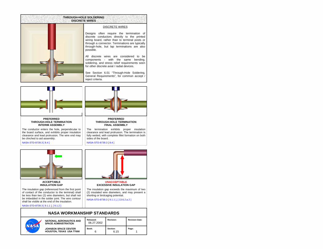
The termination exhibits proper insulation clearance and lead protrusion. The termination is fully wetted, with complete fillet formation on both sides of the board.
NASA-STD-8739.3 [ 8.4 ]
PREFERRED THROUGH-HOLE TERMINATION
INTERIM ASSEMBLY
The conductor enters the hole, perpendicular to the board surface, and exhibits proper insulation clearance and lead protrusion. The wire end may be clinched to aid assembly.
NASA-STD-8739.3 [ 8.4 ]
UNACCEPTABLE EXCESSIVE INSULATION GAP
The insulation gap exceeds the maximum of two (2) insulated wire diameters, and may present a shorting or birdcaging potential.
NASA-STD-8739.3 [ 9.1.1 ], [ 13.6.2.a.2 ]
Page:
1
Revision Date:
Section:
6.15
Revision:
Book:
6
Released:
06.27.2002
ACCEPTABLE INSULATION GAP
The insulation gap (referenced from the first point of contact of the conductor to the terminal) shall be less than two (2) wire diameters, but shall not be imbedded in the solder joint. The wire contour shall be visible at the end of the insulation.
NASA-STD-8739.3 [ 9.1.1 ], [ 9.1.2 ]
NASA WORKMANSHIP STANDARDS
DISCRETE WIRES Designs often require the termination of discrete conductors directly to the printed wiring board, rather than to terminal posts or through a connector. Terminations are typically through-hole, but lap terminations are also possible. All discrete wires are considered to be components - with the same bending, soldering, and stress relief requirements seen for other discrete axial / radial devices. See Section 6.01 “Through-Hole Soldering, General Requirements”, for common accept / reject criteria.
THROUGH-HOLE SOLDERING DISCRETE WIRES
Page:
3
Revision Date:
Section:
6.16
Revision:
Book:
6
Released:
06.27.2002
NASA WORKMANSHIP STANDARDS
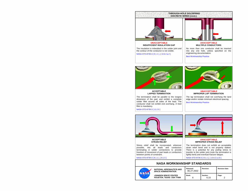
UNACCEPTABLE INSUFFICIENT INSULATION GAP
The insulation is imbedded in the solder joint and the contour of the conductor is not visible.
NASA-STD-8739.3 [ 9.1.1 ], [ 13.6.2.a.2 ]
UNACCEPTABLE MULTIPLE CONDUCTORS
No more than one conductor shall be inserted into any one hole, unless specified on the engineering documentation.
Best Workmanship Practice
ACCEPTABLE LAPPED TERMINATION
The termination shall be parallel to the longest dimension of the pad, and exhibit a complete solder fillet around all sides of the lead. The conductor shall not exhibit end overhang. A heel fillet is mandatory.
NASA-STD-8739.3 [ 11.2.5 ]
UNACCEPTABLE IMPROPER LAP TERMINATION
The lap termination shall not overhang the land edge and/or violate minimum electrical spacing.
Best Workmanship Practice
ACCEPTABLE STRAIN RELIEF
Stress relief shall be incorporated, wherever possible, into all leads and conductors terminating in solder connections to provide freedom of movement of part leads or conductors between points of constraint.
NASA-STD-8739.3 [ 8.1.1 ], [ 8.1.5 ]
UNACCEPTABLE IMPROPER STRAIN RELIEF
The termination does not exhibit an acceptable strain relief bend and is not properly staked. There is a potential for any pulling stress to transfer to the solder joint (note the termination is lightly bent) and eventual fracture fatigue.
NASA-STD-8739.3 [ 8.1.1 ], [ 13.6.2.a.10 ]
Revision:
Page:
4
Revision Date:
Book:
6
Released:
06.27.2002
Section:
6.16
NASA WORKMANSHIP STANDARDS
THROUGH-HOLE SOLDERING DISCRETE WIRES (cont.)
Section:
6.15
Revision:
Page:
2
Revision Date:
Book:
6
Released:
06.27.2002
NASA WORKMANSHIP STANDARDS
THROUGH-HOLE SOLDERING DISCRETE WIRES (cont.)