discussion on fugitive emissions standards · 2018-04-04 · api-624 • this api standard...
TRANSCRIPT
Discussion on Fugitive Emissions Standards
Rich Davis
Business Development Manager
Flexitallic LP

Emissions Standards
• API 622 Type Testing of Process Valve Packing for Fugitive Emissions (under revision)
• API 624
• API 641
2
Why Do We Do Fugitive Emissions Standards?
3

Rich Davis
• A little history:
• Since 1990, I’ve been involved in the creation and implementation of test standards covering fugitive emissions.
• These included:– Chairman ISA SP0093 Fugitive Emissions Valve Test
– Member API 622 & Revision 1
– Member ISO 15848-1 & 2
– Co Chair API 624
4
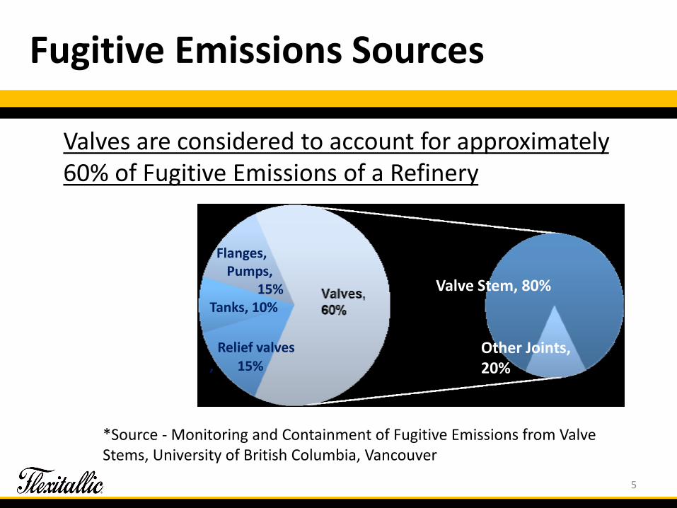
Fugitive Emissions Sources
Valve Stem, 80%
Other Joints, 20%
Flanges, Pumps,
15%Tanks, 10%
Relief valves, 15%
Valves are considered to account for approximately 60% of Fugitive Emissions of a Refinery
*Source ‐ Monitoring and Containment of Fugitive Emissions from Valve Stems, University of British Columbia, Vancouver
5

History
• Testing started with the Petroleum Environmental Research Forum – 93-20
• About 1993
6
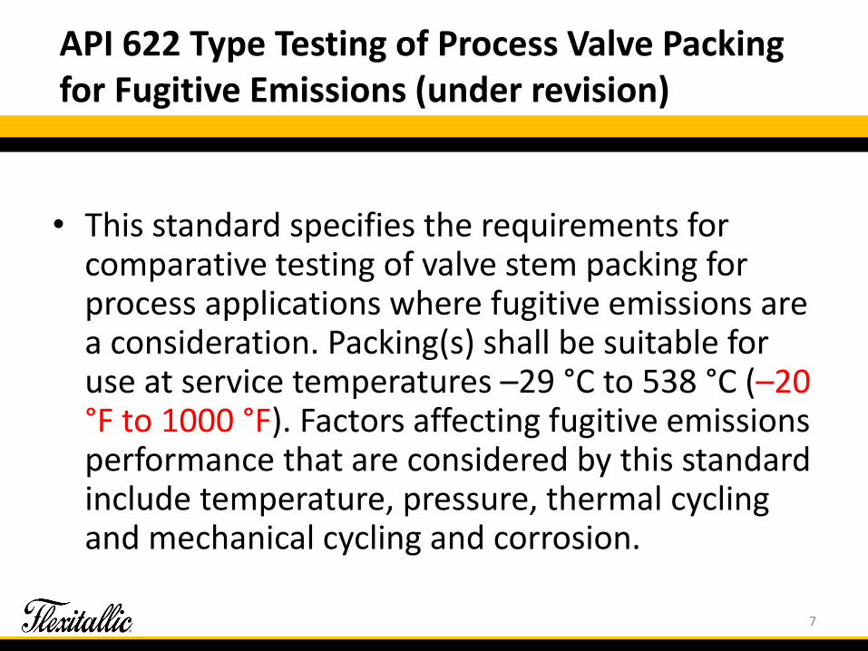
API 622 Type Testing of Process Valve Packing for Fugitive Emissions (under revision)
• This standard specifies the requirements for comparative testing of valve stem packing for process applications where fugitive emissions are a consideration. Packing(s) shall be suitable for use at service temperatures –29 °C to 538 °C (–20 °F to 1000 °F). Factors affecting fugitive emissions performance that are considered by this standard include temperature, pressure, thermal cycling and mechanical cycling and corrosion.
7

Graphite Oxidation
• –20 °F to 1000 °F, exceeds the capabilities of graphite, when exposed to oxygen.
• The upper temperature can be an issue.
• This is why we require an oxidation analysis in API 622.
• Flexitallic is currently working on a study of graphite and oxidation. We are working to assess oxidation inhibitors and how they work.
8

API-622
Mechanical cycles = 1510
• The test fixture shall be equipped with an actuator capable of stroking the test stem to simulate the mechanical cycle of a valve as follows:
– Rotating stem:
– Rate: 10° to 15° per second
– Rotation: 90° ±5°
• Test fixture packing gland dimensions and tolerances are specified.
• The test fixture is arranged to follow the PERF testing. It relays the information obtained in that testing.
9
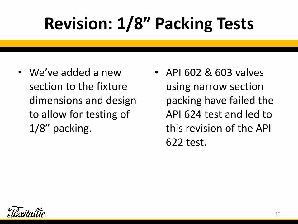
Revision: 1/8” Packing Tests
• We’ve added a new section to the fixture dimensions and design to allow for testing of 1/8” packing.
• API 602 & 603 valves using narrow section packing have failed the API 624 test and led to this revision of the API 622 test.
10

Twisted / Rolled Graphite Packing
1/8” Cross Section Packing Possible construction
Twisted / Rolled packingdoesn’t offer the same levelof sealing as the cross braidpacking.
11
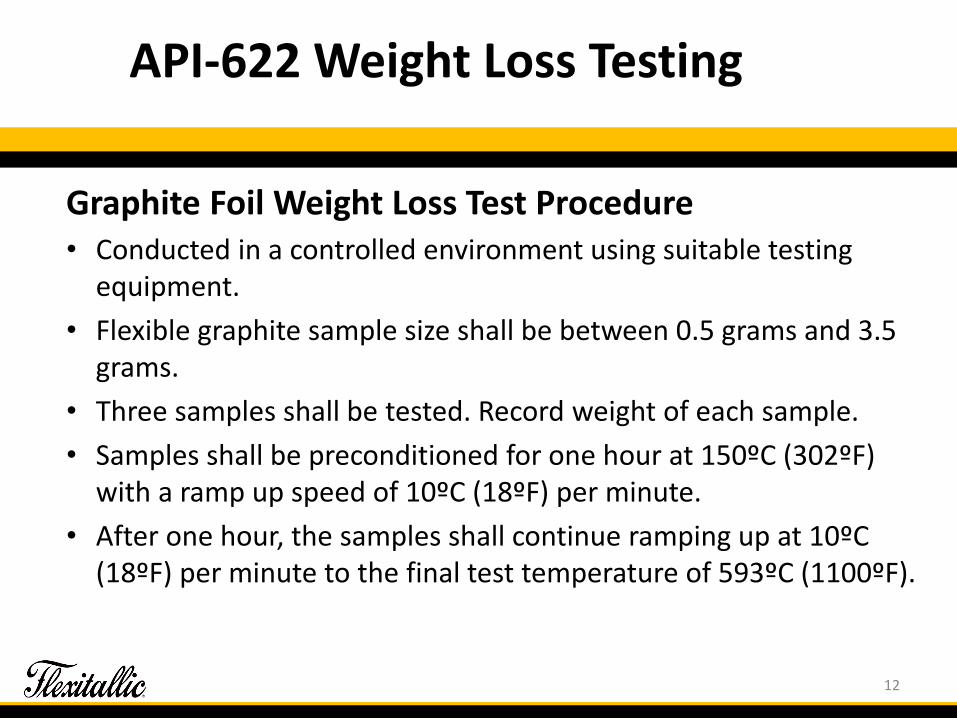
API-622 Weight Loss Testing
Graphite Foil Weight Loss Test Procedure• Conducted in a controlled environment using suitable testing
equipment.
• Flexible graphite sample size shall be between 0.5 grams and 3.5 grams.
• Three samples shall be tested. Record weight of each sample.
• Samples shall be preconditioned for one hour at 150ºC (302ºF) with a ramp up speed of 10ºC (18ºF) per minute.
• After one hour, the samples shall continue ramping up at 10ºC (18ºF) per minute to the final test temperature of 593ºC (1100ºF).
12

API-622 Weight Loss Testing
• This test temperature shall be held for 24 hours and then cooled.
• Weigh samples after cooling and record weight. TGA testers can weigh samples without being removed from the heat source which is acceptable.
• Determine the percent weight loss of each sample and record.
• Average the results and a weight loss greater than 15% is not acceptable.
• Note: This test method also follows an established testing standard, FSA-G-604-07, issued by the Fluid Sealing Association.
13

Test Procedure
• Test Fluid: The test fluid used shall be dry methane gas, 97% minimum purity, subjected to a temperature range from ambient to 260ºC (500ºF) and pressures from 0 to 4,137 kPag (0 to 600 psig).
14

Revision of Leak Detection Device Specifications
• The original standard laid out specific details of the leak detection equipment that could only be fulfilled by a TVA-1000 leak detector.
• The revision of this section will permit the use of a wider range of newer leak detection devices.
• An Example: Phoenix PHX21
15
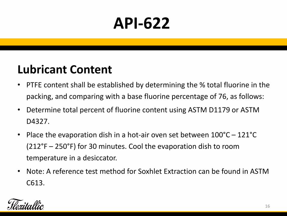
API-622
Lubricant Content• PTFE content shall be established by determining the % total fluorine in the
packing, and comparing with a base fluorine percentage of 76, as follows:
• Determine total percent of fluorine content using ASTM D1179 or ASTM
D4327.
• Place the evaporation dish in a hot-air oven set between 100°C – 121°C
(212°F – 250°F) for 30 minutes. Cool the evaporation dish to room
temperature in a desiccator.
• Note: A reference test method for Soxhlet Extraction can be found in ASTM
C613.
16

API 622 Corrosion Test
Corrosion Test Overview
• The corrosion test provides methods for evaluation of “cold” and “hot” corrosion caused by the packing. It also provides a means for evaluating the effect of inhibitor systems and valve stem metallurgy combinations with respect to corrosion rate and weight loss.
17
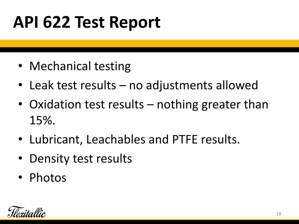
API 622 Test Report
• Mechanical testing
• Leak test results – no adjustments allowed
• Oxidation test results – nothing greater than 15%.
• Lubricant, Leachables and PTFE results.
• Density test results
• Photos
18

API 624 Type Testing of Rising Stem Valves Equipped with Graphite Packing for Fugitive Emissions
19

API-624
• This API standard specifies the requirements and acceptance criteria (100 ppmv) for fugitive emission type testing of rising and rising-rotating stem valves equipped with packing previously tested in accordance with API Standard 622.
• Packing shall be suitable for use at service temperatures –29°C to 538°C (–20°F to 1000°F).
• The type testing requirements contained herein are based upon elements of EPA Method 21.
• Valves larger than NPS 24 or greater than class 1500 are outside the scope of this standard.
20
API-624 Valve Selection & Pre-test
• The test valve shall be completely assembled and ready for testing. Test valve shall be randomly selected from manufacturer or distributor stock where such stock is available.
• For valves not in stock, the manufacturer shall certify that the test valve was not modified in any way to meet type test requirements and is a typical representation of the manufacturer’s stock product.
• Valve selection shall be approved by the purchaser.
21
Position - Safety - Gas
• The stem orientation for a test valve shall be vertical
– This has created some problems with some lubricants.
• As a safety precaution, the air in the valve cavity shall be purged with an inert gas prior to starting the testing.
• The test medium used shall be either methane gas,
97% minimum purity.
22

API-624 Type Testing
– Valves are subjected to a total of 310 mechanical cycles and 3 thermal cycles.
– Mechanical cycling shall begin with the valve at ambient temperature.
– An optional low temperature test at -29°C (-20°F) may be performed if requested by the purchaser.
– The elevated test temperature shall be 260°C ± 2 percent (500°F ± 5 percent).
– The test pressure shall be the lower of 600 psig or the maximum allowable pressure at 500 °F per ASME B16.34 for the applicable material group and shall be held constant throughout the test.
23

API 624
24

API 624
– Leak Measurement
• Packing leakage measurements around the full circumference of the stem OD and packing OD and the highest reading shall be recorded. Static and dynamic stem leakage measurements shall be taken.
– This is typically done using aluminum foil surrounding the stem.
• Leak measurements shall be sniffed using a detection probe. (This is often done using an aluminum foil)
• Packing adjustment during type testing is not permitted.
25

API 624 Valves Qualified
All valves of the same basic design as the test valve may be deemed to have been type tested, subject to additional limitations:
26
API 624 Valves Qualified
• Any change in valve sealing system design, packing material, packing manufacturer, or packing
type/model requires a requalification.
• If the location of the valve manufacturing facilities is different than what is listed on the API 624 certificate, the purchaser may request re-qualification.
27

API 641 Type Testing of Quarter-turn Valves for Fugitive Emissions
28

API 641 Scope
• This standard specifies the requirements and acceptance criteria for fugitive emission type testing of quarter-turn valves. The type testing requirements contained herein are based upon elements of EPA Method 21.
• Valves larger than NPS 24and valves greater thanASMEB16.34 class 1500 are outside the scope of this standard. Valves with a pressure rating at ambient temperature less than 6.89 barg (100 psig) are outside the scope of this standard. Repacking or resealing of valves is outside the scope of this standard.
29
Valve Selection & Test Preparation
• The test valve shall be fully assembled, tested to applicable industry standards, and ready for fugitive emissions testing. The test valve shall be randomly selected from manufacturer or distributor stock, where such stock is available. For valves not in stock, the manufacturer shall certify that the test valve was not modified in any way to meet type test requirements and is a typical representation of the manufacturer’s stock product.
30

Safety Considerations for Type Testing
• The test medium used shall be methane 97% minimum purity.
• The valve may be de-pressured between thermal cycles.
• All testing shall be in accordance with local and national codes and regulations.
• Purge the partially open valve with methane gas to eliminate air in the valve cavity prior to starting the testing.
31

Type Testing
Currently a total of 1510 mechanicalcycles and 3 thermal cycles
32

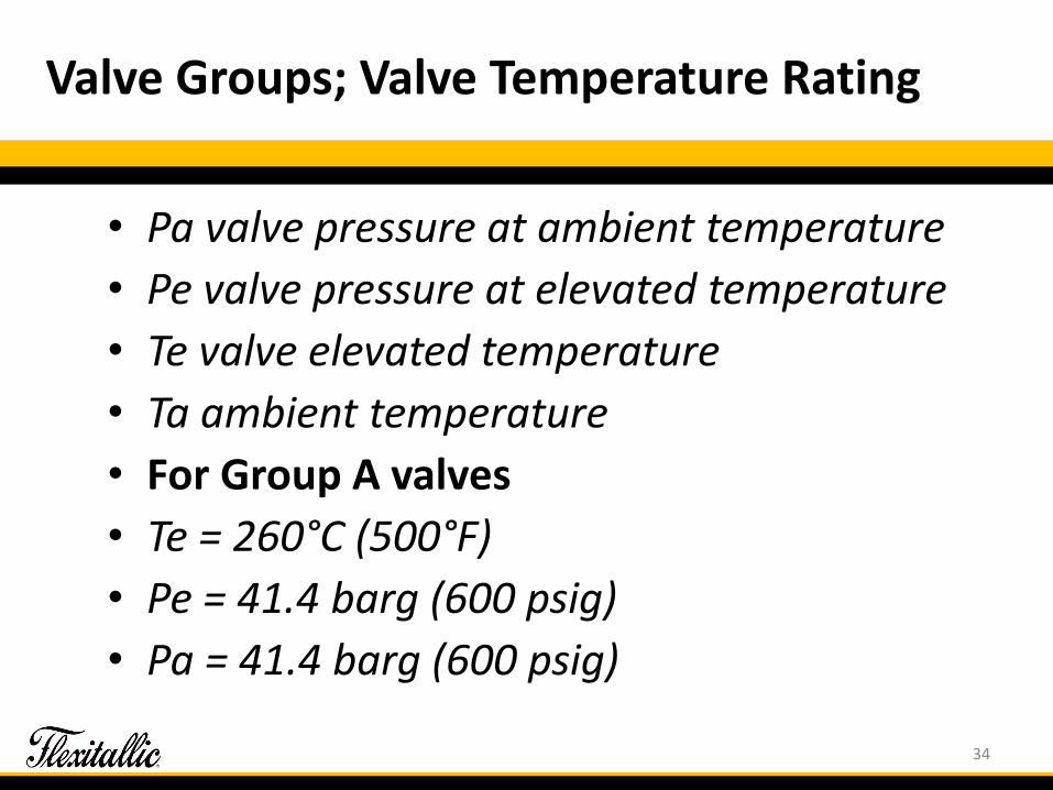
Valve Groups; Valve Temperature Rating
33
Valve Groups; Valve Temperature Rating
• Pa valve pressure at ambient temperature
• Pe valve pressure at elevated temperature
• Te valve elevated temperature
• Ta ambient temperature
• For Group A valves
• Te = 260°C (500°F)
• Pe = 41.4 barg (600 psig)
• Pa = 41.4 barg (600 psig)
34

Valve Groups; Valve Temperature Rating
• For Group B valves
• Te = 260°C (500°F)
• Pe = Valve Pressure rating at 260°C (500°F)
• Pa = Valve Pressure rating at ambient temperature or 41.4 barg (600 psig), whichever is less
35
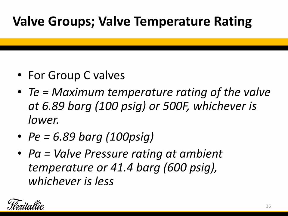
Valve Groups; Valve Temperature Rating
• For Group C valves
• Te = Maximum temperature rating of the valve at 6.89 barg (100 psig) or 500F, whichever is lower.
• Pe = 6.89 barg (100psig)
• Pa = Valve Pressure rating at ambient temperature or 41.4 barg (600 psig), whichever is less
36

Valve Groups; Valve Temperature Rating < 260°C (500°F)
37

Valve Groups; Valve Temperature Rating < 260°C (500°F)
• For Group D valves
• Te = Maximum temperature rating of valve
• Pe = 41.4 barg (600 psig)
• Pa = 41.4 barg (600 psig)
38

Valve Groups; Valve Temperature Rating < 260°C (500°F)
• For Group E valves
• Te = Maximum temperature rating of valve
• Pe = Valve pressure rating at maximum temperature rating of valve
• Pa = Valve pressure rating at ambient temperature or 41.4 barg (600 psig), whichever is less
39
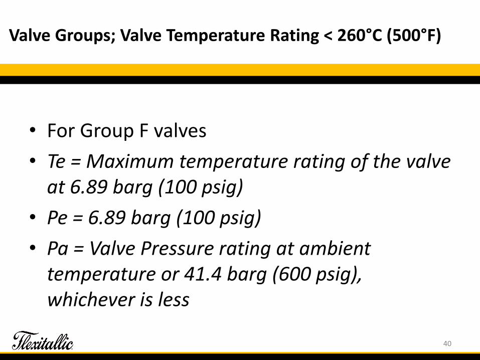
Valve Groups; Valve Temperature Rating < 260°C (500°F)
• For Group F valves
• Te = Maximum temperature rating of the valve at 6.89 barg (100 psig)
• Pe = 6.89 barg (100 psig)
• Pa = Valve Pressure rating at ambient temperature or 41.4 barg (600 psig), whichever is less
40

Valve Groups; Valve Temperature Rating < 260°C (500°F)
• The elevated test temperature, test pressure while at the elevated test temperature, and test pressure while at ambient temperature shall be as follows for any valve tested per this standard.
• The elevated test temperature shall be equal to the value established for variable Te per section 8.7 or 8.8
• The test pressure while at the elevated test temperature shall be the value established for variable Pe per section 8.7 or 8.8.
• The test pressure while at ambient temperature shall be the value established for variable Pa per section 8.7 or 8.8.
41

Actuation
• The test valve may be equipped with a method of actuation capable of mechanically cycling the valve.
• For torque-seated valves with offset stems, the closing torque shall be set to the manufacturer’s published torque used for seat closure at the corresponding maximum test pressure.
• Running torque values shall be recorded at approximately mid-stroke on the first and last mechanical cycle of testing.
42
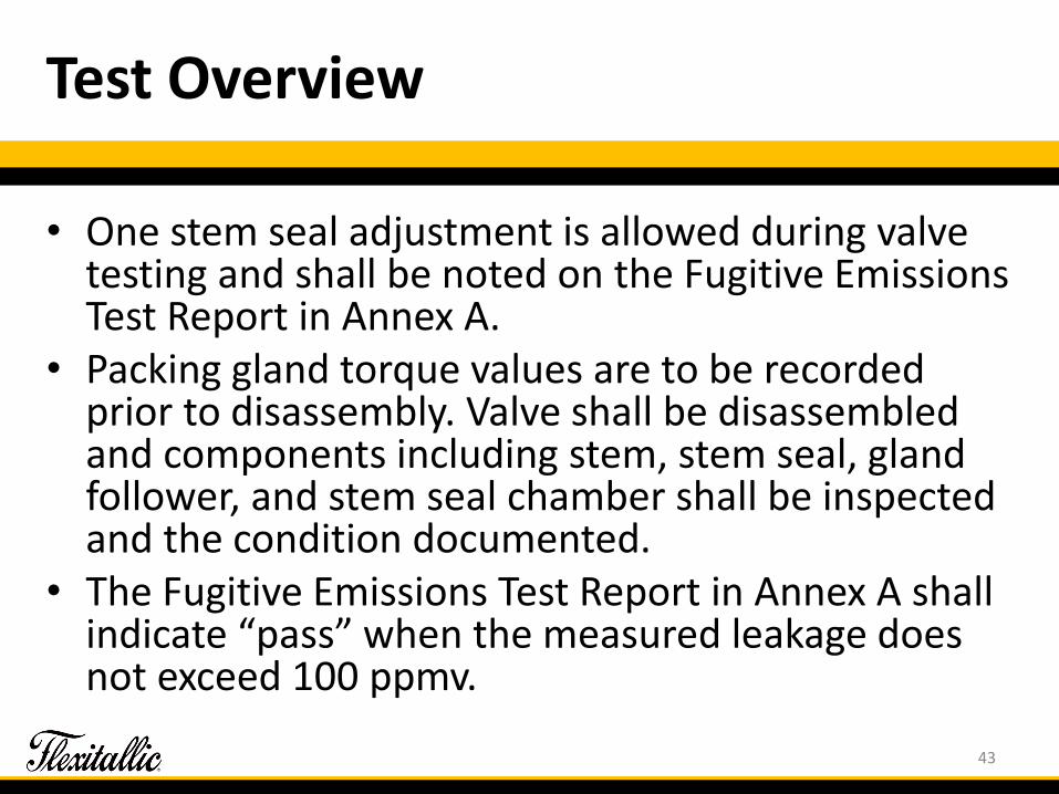
Test Overview
• One stem seal adjustment is allowed during valve testing and shall be noted on the Fugitive Emissions Test Report in Annex A.
• Packing gland torque values are to be recorded prior to disassembly. Valve shall be disassembled and components including stem, stem seal, gland follower, and stem seal chamber shall be inspected and the condition documented.
• The Fugitive Emissions Test Report in Annex A shall indicate “pass” when the measured leakage does not exceed 100 ppmv.
43
Leak Test Equipment and Calibration
• Similar to the new API 622
• The test equipment shall be inspected prior to each use to ensure against fouling of the detector probe.
44

Valves Qualified
• Valves of the same quarter-turn design as the test valve may be deemed to be a qualified, subject to the following additional limitations:
• The value for Te, as determined by section 8.7 or 8.8, is not greater than the value for Te of the test valve.
• The value for Pe, as determined by section 8.7 or 8.8, is not greater than the value for Pe of the test valve.
• The value for Pa, as determined by section 8.7 or 8.8, is not greater than the value for Pa of the test valve.
45

Valves Qualified
• Stem diameter is between one-half to two times the test valve; • The stem seal is of the same material, design, sealing stress,
shape and construction, independent of the seal size; • The dimensions of the overall seal set height is between 75% and
125% of the test valve; • The type of motion, the type of obturator, the type of obturator
support, the type of offset, and the type of stem support is identical;
• Tolerance classes (grades) and surface finish specifications of all valve components which affect sealing performance are identical.
• Any change in valve sealing system design including, but not limited to, stem seal material, stem seal manufacturer, or stem seal model requires a requalification.
46

THANK YOU
47