dispersion-managed soliton in fiber links with in-line filtering presented in the basis of chirped...
TRANSCRIPT

S. K. Turitsyn and E. G. Shapiro Vol. 16, No. 9 /September 1999 /J. Opt. Soc. Am. B 1321
Dispersion-managed soliton in fiber links within-line filtering presented in the
basis of chirped Gauss–Hermite functions
Sergei K. Turitsyn
Photonics Research Group, School of Engineering and Applied Science, Aston University, Birmingham B4 7ET, UK
Elena G. Shapiro
Institute of Automation and Electrometry, 630090, Novosibirsk, Russia
Received November 9, 1999
Applying the complete basis of chirped Gauss–Hermite functions, we present a theory of dispersion-managed(DM) solitons in communication systems with in-line filtering. In specific practical example we show that aDM soliton can be well described by a few modes in such an expansion (with the zero Gaussian mode), justi-fying the use of a Gaussian trial function in the previously developed variational approach. The method pre-sented here is a regular way to estimate the accuracy of the approximate variational approach. An analyticalformula to describe the dependence of excess gain on filter bandwidth and map parameters is derived. It isshown that use of the filters additionally increases the peak power of a DM soliton compared with that of a DMsystem without in-line filtering. The suggested expansion also presents a systematic method to account forthe effect of practical perturbations. Theoretical results are verified by numerical simulations. © 1999 Op-tical Society of America [S0740-3224(99)02109-8]
OCIS codes: 060.5530, 320.1590, 260.2030.
1. INTRODUCTIONLight-wave communication systems can be realized byuse of three main coding formats: non-return-to-zero,solitons,1–5 and a general return-to-zero (RZ) with rectan-gular pulses occupying half of the bit period. Optimiza-tion of the system’s performance in non-return-to-zero–format transmission requires minimization of thedetrimental effect of chromatic dispersion in the link.One of the most direct and well-established techniques fordoing this is dispersion compensation, which has greatpotential for improving the transmission capacity of fibercommunication systems. This technique has been usedsuccessfully both in long-haul communication systemsand for the upgrade of existing optical links, which arebased on standard telecommunication fibers with largedispersion in the second optical window (at 1.55 mm).6–9
The idea of using a dispersion-compensating fiber to over-come the dispersion of a standard monomode fiber wasproposed6 in 1980. The simplest optical-pulse equalizingsystem consists of a transmission fiber and an equalizerfiber with opposite dispersion. The incorporation of a fi-ber with opposite dispersion reduces (or almost elimi-nates) the total dispersion of the fiber span between twoamplifiers. It was shown recently that periodic compen-sation of the dispersion enhances the performance ofsoliton-based communication (see, e.g., Refs. 10–38).Dispersion management is superior for wavelength-division-multiplexing (WDM) transmission, it substan-tially reduces timing jitter10 and four-wave mixing, whichlimit soliton WDM. The power of a dispersion-managed(DM) soliton is enhanced compared with that of a conven-
0740-3224/99/091321-11$15.00 ©
tional soliton of the same pulse width and with the samepath-averaged dispersion.11 The power enhancement in-creases the signal-to-noise ratio and, therefore, improvessystem performance. Thus, dispersion management10–77
is an attractive technique for improving the performanceof fiber communication links both for soliton and nonsoli-ton transmission.
In-line frequency filtering also is a rather well-established method for extending the limitations on con-ventional soliton transmission imposed by amplified spon-taneous emission and arrival-time (Gordon–Haus)jitter.1,78 Bandwidth-limited amplification is a passivemethod that can easily be adapted to WDM, which is nowthe focus of intensive research. A combination of disper-sion management and in-line filtering takes advantage ofboth methods. Transmission of an optical pulse indispersion-compensating systems with in-line filteringhas been studied in Refs. 24–42, 74, and 75. Recent de-velopments in optical fiber communication have demon-strated that dispersion management causes the featuresof soliton transmission to be similar to those of nonsolitontransmission.15,16,20 In the experiment,15 sixty-four5-Gbit /s WDM channels were transmitted over 7200 kmin an optical bandwidth of 19 nm. A chirped RZ signalwas used in this experiment, demonstrating the relativerobustness of the transmission to the specific shape of thecarrier pulse. This sort of information carrier has manyproperties of a non-return-to-zero format and at the sametime some features of a soliton. Obviously, a better un-derstanding of the properties of the carrier signal leads tofurther improvement in the transmission capacity of fiber
1999 Optical Society of America

1322 J. Opt. Soc. Am. B/Vol. 16, No. 9 /September 1999 S. K. Turitsyn and E. G. Shapiro
links. Therefore a general theory of RZ pulse propaga-tion in DM systems with in-line filtering is of obvious in-terest. Some theory74 based on the variational approachhas already been developed to describe a DM soliton in asystem with filtering. Note, however, that although thevariational method works rather well in many problemsof practical interest,58 the validity of the considerationbased on the variational approach is not clear a priori.Our main goal in this paper is to present a regularmethod to account for deviations of a DM pulse from aGaussian function and to estimate the accuracy of theGaussian approximation. Although this goal seems to berather technical, it could be important for the massive nu-merical simulations that one needs to optimize communi-cation systems. As a particular application of our theory,we justify the use of a Gaussian trial function in thevariational approaches and reproduce (in the leading or-der of our theory) the results previously obtained by thevariational approach for systems with guiding filtering.74
In this paper we apply the complete basis of chirpedGauss–Hermite functions31 to describe path-averagedpropagation of a DM pulse in fiber links with in-line fixed-frequency filtering. This theory can be applied both toDM solitons and to the general chirped RZ format signal.We derive an analytical formula for the dependence of ex-cess gain on filter bandwidth and map parameters. Weshow that the use of the filters additionally increases thepeak power of a soliton compared with that of a corre-sponding DM system without in-line filtering.
2. BASIC MODELThe evolution of the envelope of the electric field in a cas-caded transmission system with varying dispersion isgoverned by
i]E
]Z2
1
2b2~z !
]2E
]T2 1 s~z !uEu2E
5 iF2g~z ! 1 rk(k51
N
d~Z 2 Zk!GE, (1)
where Z is the propagation distance in kilometers, T isthe retarded time in picoseconds, uEu2 5 P is the opticalpower in watts, and b2 is the first order group-velocitydispersion measured in picoseconds square per kilometer.We write s, b2 , and g as functions of z to account for thechange in these parameters from fiber to fiber. It is cus-tomary to express the coefficient b2 in terms of the asso-ciated dispersion parameter D as b2 5 2l0
2D/(2pcl),where cl is the speed of light and D is measured in pico-seconds per nanometer 3 kilometer. We denote the non-linear coefficient by s 5 (2pn2)/(l0 Aeff ), where n2 is thenonlinear refractive index, l0 5 1.55 mm is the carrierwavelength, Aeff is the effective fiber area, and Zk are theamplifier locations. For simplicity, we consider belowa periodic amplification with period Za . If g is con-stant between two consecutive amplifiers, then rk5 @exp( gk Za) 2 1# is an amplification coefficient afterthe fiber span between the kth and the (k 2 1)-st ampli-fiers. The loss coefficient gk 5 0.05 ln(10)ak accounts forthe fiber attenuation along a fiber span before the kth am-
plifier, where ak is given in decibels per kilometer. Weassume that the dispersion is compensated periodicallywith a period L, although some average dispersion ^b2& isretained. We introduce dimensionless variables in thefollowing way: The coordinate along the fiber z is nor-malized to the dispersion-compensation length z 5 Z/L;time t 5 T/t0 is normalized by the parameter t0 propor-tional to the initial pulse width; an envelope of the elec-tric field E 5 E(T, Z) is scaled by the power parameterP0 as uEu2 5 P0uAu2. The dimensionless propagationequation reads as
iAz 1 d~z !Att 1 c0~z !uAu2A
5 iLH 2gk 1 @exp~ gkZa! 2 1#(k51
N
d~z 2 zk!J3 A [ iG~z !A, (2)
where d(z) 5 2b2(z)L/(2t02) 5 l0
2D(z)L/(4pclt02) and
c0(z) 5 s(z)P0L. We have written d to depend on z tostress that normally the dispersion in these problems isconsidered not to be constant (but typically it is piecewiseconstant). In general, the amplification distance can bedifferent from the compensation period. The normalizedchromatic dispersion d(z) 5 d(z) 1 ^d& presents a sumof rapidly varying (over one compensating period) high lo-cal dispersion and a constant residual dispersion (^d&! d). Angle brackets here mean averaging over thecompensation period. The term ‘‘strong dispersion man-agement’’ means that the variation of the dispersion dur-ing the compensation period is large. Consequently, notonly the pulse power but also the pulse width experiencessubstantial variation during the compensation period.An important role in the DM pulse dynamics is playedby the so-called cumulative dispersion, which we de-fine here as R0(z) 5 *0
z d(z8)dz8 5 z^d& 1 R0(z) 5 z^d&1 *0
z d(z8)dz8 ; $@^D&z 1 *0z D(z8)d z8#Ll0
2/(4p t02cl)%.
The path-averaged (guiding-center) theory governs thelimit of weak dispersion when the local dispersion variesonly slightly about the average dispersion value R0(z)! ^d&. Strong and moderate dispersion managementcan be defined as regimes with R0(z) @ ^d& and R0(z)> ^d&, respectively. It is worth introducing the charac-teristic lengths for the main processes that affect the op-tical pulse evolution. Nonlinear self-phase modulationgenerates a chirp continuously, but it can be estimatedthat this effect becomes particularly important on thescale ZNL 5 1 /( sP in) (P in is the input pulse power),which is typically much larger than amplification dis-tance Za . There are two characteristic dispersionlengths: local dispersion length Zdis ; t0
2/ub2u and thescale that corresponds to the residual (path-averaged) dis-persion ZRD ; t0
2/^b2& @ Zdis . Recall that the tradi-tional path-averaged (guiding-center) soliton regimetakes place for ZNL 5 ZRD @ Za . In this case the rapidvariation of the power can be averaged out, and the path-averaged propagation equation is again a nonlinearSchrodinger equation with a renormalized coefficient(guiding-center factor) before the nonlinear term (if theloss is uniform along the section): saverage 5 s(G2 1)/(G ln G) 5 2p n2(G 2 1)/(l0 Aeff G ln G), where the
S. K. Turitsyn and E. G. Shapiro Vol. 16, No. 9 /September 1999 /J. Opt. Soc. Am. B 1323
gain parameter is G 5 exp(2g za). Most of the existingEuropean optical links are based on a standard telecom-munication fiber that has high [approximately 17 ps /(nm /km)] dispersion in the 1.55-mm window of optical trans-parency. The optical amplifiers are typically placed atintervals of a few tens of kilometers for conventionaltransmission systems. Increasing the transmission ca-pacity of the link requires shorter pulses. Therefore thedetrimental effect of dispersion takes place at shorter dis-tances. For multigigabit transmission at 1.55 mm thecorresponding (local) dispersion length in standard mono-mode fiber is approximately equal to the amplificationdistance in the installed networks,33,34 and the guiding-center theory cannot be applied directly. In such sys-tems, dispersion should be compensated on the scale ofthe amplification distance,12,34 and the main factors thataffect the fast signal dynamics (over one period) are theperiodic equalization of the power and the dispersion com-pensation. High local dispersion significantly changesthe pulse dynamics in comparison with those in systemswith a constant group-velocity dispersion, even if thepath-averaged dispersions are identical. Slow (average)dynamics on large scales is determined by the effects ofnonlinearity, residual (path-averaged) dispersion, andthe average effects of the fast-dynamics. It is custom-ary to make the following transformation: A(z, t)5 A(z, t)exp@* 0
zG(z8)dz8#. The evolution of the scaledenvelope A is then given by the nonlinear Schrodingerequation with periodic coefficients:
iAz 1 d~z !Att 1 c~z !uAu2A 5 0,
c~z ! 5 c0 expF2E0
z
G~z8!dz8G . (3)
In the illustrations below, for simplicity we consider asystem with a Gaussian filter placed at the end of thecompensation period, at the point of the amplifier loca-tion. Action of the in-line Gaussian filter and optical am-plifier (both are located at the end of the compensationcell: z 5 zk) is accounted for as
Aout~t ! 5 A~zk1, t ! 5
1
A2pE
2`
1`
A~zk2, v!
3 exp@g 1 d 2 v2/~2V f2!#exp~2ivt !dv, (4)
where d is the excess gain to compensate for the extra lossthat is due to filtering and A(zk
2, v) 5 A in(v) is the sig-nal (in the spectral domain) before the filter.
The pulse evolution along a DM line has fast dynamicsthat corresponds to the rapid oscillations of the power,phase, and width of the pulse over the compensation pe-riod (including effect of the filtering) and slow dynamicsthat describes the average changes that are due to non-linear effects, residual dispersion, and the averaged effectfrom the rapid oscillations. In the limit L, Zdis! ZNL , ZRD one may treat the nonlinearity and residualdispersion as perturbations. A quasi-linear solution canbe used to approximate pulse evolution over one period.In Section 3, based on this approach, we present thetheory of DM pulse propagation in systems with in-linefiltering.
3. EXPANSION OF THE DISPERSION-MANAGED SOLITON ON THE BASIS OFCHIRPED GAUSS–HERMITE FUNCTIONSIn this section we discuss expansion of the DM soliton onthe complete basis of the Gauss–Hermite functions andpresent the effects of filtering on this basis. In typicalpractical DM systems the nonlinear effects are small overthe dispersion-compensation distance (ZNL @ L), and theDM pulse dynamics during one period can be approxi-mated by a quasi-linear solution. Therefore the role ofthe suggested expansion can be better understood if weconsider first a pure linear solution. In the absence ofnonlinearity and residual dispersion a linear pulse oscil-lates in accordance with the variation of the dispersion,recovering its parameters at the end of each section. Itcan easily be found that the pulse is chirped, and the lin-ear chirp creates an effective trapping parabolic potentialfor the propagating pulse. Simple self-similar transfor-mation of the field leads to the linear Schrodinger equa-tion for the pulse shape (see, for details, Refs. 71 and 77).Any combination of the eigenfunctions of the correspond-ing Schrodinger operator with the parabolic potential(quantum oscillator operator) yields a solution of the lin-ear periodic problem. As a result, any linear pulse can bepresented in the complete basis of the chirped Gauss–Hermite functions (with the Gaussian pulse as the zeromode). Formally, a general linear solution can be pre-sented as
A~z, t ! 5N
At~z !(n50
` an
A2nn!ApexpF2
x2
21 iC~z !x2
2 i~1 1 2n !F~z !GHn~x !, x 5t
t~z !,
(5)
where t 2(z) 5 1 1 4R02, dR0 /dz 5 d(z) 2 ^d&, C
5 R0(z), F 5 0.5 arctan@2R0(z)#, Hn(x) is the nth-orderHermite polynomial, and the coefficients an are deter-mined by the initial distribution through anNA2nn!Ap5 *A(0, t)exp(20.5t2)Hn(t)dt. In the linear case anycombination [with arbitrary an 5 bn exp(ikz), bn5 constant] of these Gauss–Hermite modes presents aperiodic solution (except of the constant growth of thephase). The peak power of a linear pulse does not de-pend on the pulse width. On the contrary, the peakpower of a DM soliton, even of a form close to the Gauss-ian shape, is fixed by the pulse width. In the linear re-gime a pure Gaussian pulse can propagate without distor-tion. Nonlinearity redistributes the energy in a DMpulse among various Gauss–Hermite modes, and thehigher-order modes become an inherent part of the solu-tion. The structure of the nonlinear solution is formallysimilar to that of the linear solution, but the coefficientsin the expansion are no longer independent as in the lin-ear case. Formally, the expansion can be realized by useof the complete basis of the linear problem. However, ex-ploitation of the periodic coefficients T and M (introducedbelow) that are found from the nonlinear equations auto-matically accounts for the nonlinear effects. Therefore itis convenient31 (see also Refs. 68–71) to choose fast vary-

1324 J. Opt. Soc. Am. B/Vol. 16, No. 9 /September 1999 S. K. Turitsyn and E. G. Shapiro
ing periodic parameters T and M in the expansion in away to have as the zero mode the nonlinear Gaussianpulse (i.e., with a peak power determined by the pulsewidth). This provides a direct link with a previously de-veloped variational approach that approximates the DMsoliton as a particlelike structure with a finite number de-grees of freedom (effectively, only the width and the chirpare independent, and peak power and bandwidth are de-termined by width and chirp). The expansion31 (see alsoRefs. 68–71) of the nonlinear DM pulse reads as
A~z, t ! 5 Nexp~iMt2/T !
AT
3 (n50
n5`
Bn~z !fnF t
T~z !Gexp@ilnR~z !#, (6)
where T(z) and M(z) are the periodic solutions of theequations (see, for details, Refs. 71 and 77)
dT
dz5 4d~z !M,
dM
dz5
d~z !
T3 2c~z !N2
T2 , (7)
where N is a constant to be determined from a require-ment that T and M be periodic solutions to Eqs. (7) withboundary conditions modified by filters (the correspond-ing changes are obtained below). The normalized or-thogonal Gauss–Hermite functions fn are
fn~x ! 51
A2nn!ApexpS 2
x2
2 DHn~x !. (8)
Here ln 5 21 2 2n, and R(z) is found from dR/dz5 d /T2 2 ^d/T2&. Obviously, a zero term in the aboveexpansion is a Gaussian pulse. The coefficients in thisexpansion, Bn , are determined from a system of ordinarydifferential equations (for details, see Ref. 31):
idBn
dz1 K d
T2L lnBn 1 b~z ! (m50
exp@2i~n 2 m !R~z !#
3 Sn,mBm 1 b~z ! (m,l,k
exp@2i~n 1 k 2 m 2 l !
3 R~z !]BmBlBk* Vm,l,k,n 5 0. (9)
Here we introduce the notation b(z) 5 N2c(z)/T(z) and
Sn,m 5 E2`
1`
fm~x !x2fn~x !dx,
Vn,m,l,k 5 E2`
1`
fn~x !fm~x !fl~x !fk~x !dx. (10)
Because integrals of the form *xn exp(2a x2) can be cal-culated analytically, it is possible to determine any Sn,mand Vn,m,l,k that are some fixed numbers. Symmetricalintegrals Sn,m 5 Sm,n are Sn,n 5 n 1 0.5 and Sn,(n12)5 0.5@(n 1 2)(n 1 1)#1/2. The other Sn,m are zero ifm . n. At the points where the filters are located, Bnundergo point transformation (as a result of filter action)as described below. At first glance, an advantage of us-ing the derived equations on Bn , T, and M instead of theoriginal model is not so obvious. In many practical prob-
lems, however (one example is given in Section 4), it isenough to account for the relatively small number ofterms (Bn) in this expansion. Of course it is of clear ben-efit to solve a few ordinary differential equations insteadof the original nonlinear partial differential equation. Bymaking straightforward calculations [the Fourier trans-form of Eqs. (7)], one can also arrive at this expansion inthe spectral domain (this will help us later to calculatethe effect of the filtering):
A~z, v! 51
A2pE
2`
`
A~z, t !exp~2ivt !dt
5NAT exp~iYv2!
A1 2 2iMT(n50
`
Bn~z !fn~v/W !exp~ifn!,
(11)
where we introduce fn 5 lnR(z) 1 n arctan(2TM)1 p n/2, spectral bandwidth W(z) 5 (T22 1 4M2)1/2,and spectral chirp Y(z) 5 2M(z)T(z)/W2(z). As wasmentioned above, we account for the point action of theGaussian filter and the optical amplifier (both are locatedat the end of the compensation cell: z 5 zk 5 Lk) bymultiplying the field before the filter (and the amplifier)by exp@g 1 d 2 v2/(2Vf
2)#, where d is the excess gain tocompensate for the extra loss that is due to filtering. Thefilter changes pulse width and chirp; for instance in Fig. 1@M(1) 2 M(0)#/M(0) is ;9%. Explicit formulas forthese changes are derived below. To obtain a true peri-odic DM soliton we should require that the pulse peakpower, width, and chirp be recovered at the end of thecompensation section, which will allow us to determinethe effect of filtering in the basis of the Gauss–Hermitefunctions.
To account for the filter action we get for the field at theend of the compensation section, after the filter (we de-note this point L1 and the point before the filter L2),
A~L1, v! 5N exp~d!AT1
~1 2 2iM1T1!1/2 (n50
` Bn~L2!
~2nn!Ap!1/2
3 expS 2v2
2W12 2
v2
2V f2 1 iY1v2D
3 HnS v
W1D exp@ifn~L2!#, (12)
where T1 5 T(1) and M1 5 M(1) are T and M at the endof the compensation section (recall that L 5 1 in the nor-malization considered throughout the paper) but beforefilter. Similarly, W1 and Y1 are the spectral bandwidthand the spectral chirp before the filter and Bn(L7) meanBn before and after the filter, respectively. Obviously,now T1 Þ T0 5 T(0) as well as M1 Þ M0 5 M(0). Theboundary conditions for Eqs. (7) should include the effectof filtering. Assuming now that the equations for T and
S. K. Turitsyn and E. G. Shapiro Vol. 16, No. 9 /September 1999 /J. Opt. Soc. Am. B 1325
M account for the properties of the self-similar core(roughly speaking, given by the main mode with n 5 0),we require that the Gaussian core (mode with n 5 0) ofthe solution be reproduced exactly at the end of the com-pensation section (after the filter). We describe thechanges in the higher-order modes by using the complete-ness of the considered basis of the chirped Gauss–Hermite functions.
The requirement of recovering of the pulse width andchirp at the end of the compensation section (including fil-tering effect) after straightforward analysis yields theboundary conditions for Eqs. (7) that result from in-linefiltering:
Y1 5 Y0 ,1
W12 1
1
V f2 5
1
W02 . (13)
Equations (13) can be rewritten in terms of T and M:
T in2 5 T2~0 ! 5 Tout
2 5~T1
2 1 V f22!2 1 4M1
2T12V f
24
T12 1 V f
22@1 1 4M12T1
2#,
(14)
M in
T in5
M~0 !
T~0 !5
Mout
Tout
5M1
T1
T14
~T12 1 V f
22!2 1 4M12T1
2V f24 . (15)
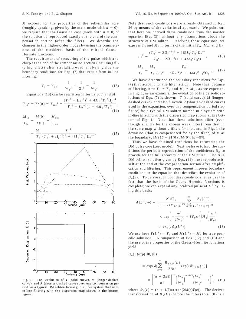
Fig. 1. Top, evolution of T (solid curve), M (longer-dashedcurve), and R (shorter-dashed curve) over one compensation pe-riod for a typical DM soliton forming in a fiber system that usesin-line filtering with the dispersion map shown in the bottomfigure.
Note that such conditions were already obtained in Ref.26 by means of the variational approach. We point outthat here we derived these conditions from the masterequation [Eq. (3)] without any assumptions about thestructure of DM soliton. Resolving these equations, weexpress T1 and M1 in terms of the initial T0 , M0 , and V f :
T12 5
~T02 2 2V f
22!2 1 16M02T0
2V f24
T02 2 2V f
22~1 1 4M02T0
2!, (16)
M1
T15
M0
T0
T04
~T02 2 2V f
22!2 1 16M02T0
2V f24 . (17)
We have determined the boundary conditions for Eqs.(7) that account for the filter action. Note that, becauseof filtering, now T1 Þ T0 and M1 Þ M0 , as we expected.In Fig. 1, as an example, the evolution of the periodic so-lutions of Eqs. (7) is shown: T (solid curve), M (longer-dashed curve), and also function R (shorter-dashed curve)used in the expansion, over one compensation period (topfigure) for a typical DM soliton formed in a system within-line filtering with the dispersion map shown at the bot-tom of Fig. 1. Note that these solutions differ (eventhough slightly for the chosen weak filter) from that inthe same map without a filter; for instance, in Fig. 1 thedeviation (that is compensated for by the filter) of M atthe boundary, @M(1) 2 M(0)#/M(0), is ;9%.
Thus we have obtained conditions for recovering theDM pulse core (zero mode). Next we have to find the con-ditions for periodic reproduction of the coefficients Bn toprovide for the full recovery of the DM pulse. The trueDM soliton solution given by Eqs. (11) must reproduce it-self at the end of the compensation section after amplifi-cation and filtering. This requirement imposes boundaryconditions on the equation that describes the evolution ofBn(z). To derive such boundary conditions let us use thefact that the basis of the Gauss–Hermite functions iscomplete; we can expand any localized pulse at L1 by us-ing this basis:
A~L1, v! 5NAT0
~1 2 2iM0T0!1/2 (n50
` Bn~L1!
~2nn!Ap!1/2
3 expS 2v2
2W02 1 iY0v2DHnS v
W0D
3 exp@ifn~L1!#. (18)
We use here T(L1) 5 T0 and M(L1) 5 M0 for true peri-odic solutions. A comparison of Eqs. (12) and (18) andthe use of the properties of the Gauss–Hermite functionsyield
Bn~0 !exp@iFn~0 !#
5 exp~d!(k50
` Bn12k~L !
2kk!exp@iFn12k~L !#
3 F ~n 1 2k !!
n! G1/2S W0
W1D n10.5S W0
2
W12 2 1 D k
, (19)
where Fn(z) 5 (n 1 1/2)arctan@2M(z)T(z)#. The derivedtransformation of Bn(L) (before the filter) to Bn(0) is a
1326 J. Opt. Soc. Am. B/Vol. 16, No. 9 /September 1999 S. K. Turitsyn and E. G. Shapiro
complimentary boundary condition to Eqs. (9), which gov-ern the evolution of coefficients Bn(z) inside the compen-sation cell. The obtained condition mixes Bn(0) andBn(L) and describes the effect of the stirring of the differ-ent modes that is due to filtering. Note that for knownA(z, t) coefficients Bn can be determined as Bn(z)5 AT exp@2iln R(z)#*2`
` dx fn(x)exp(2iMTx2)A@z, xT(z)# /Nand an arbitrary initial field distribution can be expandedin the complete set of chirped Gauss–Hermite functions.Practical guidelines for exploiting this expansion are thefollowing:
(1) Determine T and M for a given dispersion map, us-ing Eqs. (7) (with the boundary conditions accounting forthe filtering);
(2) Calculate R(z), defined as dR/dz 5 d/T2
2 ^d/T2&;(3) Present input signal A in(t) 5 A(z* , t) as
A in@t/T(z* )#, where z* is a launch point;(4) Bn(z* ) 5 AT exp@2i ln R(z* )# *2
` d xfn(x)exp@2i M(z* )T(z* )x2]A in@t/T(z* )#/N;
(5) Calculate Bn(z), using Bn(z* ) as the initial condi-tions in Eqs. (9).
To find the true periodic soliton one should solve Eqs.(9) for Bn with boundary conditions (19). Even thoughthis procedure does not look at all simple in comparisonwith direct numerics, it has an important advantage:When almost all the energy of the DM soliton is engagedin the zero self-similar mode (the term self-similar is usedhere to denote the evolution that keeps constant the prod-uct of the pulse width and the peak power of the fielduAu2), it is enough to consider only a two-mode approxima-tion to describe the most important properties of the DMsoliton. By solving the equations for two coupled Bn onecan predict the dynamics of an arbitrary initial chirpedRZ-formatted signal. A two-mode analytical approxima-tion of the DM soliton found numerically is considered inSection 4. The Gaussian approximation used in the pre-viously developed variational approach and in the moreadvanced root-mean-square momentum method50,77 isnothing more than the zero mode in the expansion of thetrue DM soliton in a complete set of chirped Gauss–Hermite functions:
A~z, t ! 5NB0
p1/4AT~z !expF2
x2
21 iMTx2
2 iR~z ! 1 ikzG , x 5t
T~z !. (20)
The higher-order modes in expansion (20) present aninherent part of the DM soliton, even though the zeromode (Gaussian) can hold most of the pulse energy. Aswas shown in Refs. 31, 68, and 70, already a few modes inthis expansion can provide an excellent description of DMpulse propagation, making this method extremely usefulfor practical numerical simulations. The two-mode ap-proximation (B0 1 B4 ; as we show below, B2 can be sub-stantially reduced by the optimal choice of T0) of the DMsoliton reads as
A~z, t ! 5NB0
p1/4AT~z !
3 H 1 1B4~4x4 2 12 x2 1 3 !exp@28iR~z !#
B02A6J
3 expF2x2
21 iMTx2 2 iR~z ! 1 ikzG . (21)
In Section 4 we verify the analytical results by numeri-cal simulations of the basic model [Eq. (2)].
4. NUMERICAL SIMULATIONS AND THEOPTIMAL EXCESS GAINTo verify our theory we performed numerical simulationsof DM soliton propagation in systems with in-line filter-ing. Although our theory can be applied to DM solitonpropagation in systems with in-line filtering for arbitraryperiodic dispersion and power maps, in the illustrationsin this paper we consider the specific example of thetransmission line analyzed in an experiment.14 A fiberwith anomalous dispersion D (1) 5 Dps/(nm 3 km) andlength 53.33 km is followed by a fiber with normal disper-sion @D (2) 5 21.67Dps/(nm 3 km)# and length 27.67 km;thus the average dispersion is zero. The amplificationdistance is equal to the compensation period, Za 5 L5 80 km. We account for the point action of the Gauss-ian filter and the optical amplifier (here both are locatedat the end of the compensation cell: zk 5 Lk, k5 0, 1, 2, ...) by multiplying the field before the filter (andthe amplifier) by exp@gL 1 d 2 v2 /(2Vf
2)#, where d is theexcess gain to compensate for the extra loss that is due tofiltering. Numerical DM solitons have been found by useof the method developed in Ref. 59. In Fig. 2 we plot theshape of the stable DM soliton shown at the beginning ofthis section (Z 5 Zk 5 80 3 k@km#; k 5 1, 2, 3, ...) in thesystem with in-line filtering that we are considering. Weshow also a first derivative of the soliton phase at thesame point. It can be seen that in the central energy-containing part the DM soliton has approximately a qua-dratic phase (which varies with z). Of course, far fromthe center the phase is not parabolic at all. In the cen-tral region where the phase is parabolic the peak powerevolves inversely proportionally to the pulse width.Practically speaking, the solution can be thought of ashaving a self-similar central core with the parabolic phaseand non-self-similar tails. Self-similarity here is definedas follows: For a self-similar pulse the product of thepulse width and the peak power of field uAu2 is constant(an increase in the pulse width leads to a proportional de-crease in the peak power and vice versa). This hypoth-esis is in agreement with the theory of the DM soliton insystems without filtering and justifies the theoretical con-sideration developed above. The central part of the soli-ton is described by the zero mode in an expansion basedon chirped Gauss–Hermite functions, and the non-self-similar tails are accounted for by higher-order modes.Figure 3 shows the three-dimensional dynamics of such aDM soliton over one compensation section. Figure 3(a)demonstrates the self-similar evolution of the soliton

S. K. Turitsyn and E. G. Shapiro Vol. 16, No. 9 /September 1999 /J. Opt. Soc. Am. B 1327
power over one period on the usual scale, and in Fig. 3bthe soliton power is shown on a logarithmic scale (dBm).The inset of Fig. 3(a) shows the evolution of the functionJ(z) defined as follows:
J~z ! 5D~z !
D~0 !,
D~z ! 5 Trms Prms 5 S E t2uAu2dt
E uAu2dtD 1/2 E uAu4dt
E uAu2dt
. (22)
The quantity J(z) characterizes the self-similar featuresof the pulse. The function J(z), therefore, also is a con-stant for the self-similar solution [for instance, for zero-mode Gaussian approximation (20)]. As can be seen fromFig. 3(a), although the DM soliton is not exactly self-similar, deviations from a zero-mode self-similar core arenot too large. In Fig. 4 we plot an approximation of thesame true soliton profile (solid curve) taken at the begin-ning of the section z 5 0 by zero-mode (crosses) and two-mode (n 5 0, 4; open squares) approximations. Onlyeven coefficients are nonzero because of the symmetry of
Fig. 2. Top, power profile of the typical stable DM soliton–forming system with in-line fixed frequency filters at the begin-ning of the compensation cell. Bottom, the soliton chirp (a firstderivative of the pulse phase over time) at z 5 0. Dispersion-allocation parameter, D 5 2.82 ps/(nm 3 km); average disper-sion, ^D& 5 0; Gaussian filter bandwidth @Bf 5 1.665 V f /(2p)#,Bf 5 375 GHz.
the solution. Note that by varying a free parameter T0in Eqs. (7) we can obtain uB2(0)u , uB4(0)u, as one can seefrom Fig. 4. This allows us to make the zero-mode ap-proximation the closest to the DM soliton. In otherwords, by minimizing B2 we incorporate its contributionto the exact solution into the periodic functions T and Mthat describe the rapid oscillations of the pulse width andthe chirp, respectively. In the inset we show the decay ofthe coefficients uBnu2 with n at z 5 0. It can be seen thatthe main zero mode has a much larger power than othermodes. This justifies using the Gaussian approximationfor a rough estimate of the soliton characteristics. How-ever, as is shown in the inset of Fig. 3(a), the solution isnot so nearly self-similar as it is for the zero-mode ap-proximation. Note that higher-order modes contributemore to the solution in the interval from the beginning ofthe period to approximately 0.25L and also closer to theend of the compensating section, as one can see from theinset of Fig. 3(a). Thus we also present an exact expres-
Fig. 3. Same soliton as in Fig. 2 but shown in a three-dimensional plot. Evolution of the soliton power over one periodis shown on (a) the usual scale and (b) a logarithmic scale (dBm).Although in the leading order the dynamics is self-similar (a),there are some non-self-similar dips in the solution, as shown in(b). Inset, evolution of the function J(z) (definition in the text)that characterizes self-similarity of the solution.

1328 J. Opt. Soc. Am. B/Vol. 16, No. 9 /September 1999 S. K. Turitsyn and E. G. Shapiro
sion for the deviation of the DM soliton from the self-similar structure that has been assumed, for instance, inRef. 26.
To obtain a true periodic DM soliton we require thatthe pulse peak power, width, and chirp be recovered atthe end of the compensation section. The advantage ofthe developed expansion in the basis of the chirpedGauss-Hermite functions is that the the point action ofthe Gaussian filter can be accounted for explicitly here,because all corresponding integrals can be calculated ana-lytically. The higher-order modes in the above expansionare an inherent part of the DM soliton, even though zeromode (Gaussian) can hold most of the pulse energy. Fil-tering causes an additional loss. To compensate for thatloss, more amplification (excess gain) is required. Wehave verified by extensive numerical simulations that fora fixed filter bandwidth a soliton survives only in a sys-tem with optimally chosen excess gain. The optimal ex-cess gain depends on the filter bandwidth and the disper-sion map parameters. The dependence of the optimalexcess gain on the filter bandwidth is shown in Fig. 5.Deviations from this curve lead to degradation and van-ishing of the pulse. Of course, degradation of the pulseoccurs after some propagation distance, and even a math-ematically unstable signal carrier can potentially be usedin practical systems. Transformation (19) accounts forthe point action of the filter. Excess gain given by d isfound from the condition recovery of the pulse power atthe end of the compensating section. In general, one cancalculate the dependence of d on the filter bandwidth fromEq. (19), making use of (n50
n5`uBn(0)u2 5 (n50n5`uBn(L)u2,
but this expression is especially simple if the main part ofthe energy is contained in the self-similar core. Excessgain then can be approximated as
d 5 20.25 ln@1 2 ~W02/V f
2!#. (23)
Figure 5 shows a comparison of the numerical resultswith analytical formula (23). Even though the DM soli-ton that we are considering is not totally self-similar, thisanalytical formula yields a very good fit to the numeri-
Fig. 4. Comparison of the zero-mode approximation (n 5 0;open circles) and the two-mode approximation (n 5 0, 4; crosses)with the profile of the true DM soliton (solid curve) in the systemwith in-line fixed frequency filters. The power profile is shownat the beginning of the compensation cell. Same parameters asin Fig. 2.
cally found curve. We note that the filtering additionallyincreases the power of the soliton (in comparison with theDM soliton that corresponds to the same dispersion mapbut without filtering). Figure 6 shows the dependence ofthe DM soliton peak power taken at the beginning of thecompensation section (solid curve) and at the first chirp-free point (dashed curve) on the filter bandwidth. Thesoliton peak power increases with decreasing filterstrength. It can be seen that the use of even a relativelyweak filter allows us to increase carrier power and, hence,to improve the system’s power margin.
5. CONCLUSIONSIn conclusion, we have presented a theory of solitonpropagation in dispersion-managed fiber communicationsystems with in-line filtering. Using a complete set ofGauss–Hermite functions, we have determined the prop-erties of a DM soliton, in particular, the dependence of theexcess gain on the filter bandwidth. This approach pre-
Fig. 5. Dependence of the optimal excess gain on the filter band-width. Open squares, direct numerical simulations; solid curve,the analytical formula. d 5 20.25 ln(12W0
2/Vf2); dispersion-
allocation parameter, D 5 2.82 ps/(nm 3 km); average disper-sion, ^D& 5 0.
Fig. 6. Dependence of power enhancement on filter bandwidth.The soliton peak power is shown at the beginning of the compen-sation section (solid curve) and at the first chirp-free point(dashed curve). The limit V f → ` corresponds to the DM solitonin the same map but without filtering.

S. K. Turitsyn and E. G. Shapiro Vol. 16, No. 9 /September 1999 /J. Opt. Soc. Am. B 1329
sents a regular way to describe the family of DM solitonsfor an arbitrary dispersion map. We have shown thatthe DM soliton is well described by a few modes in thisexpansion, justifying the use of a Gaussian trial functionin the momentum method and variational approaches.Additionally, as presented here, the method is capable ofdetermining a region of validity of the approximate ap-proach based on the use of a Gaussian approximation ofthe DM soliton. The complete basis of orthogonallychirped Gauss–Hermite functions is useful in numericalsimulations of the evolution af an arbitrarily shaped ini-tial signal along the dispersion-managed fiber lines. Wehave also demonstrated that filtering leads to an addi-tional increase in the DM soliton energy compared withthe energy of a DM soliton in a system without filters.Analytical results are supported by direct numericalsimulations.
ACKNOWLEDGMENTThis research has been supported by Volkswagen Stif-tung, by the International Association for the promotionof cooperation with scientists from the New Independentstates of the former Soviet Union under INTAS grant 96-0413, and by the Russian Foundation for Basic Researchunder grant RFBR-99-02-16688. We thank a referee ofthis paper for many valuable comments.
REFERENCES1. L. F. Mollenauer, J. P. Gordon, and P. V. Mamyshev, in Op-
tical Fiber Telecommunications, I. P. Kaminow and T. L.Koch eds. (Academic, San Diego, Calif., 1997), Vol. IIIA,Chap. 12, p. 373.
2. L. F. Mollenauer, P. V. Mamyshev, and M. J. Neubelt,‘‘Demonstration of soliton WDM transmission at up to 83 10 Gbit/s, error-free over transoceanic distances,’’ inOptical Fabrication and Testing, Vol. 2 of 1996 OSA Tech-nical Digest Series (Optical Society of America, Washing-ton, D.C., 1996), postdeadline paper PD22.
3. L. F. Mollenauer, S. G. Evangelides, Jr., and H. A. Haus,‘‘Long-distance soliton propagation using lumped amplifiersand dispersion-shifted fiber,’’ J. Lightwave Technol. 9, 194–201 (1994).
4. A. Hasegawa and Y. Kodama, ‘‘Guiding-center soliton in op-tical fibers,’’ Opt. Lett. 15, 1443–1445 (1990); ‘‘Guiding-center soliton,’’ Phys. Rev. Lett. 66, 161–164 (1991).
5. K. J. Blow and N. J. Doran, ‘‘Average soliton dynamics andthe operation of soliton systems with lumped amplifiers,’’IEEE Photonics Technol. Lett. 3, 369–371 (1991).
6. C. Lin, H. Kogelnik, and L. G. Cohen, ‘‘Optical-pulse equal-ization of low-dispersion transmission in single-mode fibersin the 1.3–1.7-mm spectral region,’’ Opt. Lett. 5, 476–479(1980).
7. A. D. Ellis and D. M. Spirit, ‘‘Unrepeated transmission over80 km standard fibre at 40 Gbit/s,’’ Electron. Lett. 30,72–74 (1994).
8. D. M. Rothnie and J. E. Midwinter, ‘‘Improved standard fi-bre performance by positioning the dispersion compensat-ing fibre,’’ Electron. Lett. 32, 1907–1911 (1996).
9. C. Das, U. Gaubatz, E. Gottwald, K. Kotten, F. Kuppers, A.Mattheus, and C. J. Weiske, ‘‘Straightforward upgrading oftransmission systems to 4 3 10 Gbit/s through 617 km and8 3 10 Gbit/s through 412 km of SMF,’’ Electron. Lett. 31,305–307 (1995).
10. M. Suzuki, I. Morita, N. Edagawa, S. Yamamoto, H. Taga,
and S. Akiba, ‘‘Reduction of Gordon–Haus timing jitter byperiodic dispersion compensation in soliton transmission,’’Electron. Lett. 31, 2027–2028 (1995).
11. N. Smith, F. M. Knox, N. J. Doran, K. J. Blow, and I. Ben-nion, ‘‘Enhanced power solitons in optical fiber transmis-sion line,’’ Electron. Lett. 32, 54–55 (1996).
12. I. Gabitov and S. K. Turitsyn, ‘‘Averaged pulse dynamics ina cascaded transmission system with passive dispersioncompensation,’’ Opt. Lett. 21, 327–330 (1996); ‘‘Breathingsolitons in optical fiber links,’’ JETP Lett. 63, 861–865(1996).
13. M. Nakazawa and H. Kubota, ‘‘Optical soliton communica-tion in a positively and negatively dispersion-allocated op-tical fiber transmission line,’’ Electron. Lett. 31, 216–217(1995).
14. M. Nakazawa, H. Kubota, A. Sahara, and K. Tamura,‘‘Marked increase in the power margin through the use of adispersion-allocated soliton,’’ IEEE Photon. Technol. Lett.8, 452–454 (1996).
15. N. S. Bergano, C. Davidson, M. Ma, A. Pilipetskii, S. Evan-gelides, H. Kidorf, J. Darcie, E. Golovchenko, K. Rottwitt,P. Corbett, R. Menges, M. Mils, B. Pedersen, D. Peckham,A. Abramov, and A. Vengsarkar, ‘‘320 Gb/s WDM transmis-sion (64 3 5 Gb/s) over 7200 km using large mode fiberspans and chirped return-to-zero signals,’’ in Optical FiberCommunication Conference (OFC), Vol. 2 of 1998 OSATechnical Digest Series (Optical Society of America, Wash-ington, D.C., 1998), postdeadline paper PD12.
16. N. Robinson, G. Davis, J. Fee, G. Grasso, P. Franco, A. Zuc-cala, A. Cavaciuti, M. Macchi, A. Schiffini, L. Bonato, andR. Corsini, ‘‘4 3 SONET OC-192 field installed dispersionmanaged soliton system over 450 km of standard fiber inthe 1550 nm erbium band,’’ in Optical Fiber Communica-tion Conference (OFC), Vol. 2 of 1998 OSA Technical DigestSeries (Optical Society of America, Washington, D.C.,1998), postdeadline paper PD19.
17. H. A. Haus, K. Tamura, L. E. Nelson, and E. P. Ippen,‘‘Stretched-pulse additive pulse mode-locking in fiber ringlasers: theory and experiment,’’ IEEE J. Quantum Elec-tron. 31, 591–603 (1995).
18. R. Kashyap, S. V. Chernikov, P. F. McKee, and J. R. Taylor,‘‘30 ps chromatic dispersion compensation of 400 fs pulsesat 100 Gbit/s in optical fibers using an all photoinducedchirped reflection grating,’’ Electron. Lett. 30, 1078–1080(1994).
19. M. Nakazawa, K. Suzuki, H. Kubota, and E. Yamada, ‘‘60G/bits WDM (20 G/bits 3 3 unequally spaced channels) soli-ton transmission over 10000 km using in-line synchronousmodulation and optical filtering,’’ Electron. Lett. 32, 1686–1688 (1996).
20. M. Suzuki, I. Morita, K. Tanaka, N. Edagawa, S. Yama-moto, and S. Akiba, ‘‘160 Gbit/s (8 3 20 Gbit/s) solitonWDM transmission experiments using dispersion flattenedfibre and periodic dispersion compensation,’’ presented atthe 1997 European Conference on Optical Communications,Edinburgh, September 19–23, 1997.
21. D. Le Guen, F. Favre, M. L. Moulinard, M. Henry, F.Devaux, and T. Georges, ‘‘320 Gbit/s soliton WDM trans-mission over 1100 km with 100 km dispersion-compensatedspans of standard fibre,’’ presented at the 1997 EuropeanConference on Optical Communications, Edinburgh,September 19–23, 1997.
22. N. S. Bergano, C. R. Davidson, A. Mills, P. C. Corbett, S. G.Evangelides, B. Pedersen, R. Menges, J. L. Ztskind, J. W.Sulhoff, A. K. Srivastava, C. Wolf, and J. Judkins, ‘‘Long-haul WDM transmission using optimum channel modula-tion: a 160 Gb/s (32 3 5 Gb/s) 9,3000 km demonstration,’’in Optical Fiber Communication Conference, Vol. 6 of 1997OSA Technical Digest Series (Optical Society of America,Washington, D.C., 1997), postdeadline paper PD16.
23. O. Leclerc and E. Desurvire, ‘‘Performance limits in 80–160Gbit/s (N 3 20 Gbit/s) regenerated WDM soliton transmis-sion,’’ presented at the 1997 European Conference on Opti-cal Communications, Edinburgh, September 19–23, 1997.
24. E. A. Golovchenko, J. M. Jacob, A. N. Pilipetskii, C. R.

1330 J. Opt. Soc. Am. B/Vol. 16, No. 9 /September 1999 S. K. Turitsyn and E. G. Shapiro
Menyuk, and G. M. Carter, ‘‘Dispersion-managed solitonsin a fiber loop with in-line filtering,’’ Opt. Lett. 22, 289–291(1997).
25. E. A. Golovchenko, A. N. Pilipetskii, and C. R. Menyuk,‘‘Dispersion-managed soliton interactions in optical fibers,’’Opt. Lett. 22, 793–795 (1997).
26. M. Matsumoto, ‘‘Effects of guiding filters on stretched-pulsetransmission in dispersion-managed fibres,’’ Electron. Lett.33, 1718–1719 (1997).
27. S. Wabnitz, ‘‘Stabilization of sliding-filtered soliton WDMtransmissions by dispersion compensating fibers,’’ Opt.Lett. 21, 638–640 (1996).
28. A. B. Grudinin, M. Durkin, M. Ibsen, R. I. Laming, A.Schiffini, P. Franco, E. Grandi, and M. Romagnoli,‘‘Straight-line 10 Gbit/s soliton transmission over 100 km ofstandard fibre with in-line chirped fibre grating for partialdispersion compensation,’’ Electron. Lett. 33, 1572–1573(1997).
29. M. J. Cole, H. Geiger, R. I. Laming, S. Y. Set, M. N. Zervas,W. H. Loh, and V. Gusmeroli, ‘‘Broadband dispersion-compensating chirped fibre gratings in 10 Gbit/s NRZ 110km non-dispersion-shifted fibre link operating at 1.55 mm,’’Electron. Lett. 33, 70–71 (1997).
30. D. Breuer, K. Juergensen, F. Kueppers, A. Mattheus, I. Ga-bitov, and S. K. Turitsyn, ‘‘Optimal schemes for dispersioncompensation of standard monomode fiber based links,’’Opt. Commun. 140, 15–18 (1997).
31. S. K. Turitsyn and V. K. Mezentsev, ‘‘Dynamics of self-similar dispersion-managed soliton presented in the basisof chirped Gauss–Hermite functions,’’ JETP Lett. 67, 640–645 (1998).
32. F. Matera and M. Settembre, ‘‘Comparison of the perfor-mance of optically amplified transmission systems,’’ J.Lightwave Technol. 14, 1–12 (1996).
33. A. Mattheus and S. K. Turitsyn, ‘‘Pulse interaction in non-linear communication systems based on standard mono-mode fibres,’’ presented at the 1993 European Conferenceon Optical, Montreux, Switzerland, September 12–16,1993.
34. F. M. Knox, W. Forysiak, and N. J. Doran, ‘‘10 Gbit/s solitoncommunication systems over standard fibre at 1.55 mm andthe use of dispersion compensation,’’ IEEE J. LightwaveTechnol. 13, 1955–1963 (1995).
35. N. J. Smith, N. J. Doran, F. M. Knox, and W. Forysiak, ‘‘En-ergy scaling characteristics of solitons in stronglydispersion-managed fibers,’’ Opt. Lett. 21, 1981–1984(1997).
36. T. Georges and B. Charbonnier, ‘‘Reduction of the disper-sive wave in periodically amplified links with initiallychirped solitons,’’ IEEE Photon. Technol. Lett. 9, 127–128(1997).
37. T. Georges and F. Favre, ‘‘Transmission systems based ondispersion-managed solitons: theory and experiment,’’presented at the Second International Symposium on Phys-ics and Applications of Optical Solitons in Fibers, Kyoto,Japan, November, 1997.
38. T. Georges, ‘‘Soliton interaction in dispersion-managedlinks,’’ J. Opt. Soc. Am. B 15, 1553–1560 (1998).
39. T. Georges, ‘‘Extended path-averaged soliton regime inhighly dispersive fibers,’’ Opt. Lett. 22, 679–681 (1997).
40. I. Gabitov, E. G. Shapiro, and S. K. Turitsyn, ‘‘Optical pulsedynamics in fiber links with dispersion compensation,’’ Opt.Commun. 134, 317–329 (1996); ‘‘Asymptotic breathingpulse in optical transmission systems with dispersion com-pensation,’’ Phys. Rev. E 55, 3624–3633 (1997).
41. J. M. Jacob, E. A. Golovchenko, A. N. Pilipetskii, G. M.Carter, and C. R. Menyuk, ‘‘Experimental demonstration ofsoliton transmission over 28 Mm using mostly normal dis-persion fiber,’’ IEEE Photon. Technol. Lett. 9, 130–132(1997).
42. M. Matsumoto and H. A. Haus, ‘‘Stretched-pulse optical fi-ber communications,’’ IEEE Photon. Technol. Lett. 9, 785–788 (1997).
43. S. K. Turitsyn, ‘‘Theory of averaged pulse propagation inhigh-bit-rate optical transmission systems with strong dis-persion management,’’ JETP Lett. 65, 845–851 (1997).
44. T. S. Yang and W. L. Kath, ‘‘Analysis of enhanced-powersolitons in dispersion-managed optical fibers,’’ Opt. Lett.22, 985–987 (1997).
45. D. Breuer, F. Kueppers, A. Mattheus, E. G. Shapiro, I. Ga-bitov, and S. K. Turitsyn, ‘‘Symmetrical dispersion compen-sation for standard monomode-fiber-based communicationsystems with large amplifying spacing,’’ Opt. Lett. 22, 546–549 (1997).
46. M. Matsumoto, ‘‘Theory of stretched-pulse transmission indispersion-managed fibers,’’ Opt. Lett. 22, 1238–1240(1997).
47. A. Sahara, H. Kubota, and M. Nakazawa, ‘‘Optimum fiberdispersion for two-step dispersion-allocated optical soliton,RZ at zero GVD and NRZ systems,’’ IEEE Photon. Technol.Lett. 9, 1179–1181 (1997).
48. S. Kumar and A. Hasegawa, ‘‘Quasi-soliton propagation indispersion managed optical fibers,’’ Opt. Lett. 22, 372–375(1997).
49. A. Hasegawa, Y. Kodama, and A. Maruta, ‘‘Recent progressin dispersion-managed soliton transmission technologies,’’Opt. Fiber Technol.: Mater., Devices Syst. 3, 197–213(1997).
50. E. Shapiro and S. K. Turitsyn, ‘‘Theory of guiding-centerbreathing soliton propagation in optical communicationsystems with strong dispersion management,’’ Opt. Lett.22, 1544–1547 (1997).
51. E. Shapiro and S. K. Turitsyn, ‘‘Enhanced power breathingsoliton in communication systems with dispersion manage-ment,’’ Phys. Rev. E 56, R4951–R4954 (1997).
52. J. N. Kutz, P. Holmes, S. G. Evangelides, Jr., and J. P. Gor-don, ‘‘Hamiltonian dynamics of dispersion managed breath-ers,’’ J. Opt. Soc. Am. B 15, 87–96 (1997).
53. J. N. Kutz and S. G. Evangelides, Jr., ‘‘Dispersion managedbreathers with average normal dispersion,’’ Opt. Lett. 23,685–688 (1998).
54. J. N. Kutz and A. Wai, ‘‘Noise-induced amplitude and chirpjitter in dispersion-managed soliton communications,’’ Opt.Lett. 23, 1022–1025 (1998).
55. T. S. Yang, W. L. Kath, and S. K. Turitsyn, ‘‘Optimal dis-persion maps for wavelength-division-multiplexed solitontransmission,’’ Opt. Lett. 23, 597–599 (1998).
56. V. S. Grigoryan, T. Yu, E. A. Golovchenko, C. R. Menyuk,and A. N. Pilipetskii, ‘‘Dispersion-managed soliton dynam-ics,’’ Opt. Lett. 22, 1609–1611 (1997).
57. V. S. Grigoryan and C. R. Menyuk, ‘‘Dispersion-managedsoliton at normal average dispersion,’’ Opt. Lett. 23, 609–611 (1998).
58. S. K. Turitsyn and E. G. Shapiro, ‘‘Variational approach tothe design of optical communication systems with disper-sion management,’’ Opt. Fiber Technol.: Mater., DevicesSyst. 4, 151–168 (1998).
59. J. H. B. Nijhof, N. J. Doran, W. Forysiak, and F. M. Knox,‘‘Stable soliton-like propagation in dispersion managed sys-tems with net anomalous, zero and normal dispersion,’’Electron. Lett. 33, 1726–1727 (1997).
60. J. H. B. Nijhof, N. J. Doran, W. Forysiak, and A. Berntson,‘‘Energy enhancement of dispersion-managed solitons andWDM,’’ Electron. Lett. 34, 481–482 (1998).
61. J. P. Gordon, ‘‘Interaction forces among solitons in opticalfibers,’’ Opt. Lett. 8, 596–598 (1983).
62. M. Wald, I. M. Uzunov, F. Lederer, and S. Wabnitz, ‘‘Opti-mization of periodically dispersion compensated breathingsoliton transmissions,’’ IEEE Photon. Technol. Lett. 9,1670–1672 (1997).
63. S. K. Turitsyn, I. Gabitov, E. W. Laedke, V. K. Mezentsev,S. L. Musher, E. G. Shapiro, T. Schafer, and K. H.Spatschek, ‘‘Variational approach to optical pulse propaga-tion in dispersion compensated transmission systems,’’ Opt.Commun. 151, 117–142 (1998).
64. S. K. Turitsyn and E. G. Shapiro, ‘‘Dispersion-managedsoliton in optical amplifier transmission systems with zeroaverage dispersion,’’ Opt. Lett. 23, 682–684 (1998).
65. S. K. Turitsyn, N. F. Smyth, and E. G. Turitsyna, ‘‘Solitarywaves in nonlinear dispersive systems with zero averagedispersion,’’ Phys. Rev. E 58, R44–R48 (1998).

S. K. Turitsyn and E. G. Shapiro Vol. 16, No. 9 /September 1999 /J. Opt. Soc. Am. B 1331
66. S. K. Turitsyn, A. B. Aceves, C. K. R. T. Jones, and V. Zhar-nitsky, ‘‘Average dynamics of the optical soliton in commu-nication lines with dispersion management: analytical re-sults,’’ Phys. Rev. E 58, R48–R52 (1998).
67. T. Lakoba, J. Yang, D. J. Kaup, and B. A. Malomed, ‘‘Con-ditions for stationary pulse propagation in the strong dis-persion management regime,’’ Opt. Commun. 149, 366–374(1998).
68. T. Lakoba and D. J. Kaup, ‘‘Shape of stationary pulse instrong dispersion management regime,’’ Electron. Lett. 34,1124–1126 (1998).
69. T. Lakoba and D. J. Kaup, ‘‘Hermite–Gaussian expansionfor pulse propagation in strongly dispersion managed fi-bers,’’ Phys. Rev. E 58, 6728–6736 (1998).
70. S. K. Turitsyn, T. Schafer, and V. K. Mezentsev, ‘‘Self-similar core and oscillatory tails of a path-averaged chirpeddispersion-managed optical pulse,’’ Opt. Lett. 23, 1351–1353 (1998).
71. S. K. Turitsyn, ‘‘Self-similar dynamics and oscillatory tailsof a breathing soliton in systems with varying dispersion,’’Phys. Rev. E 58, R1256–R1260 (1998).
72. V. E. Zakharov and A. B. Shabat, ‘‘Exact theory of twodimensional self-focusing and one-dimensional self-
modulation of waves in nonlinear media,’’ Zh. Eksp. Teor.Fiz. 61, 118–134 (1971).
73. P. Lazaridis, G. Debarge, and P. Gallion, ‘‘Exact solutionsfor linear propagation of chirped pulses using a chirpedGauss–Hermite orthogonal basis,’’ Opt. Lett. 22, 685–687(1997).
74. M. Matsumoto, ‘‘Effect of guiding filters on stretched-pulsetransmission in dispersion-managed fibers,’’ Electron. Lett.33, 1718–1720 (1997).
75. L. F. Mollenauer, P. V. Mamyshev, and J. P. Gordon, ‘‘Ef-fect of guiding filters on the behavior of dispersion-managedsolitons,’’ Opt. Lett. 24, 220–222 (1999).
76. J. P. Gordon and L. F. Mollenauer, ‘‘Scheme for the charac-terization of dispersion-managed solitons,’’ Opt. Lett. 24,223–225 (1999).
77. S. K. Turitsyn, E. G. Shapiro, and V. K. Mezentsev,‘‘Dispersion-managed solitons and optimization of the dis-persion management,’’ Opt. Fiber Technol.: Mater., DevicesSyst. 4, 384–452 (1998).
78. A. Mecozzi, J. D. Moores, H. A. Haus, and Y. Lai, ‘‘Solitontransmission control,’’ Opt. Lett. 16, 1841–1843 (1991);‘‘Modulation and filtering control of soliton transmission,’’J. Opt. Soc. Am. B 9, 1350–1357 (1992).