displacement method of analysis slope deflection...
TRANSCRIPT

Displacement Method of AnalysisSlope Deflection Method
Chapter 11

Displacement Method of Analysis
• Two main methods of analyzing indeterminate structure
– Force method • The method of consistent deformations & the equation of three
moment
• The primary unknowns are forces or moments
– Displacement method
• The slope-deflection method & the moment distribution method
• The primary unknown is displacements (rotation & deflection)
• It is particularly useful for the analysis of highly statically indeterminate structures
• Easily programmed on a computer & used to analyze a wide range of indeterminate structures

Displacement Method of Analysis
• Degree of Freedom
– The number of possible joint rotations & independent joint translations in a structure is called the degree of freedom of the structure
– In three dimensions each node on a frame can have at most three linear displacements & three rotational displacements.
– In two dimension each node can have at most two linear displacements & one rotational displacement.
DOF = n J– R
- n number of possible joint’s movements
- J number of joints
- R number of restrained movements

Displacement Method of Analysis
• Degree of Freedom
DOF = n J– R- n number of possible joint’s movements
- n = 2 for two dimensional truss structures- n = 3 for three dimensional truss structures- n= 3 for two dimensional frame structures- n= 6 for three dimensional frame structures
- J number of joints- R number of restrained movements
• Neglecting Axial deformationDOF = n J– R – m
- m number of members

Displacement Method of Analysis
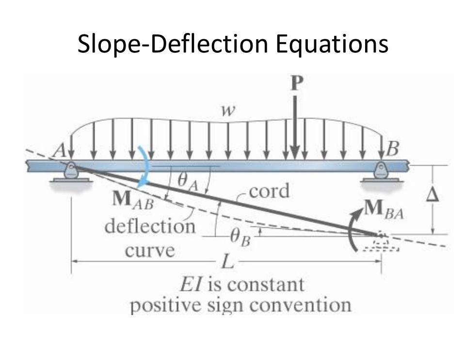
Slope-Deflection Equations
•Derivation

Slope-Deflection Equations
• Angular Displacement at A, A
'
'
1 1 20 0
2 3
4
2 3
1 1 2
2&
0 02 3 2 3
AB B
AB A
AA
BA AB
A
B
A
A
B
M L M LM L L
EI EI
M L M LM L L L
E
EI EIM M
L L
I EI

Slope-Deflection Equations
• Angular Displacement at B, B
4
2
BA B
AB B
EIM
L
EIM
L

Slope-Deflection Equations• Relative Linear Displacement
1 2 10.
2 3 2 3
M L M LL L
EI EI
' 0.BM
2
6AB BA
EIM M M
L

Slope-Deflection Equations• Fixed-End Moment
1 12 0.
2 2
PL ML L
EI EI
0.yF
8
PLM
Fixed-End moment
FEM

Slope-Deflection Equations
( )
( )
AB AB
BA BA
M FEM
M FEM

Slope-Deflection EquationsFixed-End Moment

Slope-Deflection Equations
• Slope-deflection equations
– The resultant moment (adding all equations together)
• Lets represent the member stiffness as k = I/L &
• The span ration due to displacement as = /L
• Referring to one end of the span as near end (N) & the other end as the far end (F).
– Rewrite the equations
2 2 3 ( )AB A B AB
IM E FEM
L L
2 2 3 ( )BA B A BA
IM E FEM
L L
2 2 3 ( )
2 2 3 ( )
N N F N
F F N F
M EK FEM
M EK FEM

Slope-Deflection Equations
• Slope-deflection equations for pin supported End Span
– If the far end is a pin or a roller support
– Multiply the first equation by 2 and subtracting the second equation from it
2 2 3 ( ) '
0 2 2 3 0
N N F N
F N
M EK FEM
EK
3 ( ) 'N N NM EK FEM

Fixed End Moment Table

Fixed End Moment Table

Fixed End Moment Table- Continue

Summary
2 2 3 ( )
2 2 3 ( )
N N F N
F F N F
M EK FEM
M EK FEM
3 ( ) 'N N NM EK FEM

Slope-Deflection Equations
– MN, MF = the internal moment in the near & far end of the span. • Considered positive when acting in a clockwise direction
– E, k = modulus of elasticity of material & span stiffness k = I/L
– N, F = near & far end slope of the span at the supports in radians.
• Considered positive when acting in a clockwise direction
– = span ration due to a linear displacement / L.
• If the right end of a member sinks with respect the the left end the sign is positive

Slope-Deflection EquationsSteps to analyzing beams using this method
– Find the fixed end moments of each span (both ends left & right)
– Apply the slope deflection equation on each span & identify the unknowns
– Write down the joint equilibrium equations
– Solve the equilibrium equations to get the unknown rotation & deflections
– Determine the end moments and then treat each span as simply supported beam subjected to given load & end moments so you can workout the reactions & draw the bending moment & shear force diagram

Draw the bending moment & shear force diagram.
Fixed End Moment
2
4 42 . 2 .
8
2 66 . 6 .
12
AB BA
BC CB
FEM t m FEM t m
FEM t m FEM t m
Slope Deflection Equations
0
0
0
0
2 2 0 2 0.5 24
2 2 0 2 24
2 42 2 0 6 6
6 3
2 22 2 0 6 6
6 3
A
A
C
C
AB A B AB B
BA A B BA B
BC B C BC B
CB B C CB B
IM E M EI
IM E M EI
IM E M EI
IM E M EI
4m 6m
4t2t/m
A B C2II
Example 1

Joint Equilibrium Equations
1.70.5 2 1.15 .
1.72 3.7 .
3.7 .
2 1.76 7.1 .
3
AB
BA
BC
CB
M EI t mEI
M EI t mEI
M t m
M EI t mEI
0
4 1.72 6 0.
3
BA BC
B B B
M M
EI EIEI
Joint B
Substituting in slope deflection equations
Computing The Reactions
RA
1.15
4t
RB1
3.7
1
1.15 4 2 3.71.36
4
4 1.36 2.64
A
B
R t
R t

2
2 6 3 3.7 7.15.43
6
2 6 5.43 6.57
B
C
R t
R t
RB2
3.7
2t/m
RC
7.1
6.57
5.43
2.64
1.36
--
++
7.1
3.7
1.15
3.79
1.57+
+
---

• Determine the internal moments in the beam at the supports.
Fixed End Moment2
2
2
2
2
60 4 226.67 .
6
60 2 453.33 .
6
30 6135 .
8
AB
BA
BC
FEM kN m
FEM kN m
FEM kN m
Slope Deflection Equations
0
0
12 2 0 26.67 26.67
6 3
22 2 0 53.33 53.33
6 3
13 0 135 135
6 2
A
A
AB A B AB B
BA A B BA B
BC B BC B
IM E M EI
IM E M EI
IM E M EI
60kN
6m 6m
30kN/m
A B CII
4m
Example 2

0
2 1 753.33 135 0 81.67
3 2 6
70
BA BC
B B B
B
M M
EI EI EI
EI
Joint Equilibrium Equations
1(70) 26.67 3.33 .
3
2(70) 53.33 100 .
3
1(70) 135 100 .
2
AB
BA
BC
M kN m
M kN m
M kN m
Joint B
Substituting in slope deflection equations

Example 3
• Example 2: Determine the internal moments in the beam at the supports
– Support A; downward movement of 0.3cm & clockwise rotation of 0.001 rad. Support B; downward movement of 1.2cm. Support C downward movement of 0.6cm. EI = 5000 t.m2
6m 6m
A B C
II
Fixed End Moment
0.AB BA BC CBFEM FEM FEM FEM
Displacements:
0.001
1.2 0.30.0015
600
0.6 1.20.001
600
A
AB
BC
Slope Deflection Equations
2 50002 0.001 3 0.0015
6
2 50002 0.001 3 0.0015
6
AB B
BA B
M
M

3 5000
0.0016
BC BM
Joint Equilibrium Equations
0
7 0.004 0
0.00057
BA BC
B
B
M M
rad
Joint B

Substituting in slope deflection equations
2 50002 0.001 0.00057 3 0.0015 3.22 .
6
2 50002 0.00057 0.001 3 0.0015 3.93 .
6
3 50000.00057 0.001 3.93 .
6
AB
BA
BC
M t m
M t m
M t m

Example 1b
0.0AB BAFEM FEM
0.0A C

Slope Deflection Equations

Equilibrium Equations

Example 2b


Example 3b


Example 4


• Analysis of Frames Without Sway– The side movement of the end of a column in a frame is called SWAY.

– Determine the moment at each joint of the frame. EI is constant
25 24 880 .
96BCFEM kN m
Fixed End Moment0.AB BAFEM FEM
25 24 880 .
96CBFEM kN m
0.CD DCFEM FEM
A= 0. 2 0. 0. 0
12AB B
IM E
0.1667AB BM EI
Slope Deflection Equations
A= 0. 2 2 0 0. 0
12BA B
IM E
0.333BA BM EI
Example 5

0.333 0.5 0.25 80 0.C C BEI EI EI
2 2 0 808
BC B C
IM E
0.5 0.25 80BC B CM EI EI
2 2 0 808
CB C B
IM E
0.5 0.25 80CB C BM EI EI
D= 0. 2 2 0 0. 0
12CD C
IM E
0.333CD CM EI
D= 0. 2 0 0. 0
12DC C
IM E
0.1667DC CM EI
Joint Equilibrium Equations
0BA BCM M
Joint B
0.333 0.5 0.25 80 0.B B CEI EI EI 0.833 0.25 80B CEI EI
0CB CDM M
Joint C
0.833 0.25 80C BEI EI

22.9 .
45.7 .
45.7 .
45.7 .
45.7 .
22.9 .
AB
BA
BC
CB
CD
DC
M kN m
M kN m
M kN m
M kN m
M kN m
M kN m
Substituting in slope deflection equations
Two equation & two unknown 137.1
B CEI
45.7 45.7
22.9
82.3
22.9

Example 6


2I
2I
II
I
A
B
E
C
F
D
– Draw the bending moment diagram
30kN20kN48kN/m
2
2
20 1 28.89 .
3BAFEM kN m
Fixed End Moment2
2
20 2 14.44 .
3ABFEM kN m
248 464 .
12BCFEM kN m
64 .CBFEM kN m
0BE EB CF FCFEM FEM FEM FEM
30 2 60 .CDM kN m
A= 0.Slope Deflection Equations
2 2 0 4.443
AB A B
IM E
24.44
3AB BM EI
4m3m
4m 2m3m
1m
Example 6b

A= 0. 2 2 0 8.89
3BA A B
IM E
48.89
3BA BM EI
2
2 2 0 644
BC B C
IM E
2 64BC B CM EI EI
2
2 2 0 644
CB B C
IM E
2 64CB B CM EI EI
2 2 0 03
BE B E
IM E
4
3BE BM EI
E= 0.
2 2 0 03
EB E B
IM E
2
3EB BM EI
E= 0.
2
2 2 0 04
CF C F
IM E
2CF CM EI
F= 0.
2
2 2 0 04
FC F C
IM E
FC CM EI
F= 0.

Equilibrium Equations
0BA BC BEM M M
4.67 55.11B CEI EI
Joint B
4 48.89 2 64 0
3 3B B C BEI EI EI EI
0CB CF CDM M M
4 4B CEI EI
Joint C
2 64 2 60 0B C CEI EI EI
Two equation & two unknown
4.18CEI 12.70BEI
Substituting in slope deflection equations
212.7 4.44 4.03 .
3ABM kN m
412.70 8.89 25.83
3BAM kNm
2 12.7 4.18 64 42.77 .BCM kN m
12.7 2 ( 4.18) 64 68.34 .CBM kN m

4.18
8.35
60
68.35
42.77
25.83
16.94
4.03
8.47
412.70 16.94 .
3BEM kN m
212.70 8.47 .
3EBM kN m
2 ( 4.18) 8.35 .CFM EI kN m
4.18 .FCM kN m

Slope Deflection (Frame with Sway) • Analysis of Frames with Sway

Fixed End Moment
2 0. 3 012 12
AB B
IM E
Slope Deflection Equations
1 1
6 24BEI EI
As there is no span loading in any
of the member FEM for all the
members is zero
2 2 0. 3 012 12
BA B
IM E
1 1
3 24BEI EI
– Draw the bending moment diagram. EI constant
Example 7

0. 4 22 2 3 0
15 15 15 15BC B C B C
IM E EI EI
2 4
2 2 0 015 15 15
CB C B B C
IM E EI EI
2 12 2 0 3 0.
18 18 9 54CD C C
IM E EI EI
1 12 0 3 0
18 18 9 54DC C C
IM E EI EI
Equilibrium Equations
0BA BCM M Joint B MB = 0
1 1 4 20.
3 24 15 15B B CEI EI EI EI
14.4 3.2 0B CEI EI EI 1
0CB CDM M
Joint C MC = 0

Three unknown & just two equations so we need
another equilibrium equation. Let take Fx = 0.
2 4 2 10.
15 15 9 54B C CEI EI EI EI
7.2 26.4 0B CEI EI EI 2
40 0.A DH H
12
BA ABA
M MH
18
CD DCD
M MH
40 18 1.5 0.BA AB CD DCM M M M
1 1 1 1720 1.5
3 24 6 24B BEI EI EI EI
2 1 1 10.
9 54 9 54C CEI EI EI EI
0.162 0.75 0.333 720B CEI EI EI 3

Now solve the three equation
1 14.4 3.2 0
1 7.2 26.4 0
0.162 0.75 0.333 720
B
C
EI
EI
EI
136.2CEI
438.9BEI
6756.6EI
Substituting in slope deflection equations
208 .ABM kN m
135 .BAM kN m
135 .BCM kN m
95 .CBM kN m
95 .CDM kN m
110 .DCM kN m

-
-+
-
+
+
110
135
135
208
95
95

220 15375 .
12BCFEM kN m
Fixed End Moment
0.AB BAFEM FEM
220 15375 .
12CBFEM kN m
0.CD DCFEM FEM
2 0. 3 012 12
AB B
IM E
Slope Deflection Equations
1 1
6 24BEI EI
– Draw the bending moment diagram. EI constant
Example 7

2 2 0. 3 012 12
BA B
IM E
1 1
3 24BEI EI
0.2 2 3 375
15 15BC B C
IM E
4 2375
15 15B CEI EI
2 2 0 37515
CB C B
IM E
2 4375
15 15B CEI EI
2 2 0 3 0.18 18
CD C
IM E
2 0 3 018 18
DC C
IM E
Equilibrium Equations
0BA BCM M Joint B MB = 0
1 1 4 2375 0.
3 24 15 15B B CEI EI EI EI
14.4 3.2 9000B CEI EI EI 1
2 1
9 54CEI EI
1 1
9 54CEI EI

Three unknown & just two equations so we need
another equilibrium equation. Let take Fx = 0.
0CB CDM M Joint C MC = 0
2 4 2 1375 0.
15 15 9 54B C CEI EI EI EI
7.2 26.4 20250B CEI EI EI 2
40 0.A DH H
12
BA ABA
M MH
18
CD DCD
M MH
40 18 1.5 0.BA AB CD DCM M M M
1 1 1 1720 1.5
3 24 6 24B BEI EI EI EI
2 1 1 10.
9 54 9 54C CEI EI EI EI
0.162 0.75 0.333 720B CEI EI EI 3

1 14.4 3.2 9000
0 7.2 23.2 29250
0 1.58 0.185 2178
B
C
EI
EI
EI
Now solve the three equation
1 14.4 3.2 9000
1 7.2 26.4 20250
0.162 0.75 0.333 720
B
C
EI
EI
EI
1 14.4 3.2 9000
0. 7.2 23.2 29250
0. 0. 5.29 4257
B
C
EI
EI
EI
R1-R2
0.162R1-R3
0.22R2-R3
4257804.7
5.29CEI
1469.6BEI
9587.2EI Substituting in slope deflection equations
1 11467.2 9587.2 155 .
6 24ABM kN m
1 11469.6 9587.2 90 .
3 24BAM kN m

4 21469.6 ( 804.7) 375 90 .
15 15BCM kN m
2 41469.6 ( 804.7) 375 356 .
15 15CBM kN m
2 1( 804.7) 9587.2 356 .
9 54CDM kN m
1 1( 804.7) 9587.2 267 .
9 54DCM kN m
267
356
90
90
155
356
--
-

Example 8


– Draw the bending moment diagram. EI constant
Fixed End Moment
As there is no span loading in any of the
member FEM for all the members is zero
12 0. 3 05 5
AB B
IM E
Slope Deflection Equations
1
2 6
5 25BEI EI
12 2 0 3 05 5
BA B
IM E
1
4 6
5 25BEI EI
Example 9

02 2 3 0
7 7BE B E
IM E
4 2
7 7B EEI EI
02 2 3 0
7 7EB E B
IM E
2 4
7 7B EEI EI
12 0. 3 05 5
FE E
IM E
1
2 6
5 25EEI EI
12 2 0 3 05 5
EF E
IM E
1
4 6
5 25EEI EI
22 2 3 05 5
BC B C
IM E
2
4 2 6
5 5 25B CEI EI EI
22 2 3 05 5
CB C B
IM E
2
2 4 6
5 5 25B CEI EI EI
02 2 3 0
7 7CD C D
IM E
4 2
7 7C DEI EI
02 2 3 0
7 7DC D C
IM E
2 4
7 7C DEI EI

22 2 3 05 5
DE D E
IM E
2
4 2 6
5 5 25D EEI EI EI
22 2 3 05 5
ED E D
IM E
2
2 4 6
5 5 25D EEI EI EI
Equilibrium Equations
0BA BC BEM M M
Joint B MB = 0
1 2
4 6 4 2 6 4 20
5 25 5 5 25 7 7B B C B EEI EI EI EI EI EI EI
1 2380 70 50 42 42 0B C EEI EI EI EI EI 1
0EB ED EFM M M
Joint E ME = 0
2 1
2 4 2 4 6 4 60
7 7 5 5 25 5 25B E D E EEI EI EI EI EI EI EI
1 250 70 380 42 42 0B D EEI EI EI EI EI 2

0CB CDM M
Joint C MC= 0
2
2 4 6 4 20
5 5 25 7 7B C C DEI EI EI EI EI
270 240 50 42 0B C DEI EI EI EI 3
0DC DEM M
Joint D MD = 0
2
2 4 4 2 60
7 7 5 5 25C D D EEI EI EI EI EI
250 240 70 42 0C D EEI EI EI EI 4
40 0B EH H
Top story FX = 0
5
CB BCB
M MH
5
DE EDE
M MH
HB HE

40 80 0A FH H
Bottom story FX = 0
5
BA ABA
M MH
5
EF FEF
M MH
HA HF
2 2
2 4 6 4 2 6200
5 5 25 5 5 25B C B CEI EI EI EI EI EI
26 6 6 6 4.8 1000B C D EEI EI EI EI EI
2 2
4 2 6 2 4 60
5 5 25 5 5 25D E D EEI EI EI EI EI EI
5
1 1
4 6 2 6600
5 25 5 25B BEI EI EI EI
1 1
4 6 2 60
5 25 5 25E EEI EI EI EI
130 30 24 15000B EEI EI EI 6

6 unknown and 6 equation
1
2
380 70 0 50 42 42 0
50 0 70 380 42 42 0
70 240 50 0 0 42 0
0 50 240 70 0 42 0
6 6 6 6 0 4.8 1000
30 0 0 30 24 0 15000
B
C
D
E
EI
EI
EI
EI
EI
EI
171.79BEI
79.80CEI
79.80DEI
171.79EEI
1 1054.46EI
2 837.29EI
Substituting in slope deflection equations
184.4 .ABM kN m
115.6 .BAM kN m
147.2 .BEM kN m
147.2 .EBM kN m
184.4 .FEM kN m
115.6 .EFM kN m
31.6 .BCM kN m
68.4 .CBM kN m
68.4 .CDM kN m
68.4 .DCM kN m
68.4 .DEM kN m
31.6 .EDM kN m

-
-
-
-
++
- ++
++
-
147.2
31.6
68.4
31.6
184.4
115.6
147.2
115.6
184.4
68.4
68.4
68.4

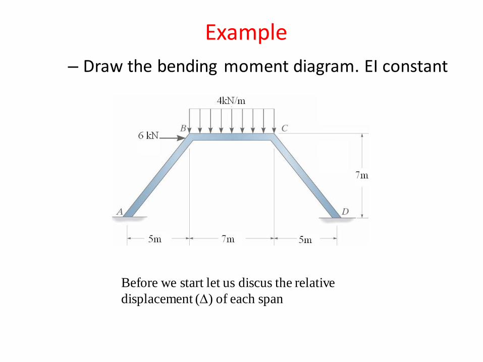
Before we start let us discus the relative
displacement () of each span
Degree of freedom
DOF = 3x4-6-3 = 3
That means we got three unknown &
we need three equations
– Draw the bending moment diagram. EI constant
Example 10

AB
The relative displacement () for span AB
is equal AB – 0. = AB (clockwise)
The relative displacement () for span BC is
equal 0. – BC = –BC (counterclockwise)
The relative displacement () for span CD
is equal 0. – (–CD)= CD (clockwise)
BC
CD
A
B
D
C
60o
take AB =
BC = AB sin30 = 0.5
CD = AB cos30 = 0.866
Let us build a relationship between AB, BC & CD
So in the slope deflection equations we will use;
as the relative displacement of span AB.
–0.5 as the relative displacement of span BC.
0.866as the relative displacement of span CD.
AB
BC
CD60o
60o
B =30o

22 42.667 .
12BCFEM t m
Fixed End Moment
0.AB BAFEM FEM
2.667.CBFEM m
0.CD DCFEM FEM
2 0. 3 03 3
AB B
IM E
Slope Deflection Equations
2 2
3 3BEI EI
2 2 0 3 03 3
BA B
IM E
4 2
3 3BEI EI
0.52 2 3 2.667
4 4BC B C
IM E
1 32.667
2 16B CEI EI EI
0.52 2 3 2.667
4 4CB B C
IM E
1 32.667
2 16B CEI EI EI

0.8662 2 0 3 0
6 6CD C
IM E
2 0.866
3 6CEI EI
0.8662 0 3 0
6 6DC C
IM E
1 0.866
3 6CEI EI
Equilibrium Equations
0BA BCM M
Joint B MB = 0
4 2 1 32.667 0
3 3 2 16B B CEI EI EI EI EI
112 24 23 128B CEI EI EI 1
0CB CDM M
Joint C MC = 0
1 3 2 0.8662.667 0
2 16 3 6B C CEI EI EI EI EI
24 80 2.072 128B CEI EI EI 2

34.5 3.1 38.375 144B CEI EI EI 3
Third Equilibrium Equations (Method 1)
21 22 12.92 11.92 96 0AB BA CD DCM M M M
6.92m
6.0m
8.0
3.0 2.0 2.0
6.0
3.0
8 t
11 12.923 6
8 2 0.0
DC CDAB BAAB DC
M MM MM M

0A DH H
Third equation FX = 0
From the free body diagram for column CD
6
CD DCD
M MH
Free body diagram for column AB
D
C
HD
CDM
DCM
A
B
HA
ABM
BAM
1.5m
2.6
m
VA
2.6 1.5 0A BA AB AH M M V
Free body diagram for Beam BC
VB
C
CBMB
BCM 2t/m
4 2 4 2 0B BC CBV M M
1.54
2.6 2.6 4
BC CBBA AB
A
M MM MH
1.54 0.
2.6 2.6 4 6
BC CBBA AB CD DCM MM M M M
4
4
BC CB
A B
M MV V
Third Equilibrium Equations (Method 2)

24 9 10.4 144BA AB BC CB CD DCM M M M M M
4 2 2 2 124 9
3 3 3 3 2B B B CEI EI EI EI EI EI
2 0.866 1 0.86610.4 144
3 6 3 6C CEI EI EI EI
3 1 32.667 2.667
16 2 16B CEI EI EI EI
34.5 3.1 38.375 144B CEI EI EI 3
Solving the three equation
112 24 23 128
24 80 2.072 128
34.5 3.1 38.375 144
B
C
EI
EI
EI
3.11BEI
2.71CEI
6.77EI

Solving the three equation
112 24 23 128
24 80 2.072 128
34.5 3.1 38.375 144
B
C
EI
EI
EI
3.11BEI
2.71CEI
6.77EI

Substituting in slope deflection equations
2.44 .ABM t m
0.36 .BAM t m
0.36 .BCM t m
2.78 .CBM t m
2.78 .CDM t m
1.88 .DCM t m A
B
D
C
_
_
+
+
2.78
1.88
2.78
0.360.36
2.442.8
Before we start let us discus the relative
displacement () of each span
– Draw the bending moment diagram. EI constant
Example

The relative displacement () for span AB
is equal AB – 0. = AB (clockwise)
The relative displacement () for span BC is equal
(– 2) – 1 = – (1+ 2) = – BC (counterclockwise)
The relative displacement () for span CD
is equal 0. – (–CD)= CD (clockwise)
BC = 1+ 2
take AB =
BC = 2(AB cos) = 2 5/8.6 = 1.163
CD = AB =
Let us build a relationship between AB, BC & CD
So in the slope deflection equations we will use;
as the relative displacement of span AB.
–1.163 as the relative displacement of span BC.
as the relative displacement of span CD.
A
B
D
C
CD
AB
1
2
AB
BC
CD
B
1
2
1 = 2 & CD = AB because of
the symmetry in the geometry

24 716.33 .
12BCFEM kN m
Fixed End Moment
0.AB BAFEM FEM
16.33 .CBFEM kN m
0.CD DCFEM FEM
2 0. 3 08.6 8.6
AB B
IM E
Slope Deflection Equations
2 6
8.6 73.96BEI EI
2 2 0 3 08.6 8.6
BA B
IM E
4 6
8.6 73.96BEI EI
1.1632 2 3 16.33
7 7BC B C
IM E
4 2 6.97816.33
7 7 49B CEI EI EI
1.1632 2 3 16.33
7 7CB C B
IM E
2 4 6.97816.33
7 7 49B CEI EI EI

2 2 0 3 08.6 8.6
CD C
IM E
4 6
8.6 73.96CEI EI
2 0 3 08.6 8.6
DC C
IM E
2 6
8.6 73.96CEI EI
Equilibrium Equations
0BA BCM M
Joint B MB = 0
4 6 4 2 6.97816.33 0
8.6 73.96 7 7 49B B CEI EI EI EI EI
103.65 28.57 6.13 1633B CEI EI EI 1
0CB CDM M
Joint C MC = 0
2 4 6.978 4 616.33 0
7 7 49 8.6 73.96B C CEI EI EI EI EI
28.57 103.65 6.13 1633B CEI EI EI 2

6 0A DH H
Third equation FX = 0
From the free body diagram for column CD
Free body diagram for column AB
A
B
HA
ABM
BAM
5m
7m
VA
7 5 0A BA AB AH M M V
Free body diagram for Beam BC
7 4 7 3.5 0B BC CBV M M
514
7 7 7
BC CBBA AB
A
M MM MH
14
7
BC CB
A B
M MV V
VB
C
CBMB
BCM 4kN/m
VC
C
HD
CDM
DCM
5m
7m
D
VD
7 5 0D CD DC DH M M V
7 4 7 3.5 0C BC CBV M M
14
7
BC CB
D C
M MV V

6 49 7 5 7 5 0BA AB BC CB CD DC BC CBM M M M M M M M
3.688 3.688 5.12 294B CEI EI EI 3
Solving the three equation
103.65 28.57 6.13 1633
28.57 103.65 6.13 1633
3.688 3.688 5.12 294
B
C
EI
EI
EI
18.897BEI
24.603CEI
61.532EI
514
7 7 7
CD DC BC CB
D
M M M MH
6 0A DH H
7 7 10 294BA AB CD DC BC CBM M M M M M
2 6 4 6 2 67 7
8.6 73.96 8.6 73.96 8.6 73.96B B CEI EI EI EI EI EI
4 6 4 2 6.978
10 16.338.6 73.96 7 7 49
C B CEI EI EI EI EI
2 4 6.97816.33 294
7 7 49B CEI EI EI

Substituting in slope deflection equations
0.6 .ABM kN m
3.8 .BAM kN m
3.8 .BCM kN m
16.43 .CBM kN m
16.43 .CDM kN m
10.71 .DCM kN m
_
+
10.71
3.8
16.43
16.43
0.6
3.8
14.4
A
B
D
C