displacements in the recovery and reinforcement of
TRANSCRIPT

Revista Ingeniería de Construcción RIC Vol 34 Nº2 2019 www.ricuc.cl
ENGLISH VERSION.....................................................................................................................................................................................................................................................
Revista Ingeniería de Construcción Vol 34 Nº2 Abril de 2019 www.ricuc.cl 205
Precision Geometric Levelling for the Control of Vertical Displacements in the Recovery and Reinforcement of Concrete Beam, a Case Study Nivelación Geométrica de Precisión para el Control de Desplazamientos Verticales en la Recuperación y Refuerzo de una Viga de Concreto, Estudio de Caso
M. Françoso *, I. Pizarro 1* **, L. de Almeida *, M. da Silva *
* Universidade Estadual de Campinas, Campinas, BRASIL ** Instituto Tecnologico de Costa Rica, Cartago, COSTA RICA
Fecha de Recepción: 29/10/2018 Fecha de Aceptación: 09/04/2019
PAG 205-214 Abstract Monitoring and control of large size civil works was an important and well known application area for topographical and geodetic methods, with a wide range of articles published. However, documented experiences applying precision geodetic methods in monitoring in a smaller scale (structural elements: beams, columns, slabs, etc.) are sparse. The main objective of this study is to evaluate and compare the use of precision geometric levelling technique with instrumentation with displacement transducers (structural instrumentation method) in vertical displacement control in a concrete beam with excessive deformation, being subjected to recovery processes and reinforcement. Although precision geometric levelling is not considered a modern technique in the structures monitoring, it is cost-effective feasible, accurate, and highly precise, with acceptable uncertainties and results, considering procedures normally followed in the processes of recovery and reinforcement related to this type of works. The results have shown that precision geometric levelling is an effective alternative, with remarkable advantages in assembling times and installation, as well as in monitoring post-recovery process of structures (medium and long term), and as the possibility of establishing a correlation between the behaviour of the monitored points. In addition, precision geometric levelling is a valid alternative to be implemented jointly with structural instrumentation techniques, especially where redundancy needs to be obtained in the observations. Keywords: Geometric levelling, monitoring, vertical displacements, structural elements Resumen El control y monitoreo de obras civiles de gran tamaño siempre fue una importante y conocida área de aplicación de métodos geodésicos y topográficos, con una amplia gama de trabajos publicados. Sin embargo, las experiencias documentadas usando métodos geodésicos de precisión en el monitoreo a una escala menor (elementos estructurales como: vigas, columnas, losas, etc.), son escasos. El objetivo del presente trabajo es evaluar y comparar el uso de la nivelación geométrica de precisión con la instrumentación con transductores de desplazamientos (método de instrumentación estructural), en el control de desplazamientos verticales en una viga de concreto con excesivas deformaciones, sujeta a trabajos de recuperación y refuerzo. Si bien la nivelación geométrica de precisión no es considerada una técnica moderna en el monitoreo de estructuras, es económicamente factible, con alta precisión e exactitud, con aceptables resultados e incertidumbres, considerando los procedimientos que normalmente se siguen en trabajos de recuperación y refuerzo de este tipo de obras. Los resultados demostraron que la nivelación geométrica de precisión es una alternativa útil, con notables ventajas en el tiempo de montaje e instalación, así como en el monitoreo de la estructura post-recuperación (a mediano y largo plazo) y con la posibilidad de establecer correlación entre el comportamiento de los puntos monitoreados. Además, la nivelación geométrica de precisión es una opción válida para ser implementada en conjunto con técnicas de instrumentación estructural, especialmente cuando se requiere redundancia en las observaciones Palabras clave: Nivelación geométrica, monitoreo, desplazamientos verticales, elementos estructurales
1. Introduction
A high percentage of the pathological manifestations of the buildings are originated mainly throughout project phase by conception mistakes and during the execution of the work, thus increasing considerably the costs and causing a lot of troubles during the utilization.
One of the effects associated to the occurrence of pathological manifestations in concrete structural elements are their excessive deformation. Beams and slabs are deformed by the load imposed, by the creep of concrete effect, by temperature effect, among others. Such deformations, in general terms, can be understood as a response to the external load and environment exposure
(Baroni, 2003), thus impacting not only the performance of the part itself, but also the structure as whole.
The unsatisfactory performance of a structure does not mean that it is doomed to fail and is wholly improper, even when their lives are started out in improper ways, due to project or execution failure. In most cases, the immediate technical intervention enables the structure’s rehabilitation, aiming at re-establishing the originally defined conditions in the project (recovery), or it allows the adjustments of the resistant capacity of the structural elements on account of the use (reinforcement) (Reis, 2001).
The structure’s rehabilitation process starts by determining the real conditions, aiming at evaluating the existent abnormalities, the causes, measures and methods to be considered for recovery or reinforcement. There are three basic stages: data survey, analysis and diagnosis.
After an accurate diagnosis, a suitable technique is chosen, which includes the selection of materials, equipment, and labour needed for the work’s execution (Souza and
1 Corresponding author:
Universidade Estadual de Campinas, Campinas, BRASIL E-mail: [email protected]

206 Revista Ingeniería de Construcción Vol 34 Nº2 Abril de 2019 www.ricuc.cl
Ripper 1998). In the recovery of great size constructions, usually, the data survey stage and the adopted solution execution, involve the structure and its elements’ monitoring and control.
The monitoring of the deformations or displacements allow the follow up of the structure’s behaviour, besides contributing with information which can offer support in the decision making process, also ensuring the correct execution of the recovery works, as in accordance with correction project.
Traditionally, great size constructions are monitored through techniques and high precision and accuracy geodetic equipment, including precision levels, total stations, laser scanner and photogrammetric equipment (Mills and Barber, 2004) (Costantino and Angelini, 2014) (Sabuncu and Ozener, 2014) (Beshr, 2015) (Capra et al., 2015) (Mill et al., 2015) (Lienhart, 2017) (Lienhart et al., 2017) (Kovačič and Motoh, 2019). More recently, these techniques have been implemented with the use of satellite positioning, GNSS technology (Global Navigation Satellite System) (Acosta et al., 2018). On a smaller scale, more specifically of elements which make up a structure (beams, columns, foundations, slabs etc.), monitoring has been carried out by employing structural instrumentation techniques with the use of deformation sensors, displacement transducers, accelerometers, inclinometers, extensometers, etc., (Erol, 2010) (Detchev et al., 2011) (Díaz et al., 2018) (Kovačič and Motoh, 2019).
This study focus on monitoring the main reinforced concrete beam of the structure, throughout the recovery process of a great size construction bearing capacity. Two techniques were employed: precision geometric levelling and instrumentation with displacement transducers. Similar studies have been developed by (Carvalho et al., 2001) and (El-Ashmawy, 2017) with displacement measurement in precast concrete beams and I-shaped steel beam by means of topography equipment and displacement transducers in laboratory. The methodology employed is detailed in these studies, the appropriate devices’ choice and the procedure to measure the displacements in points of interest. (Kovačič y Motoh, 2019) and (Mill et al., 2015) evaluated the application of geodetic techniques by using precision levelling, total stations and terrestrial laser scanning in determining the range and spatial distribution of the deformations in a bridge during static load tests. (Palazzo et al., 2005) also used techniques and equipment for geodetic
purposes in vertical displacement monitoring of reinforced concrete precast slabs in three bridges which were subjected to load tests. (Rönnholm et al., 2009) compared and analysed data findings of three techniques applied (terrestrial laser scanning, photogrammetry and total station) with the results yielded, by using dial gauge, in displacement measurement in laboratory concrete beams. Lastly, (Henrriques and Casaca, 2001) applied geometric levelling in vertical displacement control in different types of buildings. All these researches indicate that geodetic techniques are adequate for monitoring and deformation control in both structures and its elements, e.g. (Mascort-Albea et al., 2016) (Ata et al., 2018) (Mrówczynska et al., 2018) (Okiemute et al., 2018).
Precision geometric levelling is regarded as a reliable technique, being very precise in vertical displacement measurement (Henriques y Casaca, 2001) (Mulahusić et al., 2018) (Tang et al., 2018). It is the most indicated way in determining the elevations, since it enables the best quality results in the monitoring process. The technique uses high precision equipment (precision levels, invar staffs) and strict procedures in data collection and taking (Bannister et al., 1998) (Silva and Segantine, 2015). Data processing is relatively simple and well known (Mill et al., 2015). Despite being a consolidated geodetic technique in monitoring great size structures, it is very little used in vertical displacements, especially in works of recovery and reinforcement of structural elements.
This study’s main objective is assessing the use of precision geometric levelling in monitoring and control of vertical displacements in structural elements which were subjected to works of recovery and reinforcement.
2.Case study (Description of work) Unicamp Arts Institute Theatre (“Teatro-Laboratório do Instituto de Artes”) is a reinforced concrete work, in a construction phase, comprising of two modules: the theatre (main module) and the entrance building which offers access to the theatre, made up by three floors, basement, mezzanine and general top floor (denominated as attached module), inside a total area of 5.668,73 m2 (Figure 1), located at the University of Campinas and based on the University City “Zeferino Vaz” in Campinas (SP).
Figure 1. Unicamp Arts Institute Theatre

Revista Ingeniería de Construcción RIC Vol 34 Nº2 2019 www.ricuc.cl
ENGLISH VERSION.....................................................................................................................................................................................................................................................
Revista Ingeniería de Construcción Vol 34 Nº2 Abril de 2019 www.ricuc.cl 207
A technical survey report was carried out on the construction site, due to non-conformities found in the execution of the first phase, which comprised of the superstructure, waterproofing and roof. Among the pathological manifestations highlighted were cracks on the walls and in the beams, caused by excessive vertical displacements. The source of such pathologies is related to deficiencies detected on the execution of the work.
The correction project for the rehabilitation of the beams with excessive deformation involved minimizing
vertical displacements by structural jacking and the implementation of four metal columns as reinforcement, aiming at restoring the original load capacity, in addition to re-establishing structural safety.
As related to case study, a beam which is part of the first slab, located at the attached module of the building was selected. It is a reinforced concrete beam, supported in its ends onto rectangular cross section column walls (average height and width of 75,00 cm x 20,50 cm) and 30,82 m longitudinal length (Figure 2).
3.Methodology
The structural jacking process was executed aiming at restoring the structure’s load bearing capacity and decreasing the beam’s vertical displacements. Concurrently, monitoring was carried out by having two techniques employed simultaneously: precision geometric levelling and displacement transducers instrumentation. 3.1Vertical displacement monitoring, using Precision Geometric Levelling
For monitoring, a Carl Zeiss model NI005A precision level with invar staff was used. As in accordance with the specifications, the level presents a standard deviation of ± 0,5 mm/km in double-levelling, with compensating pendulum and parallel flat plate micrometre. The invar staff is double graduated (Left Reading (LR) and Right Reading (RR)) with 1,75 m height, equivalent intervals at dm/2 and divisions at each 5 mm. The level-staff set allows uncertainty readings in tenths of a millimetre.
Both control points and reference level were marked with flat head bolts, fixed in the concrete to ensure observations on the same places always. The monitored points were denominated from left to right, as: C1, C2, C3 and C4 with average proximity to the 20,00 cm transducers. refer to details on (Figure 3) (Figure 4) (Figure 5.).
Displacement monitoring was carried out into three stages: 1. Without the applied load - Before structural jacking process to establish the initial deformations and the vertical displacement differences. 2. With the applied load - During the structural jacking process, for displacement reduction control as related to the load applied. 3. Post Applied load - After the structural jacking process and the implementation of the metal columns, aiming at knowing the deformations and final displacement differences.
Figure 2. First floor beam undergoing the recovery process

208 Revista Ingeniería de Construcción Vol 34 Nº2 Abril de 2019 www.ricuc.cl
During the three stages, the level was installed outside the building with accessible line-of-sight for benchmark and the four control points as from a same installation point (Figure 3) (Figure 4). A series of readings were carried out in the first stage to allow knowing the beam’s initial deformation state. On the second stage, six reading series were carried out, aiming at following up the gradual application of loads. In this process, loads were applied in ten-minute intervals, being the required time to evaluate through a visual inspection, the state of the structure and conduct the survey of the series of readings. For the third stage, four series of
readings on different dates were carried out. On this stage, the structure accommodation was expected, after the last load had been applied, in addition to the implementation of the reinforcement columns.
Data were collected in a specially elaborated spreadsheet (Table 1), for “in situ” staff constant calculation, aiming at ensuring the coherence and precision of each observation, besides temporarily determining displacements. The same spreadsheet was used to adjust levelling and displacement permanent calculation of each monitored point.
Figure 4. The surveying equipment installation side view as related to Benchmark location (BM) and control points (C1, C2, C3 and C4)
Figure 3. Under monitoring beam site plan with the control points location (C1, C2, C3, C4), the Benchmark (BM), the auxiliary Benchmark (ABM) and surveying equipment installation location

Revista Ingeniería de Construcción RIC Vol 34 Nº2 2019 www.ricuc.cl
ENGLISH VERSION.....................................................................................................................................................................................................................................................
Revista Ingeniería de Construcción Vol 34 Nº2 Abril de 2019 www.ricuc.cl 209
3.2 Vertical displacement monitoring, using displacement transducers
Instrumentation monitoring was carried out by means of a computer with data acquisition system, “System 5000”, model “5100b Scanner” from “Micro-Measurements” brand and four displacement transducers also from “Micro-Measurements”, gauged with a precision of a thousandth of a millimetre (Figure 5.). Instrumentation technique was used exclusively in the second monitoring stage, with data acquisition at each second.
By means of a structural model using finite elements the loads that should be applied in the structure could be determined, in order to re-establish the project’s condition. The structural jacking and transducers were positioned in points near the metal columns’ installation. The choice of such control points aimed at following up displacement recoveries for future comparison with those obtained numerically.
Figure 5. (a) Control points location (C2 and C2’); (b) Displacement transducers and (c) Jack used to apply the loads and temporary cut columns
Table 1. Data collection spreadsheet

210 Revista Ingeniería de Construcción Vol 34 Nº2 Abril de 2019 www.ricuc.cl
4. Vertical displacements values comparison
Aiming at assessing the use of precision geometric levelling to monitor vertical displacements in structural elements undergoing recovery works, it was adopted as a reference technique in this comparison the results of instrumentation with displacement transducers, taking into account its high precision (a thousandth of a millimetre), in addition to being used normally in this type of monitoring.
(Table 2) shows the displacement values found by displacement transducers during structural jacking process. The loads presented on the first column are those applied at each jack, as per loading phase, highlighting that a total of 4 jacks were used. As it can be noticed gradual loads were applied with increments of 3,15 ton-force (tf), except in the last case of 1,55 tf, which was the increment needed to complete the project load of 17,30 tf. Points C1´, C2´, C3´ and C4´ correspond to the four displacement transducers located over the beam and near the places where jacks were placed.
Considering structural, geometric and excessive deformation features, originally observed in the beam, it was expected that for the same load applied, its vertical displacements over the extreme points were smaller than the displacements in the internal control points. Such behaviour in the results kept itself as a standard practically for all loads
applied, as it can be verified in (Table 2). The biggest vertical displacement occurred in control point C2’ with 26,817 mm. The definite displacements using geodetic technique were determined after processing and adjustment of geometric levelling campaigns (Table 2).
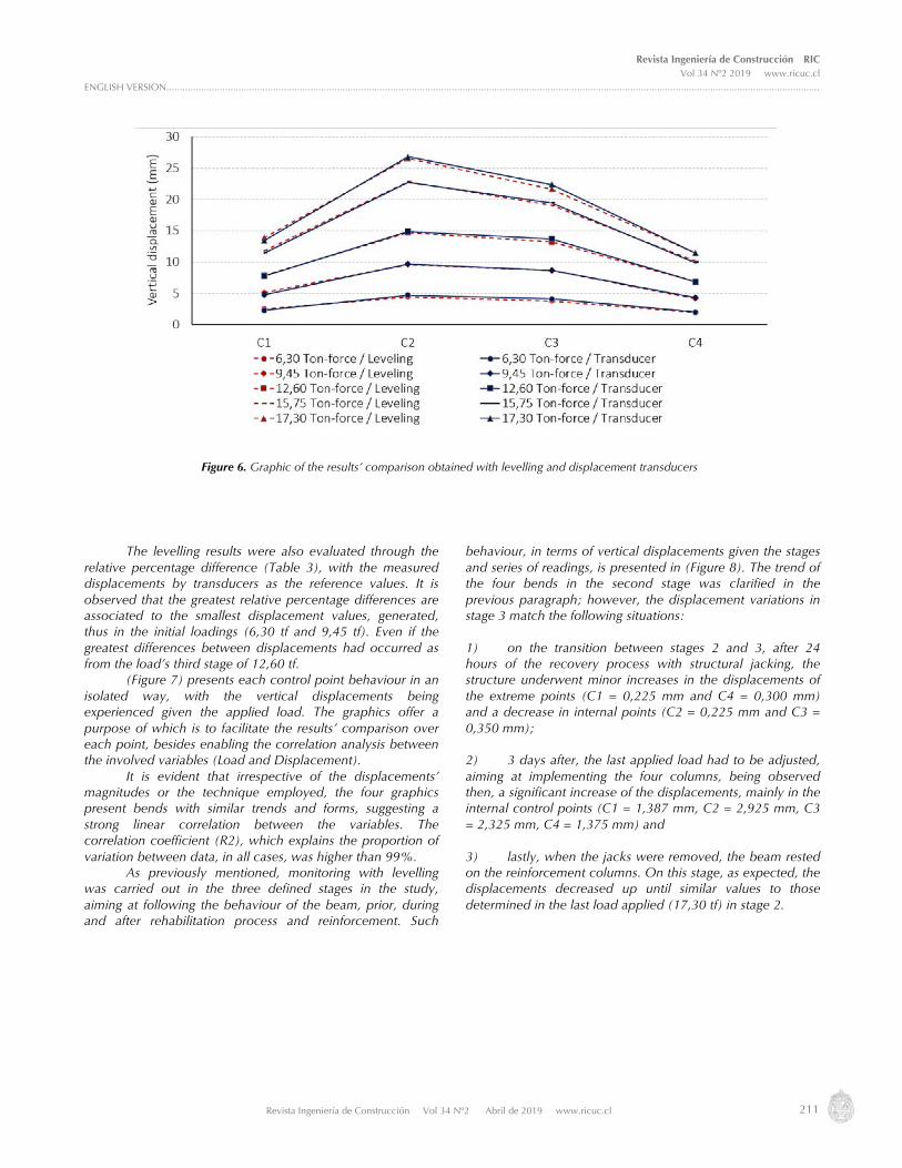
For result analyses purposes, the difference of the displacements obtained by the two techniques were calculated and are presented in (Table 3). Given the nature of the study and the techniques used, displacement differences are the product of the direct comparison between magnitudes measured by two different methods. In this respect it is important, however, that the levelling control points were located near transducers’ monitored points, however not exactly in the same places, a fact that partially explains the differences obtained. The greatest and smallest calculated standard deviation for the differences corresponds to point C3 (with a value of ±0,227 mm) and points C1 and C4 (with a value of ±0,128 mm) respectively. Standard deviations and relative percentage difference with similar order of magnitudes were reached in laboratory by other authors, for example, (Carvalho et al., 2001) (Gordon and Lichti, 2007) (Rönnholm et al., 2009) and (El-Ashmawy, 2017), using similar feature techniques and geodetic equipment. Following, figure 6 graphic shows the same differences, in addition to control points’ displacements, as in accordance with each technique, and a broad view of the deformations’ behaviour in a beam, given the load applied.
Table 2. Vertical displacements obtained through: (a) displacement transducers and (b) geometric levelling
Table 3. (a) Differences between vertical displacements and (b) relative percentage difference, obtained as from the comparison of the results of the two techniques applied
Revista Ingeniería de Construcción RIC Vol 34 Nº2 2019 www.ricuc.cl
ENGLISH VERSION.....................................................................................................................................................................................................................................................
Revista Ingeniería de Construcción Vol 34 Nº2 Abril de 2019 www.ricuc.cl 211
The levelling results were also evaluated through the relative percentage difference (Table 3), with the measured displacements by transducers as the reference values. It is observed that the greatest relative percentage differences are associated to the smallest displacement values, generated, thus in the initial loadings (6,30 tf and 9,45 tf). Even if the greatest differences between displacements had occurred as from the load’s third stage of 12,60 tf.
(Figure 7) presents each control point behaviour in an isolated way, with the vertical displacements being experienced given the applied load. The graphics offer a purpose of which is to facilitate the results’ comparison over each point, besides enabling the correlation analysis between the involved variables (Load and Displacement).
It is evident that irrespective of the displacements’ magnitudes or the technique employed, the four graphics present bends with similar trends and forms, suggesting a strong linear correlation between the variables. The correlation coefficient (R2), which explains the proportion of variation between data, in all cases, was higher than 99%.
As previously mentioned, monitoring with levelling was carried out in the three defined stages in the study, aiming at following the behaviour of the beam, prior, during and after rehabilitation process and reinforcement. Such
behaviour, in terms of vertical displacements given the stages and series of readings, is presented in (Figure 8). The trend of the four bends in the second stage was clarified in the previous paragraph; however, the displacement variations in stage 3 match the following situations:
1) on the transition between stages 2 and 3, after 24 hours of the recovery process with structural jacking, the structure underwent minor increases in the displacements of the extreme points (C1 = 0,225 mm and C4 = 0,300 mm) and a decrease in internal points (C2 = 0,225 mm and C3 = 0,350 mm); 2) 3 days after, the last applied load had to be adjusted, aiming at implementing the four columns, being observed then, a significant increase of the displacements, mainly in the internal control points (C1 = 1,387 mm, C2 = 2,925 mm, C3 = 2,325 mm, C4 = 1,375 mm) and 3) lastly, when the jacks were removed, the beam rested on the reinforcement columns. On this stage, as expected, the displacements decreased up until similar values to those determined in the last load applied (17,30 tf) in stage 2.
Figure 6. Graphic of the results’ comparison obtained with levelling and displacement transducers

212 Revista Ingeniería de Construcción Vol 34 Nº2 Abril de 2019 www.ricuc.cl
Figure 7. Vertical displacement given the applied load for each control point, using of the two monitoring techniques
Figure 8. Displacement behaviour bends in each monitored point during the three Stages, using precision geometric levelling

Revista Ingeniería de Construcción RIC Vol 34 Nº2 2019 www.ricuc.cl
ENGLISH VERSION.....................................................................................................................................................................................................................................................
Revista Ingeniería de Construcción Vol 34 Nº2 Abril de 2019 www.ricuc.cl 213
4. Conclusions
Based upon the comparison of procedures and the attained results by the two employed technique in this study, it is confirmed the usefulness of precision geometric levelling in control and monitoring of vertical displacements in structural elements subjected to recovery works and reinforcement. This is therefore a reliable and precise technique mainly due to its well defined office and field procedures, strict protocols in taking, collecting and processing data, as well as the employment of high precision equipment. Hence, precision geometric levelling is a valid alternative to be implemented jointly with structural instrumentation techniques, especially where redundancy needs to be obtained in the observations, data collection or in the monitoring of points in places where instrumentation with devices (sensors) is not accessible.
Although geometric levelling is not considered a modern technique in the structures monitoring, it is cost-effective feasible, accurate, and highly precise (as previously
mentioned), with acceptable uncertainties and results, considering procedures normally followed in the processes of recovery and reinforcement related to this type of works.
Some significant differences between levelling and structural instrumentation are related with the assembling time and installation of the equipment. The work’s preparation which involves placing displacement transducers requires a laborious installation and de-installation. The use of geometric levelling requires a qualified team for equipment handling and previous calculations.
With levelling there is the possibility of monitoring the behaviour of the structure post recovery (medium and long-term) not having to expose devices, which in the instrumentation case are very costly, in addition to the high risks of damaging sensors, given the collapse of the structure. The instrumentation technique commonly presents scarce or no redundancy in data, being limited to measure variations only on the subjected to monitoring point, not being possible to establish a correlation between points.
5. References Acosta E., Lacy M., Ramos M., Cano J., Herrera A., Avíles M., Gil A. (2018), Displacements Study of an Earth Fill Dam Based on High Precision
Geodetic Monitoring and Numerical Modeling. Sensors. 18(5), 1369: 1-15. https://doi.org/10.3390/s18051369. Ata E., HoŞbaŞ R., Pirti A. (2018), Monitoring the Structural Deformation of Davutpasa Barrack by Using Geodetic Methods. Technical Gezette.
25(3): 944–947. https://doi.org/10.17559/TV-20150219031334. Bannister A., Raymond S., Baker R. (1998), Surveying. Harlow, Essex, England: Addison Wesley Longman Ltd. Baroni H. (2003), Avaliação do comportamento dos deslocamentos transversais ao longo do tempo em vigas de concreto armado não
convencional. Dissertation. Porto Alegre, Universidade Federal do Rio Grande do Sul. Beshr A. (2015), Structural deformation monitoring and analysis of highway bridge using accurate geodetic techniques. Engineering. 7(8): 488–
498. http://dx.doi.org/10.4236/eng.2015.78045. Capra A., Bertacchini E., Castagnetti C., Rivola R., Dubbini M. (2015), Recent approaches in geodesy and geomatics for structures monitoring.
Rendiconti Lincei. 26(1): S53–S61. doi: 10.1007/s12210-015-0436-z. Carvalho R., Lopes S., Françoso M. (2001), Utilização de equipamentos de topografia para controle de deformação de estruturas. In: XX
Congresso Brasileiro de Cartografia, Porto Alegre, pp. 1-6, CD-ROM. Costantino D., Angelini M. (2014), Structural Monitoring with Geodetic Survey of Quadrifoglio Condominium (LECCE). Int. Arch. Photogramm.
Remote Sens. Spatial Inf. Sci. XL-5/W3: 179–187. doi: 10.5194/isprsarchives-XL-5-W3-179-2013. Detchev I., Habib A., El-Badry M. (2011), Estimation of vertical deflections in concrete beams through digital close range photogrammetry. In:
The ISPRS Remote Sensing and Spatial Information Sciences, Calgary, Canada, pp. 219-224. Díaz E., Robles P., Tomás R. (2018), Multitechnical approach for damage assessment and reinforcement of buildings located on subsiding areas:
Study case of a 7-story RC building in Murcia (SE Spain). Engineering Structures. 173: 744–757. https://doi.org/10.1016/j.engstruct.2018.07.031.
El-Ashmawy K. (2017), Developing and testing a method for deformations measurements of structures. Geodesy and Cartography. 43(1): 35–40. https://doi.org/10.3846/20296991.2017.1305545.
Erol B. (2010), Evaluation of High-Precision Sensors in Structural Monitoring. Sensors. 10(12): 10803–10827. https://doi.org/10.3390/s101210803.
Gordon S., Lichti D. (2007), Modeling Terrestrial Laser Scanner Data for Precise Structural Deformation Measurement. Journal of Surveying Engineering. 133(2): 72–80. https://doi.org/10.1061/(ASCE)0733-9453(2007)133:2(72).
Henriques M.J., Casaca J.M. (2001), Monitoring vertical displacements by means of geometric levelling. In: PB Lourenço & P Roca (eds.), Proceedings of the 3rd International Seminar on Historical Constructions, Universidade do Minho, Guimarães, Portugal, pp. 403-412.
Kovačič B., Motoh T. (2019), Determination of static and dynamic response of structures with geodetic methods in loading tests. Acta Geodaetica et Geophysica. https://doi.org/10.1007/s40328-019-00251-x.
Lienhart W. (2017), Geotechnical monitoring using total stations and laser scanners: critical aspects and solutions. Journal of Civil Structural Health Monitoring. 7(3): 315–324. doi: 10.1007/s13349-017-0228-5.
Lienhart W., Ehrhart M., Grick M. (2017), High frequent total station measurements for the monitoring of bridge vibrations. Journal of applied geodesy. 11(1): 1–8. https://doi.org/10.1515/jag-2016-0028.
Mascort-Albea E., Jaramillo-Morilla A., Ruiz-Jaramillo J. (2016), Proposed methodology for measurement, survey and assessment of vertical deformation of structures. Structural Survey. 34(3): 276–296. https://doi.org/10.1108/SS-02-2016-0006.

214 Revista Ingeniería de Construcción Vol 34 Nº2 Abril de 2019 www.ricuc.cl
Mill T., Ellmann A., Kiisa M., Idnurm J., Idnurm S., Horemuz M., Aavik A. (2015), Geodetic monitoring of bridge deformations occurring during static load testing. The Baltic Journal of Road and Bridge Engineering. 10 (1): 17–27. http://dx.doi.org/10.3846/bjrbe.2015.03.
Mills J., Barber D. (2004), Geomatics Techniques for Structural Surveying. Journal of Surveying Engineering. 130(2): 56–64. https://doi.org/10.1061/(ASCE)0733-9453(2004)130:2(56).
Mrówczynska M., Grochowska E., Gibowski S. (2018), Monitoring vertical displacements of an engineering object with masonry walls. Journal of Civil Engineering, Environment and Architecture. z.65(1/18): 53-62. doi:10.7862/rb.2018.6.
Mulahusić A., Topoljak J., Tuno N., Ademović N., Vojniković E. (2018), Analysis of leveling network of viaduct Koševo. e-Zbornik: Electronic Collection of Papers of the Faculty of Civil Engineering.8(15): 40-50. https://hrcak.srce.hr/203802; orcid.org/0000-0003-3099-8265.
Okiemute E., Ono M., Oduyebo O. (2018), Monitoring and Analysis of Vertical and Horizontal Deformations of a Large Structure Using Conventional Geodetic Journal of Environment and Earth Science. 8(12): 52-61. https://ssrn.com/abstract=3308857.
Palazzo D., Santos Filho M., Moreira A. (2005), A utilização de técnicas geodésicas no monitoramento de estruturas pré-moldadas. In: Encontro Nacional de Pesquisa Projeto Produção em Concreto Pré-moldado, São Carlos (SP), 03-04 November.
Reis L. (2001), Sobre a recuperação e reforço de estruturas de concreto armado. Dissertation. Belo Horizonte, Universidade Federal de Minas Gerais.
Rönnholm P., Nuikka M., Suominen A., Salo P., Hyyppä H., Pöntinen P., Haggrén H., Vermeer M., Puttonen J., Hirsi H., Kukko A., Kaartinen H., Hyyppä J., Jaakkola A. (2009), Comparison of measurement techniques and static theory applied to concrete beam deformation. The Photogrammetric Record. 24 (128): 351–371. https://doi.org/10.1111/j.1477-9730.2009.00548.x.
Sabuncu A., Ozener H. (2014), Monitoring vertical displacements by precise levelling: a case study along the Tuzla Fault, Izmir, Turkey. Geomatics, Natural Hazards and Risk. 5(4): 320–333. http://dx.doi.org/10.1080/19475705.2013.810179.
Silva I., Segantine P. (2015), Topografia para engenharia: teoria e prática de geomática. Rio de Janeiro: Elsevier. Souza V., Ripper T. (1998), Patologia, recuperação e reforço de estruturas de concreto. São Paulo: Pini. Tang Y., Kujawski E., Sztubecki J. (2018), Improved Leveling Approach and Its Application in Civil Engineering. Journal of Surveying
Engineering. 144(4): 06018002-1/06018002-9. https://doi.org/10.1061/(ASCE)SU.1943-5428.0000264.