displaying and annotating pipe networks
TRANSCRIPT

ChAPtER 16
Displaying and Annotating Pipe NetworksAs you have learned with other types of design that I have discussed to this point, simply designing an object or a system isn’t the end of the story. Your ability to share important information about the design is as important as the design itself. After all, without the effective sharing of information, the design can’t be properly reviewed or constructed. Pipe network design is no different, and it relies heavily on graphical appearance and annotation to convey design information.
In this chapter, you’ll study the use of pipe, structure, fitting, and appur-tenance styles to control the appearance of pipe networks in plan and pro-file view. You’ll also learn about annotating pipe networks using labels and tables. In a more general sense, you’ll learn how to combine all these fea-tures to effectively communicate the intent of your design to others.
In the previous two chapters, gravity and pressure networks were pre-sented separately because they each require a unique approach for layout and design. The stylization and annotation of gravity and pressure networks are virtually the same, however, with the only exception being the differ-ence between fitting styles and structure styles. For this reason, most of the information in this chapter doesn’t need to be duplicated for both types of networks as it was in the previous chapters.
in this chapter, you’ll learn to:
▶▶ display pipe networks using styles
▶▶ Annotate pipe networks in plan view
▶▶ Annotate pipe networks in profile view
▶▶ Create pipe network tables
Chappell, Eric. AutoCAD Civil 3D 2016 Essentials : Autodesk Official Press, John Wiley & Sons, Incorporated, 2015. ProQuest Ebook Central, http://ebookcentral.proquest.com/lib/osu/detail.action?docID=2052358.Created from osu on 2017-09-26 11:13:41.
Cop
yrig
ht ©
201
5. J
ohn
Wile
y &
Son
s, In
corp
orat
ed. A
ll rig
hts
rese
rved
.

3 1 8 C h ap t e r 16 • D i s p l a y i n g a n d A nno t a t i n g P i p e N e t wo r k s
Displaying Pipe Networks using StylesPipe and structure styles are two of the most sophisticated styles in the AutoCAD® Civil 3D® software. They provide many options for displaying the components of your pipe network design in plan, profile, model (3D), and even section view. It’s important to have many options for displaying pipe networks because often you have different types of systems in the same drawing that need to be differentiated graphically.
Applying Structure, Fitting, and Appurtenance StylesCivil 3D styles provide a number of fundamental ways to display structures, fit-tings, and appurtenances. In plan view, you can display a structure as an outline of its 3D form, or you can use an AutoCAD® block as a symbol representing the structure. When you use a block, you can determine its size according to the drawing scale, a fixed scale, or the actual dimensions of the part. Figure 16.1 shows a structure represented using an AutoCAD block on the left and as an outline of its 3D shape on the right.
AutoCAD Block Outline of 3D Shape
F i G u R E 1 6 . 1 A structure shown as a block (left) and as an outline of a 3D shape (right)
There are three ways to display a structure in profile view (Figure 16.2).
Solid The structure is shown as a slice through the 3D model of the part, which means the size, shape, and dimensions are an accurate representation (see Figure 16.2, left). Any detail within the interior of the part is visible with this option.
Boundary An outline of the 3D model of the part is shown (see Figure 16.2, center). This is also an accurate representation of the part but without the interior detail.
CertificationObjective
Chappell, Eric. AutoCAD Civil 3D 2016 Essentials : Autodesk Official Press, John Wiley & Sons, Incorporated, 2015. ProQuest Ebook Central, http://ebookcentral.proquest.com/lib/osu/detail.action?docID=2052358.Created from osu on 2017-09-26 11:13:41.
Cop
yrig
ht ©
201
5. J
ohn
Wile
y &
Son
s, In
corp
orat
ed. A
ll rig
hts
rese
rved
.

D i s p l a y i n g P i p e N e t wo r k s U s i n g S t y l e s 3 1 9
Block A block (see Figure 16.2, right) is inserted and sized based on one of sev-eral options. The most common option is to scale the block vertically to match the height of the part and horizontally to match the width of the part. A block can provide the desired appearance of the part, but because of the horizontal and vertical scaling, it may not be an exact dimensional match to the actual part.
F i G u R E 1 6 . 2 A structure shown as a solid (left), boundary (center), and block (right)
There are three ways to display fittings and appurtenances (Figure 16.3).
F i G u R E 1 6 . 3 A tee fitting shown as a centerline (left), catalog defined block (center), and user-defined block (right)
Centerline The Centerline option (see Figure 16.3, left) is the simplest choice and represents the fitting or appurtenance as a single line.
Catalog Defined Block The Catalog Defined Block option (see Figure 16.3, center) is the true 3D form of the fitting or appurtenance shown in plan view.
user Defined Block The User Defined Block (see Figure 16.3, right) option allows you to use any AutoCAD block to represent the fitting or appurtenance.
Chappell, Eric. AutoCAD Civil 3D 2016 Essentials : Autodesk Official Press, John Wiley & Sons, Incorporated, 2015. ProQuest Ebook Central, http://ebookcentral.proquest.com/lib/osu/detail.action?docID=2052358.Created from osu on 2017-09-26 11:13:41.
Cop
yrig
ht ©
201
5. J
ohn
Wile
y &
Son
s, In
corp
orat
ed. A
ll rig
hts
rese
rved
.

3 2 0 C h ap t e r 16 • D i s p l a y i n g a n d A nno t a t i n g P i p e N e t wo r k s
In profile view, there are no options for the display of fittings and appurte-nances; fittings are simply represented as an outline, and appurtenances are represented by a symbol that resembles their type.
As a designer, it isn’t likely that you’ll be responsible for configuring styles or having to choose which display configuration to use—these things are typically taken care of by a CAD manager. However, knowing the ways in which struc-tures, fittings, and appurtenances can be displayed will be helpful when you’re asking your CAD manager to build some styles for you.
Exercise 16.1: Control the Display of StructuresIn this exercise, you’ll assign different styles to gravity and pressure structures to change their appearance. You’ll observe the changes made to the appearance of those structures and see how they can potentially affect your design.
1. Open the drawing named Applying Structure and Fitting Styles.dwg located in the Chapter 16 class data folder.
2. In the left viewport, click the sanitary manhole (the one with the S inside the circle), and then click Structure Properties on the ribbon.
This opens the Structure Properties dialog box.
3. Click the Information tab, and then select C-SSWR – Outline as the style. Click OK.
This style shows the outline of the actual 3D part, which reveals that the manhole is actually much larger than the symbol suggests.
4. Press Esc to clear the selection of the sanitary manhole. Click the storm manhole (the one with the D inside the circle), and then select Structure Properties on the ribbon.
5. Change the style of this manhole to C-STRM – Outline. Click OK to dismiss the Structure Properties dialog. Press Esc to clear the selection.
With both manholes shown at their actual size, there is an obvious conflict (see Figure 16.4). Next you’ll use styles to change the appear-ance of some pressure network structures.
6. In the left viewport, pan northward to the beginning of Jordan Court where the new water line ties to the existing water line. Click the tee fitting and the two elbow fittings near the connection point.
7. Right-click, and select Properties. Change the Style property to Water 3D.
If you haven’t already done so, download and install the files for Chapter 16 according to the instructions in this book’s Introduction.
▶
▶
In the left view, the drawing is zoomed in to two manholes that are in close proxim-ity to one another but don’t appear to be conflicting. In the lower-right view, it appears there could be a conflict, but at the current view angle, it isn’t absolutely certain.
▶
D is for drainage, a term that is often considered interchangeable with stormwater.
▶
In plan view, the fit-tings now appear in their true 3D form as a result of the style change.
Chappell, Eric. AutoCAD Civil 3D 2016 Essentials : Autodesk Official Press, John Wiley & Sons, Incorporated, 2015. ProQuest Ebook Central, http://ebookcentral.proquest.com/lib/osu/detail.action?docID=2052358.Created from osu on 2017-09-26 11:13:41.
Cop
yrig
ht ©
201
5. J
ohn
Wile
y &
Son
s, In
corp
orat
ed. A
ll rig
hts
rese
rved
.

D i s p l a y i n g P i p e N e t wo r k s U s i n g S t y l e s 3 2 1
Con�ict
F i G u R E 1 6 . 4 A conflict between two manholes is evident when the style reflects their true size.
8. Press Esc to clear the previous selection but keep the Properties win-dow open. Pan northeast to the other corner of the Jordan Court – Emerson Road intersection, and select the storm manhole there.
it’s Not Called 3D for Nothing
The true form of a Civil 3D pipe or structure is a 3D object. For example, a manhole structure is typically some form of cylinder and is often somewhat complex, including tapers, eccentric cylinders, and so on. Some of the ways in which structures can be displayed involve slicing through this shape or showing an outline of it. In the following image, the same structure is shown from a 3D perspective (left), in plan view as an outline (center), and in profile view as a slice through the part (right). By using 3D representations of structures in your drawings, you can design more accurately and ensure that your structures aren’t conflicting with other underground objects.
Chappell, Eric. AutoCAD Civil 3D 2016 Essentials : Autodesk Official Press, John Wiley & Sons, Incorporated, 2015. ProQuest Ebook Central, http://ebookcentral.proquest.com/lib/osu/detail.action?docID=2052358.Created from osu on 2017-09-26 11:13:41.
Cop
yrig
ht ©
201
5. J
ohn
Wile
y &
Son
s, In
corp
orat
ed. A
ll rig
hts
rese
rved
.

3 2 2 C h ap t e r 16 • D i s p l a y i n g a n d A nno t a t i n g P i p e N e t wo r k s
9. In the Properties window, change the style to C-STRM – MH Symbol Plan & Profile.
As you select the new style, watch the manhole in the profile view in the top-right viewport to see its shape change slightly. This is because the block isn’t an accurate dimensional representation of the manhole.
10. Save and close the drawing.
You can view the results of successfully completing this exercise by opening Applying Structure and Fitting Styles - Complete.dwg.
Applying Pipe StylesA pipe object is a bit simpler than a structure object in that it’s essentially the extrusion of a circle, an ellipse, or a rectangle. Even so, the graphical represen-tation of a pipe is broken down into numerous parts, each of which can be styl-ized differently. Figure 16.5 shows a pipe and its components in profile view.
Pipe HatchPipe Centerline
Inside Pipe Walls Outside Pipe Walls
F i G u R E 1 6 . 5 A pipe in profile view
You can use pipe styles to control the various pipe components as follows:
Pipe Centerline In addition to controlling the visibility and graphical proper-ties of the pipe centerline, such as layer, color, and linetype, you can also control the width of the centerline in several ways, including setting it to match the diameter of the pipe. The striped appearance of the storm pipes you have seen in the example drawings was achieved by setting the centerline width to the inside pipe diameter and using a dashed linetype.
▶
This may be acceptable for some instances, but when you need to see the exact dimensions of a manhole, you would use a different style.
Chappell, Eric. AutoCAD Civil 3D 2016 Essentials : Autodesk Official Press, John Wiley & Sons, Incorporated, 2015. ProQuest Ebook Central, http://ebookcentral.proquest.com/lib/osu/detail.action?docID=2052358.Created from osu on 2017-09-26 11:13:41.
Cop
yrig
ht ©
201
5. J
ohn
Wile
y &
Son
s, In
corp
orat
ed. A
ll rig
hts
rese
rved
.
D i s p l a y i n g P i p e N e t wo r k s U s i n g S t y l e s 3 2 3
inside and outside Pipe Walls You can use styles to control the visibility and graphical properties of the inner and outer walls.
Pipe End line This is a line drawn across either end of the pipe. The style can determine whether this line is drawn to the outer pipe wall or inner pipe wall.
Pipe hatch You can use a pipe style to hatch a pipe across its inside or outside diameter or in the area between the inner and outer walls. The pattern, scale, and rotation of the hatch can be specified as part of the style.
Crossing Pipe You can use a pipe style to show a pipe as though it’s cross-ing through the profile view rather than oriented parallel to it. This typically takes the form of an ellipse, either because of vertical exaggeration or because the pipe crosses through at an angle. This is extremely useful for ensuring that crossing pipes don’t conflict with one another. In profile view, you can control the visibility and graphical properties of the crossing pipe components such as inside walls, outside walls, and hatching.
Again, you aren’t likely to be responsible for creating the styles that configure these different display options. However, if you have a basic understanding of what is possible, you can more accurately request the specific styles you need from your CAD manager.
Exercise 16.2: Control the Display of PipesIn this exercise, you’ll alter the appearance of two pipes by changing their style assignment. In one case, this change will be apparent in plan view, and in the other it will be shown in profile view.
1. Open the drawing named Applying Pipe Styles.dwg located in the Chapter 16 class data folder.
In this drawing, the left view is zoomed in to Logan Court where a sanitary pipe crosses a storm pipe, and the same pipes are shown in profile view on the top right and 3D view on the bottom right.
2. In the left view, click the green pipe labeled SAN. Click Pipe Properties on the ribbon.
3. In the Pipe Properties dialog box, click the Information tab. Change the style to C-SSWR – Double Line, and click OK.
If you haven’t already done so, download and install the files for Chapter 16 according to the instructions in this book’s Introduction.
◀
The appearance of the pipe changes in the plan view. The SAN label has been turned off, and the pipe is now shown as a double line representing the inside diameter.
◀
Chappell, Eric. AutoCAD Civil 3D 2016 Essentials : Autodesk Official Press, John Wiley & Sons, Incorporated, 2015. ProQuest Ebook Central, http://ebookcentral.proquest.com/lib/osu/detail.action?docID=2052358.Created from osu on 2017-09-26 11:13:41.
Cop
yrig
ht ©
201
5. J
ohn
Wile
y &
Son
s, In
corp
orat
ed. A
ll rig
hts
rese
rved
.
3 2 4 C h ap t e r 16 • D i s p l a y i n g a n d A nno t a t i n g P i p e N e t wo r k s
4. Press Esc to clear the previous selection, and then click the profile view grid in the top-right viewport. Click Profile View Properties on the ribbon.
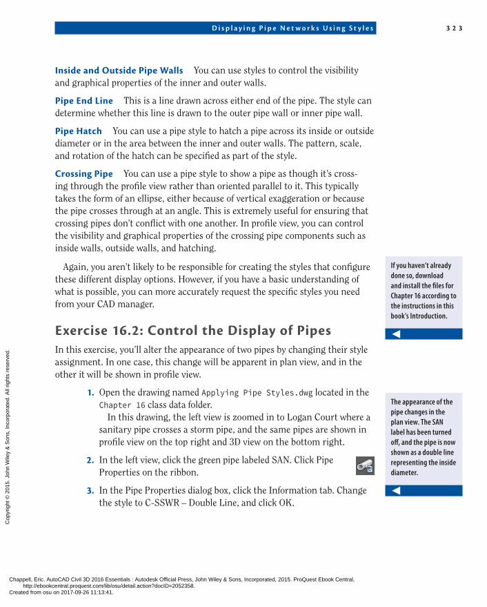
5. In the Profile View Properties dialog box, click the Pipe Networks tab. Scroll, and locate the pipes listed beneath the Storm2 network. One of the pipes is set to Yes in the Draw column. Check the box in the Style Override column for this pipe.
6. In the Pick Pipe Style dialog box, select C-PROF-STRM – Crossing and click OK. Click OK once more to dismiss the Profile View Properties dialog box.
You’re returned to the drawing, and the storm pipe is now repre-sented as an ellipse. The ellipse is placed at the location where the storm pipe crosses the alignment (see Figure 16.6).
Storm Pipe Crossing
F i G u R E 1 6 . 6 A storm pipe crossing shown as an ellipse indicates a conflict with a sanitary pipe.
7. Save and close the drawing.
You can view the results of successfully completing this exercise by opening Applying Pipe Styles - Complete.dwg.
▶
When you view the storm and sanitary pipes this way, you can clearly see that there is a conflict and that you need to change the design.
Chappell, Eric. AutoCAD Civil 3D 2016 Essentials : Autodesk Official Press, John Wiley & Sons, Incorporated, 2015. ProQuest Ebook Central, http://ebookcentral.proquest.com/lib/osu/detail.action?docID=2052358.Created from osu on 2017-09-26 11:13:41.
Cop
yrig
ht ©
201
5. J
ohn
Wile
y &
Son
s, In
corp
orat
ed. A
ll rig
hts
rese
rved
.

A nn o t a t i n g P i p e N e t wo r k s i n P l a n V i ew 3 2 5
Profile view overrides
The Profile View Properties dialog box has a special Pipe Networks tab that lists all the pipes and structures in the drawing. You can display any of them in a given profile view by simply checking a box in the Draw column. You can even perform a style override so that a pipe or structure can be displayed in a given profile view using a different style than the one assigned to it in the Pipe Properties dialog box. This is especially handy when you need to show a pipe using a crossing style in one profile view and using a “normal” style in another. The following image shows the Pipe Networks tab of the Profile View Properties dialog box.
Annotating Pipe Networks in Plan viewFor a pipe system to function properly, it must be installed with a considerable amount of accuracy. And for this to take place, detailed information must be conveyed to the contractor installing the pipes and structures in the field. The most common way to do this is to add text to your drawing. With stations and offsets, you provide the horizontal location of each structure, and with slopes and elevations, you dictate the depth of each pipe and the slope needed for water to flow through it properly. These values are typically expressed to the near-est hundredth of a foot or thousandth of a meter. It’s amazing to think that a trench can be excavated and a heavy concrete pipe laid in it with such accuracy, but it happens every day.
So far, you have worked with functions that create pipes and structures, edit their design, and control their graphical appearance in the drawing. In the fol-lowing sections, you’ll learn how to annotate your design, which is arguably
Chappell, Eric. AutoCAD Civil 3D 2016 Essentials : Autodesk Official Press, John Wiley & Sons, Incorporated, 2015. ProQuest Ebook Central, http://ebookcentral.proquest.com/lib/osu/detail.action?docID=2052358.Created from osu on 2017-09-26 11:13:41.
Cop
yrig
ht ©
201
5. J
ohn
Wile
y &
Son
s, In
corp
orat
ed. A
ll rig
hts
rese
rved
.

3 2 6 C h ap t e r 16 • D i s p l a y i n g a n d A nno t a t i n g P i p e N e t wo r k s
even more important than the design itself. The lines and symbols provide a useful picture of the design, but the stations, offsets, elevations, slopes, and so on provided by your annotations are used to make precise measurements that locate and orient each pipe and structure in the field.
Renaming Pipes and StructuresMany pipe network designs involve a large number of pipes and structures. For this reason, it’s good design practice to have a naming and/or numbering sys-tem that helps you keep track of these many components. Before labeling pipes and structures, you should spend some time renaming them according to the system you’ll use.
Exercise 16.3: Rename Pipes and StructuresIn this exercise, you’ll do some “bookkeeping” to rename the pipes and struc-tures in the Storm1 network according to a numerical sequence.
1. Open the drawing named Renaming Pipes and Structures.dwg located in the Chapter 16 class data folder.
2. In the viewport on the left, click the inlet at station 5+50 (0+170) that is on the east side of Jordan Court. Right-click, and select Properties.
3. In the Properties window, change the name to INLET-01. Press Esc to clear the selection, and then click the inlet across the street from INLET-01.
4. In the Properties window, change the name to INLET-02. Press Esc to clear the selection.
5. Click the pipe between INLET-01 and INLET-02, and change its name to STM-01.
6. Change the name of the pipe exiting INLET-02 to the north to STM-02.
7. Change the name of the manhole near station 3+50 (0+110) to STMH-01.
8. Continue working along the pipe network, renaming the inlets, pipes, and manholes according to this sequence. When you get to the final structure, the endwall, name it ENDWALL-01.
9. In Prospector, expand Pipe Networks ➢ Networks ➢ Storm1. Under Storm1, click Pipes.
▶
If you haven’t already done so, download and install the files for Chapter 16 according to the instructions in this book’s Introduction.
Chappell, Eric. AutoCAD Civil 3D 2016 Essentials : Autodesk Official Press, John Wiley & Sons, Incorporated, 2015. ProQuest Ebook Central, http://ebookcentral.proquest.com/lib/osu/detail.action?docID=2052358.Created from osu on 2017-09-26 11:13:41.
Cop
yrig
ht ©
201
5. J
ohn
Wile
y &
Son
s, In
corp
orat
ed. A
ll rig
hts
rese
rved
.

A nn o t a t i n g P i p e N e t wo r k s i n P l a n V i ew 3 2 7
In the item view at the bottom of Prospector, the pipe names should all be updated as shown in Figure 16.7, but they may appear in a different order.
F i G u R E 1 6 . 7 Revised pipe names shown in the item view of Prospector
10. Under Storm1, click Structures. In the item view at the bottom of Prospector, the values listed in
the Name column should match Figure 16.8.
Structure Names
F i G u R E 1 6 . 8 Revised structure names shown in the item view of Prospector
11. Save and close the drawing.
You can view the results of successfully completing this exercise by opening Renaming Pipes and Structures - Complete.dwg.
Chappell, Eric. AutoCAD Civil 3D 2016 Essentials : Autodesk Official Press, John Wiley & Sons, Incorporated, 2015. ProQuest Ebook Central, http://ebookcentral.proquest.com/lib/osu/detail.action?docID=2052358.Created from osu on 2017-09-26 11:13:41.
Cop
yrig
ht ©
201
5. J
ohn
Wile
y &
Son
s, In
corp
orat
ed. A
ll rig
hts
rese
rved
.

3 2 8 C h ap t e r 16 • D i s p l a y i n g a n d A nno t a t i n g P i p e N e t wo r k s
Creating labels in Plan viewTo create labels in plan view, you use the Add Labels command. You can create labels one by one or for all the parts of the network at once. After the labels are in place, you may have to drag them to clear areas in the drawing so that they can be read more easily.
Exercise 16.4: Create Plan view labelsIn this exercise, you’ll create all the plan view labels at once for the Storm1 net-work. The labels will be cluttered, but you’ll address that in the next exercise.
1. Open the drawing named Creating Labels in Plan View.dwg located in the Chapter 16 class data folder.
2. On the Annotate tab of the ribbon, click Add Labels.
3. In the Add Labels dialog box, do the following:
a. For Feature, select Pipe Network.
b. For Label Type, select Entire Network Plan.
c. For Pipe Label Style, select C-STRM – Pipe Data (One Line).
d. For Structure Label Style, select C-STRM – Structure Data.
e. Click Add.
4. Click any pipe or structure in the storm network near the entrance to Jordan Court.
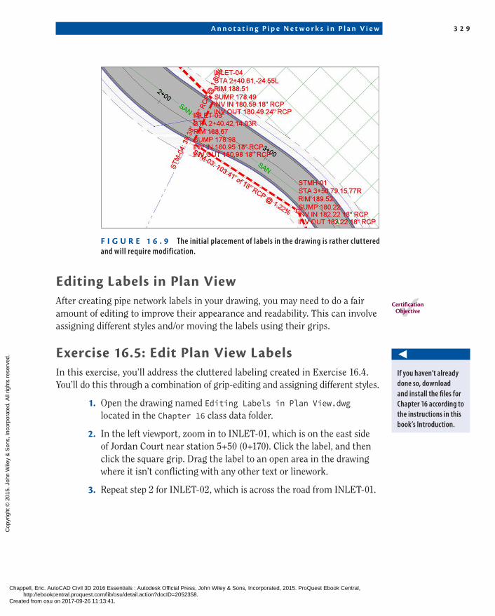
Labels are added on every pipe and structure in the network, which makes the drawing look cluttered (see Figure 16.9).
5. Save and close the drawing.
You can view the results of successfully completing this exercise by opening Creating Labels in Plan View - Complete.dwg.
▶
If you haven’t already done so, download and install the files for Chapter 16 according to the instructions in this book’s Introduction.
▶
This will be addressed in the next exercise.
Chappell, Eric. AutoCAD Civil 3D 2016 Essentials : Autodesk Official Press, John Wiley & Sons, Incorporated, 2015. ProQuest Ebook Central, http://ebookcentral.proquest.com/lib/osu/detail.action?docID=2052358.Created from osu on 2017-09-26 11:13:41.
Cop
yrig
ht ©
201
5. J
ohn
Wile
y &
Son
s, In
corp
orat
ed. A
ll rig
hts
rese
rved
.
A nn o t a t i n g P i p e N e t wo r k s i n P l a n V i ew 3 2 9
F i G u R E 1 6 . 9 The initial placement of labels in the drawing is rather cluttered and will require modification.
Editing labels in Plan viewAfter creating pipe network labels in your drawing, you may need to do a fair amount of editing to improve their appearance and readability. This can involve assigning different styles and/or moving the labels using their grips.
Exercise 16.5: Edit Plan view labelsIn this exercise, you’ll address the cluttered labeling created in Exercise 16.4. You’ll do this through a combination of grip-editing and assigning different styles.
1. Open the drawing named Editing Labels in Plan View.dwg located in the Chapter 16 class data folder.
2. In the left viewport, zoom in to INLET-01, which is on the east side of Jordan Court near station 5+50 (0+170). Click the label, and then click the square grip. Drag the label to an open area in the drawing where it isn’t conflicting with any other text or linework.
3. Repeat step 2 for INLET-02, which is across the road from INLET-01.
CertificationObjective
◀
If you haven’t already done so, download and install the files for Chapter 16 according to the instructions in this book’s Introduction.
Chappell, Eric. AutoCAD Civil 3D 2016 Essentials : Autodesk Official Press, John Wiley & Sons, Incorporated, 2015. ProQuest Ebook Central, http://ebookcentral.proquest.com/lib/osu/detail.action?docID=2052358.Created from osu on 2017-09-26 11:13:41.
Cop
yrig
ht ©
201
5. J
ohn
Wile
y &
Son
s, In
corp
orat
ed. A
ll rig
hts
rese
rved
.

3 3 0 C h ap t e r 16 • D i s p l a y i n g a n d A nno t a t i n g P i p e N e t wo r k s
4. Press Esc to clear the previous selection. Click the pipe label for STM-01 (the pipe that connects INLET-01 to INLET-02). Right-click, and select Properties.
5. In the Properties window, change the value for Pipe Label Style to C-STRM – Pipe Data (Stacked).
6. With the label still selected, click the square grip and drag it to a clear location in the drawing.
7. Use the square label grip to move the STMH-01, INLET-03, and INLET-04 labels to a clear location in the drawing.
8. Change the style for the STM-04 label to C-STRM – Pipe Data (Stacked) as you did in steps 4 and 5 for the STM-01 label. Drag it to a clear location in the drawing as you did the STM-01 label in step 6.
9. Press Esc to clear any label selections. Click the STM-05 label, and then click Flip Label on the ribbon.
10. With the STM-05 label still selected, click its diamond-shaped grip, and drag the label along the pipe to demonstrate the behavior of this grip.
11. Drag the remaining structure labels to clear areas in the draw-ing, and change the label style for STM-06 to C-STRM – Pipe Data (Stacked).
With all the edits to the labels complete, the annotation of the design is much clearer and more readable, as you can see if you com-pare Figure 16.10 to Figure 16.9.
12. Save and close the drawing.
You can view the results of successfully completing this exercise by opening Editing Labels in Plan View - Complete.dwg.
▶
This places the label on the east side of the pipe, where it’s much more readable.
Chappell, Eric. AutoCAD Civil 3D 2016 Essentials : Autodesk Official Press, John Wiley & Sons, Incorporated, 2015. ProQuest Ebook Central, http://ebookcentral.proquest.com/lib/osu/detail.action?docID=2052358.Created from osu on 2017-09-26 11:13:41.
Cop
yrig
ht ©
201
5. J
ohn
Wile
y &
Son
s, In
corp
orat
ed. A
ll rig
hts
rese
rved
.

A nn o t a t i n g P i p e N e t wo r k s i n P r o f i l e V i ew 3 3 1
F i G u R E 1 6 . 1 0 The same area shown in Figure 16.9 after edits have been made to the labels
Annotating Pipe Networks in Profile viewProfile view is just as important as plan view for illustrating the design and providing important textual and numerical information about it. For this rea-son, you’ll frequently have to provide profile labels in addition to plan labels. Often, you’ll duplicate the information shown in plan view, enabling the con-tractor or the reviewer of the drawing to have the information they need in both places, without having to flip back and forth between drawings.
You don’t need to rename the pipes and structures for the profile view if you have already done so in plan view. This is because the plan and profile versions of the pipe network are the same objects viewed from different perspectives. In other words, renaming a pipe in plan view automatically renames it in profile view because the two versions of the pipe represent a single object.
Creating labels in Profile viewOnce again, creating pipe network labels in profile view is done using the Add Labels dialog box. You can use either the Entire Network Profile option to label all the pipes and structures at once or the Single Part Profile option to label them one by one.
Chappell, Eric. AutoCAD Civil 3D 2016 Essentials : Autodesk Official Press, John Wiley & Sons, Incorporated, 2015. ProQuest Ebook Central, http://ebookcentral.proquest.com/lib/osu/detail.action?docID=2052358.Created from osu on 2017-09-26 11:13:41.
Cop
yrig
ht ©
201
5. J
ohn
Wile
y &
Son
s, In
corp
orat
ed. A
ll rig
hts
rese
rved
.

3 3 2 C h ap t e r 16 • D i s p l a y i n g a n d A nno t a t i n g P i p e N e t wo r k s
Exercise 16.6: Create Profile view labelsIn this exercise, you’ll create pipe and structure labels in profile view.
1. Open the drawing named Creating Labels in Profile View.dwg located in the Chapter 16 class data folder.
2. On the Annotate tab, click Add Labels.
3. In the Add Labels dialog box, do the following:
a. For Feature, select Pipe Network.
b. For Label Type, select Single Part Profile.
c. For Pipe Label Style, select C-PROF-STRM – Pipe Data.
d. For Structure Label Style, select C-PROF-STRM – Structure Data (Above).
e. Click Add.
Figure 16.11 shows the Add Labels dialog box with these settings.
F i G u R E 1 6 . 1 1 The Add Labels dialog box showing the styles selected for labeling pipes and structures in profile view
4. Click the first and last structures in the upper-right profile view.
▶
If you haven’t already done so, download and install the files for Chapter 16 according to the instructions in this book’s Introduction.
This creates labels that are oriented above these two structures. For the remaining two structures, the road profile label is in the way, so the structure labels will be placed below the structures.
▶
Chappell, Eric. AutoCAD Civil 3D 2016 Essentials : Autodesk Official Press, John Wiley & Sons, Incorporated, 2015. ProQuest Ebook Central, http://ebookcentral.proquest.com/lib/osu/detail.action?docID=2052358.Created from osu on 2017-09-26 11:13:41.
Cop
yrig
ht ©
201
5. J
ohn
Wile
y &
Son
s, In
corp
orat
ed. A
ll rig
hts
rese
rved
.

A nn o t a t i n g P i p e N e t wo r k s i n P r o f i l e V i ew 3 3 3
5. In the Add Labels dialog box, select C-PROF-STRM – Structure Data (Below) as the structure label style. Click Add.
6. Click the second and third structures. The labels are still placed above the structure, but notice that the
formatting is a bit different. You’ll reposition these structure labels in the next exercise.
7. Click the three pipes in the profile view to place a label above each one. The drawing should now look like Figure 16.12.
F i G u R E 1 6 . 1 2 The initial placement of pipe network labels in profile view
8. Save and close the drawing.
You can view the results of successfully completing this exercise by opening Creating Labels in Profile View - Complete.dwg.
Editing labels in Profile viewJust as in plan view, you’ll most likely have to change the initial placement and styles of your profile view labels in order to make them easier to read. As you did before, you can assign different styles to change formatting, and you can use grips to move the labels. For some label styles, you have an extra grip located at the dimension anchor. The dimension anchor is a floating point that can only be moved vertically. This can be useful because you often need to move a label up or down to improve readability while maintaining its horizontal position on the pro-file view. Additional dimension anchor settings enable you to position a label based on the location of a part or the profile view grid. Simply put, the dimension anchor gives you more options and more flexibility for label placement in profile view.
CertificationObjective
Chappell, Eric. AutoCAD Civil 3D 2016 Essentials : Autodesk Official Press, John Wiley & Sons, Incorporated, 2015. ProQuest Ebook Central, http://ebookcentral.proquest.com/lib/osu/detail.action?docID=2052358.Created from osu on 2017-09-26 11:13:41.
Cop
yrig
ht ©
201
5. J
ohn
Wile
y &
Son
s, In
corp
orat
ed. A
ll rig
hts
rese
rved
.

3 3 4 C h ap t e r 16 • D i s p l a y i n g a n d A nno t a t i n g P i p e N e t wo r k s
Exercise 16.7: Edit Profile view labelsIn this exercise, you’ll edit the labels that were created in the previous exercise to improve their appearance and readability.
1. Open the drawing named Editing Labels in Profile View.dwg located in the Chapter 16 class data folder.
2. In the upper-right viewport, click the first structure label (STMH-02), and then click the square grip at the top of the label and drag it upward to a clear area in the drawing.
3. Press Esc to clear the previous selection. Click the second structure label (INLET-04), and then click Label Properties on the ribbon.
4. In the Properties window, change Dimension Anchor Option to Below. The label flips to a downward position but is still overlapping the structure.
5. Click the square grip at the top of the label. Then click the Ortho Mode button at the bottom of your screen, and move the label down-ward until the end of the line is at the bottom of the structure.
6. Repeat steps 3–5 for the third structure label (INLET-05). With the label edits you have made, the annotation of the pipe
network in profile view has been greatly improved. Compare the result in Figure 16.13 with the initial placement of the labels in Figure 16.12.
F i G u R E 1 6 . 1 3 Pipe network labels in profile view that have been edited to improve readability
▶
If you haven’t already done so, download and install the files for Chapter 16 according to the instructions in this book’s Introduction.
▶
Note that this grip is constrained to up and down movements. This is because the grip is located at the dimen-sion anchor.
▶
Ortho mode restricts the movement of your cursor to up, down, left, and right. This will help you keep the label aligned with the structure as you move it down.
Chappell, Eric. AutoCAD Civil 3D 2016 Essentials : Autodesk Official Press, John Wiley & Sons, Incorporated, 2015. ProQuest Ebook Central, http://ebookcentral.proquest.com/lib/osu/detail.action?docID=2052358.Created from osu on 2017-09-26 11:13:41.
Cop
yrig
ht ©
201
5. J
ohn
Wile
y &
Son
s, In
corp
orat
ed. A
ll rig
hts
rese
rved
.
C r e a t i n g p i p e n e t w o r k ta b l e s 3 3 5
7. Save and close the drawing.
You can view the results of successfully completing this exercise by opening Editing Labels in Profile View - Complete.dwg.
Creating Pipe Network tablesAs you have learned in previous chapters, tables are an effective way to convey information about a design. The main advantage of tables is that they organize the information in an orderly fashion, making it easy to read. The disadvantage is that the reader has two places to look for information: the main drawing for the graphical representation of the design and the table for the numerical and textual information. For this reason, tables are typically used if the main draw-ing would be too cluttered or difficult to read if the textual and numerical infor-mation were included in it.
In previous chapters, you created tables for parcels and alignments. One fun-damental difference when working with pipe network tables is that they don’t need to reference labels in the drawing. For parcels and alignments, you had to create tag labels and then create the tables by selecting those labels. For a pipe network, the table references the pipes and structures directly, so no tag labels are required. However, it’s good practice to provide labels in the drawing that identify each pipe and structure so the reader of the drawing can see how they relate to the table.
Exercise 16.8: Create a Pipe Network tableIn this exercise, you’ll create a pipe network table and then create a series of labels in the drawing that will correlate the drawing objects with the table. You’ll edit these labels so that they are clear and legible.
1. Open the drawing named Creating Pipe Network Tables.dwg located in the Chapter 16 class data folder.
2. On the Annotate tab of the ribbon, click Add Tables ➢ Pipe Network ➢ Add Structure. This opens the Structure Table Creation dialog box.
3. For Table Style, select C-SSWR – Structure & Pipe Data.
4. Verify that By Network is selected and that Sanitary is chosen under Select Network. Click OK.
If you haven’t already done so, download and install the files for Chapter 16 according to the instructions in this book’s Introduction.
◀
With these settings, all the pipes and struc-tures in the sanitary pipe network will be included in the table. There is also a Multiple Selection option, which enables you to handpick the items you want represented in the table.
◀
Chappell, Eric. AutoCAD Civil 3D 2016 Essentials : Autodesk Official Press, John Wiley & Sons, Incorporated, 2015. ProQuest Ebook Central, http://ebookcentral.proquest.com/lib/osu/detail.action?docID=2052358.Created from osu on 2017-09-26 11:13:41.
Cop
yrig
ht ©
201
5. J
ohn
Wile
y &
Son
s, In
corp
orat
ed. A
ll rig
hts
rese
rved
.

3 3 6 C h ap t e r 16 • D i s p l a y i n g a n d A nno t a t i n g P i p e N e t wo r k s
5. Pick a point in the left viewport in some open space. The table is inserted into the drawing. Zoom in, and study the
information shown in the table (see Figure 16.14).
F i G u R E 1 6 . 1 4 A portion of a structure table created for a sanitary sewer pipe network
6. On the Annotate tab of the ribbon, click Add Labels.
7. In the Add Labels dialog box, do the following:
a. For Feature, select Pipe Network.
b. For Label Type, select Entire Network Plan.
c. For Pipe Label Style, select C-SSWR – Name Only.
d. For Structure Label Style, select C-SSWR – Name Only.
e. Click Add.
8. Click any sanitary pipe or structure in the drawing.
9. For each sanitary sewer manhole, click the label and then use the square grip to drag the label into a clear location of the drawing.
▶
The entire network is labeled with the name of each pipe and structure.
Chappell, Eric. AutoCAD Civil 3D 2016 Essentials : Autodesk Official Press, John Wiley & Sons, Incorporated, 2015. ProQuest Ebook Central, http://ebookcentral.proquest.com/lib/osu/detail.action?docID=2052358.Created from osu on 2017-09-26 11:13:41.
Cop
yrig
ht ©
201
5. J
ohn
Wile
y &
Son
s, In
corp
orat
ed. A
ll rig
hts
rese
rved
.

C r e a t i n g p i p e n e t w o r k ta b l e s 3 3 7 n o w Yo u K n o w 3 3 7
10. For each sanitary sewer pipe label, click the label and use its diamond-shaped grip to slide it to a location that is clear of other text or linework. If that isn’t possible, use the square grip to drag it to a clear area in the drawing.
11. Save and close the drawing.
You can view the results of successfully completing this exercise by opening Creating Pipe Network Tables - Complete.dwg.
Now You Know
Now that you have completed this chapter, you’re able to change the appearance of struc-tures and pipes by assigning different styles to them. You have learned the importance of good bookkeeping when working with pipe networks, and you know how to rename pipes and structures according to a logical labeling system. You can also create annotations for pipes and structures and edit them to create clear labeling in a drawing. You can do this in plan view as well as profile view. Finally, you’re able to create tables that show pipe network information and create labels in the drawing that show the correlation between the informa-tion in the table and the items it represents.
You’re ready to begin displaying and annotating pipes in a production environment.
◀
With the labels you have added, a person reading the drawing can match the name of a pipe or structure with information in the table.
Chappell, Eric. AutoCAD Civil 3D 2016 Essentials : Autodesk Official Press, John Wiley & Sons, Incorporated, 2015. ProQuest Ebook Central, http://ebookcentral.proquest.com/lib/osu/detail.action?docID=2052358.Created from osu on 2017-09-26 11:13:41.
Cop
yrig
ht ©
201
5. J
ohn
Wile
y &
Son
s, In
corp
orat
ed. A
ll rig
hts
rese
rved
.