dissolved air flotation and membranes - upcoming … air flotation (daf) and froth flotation 2....
TRANSCRIPT
DISSOLVED AIR FLOTATION AND
MEMBRANES
Compared to a new energy efficient , low capital
cost Alternative....
Nanoflotation
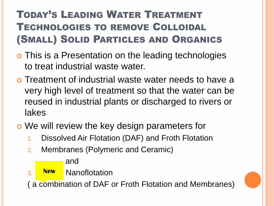
TODAY’S LEADING WATER TREATMENT
TECHNOLOGIES TO REMOVE COLLOIDAL
(SMALL) SOLID PARTICLES AND ORGANICS
This is a Presentation on the leading technologies
to treat industrial waste water.
Treatment of industrial waste water needs to have a
very high level of treatment so that the water can be
reused in industrial plants or discharged to rivers or
lakes
We will review the key design parameters for
1. Dissolved Air Flotation (DAF) and Froth Flotation
2. Membranes (Polymeric and Ceramic)
and
3. Nanoflotation
( a combination of DAF or Froth Flotation and Membranes)
New
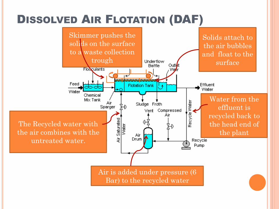
DISSOLVED AIR FLOTATION (DAF)
The Recycled water with
the air combines with the
untreated water.
Solids attach to
the air bubbles
and float to the
surface
Air is added under pressure (6
Bar) to the recycled water
Water from the
effluent is
recycled back to
the head end of
the plant
Skimmer pushes the
solids on the surface
to a waste collection
trough
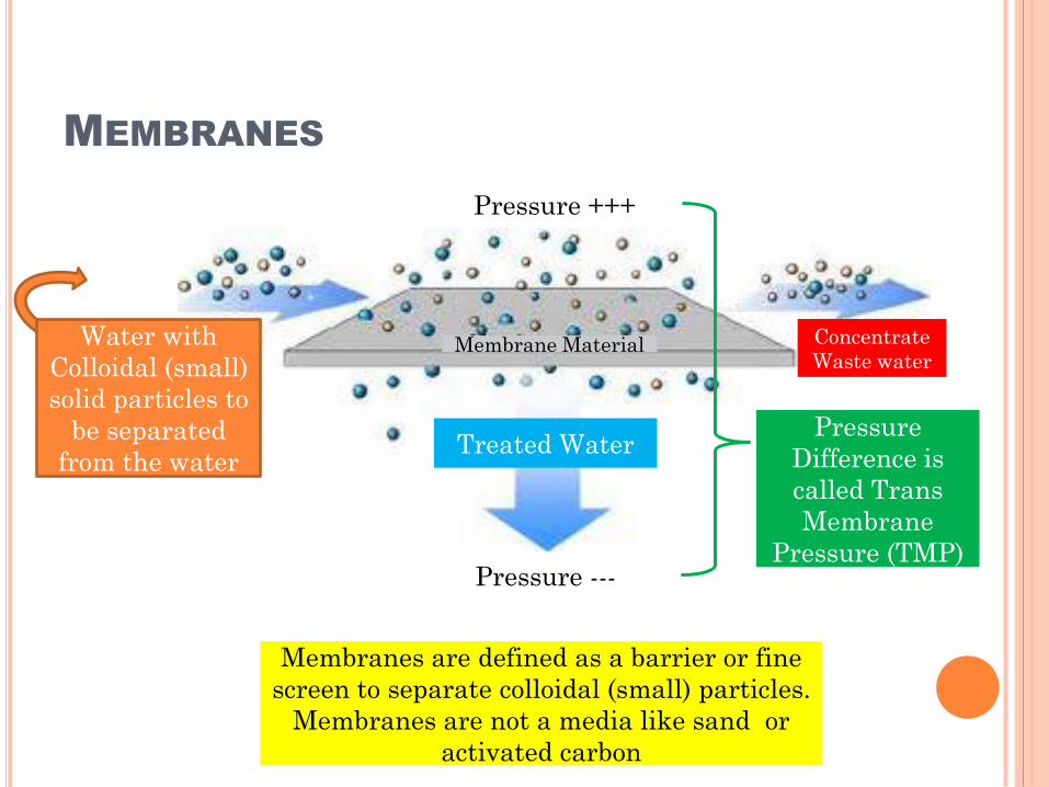
MEMBRANES
Water with
Colloidal (small)
solid particles to
be separated
from the waterTreated Water
Membrane Material Concentrate
Waste water
Pressure ---
Pressure +++
Membranes are defined as a barrier or fine
screen to separate colloidal (small) particles.
Membranes are not a media like sand or
activated carbon
Pressure
Difference is
called Trans
Membrane
Pressure (TMP)
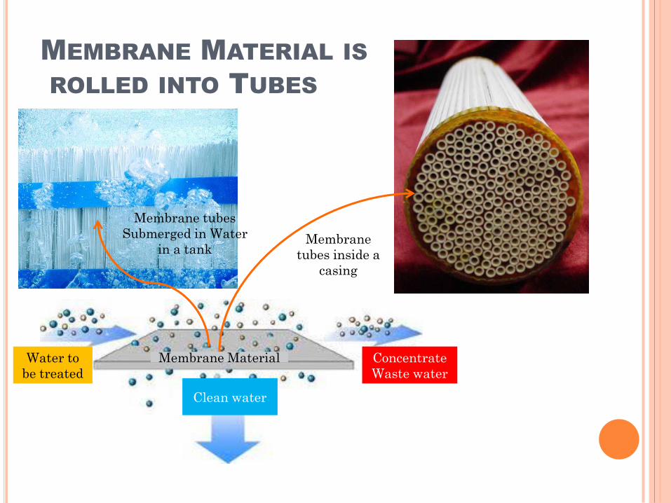
MEMBRANE MATERIAL IS
ROLLED INTO TUBES
Membrane Material Concentrate
Waste water
Water to
be treated
Clean water
Membrane tubes
Submerged in Water
in a tank Membrane
tubes inside a
casing
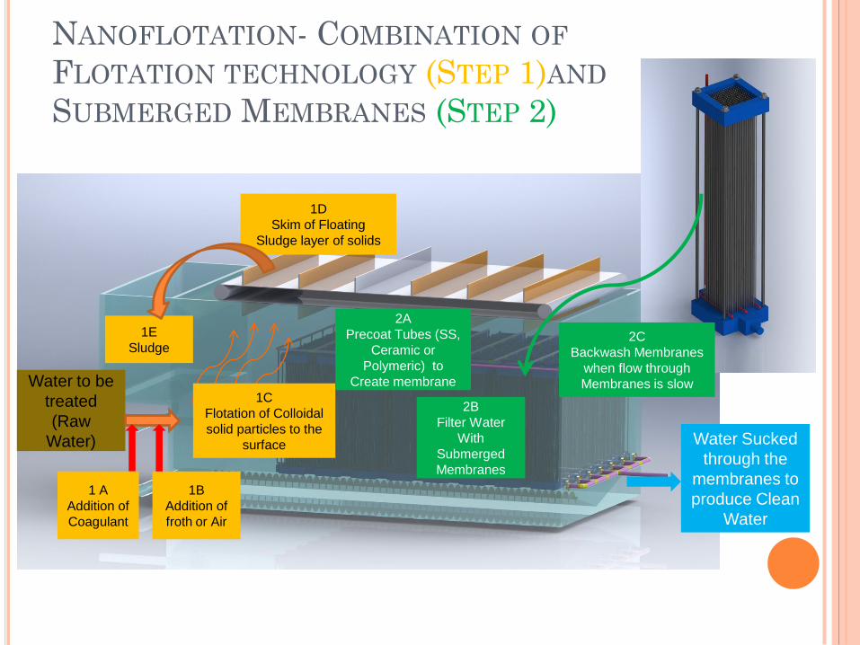
NANOFLOTATION- COMBINATION OF
FLOTATION TECHNOLOGY (STEP 1)AND
SUBMERGED MEMBRANES (STEP 2)
Water to be
treated
(Raw
Water)
1C
Flotation of Colloidal
solid particles to the
surface
1B
Addition of
froth or Air
1D
Skim of Floating
Sludge layer of solids
1 A
Addition of
Coagulant
2B
Filter Water
With
Submerged
Membranes
2C
Backwash Membranes
when flow through
Membranes is slow
1E
Sludge
Water Sucked
through the
membranes to
produce Clean
Water
2A
Precoat Tubes (SS,
Ceramic or
Polymeric) to
Create membrane
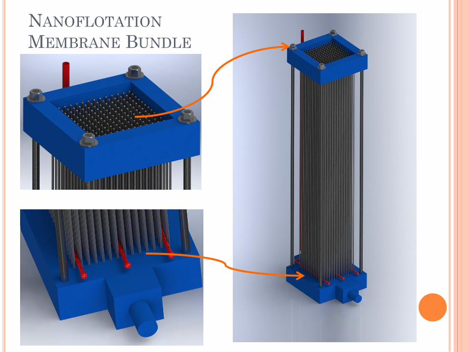
NANOFLOTATION
MEMBRANE BUNDLE
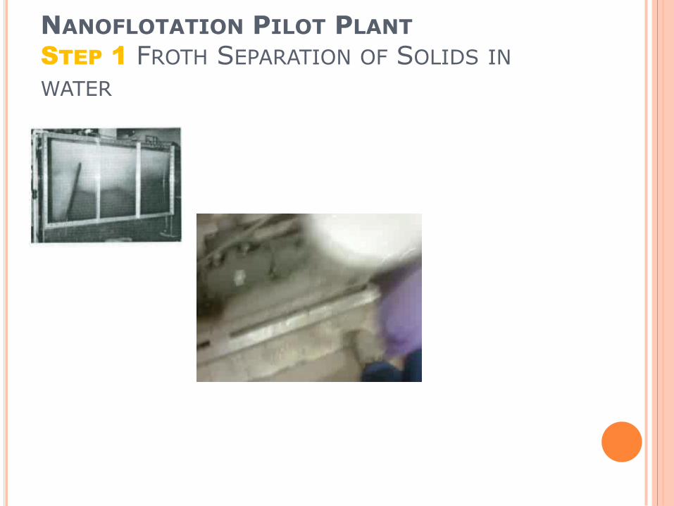
NANOFLOTATION PILOT PLANTSTEP 1 FROTH SEPARATION OF SOLIDS IN
WATER
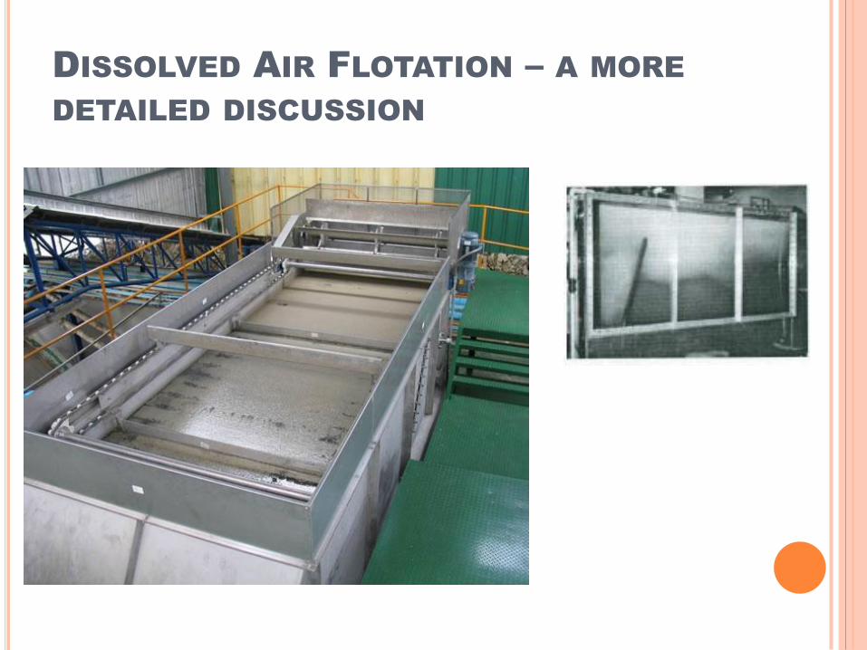
DISSOLVED AIR FLOTATION – A MORE
DETAILED DISCUSSION
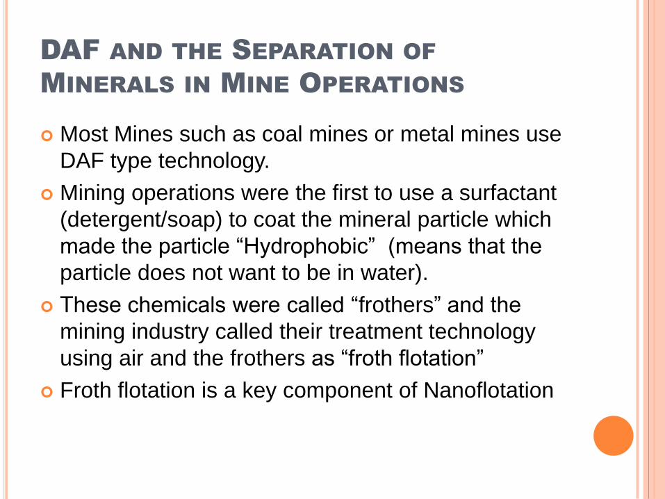
DAF AND THE SEPARATION OF
MINERALS IN MINE OPERATIONS
Most Mines such as coal mines or metal mines use
DAF type technology.
Mining operations were the first to use a surfactant
(detergent/soap) to coat the mineral particle which
made the particle “Hydrophobic” (means that the
particle does not want to be in water).
These chemicals were called “frothers” and the
mining industry called their treatment technology
using air and the frothers as “froth flotation”
Froth flotation is a key component of Nanoflotation
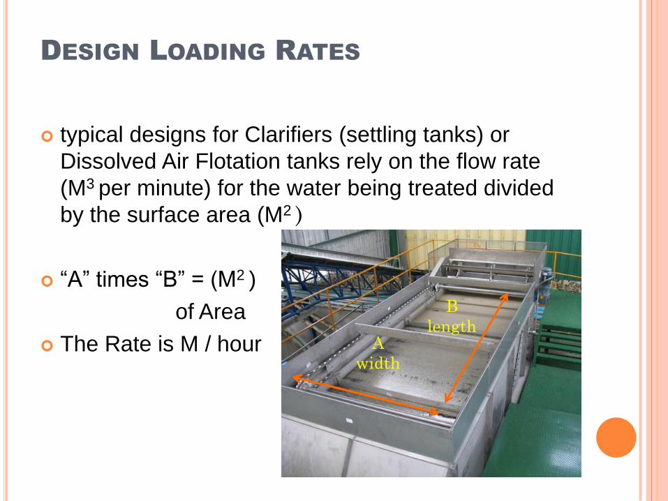
DESIGN LOADING RATES
typical designs for Clarifiers (settling tanks) or
Dissolved Air Flotation tanks rely on the flow rate
(M3 per minute) for the water being treated divided
by the surface area (M2 )
“A” times “B” = (M2 )
of Area
The Rate is M / hour A
width
B
length
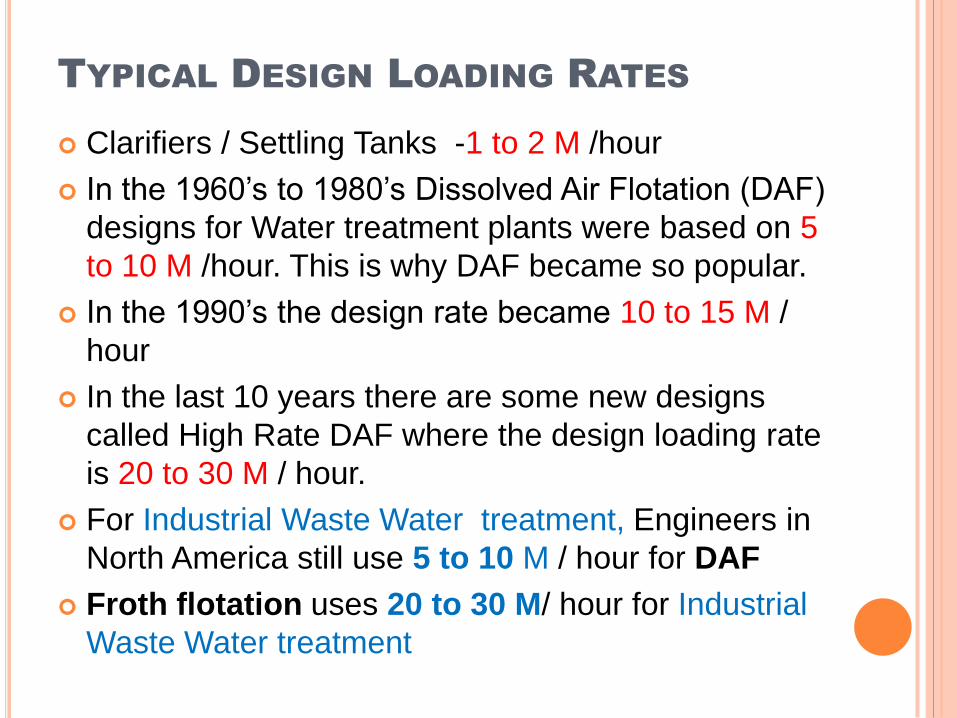
TYPICAL DESIGN LOADING RATES
Clarifiers / Settling Tanks -1 to 2 M /hour
In the 1960’s to 1980’s Dissolved Air Flotation (DAF)
designs for Water treatment plants were based on 5
to 10 M /hour. This is why DAF became so popular.
In the 1990’s the design rate became 10 to 15 M /
hour
In the last 10 years there are some new designs
called High Rate DAF where the design loading rate
is 20 to 30 M / hour.
For Industrial Waste Water treatment, Engineers in
North America still use 5 to 10 M / hour for DAF
Froth flotation uses 20 to 30 M/ hour for Industrial
Waste Water treatment
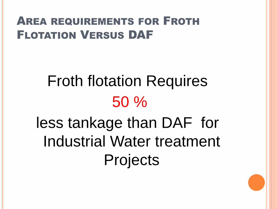
AREA REQUIREMENTS FOR FROTH
FLOTATION VERSUS DAF
Froth flotation Requires
50 %
less tankage than DAF for
Industrial Water treatment
Projects
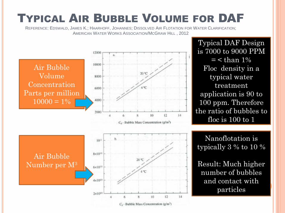
TYPICAL AIR BUBBLE VOLUME FOR DAFREFERENCE: EDSWALD, JAMES K.; HAARHOFF, JOHANNES; DISSOLVED AIR FLOTATION FOR WATER CLARIFICATION;
AMERICAN WATER WORKS ASSOCIATION/MCGRAW HILL , 2012
Air Bubble
Volume
Concentration
Parts per million
10000 = 1%
Air Bubble
Number per M3
Typical DAF Design
is 7000 to 9000 PPM
= < than 1%
Floc density in a
typical water
treatment
application is 90 to
100 ppm. Therefore
the ratio of bubbles to
floc is 100 to 1
Nanoflotation is
typically 3 % to 10 %
Result: Much higher
number of bubbles
and contact with
particles
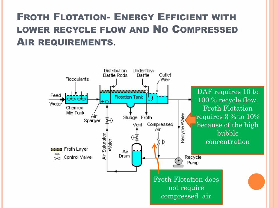
FROTH FLOTATION- ENERGY EFFICIENT WITH
LOWER RECYCLE FLOW AND NO COMPRESSED
AIR REQUIREMENTS.
DAF requires 10 to
100 % recycle flow.
Froth Flotation
requires 3 % to 10%
because of the high
bubble
concentration
Froth Flotation does
not require
compressed air
OPERATING COSTS- FROTH FLOTATION
MORE EXPENSIVE
Froth Flotation uses Surfactant
Assuming Surfactant cost is $2000/ M3 the cost
per M3 of treated water is $0.10
Dissolved Air Flotation relies on Recycle water
pumping and compressed air. The total amount
of energy consumption is approximately 0.05
KwH per M3. At $0.10 per KwH the cost per M3 is
$0.005
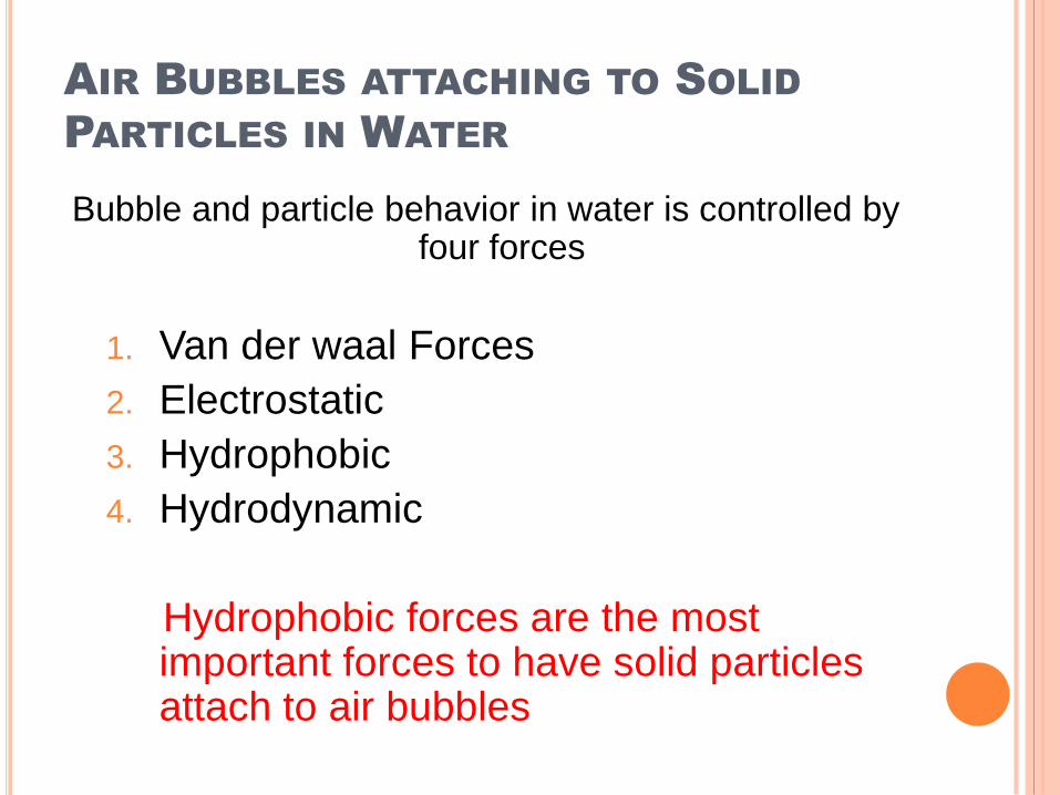
AIR BUBBLES ATTACHING TO SOLID
PARTICLES IN WATER
Bubble and particle behavior in water is controlled by four forces
1. Van der waal Forces
2. Electrostatic
3. Hydrophobic
4. Hydrodynamic
Hydrophobic forces are the most important forces to have solid particles attach to air bubbles
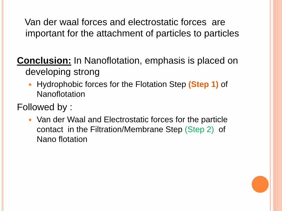
Van der waal forces and electrostatic forces are
important for the attachment of particles to particles
Conclusion: In Nanoflotation, emphasis is placed on
developing strong
Hydrophobic forces for the Flotation Step (Step 1) of
Nanoflotation
Followed by :
Van der Waal and Electrostatic forces for the particle
contact in the Filtration/Membrane Step (Step 2) of
Nano flotation
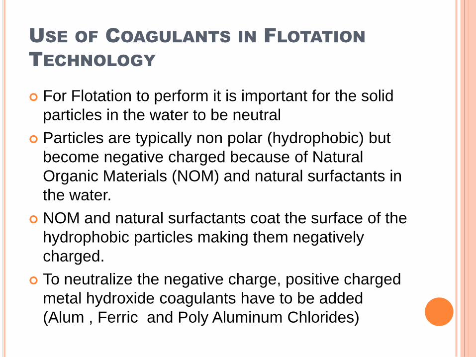
USE OF COAGULANTS IN FLOTATION
TECHNOLOGY
For Flotation to perform it is important for the solid
particles in the water to be neutral
Particles are typically non polar (hydrophobic) but
become negative charged because of Natural
Organic Materials (NOM) and natural surfactants in
the water.
NOM and natural surfactants coat the surface of the
hydrophobic particles making them negatively
charged.
To neutralize the negative charge, positive charged
metal hydroxide coagulants have to be added
(Alum , Ferric and Poly Aluminum Chlorides)
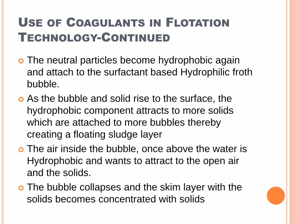
USE OF COAGULANTS IN FLOTATION
TECHNOLOGY-CONTINUED
The neutral particles become hydrophobic again
and attach to the surfactant based Hydrophilic froth
bubble.
As the bubble and solid rise to the surface, the
hydrophobic component attracts to more solids
which are attached to more bubbles thereby
creating a floating sludge layer
The air inside the bubble, once above the water is
Hydrophobic and wants to attract to the open air
and the solids.
The bubble collapses and the skim layer with the
solids becomes concentrated with solids
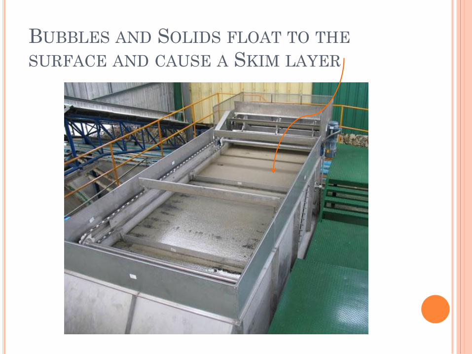
BUBBLES AND SOLIDS FLOAT TO THE
SURFACE AND CAUSE A SKIM LAYER
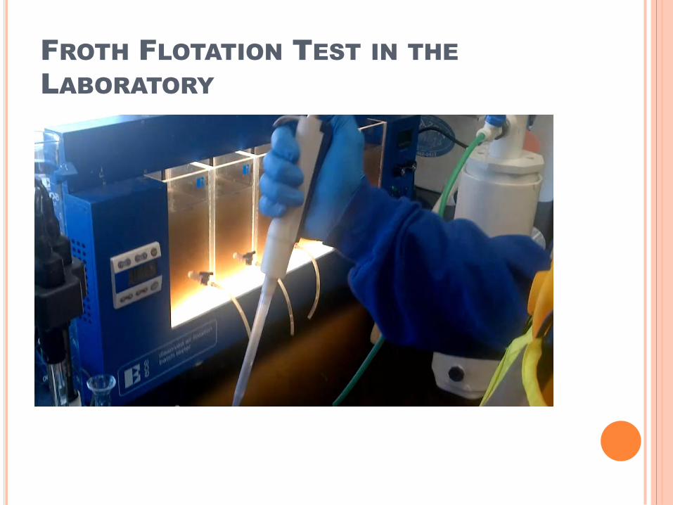
FROTH FLOTATION TEST IN THE
LABORATORY
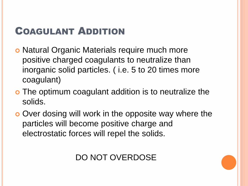
COAGULANT ADDITION
Natural Organic Materials require much more
positive charged coagulants to neutralize than
inorganic solid particles. ( i.e. 5 to 20 times more
coagulant)
The optimum coagulant addition is to neutralize the
solids.
Over dosing will work in the opposite way where the
particles will become positive charge and
electrostatic forces will repel the solids.
DO NOT OVERDOSE
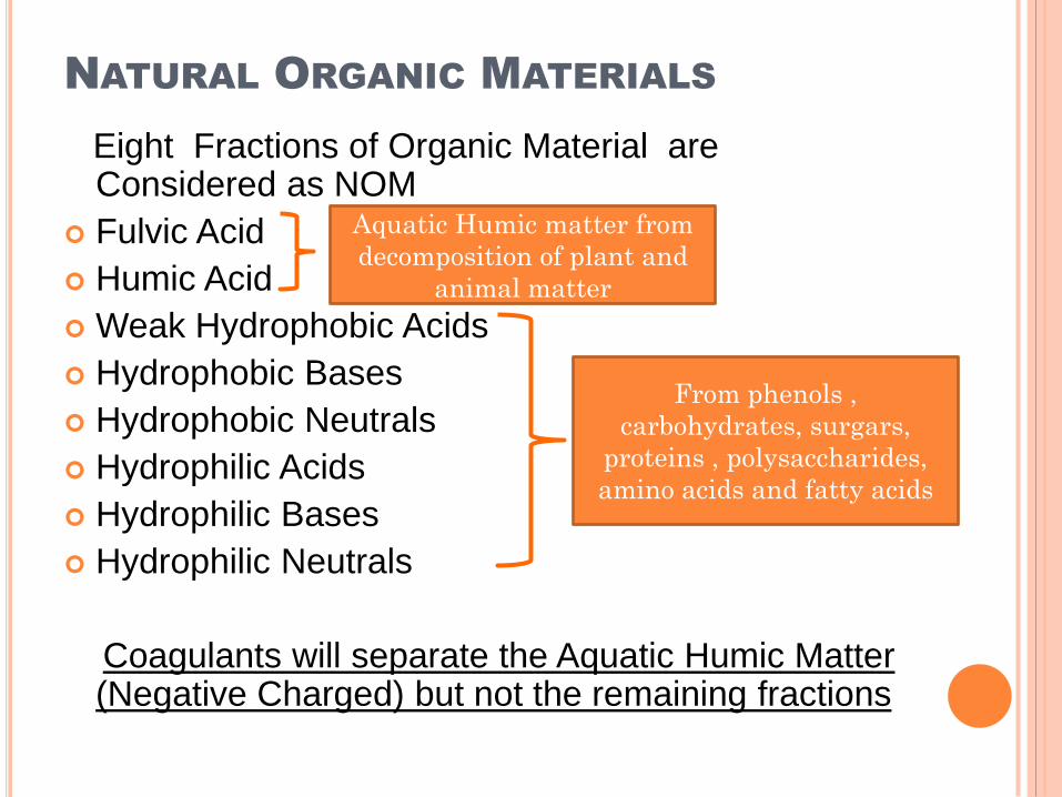
NATURAL ORGANIC MATERIALS
Eight Fractions of Organic Material are Considered as NOM
Fulvic Acid
Humic Acid
Weak Hydrophobic Acids
Hydrophobic Bases
Hydrophobic Neutrals
Hydrophilic Acids
Hydrophilic Bases
Hydrophilic Neutrals
Coagulants will separate the Aquatic Humic Matter (Negative Charged) but not the remaining fractions
Aquatic Humic matter from
decomposition of plant and
animal matter
From phenols ,
carbohydrates, surgars,
proteins , polysaccharides,
amino acids and fatty acids
IMPACT OF HARDNESS IN WATER AND TOTAL
DISSOLVED SOLIDS (TDS) ON COAGULATION
The Harder the water or the higher the TDS level
the easier it will be to coagulate the solid particles
in the water
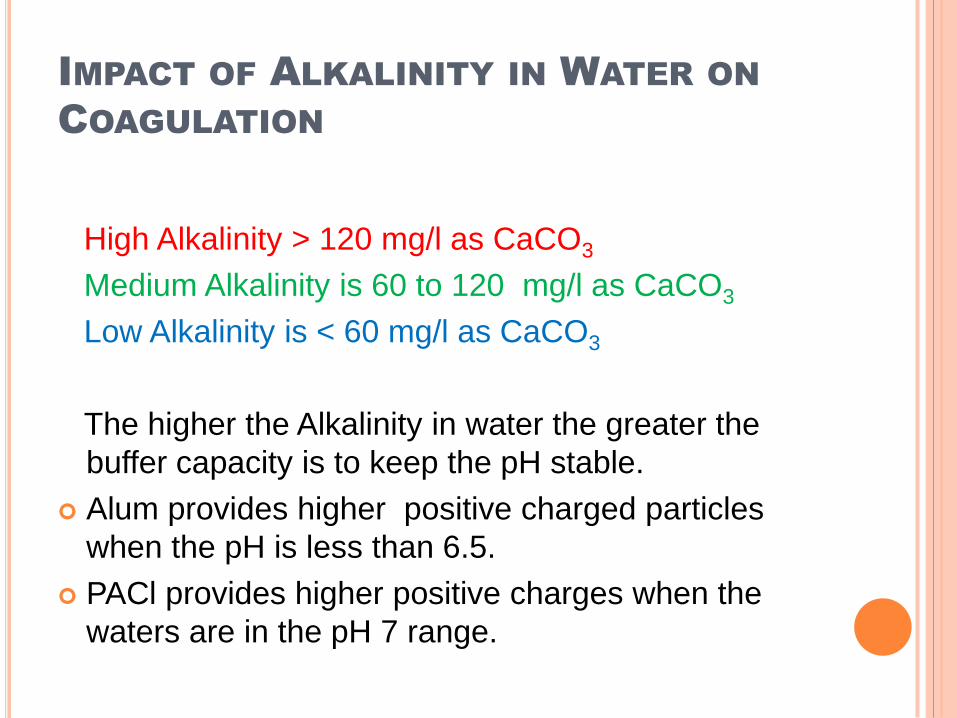
IMPACT OF ALKALINITY IN WATER ON
COAGULATION
High Alkalinity > 120 mg/l as CaCO3
Medium Alkalinity is 60 to 120 mg/l as CaCO3
Low Alkalinity is < 60 mg/l as CaCO3
The higher the Alkalinity in water the greater the
buffer capacity is to keep the pH stable.
Alum provides higher positive charged particles
when the pH is less than 6.5.
PACl provides higher positive charges when the
waters are in the pH 7 range.
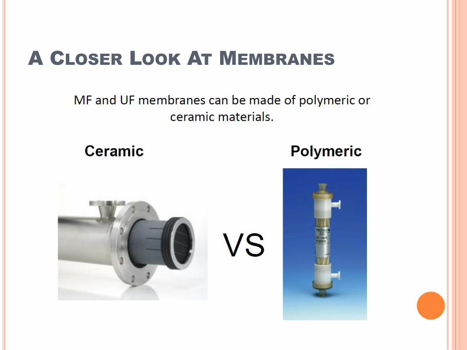
A CLOSER LOOK AT MEMBRANES
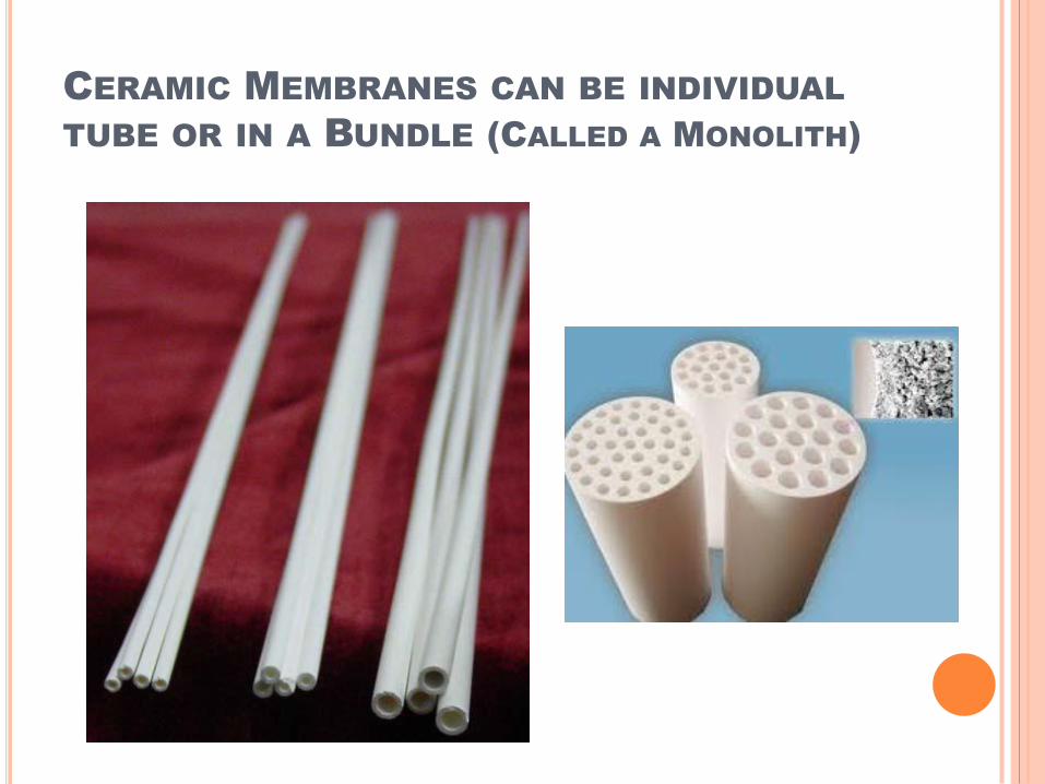
CERAMIC MEMBRANES CAN BE INDIVIDUAL
TUBE OR IN A BUNDLE (CALLED A MONOLITH)
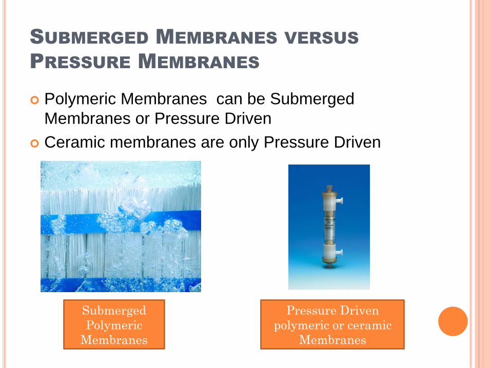
SUBMERGED MEMBRANES VERSUS
PRESSURE MEMBRANES
Polymeric Membranes can be Submerged
Membranes or Pressure Driven
Ceramic membranes are only Pressure Driven
Submerged
Polymeric
Membranes
Pressure Driven
polymeric or ceramic
Membranes
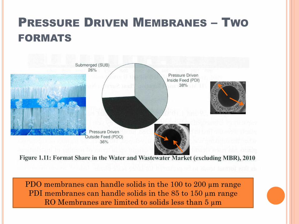
PRESSURE DRIVEN MEMBRANES – TWO
FORMATS
PDO membranes can handle solids in the 100 to 200 µm range
PDI membranes can handle solids in the 85 to 150 µm range
RO Membranes are limited to solids less than 5 µm
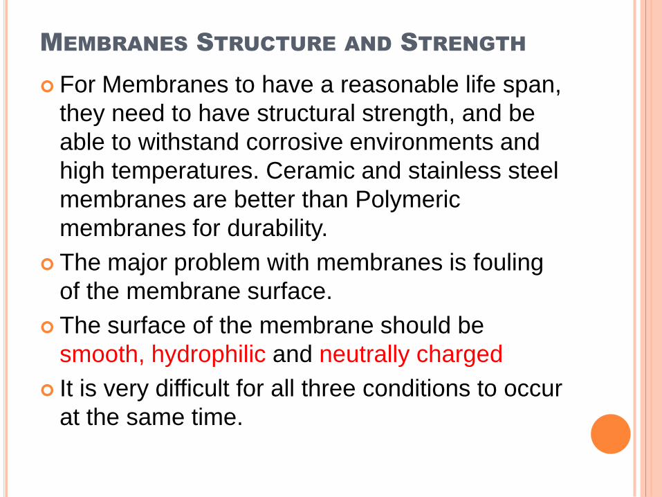
MEMBRANES STRUCTURE AND STRENGTH
For Membranes to have a reasonable life span,
they need to have structural strength, and be
able to withstand corrosive environments and
high temperatures. Ceramic and stainless steel
membranes are better than Polymeric
membranes for durability.
The major problem with membranes is fouling
of the membrane surface.
The surface of the membrane should be
smooth, hydrophilic and neutrally charged
It is very difficult for all three conditions to occur
at the same time.
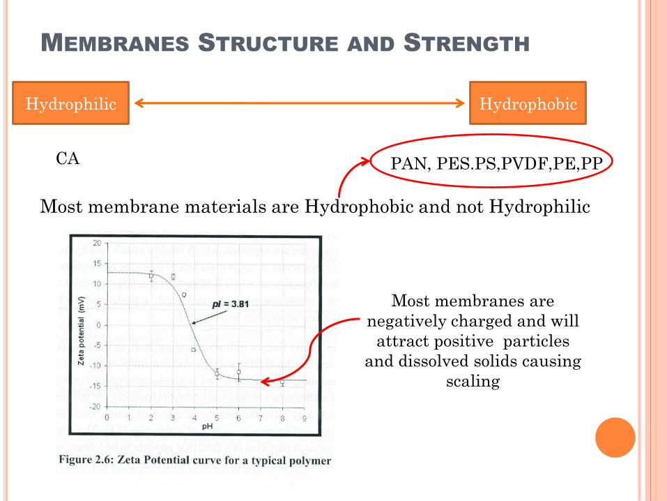
MEMBRANES STRUCTURE AND STRENGTH
.
Most membrane materials are Hydrophobic and not Hydrophilic
Hydrophilic Hydrophobic
CA PAN, PES.PS,PVDF,PE,PP
Most membranes are
negatively charged and will
attract positive particles
and dissolved solids causing
scaling
MEMBRANES BECOME FOULED
It is impossible to have the perfect membrane surface
Not smooth
Most membrane materials are Hydrophobic
Membranes surface are typically negative charged.
As a result membranes become fouled with the colloidal particles.
CAUSES OF COLLOIDAL SOLID FOULING
ON MEMBRANES
Three of the same four forces discussed earlier,
regarding the attraction of bubbles to colloidal
solids, are the same forces that cause the fouling
on membranes
1. Van der Waal forces which are important in media
filtration where colloidal particles attach to other
solid particles
2. Electrostatic forces where opposites attract
3. Hydrophobic forces where the particles are driven
out of the water to the Hydrophobic surfaces
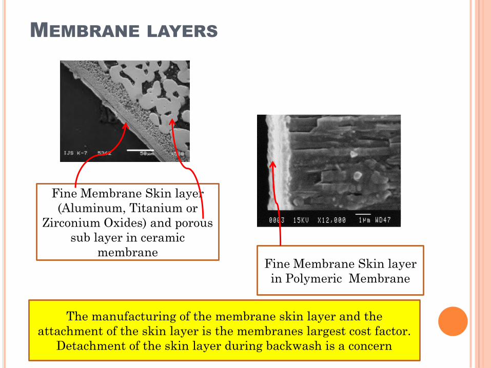
MEMBRANE LAYERS
Fine Membrane Skin layer
(Aluminum, Titanium or
Zirconium Oxides) and porous
sub layer in ceramic
membraneFine Membrane Skin layer
in Polymeric Membrane
The manufacturing of the membrane skin layer and the
attachment of the skin layer is the membranes largest cost factor.
Detachment of the skin layer during backwash is a concern
LIMITED PRESSURE AND FLUX (FLOW
RATE) FOR MEMBRANES
To reduce fouling the pressure across the
membrane (TMP) has to be limited to a maximum
of 1 bar.
For submerged membranes the maximum TMP is
0.7 bar
Membranes also need to operate at a flux (flow)
rate that controls fouling of the membrane. This flux
rate is called the “Threshold Flux rate”
If the flux is above the Threshold Flux rate. Fouling
of the membrane will be very fast
CLEANING MEMBRANES
Efficiency of the Cleaning Process depends on
1. Chemicals Used
2. Concentration
3. Contact Time
4. Temperature
5. Backwash velocity
All of this can create complications!
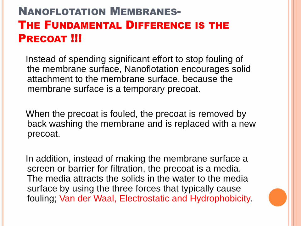
NANOFLOTATION MEMBRANES-
THE FUNDAMENTAL DIFFERENCE IS THE
PRECOAT !!!
Instead of spending significant effort to stop fouling of the membrane surface, Nanoflotation encourages solid attachment to the membrane surface, because the membrane surface is a temporary precoat.
When the precoat is fouled, the precoat is removed by back washing the membrane and is replaced with a new precoat.
In addition, instead of making the membrane surface a screen or barrier for filtration, the precoat is a media. The media attracts the solids in the water to the media surface by using the three forces that typically cause fouling; Van der Waal, Electrostatic and Hydrophobicity.
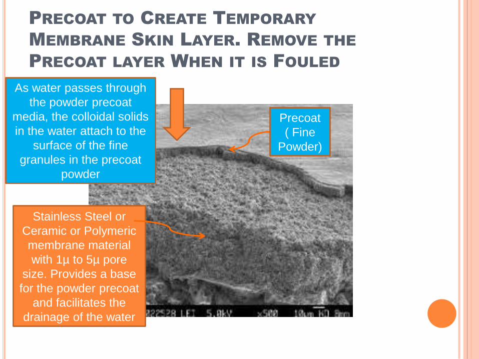
PRECOAT TO CREATE TEMPORARY
MEMBRANE SKIN LAYER. REMOVE THE
PRECOAT LAYER WHEN IT IS FOULED
As water passes through
the powder precoat
media, the colloidal solids
in the water attach to the
surface of the fine
granules in the precoat
powder
Stainless Steel or
Ceramic or Polymeric
membrane material
with 1µ to 5µ pore
size. Provides a base
for the powder precoat
and facilitates the
drainage of the water
Precoat
( Fine
Powder)
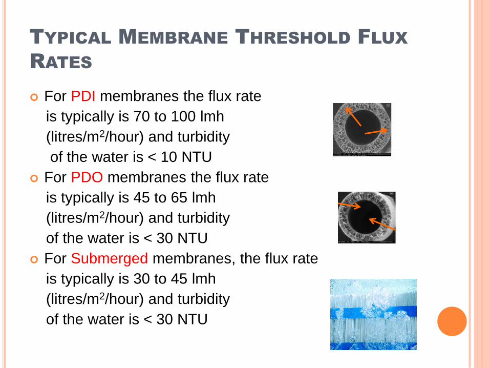
TYPICAL MEMBRANE THRESHOLD FLUX
RATES
For PDI membranes the flux rate
is typically is 70 to 100 lmh
(litres/m2/hour) and turbidity
of the water is < 10 NTU
For PDO membranes the flux rate
is typically is 45 to 65 lmh
(litres/m2/hour) and turbidity
of the water is < 30 NTU
For Submerged membranes, the flux rate
is typically is 30 to 45 lmh
(litres/m2/hour) and turbidity
of the water is < 30 NTU
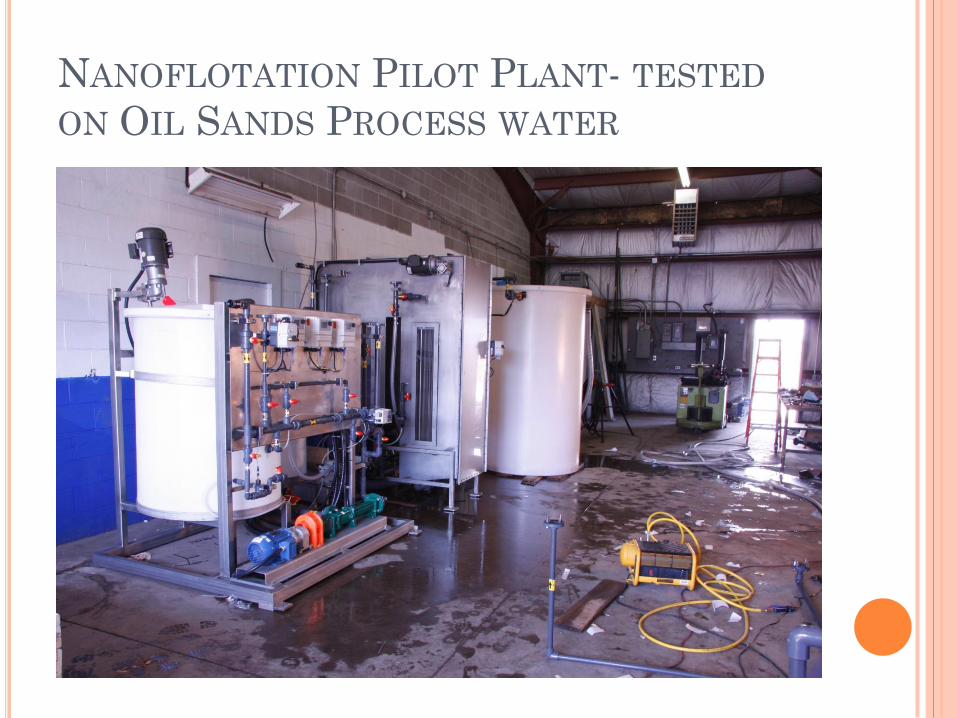
NANOFLOTATION PILOT PLANT- TESTED
ON OIL SANDS PROCESS WATER
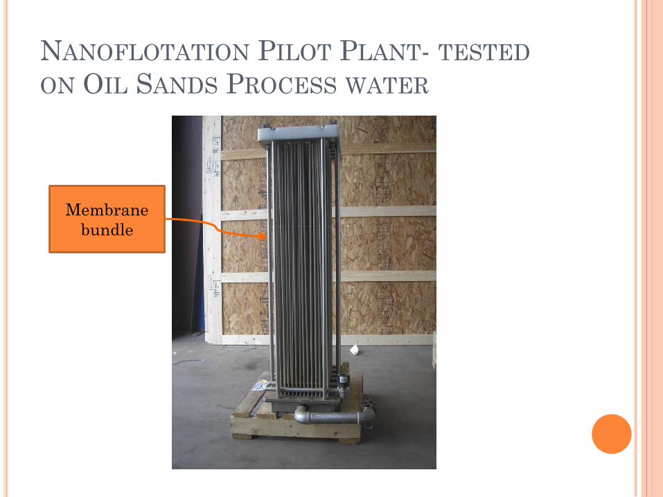
NANOFLOTATION PILOT PLANT- TESTED
ON OIL SANDS PROCESS WATER
Membrane
bundle
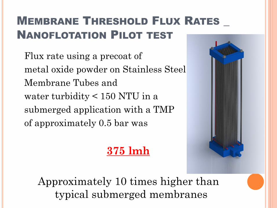
MEMBRANE THRESHOLD FLUX RATES _
NANOFLOTATION PILOT TEST
Flux rate using a precoat of
metal oxide powder on Stainless Steel
Membrane Tubes and
water turbidity < 150 NTU in a
submerged application with a TMP
of approximately 0.5 bar was
375 lmh
Approximately 10 times higher than
typical submerged membranes
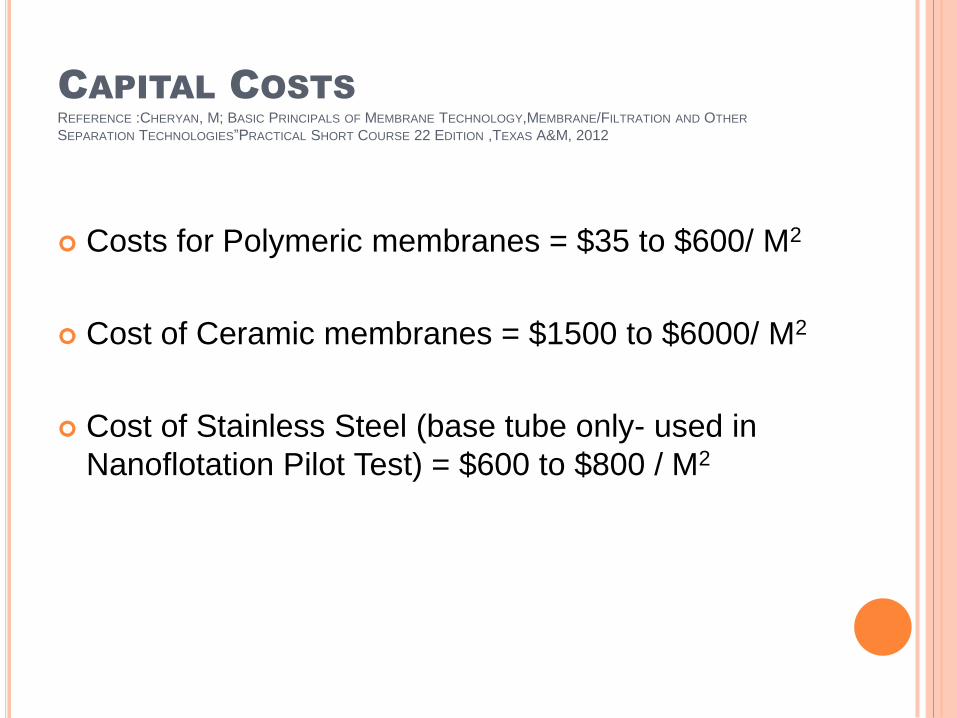
CAPITAL COSTS
REFERENCE :CHERYAN, M; BASIC PRINCIPALS OF MEMBRANE TECHNOLOGY,MEMBRANE/FILTRATION AND OTHER
SEPARATION TECHNOLOGIES”PRACTICAL SHORT COURSE 22 EDITION ,TEXAS A&M, 2012
Costs for Polymeric membranes = $35 to $600/ M2
Cost of Ceramic membranes = $1500 to $6000/ M2
Cost of Stainless Steel (base tube only- used in
Nanoflotation Pilot Test) = $600 to $800 / M2
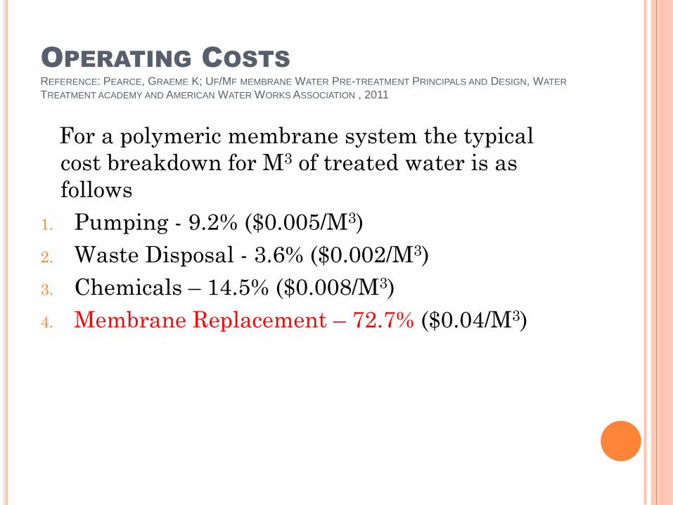
OPERATING COSTS
REFERENCE: PEARCE, GRAEME K; UF/MF MEMBRANE WATER PRE-TREATMENT PRINCIPALS AND DESIGN, WATER
TREATMENT ACADEMY AND AMERICAN WATER WORKS ASSOCIATION , 2011
For a polymeric membrane system the typical
cost breakdown for M3 of treated water is as
follows
1. Pumping - 9.2% ($0.005/M3)
2. Waste Disposal - 3.6% ($0.002/M3)
3. Chemicals – 14.5% ($0.008/M3)
4. Membrane Replacement – 72.7% ($0.04/M3)
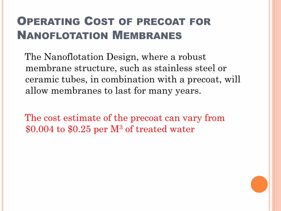
OPERATING COST OF PRECOAT FOR
NANOFLOTATION MEMBRANES
The Nanoflotation Design, where a robust
membrane structure, such as stainless steel or
ceramic tubes, in combination with a precoat, will
allow membranes to last for many years.
The cost estimate of the precoat can vary from
$0.004 to $0.25 per M3 of treated water
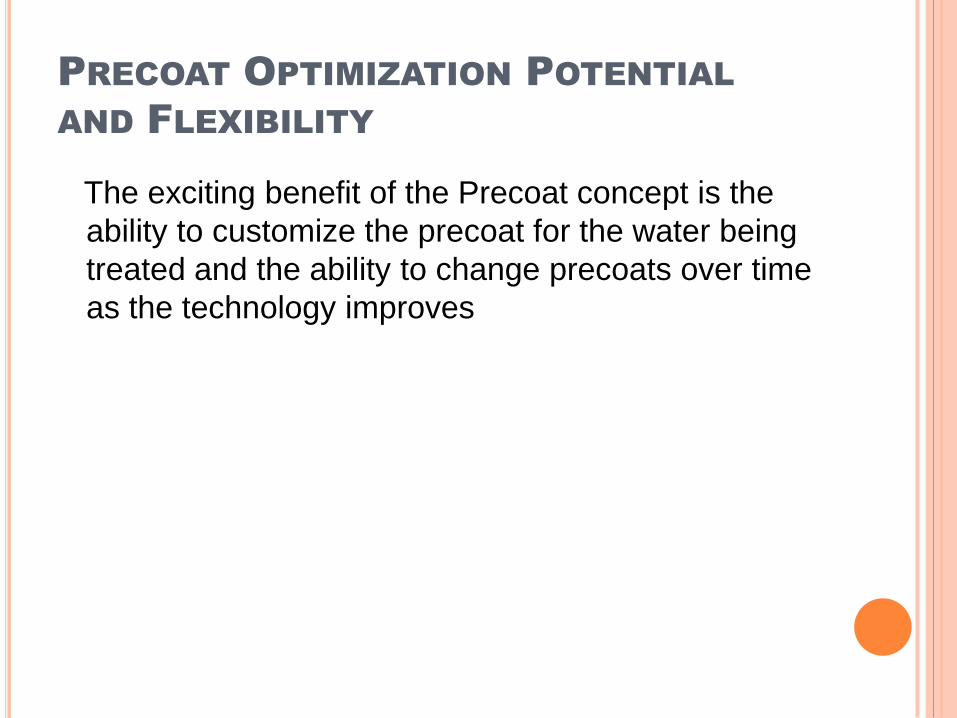
PRECOAT OPTIMIZATION POTENTIAL
AND FLEXIBILITY
The exciting benefit of the Precoat concept is the
ability to customize the precoat for the water being
treated and the ability to change precoats over time
as the technology improves
SUMMARY
Nanoflotation has two components
Step 1 Flotation technology
Step 2 Membrane technology
STEP 1:The Flotation Technology can be either Froth
Flotation or Dissolved Air Flotation ( DAF)
Froth flotation is a much lower energy option but requires
surfactant which makes it a more expensive operating cost
It has a lower capital cost because hydraulic loading rates are
higher than DAF technology. Tankage can be 50% smaller
Froth flotation has much higher bubble concentration (3 to
10%) versus DAF (0.7 to 0.9%).
Froth flotation may be a better treatment option for most
Industrial Waste waters
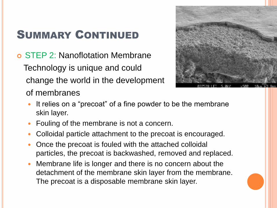
SUMMARY CONTINUED
STEP 2: Nanoflotation Membrane
Technology is unique and could
change the world in the development
of membranes
It relies on a “precoat” of a fine powder to be the membrane
skin layer.
Fouling of the membrane is not a concern.
Colloidal particle attachment to the precoat is encouraged.
Once the precoat is fouled with the attached colloidal
particles, the precoat is backwashed, removed and replaced.
Membrane life is longer and there is no concern about the
detachment of the membrane skin layer from the membrane.
The precoat is a disposable membrane skin layer.
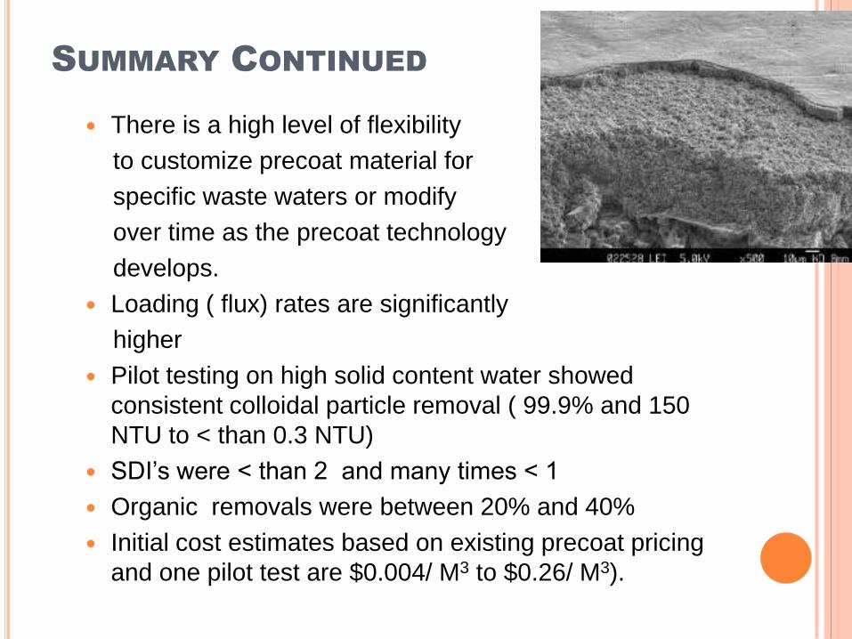
SUMMARY CONTINUED
There is a high level of flexibility
to customize precoat material for
specific waste waters or modify
over time as the precoat technology
develops.
Loading ( flux) rates are significantly
higher
Pilot testing on high solid content water showed
consistent colloidal particle removal ( 99.9% and 150
NTU to < than 0.3 NTU)
SDI’s were < than 2 and many times < 1
Organic removals were between 20% and 40%
Initial cost estimates based on existing precoat pricing
and one pilot test are $0.004/ M3 to $0.26/ M3).