dissolved air flotation (daf) optimizationdaf optimization –fog removal case study what is...
TRANSCRIPT

32nd VWEA IW&P Conference March 7, 2016
Christopher Petree, PE, Timmons Group
John Dunford, CWT, Bond Water Technologies
Dissolved Air Flotation (DAF)
Optimization

Discussion Outline
What is Dissolved Air Floatation (DAF)
How does DAF work
Where is DAF typically used/most effective
DAF Design Considerations
Advancements in DAF
DAF Optimization – FOG Removal Case Study

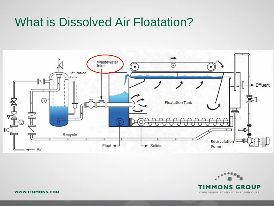
What is Dissolved Air Floatation?
A process using air bubbles to assist with the removal of
suspended matter.
Compressed air is introduced to the waste stream and
mixed with suspended particles causing them to become
buoyant.
Flow is slowed in a settling/floatation tank allowing
buoyant particles to float to the top of the tank where they
are skimmed off
Dense solids are collected at the bottom of the tank
What is Dissolved Air Floatation?

Pre-DAF Chemical Conditioning
Waste stream can be introduced to DAF untreated Some manufactures claim as high as 85% solids removal
or
To aid in the efficiency of floatable particle formation, it
is very common to chemically condition the wastewater
prior to the DAF
Coagulant (typically metal salts)
Flocculant (polymer)
Solids removal as high as 98%
Removal efficiencies depend on many factors!

Pre-DAF Chemical Conditioning
Untreated Wastewater
Waste streams carry a consistent charge; usually slightly
negative, but can also be positive
-
-
-
--
-
-
-

Pre-DAF Chemical Conditioning
Coagulant Applied
Charge neutralization of colloidal particles in the waste
stream to promote clumping together to form light floc
-
-
-
-
-
-
-
-
+
+
+ +
+
++
+
+
++
+

Pre-DAF Chemical Conditioning
Flocculant Applied
Promotes clumping of floc particles
-+
-+
+
-+
+
-+
-+
+
-+
-+
-+
+
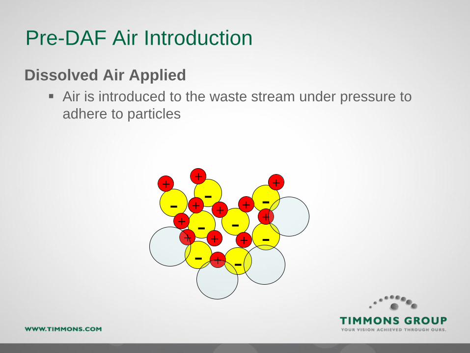
Pre-DAF Air Introduction
Dissolved Air Applied
Air is introduced to the waste stream under pressure to
adhere to particles
--
-
- -
--
-+
+
+
+
+
+
+
+
+
++
+
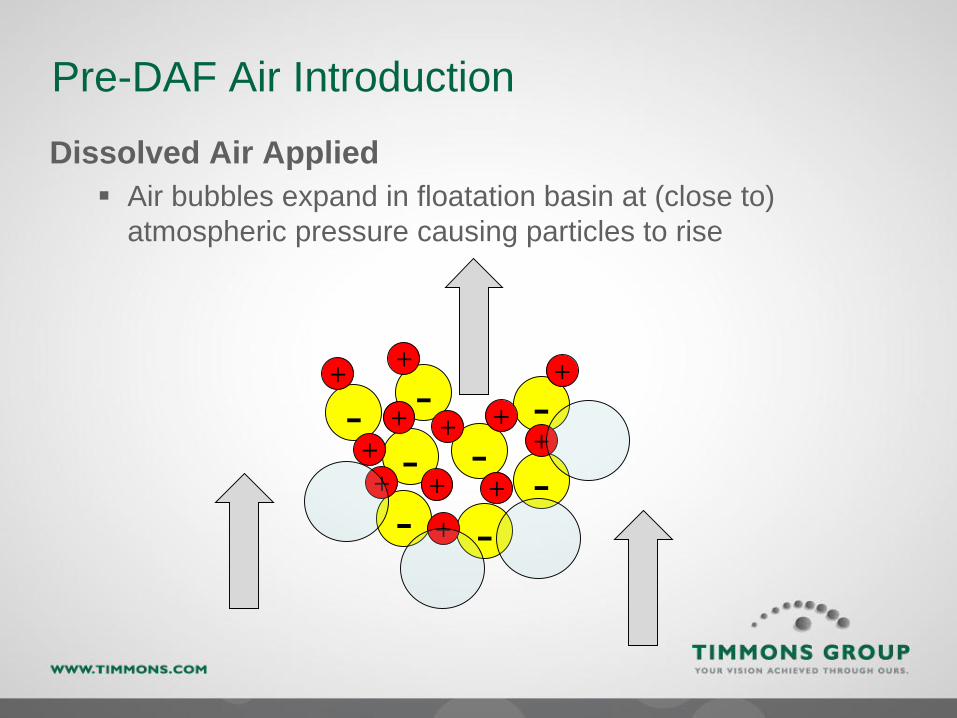
Pre-DAF Air Introduction
Dissolved Air Applied
Air bubbles expand in floatation basin at (close to)
atmospheric pressure causing particles to rise
--
-
- -
--
-+
+
+
+
+
+
+
+
+
++
+

DAF Foam

Where is Dissolved Air Floatation Used?
DAF systems are most commonly used in industrial
applications to treat waste streams to locality standards
prior to discharge
Common Industries:
Food processing
Paper mills
Oil refineries
Chemical plants
Large-scale DAF systems can also be used for
municipal wastewater treatment
Sludge thickening
Solids clarification
Textile industry
Meat processing
Bakeries
Other high-solids waste streams
Algae removal

Typical Industrial DAF

Municipal DAF

Municipal DAF

Municipal DAF
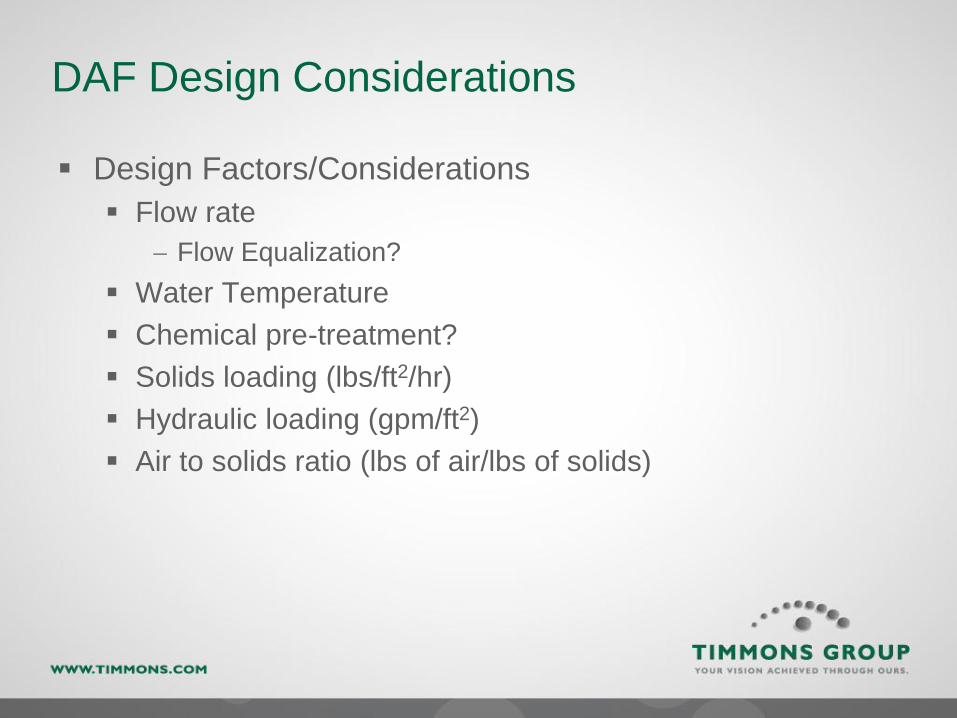
DAF Design Considerations
Design Factors/Considerations
Flow rate
Flow Equalization?
Water Temperature
Chemical pre-treatment?
Solids loading (lbs/ft2/hr)
Hydraulic loading (gpm/ft2)
Air to solids ratio (lbs of air/lbs of solids)

DAF Design Considerations
Saturator Pressure: Usually 60 – 90 PSI
As water temperature increases, saturator pressure needs to
increase to achieve similar saturation levels
Bubbles: 0.01 to 0.10 millimeters
Too large, the bubbles wont interact with enough solids and
wont “grab” the particles
Too small, not enough buoyant force
Hydraulic loading: 0.3 to 3.0, 4.0 gpm/ft2 MAX
(Q + R) ÷ DAF surface area
• Q = DAF influent flow rate (gpm)
• R = internal recycle rate (gpm)
• Typically between 15 and 25% of Q
DAF Design Considerations
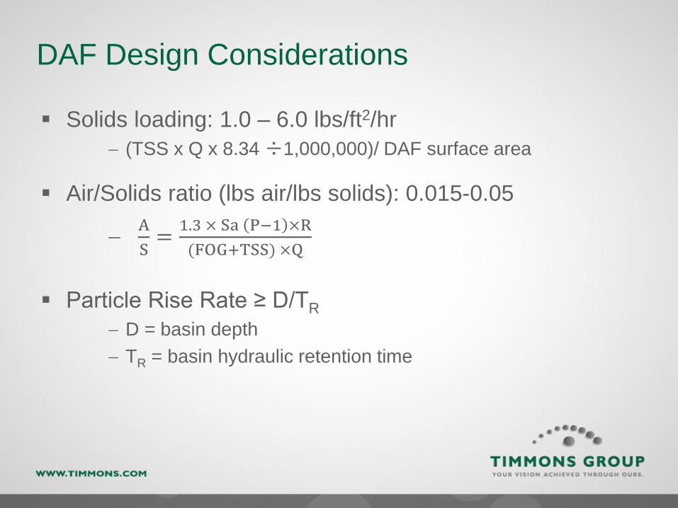
Solids loading: 1.0 – 6.0 lbs/ft2/hr
(TSS x Q x 8.34 ÷1,000,000)/ DAF surface area
Air/Solids ratio (lbs air/lbs solids): 0.015-0.05
A
S=
1.3 × Sa P−1 ×R
(FOG+TSS) ×Q
Particle Rise Rate ≥ D/TR
D = basin depth
TR = basin hydraulic retention time

DAF Advantages and Disadvantages
Advantages:
• High removal efficiency
• Small footprint
• Relatively low chemical
consumption
Disadvantages:
• Operational complexity
• Power consumption
• Shelter typically required

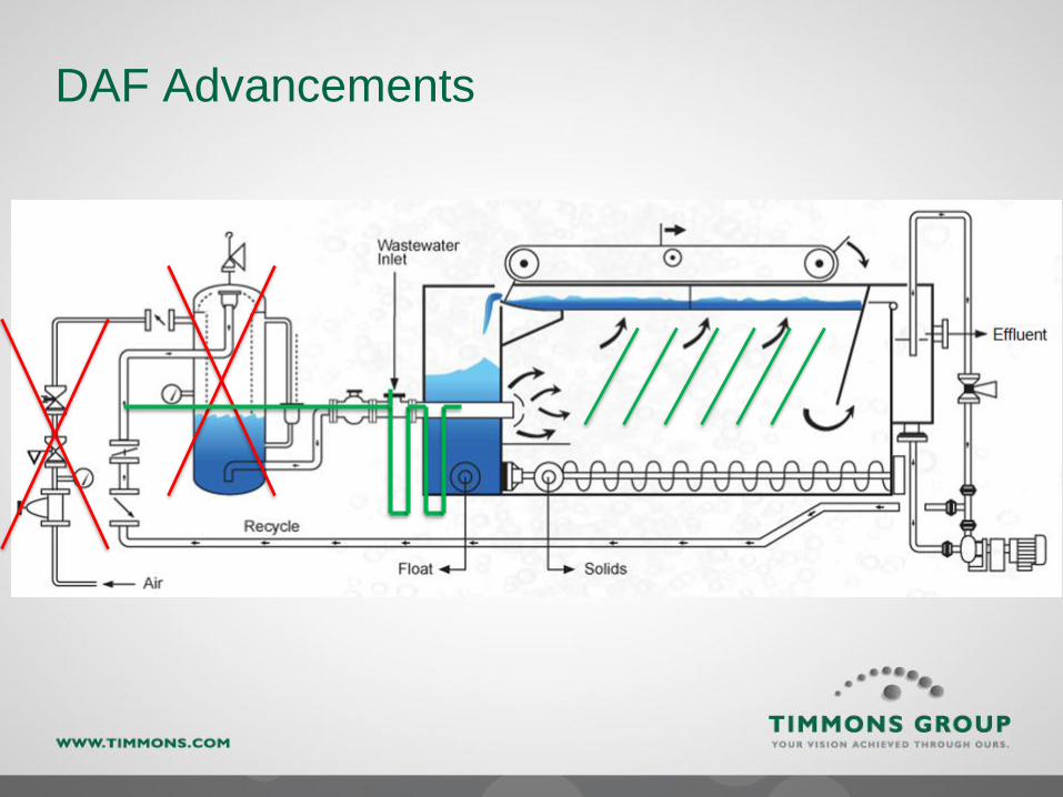
DAF Advancements
Air entrainment methods
Removal of saturation tank by using air-handling pumps
Influent mixing techniques
Floc tubes
Inclined (lamella-style) plates
DAF Advancements

DAF Advancements

DAF Advancements
Every industry has different treatment needs and every
DAF manufacturer has a different design!
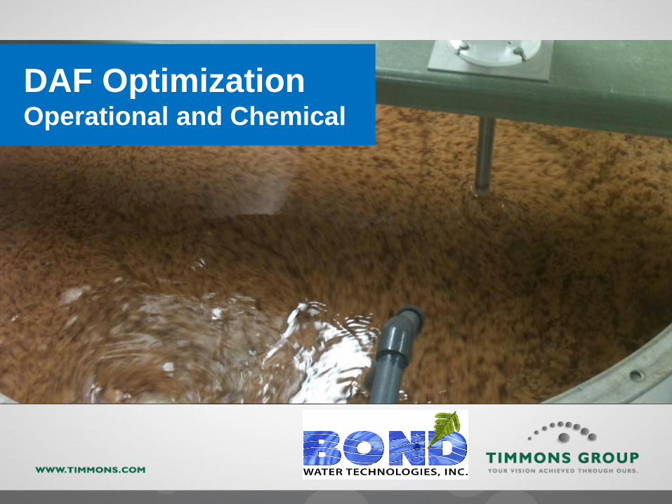
DAF Optimization Operational and Chemical

26
Bond Water Case Study
Wastewater Treatment Case Study:
Project Nemo
FOG (Fats, Oils & Greases), TSS, BOD Removal

27
Case Study Background
FOG, TSS and BOD can be one of themost challenging aspects for a plant tomaintain compliance with theirdischarge permit.
A major seafood processing plant wasfacing pressure from both the city andsanitation district for violating theirpermit on FOG, TSS and BOD in additionto causing major pump station issues forthe municipality. The customer had aDAF system in place that was designedyears ago for lower flows and FOG/TSS.
28
Case Study Background – cont.
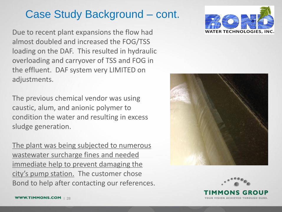
Due to recent plant expansions the flow had almost doubled and increased the FOG/TSS loading on the DAF. This resulted in hydraulic overloading and carryover of TSS and FOG in the effluent. DAF system very LIMITED on adjustments.
The previous chemical vendor was using caustic, alum, and anionic polymer to condition the water and resulting in excess sludge generation.
The plant was being subjected to numerous wastewater surcharge fines and needed immediate help to prevent damaging the city’s pump station. The customer chose Bond to help after contacting our references.
29
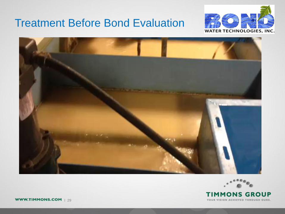
Treatment Before Bond Evaluation
30
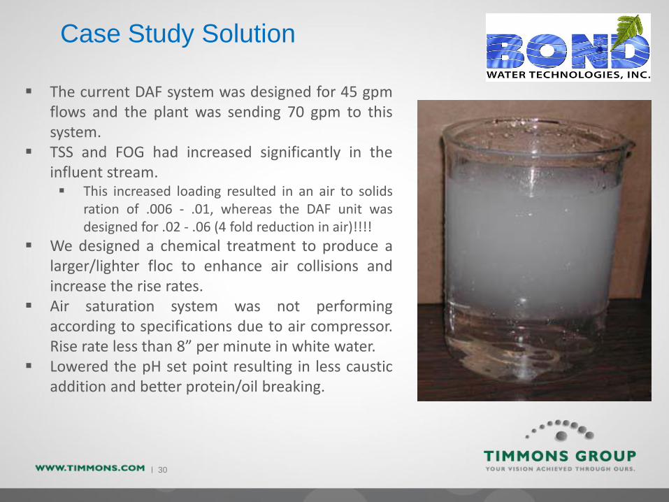
Case Study Solution
The current DAF system was designed for 45 gpmflows and the plant was sending 70 gpm to thissystem.
TSS and FOG had increased significantly in theinfluent stream. This increased loading resulted in an air to solids
ration of .006 - .01, whereas the DAF unit wasdesigned for .02 - .06 (4 fold reduction in air)!!!!
We designed a chemical treatment to produce alarger/lighter floc to enhance air collisions andincrease the rise rates.
Air saturation system was not performingaccording to specifications due to air compressor.Rise rate less than 8” per minute in white water.
Lowered the pH set point resulting in less causticaddition and better protein/oil breaking.

31
Case Study Solution - continued
Some minor piping changes were made to allowfor longer air to solids contact time, thusincreasing their chances of collision andfloatation.
“In-house” modifications had been made to theDAF unit resulting in short cycling of the system.Always review the original equipmentlayout/specifications!!!!
Percent solids in sludge was running at <1% andresulting in extremely high disposal cost.Adjustments to varying the rake speed via leveldetection and modifications to the sludge tank toinclude decanting valves and dewatering boxeshave increased this number to 10%.

32
Case Study Results
The new treatment system and modifications haveallowed the customer to stay under permit for FOGand TSS. In addition the city has not had any furtherissues with their pump station. We are estimating a
savings of $25K per year in chemical and surchargereductions. Sludge disposal costs have been
decreased by $65K per year. Bond’s continued valueplan for servicing the customer includes:
Routine service visits to monitoring chemicalusage and system KPI’s
Routine service reports covering systemperformance and chemical usage/cost
Routine Jar Testing Routine Operator Training Continual Improvement Projects
https://www.youtube.com/watch?v=kuwClARJZUY

33
Treatment With Bond Water

34
Questions?