distress survey manual
TRANSCRIPT

PAVEMENT DISTRESS SURVEY MANUAL
PAVEMENT SERVICES UNIT
REVISED JUNE 2010

ODOT Distress Survey Manual Revised June 2010
2
OREGON DEPARTMENT OF TRANSPORTATION
Distress Survey Manual
INTRODUCTION • This manual in conjunction with the SHRP Distress Identification Manual
for the Long-Term Pavement Performance Project (SHRP-P-338) outlines the procedure for conducting distress surveys. The purpose of the distress surveys is to identify and quantify the amount and severity of surface distress in a given segment of pavement. The results of the distress survey are used along with other measured pavement characteristics to establish a condition rating for the roadway segment.
• The Oregon State Highway System is currently composed of three primary
surface types; Asphalt Concrete (AC), Jointed Portland Cement Concrete Pavement (JCP), and Continuously Reinforced Portland Cement Concrete Pavement (CRCP). The distress types and procedures for rating each of these pavement types are presented in this manual.
• The main use of this manual is to perform detailed distress rating for
National Highway System (NHS) and other State Highways where appropriate to assess pavement conditions of the state highway network. The distress survey is intended primarily to characterize type and extent of pavement distress, but does not attempt to determine the cause of distress and appropriate corrective treatments. Although it may be a useful resource to other pavement related uses this manual is intended primarily for Pavement Management purposes.
SURVEY PROCEDURE
• Two-person crews trained in distress identification procedures will conduct condition surveys. Training will include proper distress identification using standardized sections of the State Highway System. These standardized sections will include examples of each of the three pavement types. For a given pavement type, the standardized sections will include typical examples of each type of distress.
• The condition survey will be accomplished via a”side window” survey from
a slow-moving vehicle operating on the adjacent shoulder. If conditions do not permit the safe operation of a vehicle along the shoulder, then the crew will either skip the segment or conduct the survey on foot being careful to not endanger themselves or the motoring public.

ODOT Distress Survey Manual Revised June 2010
3
• The condition survey may also be accomplished via a Pavement Condition Data Collection Vehicle (service tool equipped with computer, sensor, and video equipment designed to efficiently collect data and video images of the roadway and pavement surface). Data obtained by this vehicle is reviewed later in the office to generate a condition score.
• The highway will be rated in 0.1-mile increments. The distresses will be
recorded for each segment rated. The distress will be identified according to the descriptions provided in this manual.
• The following is a brief summary of the distress survey procedure:
• Begin at the appropriate milepoint marker. • Select the appropriate data entry screen or survey form (AC, JCP,
or CRCP). • Complete the section description information. • Survey the 0.1-mile segment. • Record information on the computer or survey form. • Return to step one and repeat the process.
When recording the survey data, note any unusual conditions in the comment section. Also note, but do not rate, long bridge decks, which fall within the section. Frequently, only partial miles will be rated because of construction activity, a bridge deck, or for safety reasons. In the event one or more 0.1-mile segments are not rated within a given mile, place an "N” in the appropriate field to indicate that the segment was not rated. Also note in the remarks field the reason why the segment was not rated.

ODOT Distress Survey Manual Revised June 2010
4
DISTRESS SURVEY MANUAL
SECTION 1 ASPHALT CONCRETE (AC)
PAVEMENTS The evaluation of asphalt pavements will be completed by rating the distress in the pavement according to the SHRP descriptions and severity levels as summarized below.
DISTRESS TYPES
Rutting Fatigue Cracking
Longitudinal Cracking Transverse Cracking
Block Cracking Patches Potholes Raveling Bleeding

ODOT Distress Survey Manual Revised June 2010
5
Summary of AC Pavement Distresses
Rutting
Zero 0” ≤ Rut < 1/4”
Low 1/4” ≤ Rut < 1/2”
Moderate 1/2” ≤ Rut < 3/4”
High Rut ≥ 3/4"
Fatigue Crack Severity
Low An area of cracks with no or only a few connecting cracks. Cracks are not spalled or sealed. No pumping is evident.
Moderate An area of interconnected cracks forming a complete pattern. Cracks may be slightly spalled. Cracks may be sealed. No pumping is evident.
High An area of moderately or severely spalled interconnected cracks forming a complete pattern. Pieces may move when subjected to traffic. Cracks may be sealed. Pumping may be evident.
Longitudinal Cracking Severity
Low A crack with a mean width of ≤ 0.25”; or a sealed crack with sealant material in good condition and a width that cannot be determined.
Moderate Any crack with a mean width > 0.25” and ≤ 0.75”; or any crack with a mean width < 0.75 in and adjacent low severity random cracking.
High Any crack with a mean width > 0.75”; or any crack with a mean width ≤ 0.75” and adjacent moderate to high severity random cracking.
Transverse and Block Crack Severity
Low An unsealed crack with a mean width of ≤ 0.25; or a sealed crack with sealant material in good condition and the width cannot be determined.
Moderate Any crack with a mean width > 0.25” and ≤ 0.75”; or any crack with a mean width < 0.75 in and adjacent low severity random cracking.
High Any crack with a mean width > 0.75”; or any crack with a mean width ≤ 0.75” and adjacent moderate to high severity random cracking.
Patching Severity
Low A good quality patch with a smooth ride. The patch has, at most, low severity distress of any type including rutting or deformation < 0.25”; pumping is not evident.
Moderate The patch has moderate severity distress of any type or rutting or deformation from 0.25” to 0.5”; pumping may be evident. Ride quality is good to fair.
High The patch has high severity distress of any type or rutting or deformation > 0.5”; pumping may be evident. All hand patches or patched potholes are rated as high severity patches.
Pothole Severity
Low < 1" deep (Delamination of patch or seal coat)
Moderate ≥ 1" & < 2" deep (Remains within top lift of wearing course.) High ≥ 2" deep (Extends beyond top lift of wearing course.)
Raveling Severity
Low The aggregate has worn away resulting in ≥ 25% to < 50% aggregate loss in a 1’ wide longitudinal strip of pavement surface. Loss of chip seal rock should be rated as raveling, but this is the maximum severity for chip sealed surfaces.
Moderate Surface texture is noticeably rough and/or pitted with ≥ 50% to < 75 % aggregate loss in a 1’ wide longitudinal strip of pavement surface. A nearly continuous strip of aggregate loss 3” - 6” wide may be present. Loose particles may be present outside the traffic area.
High Surface texture is very rough and/or pitted with ≥ 75% aggregate loss in a 1’ wide longitudinal strip of pavement surface. Flat bottom potholes may be present where complete loss of aggregate has occurred.
Bleeding
Y or N Bleeding is present if multiple (2 or more) areas of 25 ft2 or larger patches are noted.

ODOT Distress Survey Manual Revised June 2010
6
RUTTING
AC – JCP – CRCP Rutting is a longitudinal surface depression in the wheel path caused by permanent deformation (AC only) or the wearing away of the pavement surface. Rut depth is measured in both wheel paths by a 5-point laser system mounted on the profilometer. This measurement is performed separate from the manual distress survey. The rut depth will be categorized as zero, low, moderate, or high according to the following criteria:
Identification
Longitudinal surface depression in wheel path
Severity Level Zero = 0” ≤ Rut < 1/4” Low = 1/4” ≤ Rut < 1/2” Mod = 1/2” ≤ Rut < 3/4” High ≥ 3/4”
How to Measure
5-Point Laser System Ruts are measured with a 5 point laser system mounted on the front bumper of a Class 1 high speed Profilometer. The data is collected every 6-inches and then aggregated for every 10th mile. The average rut depth plus one standard deviation for each wheelpath is evaluated and the greater of the two measurements determines the rut severity.

ODOT Distress Survey Manual Revised June 2010
7
RUTTING
Low Rutting
Moderate Rutting
High Rutting

ODOT Distress Survey Manual Revised June 2010
8
FATIGUE CRACKING
Fatigue cracking, also known as alligator cracking, is single crack or a series of interconnected cracks caused by fatigue failure of the asphalt concrete.
Identification Fatigue cracking occurs in areas subjected to repeated traffic loading (wheel paths) but also maybe present anywhere in the lane due to traffic wander. A series of interconnected cracks characterizes early stages of development. It eventually develops into many-sided, sharp-angled pieces, usually less than 1 foot on the longest side. Characteristically has chicken wire/alligator pattern in later stages. Longitudinal cracks occurring in the wheel path are rated as fatigue.
Severity Levels Low - An area of cracks with no or only a few connecting cracks Cracks are not spalled or sealed No pumping is evident. Moderate - An area of interconnected cracks forming a complete pattern Cracks may be slightly spalled
Cracks may be sealed No pumping is evident. High - An area of moderately or severely spalled interconnected cracks forming
a complete pattern Pieces may move when subjected to traffic
Cracks may be sealed Pumping may be evident
How to Measure Visually estimate the linear feet of the wheel path affected. Record the linear feet at each severity level. Maximum quantity - 1,000 ft per 0.1-mile. Per new HPMS requirements, also record the area of fatigue cracking in square feet at each severity level. A single longitudinal fatigue crack should be considered to have a width of 0.5’ in the area calculation. If different severity levels exist within an area that cannot easily be distinguished, use highest severity level.

ODOT Distress Survey Manual Revised June 2010
9
LOW SEVERITY FATIGUE CRACKING
Picture #1 - Longitudinal cracks occurring in the wheel path (red arrow). Picture #2 - The main crack is sealed but there are several small cracks branching off it (red
arrow). Picture #3 - There are 2 cracks in the right wheel path that interconnect in several places (red
arrow), but a pattern has not formed. Picture #4 - This picture contains low and moderate severity fatigue cracking. The left wheel
path contains the low severity cracking. The cracks are interconnected (red arrows) but haven’t formed a pattern as seen in the right wheel path (red circle).
Picture #1 Picture #2
Picture #3 Picture #4

ODOT Distress Survey Manual Revised June 2010
10
MODERATE SEVERITY FATIGUE CRACKING
Picture #1 - Some of the fatigue cracks have been sealed, but the cracks are forming a pattern (red circle) making this moderate severity fatigue.
Picture #2 - This is predominantly moderate severity fatigue therefore it should be rated as moderate severity although portions of it are borderline high severity due to spalled edges (red arrow).
Picture #3 - A majority of these cracks are not spalled. Picture #4 - This picture is a close up of spalled fatigue crack edges. Some of the cracks are
slightly spalled (red arrow). All of these pictures display a cracking pattern (alligator).
Picture #1 Picture #2
Picture #3 Picture #4

ODOT Distress Survey Manual Revised June 2010
11
HIGH SEVERITY FATIGUE CRACKING
Picture #1 - Sections of the fatigued area are missing or have been patched (both circled in red). These distresses should also be rated as potholes.
Picture #2 - Sections of the fatigued area are missing (circled in red) and the crack edges are severely spalled (red arrow). These distresses should also be rated as potholes.
Picture #3 - The crack edges are spalled and a depression can be seen in the right wheel path. Picture #4 - This picture is a close up of spalled fatigue crack edges (red arrow). All of these pictures display a cracking pattern (alligator).
Picture #1 Picture #2
Picture #3 Picture #4

ODOT Distress Survey Manual Revised June 2010
12
LONGITUDINAL CRACKING Longitudinal cracks are cracks that are predominantly parallel to the pavement’s centerline. Only longitudinal cracks that are not in a wheel path should be recorded as this form of distress.
Identification
Cracks predominantly parallel to pavement centerline and generally outside the wheel path. Majority of cracks are within 1’ of the skip stripe or fog stripe / edge of pavement or within 1’ of the middle of the lane. Cracks may meander into the wheel path, but generally stays out of the wheel path. Longitudinal cracks which occur in the wheel path should be rated as low severity fatigue cracking.
Severity Levels Low - A crack with a mean width of ≤ 0.25”; or a sealed crack with sealant material in good condition and a width that cannot be determined. Moderate - Any crack with a mean width > 0.25” and ≤ 0.75”; or any crack with a mean width < 0.75 in and adjacent low severity random cracking. High - Any crack with a mean width > 0.75”; or any crack with a mean width ≤ 0.75” and adjacent moderate to high severity random cracking.
How to measure Record the linear feet at each severity level. The maximum length longitudinal cracking is 1,500 linear feet per 0.1-mile section. If questionable whether longitudinal or fatigue cracking, record as fatigue.
Left side of Lane
Center
Right Side
Wheel Paths
Longitudinal cracking

ODOT Distress Survey Manual Revised June 2010
13
LONGITUDINAL CRACKING
Low Severity Low Severity
Moderate Severity Low severity with adjacent random cracking becomes Moderate Severity
High Severity High Severity

ODOT Distress Survey Manual Revised June 2010
14
TRANSVERSE CRACKING
Transverse cracks are predominantly perpendicular to the pavement centerline, and may extend all or part way across the travel lane. The amount of transverse cracking will be measured by counting the actual number of cracks that occur in the travel lane being rated.
Identification Transverse cracks predominantly perpendicular to pavement centerline. Cracks must extend at least half way across the travel lane before being counted.
Severity Levels Low - An unsealed crack with a mean width of ≤ 0.25; or a sealed crack with sealant material in good condition and the width cannot be determined. Moderate - Any crack with a mean width > 0.25” and ≤ 0.75”; or any crack with a mean width < 0.75 in and adjacent low severity random cracking. High - Any crack with a mean width > 0.75”; or any crack with a mean width ≤ 0.75” and adjacent moderate to high severity random cracking.
How to Measure Record number of transverse cracks at each severity level. Maximum number of Transverse Cracks per 0.10-mile is 44. Per new HPMS requirements, also record the length of transverse cracking in feet at each severity level. Rate entire transverse crack at the highest severity level present (must be present over 10% of crack).

ODOT Distress Survey Manual Revised June 2010
15
TRANSVERSE CRACKING
Low Severity
High Severity High Severity
Low Severity
Moderate Severity
Moderate Severity

ODOT Distress Survey Manual Revised June 2010
16
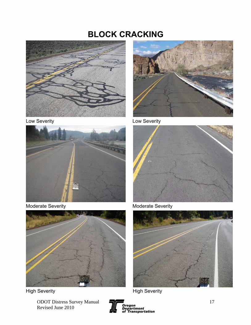
BLOCK CRACKING
Block cracking is a distress where cracks divide the pavement surface into approximately rectangular pieces. These pieces are typically 1 to 100 square feet. Block cracking, unlike fatigue cracking, will typically occur throughout the pavement width, not just in the wheel paths.
Identification Block cracking is a pattern of cracks that divide the pavement into approximately rectangular pieces or blocks. Blocks range in size from approximately 1 ft2 to 100 ft2.
Severity Levels Low - Cracks with a mean width of ≤ 0.25; or sealed cracks with sealant material in good condition and the width cannot be determined. Moderate - Cracks with a mean width > 0.25” and ≤ 0.75”; or any crack with a mean width < 0.75 in and adjacent low severity random cracking. High - Cracks with a mean width > 0.75”; or any crack with a mean width ≤ 0.75” and adjacent moderate to high severity random cracking.
How to Measure Record the square feet of affected area at each severity level. The maximum area of Block cracking is 6,000 ft2 per 0.10-mile. Note: An occurrence should be at least 50 feet long before rating as block
cracking.
ODOT Distress Survey Manual Revised June 2010
17
BLOCK CRACKING
Low Severity Low Severity
Moderate Severity Moderate Severity
High Severity High Severity
ODOT Distress Survey Manual Revised June 2010
18
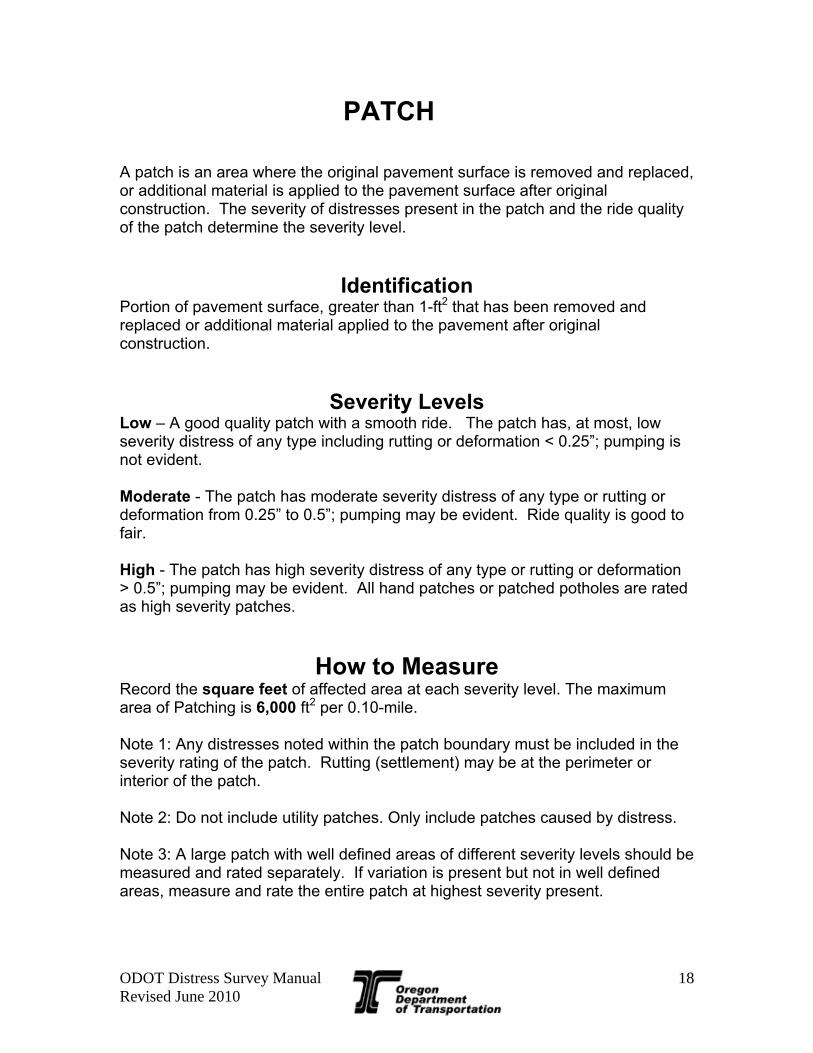
PATCH A patch is an area where the original pavement surface is removed and replaced, or additional material is applied to the pavement surface after original construction. The severity of distresses present in the patch and the ride quality of the patch determine the severity level.
Identification Portion of pavement surface, greater than 1-ft2 that has been removed and replaced or additional material applied to the pavement after original construction.
Severity Levels Low – A good quality patch with a smooth ride. The patch has, at most, low severity distress of any type including rutting or deformation < 0.25”; pumping is not evident. Moderate - The patch has moderate severity distress of any type or rutting or deformation from 0.25” to 0.5”; pumping may be evident. Ride quality is good to fair. High - The patch has high severity distress of any type or rutting or deformation > 0.5”; pumping may be evident. All hand patches or patched potholes are rated as high severity patches.
How to Measure Record the square feet of affected area at each severity level. The maximum area of Patching is 6,000 ft2 per 0.10-mile. Note 1: Any distresses noted within the patch boundary must be included in the severity rating of the patch. Rutting (settlement) may be at the perimeter or interior of the patch. Note 2: Do not include utility patches. Only include patches caused by distress. Note 3: A large patch with well defined areas of different severity levels should be measured and rated separately. If variation is present but not in well defined areas, measure and rate the entire patch at highest severity present.

ODOT Distress Survey Manual Revised June 2010
19
LOW SEVERITY PATCHING
Picture #1 - This is a good quality smooth wheel path patch with no distress. Picture #2 - This is a good quality smooth blade patch with no distress. Picture #3 - This is a good quality smooth wheel path patch with no distresses in the left wheel
path and low severity wheel path cracking on the right (red arrow). Both patches would be rated as low severity. The wheel path cracking quantity is also rated in addition to the patching distress.
Picture #4 - This is a good quality smooth wheel path patch with low severity wheel path cracking (red arrow). The wheel path cracking quantity is also rated in addition to the patching distress.
cture #2
Picture #3 Picture #4
Picture #1 Pi

ODOT Distress Survey Manual Revised June 2010
20
MODERATE SEVERITY PATCHING
Picture #1 - This is a wheel path patch with moderate severity fatigue (red arrow). If this patch had no or low severity distress it would be rated as a low severity patch. Further in the lane is a newer low severity blade patch (blue arrow)
Picture #2 - This is a blade patch with moderate severity fatigue (red arrow). Picture #3 - This is a blade patch with moderate severity fatigue (red arrow). Picture #4 - This is a wheel path patch with fair quality ride.
Picture #1 Picture #2
Picture #3 Picture #4

ODOT Distress Survey Manual Revised June 2010
21
HIGH SEVERITY PATCHING
Picture #1 - This is an inlayed wheel path patch with high severity fatigue (red arrow). Picture #2- All of the wheel paths in this picture have been patched. The patch edges are
shown with red arrows. The high severity fatigue drives these patches severity to high. Picture #3 - This is a hand patch (all hand patches are considered high severity). Picture #4 - The patch on the left (red arrow) has > 0.5” deformation (red circle) and has a
jagged edge. This patch on the right (blue arrow) is a low severity patch
Picture #1 Picture #2
Picture #3 Picture #4

ODOT Distress Survey Manual Revised June 2010
22
POTHOLE A pothole is a shallow or deep hole in the pavement surface resulting from loss of pavement surfacing material. Prior to 2010, potholes and patches were rated together. Starting with the 2010 rating, they shall be rated separately.
Identification Bowl-shaped holes of various sizes in the pavement surface. Minimum plan dimension is 6”.
Severity Levels Low - < 1” deep (Typically delamination of patch or seal coat) Moderate - ≥ 1” & < 2” deep (Remains within top lift of asphalt wearing course) High - ≥ 2” deep (Extends beyond top lift of asphalt wearing course)
How to Measure Record the number of potholes at each severity level, up to a maximum of 44 per 0.10 of a mile. A long pothole or string of potholes greater than 12’ in length shall be counted as separate potholes. For example, a 40’ continuous string of potholes would be counted as 4 potholes.

ODOT Distress Survey Manual Revised June 2010
23
POTHOLE
Low Severity Low Severity
Moderate Severity Moderate Severity
High Severity High Severity

ODOT Distress Survey Manual Revised June 2010
24
RAVELING Raveling is the wearing away of the pavement surface caused by the dislodging of aggregate particles. It is a progressive disintegration from the surface downward, usually as the result of traffic action. The severity of raveling is based on the estimated percentage of aggregate loss in a 1’ wide longitudinal strip of pavement surface as described below. The quantity of raveling will be estimated based on the linear feet of raveling occurring in the inside wheel path, outside wheel path, and between the wheel paths.
Identification Raveling can be identified by a roughened or pitted texture on the pavement surface. Mechanical abrasion from tire chains, studs, snowplows, or dragging equipment which significantly roughens up the texture should be rated as raveling. Studded tire rutting which does not roughen up the texture significantly should not be rated as raveling. Raveling tends to be most often found in the wheel paths, but can be elsewhere on the pavement surface.
Severity Level For all surface types, raveling is not rated if less than 25% of the surface in a given 1’ wide strip is affected. NOTE Chip Seals are normally rough textured - only rate as low severity raveling if there is ≥ 25% aggregate loss present in a 1’ wide strip. Low - The aggregate has worn away resulting in ≥ 25% to < 50% aggregate loss in a 1’ wide longitudinal strip of pavement surface. Loss of chip seal rock should be rated as raveling, but this is the maximum severity for chip sealed surfaces. Moderate - Surface texture is noticeably rough and/or pitted with ≥ 50% to < 75 % aggregate loss in a 1’ wide longitudinal strip of pavement surface. A nearly continuous strip of aggregate loss 3” - 6” wide may be present. Loose particles may be present outside the traffic area. High - Surface texture is very rough and/or pitted with ≥ 75% aggregate loss in a 1’ wide longitudinal strip of pavement surface. Flat bottom potholes may be present where complete loss of aggregate has occurred.
How to Measure Record linear feet of each severity level for each path - inside, outside, and between wheel paths. Maximum of 500 ft per path and 1,500 ft per 0.1 mile. If raveling covers entire area count as if there were 3 adjacent paths.
1’ Wide

ODOT Distress Survey Manual Revised June 2010
25
RAVELING
No raveling (open graded surface) No raveling (open graded surface)
Low in wheel paths (open graded surface) Low - same as left (close up)
Moderate in wheel paths (open graded surf.) Moderate - same as left (close up)

ODOT Distress Survey Manual Revised June 2010
26
RAVELING
Moderate in left wheel path, low in right Moderate in left wheel path, low between wheel paths
High High
High (close up) High (with potholes)

ODOT Distress Survey Manual Revised June 2010
27
BLEEDING Bleeding is indicated by the excess bituminous material on the pavement surface, which creates a shiny, glass-like reflective surface. Bleeding is not rated by severity level, but should be recorded when it is severe enough to cause a reduction in skid resistance. A segment is considered to have measurable bleeding if it has multiple areas ≥ 25 square feet of bleeding. Bleeding will simply be recorded as either existing or not existing for each 0.1-mile segment.
Identification Excess bituminous binder on pavement surface, and may create a shiny, glass-like, reflective surface that may be tacky to the touch. Usually found in the wheel paths. Note: Prevention maintenance treatments (slurry seals, chip seals, fog seals, etc.) sometimes exhibit bleeding characteristics. These occurrences should be noted, but not rates as bleeding
Severity Levels Bleeding is present if multiple (2 or more) areas of 25 ft2 or larger.
How to Measure Recorded as either existing or not existing (Yes/No)

ODOT Distress Survey Manual Revised June 2010
28
BLEEDING

ODOT Distress Survey Manual Revised June 2010
29
DISTRESS SURVEY MANUAL
SECTION 2 JOINTED CONCRETE PAVEMENTS
(JCP) The evaluation of jointed concrete pavements will be completed by rating the distress in the pavement according to the SHRP descriptions and severity levels as summarized below.
DISTRESS TYPES
Rutting (See AC Pavement Section) Corner Crack Corner Break
Longitudinal Cracking Transverse Cracking
Shattered Slab Patch Condition Joint Condition
Faulting (measure per AASHTO R36-04 – not in this manual)
Per the new 2010 HPMS requirements, the percentage of slabs with fatigue cracking must be recorded. For this requirement, record the total number of all slabs in the 0.1 mile segment. Also record the number of fatigue cracked slabs in the segment. A fatigue cracked slab is one with one or more of the following distresses:
Corner Crack Corner Break Shattered Slab
A slab with more than one of the distresses listed above is counted as only 1 slab. Use the highest severity of any of the distresses present to determine the overall severity of the cracked slab.

ODOT Distress Survey Manual Revised June 2010
30
Summary of JCP Pavement Distresses
Rutting
Zero 0” ≤ Rut < 1/4”
Low 1/4” ≤ Rut < 1/2”
Moderate 1/2” ≤ Rut < 3/4”
High Rut ≥ 3/4"
Corner Crack
Low Crack widths < 0.125”, no spalling, and no measurable faulting; or well sealed and with a width that cannot be determined.
Moderate Crack widths > 0.125” and < 0.5”; or with spalling < 3”; or faulting up to 0.5”. High Crack widths > 0.5”; or with spalling > 3”; or faulting > 0.5”.
Corner Break
Low Crack is not spalled for more than 10 percent of the length of the crack; there is no measurable faulting; and the corner piece is not broken into two or more pieces and has no loss of material and no patching.
Moderate Crack is spalled at low severity (< 3”) for more than 10 percent of its total length; or faulting of crack or joint is < 0.5”; and the corner piece is not broken into two or more pieces.
High Crack is spalled at moderate (> 3” and <6”) to high severity (> 6” and <10”) for more than 10 percent of its total length; or faulting of the crack or joint is ≥ 0.5”; or the corner piece is broken into two or more pieces or contains patch material.
Longitudinal Cracking
Low Crack widths < 0.125”, no spalling, and no measurable faulting; or well sealed and with a width that cannot be determined.
Moderate Crack widths > 0.125” and < 0.5”; or with spalling < 3”; or faulting up to 0.5”. High Crack widths > 0.5”; or with spalling > 3”; or faulting > 0.5”.
Transverse Cracking
Low Crack width < 0.125 inches, and no spalling, and no measurable faulting; or well-sealed and width cannot be determined.
Moderate Crack widths ≥ 0.125 inches and < 0.25 inches; or with spalling < 3 inches; or faulting up to 0.25 inches. High Crack widths ≥ 0.25 inches; or with spalling ≥ 3 inches; or faulting ≥ 0.25 inches.
Shattered Slab
Low Slab is broken into 3 pieces. The cracks describing the broken sections are not spalled or are spalled for < 10 % of the length of the crack; no measurable faulting.
Moderate Slab is broken into 4 pieces; or the cracks describing the broken sections are spalled at low severity (< 3”) for > 10% of its total length; or faulting is < 0.5”.
High Slab is broken into 5 or more pieces; or the cracks describing the broken sections are spalled > 3” for >10 % of its total length; or faulting is ≥ 0.5”.
Patch Condition
Low Patch has at most low severity distress of any type; and no measurable faulting or settlement; pumping is not evident.
Moderate Patch has moderate severity distress of any type; or faulting or settlement to 0.25 inches; pumping is not evident.
High Patch has a high severity distress of any type; or faulting or settlement ≥ 0.25 inches; pumping may be evident. Also includes patches that are not made with concrete materials.
Joint Condition Low Joint is in good condition and seal is in good condition. Moderate Joint is slightly spalled with seal in good condition or joint is in good condition with seal in poor condition. High Joint is badly spalled or joint is slightly spalled with seal in poor condition.

ODOT Distress Survey Manual Revised June 2010
31
CORNER CRACKING Corner cracks are cracks of any length that intersect at least one transverse joint and are predominantly parallel to the pavement centerline. Corner crack severity is based on crack width, spalling or faulting.
Identification A crack, predominantly parallel to the pavement centerline, which intersects at least one transverse joint and radiates into the panel. These cracks must be located laterally in the wheel path. For this purpose, the wheel path is from 1’ inside the lane or shoulder joint to 1' from the middle of the lane. Corner cracks that intersect transverse cracks will be rated as corner breaks and not as corner cracks.
Severity Levels Low – Crack widths < 0.125”, no spalling, and no measurable faulting; or well sealed and with a width that cannot be determined. Moderate – Crack widths > 0.125” and < 0.5”; or with spalling < 3”; or faulting up to 0.5”. High – Crack widths > 0.5”; or with spalling > 3”; or faulting > 0.5”.
How to Measure Record the number of corner cracks at each severity level (Total 32 max per 0.1 mile The length of corner cracks should also be measured and recorded as longitudinal cracks. A longitudinal crack that intersects both transverse joints should be rated and recorded as 2 corner cracks, plus a longitudinal crack. Cracks that occur between the wheel paths should be rated and recorded as longitudinal cracking only, not corner cracking.

ODOT Distress Survey Manual Revised June 2010
32
CORNER CRACKING
Low - Corner crack is tight and has no Moderate - Corner crack has spalling less spalling or faulting. than 3” wide. Moderate - Corner crack has spalling less Moderate - Corner crack width is over 1/8” than 3” wide. but less than ½” wide. Moderate - Corner crack has spalling less Moderate - Corner crack has spalling less than 3” wide. than 3” wide.

ODOT Distress Survey Manual Revised June 2010
33
CORNER BREAK A corner break is the separation of a corner portion of concrete from the rest of the PCC slab. Corner breaks occur when a corner crack is intersected by a transverse crack or when a diagonal crack extends across the corner of a slab. Corner break severity is based on spalling, faulting, or number of broken pieces, not crack width.
Identification A crack which separates the slab and intersects the adjacent transverse and longitudinal joints, describing an approximate 45 degree angle with the direction of traffic. Not included are cracks that are within one foot of the edge and less than 1 foot long.
Severity Levels Low – Crack is not spalled for more than 10 percent of the length of the crack; there is no measurable faulting; and the corner piece is not broken into two or more pieces and has no loss of material and no patching. Moderate – Crack is spalled at low severity (< 3”) for more than 10 percent of its total length; or faulting of crack or joint is < 0.5”; and the corner piece is not broken into two or more pieces. High – Crack is spalled at moderate (> 3” and <6”) to high severity (> 6” and <10”) for more than 10 percent of its total length; or faulting of the crack or joint is ≥ 0.5”; or the corner piece is broken into two or more pieces or contains patch material.
How to Measure Record the number of corner breaks at each severity level (Total 32 max)

ODOT Distress Survey Manual Revised June 2010
34
CORNER BREAK
Low - Corner Break Moderate - Crack has low severity (<3” wide) spalling for > 10% of length.
High - Corner break broken into two or more pieces.
High - Faulted over 1/2”.
Not a corner break because less than 1’ from transverse joint.

ODOT Distress Survey Manual Revised June 2010
35
LONGITUDINAL CRACKS Longitudinal cracks are cracks that are predominantly parallel to the pavement centerline. Longitudinal cracks may occur laterally anywhere within the rated lane. The crack severity is based on width, spalling, and faulting.
Identification Cracks that are predominately parallel to the pavement centerline. Longitudinal cracks that intersect transverse cracks will be rated as corner breaks and not as longitudinal cracks.
Severity Levels Low – Crack widths < 0.125”, no spalling, and no measurable faulting; or well sealed and with a width that cannot be determined. Moderate – Crack widths > 0.125” and < 0.5”; or with spalling < 3”; or faulting up to 0.5”. High – Crack widths > 0.5”; or with spalling > 3”; or faulting > 0.5”.
How to Measure Record the linear feet in each severity level (1500 ft Maximum per 0.1 mile segment). A longitudinal crack that intersects a transverse joint should also be rated and recorded as a corner crack for each transverse joint intersected. Cracks that occur outside the wheel paths should be rated and recorded as longitudinal cracking only, not corner cracking.

ODOT Distress Survey Manual Revised June 2010
36
LONGITUDINAL CRACKS
Low Severity Up Close picture of the crack
Moderate Severity Up Close picture of the crack
High Severity Up Close picture of the crack

ODOT Distress Survey Manual Revised June 2010
37
TRANSVERSE CRACK Transverse cracks are cracks that are predominantly perpendicular to the pavement centerline. These cracks extend all or part way across the travel lane. Transverse crack severity is based on crack width, spalling and faulting. The amount of transverse cracking will be measured by counting the actual number of cracks that occur in the travel lane being rated.
Identification Cracks that are perpendicular to the pavement centerline.
Severity Levels Low – Crack width < 0.125 inches, and no spalling, and no measurable faulting; or well-sealed and width cannot be determined. Moderate – Crack widths ≥ 0.125 inches and < 0.25 inches; or with spalling < 3 inches; or faulting up to 0.25 inches. High – Crack widths ≥ 0.25 inches; or with spalling ≥ 3 inches; or faulting ≥ 0.25 inches.
How to Measure
Record the number of cracks at each severity (Total 44 maximum). Rate the entire transverse crack at the highest severity level present for at least 10% of the total length of the crack. Cracks should extend at least half way across the travel lane before being counted.

ODOT Distress Survey Manual Revised June 2010
38
TRANSVERSE CRACK
Low - Transverse crack width < 0.125” No faulting or spalling.
Moderate - Transverse crack has spalling.
High - Transverse crack width is over 1/4”

ODOT Distress Survey Manual Revised June 2010
39
SHATTERED SLAB A shattered slab is a concrete slab that is broken into three or more pieces. Slabs that are divided solely by transverse cracks are not included. Corner breaks are also not included. The severity of a shattered slab is determined by the number of pieces the slab is broken into combined with the severity of spalling and faulting exhibited. The quantity of shattered slabs will be measured by counting the number that occurs in each 0.1-mile segment.
Identification A concrete slab that is broken into three or more pieces. Do not include corner breaks when counting broken slab sections. Also do not include slab sections that are divided by one or more transverse cracks.
Severity Levels Low – Slab is broken into 3 pieces. The cracks describing the broken sections are not spalled or are spalled for <10 % of the length of the crack; no measurable faulting. Moderate – Slab is broken into 4 pieces; or the cracks describing the broken sections are spalled at low severity (< 3”) for >10% of its total length; or faulting is < 0.5”. High – Slab is broken into 5 or more pieces; or the cracks describing the broken sections are spalled > 3” for >10 % of its total length; or faulting is ≥ 0.5”.
How to Measure
Record the number of shattered slabs at each severity level (Total 32 max).

ODOT Distress Survey Manual Revised June 2010
40
SHATTERED SLAB
Low - Slab broken into three pieces and no spalling exists.
Moderate - Slab broken into four sections and no spalling or faulting exists.
High - broken into five or more pieces.
Not a shattered slab. Slab broken into three sections by transverse cracks only. This is three T-cracks.

ODOT Distress Survey Manual Revised June 2010
41
PATCH CONDITION A patch is an area where the original pavement has been removed and replaced, or additional material applied to the pavement after original construction. If patch material is non-concrete, the patch will be rated as high severity. The patch severity is based on distresses present in the patch or faulting. The amount of patching will be measured by estimating the square feet of the rated lane that is patched.
Identification A portion or all of the original concrete slab that has been removed and replaced, or additional material applied to the pavement after original construction.
Severity Levels Low – Patch has at most low severity distress of any type; and no measurable faulting or settlement; pumping is not evident. Moderate – Patch has moderate severity distress of any type; or faulting or settlement to 0.25 inches; pumping is not evident. High – Patch has a high severity distress of any type; or faulting or settlement ≥ 0.25 inches; pumping may be evident. Also includes patches that are not made with concrete materials.
How to Measure Record the square feet at each severity level (6,000 square feet maximum).
ODOT Distress Survey Manual Revised June 2010
42
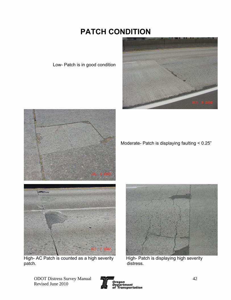
PATCH CONDITION Low- Patch is in good condition
Moderate- Patch is displaying faulting < 0.25”
High- AC Patch is counted as a high severity High- Patch is displaying high severity patch. distress.

ODOT Distress Survey Manual Revised June 2010
43
JOINT CONDITION
Rating Rating is based on a combination of the joint and joint seal condition. The condition of the transverse, lane, and shoulder joints will be rated separately based on the average condition of the joints in each segment, as follows:
Severity Level Low - Joint is in good condition and seal is in good condition. Mod - Joint is slightly spalled with seal in good condition or joint is in good condition with seal in poor condition. High - Joint is badly spalled or joint is slightly spalled with seal in poor condition.

ODOT Distress Survey Manual Revised June 2010
44
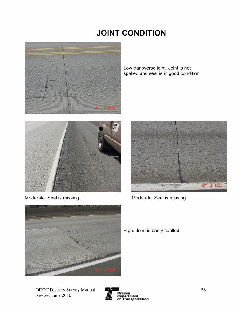
JOINT CONDITION
Moderate- Seal is missing. Moderate- Seal is missing.
Low - transverse joint. Joint is not spalled and seal is in good condition.
High - Joint is badly spalled.

ODOT Distress Survey Manual Revised June 2010
45
DISTRESS SURVEY MANUAL
SECTION 3 CONTINUIOUSLY REINFORCED
CONCRETE PAVEMENT (CRCP)
The evaluation of continuously reinforced concrete pavements will be completed by rating the distress in the pavement according to the SHRP descriptions and severity levels as summarized below.
DISTRESS TYPES
Rutting (See AC Pavement Section) Longitudinal Cracking Transverse Cracking
Punchouts Patches
Joint Condition

ODOT Distress Survey Manual Revised June 2010
46
Summary of CRCP Pavement Distresses
Rutting Zero 0” ≤ Rut < 1/4” Low 1/4” ≤ Rut < 1/2” Moderate 1/2” ≤ Rut < 3/4” High Rut ≥ 3/4" Longitudinal Cracking
Low
Non-wheel path longitudinal cracks with a width < 0.125”, no spalling, and no measurable faulting; or well sealed and with a width that cannot be determined. Low wheel path longitudinal cracks are bumped to moderate.
Moderate
Crack widths ≥ 0.125” and < 0.5”; or with spalling < 3”; or faulting up to 0.5”. Also includes low severity wheel path longitudinal cracks . Moderate wheel path longitudinal cracks are bumped to high.
High Crack widths ≥ 0.5”; or with spalling ≥ 3”; or faulting ≥ 0.5”. Also includes moderate severity wheel path longitudinal cracks.
Transverse Cracking Low Cracks that are not spalled or are spalled < 10% of the crack length. Moderate Cracks that are spalled along ≥ 10% and < 50% of the crack length. High Cracks that are spalled along ≥ 50% of the crack length. Punchouts
Low Longitudinal or transverse crack are spalling < 3” or faulting < 0.25”. At least two cracks defining the block must be spalled. Does not include "Y" cracks.
Moderate
Spalling ≥ 3” and < 6” or faulting ≥ 0.25 inches. Includes "Y" cracks that exhibit spalling, breakup and faulting in the branch portion of the "Y" along >10% (1' minimum) and <50% of crack length.
High
Spalling ≥ 6” or concrete within the punchout is punched down by ≥ 0.5” or is loose and moves under traffic. Includes "Y" cracks that exhibit high severity spalling, breakup and faulting in the branches of the "Y" along >50% of the crack length.
Patches
Low Patch has at most low severity distress of any type; and no measurable faulting or settlement; pumping is not evident.
Moderate Patch has moderate severity distress of any type; or faulting or settlement up to 0.25 inches; pumping is not evident.
High Patch has a high severity distress of any type; or faulting or settlement ≥ 0.25 inches at the perimeter of the patch; pumping may be evident.
Joint Condition Low Joint is in good condition and seal is in good condition.
Moderate Joint is slightly spalled with seal in good condition or joint is in good condition with seal in poor condition.
High Joint is badly spalled or joint is slightly spalled with seal in poor condition.

ODOT Distress Survey Manual Revised June 2010
47
LONGITUDINAL CRACKING Longitudinal cracks are cracks that are predominantly parallel to the pavement centerline. The crack severity is based on width, spalling, and faulting, and is adjusted for location laterally within the lane.
Identification Cracks that are predominately parallel to the pavement centerline. For CRCP, the severity level is "bumped" up to the next level if the crack is located in the wheel path, in accordance with the definition below. Wheel Path Longitudinal Cracks - Majority of crack is located laterally in the wheel path. For this purpose, the wheel path is from 1’ inside the lane or shoulder joint to 1' from the middle of the lane. Shape is typically linear and parallel to lane, although may be diagonal or crescent shaped. All wheel path related cracks are rated as either moderate or high severity Non-Wheel Path Longitudinal Cracks - Majority of crack is located out of wheel path as defined above. The crack may meander into wheel path but generally stays out of the wheel path.
Severity Levels Low – Non-wheel path longitudinal cracks with a width < 0.125”, no spalling, and no measurable faulting; or well sealed and with a width that cannot be determined. Low wheel path longitudinal cracks are bumped to moderate. Moderate – Crack widths ≥ 0.125” and < 0.5”; or with spalling < 3”; or faulting up to 0.5”. Also includes low severity wheel path longitudinal cracks. Moderate wheel path longitudinal cracks are bumped to high. High – Crack widths ≥ 0.5”; or with spalling ≥ 3”; or faulting ≥ 0.5”. Also includes moderate severity wheel path longitudinal cracks.
How to Measure Record the linear feet in each severity level. (1,500 feet maximum)

ODOT Distress Survey Manual Revised June 2010
49
WHEEL PATH LONGITUDINAL CRACKING
Moderate - Low sealed crack bumped to Moderate – Low crack bumped to moderate moderate.
High - Moderate crack bumped to high.
High - based on width. High - based on width and spalling.
.

ODOT Distress Survey Manual Revised June 2010
48
NON-WHEEL PATH LONGITUDINAL CRACKING
Low - Low based on sealant. Low- Crack is low based on width.
Moderate - Crack is moderate based on width.
High - High based on width and spalling.

ODOT Distress Survey Manual Revised June 2010
50
TRANSVERSE CRACK
Transverse cracking of continuously reinforced concrete pavement is normal and is not considered a form of distress. However, if the cracks open up, major deterioration may result. Transverse crack severity is rated based on the average crack condition in the 0.1-mile segment Also, at each milepoint marker, the average crack spacing is determined in a 100-foot section by dividing 100 by the number of cracks counted in the section.
Identification Cracks that are perpendicular to the pavement centerline
Severity Levels Low – Cracks that are not spalled or are spalled < 10% of the crack length. Moderate – Cracks that are spalled along ≥ 10% and < 50% of the crack length. High – Cracks that are spalled along ≥ 50% of the crack length.
How to Measure Measure once per mile at the mile point marker by counting the number of cracks within a 100-foot section. Record as a crack spacing (100/number of cracks). Severity is based upon average crack condition. All transverse cracks that intersect an imaginary longitudinal line at midlane, and propagate from the pavement edges, shall be counted as individual cracks. Cracks that do not cross midlane are not counted. EXAMPLE # 1 The DMI indicates the raters are at MP 240. The raters count the number and severity of the cracks for 100 feet. After traveling the 100 feet the raters have has gathered the following information: 17 Low severity cracks, of which 5 are "Y" cracks 20 Moderate severity cracks, of which 8 are "Y" cracks 3 High severity cracks, of which 1 is a "Y" crack. There are a total of 40 cracks (17 + 20 + 3 = 40). Recall that "Y" cracks are recorded as a single crack. The crack spacing is calculated as 100/40 = 3 (Nearest whole number). The average severity is moderate. Three is entered under the moderate spacing column for transverse crack severity EXAMPLE #2 The DMI indicates the raters are at MP 241. The following information is recorded in the 100-foot measurement interval. 1 Low severity cracks 4 Moderate severity cracks 15 High severity cracks The crack spacing is 100/20 = 5. The severity is high

ODOT Distress Survey Manual Revised June 2010
51
TRANSVERSE CRACK
Low - Spalling drives severity. This crack Low - Little spalling. has little to no spalling.
Three low cracks in a row. Moderate
Moderate next to a low. Close up of moderate next to a low.
High severity “T - Cracks” in CRCP are rare

ODOT Distress Survey Manual Revised June 2010
52
PUNCHOUT A punchout is the separation of a block of concrete from the rest of the CRCP formed by two closely spaced transverse cracks, a short longitudinal crack, and the edge of the pavement or longitudinal joint. As the cracks deteriorate, the steel ruptures and the block of concrete punches downward into the base and subbase. Punchouts will be rated as low, moderate, or high based on spalling or faulting. The quantity of punchouts will be measured by counting the number that occurs in each segment. If a punchout has been patched with asphalt, it should be rated as a high-severity punchout and not a patch, as the patch is only a temporary repair.
Description
A localized separation of a block of concrete from the rest of the PCC slab. Also includes "Y" cracks that exhibit spalling, breakup, and faulting. Longitudinal crack defining the block may be any length. Adjacent transverse cracks may be more than 2' apart. Branch portion of "Y" crack must be less than 1/2 lane.
Severity Levels Low – Longitudinal or transverse crack are spalling < 3” or faulting < 0.25”. At least two cracks defining the block must be spalled. Does not include "Y" cracks. Moderate – Spalling ≥ 3” and < 6” or faulting ≥ 0.25 inches. Includes "Y" cracks that exhibit spalling, breakup and faulting in the branch portion of the "Y" along >10% (1' minimum) and <50% of crack length. High – Spalling ≥ 6” or concrete within the punchout is punched down by ≥ 0.5” or is loose and moves under traffic. Includes "Y" cracks that exhibit high severity spalling, breakup and faulting in the branches of the "Y" along >50% of the crack length.
How to Measure Record the number of punchouts at each severity level (Total 5 maximum). A group of punchouts on a single longitudinal crack is counted as only one punchout (rate highest severity of group). The cracks which outline the punchout are also recorded under longitudinal and transverse cracking when appropriate.

ODOT Distress Survey Manual Revised June 2010
53
PUNCHOUT
Low - Spalling on T-crack and L-crack. Low - Spalling on T-crack and L-crack. If faulted over 0.25”, then rate as moderate
Two low punchouts near centerline. Rate Not a punchout. Spalling on L-crack only as one low since localized in one area.
Moderate - Spalling between 3" and 6". High - More than 0.5” faulting.
See next page for more punchout pictures

ODOT Distress Survey Manual Revised June 2010
54
PUNCHOUT
High - All AC patches are rated as high High punchouts
One high punchout. This is localized Y-crack. Do NOT record as a punchout within a small area. since branches are not exhibiting spalling. Only the trunk is spalling.
Not a Y-crack based on 1/2 lane rule. Crack Moderate Severity punchout - Y-crack severity of Y is moderate. Count as one with >10% spalling in the branches. moderate T-crack.

ODOT Distress Survey Manual Revised June 2010
55
PATCH CONDITION
A patch is an area where the original pavement has been removed and replaced with non-asphalt type of material. An asphalt patch should be rated as a high-severity punchout instead of a patch. The patch severity is based on distress in the patch, faulting or pumping. The amount of patching will be measured by estimating the square feet of the rated lane that is patched.
Description A portion or the entire original concrete slab that has been removed and replaced with a permanent (concrete) type of material, or additional material applied to the pavement after original construction. An asphalt patch should be rated as a high-severity punchout instead of a patch.
Severity Levels Low – Patch has at most low severity distress of any type; and no measurable faulting or settlement; pumping is not evident. Moderate – Patch has moderate severity distress of any type; or faulting or settlement up to 0.25 inches; pumping is not evident. High – Patch has a high severity distress of any type; or faulting or settlement ≥ 0.25 inches at the perimeter of the patch; pumping may be evident.
How to Measure Record the square feet at each severity level (6,000 square feet maximum).

ODOT Distress Survey Manual Revised June 2010
56
PATCH CONDITION
Low - severity patch. Note tight T-cracks Low - Punchout has been replaced with a concrete patch. Record as patch, not as a punchout.
Moderate - Cracks are generally tight and Moderate - Longitudinal cracks are are not exhibiting spalling, however, they are moderate severity non-wheel path. in the wheel path so they bump to moderate. Record entire patch as moderate.
High - Longitudinal cracks are wheel path moderate to high severity. Record patch with high severity L-crack as high.

ODOT Distress Survey Manual Revised June 2010
57
JOINT CONDITION
Rating Rating is based on a combination of the joint and joint seal condition. The condition of the lane joint and shoulder joint will be rated separately based on the average condition of the joints in each segment, as follows:
Severity Levels Low - Joint is in good condition and seal is in good condition. Mod - Joint is slightly spalled with seal in good condition or joint is in good condition with seal in poor condition. High - Joint is badly spalled or joint is slightly spalled with seal in poor condition.
JOINT CONDITION
Moderate. Seal is missing. Moderate. Seal is missing.
Low transverse joint. Joint is not spalled and seal is in good condition.
High. Joint is badly spalled.
ODOT Distress Survey Manual Revised June 2010
58