distributed antenna system for wireless data communication
TRANSCRIPT

Presented By:Chad Kiger, Ph.D, PEPrincipal Investigator, AMS Corporation
DISTRIBUTED ANTENNA SYSTEM FOR WIRELESS DATA COMMUNICATION IN NUCLEAR POWER PLANTS
10/23/2019

energy.gov/ne2
The goal of the Phase II project is to identify the optimalsystem components and installation practices that should beused when implementing a distributed antenna system in anuclear power plant with the goal of maximizing coverageand performance, minimizing electromagnetic and radiofrequency interference, and addressing wireless coexistenceand other installation considerations. The research will alsodevelop wireless sensor technologies that meet the needs ofthe nuclear industry for equipment condition monitoringusing commercial wireless transmitters.
Distributed Antenna System for Wireless Data Communication in Nuclear Power Plants
Technology SummaryChad Kiger, David Jackson, Gary Harmon, Ryan Kettle, Phil Zarb, Tyler Gavin, Morgan Berg, Nathan Dungan,Jonathan Caughron, Mehrad Hashemian, Ryan O’Hagan
Key Personnel
Period of Performance:Start Date: 6/12/2017 End Date: 8/26/2020
Program Summary
The implementation of a distributed antenna system as abackbone for wireless communications will not only savenuclear power plants millions of dollars in reduced equipmentand installation costs, but will also enhance communication anddata access throughout the entire plant. This technology iscross-cutting and benefits the existing fleet of nuclear facilitiesand new reactors including SMRs and advanced designs.
Technology Impact
SBIR Phase I/II
Support the Implementation of Wireless Technologies into Nuclear Power Plants
Key Milestones & Deliverables
Year 1Phase I
• Characterize the RF properties of DAS cables• Evaluate aging characteristics of DAS cables• Determine obstacles to DAS implementation
Year 2Phase II
• Resolve obstacles for DAS implementation• Determine EMI/RFI and Coexistence Risks
Years 3Phase II
• Develop DAS compatible wireless sensors• Demonstrate wireless sensors in an NPP
Technology Summary
Wi-Fi
LTE
Spectra Link
WirelessHART
Other
Wi-Fi
LTE
Spectra Link
WirelessHART
Other
WRLSS206-01
Radiating “Leaky” Cable
High Speed Data Highway Capabilities of a DAS

Slide 3 of 16
What is DAS?
• DAS technology is one enabling technology that can help provide a wireless infrastructure for numerous wireless protocols across a wide range of frequencies
• Can allow plants to implement wireless sensors and data communications efficiently and effectively

Slide 4 of 16
Example Benefits of Condition Monitoring
Fleet-Wide Monitoring Perspective
Southern Company Generation• Average Investment at a typical 10
GW fleet ≈ $10M• Average Benefits in replacement
power cost avoidance, revenue gained from assets & avoided repairs ≈ $17M
• Average Payback Period < 1.5years
Site Implementation Perspective
Diablo Canyon Power Plant• Diablo Canyon Power Plant
Estimates 50,000 man-hours per year saving per two unit site through widespread use of wireless devices for voice and data communication.
• This amounts to $6M dollars of savings/gains in efficiency.

Slide 5 of 16
Challenges of DAS in Nuclear
• Challenges – EMI/RFI Concerns
• Antennas and radiating cables are often installed near potentially sensitive plant equipment and cables
– Determining Coverage• Existing coverage evaluation methods only
evaluate mainstream protocols ( i.e. Wi-Fi, GSM, LTE)
– Lack of Operation Experience• Plants don’t know what should be addressed
prior to installation • This research will develop
– Guidance for optimizing DAS performance – Procedures for installation, testing, and monitoring– Software and Hardware to identify
• Faults with DAS and/or wireless networks, Adequate coverage
• Performance of the system across its entire operating frequency range.
– Strategies for handling electromagnetic interference and coexistence
Radiating Cable
Radiating Cables

Slide 6 of 16
DAS Performance• Determining DAS path quality for any protocol
– DAS is protocol Agnostic• Solutions exist for LTE and Wi-Fi• How do you determine path quality for proprietary protocols?
– Simulate the physical layer to measure the path effects on signal parameters• Frequency• Amplitude• Phase
MODULATION FULL NAME PHYSICAL PARAMETER CHANGED TO MODULATE
FSK Frequency Shift Keying Changes in frequency represent data
PSK Phase Shift Keying Changes in phase represent data
ASK Amplitude Shift Keying Changes in amplitude represent data
QAM Quadrature Amplitude Modulation Similar to ASK, but acts on the in-phase and quadrature component of the signal
MSK Minimum Shift Keying A type of FSK with changes meant to minimize the sidebands (unwanted) power
PAM Pulse Amplitude Modulation Similar to ASK but uses a pulse train
CPM Continuous Phase Modulation A type of PSK with changes meant to minimize the sidebands (unwanted) power

Slide 7 of 16
Simulating Protocol Physical Layers
CreatePackets
ModulateSignal
De-PacketizeMessage
De-modulateSignal
Tx
Rx
Measure Signal Quality
Guard Bits
Sync Bits
Packet #
Timestamp
Message Bits Pad Bits

Slide 8 of 16
Evaluating Received Signals
Received FSK I/Q Data Time Domain
Received FSK FFT Frequency Domain
Error Bits

Slide 9 of 16
Simulating Plant Installations
Installation of DAS Cables within a Nuclear Power Plant DAS Testbed at AMS

Slide 10 of 16
Broadband Signals transmitted over DAS Testbed
• Broadband transmission Setup: – Frequency Shift Keying over
• 10 MHz band– Spectrum Measurements:
• Measurements every 1.5 ft• Maximum hold trace
• Expected Results– Frequency
• No changes in signal frequency content
– Amplitude• Amplitude drop off consistently
over the length of cable– Phase
• No phase distortion
||
Radiating Cable
Dis
tanc
e W
idth
Expected Signal Strength Drop Off

Slide 11 of 16
DAS Effects on Broadband Signals
Results• Frequency
– No changes were noted in frequency content
• No effect on frequency modulations (FSK, MSK)
• Amplitude– Significant shifts in signal
amplitude across the frequency and over distance
• Negative effect on amplitude modulations(ASK, QAM, PAM)
• Phase– Nodes and Nulls caused by phase
shifts along the length of the cable• Negative effect on phase shift
modulations(PSK, QAM, CPM)
Spectrum @19.5 ft
Spectrum @ 21 ft
Ampl
itude
Ampl
itude
Slide 12 of 16
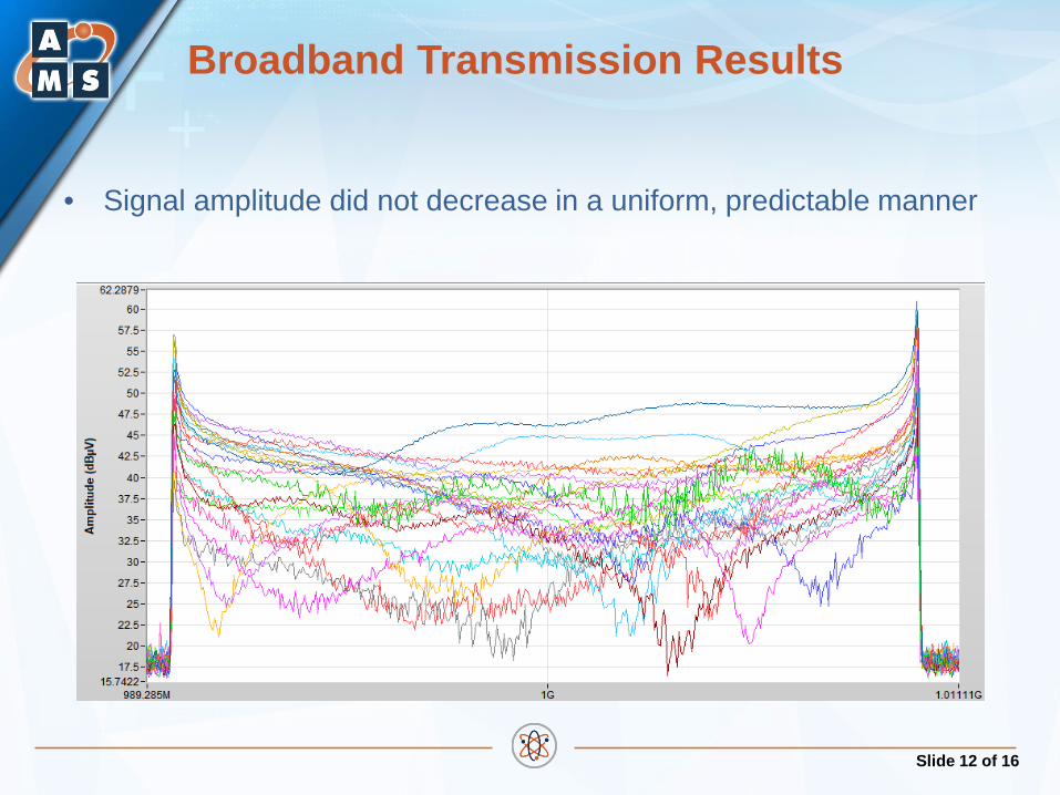
Broadband Transmission Results
• Signal amplitude did not decrease in a uniform, predictable manner

Slide 13 of 16
Interference Caused by Faults in DAS Cables and Connectors
• Examples Faults that cause Passive Intermodulation (PIM)– Loose metal flakes– Rough / irregular metal edges– Poorly made components – Poorly installed connectors– Bad terminations– Under/Over Torqued connections
Poor Connector Installation Practices

Slide 14 of 16
Detecting DAS Faults
• Can be identified using traditionally impedance measurements – Poorly installed connectors– Bad terminations– Under/Over Torqued connections
• New methods are being researched to identified the following using non-invasive measurement techniques
– Loose metal flakes– Rough / irregular metal edges– Poorly made components

Slide 15 of 16
High Level Research Goals
• Nuclear Industry Goals: – Establish reliable wireless connectivity within nuclear power plants– Enable wireless monitoring of many, currently unmonitored plant systems– Find wireless sensors suitable for NPP environments
• Research Goals: – Address implementation concerns with the use of DAS technology– Develop system hardware and measurement techniques for identifying
aging/degradation of DAS components– Provide commercial wireless technology integration services to nuclear power
plants and other industries
Wi-Fi
LTE
Spectra Link
WirelessHART
Other
Wi-Fi
LTE
Spectra Link
WirelessHART
Other
WRLSS206-01
Radiating “Leaky” Cable

Questions?
Thank You!