distributed by: national technical information service...
TRANSCRIPT

......... .....
AD-776 389
RIFLE-GAS LAUNCHED GRENADE CONCEPT
Robert E. Duncan
Rock Island ArsenalRock Island, Illinois
September 1973
DISTRIBUTED BY:
National Technical Information ServiceU. S. DEPARTMENT OF COMMERCE5285 Port Royal Road, Springfield Va. 22151
*-O4 - -
SECURITrY CLASSIVICATIOM OF THIS PAGE OrIfft DOBa £,itOeed
RV CMt DOCUMENTATION PAGE BEFREOMLETNG _OR
1. IMPORT NU-MmEr 2 3 0%fT ACCESSION MO . 3 - R FCIPIENT *S CATAL "um naER
y: : SZ 2 ~ ~Grenade Concept _ _ _ _ _ _ _
RifberGa La uncheanna
9. PRFORINGORGAIZAION AME ND DDRES S. PERFOGRAMINELERO.TRPOROET TASBE
Small Arms Weapon Systems Directorate AREA S WORK UNIT NUMUER
GEN Thomas J. Rodmau Laboratory 1W562604A621:-0lRlock Island, Illinois 61201 1 i____________
11. CONT14OLLING OFIýICIE NAME AND mADDma. 12 REOTDT
Small Arms Weapon Systems Directorate September 1973GON Thomas J. Rodman Laboratory!3NUBROPAERock Island, Illinois 61201 61
14L MONITORING AGENCY NAME c ORESS(U differethoest o CommuollindOffics) IS. SECURITY CLASS. (of this ISO"M)
Unclassif iedIS ECLASSIFICATION/DOWNGRADING
16. 1JISTRIUIITION STATEMENT (of 11d. Report)
Approved for public release; distribution unlimitedU
17. DISTRIBUTION STATEMENT (tit the abatract enllterd In Block 0.It diffeenta horn RhP011)
it SUPPLEMENTARY NOTES
It. KEY WORDS (Co~laotome. anrwoside it necessay and l&'wttlly by block mmbrn o)
Firearms, guns, grenade launchers, cartridges, projectiles, grenades, pro-[pellants, small arms asminition, gun mechanisms, gun camp nents, weapon firingmechanisms, gun launchers
20 JABSTRACT (Coetihmu On tvme. Old* It necosear and Ids"ItfI by block "Unubot)
the reeoot describes a feasibility study on a novel approach for launching a40cmm grenade. The study was undertaken with the goal of conceiving anddeveloping a future grenade launcher which would be applicable to the FutureRifle System Program. This program'advocates a weaporn system which is a/ combination of both a rifle (point Lire) and a grenade launcher (area fire).To maximize integration of the launcher to the rifle design, it was theorizedto utilize rifle propellant gases to launch a grenade projectile. Thej
DD I1JAMN7-0 147 EDITION oF I NOV 6S13I OBSOLETE<
SECURITY CLASSIFICATION OF THIS PAGE (When Data Entreed)

StCUNTY CLASSIFICATION OF THIS PAGI4 D0a Xhemfl
20. Abstract Continued:
proposed concept would provide for reduced grenade ammunition costs, raducednumber of launcher component parts, lighter total weapon system weight, andmore grenade rounds per combat load. A concept which contained all of theabove features was ganerated, designed, fabricated, and Zested. The reportdescribes the various facets •i..hch went into each stage of its development.Feasibility of the proposed concept was demonstrated by the final achievementof muzzle velocities comparable to standard 40me grenade lat..-chers.
SECURITY CLASSIFICATION OF THIS PAGE(UWer Date Znatd)
ABSTRACT
The report describes a feasibility study on a novel approach for
launching a 40mm grenade. The study was undertaken with the goal of
conceiving and developing a future grenade launcher which would be
applicable to the Future Rifle System Program. This program advocates
a weapon system which is a combination of both a rifle (point fire) and
a grenade launcher (area fire). To maximize integration of the launcher
L to the rifle design, it was theorized to utilize rifle propellant gasesfto launch a grenade projectile. The proposed concept would provide for
reduced grenade ammunition costs, reduced number of launcher component
parts, 11-hter total weapon system -eight, and more grenade rounds per
combat load. A concept which contained all of the above features was
generated, designed, fabricated, and tested. The report describes
the various facets which went into each stage of its develcpment.
Feasibility of the proposed concept was demonstrated by the final
achievement of muzzle velocities comparable to standard 40mm grenade
* launchers.
3 3<
I

• • • • • L. " ... .. • - - ,-_ - -...- -• •
/3
FOREWORD
Mr George L. Reynolds, GEN Thomas J. Rodman Laboratory ond Dr Kenneth
Richards, Lockheed Electronics Co., formerly of the GEN Thomas J. Rodman
Laboratory should be given special credit for their significant contribution
to this study. Mr Reynolds was responsible for the design of the fixture,
while Dr Richards performed the mathematical analysis of the concept.
/U
Si&
A
V _-
TABLE OF CONTENTSPage
Abstract ------------------------------------------------------ i
Foreword -............ ii
List of Figures ------------------------------------------- iv
Introduction----------------------------------------------
Result ------------------------------------------------------ 3
Conclusions -------------------------------------------------- 11
Discussion
A. The Concept ------------------------------------------ 12
F B. The Analysis ------------------------------------------ i5
C. The Design ------------------------------------------- 20
D. The Test --------------------------------------------- 22
Appendixes
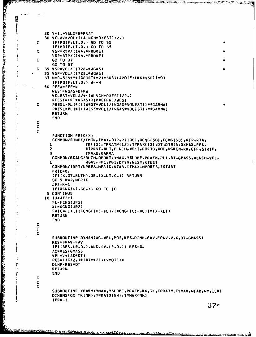
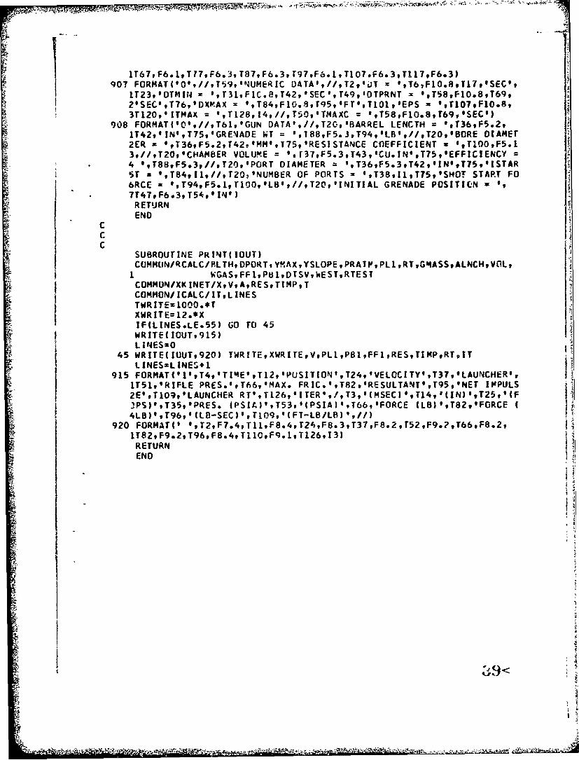
A. Computer Program Printout ----------------------------- A-1
B. Test Program Request ---------------------------------- B-I
I C. Test Results --------------------------------------- C-
I D. Test Records ------------------------------------------ D1
SE. Engraving Force Curves ------------------------------ E-
F. Drawings --------------------------------------------- F1
Distribution -------------------------------------------------- 26
iii 5<
LAIST OF FIGURES
Page
Figure 1: Cross Sectional View of Gas-LaunchedFiring Fixture ----------------------------- 4
Figure 2: Close-Up View of Test Fixture Mounted onModified M16 Rifle -------------------------- 5
Figure 3: Left Hand View of Test Fixture -------------- 6
Figure 4: Top View of Test Fixture ------------------- 7
Figure 5: 40mm Inert Test Grenade Projectiles -------- 9
Figure 6: Multi-Shot Gas Launcher Concept ------------- 13
Figure 7: Schematic Representation of Math Model 16
Table I: Input Characteristics for Math Model -------- 17
Figure 8: Pressure/Time Curves for Rifle Barreland Launcher Chamber ------------------------ 25
Figure 9: force,'Distance Curve for Barrel Engraving
and Friction Forces; .2in/min --------------- E-2
Figure 10: Force Distance Curve fcr Barrel Engravingand Friction Forces; 2in/min -------------- E-3
iv
.........

INTRODUCTION
Early in 1970, a program was undertaken with the goal of conceiving
and developing future grenade launchers. Drawing upon some of the
rationale endorsed by the Future Rifle System Program, one approach
considered was a weapon system which contained two weapon elements; a
rifie and a grenade launcher. It was observed that one way to obtain
maximum integration of area fire and point fire into one weapon would be
to use as many of the existing rifle parts in the design and operation
of the launcher as possible. it was then theorized that if we could
employ the same principles used in the gas system for automatic weapons to
launch a grenade (i.e., tapping off gas pressures) then we could achieve
a high degree of integration and also at the same time eliminate the need
for a grenade cartridge case. This would provide for reduced ammunition
cost, reduced number of launcher component parts, lighter weapon system
weight, and more grenade rounds available per combat load.
In mid 1970, a concept was generated which contained all of the
features described above. The area fire component was comprised
basically of a barrel preloaded with t.o or more grenade projectiles.
The source of energy for launching the projectile was obtained by
tapping off a portion of the propellant gases of the point fire weapon
component. To fire a grenade, a conventional rifle cartridge had to
be fired. The launcher was conceived as a multi-shot, semi-automatic
device, lightweight and compact with speedy operation, and of simple
f construction. A selector switch was included in the weapon design
S7<

which provided f-r a -Ace between area fire and point fire.
In about a.-* 1971, new impetus was given the effort and the concept
was revived and examined in-depth. A preliminary mz.~heaatical analysis
wz, made to determine the feasibility and also predi:z the desirability
of fabricating a test fixturp. The analysis proved favorable and a 40M,
sing'.,-! sht test f" cture was designed and fabricated. With the fabrica-
Ain if tb- ce.t fixture, testing was commenced to determine the
ce.asi6ii'; .: -he concept. The achievement of comparable muzzle
velociti ..;tween the gas launched concept and a standard 40mm system
was established as the criteria Lor feasibility. It was concluded
that since the same standard projectile was used in both weapons,
coI!3javable muzzle velccities would also give comparable exterior and
terminal performance characteristics.
2
Out IA

RESULTS
Based on a farorable preliminary mathematical analysis of launching
a grenade solely by rifle propellant gases, work was initiated in-
house on the design of a firing fixture for determination of feasibility.
j With the objective of the effort being the demonstration of feasibility,
i 40mm was selected principally due to availability of comparative data
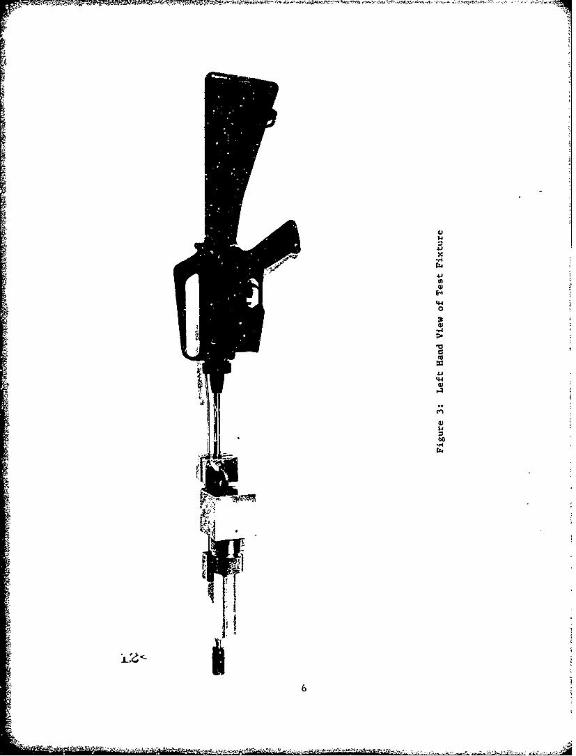
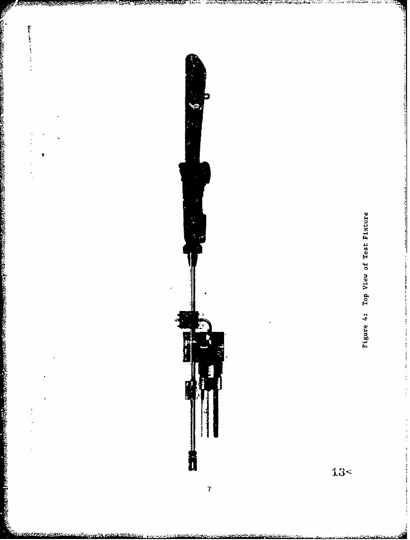
from the M79, 40mm, Grenade Launcher. The design of the firing fixture
can be noted in Figure 1. The M16Al Rifle was selected as the point
fire element of the weapon system concept. Photographs of the fabricated
test fixture can be noted in Figures 2, 3, and 4.
From August 1971 to Mrrch 1972, the 40mm gas launched grenade concept
went through successive cycles of test, evaluation, modification, and
retest. This effort culminated with the achievement of muzzle velocities
comparable to those produced by a M79, Grenade Launcher. This achievement
met the feasibility criteria set for the concept. Additionally, the
testing also examined other features whose interaction played a role ii.
the resulting muzzle velocities. These features were the effects of
engraving forces, obturation, gas port size and location, and initial
chamber free volume. The muzzle velocities of the rifle, its
corresponding operation, and the resulting recoil forces wer! also
monitored during the testing.
In the last series of rounds fired, the fixture produced an
average muzzle velocity of 222 fps. This compared favorably with an
average nuzzle velocity of a M79 fired at the same tide of 231 fps.
39<

cc:i
j4J
x44
00.9.4
Z41
cci4- a
I-)
cil

1 144'4
1 41
4 446 0
C4
t to
Cj
E43
gx
Z44
m0v4)
4J
Ell
4.4
O
it3
.r4
1.
34
'44
l43
6$
$40
;14
"44

As the grenade velocity increased, due to design improvements, it was
noted that effects of projectile engraving on muzzle velocity decreased.
This was observed through the use of standird and pre-engraved projectiles.
At maximum velocities attained, there was only a 0.67. increase attributable
to using pre-engraved projectiles rather than ones that were not pre-engraved
(See Figure 5). Obturation effects were not monitored for the entire test
but at the lower operating pressures and veiocities, special attempts to
completely seal the bore did produce apprcximately 10% inerease in
muzzle velocity.
The math model used in the initial analysis stage indicated that
a gas port size of .091 inches diameter located 12.70 inches from
the rifle muzzle would produce acceptable results. However, during
testing, it was found that this combination did not rrovide sufficient
gas flow and pressure. The rext development stage mrved the gas port
2 inches closer to the rifle chamber. Sufficient grenade muzzle
velocity was still not obtained. Final modificaticn was to triple the
cross-sectional area of the launcher gas tube. The result was a gas
tube diameter change from .091 inches to .166 inches. This final configura-
tion did produce the high uazz.le velocities noted previously. Within the
limits of the test, little effect on grenade muzzle velocity could be
attributed to the magnitude of initial free volume of the launcher chamber.
The test plan noted in Appendix B describes the procedure used to
determine this result.
When designing the firing f-.Lture to mount on the M.16 barrel, special
)L4<
1s

na. CD)> tr.
< -4
Ai
W 0 $0
a: a:
0~, ~ V
0..4
'2-1
attention was made not to modify the M16 gas tube. One of the objectives
of the test was to determine if launching the grenades as proposed would
adversely affect the operation of the rifle. One malfunction that was
persistant during the entire test was failures to eject the spent M16
Rifle cartridge. High speed motion pictures (3500 frames/second) showed
that the case was extracted but insufficient travel prevented ejection.
It was a general trend that as the muzzle velocity of the grenade
increased, the muzzle velocity of the M16 bullet decreased. This
ranged from 3200 fps down to 2900 fps. These particular values can be
noted in Appendix C; Test Results. Recoil forces of the rifle/launcher
test fixture were also measured. However, due to the test set-up, this
was more a qualitative comparison rather than a quantitative determination.
Generally speaking, the firing of the grenade as proposed in this report
increased the loads seen at the shoulder by a factor of 2 te 2 1/2
of those of a conventional MI6Al Rifle. This is attriburtLle to the
double impulse firing of both the rifle cartridge and launching the
massivc gren-ade.
The noise levels for the system was also recorded. There was no
appreciable difference between the fixture firing and a standard
M16 Rifle.
Finally, blank ammunition was fired in the modified 1416 with a XMl5
blank firing attachment to determine the feasibility of launching the
grenade. The results gave minimal velocities (less than 100 fps). These
can be noted on Page C-4.
10

CONCLUSIONS
An overall conclusion drawn from the study is that the theory of
launching a 40mm grenade projectile solely by the use of surplts
rifle propellant gases is valid. This was demonstrated by the
attainment of muzzle velocities comparable to a standard conventional
grenade system.
At this point in the study, ic appears that the concept discussed
in this paper offers a method of improving the cost/effectiveness of
the standird system. This could be achieved through a reduced cost
of a cartridge by eliminating the need for a grenade cartridge case.
Furthermore, with the elimination of the cartridge case, a reduced
bulk would be realized and thus more rounds could be carried per
combat load.
Even with these significant features to be gained, there is still
one major question that has to be addressed before full acceptance of
the concept ib possible. It is the question of the simultaneous launch
of two projectileb - a rifle projectile and grenade. The problem lies
in the trajectory angle. In order to reach maximum grenade range,
the rifle/launcher %eapon system has to be elevated to approximately
40 degrees. Unfortunately, this also gives maximum range for the rifle
projectile which has about 6-7 times the range of the grenade. In effect,
the rifle projectile goes long past the intended target into an unknown
or unintended region.
"17<

DISCUSSION
A. The Concept:
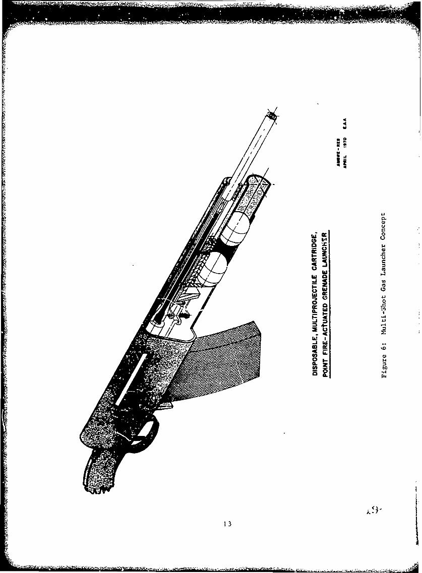
The study discussed in this report emanated from a concept generated
at ihe US Army Weapons Command in mid 1970. The proposed idea advocated
close integration with and utilization of the rifle trechanism for the
design of the grenade launcher. Figure 6 shows the concept concerned.
The mode of operation is as follows:
1. A selector switch on the ridle stock is used to select either
the area fire (grenade) or point fire (rifle) mode of operation.
2. When the area fire mode is selected, a valve system is turned,
via linkages, so that the grenade gas port is uncovered.
3. A magazine preloaded with two nr more grenade projectiles;
has been attached to the grenade receiver. The initial barrel position
allows for alignment , the gas ports.
4. To fire the gc~nade, the rifle trigger is pulled and a standard
ball rifle cartridge is fired. As the rifle prujectile passes the grenade
ggan port, the expandii-g gases flow into the launcher chamber behind the
forward grenade proj%,:tiles. Thir provides for launch of t*-e projectile.
5. The grenade fi.ring impulse causes the barrel to shear a retaining
lip and allows the barrel to set back to its rearmost position. This
movement closes off t.ne forward gas port and uncovers the rear one. The
second round could tien be immediately fired by pulling the rifle trigger
again and firing another rifle cartridge.
12
X 4
a: 0
w 04.aa
j C,
1i 0
I/ W
.ja.w
131

6. When the point fire mode is selected, the rotating valve closes
off both grenade gas portb Therefore, when the rifle is fired, only a
rifle projectile exists the bore.
To support the concept, a mathematical analysis was undertaken in
mid 1971 for determining the theoretical feasibility of the approach.
This approach is discussed in the next section.
414
-l1

'P. ihe -Mathematical Analysis:
SThe detailed mathematical analysis undertaken to determine feasibility
of the approach consisted basically of an interior ballistic program.
TIe analysis was performed on a simplified design rather than the multi-
ahot concept originally conceived. Figure 7 is a schematic representation
Sthe math model. The analysis considered in-bore time, grenade position,
Srade muzzle velocity, launcher bore pressure, rifle bore pressure,
gienade frictional forces, resultant grenade forces, and net grenade
o:i:zz*- impulse. The program also examined grenade barrel length, grenade
,ore di.ameter, chamber volume, gas port diameter, number of gas ports,
;renade weight, and gas efficiences. A list of some of these parameters
:aa be noted in Table 1. A printout of the program can be noted in
A ppendix A.
Based on the iUL t characteristics, the feasibility of ea Ii set of
i,-,1ditions was determined primarily by the resulting muzzle velocity.
*;Ifse coordination was maintained between the design engineer and theI
- :aPl'Yst so that exercise of the math model would produce design parameters.
The above list of characteristics include not only input values
z-t also outputs. The determination ot Lhe values for the inputs in
,-tine cases were obtained from experience plus existing systems. However,
z,( some cases special studies had to be run. The value for the grenade
j:n-bore time was obtained from a pressure-time curve for the 40mm round.
I The grenade position was one of the values calculated in the program
.%s was the grenade rmzzle velocity. The launcher bore pressure was a
I- (t-tinued on page 18)S!15

W6
iii'44Ion 00
414
0 ý
MdI. us~O .MA iaw 0
0, VC j -'w w'
96-M z Q l
4 0 MdI Wd wd
mm u .
Ii. 4 z
U.4
16

TABLE 1
INPUT CHARACTERISTICS FOR MATH MODEL
Input information for gas launched grenade firing fixture
I-1. Length of Rifling: 5.85 in.
2. Port and tube diameter - .091; Port and tube length - 4.13
3. Initial volume:
I a. Tube .0256 in3 (tube diameter .091, length 3.96)
b. Projectile skirt: .129 in 3
34c. Total of a and b: .156 in 3
d. Initial volume for various linear components of volume (includes
3c above)
(1) 0 in. -. 156 in 3
i3(2) .16 in. - .188 in 3
(3) .125 in - .410 in 3
3(4) .250 in. - .664 in
(5) .375 in. - .919 in 3
(6) .500 in - 1.173 in
(7) .625 in - 1.427 in 3
4. Length of free bore. (Initiation of rifling is used as referel.ce
point. Positive sign indicates engraving).
a. - .130 in.
b. - .062 in.
C. .000 in.
d. + .062 in.
e. + .130 in.
17
4 ' %-I= - -=,-- <= ~'-

calculated figure based on in-put rifle gas pressure, gas efficiency, and
volume considerations. Values for the rifle bore pressure were obtained
from M16 P-t data obtained from Frankford Arsenal. The P-t curves were for
a series of positions down the bore of the rifle which gave a collective set
of data for each rifle shot. A P-t curve was selected whose position nearly
proximated the location of the grenade rifle port. These data can be found
in Frankford Arsenal Report Number R-2066, "Study of the Pressure
Distribution Behind the M193 Projectile When Fired in the M16 Rifle
Barrel" dated January 1973. The net grenade muzzle impulse along with
the resultant grenade forces were calculated figures. One major
factor effecting these values was the in-bore frictional forces. In
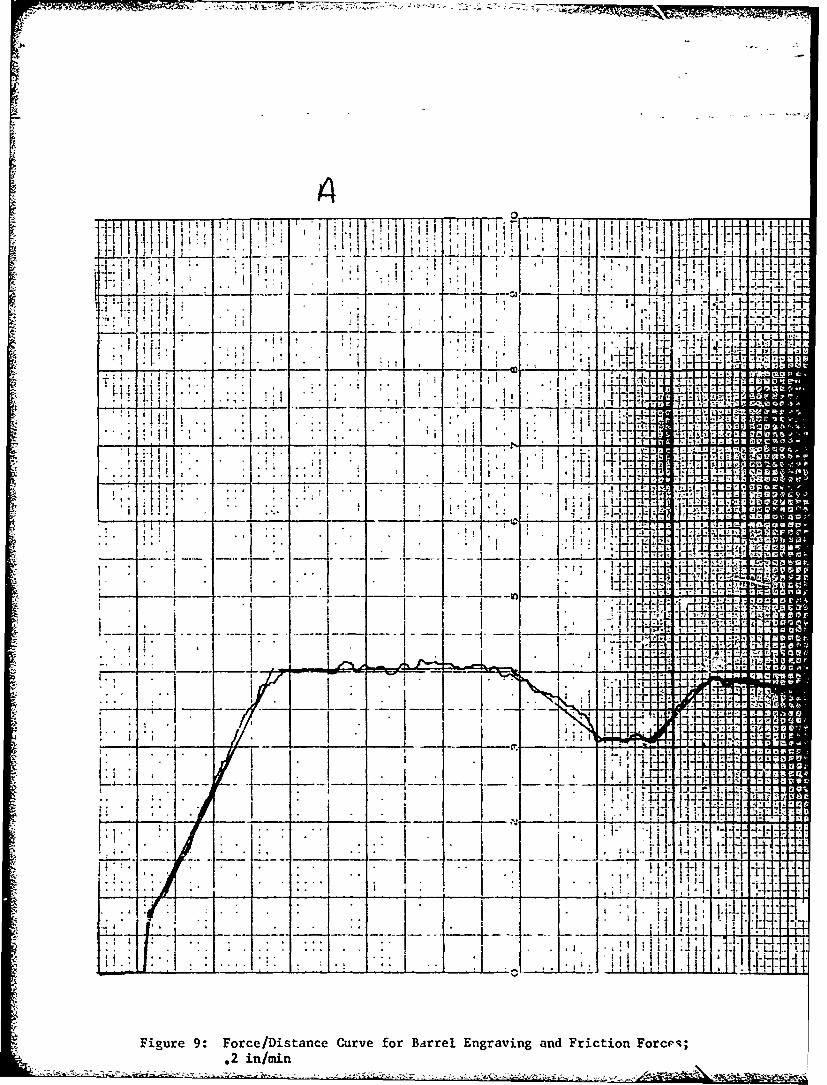
order to determine these, a special study had to be run. A force-
distance curve was generated for the projectiles as they were pushed
through a 40mm barrel. Two typical curves for the engraving and
frictional forces can be noted in Appendix E. In Figure 9, the two
high initial peaks represent engraving of the two rotating bands.
The cross head on the Instron Test Machine was run at speeds of .2
iv rain. In Figure 10, the cross head was run at 20 in/min. The high
speed was used to simulate high rates of loading experienced by the
grenade when fired. Even though the test machine speed was quite low
compared to the actual conditions; it did give some insight into the
effects of loading as a function of speed. Generally speaking, as the
loading increased, the peak values decreased. This ranged from 950 lbs
down to 600 lbs for loading rates of .2 in/min up to 20 in/min respectively.
24 18
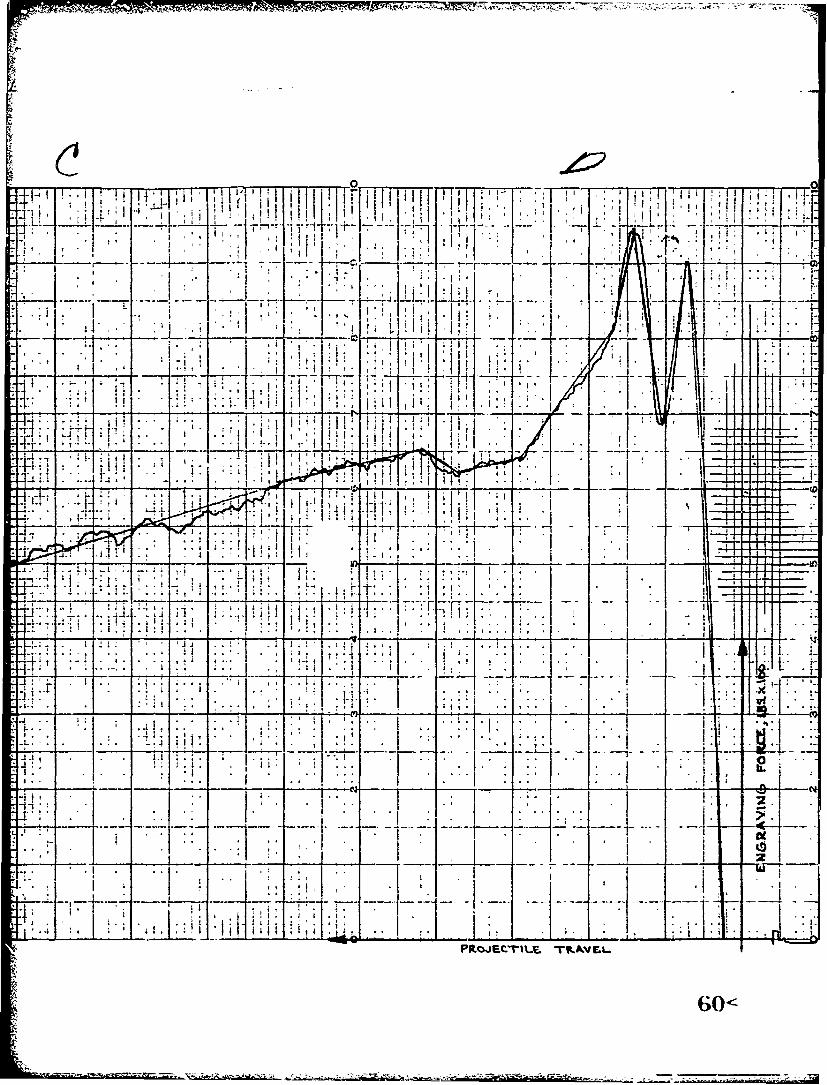
Additionally, as the rates increased, the initial peaks smoothed out.
This can be seen by comparing Figures 9 and 10. In Figure 10, the second
major peak probably arises from a constriction in bore of *ne form or
another. In addition to indicating the force/distance curve for engraving
forces, it also could serve as a histogram of the bore diameter and conidition
over its entire length. The very last peak is at the muzzle end of the
barrel indicating projectile ejection. The resulting curves were approximated
by best-fit straight-line-segments for use in the computer program. A
by-product of the engraving test was the production of pre-engraved XH387
projectiles for use in subsequent testing of the firing fixture.
One of the listed pararuetric inputs is the number of gas port: used.
This pertained to grenade ports and the option to vary the number was
put in the program due to the uncertainty that was associated with tLe
volume of gas that might be needed to successful;.y operate the mechanism.
As it turned out, only one gaa port was required. The last significant
feature to be discussed on the input values was the value for gas efficiency.
A math model for automatic weapon gas t.ystem was modified and tailored to
the needs of the grenade system. The basic model is recorded in WECOM
Technical Report No. RE Th-71-80, dated June 1971, author - Mr Curtis
D. Johnson. The purpose of the gas model was to determine tlhe gas flow
and pressures seen at the base of the grenade projectile after the gas
passed through thr grenade gas tube. In basic terms, the grenade's actionz
are quite similar to that of a gas piston in a conventional gas system and
was treated accordingly.
19

C. The Design:
The assembled firing fixture can be noted in US Army Weapons
Command Drawing No. 71D21503; Appendix F. The drawing shows only
"the launcher assembled to a modified 1416 barrel. For purposes of
testing, this assembly was then in turn assembled to a standard
M16 Rifle receiver. The launcher was positioned on the M16 Rifle
so that the launcher did not interfer with the original shape of
the M16 gas tube. This dictated that the 1416 be layed on its side;
so to speak. However, it was positioned such that the ejection
port was facing upward when the launcher was in the firing position.
This facilitated filming of the 116 ejection port. It should be
noted that there is only one moving Lirt on the launcher and that
is the barrel.
In drawing number 71D21508, a standi.rd 116 Rifle barrel was
modified as shown. Also depicted are several changes that were
made to the barrel as testing proceeded. The first was to move
the .093 + .001 eiameter grenade gas port 2 inches closer to the
rifle chamber. The other major change was to machine a .166 + .001
long by .093 wide slot in the existing grenade gas port. Both
modifications were performed to increase the grenade gas pressure.
The 40mm grenade barrel is shon in drawing number 71D21509. It
was modified from an existing aluminum 40mm barrel. But due to a
lack of original material on the grenade barrel, a steel sleeve
(no. 71D21512) was required to provide a sufficient threaling
20

surface. The outside of the sleeve had punch marks on it to assist
in adjusting the initial volume of the launcher. This was performed
by merely screwing the sleeve either in or out depending upon a
predetermined volume requirement. This was determined by knowing the
pitch of the thread and the area of the chamber. Loading the launcher
was performed by fully unscrewing the barrel and inserting a grenade
projectile (Figure 5), Minimum initial free volume was achieved by
turning the loaded barrel in until the projectile base contacted the
breech insert; No. 71D21505. The insert was contoured to fit the
projectile's base to assist in obtaining minimum free volume. The
insert also had provislons for accepting "0" ring seals. The seals
were used in the initial testing to determine the effects of obturation.
However, during a major bulk of the testing, the outer ring was
removed but the inner one retained. No detrimental effects could
be observed for this condition.
Part No. 71D21510 was used to seal off unused gas ports.
During the course of the testing, sometimes it was desired that
either the M16 or grenade port be sealed off. This is when the
part was used.
21 -7<Sni

D. ThMTjest:
In conjunction with basic testing of the concept for determination
of feasibility, several other side line activities developed. One
such effort was that dealing with the effects due to engraving. As
the test records will show, three basic projectile configurations
were considered; no rotating bands, pre-engraved, and standard
unengraved projectile. They were tested in the listed order so
as to work up to the worst-case condition. This precaution was
taken even in light of the irntial analysis which indicated the
system was safe. At the lower pressures and velocities, there
was a marked difference in performance between the pre-engraved
and st3ndard. But, as the pressures and velocities approached
levels which were consi.'tent with other standard grenade systems,
the difference between the two types of projectiles decreesed to
a low value. In fact, to reduce the frictional and engraving
forces to a minimum, fired projectiles were caught in a barrel
of rags just beyond the velocity coils and were then in turn
used over again.
"! secondary study undertaken during the course of the .esting
was obturation of the projectile. There were eight basic configurations;
standard and pre-engraved projectiles, with an "0" ring, with grease,
and with a plastic dip. The "0" ring was obtained from the hlgh
velocity 40mm grenade projectile which is used for waterproofing.
The greased rounds used a silicone, high temperature grease which
22
4.

I was rubbed around and in the rotating band3. The plastic coated
rounds were dipped repeatedly in a liquid urethane to buili up a
coating. This was done to reduce the cleprance between the rotating
bands and the rifling grooves. The test results in Appendix C show that
of the various methods of sealing, the urethane dipped projectiles
performed the worst. The performance between the grease and the "0"
ring were comparable. Additionally, the two just mentioned obturation
methods gave improved results over the standard condition. However,
the last few rounds that demonstrated feasibility were shot without
the aid of obturation devices. It was one otjective of the test to
prove feasibility without the aid of other costly features or devices.
To back up the instrumentation, the testing was also filmed
at 3500 frames per second. The qualitative nature of the obturation
effects were correspondingly recorded. Additionally, a 40mm, M79
Grenade Launcher was filmed in a like manner. The lack of obturation
on it was quite surprising. This was evidenced by the quantity of
propellant gases blown by and preceding the projectile.
One of the requirements of the test 'as to record the muzzle
velocity of both the rifle and grenade or each shot. To do this,
special instrumentation used for recording machine gun velocities
was required. This allowed for recording the imizzle velocities
of both projectiles for each shot. Two sets of velocity screens
were used with this equipment. Firing records for initial portion
23
%7
of the test can be noted in Appendix D.
Selecting round number 149 from Appendix C as a sample round,
pressure/time curves can be seen in Figure 8. The top curve is
for the gas pressure measured in the M16 barrel directly over the
grenade chamber pressure. The calibration of the top is 10,000
psi/cm on the vertical scale and 0.5 m1i" ieconds/cm on the
horizontal. The grid pattern are n-e cm squares. The lower
curve calibration is 500 psi/cm on the vertical and 0.5 milliseconds/cm
on the horizontal. The peak values are approximately 18,000 psi
for the rifle bore pressure and 1900 psi for the grenade. These
pressures produced a rifle muzzle velocity of 2928 fps and a
grenade velocity of 225 fps. A standard projectile was used with
0.188 in" free volume. The previously described slotted gas port
was used in conjunction with a .166 diameter grenade gas tube.
J30< 24
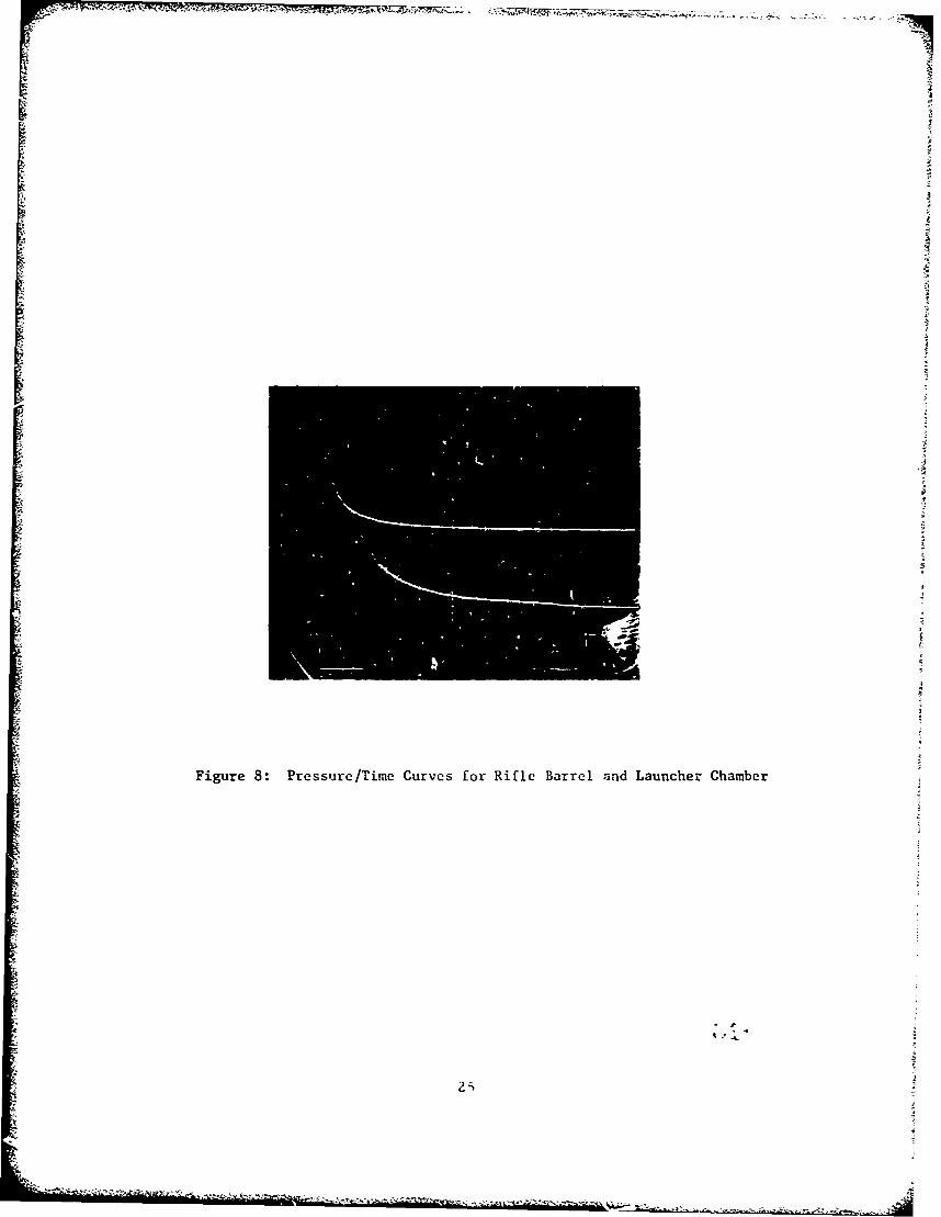
Figure 8: Pressure/Time Curves for Rifle Barrel and Launcher Chamber

A NI
APPENDIX A
S J
C
c * FEASIBILITY STUDY OF GRENADE LAUNCHER CONCEPT FOR R, DUNCAN *
* COMMON/RINPT/TMINTMAXDTPP1100),XCNG(50),FCNG(50).RT1',RTA,I TK(12),rPRATM912,tTYMAX(12),DTDTMIN,DXM4A~,EPS,2 DTPRNTBLIDLNCHVDLIPORTDXOIWGRENRKEýFFtSTRTF,3 TMAXCqGAMMACOI4MON/RCALC/BLTH,PDORTYMAXYSLOPEPRATMPLIRTGMASSALNCHVOL,I WGASvFFIPB1,D1SVtWESTvRTESTCOMMON/XKIrJET/X~vAvRES9TIMP9TCOMM0N/INPTINPRESNFRICNTABITNAXNPORTStISTARTCOMMON/ ICALC/ITtL INESEXTERNAL PRESBPRESLiFRICIOUT=6Gm32*2PI-3. 141593
1000 READ15,90CEND=1O) ICNTRL
GO TO(1,293,4t5,6),ICNTRL
c READ PRESSURE DATA
C 1 R.AD(5,9O1) NPRESTMINTMAXDTP
READ(59902) (FiJ),J=1,NPRES)DO 11 J=19NPRESP1..) P(J ).14.7
11 CONTINUEGO TO 1000
CC READ FRICTION DATAC
2 READ(5,900) NFRICREAD(59902) IXCNG(J)tJzINFRIC)READ(59902) (FCNGUj),J=19NFRIC)DO 21 JzlNFRICXCNG(J)=XCNG(J)/12.
21 CONTINUEC GOTO 1000
C READ GAS DATAC
3 READ(59901) NTABRTP,RTAgGAMMAREAD(5,903) (TK(J),TPRATMIJ),TYMAX(J),J=1,NTAB)GO TO 1000
CC READ NUMERIC DATAC
4 READC5,901) ITMAXDTDTMINDXMAXEPSDTPRNTTMAXCDXMAX-DXMAX/ 12,.OTSVEzDTGO TO 1000
CC READ GUN DATA 3&c<
5 READ(5,902) 8L1,DLNCHVOLIPORTDXO1,WGRENRKEFFREAD(59900; NPORTS, 1START

t3LTHzBL 1/12.
r XO&XOI/12.
C CALCULATE DIAMETER OF EQUIVALENT SINGLE PORTC
OPORT=PORTO*SQRT(FLOAT(NPORTS))IFIISTART*EQ.0) GO TO 51.READ(59902) STRTFGO TO 1000
51 STRTF=FRIC(XO)GO TO 1000
6 DTzDTSVECALL YPARM(YMAX,YSLOPE,PRATM,RKTK,TPRATMtTYMAX.NTAB,12,IER)CALL HEACIIOUT)11NES=56IT:..
4 A -0.
XXXOP11= 14 .7T IMPO0.RES=O*RT=RTAGMASS=WGREN/GT=TMINALNCH=(PI/4. )*( (DLNCH/25.4i**2)VOL-VOLTIWGAS=VOLr*(o,075,1728.)FFI=STRTFPBI:PRESO(TMIN)CALL PRINT(IOUT)IFCFFI*NE*0.) CALL START(IOUTtPRESBtPRESL)OT=DTSVECALL SHOOT(IOUT,PRESBPRESLFRIC)GO TO 1000
900 FORMAT(2IS)901 FORMAT(I10,7F10.0)902 FORMAT(8F10.O)913 FORMAT(15F5*0)10 STOP
ENDCCC
SUBROUTINE START I OUT,PRESBPRESL)COMMON/RINPT/IMIN, TMAXDTPP( 100) XCNG( 50) ,FCNGI 50) ,RTPRTA,1 TK(12),TPRATM(12hoTYMAX(12),DTDTMINDXMAXEPS,2 DTPRNTBLIOLNCHVOLIPORT0,XOI,WGRENRKEFFSTRTF,3 TMAXC#GAMMACOMMON/RCALC/BLTH,DPORT,YI4AXYSLOPEPRATMPL1 ,RTGMASSALNCH,VOL,
1 WGASFF1,PB1. SVvWESTRTESTCOMMON/XKINET/XtVARES* %rtTCOI4MON/ICALC/ITL INESPLMIN: (FF1/ALNCH)414.7
TLPRNT=T5 IT*IT.1T T T+ OTII PB2=PRESBITT 3PBAVz (PB1+PB2)/2.
34<z PL2uPRESL(0.,PBAV*PL1)

IF(PDIF.GT.0.) GO TO 20h10 WGAS=WEST
TsTTPB IsPB?FL 1=PL2RT=RTESTIF((UIT-TLPkNT)/DTPRNT).LE.0.99).AND.(POIF.LT.0.)) GO TO 15CALL PRINT(IOUT)TLPRNT=T
15 IF(POIF.EQooo) RETURN.F(T.GE.TMAX) GO TO 30ITxOGO TO 5
20 IF(UPDIF/PLMIN)oGT.EPS) GO TO 25POIFzO.GO TO 10
25 OTzDTI2,GO TO 5
30 WRITEfIOUr,930) X,T4. RETURN
930 FORMAT(bO%,//,5XPI***** PROJECTIL!ý STUCK IN 8ORE AT X It*F10,79I. *I FT9 T ',lF1O.7,' SEC **)
ENDCCC
SUBROUTINE SHOOT(IOUT,PRESB,PRESLFRIC)COMMON/RJNPT/TM14JTMAX,DTP,P(ICO),XC.NG(50),FCNG(501,RTPRTA91 TKU.ý2),TPRATM(12),TYMAX(12),DTDTMINDXMAXEPS,
t2 DTPRNTBLIDLNCHtVOLIPORTDXOIWGRENRKEFFtSTRTF,3 TMAXCiGAMMACOMMON/RCALC/IBLTHOPORTYMAXYSLOPEPRATJ~,PLI,RTGMASSALNCNVOLt
1 WGAS FF1, PB 1,DT SV, WESTtRTE STCOMMON/XKINET/XVAvRESTIMP, TCOMMON/INPT/NPRESNFRICNTAiBITMAX,NPORTS,ISTARTCOMMON/ICALC/IT,L!NESTLPRNT=TOTCK=2.*CTMINFFI=FRICIX)
10IT=0OXEST=V*0T4(A/2. )*DT**2
11 IT=IT+lIF((DXMAXGE.OXEST).OR.(DT.LT.DTCK)) GO TO 20DT=DT/2.
V OXEST=OXEST/2.20 TEST=T.DT
XEST=X.DXESTPB2=PRESB (TEST)POAV= (PB1.PB2)/2.FF2zFRIC(XEST)FAV=(FFI4FF2)/2.PL2=PRESL (DXESTPBAV#PL1)FPAV=ALNCH*( 0.5*tPLI+PLZ)-14. 7)CALL OYNAM(ACKVCK, XCKRES,OJMPFAV,FPAVVX,DTGMASS)OXCKzXCK-XIF((0.005*ABS(DXEST-DXCK)).GE.(EPS*DT)) GO TO 50T=TEsrV=VCKAXACKX=XCK

PB 1=P 2FFI1%FF2PLI=PL2VOLzVOLI+(ALNCH*(X-XOI))TIMP=TIMP+DIMPW GAS =W ES TRT=RTESTIF(U((T-TLPRNT)/DTPRNT).LT.O.99).AND.(X.LT.BLTHI) GO TO 10CALL PRINT(IOUT)TLPRNT=TIF(X.GE.BLTH~) RETURNIF(V.LT.0*) GO TO 70IF(T.GE.TMAXC) GO TO 80GO TO 10
50 IF(IT.GE.IT#4AX) GO TO 60DX ES T= X CKGO TO 11
60 WRITE(IOUT9925) XT,1T70 WRITE(IOUT,930) X,T
RETURN80 WRITEIIOUT,935)
RETURN925 FORMATV1','////t5X*'FAILURE TO CONVERGE AT X = 'FI0.791 FT* f
1,FIO.79' SEC IN '914,' ITERATIUNS*****EXECUTION TERMINATED')930 FORMAT('O',II,5X,@***** PROJECTILE STUCK IN BORE AT X - PIFlO.7i
I ' FT, T = lFl0.7,' SEC *****')935 FORMAT('00',I,5X,****** MAXIMUM CALCULATION TIME EXCEEDED *S'
ENDCCC
FUNCTION PRESBIT)COMMON/RINPT/TMINTMAXDTP,P(1CO),XCNG(5C),F',NG(50),RTPRTA,I TK(12),TPRATM(12),TYMAX(12),DT,DTI4IN,DXMAXtEPS,2 DTPRNTBL!,DLNCHVOL1,PORTDXOIWGRENRKEFF,STRTF,3 TMAXC,GAMMACOMMON/INPT/NPRES,NFRIC,NTAB,ITMAXNPORTSsISTARTPRESB=14 .7IFI IT.GT~fJ4AX).0 .(T.LT.TMIN)) RETURNjT2=INT( {7-TMINl/DTP ).IIU=sr2+1PL=Pl JT23PRESB=PL+t(P(II~f-4rL~fDTP)*(T-TMIN-(OTP*FLOAT(JT2-1fl))RETURNEND
CCC
FUNCTION PRESL(DXEST,PBORE,0LI)COMMON/RINPT/T~lNTMAX,OTPP(10O),XCNG(50),FCNG(5O),RTP,P.TA,I TK(12),TPRATM(12),TYMAX(l2hvDTOTMINDXMAX,EPS,2 OTPRNT,BLI,OLNCtI,VOLI,PORTDXOI,WGREN,RK,EFFSTRTF,3 TMAXCGAMMACOMMON/RCALC/BLTHDPORTYMAXYSLOPEPRATMPLIRT,GMASSALNCt4,VOL,1 WGAS)FF1,PB1,OTS'V,WESTiRTESTPO IF= PBOP.E-PL IAPDIF=ABStPO IF)PRAT=APDIF/AMAXI (PBOREgPLI)IF(PRAT.LT.PRATM) GO TO 20YmYMAXGO TO 30
20 Y-1.4.YSLOPE*PRAT30 VOLAVxVOL ( (ALNCH*DXEST /26)
C IF(PDIF.LT.0.) GO TO 35VS(PDIR*TP(4.*PBORTO 35
C VSP=RTP/ (144.*PBORE)VSGO TO 37 *PBRE
C GO TO 37G5 TSsOL/3728*GS
C 35 VSP=VOL/ (1728.*WGAS)37 W0.525*Y*(DPORT*WGA)*SR(PI/R*S))37FWPDIF.LT.(CO.) W=-w(ADI/(KVS))50 FFW=EF*WTO)W-50ST=WGAS+FFWVOEST=VOLAV+( AF C*XET3/.RTLEST= (T*UAS+RTPNC*EFF)/EST)/.
C REST=PLI*(UETVL/WGAS+vOLEST))FGAMMA)C PRESL=PLI*(((WEST*VOL3/(WGAS*VOLEST))**GAMMA)
PRETURN ((ES*JL/W.A*OET)*GMARETUNDEN
CC
FUCIN RCXFUCTION/FRINP/MI4XDPP10)XN(5)FN(0)RPRCOMO/RNTK(12),TPRA~tTP,(IC),TAXCN(52),DTDTNG(O,DKMAXp,2 DTK(2)RNA1(1TBLDLCHOLIPOTDDTXMIGRNRKA~EPST9F3 DTPRMAXCGAKMAP(R~tDWR~o~EFtTRFCOMN/CLCBTHDPOtYMAKSOEPAMP1RIASANHVLCOMMWGASFFBLTH ,POR81A,DSVWETPRATEST 9T#MStLNHVLCIMONINT/PRS,NFR[CN1TABITIAXNRTSSTARFRCzOMMNIP/PEFI.TA#TAvPRSITFRIC(0.GTBT)O.XL. )RTR00(.TBT).R(o~~) 5RETURNRI00 5 =K- NRI
IF(XCNGIK).GE.Xi GO TO 105 CONTINUE
10 IU=JF2+1FL=FCNG(JF2)XL=XCNG(JF2)FRIC=r.L+UIFCNGIIIfl-FL)/XCNG(I)-XL))*(X-XL))RETURNEND
CCC
SUBROUTINE DYNAM(AC,VEL,POS,RES,DIMPFAVFPAVVX,DTGMASS)j RES=FPAV-FAVr IF((RES.LE.0.).ANDo(V.IE*O.fl RES=O.ACxRES/GMASSVEL-VG(AC*DT)P0S=(AC/2.)*(nT**2)+(V*DT)+XDIMP=RES*OTRETURNEND
C
CI C SUBROUTINE YPARMYMAX,YSLfPE,PRATMRK,TKTPRATMTYMAX,NTAB,NP,IER)DIMENSION TK(N14),TPRATM(NM),TYMAX(NM)IER~-1

IF(URK.GE.TKUW.)AND.(RK.LE*rK(NTAB))) GO TO 5WRITE(69900) RK
900 FORMAT(0'9,T59,'RK = lTI0,.F6..2tT18,1; THIS VALUE IS OUTSIDE YHE RAINGE OF THE TABLE')RETURN
5 UO 10 K=29NTABKU P=KIF(TK(K).GE.RK) GO TO 15
10 CONTINUE15 KL=KUP-1
TKL=TK(KL)POR=(RK-TKL)/(TK(KUP)-TKLIPL=TPRATM(KUP-1)PRATI4=PL+(POR*(TPRATM(KUP)-PLI)YL=TYMAX (KI)YMAX=YL+(POR*(TYMA~li(KUP)-YL))YSLOPE= (YIMAX-1. )/PRATMIER=ORETURNEND
CCC
SUBROUT INE HEAD( lOUT)COMMON/RINPT/TMIN, TMAXDTPP( iCO) ,XCNG(50) ,FCNG(50) ,RrPRrAiI TK(12),TPRATM(12).TYMAX(I2),DT,0TMINiDXMAXEPS,2 DTPR1NT,BLI,OLNCi1,VOLIPORTDXOItWCAqENRKEFFSTRTF,3 TMAXCvGAMMA
7 COMMON/RCALC/BLTH,DPORT,YMAX9,YSLOPEPRATIP,PL1,RT,GMASSALNCHVOL91 WGAStFF1,PBliDTSV,WESTRTESTCOMMON/INPT/NPRESNFRICNTAi, ITMAXNPORTSISTARTWRITEC IOU?, 900)WRITE(IOUT,901) NPRESTM IN, TMAX1,DTPWRITE(IOUT,902) (P(J),pJ=1,NPRES)WRITE(IOUT,903) NFRICWRITEC IIUT,904) ()XCNG(J)tFCNG(J),J=19NFRIC)WRITE(IOUT9905) RTPRTAYMAX,YSLOPEPRATM,NTABWRITE( IOUT,906) (TK(J),TPRATM(J)tTYMAX(J)tJ=1,NTAB)WRITE( IOUT,907) DTDTMIN,DTPRNTDXMAXEPSITMAX,TMAXCWRITE(IOUT,908) BLliWGREN,DLlCHRKVOLI,EFFPORTDISTART,NPORTS,I STRTF,XOI
900 FRA( '/,3,'***********************1********************',/,T32,'*',T98,'*',/,T32,'* FEASIBILITY STU2DY OF GRENADE LAUNlCHER CONCEPT FOR R. DUNCAN *',/,T32,'*'#T98#'*
901 FORMAT('O',T60,'PRESSURE DATA'i,//,T1O,'NPR1-: = ',T18*139T30#'TMIN1= s,T37qFlO.B,T48,'SEC',T60,'TMAX = ',T679FI0.8,T78,'SEC',T90,'DTP2 = ',T96,F1O.8,T107,'SEC'#//,T52,'RIFLE BORE PRESSURE (PSIA)fv/)
902 FORI4AT('O',5X,8Fl5.1)903 FORMAT('0',//tT54, 'FRICTION DATA',i/,T55,'NFRIC = '*T63)12,//,119v
1'FT',T28,'LB'7rT39,'Fr',T48,'LB',T59,'FT',T68,'LB',r79,'FT',TB88,LB2' ,199 ' FT', TiOB, 'LB' ,/;
904 FORMIAT('0', r15,F7.4,T25,F7.2,T35,F7.4,T45,F7.2,T55,F7.4,T65,F7.2,IT75, FT.4,T85, F7.2,195,F 1.4, T105,F7.2)
905 FORMAT('Ol*//vT57v'GAS DATA*,//*T15,'RTP =*,T219F8.lpT35,'RTA1,T41,F7.IT54,'YMAX = ',T61,F5*3,T72,'YSLOPE = ',T8lF6.3,T92,'PRA2T14 = '9TlOO,F5-3#,/,T60,0NTABi = ',T67,13,//,19t'TK',T17,'TPRATM',3T27,'TYMiAX',T39,'TK' ,T47r'TPRATM',T579'TYMAX',T69, 'TK',T77,'TPRATM4',T87,'TYMAX',T99, 'TK' ,T1)7, 'TPRATM',TI17,'TYMAX',//)
906 FORMAT('0',T7tF6., rIT7,F6.3, T27,F6.3,T37,F6. 1,T47,F6.3,T57,F6.3,
38<k
IT67,F6.1,T?7,F6.3,T87,F6.3,F97,F6.lTl07,F6.3,Tll7,F6.3)907 FORMAT('099//9T59t'NUMERIC DATA$,//,T2,'.aT z 1vT61FIO,8#flI7#*SEC't
MT30DTMINJ = ',r3lFlC.8,T42t'SEC',T49,'DTPRNT = 1#T58,FlO.8*T69v2@SE=CT76,IDXMwAX = 1tT84tFI0.8vT95,'Fr',T1I,'pEPS = ,r1I07,FIO.8,3TI2090ITMAX = 1,T128tl4t//,T50,tTMAXC = 1,T58tFIo.8,r69,'SEC1)
908 FORMAT('10'*//,T61,'GUN DATA',//,T20,'BARREL LENCTH = %rT36,FS.2,1T42,'IN',T759*GRE'IADE WT = ',188,F5.3,T94,*LR',//,T20,'BORE DIAMEr2ER x %tT36,F5.2,T42t'MM',T75,ORESISTANCE COEFFICIENT x *,T100,F5*139//,T20,'CHAMBER VOLUM~E = *,r37,F5.3tT439'Cu.IN',T75,'EFFICIENCV4 #,T88,F5.3,//,T20t6PORT DIAMETER = 1tT361F5*3tT42,91NvT75t11STARST z ',T849I1,//9T20-3NUMBER OF PORTS = ItT38,1,T75OSHO! START FO6RCE a %tT94,F5.1,Y100,'LBt//,T2Q,'INITIAL GRENADE POSITIE-N lo7T4TtF6o3,T54#$IN*)RETURNEND
CCC
SUBROUTINE PRINT(IOUT)COMMLIN/RCALC/ PLTN, DPORT, YMAX Y SLOPE, PRAT~t'PL11,RT ,G'ASS, ALNCH, VOLt1 WGAS,FF19Pl31,DTSViNEST,RTESTCOMMON/XK INET/XV,AtRESTIMP,T ý
COMMON/ICALC/1TLINESTWRITE=1000**TXWRITE=12.*X Dro4
WRITE(IOtJT,915)L I 4ES=O
45WRITE(IOIUT#920) TWRITtXWRITEVPLI,PBI,FFlRESTII4PRTITL INES=L INEJ+ 1
95FORMAT('1*,T4,'TIME',T12,WPUSITION',T24, 'VELOCITY'tT3?7,LAUNCHERV2'T510RIFLAUNCES.96,MX FRIC.',T82,'RESULTA.NT*,T95t'NET IMPIJIS
2E'T10#'LUNCERRT*,TI26,*ITER09/,T3,#(MSECIoTI4,'(IN)I,T25t*(F..PS)'9T35,'PRES. (PSIA)',T53,'(PSIAJ,*T66t1FORCE (LB)o#T82,'FGRCE4L8)',T96t'(La-SEC)*,rIO9,'IFT-LB/L8)',//)L
920 FORMATI' 'tT2,F7.4,TIIF8.4,124,F8.3,T37,FB.*2,r52,F9.?,r66,F8.2,lT82,F9.2tT96,F8.4,T11CF9. 1,TI26,13)
RETURNI-
EN
......

APPBENDIX B
4 . - 0
IIg
I -i40
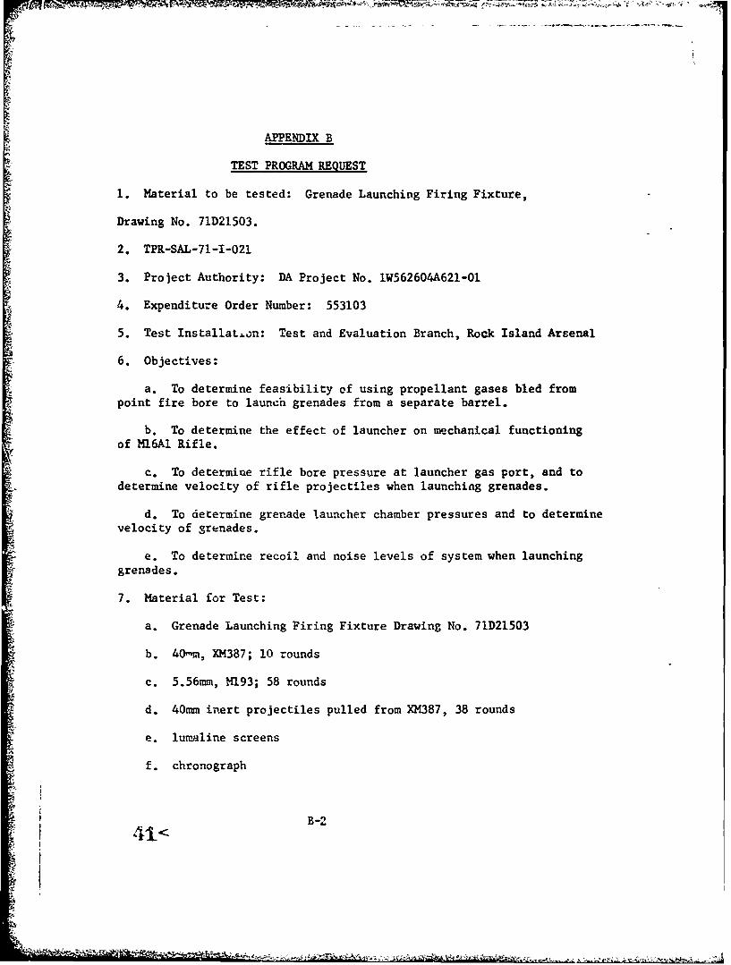
APPENDIX B
TEST PROGRAM REQUEST
1. Material to be tested: Grenade Launching Firing Fixture,
Drawing No. 7lD21503.
2. TPR-SAL-71-1-021
3. Project Authority: DA Project No. 1W562604A621-01
4. Expenditure Order Number: 553103
5. Test InstallaLtn: Test and Evaluation Branch, Rock Island Arsenal
6. Objectives:
a. To determine feasibility of using propellant gases bled frompoint fire bore to launch grenades from a separate barrel.
b. To determine the effect of launcher on mechanical functioning
of Ml6Al Rifle.
c. To determine rifle bore pressure at launcher gas port, and todetermine velocity of rifle projectiles when launching grenades.
d. To determine grenade launcher chamber pressures and to determinevelocity of grenades.
e. To determine recoil and noise levels of system when launchinggrenades.
7. Material for Test:
a. Grenade Launching Firing Fixture Drawing No. 71D21503
b. 40mn, XM387; 10 rounds
c. 5.56mm, M193; 58 rounds
d. 40mm inert projectiles pulled from XM387, 38 rounds
e. lumaline screens
f. chronograph
4B-2
j I41
-!

g. photogranhic equipment
h. pressure measuring equipment
i. depth micrometer 3-4 inch
J. decibel level recording equipment
k. recoil level recording equipment
1. one 1479 Grenade Launcher; one Ml6A1 Rifle; one MK6Al Riflewith M203 Grenade Launcher.
8. Description of Test:
a. Test set-up 8.(2)(a), (b) and (c) will be photographed andsubsequent set-ups as designated by the test engineer. This will includestill photographs plus high speed movies. High speed movies will be madeon -renade firing only.
b. Velocity records will be made oi each projectile fired exceptwhere noted.
c. Pressure-time curves will be recorded for all firings except
where noted.
d. All firings will be performed in semi-automatic mode.
e. Firing schedule: (To be performed in the sequence noted below)
(1) Launcher Comparison Subtest:
* (a) Use one M79 Grenade Launcher, one M16AI Rifle with1M203 Grenade Launcher, and one M16AI Rifle.
(b) Fire five rounds of XM387, 40nin ammunition through
both the M79 and the M16/M203. Fire five rounds of H193, 5.56mmammunition through the M16Al Rifle.
(c) Measure the recoil force at the butt plates, noise,and muzzle velocity of each round.
(2) Initial Check Test:
(a) Rifle gas port closed. Grenade gas port closed.
B-3

1. Grenade launcher removed from rifle. Rifle boresighted.
2. Fire five rounds. Measure pressure at grenadegas port on all five rounds. Measure noise and velocity of first andsecond rounds only. Retain target.
(b) Rifle gas tube connected to rifle. Grenade Launcherremovel from rifle.
1. Grenade launcher gas port closed. Rifle boresighted.
2. Fire five rounds. Measure pressure on launcher gasport on all five rounds. Measure noise recoil and velocity on first andsecond rounds only. Retain target. Observe functioning of rifle mechanism.
(c) Rifle gas tube connected to rifle. Grenade launcherattached to rifle.
•. Grenade launcher port open. Rifle bore signted.
2. Fire five rounds of M193 ammunition. Measurepressure at launcher gas port on all five rounds. Measure noise, xecoil,and velocity on first and second rounds only. Retain target. Observefunction of rifle mechanism.
(3) Soft Catch Projectile Subtest:
NOTE: Rifle Gas Tube and Grenade Launcher Assembled toM16 Rifle.
1a) Loa.. odified 4Omm projectile with front of projectileflush with t, zle of grenade launcher barrel. Fire one round. Measurepressures at iauncher gas port end chamber. Also measure noise, recoil,and muzzle velocities of both the grenade and 5.56m= bullet.
(b) Load modified 40m projectile with base of projectileseated agai..st receiver insert. Fire one round. Measure pressure atlauncher port and chamber. Also measure noise, recoil, and muzzlevelocities of both the grenade and the 5.56mm bullet.
(4) Launcher Variable Volume Subtest:
(a) Gas Tube and launcher attached to Y116.
1. Load grenaae launcher barrel drawing no. 71D21509
43<B-4
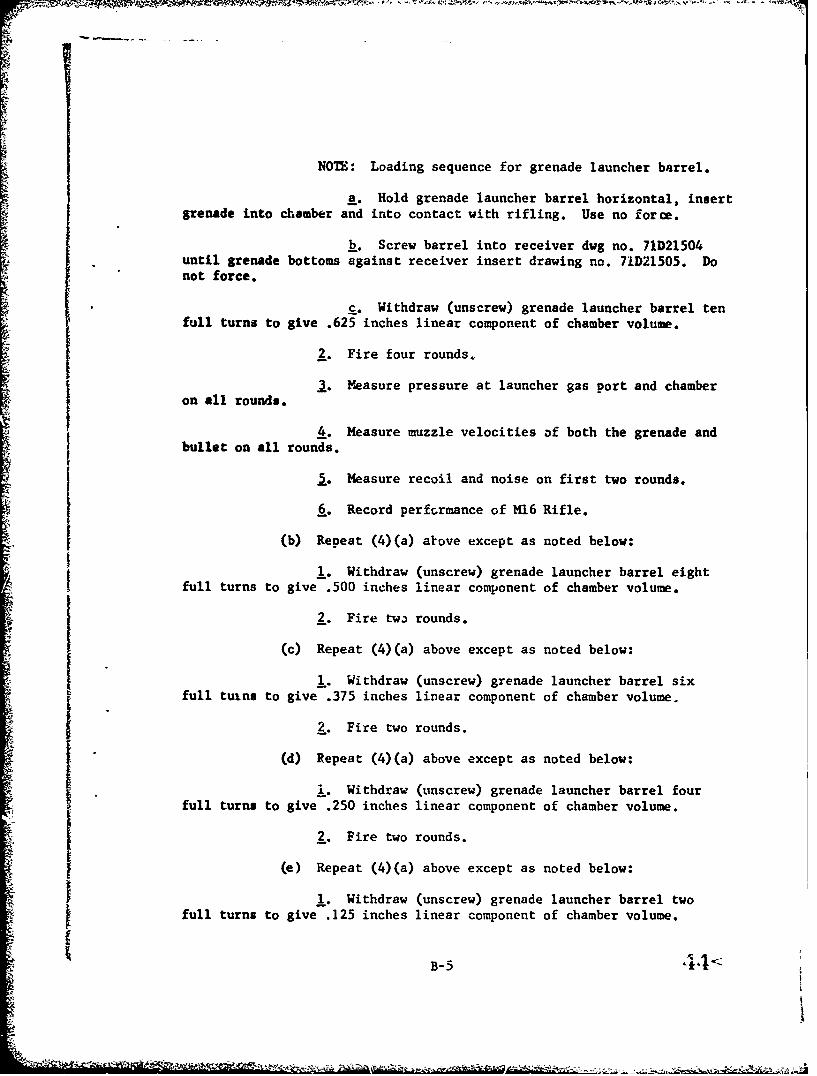
NOTE: Loading sequence for grenade launcher barrel.
A. Hold grenade launcher barrel horizontal, insertgrenade into chamber and into contact with rifling. Use no force.
b. Screw barrel into receiver dwg no. 71D21504until grenade bottoms against receiver insert drawing no. 71D21505. Donot force.
S. Withdraw (unscrew) grenade launcher barrel tenfull turns to give .625 inches linear component of chamber volume.
2. Fire four rounds.
M. easure pressure at launcher gas port and chamberon all rounds. I. Measure muzzle velocities of both the grenade andbullet on all rounds.
I. Measure recoil and noise on first two rounds.
6,. Record perfcrmance of M16 Rifle.
(b) Repeat (4)(a) akove except as noted below:
1. Withdraw (unscrew) grenade launcher barrel eightfull turns to give .500 inches linear component of chamber volume.
2. Fire two rounds.
(c) Repeat (4)(a) above except as noted below:
1,. Withdraw (unscrew) grenade launcher barrel sixfull tuins to give .375 inches linear component of chamber volume.
2. Fire two rounds.
(d) Repeat (4)(a) above except as noted below:1 '. Withdraw (unscrew) grenade launcher barrel four
full turns to give .250 inches linear component of chamber volume.
2. Fire two rounds.
(e) Repeat (4)(a) above except as noted below:
1. Withdraw (unscrew) grenade launcher barrel twofull turns to give .125 inches linear component of chamber volume.
S44<B-5 i
•8I

2. Fire two rounds.
(f) Repeat (4)(a) above except as noted below:
1. Withdraw (unscrew) barrel 1/4 turn to give .025inches linear component of chamber volume.
2. Fire two rounds.
(g) Repeat the one test of (4)(a) thru (4)(f) whichreailted in the highest grenade velocity, except in this test the riflegas port is closed. Fire two rounds.
(5) Free Bore Subtest:
Load grenade into chamber and hold in contact with rifling.Do not use force. Measure distance from front of projectile to face ofmuzzle insert. Screw barrel into receiver until grenade contactsreceiver insert. Do not use force. Set chamber volume to that selectedin (4)(g) above.
(a) Withdraw (unscrew) the barrel two additional turns.Using the muzzle insert dwg no. 71C21588 and kepth micrometer, pushgrenade rearward .13 inches. Fire tw,' rounds.
(b) Withdraw (unscrew) the barrel one additional turn.Using muzzle insert and depth micrometer, push grenade rearware .06inch. Fire two rounds.
(c) Load grenade into chamber and hold in contact withrifling. Do not use force. Do not give grenade free bore. Fire tworounds.
(6) Variable Pre-Engraving Subtest:
Load grenade launchet barrel and screw 'ztto receiver vintilgrenade contacts receiver insert.
(a) Screw barrel in one additional turn to achieveapproximately .06 inch pre-engraving. Use hand pressure only. Setchamber volume to that selected in (4)(g) above. Fire two rounds.
(b) Screw barrel in two additional turns to achieveapproximately .13 inches pre-engraving. Use hand pressure only. Setchamber volume to that selected in (4)(g) above. Fire two rounds.
(7) Final Configuration Subcest:
45< B-6

Select configuration which resulted in highest velocityto this point. Fire four additional rounds.
(a) Record noise and recoil levels.
(b) Measure muzzle velocities of grenade and 5.56mm bullet.
(c) Measure pressure at launcher port and chamber
(d) Record two shots on high speed movies (FASTEX)
(8) Effect of Obturation Subtest:
Use same configuration as in (7).
(a) On dwg 71D21503 remove O-ring, MS 28775-60 and ring,backer MS29774-127, Fire four additional rounds.
J. Measure velocities of grenade and 5.56mm bullet.
*o Measure pressure at launcher port and chamber.
a. Record two shots on high speed movies (rASTEX)
(b) On drawing 71D21503 remove all O-rings and backer rings.Fire four additional rounds.
1. Measure velocities of grenade and 5.56mm bullets.
2. Measure pressure at launcher port and chamber.
3. Record two shots on high speed movies (FASTEX)
9. Perform any uther task determined necessary to achieve objective.Mr R. Duncan and.or Mr. G. Reynolds will be present at all testing.
10. Coordination: Testing will be coordinated with Mr R. Duncan, ext.4661. The final report, test records, and films will be forwarded tous, SWERR-S-I.
B-7

- ~ ~ ~ ~ ~ ~ An l c-~ - - ~ - ' - - - --
47<
c-1

APPENDIX C
TEST RESULTS FROM THE GAS LAUNCHED GRENADE CONCEPT
PROJECTILES GRENADE MUZZLERD FIRED BARREL VELOCITY.fpsNO. 5.56mm 40mm GRENADE PROJECTILE CONDITION POSITION 40,,- 5.56mm
1 M93 --- N/A N/A -- 31972 " --- to -" 31733 " "" -t 31994 " " " -- 32175 t -" 319i6 f" " - 31967 , " -" 32158 " " " -- 31909 " " -- 318910 " " " -- 321611 "- " -" 321912 " " -- 318513 " XM387 No rotating bands Seated Flush NR NR14 " " " " NR 317615 " " " " NR 308416 " " " " NR 313517 " " Pre-engraved " NR 316218 " " " " NR 318619 " " Standard " NR 314620 o" Pre-engraved " NR 317121 XM387 " " NR 315122 " N1. N/A -- 314923 " i-- -- NR24 " " " -- NR25 it-- AR26 o" " - NR27 " -- NR28 K1.93 N/A N/A -- NR29 " XM387 Pre-engraved Seated Flush NR NR30 " " 103 316731 of I of 104 NR32 " " " 101 322833 " " " Backed Out 1 Turn 112 321534 i s " Backed Out 2 Turns 105 321035 " " Standard Backed Out 1 Turn 45 318936 t" " 53 320737 " " " " 54 322338 it ti 67 321039 o f " 67 3244Grenade gas port moved 2" closer to rifle chamber "40 " --- N/A N/A -- 313441 " --- it -- 316242 " -- 318743 " XM387 Standard Backed Out 1 Turn 110 Il
48< C-2* I-
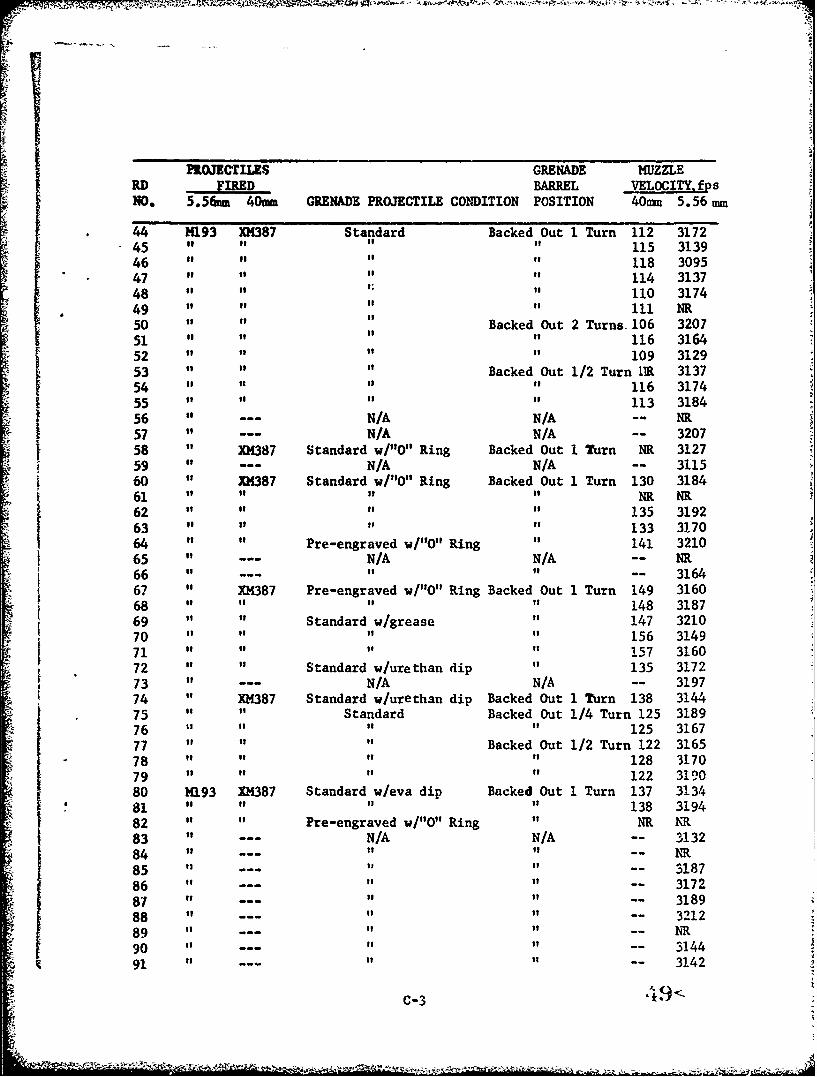
PROJECTILES GRENADE MUZZLERD FIRED BARREL VELOCITY, fpsNO. 5.5&im 40umm GRENADE PROJECTILE CONDITION POSITION 40rmm 5.56 mm
44 H193 XH387 Standard Backed Out 1 Turn 112 317245 " t t t 115 313946 118 309547 114 313748 110 317449 " "" 111 NR50 Backed Out 2 Turns. 106 320751 116 316452 109 312953 Backed Out 1/2 Turn 1RE 313754 116 317455 113 318456 --- N/A N/A -- NR57 --- N/A N/A -- 320758 XM387 Standard w/"O" Ring Backed Out I Turn NR 312759 N/A N/A -- 311560 XH387 Standard w/"O" Ring Backed Out 1 Turn 130 318461 H " of NR NR62 135 319263 133 317064 Pre-engraved w/"O" Ring 141 321065 N/A N/A -- NR66 --- -- 316467 XM387 Pre-engraved w/"O" Ring Backed Out 1 Turn 149 316068 148 318769 Standard w/grease 147 321070 156 314971 " 157 316072 Standard w/urethan dip 135 3172
73 --- N/A N/A -- 319774 XM387 Standard w/urethan dip Backed Out I Turn 138 314475 Standard Backed Out 1/4 Turn 125 3189
76 " 125 316777 t " " Backed Out 1/2 Turn 122 3165
"78 " 128 317079 s o 122 319080 M193 XM387 Standard w/eva dip Backed Out 1 Turn 137 313481 " to " 138 3194
82 " Pre-engraved w/"O" Ring HR NR83 N/A N/A -- 313284 "i If --
85 "" -- 318786 " " -- 317287 "" -- 318988 --- " -- 321289 R-- h90 -- -- 314491 ---- 3142
C-3

PROJECTILES GRENADE MUZZLERD FIRED BARREL VELOCITY. fpsNO. 5.56-m 40mm GRENADE PROJECTILE CONDITION POSITION 40nm 5.56mm
92 14193 - "- N/A N/A 316493 " XH387 Pre-engraved w/grease Backed Out 1 Turn 170 NE94 " " t 168 HR95 o Pre-engraved w/"O" Ring 169 NR96 " It 156 NR97 i Standard w/urethan dip 155 NR98 t it 154 NR99 Pre-engraved w/urethan dip Ni ru100 " " Pre-engraved Backed Out 1/4 Turn NR 3021101 " 1 " of NR NR102 " " to 211 NR103 " " " NR 3099104 " NR 3010105 211 2983106 210 2969
107 " " 211 3001108 206 3014109 " " Standard " Ni 3077
o10 It " 198 3065ill it " 202 2985
112 " " " 206 3023113 " " Pre-engraved Backed Out 1/8 Turn 208 3053114 " It 204 3079
115 t Backed Out 1/16 Turn 203 3096116 " " " Backed Out 3/8 Turn 204 3101117 " " " NR 3070118 " " " Seated Flush 206 3077119 " " Pre-engraved w/eva dip Backed Out 1/4 Turn 208 3132120 Blank " Pre-engraved " 84 --121 " " " 85122 " " " Backed Out 1/8 Turn 85123 " " Backed Out 1/16 Turn 85124 " " Pre-engraved w/eva dip " 103125 to" " " NR126 it" " 65127 " " Standard Backed Out 1/4 Turn NR128 " " Pre-engraved Seated Flush NR --
129 M193 "o Backed Out 1 Turn Ni NR130 " "of NR NR131 to NR NR132 " " " - " NR 3075133 " NR " 4 3055134 " -- N/A N/A -- 3110135 " -- " " -- 3007136 " XM387 Pre-engraved Backed Out 1/4 Turn 218 3074137 " " Pre-engraved v/eva dip Backed Out 1/2 Turn 219 3081
138 " " Pre-engrav'ed Backed Out 3/4 Turn 211 3021139 " " " Backed Out 1/4 Turn NR NR140 " " Standard Backed Out 1 Turn 209 3016
50< c-4
,ae
"PROJECTILE GRENADE MUZZLERD FWD... BARREL VELOCITY. fpsNO. 5.56mm 40um GRENADE PROJECTILE CONDITION POSITION 40Lma 5.56mm
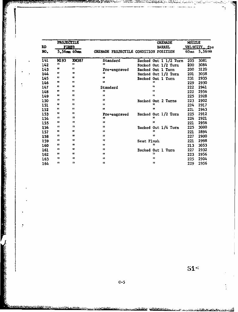
141 1193 XH387 Standard Backed Out 1 1/2 Turn 205 3081142 " is B3cked Out 1/2 Turn 200 3084143 " o Pre-engraved Backed Out 1 Turn 200 3120144 to to Backed Out 1/2 Turn 201 3058145 " it Backed Out 1 Turn 231 2935146 " " of 229 2930147 " o Standard " 222 2941148 " " of 222 2956149 " o to 225 2928150 " Backed Out 2 Turns 223 2902151 " 224 2917152 " " 221 2943153 " Pre-engraved Backed Out 1/2 Turn 225 2912154 " " is 224 2921155 " of 221 2956156 " " " Backed Out 1/4 Turn 225 3000157 " " " 221 2894158 " I tI 227 2900159 " " Seat Flush 221 2998160 " "It 213 3053161 "i Backed Out 1 Turn 227 2932162 " " 223 2956163 " i t " 225 2904164 " 229 2956
51<
C-5

CPmixi
~5 I
V
4;

-n %a Sý r.. P% CDi~ %D a - a. w
.o r 4. r4. r %.40 i-r *n In 0 1 1 u in
in aa -j %D in ~ wl % 4- -40 r% IP
r % - h 0 Dc D mcz4e -4 4 3ý
cotI 0e en 40 en4 00 m iC - n en.. in cn 40
(.4 4 41 0- 4 4 .
0 o4 13 C- I 1
0 -4.* -4
LU
a4 64
50~4 u~
w4 14 Ua
* 2 0 1:: ci
054 ,f. "ci 54
0i A H V ~I 4
0 : : 1.-0 oi to
00
ci4 co
ci ý *r-j
0V1- -4 m 54"U ci XciU;
-4: en %n -- :n -: %
0 0.

ch ga I
-~ P- -n C -Z 4-
C; W4 0J C'w-n %a c
Mr ~ ~ ~ ~ UNC W no!c
Z4 r, ~C% Cý 4
Cdd Z x
2 3- o
0 x
00
LUU
6 a
-V a
0 0 01
a.L >*V KU' : '-410. -- -r.
go 0- - :COIala
a ow
LL'U
CI a -' 4
LI a

z 1j-. .q ý 4 -4 C4 - 4 W- '- -4 o C, r - i - C-f
4h1 I1 i11 toI% 0 NO m %
u a ""4 4 .4 44 -4*
OIO
0* 0a ON .9 4~~0
00.440 ~ ~~~~ ~~ 4S a S S I S I a S
U - 0
-0 u I
W 049 .
o 0 a 0 00
a0O a inD -
0 4 =0 In J
00
IL U:D. ' 44co4-
O~~~ Oa:0L
Min

r% r
01 tM I cz Z L0 ý r%0 . U.
M6 >
o - .- -o c 4 I ý - 4I I I I0 x in o --T IT ,-. -n L M M e
-4 in N 4 .4 4 .-4 .4 4 .4 P4 s- 4 .- 4 -4 r-4 r4 v- . 4 .4
41W% FU N .44 W N u4 wD 0% 0~ 0~s .'
.4 V -L4 P E40.4X ~X 11$
o0 M 0 c %o .
UU C54151 O 4 ý4 C j 41400S to toU
-< LU 0 0J "4 410 4 1
0S 040z 6 C: 10 :40Q0)vi- 0 : . 9 4 . $4 $4 pD G
$4 54 0.$ 14 $4 145it Atc 0 = 040
0 wo w )C E 4 E 0 Ototo -0 I-S -V4: 14 $4 - 4m : C"" N -4 C 4 4 q am c 05
w- r- -00 14 04 14OtW 4 C .4 >
W GEt V 0 0 V00414
C-' 10"4 ý 0 C-A v i V 0 0 0w I4; Q 4) 4 1 .- 1 4 U U "D W -
ccC V 10 GDc bD a 0 .4a.a04.a4-
3 1 0 -.0 %U . . ~0 %0
0 0 0w V GD V It LM 'U n i14$41 $4 4j 4 . - t 4 ) A 1 L $40U. 0 "4 000 $4 $4g1 41 -4 -4-4
me C)sa) V4 ) 0) V v4 a 0ci4.104 (L w
0 'TIt D0 l.1C-1c 4 L a r co 0% c S4 04 cn ? n
OZ OR-4 44 -. 4.41
V~ 542 to .Vn
-Iall
-- -1 -1
-- 4 4
r-

I LU
z %3 ~ U0 $A 1 Oý 00 I dM .4 4 C14
0
N 4j @1 41 Ec *- ;F3 IL 4 8 4~
lU $4 0 0 C
41 4 1 1F4
lw-41414 : 14C3.4
0 0 0 0 CLod 94 P4P4 0
0 0 U~ Ai 0 -41
4-; 1-3-$4
bow
00
"4 "4 -4 "
0. I u u
P( 4 ý4 ý V
Q 0 4) :> P. >
$4 $4 $4 -

,zLLI
zso
IL,
6 00
zt I-I22
00
LU cui
L Z
I--
0z
%O I!, c~.. ( I
0 0 4cI .UI0~i. 0-i .-D %0 Ln in Cncn
* - .- . 4 - -4 4 ,-4 r4 NI
Sý GO 4 cnl
U,.
0 L
un£%D
!ca~ iz ~ILZ-f

APPENDIX E
-59
! ! 1 ! '* .| --
7.r
4-i-4 r
! I fLI
4
lii .. .... "i.Z "4
4)491. _I.! it li. ..1
'- '4 - -* .4.im •It 4 14 ' - 1 -4
. 7 -
* '
. ._II I .L,
1t *
IL4 I A.-.
I '" I.
]9 14..[++•
i
'4
.2 iin/miI :, . "i : ' . ' °,1 L
Lv'~ *IL .4
.4. ., . . . ,, I t t
Figure 9: Force/Distance Curve for Barrel Engraving and Friction Force's;
•+..+..2 in,/in

H 17H+tit' IT-4 "iH4' :¾, :1 TTTT.+',,+,II I. ;"
;I. I ' .I , - ,H I , *
.. ........ ......
- -- ~~~~ ~I T7
- - - - -+ I I 1
. ..1 . .......:I..
.1..I :" ''- ++'.
-•;i : ,, :+ . . .. *" I"l"
-:- TI- .. ... I* **".''',
1 L L -'it
FoI - ,; !*l .'. .
+I' -- -_----"--
I .i 1'
+i+ " -. -- -
1 .*. -:.: .',:-: -
*_ • ' ' i 'I. ,
IIL+---jHL i• .K7 ... " - '•_.-1. ".. i ll ". . ;
-j ,-:. - --.- . ...- % .'- -"' -- +.,•• ,
�irur�y-rr �4:�-I;H fViP�' T�'1 VFFF�IFF1TTflTTTiITVF
I 1..�7IF I � 'II' � 1 *1 1 �. �
I II :�i
1 4. . . t
I I I
I I44 I j j�t :1'. :1
4 ,�, I �II
- � ii ii ji -�1 I:II
.. I
14 ¶
- - .1 - (LI
-- - I '4* I.�.....i....tI- -r , . 4
-4. **44 I* I
-:(4 i.V.iiltyTy. � I
� 1. �* . 4
* ;:>K* K . I-. Jii>
4 . . . ., 4 .1* - I 41 * I �. I,
. �tT7 IZ� 1* .. jr7'� -]-�-.- -'--I- --
ii I.
I- 1*��TTKj
*I. '4
I I
- I
PR.c�JECT�LL ThAVLL
60<
- - 4 '42 .. - �'- .�

g k .Ty 1%; ýýý,-ý, r .. - ;. _ -,,..
J.1
i r
Xi Ji
If<
FIgure 10 Foc/itneCrefrBre1EgaigadFito ocs
2 in/14-

APPNDI Frwj rr~c~ihb~vj.
Ii
Stt
- ¢ -t.~ t-<~i~-***~-f * <~*---* -- ~,-,

-O1Q 01Ae
u - £~i~O~aL4
11 TI
CD~ IIO
.1 2 sj6i amI <* : ;i

..............fUz la
3t.
ed ps

ili
-FF
IC
CQUa WI~L

Iif
Lnr
trri
I liii LI
ub.
tn
C I U U ±OSIZOILOI 4
a
C
I-
a
I * �I
i
.�?�:a £
�giIIiiii��I14�E�•Kj®
L�1'S
4
a�
+1
2CI
(j7.�. *I
*1�' I
C a I
a U QOSIZUILU 4
*1-
71!0
�
- a
B K -
lit,* a
(4 I a
�'
�0i�iI� I
Ji� I: �w
0
q:j�i ii
C
6*
KS
/
p.
2I-
ii�- I
a I
* I 4
- V. � � -� -. - -

IC U a 6OStZOt�9j 4
C - �1�
- -��1I- -q
ot S
eEl ita
4; - + illI �* t
ll�
I
�I I
jjj;� £ I
ILI
L
I -,
I,
- I
r I
1.. -�- T
* I
* � § Io��. -- ���
-
I
-I-� BI:N
C U * I 4
aZ IL Ij~ L-
cc 0
CACC na

a -I
IN~
0 8r
U ilo
S� 7 - - - -,-� � � '-'.z'Žr�w.- ¾ - - � 4
- � --
i�i
C I a � I 4
r.j
- I.. 3
Ij 3 V
* SII
V '7 -1 '�
'I ,� �
.5 � *' -
'I
-�
ii % I
q I ye)Ii *�1 .- i:j;: £ t
*---T �
'-liiV��7
'� ��Idh I
* I
II -.t.d -�
V a u * I 4
- - - ½�'- 4.

-z¼
I
a I U - aQsI�OuGIItFl-
L.� 0
�
UII *� *1a
I ;1I N
* a(4
I
V-'I -t
a
6�� Pi v
I If �& -� �
IL�:V
I!) �
.1?i�: £ £
a - C
Lii a
'5 / II I
U* §
C
2
.�aJD
a
II
5' 0 U * 4
-�
- - � �