distributed data management in opportunistic …
TRANSCRIPT

DISTRIBUTED DATA MANAGEMENT IN OPPORTUNISTIC NETWORKS
by
CHANCE RAY EARY
Presented to the Faculty of the Graduate School of
The University of Texas at Arlington in Partial Fulfillment
of the Requirements
for the Degree of
DOCTOR OF PHILOSOPHY
THE UNIVERSITY OF TEXAS AT ARLINGTON
August 2016

Copyright c© by Chance Ray Eary 2016
All Rights Reserved

To my father, whose unwavering support, steady counsel, and assortment of
idiosyncracies made me the man I am today.

ACKNOWLEDGEMENTS
My co-chairs, Mohan Kumar and Gergely Zaruba, have been instrumental to my
completing this work in a reasonable amount of time, while facilitating my retention of
a reasonable amount of sanity. Without their patience and guidance, I most certainly
would not have completed my doctorate.
Bahram Khalili was vital in my admission to both the Master’s, and Ph.D.,
programs here at UTA, and has been a tireless advocate on my behalf over the years,
as well as being kind enough to sit on my committee. Many thanks too to both David
Levine, and Yonghe Liu, for their participation in this committee.
The U.S. Department of Education’s Graduate Assistance in Areas of National
Need Fellowship has been a true blessing, which has allowed me to focus on my
research, while maintaining a comfortable standard of living. The staff of UTA’s CSE
Department, especially Pam McBride, exercised a near-infinite amount of patience in
dealing with issues which arose during dispersion of these funds, and they have my
sincere appreciation.
Chiara Boldrini and Andrea Passarella were exceptionally generous for allowing
my use of the HCMM source code, generosity which made portions of this research
much easier.
Michelle has been an understanding and forgiving partner throughout the en-
tirety of my work on my Ph.D., and she has my eternal gratitude. And, of course,
without my father, I never would thrown my hat into the ring at all.
August 8th, 2016
iv

ABSTRACT
DISTRIBUTED DATA MANAGEMENT IN OPPORTUNISTIC NETWORKS
Chance Ray Eary, Ph.D.
The University of Texas at Arlington, 2016
Supervising Professors: Mohan Kumar and Gergely Zaruba
Opportunistic networks (ONs) allow wireless devices, primarily mobile, to in-
teract with one another through a series of opportunistic contacts. While ONs exploit
mobility of devices to route messages and distribute information in the absence of ded-
icated networking infrastructure, the intermittent connections among devices make
many traditional computer collaboration paradigms difficult to realize.
Two such paradigms are distributed transactions and distributed shared mem-
ory (DSM). Distributed transactions are a sequence of operations, executed across
multiple nodes, that must successfully complete as specified by its program, or abort
with no changes to memory. DSM allows multiple, independent nodes to collectively
operate on a pool of memory as if it were a single address space. Originally developed
for traditional networks, both paradigms rely on relatively stable, consistent connec-
tions among participating nodes to function properly. This dissertation facilitates the
employment of distributed transactions and DSM in ONs, by introducing two novel
schemes specifically tailored to work in the presence of erratic inter-device connectiv-
ity, as well as a thorough investigation into optimizing the latter system to produce
the most desirable functionality in a variety of exigent conditions.
v

Distributed Transactions in Opportunistic Networks (DiTON) enables a se-
quence of operations on shared sets of data, hosted across multiple nodes, while
providing global coherency in the event of network interruptions. An implementation
of DiTON, and accompanying experimental results, demonstrate that it is possible
to utilize transactions in ONs. The second scheme discussed is Delay Tolerant Lazy
Release Consistency (DTLRC), a mechanism for implementing distributed shared
memory in opportunistic networks. DTLRC permits mobile devices to remain inde-
pendently productive while separated, and provides a mechanism for nodes to regain
coherence of shared memory if and when they meet again. DTLRC allows applica-
tions to utilize the most coherent data available, even in challenged environments
typical to opportunistic networks. Simulations demonstrate that DTLRC is a viable
system for deploying DSM in ONs. Finally, an analytical model for analyzing the
behavior of memory in DTLRC is presented. The analytical model provides insights
into DTLRC’s performance.
vi

TABLE OF CONTENTS
ACKNOWLEDGEMENTS . . . . . . . . . . . . . . . . . . . . . . . . . . . . iv
ABSTRACT . . . . . . . . . . . . . . . . . . . . . . . . . . . . . . . . . . . . v
LIST OF ILLUSTRATIONS . . . . . . . . . . . . . . . . . . . . . . . . . . . . xi
LIST OF TABLES . . . . . . . . . . . . . . . . . . . . . . . . . . . . . . . . . xiii
Chapter Page
1. INTRODUCTION . . . . . . . . . . . . . . . . . . . . . . . . . . . . . . . 1
1.1 Motivation . . . . . . . . . . . . . . . . . . . . . . . . . . . . . . . . . 1
1.2 Research Contributions . . . . . . . . . . . . . . . . . . . . . . . . . . 3
1.2.1 Distributed Transactions in Opportunistic Networks . . . . . . 3
1.2.2 Distributed Shared Memory in Opportunistic Networks . . . . 3
1.2.3 An Analytical Model for DTLRC . . . . . . . . . . . . . . . . 4
1.3 Organization . . . . . . . . . . . . . . . . . . . . . . . . . . . . . . . 4
2. BACKGROUND . . . . . . . . . . . . . . . . . . . . . . . . . . . . . . . . 5
2.1 Opportunistic Networks . . . . . . . . . . . . . . . . . . . . . . . . . 5
2.2 Transactions . . . . . . . . . . . . . . . . . . . . . . . . . . . . . . . . 7
2.2.1 Selected Transaction Systems . . . . . . . . . . . . . . . . . . 8
2.2.2 Transactions in MANETs . . . . . . . . . . . . . . . . . . . . 14
2.3 Distributed Shared Memory . . . . . . . . . . . . . . . . . . . . . . . 15
2.3.1 Existing Consistency Schemes . . . . . . . . . . . . . . . . . . 16
2.3.2 Limitation of Existing Consistency Schemes inOpportunistic Networks . . . . . . . . . . . . . . . . . . . . . 24
2.4 Conclusion . . . . . . . . . . . . . . . . . . . . . . . . . . . . . . . . . 25
3. DISTRIBUTED TRANSACTIONS IN OPPORTUNISTIC NETWORKS . 26
vii

3.1 Introduction . . . . . . . . . . . . . . . . . . . . . . . . . . . . . . . . 26
3.2 Architecture . . . . . . . . . . . . . . . . . . . . . . . . . . . . . . . . 27
3.2.1 Conditions on Interruption . . . . . . . . . . . . . . . . . . . . 29
3.2.2 Stand-by Transactions . . . . . . . . . . . . . . . . . . . . . . 30
3.2.3 Consistency on Demand . . . . . . . . . . . . . . . . . . . . . 32
3.3 Operation . . . . . . . . . . . . . . . . . . . . . . . . . . . . . . . . . 33
3.3.1 Initialization . . . . . . . . . . . . . . . . . . . . . . . . . . . . 33
3.3.2 Transaction Reception . . . . . . . . . . . . . . . . . . . . . . 35
3.3.3 Upon Interruption . . . . . . . . . . . . . . . . . . . . . . . . 35
3.3.4 Prior Consistency Critical . . . . . . . . . . . . . . . . . . . . 37
3.3.5 Multiple Hops . . . . . . . . . . . . . . . . . . . . . . . . . . . 37
3.4 Implementation . . . . . . . . . . . . . . . . . . . . . . . . . . . . . . 37
3.4.1 AllJoyn . . . . . . . . . . . . . . . . . . . . . . . . . . . . . . 38
3.4.2 Experiment Details . . . . . . . . . . . . . . . . . . . . . . . . 39
3.4.3 Performance Metrics . . . . . . . . . . . . . . . . . . . . . . . 39
3.4.4 Scenarios . . . . . . . . . . . . . . . . . . . . . . . . . . . . . 39
3.4.5 Power Measurements . . . . . . . . . . . . . . . . . . . . . . . 42
3.5 Analysis . . . . . . . . . . . . . . . . . . . . . . . . . . . . . . . . . . 43
3.5.1 Data Trace . . . . . . . . . . . . . . . . . . . . . . . . . . . . 43
3.5.2 Metrics . . . . . . . . . . . . . . . . . . . . . . . . . . . . . . 44
3.5.3 Results . . . . . . . . . . . . . . . . . . . . . . . . . . . . . . . 44
3.6 Conclusion . . . . . . . . . . . . . . . . . . . . . . . . . . . . . . . . . 46
4. DISTRIBUTED SHARED MEMORY IN OPPORTUNISTIC NETWORKS 47
4.1 Introduction . . . . . . . . . . . . . . . . . . . . . . . . . . . . . . . . 47
4.2 Architecture . . . . . . . . . . . . . . . . . . . . . . . . . . . . . . . . 48
4.2.1 Setup . . . . . . . . . . . . . . . . . . . . . . . . . . . . . . . 48
viii

4.2.2 Data Races . . . . . . . . . . . . . . . . . . . . . . . . . . . . 49
4.2.3 Memory Metadata . . . . . . . . . . . . . . . . . . . . . . . . 49
4.2.4 Diffs . . . . . . . . . . . . . . . . . . . . . . . . . . . . . . . . 50
4.2.5 Write Conflicts . . . . . . . . . . . . . . . . . . . . . . . . . . 51
4.2.6 Conflict Resolution . . . . . . . . . . . . . . . . . . . . . . . . 52
4.2.7 Write History . . . . . . . . . . . . . . . . . . . . . . . . . . . 53
4.2.8 Overhead . . . . . . . . . . . . . . . . . . . . . . . . . . . . . 55
4.3 Operation . . . . . . . . . . . . . . . . . . . . . . . . . . . . . . . . . 56
4.3.1 Acquiring and Releasing Locks . . . . . . . . . . . . . . . . . 56
4.3.2 Diff List . . . . . . . . . . . . . . . . . . . . . . . . . . . . . . 58
4.3.3 Identifying Write Conflicts . . . . . . . . . . . . . . . . . . . . 58
4.3.4 Resolving Historical Conflicts . . . . . . . . . . . . . . . . . . 58
4.3.5 Conflict Resolution Order of Operations . . . . . . . . . . . . 59
4.3.6 Retaining Writes . . . . . . . . . . . . . . . . . . . . . . . . . 59
4.4 Social Cache . . . . . . . . . . . . . . . . . . . . . . . . . . . . . . . . 60
4.4.1 Sharing Memory . . . . . . . . . . . . . . . . . . . . . . . . . 60
4.4.2 Advantages and Disadvantages of SC over DTLRC . . . . . . 61
4.5 DTLRC Evaluation . . . . . . . . . . . . . . . . . . . . . . . . . . . . 62
4.5.1 Simulation Scenario . . . . . . . . . . . . . . . . . . . . . . . . 62
4.5.2 Movement Model . . . . . . . . . . . . . . . . . . . . . . . . . 63
4.5.3 Simulation Configuration . . . . . . . . . . . . . . . . . . . . . 63
4.5.4 Connection Model . . . . . . . . . . . . . . . . . . . . . . . . 64
4.5.5 DTLRC Configuration . . . . . . . . . . . . . . . . . . . . . . 65
4.5.6 Comparison to Extant DSM Systems . . . . . . . . . . . . . . 65
4.5.7 Metrics . . . . . . . . . . . . . . . . . . . . . . . . . . . . . . 67
4.6 DTLRC Simulation Results . . . . . . . . . . . . . . . . . . . . . . . 69
ix

4.6.1 State Results . . . . . . . . . . . . . . . . . . . . . . . . . . . 69
4.6.2 WE and WC Results . . . . . . . . . . . . . . . . . . . . . . . 73
4.7 Social Cache Simulation . . . . . . . . . . . . . . . . . . . . . . . . . 77
4.8 Social Cache Results . . . . . . . . . . . . . . . . . . . . . . . . . . . 78
4.9 Conclusion . . . . . . . . . . . . . . . . . . . . . . . . . . . . . . . . . 79
5. AN ANALYTICAL MODEL FOR DTLRC . . . . . . . . . . . . . . . . . . 80
5.1 Introduction . . . . . . . . . . . . . . . . . . . . . . . . . . . . . . . . 80
5.2 Model . . . . . . . . . . . . . . . . . . . . . . . . . . . . . . . . . . . 82
5.2.1 Markov Chain . . . . . . . . . . . . . . . . . . . . . . . . . . . 83
5.2.2 Conflict Resolution . . . . . . . . . . . . . . . . . . . . . . . . 83
5.2.3 Algorithms . . . . . . . . . . . . . . . . . . . . . . . . . . . . 86
5.3 Evaluation . . . . . . . . . . . . . . . . . . . . . . . . . . . . . . . . . 87
5.4 Conclusion . . . . . . . . . . . . . . . . . . . . . . . . . . . . . . . . . 91
6. CONCLUSION . . . . . . . . . . . . . . . . . . . . . . . . . . . . . . . . . 93
6.1 Summary of Contributions . . . . . . . . . . . . . . . . . . . . . . . . 93
6.2 Applications . . . . . . . . . . . . . . . . . . . . . . . . . . . . . . . . 94
6.3 Future Directions . . . . . . . . . . . . . . . . . . . . . . . . . . . . . 95
REFERENCES . . . . . . . . . . . . . . . . . . . . . . . . . . . . . . . . . . . 96
BIOGRAPHICAL STATEMENT . . . . . . . . . . . . . . . . . . . . . . . . . 101
x

LIST OF ILLUSTRATIONS
Figure Page
2.1 Multihop opportunistic network on mobile devices . . . . . . . . . . . 6
2.2 IOT State Transition Diagram . . . . . . . . . . . . . . . . . . . . . . 9
2.3 A distributed data set in an opportunistic network . . . . . . . . . . . 17
2.4 Sequentially consistent series of reads and writes . . . . . . . . . . . . 18
2.5 Sequentially inconsistent series of reads and writes . . . . . . . . . . . 18
2.6 Causally consistent, but sequentially consistent . . . . . . . . . . . . . 20
2.7 Not causally consistent . . . . . . . . . . . . . . . . . . . . . . . . . . 20
2.8 Eager release consistency . . . . . . . . . . . . . . . . . . . . . . . . . 22
2.9 Lazy release consistency . . . . . . . . . . . . . . . . . . . . . . . . . 23
3.1 DiTON Sequence of Operation . . . . . . . . . . . . . . . . . . . . . . 34
3.2 Write Set Example . . . . . . . . . . . . . . . . . . . . . . . . . . . . 40
4.1 Example metadata for index 21 at node ‘A’ . . . . . . . . . . . . . . . 51
4.2 Progression of Conflict Resolution Protocol . . . . . . . . . . . . . . . 57
4.3 Static Node Simulation Area Layout . . . . . . . . . . . . . . . . . . . 66
4.4 Random: 10 Nodes . . . . . . . . . . . . . . . . . . . . . . . . . . . . 69
4.5 Vicinity-based: 10 Nodes . . . . . . . . . . . . . . . . . . . . . . . . . 69
4.6 Random: 25 Nodes . . . . . . . . . . . . . . . . . . . . . . . . . . . . 70
4.7 Vicinity-based: 25 Nodes . . . . . . . . . . . . . . . . . . . . . . . . . 70
4.8 Random: 50 Nodes . . . . . . . . . . . . . . . . . . . . . . . . . . . . 70
4.9 Vicinity-based: 50 Nodes . . . . . . . . . . . . . . . . . . . . . . . . . 70
4.10 Random: 100 Nodes . . . . . . . . . . . . . . . . . . . . . . . . . . . . 71
xi

4.11 Vicinity-based: 100 Nodes . . . . . . . . . . . . . . . . . . . . . . . . 71
4.12 Overall State: Standard . . . . . . . . . . . . . . . . . . . . . . . . . . 72
4.13 Overall State: Connected . . . . . . . . . . . . . . . . . . . . . . . . . 72
4.14 Overall State: Disconnected . . . . . . . . . . . . . . . . . . . . . . . 72
5.1 Index write sequence . . . . . . . . . . . . . . . . . . . . . . . . . . . 81
5.2 Two node Markov chain . . . . . . . . . . . . . . . . . . . . . . . . . 84
5.3 Three value Markov chain . . . . . . . . . . . . . . . . . . . . . . . . 85
5.4 CSS: Original DTLRC Output . . . . . . . . . . . . . . . . . . . . . . 89
5.5 CSS: Write Limit 1 . . . . . . . . . . . . . . . . . . . . . . . . . . . . 89
5.6 CSS: Write Limit 2 . . . . . . . . . . . . . . . . . . . . . . . . . . . . 90
5.7 CSS: Write Limit 3 . . . . . . . . . . . . . . . . . . . . . . . . . . . . 91
xii

LIST OF TABLES
Table Page
3.1 Response Times, 1 and 2 Bids . . . . . . . . . . . . . . . . . . . . . . 41
3.2 Response Times, 3 and Random Number of Bids . . . . . . . . . . . . 41
3.3 Power Measurements, 1 and 2 Bids . . . . . . . . . . . . . . . . . . . 42
3.4 Power Measurements, 3 and Random Number of Bids . . . . . . . . . 42
3.5 Connection and Disconnection Lengths . . . . . . . . . . . . . . . . . 44
4.1 Time Summaries . . . . . . . . . . . . . . . . . . . . . . . . . . . . . . 64
4.2 Average Write Exchanges, 10 and 25 Nodes . . . . . . . . . . . . . . . 73
4.3 Average Write Exchanges, 50 and 100 Nodes . . . . . . . . . . . . . . 74
4.4 Write Conflicts, 10 and 25 Nodes . . . . . . . . . . . . . . . . . . . . 75
4.5 Write Conflicts, 50 and 100 Nodes . . . . . . . . . . . . . . . . . . . . 75
4.6 Time to Convergence, 10 Nodes . . . . . . . . . . . . . . . . . . . . . 76
4.7 Time to Convergence, 25 Nodes . . . . . . . . . . . . . . . . . . . . . 76
4.8 Time to Convergence, 50 Nodes . . . . . . . . . . . . . . . . . . . . . 77
4.9 Time to Convergence, 100 Nodes . . . . . . . . . . . . . . . . . . . . . 77
4.10 Time to Fulfillment Summary . . . . . . . . . . . . . . . . . . . . . . 78
xiii

CHAPTER 1
INTRODUCTION
Few people consider their smart phone as a computer. Devices small enough
to lose in the cushions of a couch tend not to render much consideration. However,
the mobile devices of today are highly functional computing devices, equipped with
multicore processors, multiple antennas, and a wealth of memory and storage space.
In addition to smart phones carried with us, the Internet of Things (IoT) is
a concept that is beginning to reach fruition. Industry consortiums, academic re-
searchers, and hobbyists, are banding together to connect most anything with some
degree of utility to one another [1].
Exceptionally capable computers are omnipresent in today’s world. Some are
stationary, others are not, but they will all be interconnected. With this intercon-
nectedness comes new challenges to staple techniques in distributed systems.
1.1 Motivation
From the earliest days of computer networks, two key assumptions have always
been made: connections between computers on the network will be relatively stable,
and that computers on that network will ultimately be available. As networking grew
in prominence, increasingly sophisticated systems were developed to work collabora-
tively across a network. The potential failure of components was gradually taken into
consideration, and the aforementioned assumptions were relaxed somewhat in order
to build a layer of robustness into these networked systems. It would eventually
become standard practice for a distributed system to be prepared for a networked
1

computer to become temporarily unavailable, either due to a networking failure, or a
networked computer crashing.
However, those key assumptions ultimately remained applicable: computers
would have consistent access to a network, and those networked computers would
have consistent access to one another. As systems have become mobile, neither of
those assumptions hold. A mobile system can now be expected to repeatedly con-
nect, and disconnect, from networks as it moves around its environment. Now, a
mobile computer cannot expect to have consistent access to any network, and other
networked computers may not be able to consistently locate and connect with that
mobile system.
It is challenging to implement basic distributed computing concepts such as
transactions and shared memory in challenged networking environments. If attempt-
ing to utilize extant techniques in mobile networks, the participating computers would
simply have to wait until all systems reconnected to the network, wasting valuable
amounts of time, and squandering enormous computing power. Proposed research
seeks to facilitate distributed transactions and distributed shared memory paradigms
in challenged networking environments.
Our work is directly applicable in any environment where devices may wish to
collaborate with one another without the use of pre-existing infrastructure. Reasons
for not using extant infrastructure are myriad, and may be due to the network being
disabled (i.e., natural disaster or government censorship), overwhelmed (i.e., an influx
of users to an area with limited networking capacity), expensive (i.e., cellular data
limits may cause the user to receive overages), not present (i.e., underdeveloped or
remote locations), or simply not necessary (i.e., point-to-point communication is avail-
able). Devices used in these environments could include nodes in IoT, autonomous
vehicles, mobile commerce, and e-medicine are a few of many examples.
2

1.2 Research Contributions
The following are the main research contributions of this dissertation.
1.2.1 Distributed Transactions in Opportunistic Networks
The first contribution is a novel transaction system, called DiTON, specifically
tailored to function in ONs, where incessant network interruptions present major
obstacles to the successful completion of complex operations. DiTON attempts to
provide useful progress towards finishing transactions, even when the participating
processes have been temporarily, or permanently, disconnected from each other. Di-
TON is implemented on mobile devices in an opportunistic networking environment.
Experimental, as well as analytical, results are provided demonstrating that it is an
effective transaction scheme in ONs.
1.2.2 Distributed Shared Memory in Opportunistic Networks
A novel delay tolerant lazy release consistency (DTLRC) mechanism for im-
plementing distributed shared memory in opportunistic networks. DTLRC permits
mobile devices to remain independently productive while separated, and provides a
mechanism for nodes to regain coherence of shared memory if and when they meet
again. DTLRC allows applications to utilize the most coherent data available, even in
challenged environments typical to opportunistic networks. Simulations demonstrate
that DTLRC is a viable concept for enhancing cooperation among mobile wireless
devices in opportunistic networking environment.
Using DTLRC as a foundation, we develop a novel caching mechanism called
Social Cache (SC) for opportunistic networks. Social Cache allows frequently en-
countering nodes to have share distributed memory. Extensive simulation studies
have been conducted to evaluate DTLRC. Through various scenarios, it is demon-
3

strated that maintaining consistency of shared memory among nodes utilizing brief
opportunistic connections is possible.
1.2.3 An Analytical Model for DTLRC
DTLRC demonstrates itself as a robust model for DSM in opportunistic net-
works. While the algorithm itself enables DTLRC to function in even the most
challenging of network environments, the algorithms which drive the protocol are
complex, and would serve to limit DTLRC’s accessibility to developers. In order to
facilitate insight into the scheme’s performance without forcing developers to fully
implement the protocol, a simplified analysis model is developed.
We describe the theoretical foundation for this model, and detail its implemen-
tation. We demonstrate that this model is scalable, and accurately describes the
performance of DTLRC without necessitating the implementation DTLRC’s complex
algorithms.
1.3 Organization
This dissertation is organized into seven chapters. The first chapter is an in-
troduction, most recognizable as what the reader is presently perusing. The second
chapter covers background information regarding opportunistic networks, transac-
tions, and distributed shared memory. The third chapter covers distributed trans-
actions, and DiTON. The fourth presents distributed shared memory, and DTLRC.
The fifth chapter presents an analytical model of DTLRC, which would allow devel-
opers to gain insight into DTLRC’s behavior without the onerous requirement of fully
implementing the protocol. Finally, the sixth chapter concludes this dissertation.
4

CHAPTER 2
BACKGROUND
This chapter discusses opportunistic networks, distributed shared memory, and
transactions.
2.1 Opportunistic Networks
An ON is created by a series of pair-wise opportunistic contacts between de-
vices, distributed in space and time. When mobile, wireless devices are within one
another’s transmission range, they have the opportunity to create a dynamic, peer-
to-peer network. If multiple wireless devices are proximally available, nodes may
relay messages between two devices which are outside of either’s direct immediate
transmission range, but share common neighbors. ONs require neither infrastructure
support, nor prior planning [2] [3] [4] [5] .
Such temporary networks may exist for days at a time with minimal interrup-
tion. For example, the smart phones of a nuclear family are likely to remain in close
proximity over a weekend. In contrast, two devices may communicate for mere mo-
ments without ever experiencing another encounter. For instance, wireless devices
in vehicles having momentarily met at an intersection. The uniting factor of the
presented scenarios is that the wireless devices will have little to no indication of
how long a pair-wise connection to another device will last, and when, or if, a lost
connection will ever resume.
Opportunistic networks show great potential in increasing the utility of wireless
devices, by facilitating collaboration with other wireless platforms in their immediate
5

vicinity. The capability of any individual device increases when that device can make
use of the computing capability of its peers.
A
B
C
D
E
Figure 2.1. Multihop opportunistic network on mobile devices.
In Figure 2.1, five smart phones have established a multihop opportunistic net-
work. Any of the five devices may now send or receive data to any other device, either
directly or via the use of facilitating intermediate nodes. For example, device A can
send messages to device E, using nodes C and D to forward data.
Distributed systems comprising a collection of processes are interconnected in
a communication network. In a distributed system, one or more processes jointly
collaborate to complete a single task, and at any given time, many such tasks may be
executing concurrently. A number of key challenges are encountered when attempting
to apply distributed computing techniques intended for traditional wired networks
over opportunistic networks. Chief amongst those issues is that of devices lacking
certainty regarding the extent to which other nodes will be available to facilitate
network operations. Nodes will frequently drop and resume their connections to
the network with no warning, and may not be seen again for extended periods, if
6

ever [3] [5]. This, combined with complications inherent to a wireless medium, such
as intermittent delay and data loss [6], make ONs a highly challenged networking
paradigm.
2.2 Transactions
Transactions are a sequence of operations that are guaranteed to execute as
an atomic unit [7]. Originally introduced in [8], transactions adhere to the ACID
properties [9], outlined below, to maintain the most rigorous consistency of operations
attainable:
• Atomic – a transaction must complete in an appropriate way, or all effects of
the transaction must be discarded;
• Consistent – a transaction takes the collective system from one consistent state
to another consistent state;
• Isolated – operations performed for transactions are free from interference by
operations being performed on behalf of other concurrent clients; and,
• Durable – once a transaction has completed successfully, all its effects are saved
in permanent storage.
These properties ensure that writes to shared memory result in the program’s
intended outcome, even when multiple concurrent operations are being performed on
the shared set of data, or when one of the participant processes becomes unavailable
(either through a process crash, network disconnection, or other undesirable event).
Should any of the listed criteria prove untenable, any operations performed on the
transaction’s behalf must be undone, or aborted. Failure to abort can result in loss
of coherency of shared data. If all the transaction’s operations complete successfully,
the outcome of those operations is written, or committed, to memory. These commits
are considered irreversible.
7

Distributed transactions have been an area of investigation in computer science
since the 1980’s [10] [11] [12]. As transactions increased in importance and moved
outside the scope of the relatively narrow application for which they were originally
intended, additional systems were introduced to enhance their robustness.
2.2.1 Selected Transaction Systems
As the prevalence of mobile systems continued to grow, researchers began work-
ing to provide systems of distributed transactions to mobile systems. A selection of
these schemes are described below.
2.2.1.1 Isolation-Only Transactions
Isolation-only transactions (IOTs) were proposed by Lu and Satyanarayanan
as an extension to Coda [13]. Coda (constant data availability) was developed by
Satyanarayanan as a distributed file system for Unix [14]. The IOT extension was
integrated into Coda in such a manner that all extant programs using the file system
could execute without modification.
IOTs are a sequence of file access operations with properties specifically tailored
for operating in a mobile environment, where the absence of end-to-end connectivity
would be expected. IOTs allow specification of semantic-based serializability con-
straints, which are then used to automatically detect and resolve read/write conflicts.
This system does not guarantee failure atomicity, and only conditionally guarantees
permanence.
With IOTs, transaction execution is entirely on the client, and no partial results
are visible on the servers. If a transaction T does not have partitioned file access (e.g.,
the client executing the transaction is connected to the network), it is termed a “first-
8

class transaction”, and its results are committed immediately. Otherwise, T is termed
a “second-class transaction”.
In a second-class transaction, all results are held within the client’s cache, and
are only visible to subsequent transactions on the same client. While the client
executing a second class transaction is still in a disconnected state, all transactions
remain pending until connectivity is resumed. Once the client regains a connection
to the server, specified consistency criteria are applied to bring the transaction in
line with the current server state. After the consistency criteria are applied, the
transaction is “validated.” Otherwise, the transaction is “resolving.”
Running Pending Resolution
Committed
With partitioned
file accessValidation fail
Validation successful
and reintegration
Second class transaction
Figure 2.2. IOT State Transition Diagram.
IOTs have a number of resolution options to validate transactions. The first
two, re-executing the transaction using up-to-date data from the server, or aborting
the transaction and rolling back the result, are applicable to virtually all transaction
9

systems. IOTs also allow users to specify semantic-based knowledge for conflict res-
olution, known as “application specific resolution” (ASR). However, if none of the
aforementioned resolution options are applicable, conflicts will have to be resolved
manually.
While IOTs do allow for the execution of transactions in intermittent network
connectivity, several issues make them poorly suited for deployment over an oppor-
tunistic network. First, the system does not guarantee failure atomicity. Within
an opportunistic network, no assumption is made that nodes participating in trans-
actions will ever reconnect with their peers. In the absence of guaranteed failure
atomicity, data could be left in an indeterminate state indefinitely, with no way for
applications to proceed.
Second, without the utilization of application-specific semantics, the default
behavior of transactions is to abort, or require manual intervention from a user.
Within an opportunistic network, where disconnections are expected to be frequent
and unpredictable, this would routinely prevent the application from making useful
progress, or force the user to intervene.
Finally, applications have no way to specify if they can tolerate weakly consis-
tent data which, while not preferred case, could potentially prove useful in certain
contexts. For deployment in ONs, a transaction system must guarantee consistent
failures, and automatically resolve conflicts without the expectation of manual inter-
vention.
2.2.1.2 Bounded Inconsistency
Bounded inconsistency, proposed by Pitoura and Bhargava [15], is a replication
scheme that supports weak connectivity and disconnected operation by balancing
10
network availability against consistency guarantees. Bounded inconsistency controls
deviation amongst copies of data located at weakly connected sites.
The sites of the distributed system are divided into physical clusters, or p-
clusters. Systems within a p-cluster have a consistent and reliable network connection
between them. Other sites of the system that have only intermittent connections with
a particular p-cluster form their own p-cluster. The goal of bounded inconsistency
is to maintain mutual consistency between all nodes within a p-cluster, and to force
global consistency between disparate p-clusters when networking conditions permit.
Copies of data are defined as either ‘core’, or ‘quasi’. Core copies have perma-
nent values, and are consistent across all p-clusters. Quasi copies have only condi-
tionally committed values, and are consistent only within a single p-cluster. When a
reliable connection between separate p-clusters is available, the core and quasi copies
are reconciled to attain a system-wide consensus.
The system categorizes read and write operations into two categories:
• Weak operations – access quasi copies within a single p-cluster, and make con-
ditional updates. The results of those operations are only visible to systems
within the same p-cluster. No updates are permanent until a global commit
can be performed across all p-clusters; and,
• Strict operations – access only core copies, which are ensured to be strongly
consistent across all p-clusters. Strict operations perform only permanent up-
dates.
Logical clusters, or l-clusters, are defined as units of consistency. L-clusters are
the integrity constraints that ensure all weak operations within a p-cluster may only
become inconsistent within certain bounds. The divergence specifications the system
can tolerate may include the following:
• Maximum number of transactions that may operate on quasi copies;
11

• A range of acceptable values a data item may assume;
• Maximum number of copies per data item that diverge from a core copy; or,
• Maximum number of data items that have divergent copies.
While bounded inconsistency does permit for a degree of divergence, it ulti-
mately operates under the assumption that a strong network connection between
p-clusters will become available eventually. This scheme also assumes that a subset
of nodes participating in the network will remain strongly connected over the lifetime
of the distributed system. These assumptions might hold in ad-hoc or delay-tolerant
networks, but neither assumption is applicable within ONs. Any protocol intended
for opportunistic networks must assume that nodes may disconnect from the network
permanently, and that no collection of devices will successfully attain a consistent,
reliable connection between them.
2.2.1.3 Transaction Commit on Timeout
Transaction commit on timeout (TCOT), proposed by V. Kumar, et. al., is
a protocol that would allow the participant nodes of a transaction to arrive at a
termination decision (e.g., commit, abort, et cetera) in any message oriented system
[16]. The protocol is intended to minimize the impact that a slow or unreliable
network would have on a system’s performance.
Traditional commit protocols, such as two-phase commit, and three-phase com-
mit, may not function well in the presence of erratic network conditions [17]. TCOT
seeks to address the limitations of prior commit protocols, and adhering to the fol-
lowing guidelines:
• Use a minimum number of wireless messages;
• Allow each mobile host to independently make a termination selection; and,
• Be non-blocking.
12

Within TCOT, nodes in the network are organized into the following categories:
• Mobile hosts (MHs), or mobile units (MUs), utilizing wireless connections. The
node which originates the transaction is termed the home MU (H-MU);
• Base stations (BSs), using wired network connections. The BS that an MU
registers with is that MUs home BS (H-BS); and,
• Coordinators (COs) marshal the participants in the transaction. CO is usually
the H-BS, but if a transaction takes place exclusively on a single H-MU, that
unit may act as its own coordinator.
In TCOT, CO estimates an execution timeout (Et), and a shipping timeout
(St). The Et is the upper bound on the amount of time a node will take to complete
execution of its assigned tasks, and the St is the upper bound on the time data will
take to transit the network to its intended hosts. The essential premise is that, were
a node to encounter a problem and need to abort its portion of a transaction, that
problem should occur within some permutation of Et and St. In the event that either
of these estimated values proves insufficient for the task at hand, a node may request
an extension of the timeout. If a CO is neither notified of problems, or receives
requests to extend a timeout, nodes are assumed to have completed their executions
successfully, and commit their portions of the transaction.
While this scheme does have robust abilities to tolerate network delay, and
provides mobile nodes a certain degree of autonomy, it is still founded on several
crucial assumptions that are not applicable in ONs. Among TCOT’s limitations is its
reliance on the presence of wired networks. With opportunistic networks, connections
to permanent infrastructure are never assumed to be available. Estimating the transit
and computation times required for completion of assigned tasks is also imperfect,
and would be prone to error in such erratic network conditions. Further, TCOT
relies on a coordinator in order to organize transactions, and a mobile node is poorly
13

suited for the role of CO due to resource constraints, and lack of reliable network
connections.
ONs are fully peer-to-peer, and each node must have the ability to both par-
ticipate in, and coordinate, transactions for themselves and other nodes. Facilitating
autonomy is certainly desirable, but reliance on accurate estimates of network de-
lay, and access to fixed hosts on wired networks, renders this protocol unsuitable for
opportunistic networks.
2.2.2 Transactions in MANETs
While methods used with distributed systems on wired networks have limited
applicability in opportunistic networks, work on transactions in mobile ad hoc net-
works is worth considering in the context of opportunistic networks. Many of the
mobile transaction (MT) models proposed for deployment in MANETs assume the
presence of both mobile hosts (MHs), devices that move around their environment,
and fixed hosts (FHs), stationary devices often operating on high-throughput wired
networks. MANET transactions can be broadly categorized as follows [18]:
1. Transaction execution on FH only – Here, MHs simply submit their transactions
to fixed hosts, which complete the transaction and return the results;
2. Transaction execution on MH only – In this case, the transaction is entirely
executed on a single mobile host. The MH is assumed to have all the necessary
data to complete the operation independent of other devices;
3. Distributed execution between a MH and FHs – This model allows for some
operations to be performed on the MH, with other resource-intensive operations
performed by available FHs;
14

4. Distributed execution among MHs – This scenario assumes no availability of
FHs, leaving the mobile devices to perform transaction operations exclusively
between themselves; and,
5. Distributed execution among MHs and FHs – This case could be considered
the “fully distributed” scenario, where all available resources of the MANET
are cooperating to complete MTs. This scenario is an extension of Category 3,
with the distinction being the participation of multiple MHs.
Category 4 proves the most challenging. In this scenario there are no fixed,
dependable hosts or networks available for mobile nodes to utilize, and is thus the
most closely related to the opportunistic environment. ONs increase the complexity
of Category 4 by utilizing unpredictable peer-to-peer connections created when other
nodes are present in their immediate vicinity. Connections are assumed to be short-
lived, and nodes will have minimal to no ability to self-organize.
Extant schemes for transactions in MANETs are unsuitable to ONs [19]. While
existing schemes have the ability to recover from node faults and link faults [19]
[20], loss of connectivity among nodes (e.g., a partitioned network) is treated as a
failure [7]. In ONs, lack of end-to-end connectivity is expected behavior and thus the
challenges of Category 4 become more significant.
2.3 Distributed Shared Memory
One method for processes to collaborate over networks is distributed shared
memory (DSM). DSM allows multiple processes, either on the same physical system
or connected via a network, to concurrently operate on a set of shared data as if it
were a single, logical address space [21].
Traditional DSM systems were intended for use over networks with relatively
high reliability links between highly available nodes [22]. These DSM systems ac-
15

count for network delays, but were not designed for the repeated loss of connectivity
ONs would entail. Utilizing extant systems, separated nodes remain functional while
disconnected, but their processing power cannot be utilized until the resumption of
end-to-end connectivity, regardless of whether or not applicable data are available
locally. Such disconnections are commonplace in opportunistic networks.
In order for DSM to properly function, all processes participating in the system
must have a consistent view of shared data. Because of this, nodes must agree on a
scheme to collectively determine how to apply updates to their local view of shared
memory. Simply using the “most recent” update at all processes is infeasible, as
it is assumed nodes do not share a common clock, as well as the possibility that
inconsistent network conditions may result in updates to memory arriving at different
nodes in different orders [23].
Consistency schemes are methods which allow processes to decide which update
to shared data is appropriate to use, and which updates should be overwritten to
reflect more relevant operations. Many consistency schemes have been developed
over the years [24] [25] [26]. One scheme focusing specifically on memory consistency
in potentially high-latency networking environments is lazy release consistency (LRC)
[27] [28].
In Figure 2.3, smart phones A, B and E have shared data across an oppor-
tunistic network. They can now collaboratively operate on that data and accomplish
more collectively than any single device could independently.
2.3.1 Existing Consistency Schemes
Originally intended for usage on multiprocessor computers, consistency schemes
have evolved to accommodate multiple processes connected via a network. Existing
16

A
B
C
D
E
0 …
1 …
2 …
3 …
0 …
1 …
2 …
3 …
0 …
1 …
2 …
3 …
Figure 2.3. A distributed data set in an opportunistic network.
consistency schemes are discussed below, and examined for their appropriateness for
employment in an opportunistic network.
2.3.1.1 Sequential Consistency
Consistency schemes originated with sequential consistency, proposed by Lam-
port [24]. Sequential consistency allowed a multiprocessor computer to interleave
operations from disparate processors in any order, with the operations of any one
processor appearing in the order specified by its program. All processors would ob-
serve the same interleaving of operations, with each individual processor seeing only
its own reads.
17

Figure 2.4 illustrates a sequentially consistent series of reads and writes, and
Figure 2.5 shows a series of memory operations that are not sequentially consistent
(figures are derived from [21]).
P1:
P2:
P3:
P4:
W(x) a
W(x) b
R(x) b
R(x) b R(x) a
R(x) a
t1 t2 t3 t4 t5
Figure 2.4. Sequentially consistent series of reads and writes.
P1:
P2:
P3:
P4:
W(x) a
W(x) b
R(x) b
R(x) a R(x) b
R(x) a
t1 t2 t3 t4 t5
Figure 2.5. Sequentially inconsistent series of reads and writes.
In order to guarantee correct execution with this scheme, all memory requests
must be serviced from a single, first-in/first-out (FIFO) queue. A processor may be
prepared to perform its next operation on memory, but forced to wait until subsequent
operations, either from itself or from other processors, has been serviced from the
queue.
18

If deployed over a network, sequential consistency would be very susceptible to
performance degradation due to network delay, as all processes must see the writes
of every other process before having their own memory operation serviced by the
centralized FIFO queue. A centralized queue results in a single point of failure should
the coordinating node crash, or lose its connection with other participating systems.
Though the interleaved operations form a partial-order, each node is still forced
to wait for the result of a preceding operation, even if that operation has no relevance
to that particular node. Each node within the system must see the writes of all
other nodes prior to proceeding with its own operations. Within an opportunistic
network, frequent disconnections would result in significant idle time while processes
wait for the reestablishment of connectivity. A relevant node permanently departing
the network would be an irrecoverable disruption to any system utilizing sequential
consistency.
2.3.1.2 Causal Consistency
Causal consistency, proposed by Hutto and Ahamad [25], allows a larger degree
of concurrency between processes deployed over a network. DSM architects observed
that the traditional criterion of “reads return the most recent writes” was ill-defined
within distributed systems. The absence of a global clock, and latency inherent in
networks, meant there was no way to ensure any single write was, in fact, the most
recent. Causal consistency recognized that an acceptable interweaving of operations
could fall outside the bounds of the standard definition of correctness.
In causal consistency, if event ‘b’ resulted from event ‘a’, all processes must first
see ‘a’, then see ‘b’. This scheme differentiates between events that are concurrent
(occur simultaneously, but are independent), and events that are causally related.
19

Concurrent events may be seen in different orders on different machines, but events
that are causally related must be seen in the same order by every participant.
Figure 2.6 shows a series of operations which adhere to causal consistency, but
deviate from sequential consistency. Figure 2.7 illustrates read and write operations
that are not causally consistent. Figures 2.6 and 2.7 have been derived from [21].
P1:
P2:
P3:
P4:
W(x) c
W(x) b
R(x) c
R(x) b R(x) c
R(x) b
t1 t2 t3 t4 t5
R(x) a
R(x) a
R(x) a
Figure 2.6. Causally consistent, but sequentially consistent.
P1:
P2:
P3:
P4:
W(x) a
W(x) b
R(x) b
R(x) a R(x) b
R(x) a
t1 t2 t3 t4 t5
R(x) a
Figure 2.7. Not causally consistent.
Causal consistency is more appropriately suited to employment over a network
than sequential consistency, as it acknowledges that not all memory operations are
of consequence to all processes. The scheme increases a process’s ability to remain
20

productive when confronted by network latency, but still requires that all writes be
proactively sent to all processes, even if a process has no need to see that data.
Within the context of an ON, where nodes may become completely disconnected
from one another, causal consistency’s ability to discriminate operations which are
causally related is of little utility. As with sequential consistency, a critical node’s
permanent departure would be irrecoverable.
2.3.1.3 Eager Release Consistency
Eager release consistency (ERC, originally “release consistency”), proposed by
Gharachorloo, et al [26], guarantees the consistency of data only at specific points
during a program’s execution. These points are dictated by the exit of a critical
section, as dictated by the application developer.
In contrast to the above consistency schemes, ERC associates segments of mem-
ory, in the form of pages, with locks to enforce exclusivity. A critical section is a por-
tion of memory to which multiple processes get exclusive access, sequentially. ERC
works on the principle that if a process has entered a critical section, and thus has
the exclusive ability to operate on data protected by the critical section, no other
process can rely on that data being consistent until the first process exits the critical
section. Because a process cannot operate on shared data until it enters a critical
section, there is no need for a process to see the most recent changes to the data,
because it is currently not allowed to operate on that data anyway.
ERC only guarantees shared data will be consistent when a process enters the
critical section, and only issues invalidation requests when that process exits the
critical section. Acquiring and releasing locks now becomes a synchronization point,
with other processes in the system receiving their invalidation notifications when the
21

process holding the lock releases it. Figure 2.8 illustrates the exchange of consistency
information with eager release consistency [28].
P1:
P2:
P3:
Acq(lock) W(x)
W(y)
t1 t2 t3 t4 t5
Inv(x)
t6 t7
Rel(lock)
Acq(lock)
Inv(x)
Inv(x)
Rel(lock)
Inv(x) Acq(lock)
Figure 2.8. Eager release consistency.
Eager release consistency’s ability to let the developer specify when consistency
data will be traversing a network is very useful in the context of opportunistic net-
works, as connectivity between nodes operating in an ON is erratic and subject to
change without notification. The developer now has synchronization operations orga-
nized into discrete, controllable events, allowing the scheme to first recognize changes
in connectivity within the network, then take the appropriate synchronization action
to maintain coherency between the caches of the remaining nodes.
However, requirements of this scheme result in superfluous messaging overhead.
When a process exits the critical section, ERC dictates that all nodes sharing memory
be notified of what data was changed. Because access to the critical section is still
exclusive between the nodes, there is no need to preemptively invalidate a node’s
data until it enters the critical section; the data may be further modified by other
processes before this node can begin its memory operations, or the node simply may
not need to enter the critical section for some time. This results in messages being
sent across the network that have no effect on a process’s operation. Within an
22

ON, a scheme that could further decrease the frequency that consistency information
is distributed amongst nodes would be desirable, as a network connection may not
always be available when necessary.
2.3.1.4 Lazy Release Consistency
Lazy release consistency (LRC), as developed by Keleher [28], is a modification
of ERC designed to reduce network overhead. LRC avoids synchronizing memory
until absolutely necessary, and then only by exchanging a minimum of data. To
accomplish this, consistency information is only shared between a process releasing
its lock on shared data, and the process subsequently acquiring that lock. Other
participating processes are not notified of changes to memory, until they acquire the
relevant lock. This effectively means that some processes’ view of shared memory will
temporarily diverge until they explicitly need to write to shared memory. This serves
to substantially reduce consistency-related data exchange over the network.
Figure 2.9 shows the exchange of consistency information with lazy release
consistency [28].
P1:
P2:
P3:
Acq(lock) W(x)
W(y)
t1 t2 t3 t4 t5 t6 t7
Rel(lock)
Acq(lock)Inv(x)
Rel(lock)
Acq(lock)Inv(y)
Figure 2.9. Lazy release consistency.
23

To further reduce overhead, LRC avoids false sharing. False sharing occurs
when the system is tracking memory accesses at a granularity larger than the actual
size of the shared data item. ERC requires a process gain sole access to a page before
the page’s contents may be modified. As such, processes may contest ownership of
a page while attempting to modify disjoint sets of data. LRC avoids this issue by
permitting greater granularity within a page. Each writer obtains locks to the specific
data item within the page it wishes to write to, and modifies only that portion of
the page, removing the requirement that a process must gain sole access to the entire
page.
Upon initiation of LRC, a process allocates a chunk of local memory to hold
shared data. The memory is located at the same virtual address on each machine.
When the process is granted access to a portion of the page, it creates a temporary
copy of the page. When a process completes its updates, a run-length encoding of
the differences between the two versions of the page, called a diff, is created. These
diffs are then used to update other processes’ view of that page. With exception of
initialization, all updates to shared memory are performed via diffs.
The greatest strength of lazy release consistency lies in its ability to reduce the
amount of synchronization data traversing a network to a bare minimum. Within
the context of an opportunistic network, where messages may have to make several
hops across battery-powered mobile devices prior to reaching their destination, LRC
is well-suited to ensuring fastidious employment of available throughput.
2.3.2 Limitations of Existing Consistency Schemes in Opportunistic Networks
In certain circumstances, lazy release consistency might be well-suited to em-
ployment in opportunistic networks. However, neither LRC, nor any of the above
consistency schemes, can accommodate distributed computing when end-to-end con-
24

nectivity between two nodes is completely unavailable. Nodes in an opportunistic
network are expected to leave and join the network frequently over the course of
normal operation. Available consistency schemes would leave one, or more, discon-
nected nodes idling in the interim, unable to produce useful results on shared data.
As nodes may never have another opportunistic contact, their available computing
power could be underutilized for extended durations while waiting for their partner
nodes to reappear.
2.4 Conclusion
Extant work on distributed systems presents impressive ingenuity in addressing
contemporary issues resulting from unreliable networks. This work seeks to further
refine these paradigms to better address the complications resulting from a mobile
system’s erratic connection to a network. In the next chapter, we introduce DiTON,
a transaction scheme tailored specifically to work with opportunistic networks.
25

CHAPTER 3
DISTRIBUTED TRANSACTIONS IN OPPORTUNISTIC NETWORKS
Opportunistic networks are characterized by nodes repeatedly disconnecting
and connecting to one another. As distributed transactions require the participation
of multiple processes operating locally and remotely to complete one atomic action,
their implementation in ONs poses new challenges. This chapter presents DiTON, a
system formulated specifically to accommodate distributed transactions in ONs.
3.1 Introduction
Distributed transactions (simply called transactions in this dissertation for
brevity) allow multiple processes, called participants, to perform operations on a
shared set of data over a network [10] [11]. While numerous variants of transactions
exist, a typical client-server example might proceed as follows [21]:
1. As a transaction begins to execute, it must first obtain locks on relevant data.
In general, all necessary locks must be obtained prior to executing operations.
This helps to ensure both the atomic and isolated requirements;
2. The transaction reads and writes to all required data. This sequence of opera-
tions completes a single, logical function (i.e., updating the balance of a bank
account);
3. When the transaction has finished its operations, the server and client agree on
the data to be saved.
26

• If an agreement cannot be reached, due to a process crash, network discon-
nection, or other disruption, all changes to data must be discarded. This
is called an ‘abort’; or,
• If an agreement is reached, both the client, and the server, write the data
to non-volatile storage. This is called a ‘commit’.
These steps ensure the consistent and durable requirements; and,
4. The transaction releases all of its held locks, and the client terminates its con-
nection to the server.
Transactions are critical to ensuring reliable functionality in distributed com-
puting. They facilitate multi-stepped operations across various interconnected pro-
cesses which will dependably terminate in a coherent, and expected, fashion. In order
for ONs to enhance their utility beyond exchanges of content or routing data, a vari-
ant of transactions should be supported. Such a variant could be used to support
mobile commerce, mobile auctions or e-medicine, for example.
Functioning exclusively under the strict ACID properties may not produce sat-
isfactory results in such an opportunistic networking environment. Relaxing the
ACID properties, similar to previous work on transactions in mobile ad hoc net-
works (MANETs), is still insufficient to support distributed transactions in ONs due
to complications resulting from the erratic status of the network. For transactions to
be viable in ONs, additional capabilities that operate with frequent and unpredictable
network disruptions are needed.
3.2 Architecture
The architecture is specifically tailored to work with the erratic connectivity
inherent in opportunistic networks. In the system, each node assumes two roles:
27

1. Initiator – The node that initiated the transaction for consumption by a local
process. Any node in the network can initiate a transaction; and,
2. Participant – Any node in the network that is participating in the sequence of
read / write operations that compose the transaction.
A node is assumed to have no a priori knowledge of future connections. As a
result, a node cannot hold locks it initiated for extended periods due to the following
reasons:
• In the worst case, the departed node will never reappear and the participant
nodes will be deadlocked permanently; or,
• In the preferred case, the node will reappear after a brief period of time and
resume operations. However, any time spent waiting for the node to reconnect
reduces the potential for concurrency on the network and requires the consumer
to tolerate more delay.
In a concurrent environment, multiple transactions may be in execution with
new MTs being constantly initiated. New transactions must be allowed to proceed.
The ACID properties were intended to work with potentially faulty processes
on relatively stable wired networks [9]. Mobile environments, especially ONs, are not
expected to be sufficiently conducive to satisfy the strict ACID properties.
While DiTON’s goal is to provide strongly consistent mobile transactions, in
some execution cases the consistency and isolation requirements must be relaxed in
order to provide any functionality at all. In order to ensure transaction sustenance in
such dynamic environments, the initiator specifies appropriate actions to take in the
event its transaction is interrupted, such that consistency and isolation conditions are
contravened deterministically.
28

3.2.1 Conditions on Interruption
When an initiating node disconnects from its peers prior to the completion of
its requested operations, the transaction is said to be ‘interrupted.’ The node that
initiated the interrupted transaction is termed the ‘interrupted node.’
An interrupted transaction’s state may be at any point after initiation, but
before successful termination. Therefore, the condition of the data is indeterminate,
as the interrupted node cannot provide verification of its intent to commit that data
or abort.
The initiator can specify what actions it expects participants to take should it
be interrupted. These ‘conditions on interruption’ (CoI) are as follows:
1. Abort Only – upon interruption, abort only. No locks are held, and data are
reverted to their previous versions;
2. Wait Only - upon interruption, the participant sets a timer and waits for the
disconnected node to reconnect. If the interrupted node reconnects before the
timer expires, the transaction resumes where it left off. After expiration of the
timer, the participant aborts the interrupted transaction. If no transactions are
waiting for the interrupted transaction’s locks, the participant continues to hold
the locks until:
• A new transaction requests the locks; or,
• The interrupted transaction reconnects to the participant.
3. Attempt Consistency on Demand – upon interruption, nodes attempt ‘consis-
tency on demand’ (CoD), a mechanism for utilizing pre-existing infrastructure
to complete a transaction. If CoD fails, nodes may revert to a different condi-
tion. CoD is discussed in Section 3.2.3; and,
29

4. Allow Stand-by Transaction - upon interruption, a stand-by transaction is ad-
mitted to the stand-by transaction sequence. The stand-by transaction sequence
is discussed in the next subsection.
By observing these conditions, the interrupted node and its peers can adhere
to expected behavior and ultimately arrive at a consistent state, even in the presence
of disruptions.
3.2.2 Stand-by Transactions
A ‘stand-by transaction’ (ST) is a transaction that is waiting for a lock at a
peer node. A ‘stand-by node’ is the initiator of the stand-by transaction. When
an executing transaction has been interrupted, and its initiating node specified that
STs were permissible, available STs are evaluated for their appropriateness to access
tentative data in the stand-by transaction sequence. This sequence ensures that
the relaxation of the transaction’s consistency and isolation requirements occur in a
predictable fashion.
3.2.2.1 Stand-by Transaction Sequence
The ST must specify if it requires strongly consistent data, or if it will accept
weakly consistent data. Because the interrupted transaction’s state cannot be deter-
mined with any certainty, the system has no way of determining the degree to which
the available data is coherent.
If weakly consistent data are not acceptable, the ST sets a condition called
‘prior consistency critical’ (PCC). Steps taken when PCC is set to true are described
in Section 4.3. If the ST specifies that weakly consistent data are acceptable, it is
then checked for its suitability to perform a ‘neutral overwrite.’
30
3.2.2.2 Neutral Overwrite
When an ST attempts to commit after accessing tentative writes from an in-
terrupted transaction, those tentative writes have become de facto committed. It
is assumed that an interrupted node and the participant executing the transaction
have no way to confirm that an interrupted transactions writes have been commit-
ted. The participant and interrupted node will not even be sure what data has been
successfully received by the other.
If an ST is allowed to commit while an interrupted node is unavailable, the
interrupted node will either:
• Have their expiry time reached, and abort independently of the participant; or,
• Reconnect with the participant, and be informed that its process was aborted.
As an abort is understood to be an atomic transaction, allowing some of the
tentative write values to be de facto committed while others are rolled back is inappro-
priate. This would lead to a participant committing some values and the interrupted
node having no indication of its transaction’s status.
Therefore, in order to ensure that all tentative writes are no longer present in
the system, the interrupted transaction’s write set should be a subset of the stand-
by transactions write set. When an ST commits, all of the data belonging to the
interrupted transaction is therefore overwritten. Whether or not the interrupted
node is notified that its data has been committed is irrelevant, because all of that
data has been modified.
If an ST sets PCC to false, but cannot perform a neutral overwrite, no changes
are made to memory, and the ST is re-entered into the stand-by transaction pool.
31

3.2.3 Consistency on Demand
While DiTON is tailored for use in opportunistic networks, pre-existing in-
frastructure should not be ignored if the infrastructure can be utilized under a set
of agreeable conditions. The ability to connect to infrastructure in the event the
opportunistic network proves insufficient is termed ‘consistency on demand.’
Opportunistic networks are not expected to be well-suited to providing a high-
degree of consistency under normal conditions. The goal of DiTON is to provide
some degree of functionality even in the presence of frequent disruptions. In the
event a process requires strongly consistent shared data, an attempt should be made
to accommodate that process even if the underlying conditions in the opportunistic
network are untenable. In an attempt to accommodate such processes, DiTON has
the ability to utilize extant infrastructure, if such infrastructure is available, and if it
is requested by participants.
Attempting to dynamically utilize accessible connections to the Internet will
add flexibility in cases when users are prepared to tolerate delays within an ON, but
occasionally desire more immediate, or more strongly consistent, results. Utilizing
existing infrastructure is expected to incur additional cost. While designing an al-
gorithm to asses value is outside the scope of this paper, some factors involved in
determining cost are described below.
3.2.3.1 Monetary
Fixed networks often require monetary payment for their use (e.g., paying for
access to WiFi, or utilizing a cell phone network provided by a wireless data sub-
scription). Potential permutations of how participants handle monetary costs could
include the following:
32

• The node requesting stronger consistency pays for everything, this could be
either the interrupted node or the stand-by node; or,
• The additional cost is shared, either evenly or based on a ratio negotiated by
the participants.
3.2.3.2 Energy
Energy is an important consideration, as mobile hosts are assumed to be battery
powered. An initiator electing to spend additional time reattempting an aborted
transaction results in the additional drain on the battery of both the initiator and
participants. An initiator attempting to use fixed network infrastructure will also
incur additional cost on the battery, as using WiFi or cellular data networks requires
more energy than shorter-range radios, such as Bluetooth.
3.2.3.3 Time
Opportunistic networks are only suitable to delay-tolerant applications, however
systems should still attempt to complete operations as quickly as possible. If the
initiator has not completed the transaction, or has not obtained the desired level of
consistency, the transaction can be resubmitted to the network and tried again.
3.3 Operation
This section describes the configuration and operation of DiTON. The sequence
of operations is illustrated in Figure 3.1.
3.3.1 Initialization
Upon instantiation of a transaction, a planned operation (plop) object is cre-
ated. The plop includes:
33

TRADITIONAL
TRANSACTION
ALLOW
CONSISTENCY ON DEMAND
WAIT
ABORT
Lock Item
Transaction
Complete
Commit
Yes
Receive
Transaction
Unlock
Do WorkAlternate
Available
Yes
Price
AcceptableNegotiate Price
Check Available
InfrastructureCoD
WaitSet Expiry
Timer
Allow Check QueueWaiting
Transaction
PCC FalseCheck Write Set YesNeutral
Overwrite
Yes
Yes
Connect Over
InfrastructureYes
No
Node Rejoin
Abort
Yes
No
Figure 3.1. DiTON Sequence of Operation.
34

• The write set of the transaction;
• The transaction’s PCC;
• The transaction’s CoI; and,
• An ID for the transaction.
In the event a transaction becomes disconnected and reconnects before its expiry
time, the transaction ID will be used to resume operations that were in process prior
to being disconnected.
3.3.2 Transaction Reception
If there are no other plops awaiting execution, the transaction proceeds in a
typical fashion. If there are waiting plops, the transaction examines its write set
against the write set of any presently running transactions. If the write sets are:
• Disjoint, the system proceeds to execute that transaction, as no locks will be
contested; or,
• Equivalent or intersect, the plop is placed in the plop pool.
When an executing transaction commits, it pops a stand-by transaction from
the top of the plop pool, which restarts at the beginning of the reception sequence.
3.3.3 Upon Interruption
If the initiating node is disconnected from the participant prior to committing
its transaction, the actions that follow are based on the interrupted transaction’s con-
ditions on interruption, described in Section 3.2.1. The procedure for each condition
is described below:
1. Condition 1: abort only – the participant and initiator abort the transaction,
and the transaction’s respective plop is removed from the pool;
35

2. Condition 2: wait only – a timer is set by both the participant and the initiator.
If the interrupted node reconnects prior to the expiration of the timer, the
transaction picks up where it left off. If the timer hits the time limit and
the interrupted node has not reconnected, the transaction is aborted, and its
respective plop is removed from the plop pool;
3. Condition 3: attempt CoD – the participant and the initiator attempt consis-
tency on demand:
• If infrastructure is present and the participants agree on how costs will be
handled, the transaction is completed via infrastructure; or,
• If either of the conditions above are not met, the system may optionally
revert to conditions 1, 2 or 4.
4. Condition 4: allow stand-by transaction – if any stand-by transaction is waiting
on the present transaction, the plop at the top of the pool is admitted to the
stand-by transaction sequence.
The conditions on interruption allow the interrupted node to specify how it
wants its tentative data to be handled. For instance, if the interrupted transaction
was operating on sensitive data that its consumer needed to be strongly consistent, it
could disallow Condition 4, so that no waiting transaction would have access to any
data that wasn’t committed.
Participants can also specify which conditions they will accept. For instance,
if a participant wanted to focus on throughput and facilitating concurrency, it could
accept only Condition 1, which would abort interrupted transactions immediately
and incur no additional delay in beginning waiting transactions.
36

3.3.4 Prior Consistency Critical
If the interrupted transaction specified Condition 4, then any stand-by trans-
actions waiting on the interrupted transaction (if any) are admitted to the stand-by
transaction sequence.
If the interrupted transaction elected not to attempt consistency on demand,
the stand-by transaction can attempt to facilitate CoD between the interrupted node
and the participant, while assuming the costs of doing so. This allows any user with
sufficient motivation to cover the costs of stronger consistency.
3.3.5 Multiple Hops
Should an initiator require operations to occur at more than one participant, its
peers can extend its transaction to additional participants on the initiator’s behalf.
This scenario can create additional issues, as the networking condition of all partic-
ipating nodes becomes a factor in the transaction’s successful completion. In this
instance, should any participant disconnect from its peers prior to the transaction
completing, an ‘interrupt notification’ will be exchanged between participating peers.
Upon receipt of this interrupt notification, participants will observe the initia-
tor’s specified conditions on interruption. The procedure observed is identical to that
discussed in Section 3.3.3.
3.4 Implementation
To demonstrate DiTON’s operation, a sample application was developed and
deployed using DiTON as the underlying transaction mechanism. The application
facilitates a silent auction, allowing users wanting to sell items to publish a list of
their available wares, and others users to bid against one another to purchase those
wares. With this program, a user can retrieve a list of available items and current
37
prices from their peer (what other users have bid on those items), make bids on a
series of items, then submit their bids to their peer in batch.
Different permutations on bids of items constitute different write sets. Each
item’s bid is protected with a write-lock that an executing thread must obtain prior
to modifying the item’s present bid. When a write set of bids is received at a peer,
DiTON executes those modifications as a transaction, which demonstrates DiTON’s
interleaving of concurrent operations dynamically. Once bids are accepted by the
peer, a new list of updated bids is published to users, and the cycle repeats. Bids can
submitted at any time, and the list of current prices is updated continuously.
The implementation consists of two primary components:
1. Android mobile devices running the initiator-side of the application, allowing
users to place bids; and,
2. An Ubuntu desktop running the participant-side of the application, which pub-
lishes and records bids.
A desktop was utilized to facilitate application development, testing, and anal-
ysis. An instance of the participant-side of the application may be run on devices,
making the network fully mobile.
3.4.1 AllJoyn
All networking functionality relies on AllJoyn [1]. Originally developed by the
Qualcomm Innovation Center, and presently under the umbrella of the AllSeen Al-
liance, AllJoyn is an open-source middleware suite facilitating proximity-based net-
working between a heterogenous collection of devices. AllJoyn is platform- and
transport-agnostic, and handles all networking aspects, including device discovery,
pairing, and routing.
38

3.4.2 Experiment Details
The participant-side of the application was built on 32-bit Ubuntu 12.04 LTS,
Precise Pangolin, using JDK 1.6.0 45. The initiator-side of the application was built
with Android Froyo, 2.2.3 r2. The version of AllJoyn was 14.02.00.
Five Samsung Galaxy Nexus smartphones, as well as an Asus Google Nexus 7
tablet, comprised the Android mobile devices. Power measurements were made on
the Nexus 7 with the use of Trepn [29], a diagnostic tool developed by Qualcomm for
use with their Snapdragon processors [30].
3.4.3 Performance Metrics
To provide insight into DiTON’s performance, two metrics were utilized:
1. Response time – measured, at the participant, as the interval between receiving
a batch of bids from an initiator, and successful completion of that transaction;
and,
2. Battery power – continuously monitored on the Nexus 7 for the duration of the
scenarios, described below.
In order to demonstrate how DiTON responds to various permutations of in-
tersecting write sets, the following scenarios were performed.
3.4.4 Scenarios
Scenarios were configured to demonstrate DiTON’s response to multiple con-
current transactions with interleaving write sets. In each scenario, six items are
available for bid. Scenarios were configured with different bid submission intervals to
create varying levels of lock contention at the participant, with the smallest interval
resulting in the highest lock contention. The write sets were configured as follows:
39

• Trial 1 – Bids were submitted on either one, two, three, or a random number
of items once every 10 to 15 seconds;
• Trial 2 – The same as trial 1, but with submissions to the participant occurring
once every 10 to 60 seconds; and,
• Trial 3 – The same as trial 1, but with an artificial participant delay of three
seconds, to simulate an I/O operation.
Figure 3.2 illustrates one possible bidding scenario. In figure 3.2, the write sets
of devices A and B intersect, as they have both placed bids on items 1 and 4. This
write set intersection will create lock contention at the participant. The write set
of device C is disjoint to both the write sets of devices A and B, and will create no
contention.
A
B
C
= Bid
= No Bid
Items A
vailab
le
1 2 3 4 5 6
Figure 3.2. Write Set Example.
Each of these scenarios were executed a total of thirty times. The results are
presented in Tables 3.1 and 3.2. All times in Tables 3.1 and 3.2 are milliseconds,
unless otherwise noted.
40

Table 3.1. Response Times, 1 and 2 Bids
Number of Bids 1 2Trial 1 2 3 1 2 3
Mean (ms) 4.0 5.6 3383.9 3.8 5.9 42767.1Median (ms) 2 3 3002 2 4 48238
Min (ms) 1 1 3000 1 1 3003Max (ms) 21 31 7527 47 76 63747Std (ms) 3.6 5.2 859.6 4.2 7.1 16260.6
Table 3.2. Response Times, 3 and Random Number of Bids
Number of Bids 3 RandomTrial 1 2 3 1 2 3
Mean (ms) 4.2 5.5 115882 3.8 5.9 31705.8Median (ms) 2 4 118421.5 2 4 27933.5
Min (ms) 1 1 3002 1 1 3001Max (ms) 35 29 219419 17 27 74101Std (ms) 4.7 4.7 63485.7 3.3 4.8 22396.7
Most of trials 1 and 2 executed so quickly as to give little insight into how
DiTON interweaves write sets during transactions. Trial 3 gives better insight into
this functionality.
When three bids were executed in trial 3, the response time grew nearly lin-
early throughout the whole of the experiment, indicating that an equilibrium between
completing our simulated I/O operations, and receiving requests for more operations
had not been reached by the end of the trial run. All other trials eventually reached
an upper bound on response time, and remained stable throughout the completion of
their respective run.
41

Table 3.3. Power Measurements, 1 and 2 Bids
Number of Bids 1 2Trial 1 2 3 1 2 3
Duration 5m 59s 6m 6s 5m 57s 6m 6s 5m 37s 6m 59sMean (mW) 849.4 769.2 858.1 810.6 761.5 865.6
Median (mW) 682 688 747 695 678 767Min (mW) 596 610 538 610 548 671Max (mW) 2582 2181 2467 2628 2191 2718Std (mW) 382.5 253.8 306.6 311.5 251.9 283.0
Table 3.4. Power Measurements, 3 and Random Number of Bids
Number of Bids 3 RandomTrial 1 2 3 1 2 3
Duration 7m 25s 6m 7s 10m 57s 5m 49s 6m 8s 7m 24sMean (mW) 780.7 764.9 821.1 810.9 755.2 854.8
Median (mW) 674 681 734 677 670 744Min (mW) 592 602 517 609 607 645Max (mW) 3066 2285 2247 2328 2239 2265Std (mW) 297.2 264.2 270.3 335.9 253.0 298.2
3.4.5 Power Measurements
Results for power consumption are described in Tables 3.3 and 3.4. The first
row is the total duration of the scenario. The next five rows are the mean, median,
minimum, maximum, and standard deviation of the power consumption recorded
during that scenario.
Power measurements remain relatively consistent across all scenarios. This sug-
gests that the individual load placed on a mobile device’s battery is largely unaffected
by participant response times and overall network activity.
42

3.5 Analysis
To gain insight into how DiTON would function during actual employment,
analysis was conducted utilizing experimentally collected mobility traces from ‘A
Community Resource for Archiving Wireless Data at Dartmouth’ (CRAWDAD) [31].
The analysis configuration and results are discussed in this section.
3.5.1 Data Trace
Used in the analysis was the North Carolina State University dataset, collected
from the 2006 and 2007 North Carolina State Fair [32]. In this trace, GPS receivers
were carried by eight volunteers to the fair, with each GPS receiver marking its
position every 30 seconds. The data were split into 19 separate data traces and
normalized with respect to time, and the position data recorded in terms of meters
from an arbitrary reference point.
For our analysis, we selected the first 88.5 minutes of the NCSU State Fair
results, where all 19 traces recorded positions. We treat each of the 19 data traces as
its own mobile wireless device, utilizing WiFi to communicate to its peers.
When two “devices” were within WiFi range (100 meters), we record this in-
stance as an inter-node contact. The “Connections” column of Table 3.5 records the
durations of these contacts. When two nodes that were previously connected moved
out of, and then returned to, transmission range, this instance was counted as a “dis-
connection.” Column 3 of Table 3.5 lists these disconnection lengths. Results are
listed in terms of hours (h), minutes (m), and seconds (s).
The data indicate that nodes which met were usually in contact for at least ten
minutes at a time, while being separated for less than five minutes. With regard to
the minimum connection and disconnection times, a measurement granularity of less
than 30 seconds was not possible.
43

3.5.2 Metrics
In this analysis, we looked at the following metrics:
• Cycles – the number of transactions that could have successfully completed,
given the median connection time;
• Interruptions – the number of transaction that would have been interrupted
prior to completion, given the median connection time; and,
• Resumptions – the number of interrupted transactions that could have been
successfully resumed, given a ‘wait only’ CoI and a certain timer value.
The analysis metrics give an idea of what throughput DiTON could be expected
to achieve when operating in an ON.
3.5.3 Results
The results of the analysis are included below.
3.5.3.1 Cycles
As shown in Table 3.5, the median length of an opportunistic connection was
twelve minutes. Within the context of a bidding system, we must also consider the
user response, in that a user retrieving a list of items to bid on, perusing the available
list for desirable wares, then selecting which bids to place will also take time in
addition to the overhead of submitting those bids to the participant.
Table 3.5. Connection and Disconnection Lengths
Parameter Connections DisconnectionsMedian 12m 3m
Min 30s 30sMax 1h 26m 30s 1h 2m 30sStd 26m 20s 10m 41s
44

For the sake of discussion, we will conservatively assume this entire process
takes five minutes (300 seconds). Based on the data trace, a user could be expected
to complete two full bidding cycles at an available vendor, prior to moving out of
range.
3.5.3.2 Interruptions
As explained in Section 3.5.3.1, a full cycle of a user retrieving a list of available
items, browsing the items, and submitting bids on selected items is assumed to be
five minutes. With a median connection time of twelve minutes, we could expect that
every third bidding cycle would result in an interrupted transaction.
3.5.3.3 Resumptions
According to Table 3.5, the median time for disconnection between nodes was
three minutes. Working under the assumptions made in Section 3.5.3.1, a disconnec-
tion, reconnection, and transaction resumption process could occur within the time
required for a full bidding cycle.
This considered, a participant attempting to maximize transaction throughput
by utilizing select CoI, as discussed in Section 3.3.3, may not be useful. Restricting
available CoI, such as insisting on ‘abort only’ transactions, or setting a brief expi-
ration timer for ‘wait only’ transactions, would be superfluous in this environment,
as the mobility patterns of the nodes appear sufficient to successfully complete a full
bidding cycle.
45

3.6 Conclusion
Opportunistic networks show interesting ability to use mobile wireless devices to
their maximum potential. While ONs present a challenging networking environment,
important distributed system paradigms can still be employed. This work proposes
DiTON, a system to facilitate distributed transactions in opportunistic environments.
Further enhancement of this system may include:
• Additional refinement of the implementation to fully leverage DiTON’s concur-
rency facilitating mechanisms;
• Using a variety of transport mediums to demonstrate a range of response times;
and,
• The proposal and implementation of deadlock detection suitable for the oppor-
tunistic environment.
This work, and additional work in the future, will help to apply recognized
distributed system techniques to opportunistic networks.
46

CHAPTER 4
DISTRIBUTED SHARED MEMORY IN OPPORTUNISTIC NETWORKS
Transactions constitute one important paradigm to enable processes to col-
laborate over a network while ensuring a consistent view of system state. Another
key paradigm which facilitates collaboration while ensuring consistency is distributed
shared memory.
DSM, developed for traditional networks, rely on relatively stable, consistent
connections among participating nodes to function properly [21]. While ONs exploit
mobility of devices to route messages and distribute information, the intermittent
connections among devices make many traditional computer collaboration paradigms,
such as DSM, very difficult to realize. To facilitate the employment of DSM in ONs,
this chapter presents DTLRC.
4.1 Introduction
DSM has been a research topic within computer science for several decades, with
the initial implementation being proposed in [24]. Central to all models proposed in
traditional distributed computing is that each process participating in the system will
have consistent access to shared memory, be it located on the same physical machine,
or available across a network connection.
As DSM systems evolved, different methods to ensure the consistency of shared
data were proposed [25]. These schemes began to incorporate mechanisms to increase
a system’s tolerance to network delay, but still assumed participating nodes and their
47

data would ultimately be accessible when necessary. Within an ON, neither of the
aforementioned assumptions are applicable.
To facilitate the collaboration of mobile wireless nodes in the presence of un-
predictable and intermittent network connections, this dissertation proposes delay
tolerant lazy release consistency (DTLRC). DTLRC has two goals:
• Allow two or more processes to share content in an ON; and,
• Ensure that a node can continue working on shared data even if it is separated
from its peers for extended periods of time.
Using DTLRC as a foundation, a variation called Social Cache (SC) is proposed.
Social Cache allows frequently encountering nodes to have increased shared memory.
Extensive simulation studies have been conducted to evaluate DTLRC. Through
various scenarios, it is demonstrated that maintaining consistency of shared memory
among nodes utilizing brief opportunistic connections is possible.
4.2 Architecture
Within an opportunistic network, where connections between devices are often
fleeting, existing consistency schemes will be relegated to operating only when an
end-to-end connection is available.
4.2.1 Setup
When two or more nodes agree to collaborate via DTLRC, they first set aside
an area of memory for use in the system. The memory is uniformly divided into
segments, with each segment assigned an index. The arrangement of segments and
indices is identical for all participating devices, similar to that in [28]. The entire
data set necessary for operation is then copied to each machine and stored in the
designated area of memory.
48

Copying the entire shared memory set to a node is a departure from extant
schemes. While this creates high overhead during initialization, it permits nodes to
work on the data set regardless of network conditions, as well as communicate changes
to the dataset with a minimum of information.
4.2.2 Data Races
While peers in a network maintain a stable connection, an extant scheme of
DSM, such as LRC, can be used to maintain consistency and avoid data races. When
nodes disconnect from the network, DTLRC does not attempt to avoid data races or
establish an ordering of operations between nodes upon the resumption of network
connectivity. Rather, DTLRC provides a mechanism to establish a consistent view
of memory when a disconnected node regains contact with its peers. Data races are
accepted when nodes are disconnected and acting independently.
As nodes are assumed to have no ability to coordinate in the absence of a net-
work connection, operations performed on a segment of memory at one node may
have no relevance to the comparable segment of memory hosted at another node.
Therefore, attempting to establish an ordering of operations between two nodes act-
ing independently would not result in a meaningful state of memory. Because of this,
DTLRC selects the most appropriate value written by either node to be shared be-
tween the peers during an opportunistic contact. In this sense, a write conflict is not
a competing order of operations, but the contents of an index in shared memory that
is not identical between two or more nodes.
4.2.3 Memory Metadata
Metadata for each index comprises three fields:
49

• Cluster ID: if contiguous segments of shared memory are related to one another,
they are assigned to a cluster. Clusters allow portions of memory to be written
to atomically;
• Priority: should an application determine that a write is of high importance,
an elevated priority can be assigned to this write. Priority is represented as
an integer with the maximum priority set according to the requirements of the
application; and,
• Write history: contains three subfields -
– Origin: the node ID that created this write;
– Time of creation or creation time: the internal time at the origin node
when this write was created; and,
– Time of receipt or received time: the time at the local node when this value
was received. Received time will be equal to creation time if the value was
written locally.
During an opportunistic contact, these metadata values are encapsulated into objects
called diffs and used by the meeting nodes to communicate changes to memory.
4.2.4 Diffs
Information about operations to memory can be communicated via diffs, as
memory is identically arranged on all participating nodes. Diffs, conceptually similar
to those used in [28], are objects recording the represented index and containing the
metadata for that index in shared memory. A diff does not contain the actual value to
be exchanged between nodes, just the associated metadata. The diffs are exchanged
between two previously separated nodes to determine the most appropriate way to
apply writes to shared memory, as described in §4.2.6.
50

Index Cluster Priority History
Origin Creation Received2121 3 0
B 1776 2012
Figure 4.1. Example metadata for index 21 at node ‘A’.
Figure 4.1 provides an example of metadata. Here at node ‘A’, index 21 has
been assigned to cluster 3, with no elevated priority. This write object was created
at node ‘B’ at time ‘1776’ and received at node ‘A’ at time ‘2012’. In the event of
node ‘A’ receiving write objects for index 21 from nodes other than ‘B’, additional
entries in the write history would be included. The history for the current write at
node ‘A’ is sorted to the first position in the write history. These data are included
in the diffs created by node ‘A’ when it makes an opportunistic contact.
4.2.5 Write Conflicts
While a node is operating on its own, it is free to read and write to its copy of
shared memory whenever required by the process. When a node makes a modification
to shared memory, it stores the metadata for its write in its own write history. Any
node with which this process was collaborating prior to being disconnected can also
read and write freely to their copies of shared memory.
Because these nodes are unable to communicate in the absence of a network
connection, two or more nodes may write to the same index in their local copy of
shared memory, creating a write conflict. If nodes carrying a copy of shared memory
do not encounter one another again, these write conflicts are irrelevant and can be
ignored; the system will continue working on its copy of memory, with the only
51

additional overhead being the updates to the shared memory metadata. When nodes
carrying shared memory do meet one another later, they will negotiate which writes
to retain in the conflict resolution phase, as explained below.
4.2.6 Conflict Resolution
DTLRC assumes no global clock (such as that provided by a global positioning
system or cellular phone network). As writes cannot directly affect one another while
nodes have no end-to-end network connection, simply determining event order is
unproductive, even if a global clock were available.
A write produced by a process is automatically selected for retention if there are
no conflicts. When a write conflict does occur, three methods are used for selecting
the most appropriate write to retain. They are:
• Priority-based: If two writes to an index have different priorities, the write with
the highest priority is selected for retention;
• Cluster-based: Writes to a cluster at two different nodes conflict as the seg-
ments in a cluster are directly related and should be updated atomically. The
resolution protocol will select writes to this cluster from one of the nodes for
retention; and,
• Volume-based: Should the preceding criteria be equal or otherwise not applica-
ble, the node that has produced the highest volume of writes will have its write
retained in the event of a conflict.
By applying the conflict resolution protocols, nodes can agree on a consistent
view of memory. While only two nodes will synchronize at a time [28], those nodes can
then propagate their agreed upon view of memory to other nodes. As opportunistic
contacts continue to occur, processes continue synchronizing the contents of their
local copy of shared memory while assimilating new writes into the system.
52

4.2.7 Write History
In ONs, two or more nodes can independently write to the same index and
share the written values with other nodes. As these written values propagate through
the network, a receiving node may repeatedly encounter different values for the same
index. This leads to a condition called a ‘historical conflict’, where the current value
of an index at a receiving node may be overwritten by a previously encountered value
that node has overwritten in the past. To prevent nodes from having values repeatedly
overwritten, a write history is kept for each index.
4.2.7.1 Updating Write History
When an index is updated, the following values are recorded: the ID of the
originating node; the local time at the origin node where the write was created; and
the time when the write object was received at the local node. As nodes synchronize
their local copies of memory, they check incoming diffs against the write history for
the affected index. If the same values for origin ID and creation time are found in the
write history, the node knows it has seen this value previously. The conflict resolution
protocol would then select the node’s local value to be applied to the shared memory
of the remote process.
4.2.7.2 Historical Synchronization
Synchronizing nodes create a write history for both the value that was retained,
as well as the value that has been overwritten. Entries in the write history can be
removed when their received time exceeds the notification interval, as discussed in
§4.2.7.4. This is sufficient to ensure values, which have previously been selected to
overwrite, are eventually removed from the local cache of all nodes.
53

4.2.7.3 Timestamps
It is important to note that the timestamp maintained within the write history
is only used as an indication of chronology when comparing later write objects origi-
nating from the same node to the same index. If a later write object to an index is
seen from the same node, its existing entry in the write history is updated.
Timestamps from two different nodes are only compared to one another in the
special circumstance that each node has previously seen the other’s current write in
a segment. In this case, the write object with the ‘most recent’ creation timestamp
is selected for retention. The value of these timestamps is not assumed to be an
accurate indicator of event order: the values are used because the resolution will be
the same anywhere this conflict occurs in the network.
4.2.7.4 Notification Interval
The received time field is used to determine the length of time the node should
notify its peers that the value in this index needs to be shared. After this period of
time, the metadata for that write will be removed from the write history.
Based on the rate of contacts between nodes in the system per unit time, DT-
LRC can select a ‘notification interval’ (NI). The NI is set as the estimated amount of
time it would take a single write object from a single node to propagate to a percent-
age of the number of nodes participating in the system, if there were no write conflicts.
As data begins to propagate more readily, either due to an increase in the number
of participant nodes or an increase in the inter-node contact rate, the NI decreases
and vice versa. When the NI decreases, the upper bound on the necessary metadata
is tightened. The NI is continuously readjusted based on the contact patterns in
the network. Should the amount of memory dedicated to the write history become
54

imprudent, the NI can be manually shortened to expunge additional metadata from
the system and reduce memory overhead.
During an opportunistic contact, the initiating process examines memory to
determine which writes have been received or created within the notification interval,
and selects those writes for further consideration by its peers by sharing diffs for
those indices. Without the NI, nodes would continue to notify one another about
every memory update that has taken place since the instantiation of the system.
4.2.7.5 Flushing Diffs
In ONs, it is possible for a node to be separated from its peers for the entirety
of the notification interval. Any writes generated by such a node during this period
would ultimately be lost to the system, as the node will not generate diffs for these
writes when it again encounters its peers. Due to the system not creating diffs for
these writes, this data will not be shared with peers. To address this, a node can
‘flush’ its diffs if a separation exceeds the length of the notification interval.
When a node flushes its diffs, any write that was created since the last time
this node encountered one of its peers will have a diff created for it. This ensures
that a node experiencing an abnormally long loss of connectivity with its peers will
still have its updated data considered for retention by the system.
4.2.8 Overhead
A primary generator of activity in memory is the rate of opportunistic contacts
occurring within the network. A higher number of contacts means more data is
shared between nodes, resulting in the runtime-overhead necessarily increasing. The
mechanism providing an upper-bound on the runtime overhead is the notification
interval.
55

As the rate of opportunistic contacts increases, the NI decreases, as discussed
in §4.2.7.4. As the NI decreases, the overhead created by storing and maintaining
the write history remains bounded, as entries in the write history are released with
greater frequency.
Furthermore, an increase in the number of nodes participating in the system
does not result in more memory being required by each node. While the contents of
memory will diverge, the arrangement and size of shared memory dedicated to the
system is fixed and identical on every participating node, as described in §4.2.1.
The next section discusses the operation of DTLRC.
4.3 Operation
This section describes the procedure followed when a node utilizing DTLRC
experiences an opportunistic contact. Figure 4.2 illustrates the steps in the conflict
resolution protocol.
4.3.1 Acquiring and Releasing Locks
DTLRC does not use locks to maintain consistency to shared data, however
the concept is implicitly integrated due to the nature of connections within an op-
portunistic network. Because nodes cannot exchange consistency information while
separated they have exclusive access to their copy of shared memory, effectively “lock-
ing” that data. During an opportunistic contact, the host processes of two nodes, A
and B, have the ability to exchange consistency data. This allows A to write to B’s
copy of shared memory, and vice versa, effectively “releasing” the locks on A and B’s
respective datasets.
Consistency information is only shared between two processes at a time. Copies
of shared data pertaining to other processes are allowed to temporarily diverge until
56

Begin Conflict
Resolution
Examine Write
History
Historical
Conflict?
Check for
Cluster
Assignment
No
Index in
Cluster?
Identify
Additional
Writes to This
Cluster
Yes
Check for
Elevated
Priority
No
Priority
Equal?
Determine
which node
has a higher
write volume
Yes
Retain Write
Yes
Update
Metadata
Share Write
with Peers
Check for
Write Conflict
Write Created
Conflict
Detected?
Yes
NoWrite
Received
Figure 4.2. Progression of Conflict Resolution Protocol.
their host node’s next opportunistic contact. This is conceptually similar to the
operation of lazy release consistency, as discussed in §2.3.1.4.
57

4.3.2 Diff List
When two collaborating nodes have an opportunistic contact, they examine the
metadata of their local copy of shared memory. If the received time for an index is
within the notification interval, a diff is created for this index and added to a list.
The resulting list of diffs, or diff list, is sent to the node that initiated the contact.
The initiating node prepares its own diff list to compare against the received diff list.
4.3.3 Identifying Write Conflicts
Due to memory being identically configured on each node, any index present
in the diff lists of both nodes indicates a write conflict has occurred. If an index
is present in one diff list but not the other, this represents an uncontested write,
and can safely be applied to the shared memory of both nodes. Once conflicts are
identified, the initiating node can then use the included metadata to autonomously
resolve write conflicts in a meaningful manner. The first step in the resolution process
is resolving historical conflicts.
4.3.4 Resolving Historical Conflicts
To prevent a write currently selected for retention by the system from being
overwritten by a write previously selected for removal, the write history for this diff
is examined. If the most recent entry in the write history of the conflicting diffs is
the same, both nodes currently share the same write; this write object was simply
received within the notification interval and thusly had a diff created for it. If the
writes are not the same, the initiating node will attempt to find the most recent write
to this index in the write history of the remote node. Three outcomes are possible:
1. Both nodes have previously seen the other’s current write. Here, the write with
the greatest creation time is selected for retention. Again, it is important to
58

note that the greatest creation time is not an accurate indication of chronology.
The creation time is simply a static value that will be associated with this write
for the duration of its existence in the system;
2. One node has seen the other’s current write, but not vice versa. The previously
encountered write will be overwritten; or,
3. Neither node has seen the other’s current write. This write conflict will be
resolved with another protocol.
If the write conflict was resolved by historical resolution, the system moves on
to examine other diffs. If the write conflict was not resolved, the system uses one of
the conflict resolution protocols described in §4.2.6.
4.3.5 Conflict Resolution Order of Operations
After historical conflicts are resolved, DTLRC resolves remaining conflicts using
the above mentioned protocols in the following order: 1) priority-based, 2) cluster-
based and 3) volume-based. This order of operations will produce a useful set of data,
however the order of the resolution protocols could be adjusted with a simple API
switch, should a developer feel an alternative series would be more appropriate.
4.3.6 Retaining Writes
As the initiating nodes resolves conflicts between the two diff lists, the diffs of
writes that have been selected to share are added to a ‘retained’ diff list. Once the
conflict resolution process has completed, the initiating node exchanges the retained
diff list with the remote process, along with its writes that have been selected for
retention. The remote process responds with its writes that have been selected for
retention.
59
Both nodes then proceed to update shared memory with the newly received
values, as well as updating the shared memory metadata and write history at the
updated segments. Writes are applied to memory as they are received, with the
exception of writes to a cluster: all writes to a cluster must be received at a node
prior to applying them to memory, such that if two nodes are disconnected while
updating memory, the cluster is not left in an indeterminate state.
The next section discusses Social Cache, which leverages and expands upon
DTLRC for groups of nodes that repeatedly interact.
4.4 Social Cache
If a collection of nodes has a high probability of regularly encountering one
another, they can elect to employ Social Cache. Social Cache (SC) is an expansion
of DTLRC wherein a group of nodes have access to the entire contents of shared
memory amongst all participating nodes. The total capacity of memory available to
all systems is perceived to be increased. Each node contributes to the shared memory
distributed among peers. SC is similar to traditional distributed shared memory,
while making use of the delay tolerant features of DTLRC.
4.4.1 Sharing Memory
Data objects in SC have indices as in DTLRC. Each member of the system
assumes responsibility for a range of indices and the contents of memory therein.
For example, objects in a node ni may be assigned indices i(k)...i(k + 1) − 1 where
1 ≤ i ≤ N , N is the number of nodes, and k is the number of indices per node.
Nodes within SC are the owners of the data assigned to their range of indices.
When another node wishes to access that data, it first determines which node in the
system is responsible for that data and enters a request into a local queue. Upon
60

meeting the node responsible for this range of memory, a temporary copy of the data
is made on the requesting node. Multiple devices can make temporary copies of a
piece of data at the same time, and all can read or write to that section of memory
freely.
When a node completes modifications to its temporary copy of data, it creates
diffs and holds them in a queue. Upon meeting the owner of that data, the diffs are
submitted and the temporary copy is dropped from the requesting node. The owner
of the data maintains a notification interval based on the expected amount of time
it would take to meet every node in the group. Because multiple nodes can write to
a temporary copy of the data at a time, updates received from other nodes within
the notification interval are screened with the DTLRC’s conflict resolution protocols,
then applied to the data.
4.4.2 Advantages and Disadvantages of SC over DTLRC
As well as increasing the amount of memory available to the system, the ar-
rangement of memory on each system no longer has to be symmetrical. A resource
constrained device can allocate the amount of memory it has, while still making
use of the memory on the other systems. This arrangement better accommodates a
heterogeneous collection of computing platforms participating in the network.
While allowing increased flexibility in memory configurations and a greater va-
riety of computing platforms, a delay in requesting and receiving data will be inherent
in the operation of SC. The amount of delay that can be tolerated is ultimately defined
by the consumer of the data.
Utilizing SC also creates a reliance on the presence of a node in the network.
Should any device become permanently disconnected from the system, its shared
61

memory data will be lost. Depending on the degree of participation of the departing
node in the network, the distributed shared memory system may cease to function.
4.5 DTLRC Evaluation
This section discusses the simulations conducted to demonstrate the viability of
DTLRC and Social Cache. The data traces, scenarios, plots and results are provided
below.
4.5.1 Simulation Scenario
The foundation for the simulations is based on an actual semi-annual event that
takes place in Fayette County of the US state of Texas called “The Texas Antique
Week”. This event is typically attended by over 1,000 antiques vendors and upwards
of 10,000 customers on its busiest days [33].
The primary fairgrounds extend southwest along Texas State Highway 237 from
Round Top, TX to Warrenton, TX - a distance of over six kilometers. Additional
fairgrounds are set up between nearby towns, sporadically appearing for another
7 kilometers. Vendors will occupy available land on the side of this two lane road,
leaving attendees with a single route into, between, and out of the various fairgrounds
[33].
Round Top has a permanent population of 90 people, and Warrenton has no
permanent residents [34]. There are no publicly available WiFi connections to the
Internet, and cell phone data service is severely impeded due to an influx of users.
This presents a large collection of mobile users with smart phones compacted into
a relatively small area, and, with restricted options for transit, who are temporarily
isolated from outside data connections.
62

In our scenario, dealers compile a spreadsheet of their wares with a description,
photo and price. At the event, these spreadsheets are shared via wireless devices
operating in ad hoc mode. Using this data, dealers hold a silent auction modeled as
a winner determination problem [35].
Users place bids on different combinations of items and share competing bids
amongst themselves. At the end of the bidding period, the user with highest bid
receives his or her items.
4.5.2 Movement Model
To provide a realistic model for the movement of patrons around the exhibition
grounds, the Home/cell Community/based Mobility Model (HCMM)[36] was used.
HCMM models both socially-driven mobility as well as location-based mobility [37].
Considering the impact of socially-driven mobility in this specific scenario is impor-
tant: attendees to the event can be expected to move as a loosely associated group
to points of common interest, and no customer is under any obligation to visit every
booth at the fair, leaving some parts of the map untraversed. Traces of opportunis-
tic contacts were generated and then fed into a custom simulator that models the
behavior of DTLRC.
4.5.3 Simulation Configuration
To model a portion of the fair grounds, as described in §4.5.1, HCMM was
configured to model users with wireless devices moving around a 500m2 environment.
Each scenario modeled either 10, 25, 50 or 100 users walking on foot. Connections
must meet the criteria specified in §4.5.4 to qualify as a useful opportunistic contact.
63
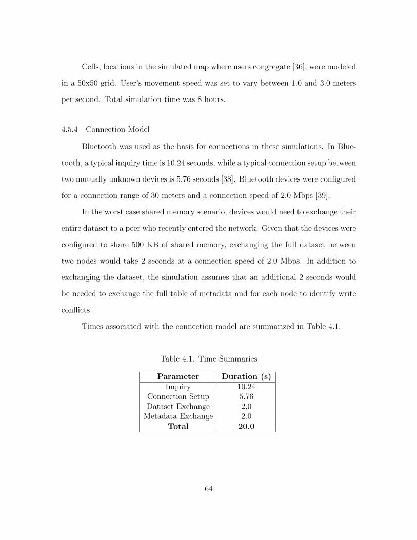
Cells, locations in the simulated map where users congregate [36], were modeled
in a 50x50 grid. User’s movement speed was set to vary between 1.0 and 3.0 meters
per second. Total simulation time was 8 hours.
4.5.4 Connection Model
Bluetooth was used as the basis for connections in these simulations. In Blue-
tooth, a typical inquiry time is 10.24 seconds, while a typical connection setup between
two mutually unknown devices is 5.76 seconds [38]. Bluetooth devices were configured
for a connection range of 30 meters and a connection speed of 2.0 Mbps [39].
In the worst case shared memory scenario, devices would need to exchange their
entire dataset to a peer who recently entered the network. Given that the devices were
configured to share 500 KB of shared memory, exchanging the full dataset between
two nodes would take 2 seconds at a connection speed of 2.0 Mbps. In addition to
exchanging the dataset, the simulation assumes that an additional 2 seconds would
be needed to exchange the full table of metadata and for each node to identify write
conflicts.
Times associated with the connection model are summarized in Table 4.1.
Table 4.1. Time Summaries
Parameter Duration (s)Inquiry 10.24
Connection Setup 5.76Dataset Exchange 2.0
Metadata Exchange 2.0Total 20.0
64

Based on these values, two nodes in the movement model must be within 30
meters of one another for at least 20 seconds to consider the connection viable for
utilization.
4.5.5 DTLRC Configuration
Each device was configured with 500KB of shared memory, divided into 62,500
indices, or roughly 8 bytes per index. Writes are uniformly distributed across shared
memory, and occur every five to fifteen minutes. Each of the simulated devices share
writes with every other device. Each of the shared memory scenarios were run a total
of 30 times, and the results of the trials compared here.
4.5.6 Comparison to Extant DSM Systems
Performing an effective comparison between DTLRC and existing systems presents
several challenges. As stated previously, opportunistic networks are suitable only for
delay tolerant applications. Common performance metrics, such as response time,
would therefore not be an appropriate measurement in this environment.
Furthermore, application performance in opportunistic networks is heavily de-
pendent on the connectivity between nodes. Some metrics, such as throughput, would
be less indicative of a system’s performance, and more a reflection on the underlying
mobility patterns of nodes.
In an attempt to provide a one-to-one comparison between DTLRC and sim-
ilar systems, two variations of DTLRC were simulated. These variations are not
being proposed for implementation, but are simulated to provide a simple baseline
comparison.
These variations used static nodes, arranged in a basic grid over the simulation
area, as depicted in figure 4.3. A grid layout was used for simplicity, as arranging an
65

50
0m
500m
100m
Static
Node
Broadcast
Radius
Figure 4.3. Static Node Simulation Area Layout.
optimal circle packing is non-trivial. WiFi was used as the connection medium, with
a range of 100m. Requirements to count as a viable opportunistic contact following
specifications outlined in §4.5.4. In simulations with static nodes (“static simulations”
for brevity), mobile nodes could only communicate with static nodes, and not with
other mobile nodes. Static simulations were configured in two modes:
1. Connected : Static nodes were connected to one another and could share data
between themselves, as well as mobile nodes; and,
2. Disconnected : Static nodes could only share writes with mobile nodes, and not
directly with other static nodes.
The number of static nodes was sequentially incremented from one to nine.
Nine nodes became the upper bound as their combined broadcast radii effectively
66

covered the entire simulation area. Due to space requirements, results from vary-
ing the number of static nodes have been amalgamated to demonstrate rudimentary
trends.
4.5.7 Metrics
To illustrate the performance of DTLRC, the following metrics were recorded
in each simulation and analyzed.
4.5.7.1 State
State measures how many different versions of shared memory exist in the
system. As processes produce writes to shared memory, the number of different
copies of memory in the system will increase. As nodes meet and share their writes,
the number of versions decreases as memory is made consistent.
State is divided into three categories: vicinity-based, random sample and over-
all.
• Vicinity-based : A comparison of the shared memory of a set of nodes within
relatively close physical proximity. This implies the sampled nodes have:
– Recently had an opportunistic contact with one another;
– Are likely to have an opportunistic contact in the near future; or,
– Both.
Vicinity-based is an index-by-index comparison. The number of individual in-
dices that are different is recorded;
• Random sample: A comparison of the shared memory of a set of randomly
selected nodes from across the network. Selected nodes may or may not be
within one anothers immediate physical vicinity. Like vicinity-based state, ran-
dom sample is an index-by-index comparison; and,
67

• Overall state: A count of the number of nodes in the system with a unique
state of memory. In this metric, a node is considered to have a unique state of
memory when one or more indices are different.
Tracking the state will give insight into the cycles of divergence and convergence
of the contents of shared memory.
4.5.7.2 Writes Exchanged and Write Conflicts
To illustrate the total flow of data through the system, as well as the subse-
quential write conflicts, the following metrics are recorded:
• Writes Exchanged (WE): The average total, average mean and average maxi-
mum number of writes exchanged per trial;
• Write Conflicts (WC): The average total, average maximum and average min-
imum number of write conflicts per trial; and,
• Time to Convergence (TTC): The interval between the first occurrence of a
write conflict at a specific index and the last occurrence of a write conflict at
that index. The last occurrence of a write conflict at a specific index indicates
one of two things:
– No instance of the conflicting write exists in the shared memory of any
node in the network; or,
– The different values for writes at this index never fully converge at all
nodes in the network. This is the number of unresolved write conflicts
(UWC) per trial.
The average number of unresolved write conflicts, the average mean TTC and
the average maximum TTC are recorded per trial.
68

While the number of writes exchanged can be closely tied to the rate of op-
portunistic contacts occurring in the network, the results help depict what would be
expected from DTLRC’s deployment in the real world.
4.6 DTLRC Simulation Results
Results from the DTLRC simulations are presented here.
4.6.1 State Results
This section discusses the state results, as outlined in §4.5.7.1.
4.6.1.1 Vicinity-based Versus Random Sample
Figures 4.4 through 4.11 show the results for both random sampling and vicinity-
based sampling. Due to space requirements, the results from sequentially increas-
ing the number of static nodes have been amalgamated to demonstrate overarching
trends.
0 0.5 1 1.5 2 2.5
x 104
0
50
100
150
Time (s)
Nu
mb
er o
f D
iffe
rin
g I
nd
ices
Standard
Connected
Disconnected
Figure 4.4. Random: 10 Nodes.
0 0.5 1 1.5 2 2.5
x 104
0
1
2
3
4
5
6
Time (s)
Nu
mb
er o
f D
iffe
rin
g I
nd
ices
Standard
Connected
Disconnected
Figure 4.5. Vicinity-based: 10 Nodes.
69

0 0.5 1 1.5 2 2.5
x 104
0
50
100
150
200
Time (s)
Num
ber
of
Dif
feri
ng I
ndic
es
Standard
Connected
Disconnected
Figure 4.6. Random: 25 Nodes.
0 0.5 1 1.5 2 2.5
x 104
0
1
2
3
4
5
6
7
8
Time (s)
Num
ber
of
Dif
feri
ng I
ndic
es
Standard
Connected
Disconnected
Figure 4.7. Vicinity-based: 25 Nodes.
0 0.5 1 1.5 2 2.5
x 104
0
50
100
150
200
Time (s)
Num
ber
of
Dif
feri
ng I
ndic
es
Standard
Connected
Disconnected
Figure 4.8. Random: 50 Nodes.
0 0.5 1 1.5 2 2.5
x 104
0
2
4
6
8
10
12
14
Time (s)
Num
ber
of
Dif
feri
ng I
ndic
es
Standard
Connected
Disconnected
Figure 4.9. Vicinity-based: 50 Nodes.
Across the experiments, connected DTLRC displays a consistently low number
of differing memory content between nodes, relative to the other methods. This is
to be expected, as connected DTLRC distributes data across a large geographic area
without relying on the mobility of nodes to physically move data across the map.
However, when there are still a low number of static nodes, connected DTLRC will
display steadily increasing memory divergence across the network, unless all mobile
nodes move into a static node’s transmission range.
70

0 0.5 1 1.5 2 2.5
x 104
0
50
100
150
200
250
Time (s)
Num
ber
of
Dif
feri
ng I
ndic
es
Standard
Connected
Disconnected
Figure 4.10. Random: 100 Nodes.
0 0.5 1 1.5 2 2.5
x 104
0
5
10
15
20
Time (s)
Num
ber
of
Dif
feri
ng I
ndic
es
Standard
Connected
Disconnected
Figure 4.11. Vicinity-based: 100 Nodes.
The number of differing indices in disconnected DTLRC steadily increases in
the random sample, as static nodes cannot share data unless a mobile node carries it
to them. As HCMM has no requirement that all nodes move to all parts of the map
[36], writes to memory become isolated where mobile nodes travel most often.
In standard DTLRC, the number of differing indices remain relatively consistent
throughout all of the trials. The indicated memory divergence of standard DTLRC
indicates that the system is scalable in the number of participating nodes it can
accommodate, provided those nodes remain in the same general area.
4.6.1.2 Overall State
Figures 4.12 through 4.14 present the results of the overall state simulations. For
these simulations, even a single index of the 62,500 simulated indices being different
will result in the node being considered to have a distinct set of memory. The higher
the number, the more nodes share identical contents of memory at the sample time.
In the opening seconds of the simulation, all nodes are instantiated with the
same contents of memory. This aspect of DTLRC’s operation is discussed in §4.2.1.
After the opening seconds of the simulation, when nodes begin to write to their own
71

0 0.5 1 1.5 2 2.5
x 104
0
20
40
60
80
100
Time (s)
Nodes
wit
h I
denti
cal
Sta
te
10 Nodes
25 Nodes
50 Nodes
100 Nodes
Figure 4.12. Overall State: Standard.
0 0.5 1 1.5 2 2.5
x 104
0
20
40
60
80
100
Time (s)
Nodes
wit
h I
denti
cal
Sta
te
10 Nodes
25 Nodes
50 Nodes
100 Nodes
Figure 4.13. Overall State: Connected.
0 0.5 1 1.5 2 2.5
x 104
0
20
40
60
80
100
Time (s)
Nodes
wit
h I
denti
cal
Sta
te
10 Nodes
25 Nodes
50 Nodes
100 Nodes
Figure 4.14. Overall State: Disconnected.
copy of memory and share that content with peers, the number of nodes with identical
contents of memory drops. Connected DTLRC trends with a higher number of nodes
with complete coherence of memory at any sample time. This is because as long as a
mobile node is within any static node’s broadcast radius, its updates to memory will
be exchanged to all other nodes within any static node’s transmission range.
Disconnected DTLRC results in fewer nodes having identical views of memory,
as each static node becomes an isolated pool of data. The static nodes are dependent
on mobile nodes to act as the medium facilitating the exchange of write objects.
72
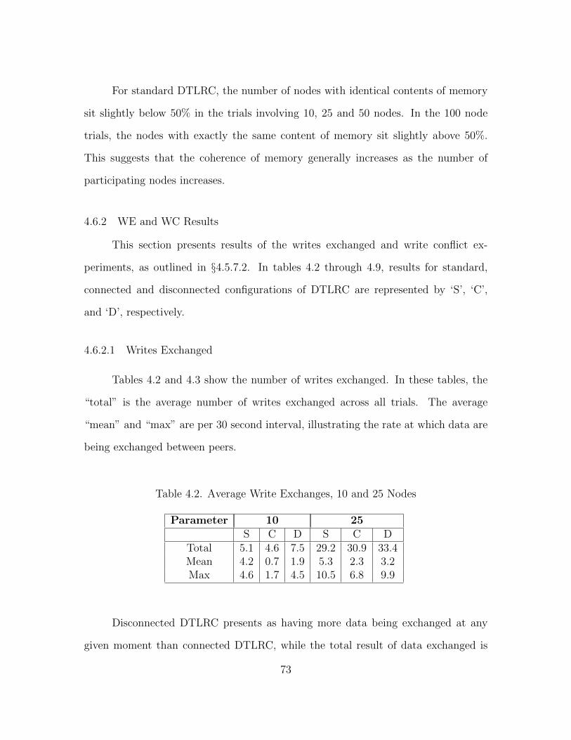
For standard DTLRC, the number of nodes with identical contents of memory
sit slightly below 50% in the trials involving 10, 25 and 50 nodes. In the 100 node
trials, the nodes with exactly the same content of memory sit slightly above 50%.
This suggests that the coherence of memory generally increases as the number of
participating nodes increases.
4.6.2 WE and WC Results
This section presents results of the writes exchanged and write conflict ex-
periments, as outlined in §4.5.7.2. In tables 4.2 through 4.9, results for standard,
connected and disconnected configurations of DTLRC are represented by ‘S’, ‘C’,
and ‘D’, respectively.
4.6.2.1 Writes Exchanged
Tables 4.2 and 4.3 show the number of writes exchanged. In these tables, the
“total” is the average number of writes exchanged across all trials. The average
“mean” and “max” are per 30 second interval, illustrating the rate at which data are
being exchanged between peers.
Table 4.2. Average Write Exchanges, 10 and 25 Nodes
Parameter 10 25S C D S C D
Total 5.1 4.6 7.5 29.2 30.9 33.4Mean 4.2 0.7 1.9 5.3 2.3 3.2Max 4.6 1.7 4.5 10.5 6.8 9.9
Disconnected DTLRC presents as having more data being exchanged at any
given moment than connected DTLRC, while the total result of data exchanged is
73
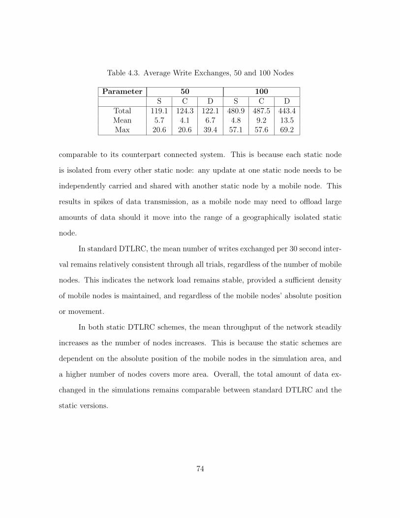
Table 4.3. Average Write Exchanges, 50 and 100 Nodes
Parameter 50 100S C D S C D
Total 119.1 124.3 122.1 480.9 487.5 443.4Mean 5.7 4.1 6.7 4.8 9.2 13.5Max 20.6 20.6 39.4 57.1 57.6 69.2
comparable to its counterpart connected system. This is because each static node
is isolated from every other static node: any update at one static node needs to be
independently carried and shared with another static node by a mobile node. This
results in spikes of data transmission, as a mobile node may need to offload large
amounts of data should it move into the range of a geographically isolated static
node.
In standard DTLRC, the mean number of writes exchanged per 30 second inter-
val remains relatively consistent through all trials, regardless of the number of mobile
nodes. This indicates the network load remains stable, provided a sufficient density
of mobile nodes is maintained, and regardless of the mobile nodes’ absolute position
or movement.
In both static DTLRC schemes, the mean throughput of the network steadily
increases as the number of nodes increases. This is because the static schemes are
dependent on the absolute position of the mobile nodes in the simulation area, and
a higher number of nodes covers more area. Overall, the total amount of data ex-
changed in the simulations remains comparable between standard DTLRC and the
static versions.
74

4.6.2.2 Write Conflicts
Tables 4.4 through 4.5 show the number of write conflicts for 10, 25, 50 and
100 nodes. The values are the “average”, “maximum” and “minimum” total number
of write conflicts per trial.
Table 4.4. Write Conflicts, 10 and 25 Nodes
Parameter 10 25S C D S C D
Average 10.7 8.6 14.1 154.8 146.3 144.0Maximum 42 34 48 412 268 339Minimum 1 13 18 53 156 171
Table 4.5. Write Conflicts, 50 and 100 Nodes
Parameter 50 100S C D S C D
Average 1235.5 1180.9 1410.5 11321.2 9065.1 13062.9Maximum 1924 1667 6214 36488 11687 44888Minimum 710 1221 1614 6931 9297 23568
Here, connected DTLRC trends with the lowest number of write conflicts. This
is expected, as less memory divergence can materialize when data is so efficiently
spread across a large area.
Standard DTLRC provides comparable performance to connected DTLRC for
10, 25, and 50 nodes. The difference in the number of write conflicts becomes substan-
tial with 100 nodes. This suggests that the rate of opportunistic contacts allows more
nodes to receive data that is later conflicted. As discussed in §4.6.1.2, the coherence
of memory increases at the expense of resolving more write conflicts.
75

Disconnected DTLRC trends with a higher number of write conflicts than either
of the other systems, with exception of the 25 node trials. This is because isolated
static nodes can accumulate large amounts of conflicting data, which would have been
resolved earlier had the node had more regular contact with the rest of the network.
4.6.2.3 Time to Convergence
Tables 4.6 through 4.9 present the time to convergence results. The first row of
these tables is the average number of unresolved write conflicts existing at the very
end of the trial. The “average” and “minimum” are the average and minimum time
to the convergence of a write to an index in hours (h), minutes (m) and seconds (s),
respectively.
Table 4.6. Time to Convergence, 10 Nodes
Parameter 10S C D
UWCs 0.6 1.4 1.0Average 11m 9.6s 1m 7.4s 3m 46.3s
Maximum 18m 36.0s 1m 11.1s 2m 18.9s
Table 4.7. Time to Convergence, 25 Nodes
Parameter 25S C D
UWCs 5.7 6.3 3.5Average 10m 53.5s 5m 32.3s 8m 57.6s
Maximum 17m 51.9s 14m 21.1s 13m 30s
76

Table 4.8. Time to Convergence, 50 Nodes
Parameter 50S C D
UWCs 22.5 22.8 9.7Average 10m 22.8s 11m 34.3s 15m 54.3s
Maximum 1h 19m 27.3s 1h 30m 11.1s 40m 26.7s
Table 4.9. Time to Convergence, 100 Nodes
Parameter 100S C D
UWCs 85.9 91.4 47.9Average 10m 50.6s 20m 31.7s 20m 53.4s
Maximum 3h 33m 54s 3h 59m 14s 1h 55m 15.6s
With standard DTLRC, the average TTC remains relatively constant regardless
of the number of nodes in the network. This is another indication that the perfor-
mance of standard DTLRC remains consistent, regardless of the number of nodes in
the network.
The average TTC for both static variants increases with the number of mobile
nodes. This is because a greater number of mobile nodes present an elevated prob-
ability that any specific node will be outside the transmission radius of any of the
available static nodes. In this case, the mobile node must simply wait until it travels
to within a static node’s range before its writes can be shared and inconsistencies in
its memory be made coherent.
4.7 Social Cache Simulation
Social Cache simulations were performed with the same data sets generated for
the DTLRC simulations. In HCMM, varying the number of nodes affects the mobility
77

patterns of peers [36]. This being the case, a subset of four nodes which repeatedly
met during the simulation were selected as the hosts for Social Cache.
The underlying connection model utilized was the same as discussed in §4.5.4.
The following metrics were recorded:
• Write Conflicts (WC): The average total, average maximum and average min-
imum number of write conflicts per trial; and,
• Time to Fulfillment (TTF): The interval between a peer’s request for the data
at a specific index, and that request being fulfilled by the owner of that index.
The average, maximum and minimum TTF were recorded.
4.8 Social Cache Results
Table 4.10 presents the Social Cache simulation results. The following times
are presented in hours (h), minutes (m) and seconds (s). Presented “maximums” and
“minimums” are absolute, not average.
Table 4.10. Time to Fulfillment Summary
Parameter 10 25 50 100Average 19m 2s 20m 11s 30m 20s 16m 37s
Maximum 6h 55m 40s 5h 15m 35s 6h 27m 44s 4h 49m 19sMinimum 0s 0s 0s 0s
In the worst case, requests for data were not filled within half the simulated
time span. However, most requests for data were filled in less than half an hour.
The minimum times for each simulated set were all 0 seconds, indicating that the
requesting peer had an open connection with the source peer at the time the request
was made.
78

The number of write conflicts recorded during the Social Cache experiments
were trivial, often zero and never more than 10.
4.9 Conclusion
This section presents Delay Tolerant Lazy Release Consistency and Social Cache
as methodologies for maintaining the consistency of shared data in opportunistic net-
works. Simulation results demonstrate that DTLRC and SC are viable technologies
in a variety of scenarios where opportunistic contacts occur among wireless devices.
Future work on DTLRC and SC would include:
• Introduce additional conflict resolution protocols that allow shared data to reach
a meaningful, consistent state while remaining generic enough to be utilized by
an assortment of applications;
• Adapt DTLRC and SC for utilization across multiple hops with an ON;
• Explore potential issues and solutions relating to the security of DTLRC and
SC; and,
• Implement fault tolerance should a node in a SC system be permanently dis-
connected from its peers.
The presented issues, as well as others, can increase an itinerant wireless device’s
ability to effectively collaborate and share content with peers.
79

CHAPTER 5
AN ANALYTICAL MODEL FOR DTLRC
DTLRC is a robust protocol for the implementation of distributed shared mem-
ory within opportunistic networks. While the algorithm enables DTLRC to function
in the most challenged of networking environments, the inherent complexity of the
protocol limits its accessibility to developers. To better facilitate insight into the
performance of DTLRC, an analysis model is desirable.
5.1 Introduction
The central element of DTLRCs functionality springs from the following essen-
tial concepts:
• Shared memory is indexed;
• The organization and division of memory are identical across all participating
platforms; and,
• The system attains consensus by finding the most appropriate content for each
index. Once the most appropriate content is identified, it is shared across all
participating nodes.
No association between indices is inferred unless a set of indices is assigned to a
cluster, as discussed in §4.2.3. This means each individual index is independent, and
can be considered on its own.
The fundamental metric of the index is the number of nodes that share the same
state (e.g., value) for that index. This is the cardinality of the state set (CSS). Once
80

the evolution of CSS is successfully captured by the model DTLRCs performance can
be examined thoroughly.
CSS behavior is affected by two events:
• Two nodes have a meeting and share their contents of memory; and,
• A node writes to its local of memory.
In the former, CSS decreases as write conflicts are brought into consensus. In
the latter, CSS increases, as the new write breaks the consensus. Therefore, the two
parameters that change CSS are meet probability, and write probability.
Node 1 Node 2 Node 3Index 0
Index 1
Index 2
A A A CSS = 1
B B C CSS = 2
D E F CSS = 3
Node 1 Node 2 Node 3Index 0
Index 1
Index 2
A A A CSS = 1
B B B CSS = 1
D E E CSS = 2
Meet
Node 1 Node 2 Node 3Index 0
Index 1
Index 2
A A A CSS = 1
G B B CSS = 2
H E E CSS = 2
Write
t0
t1
t2
Figure 5.1. Index write sequence.
81
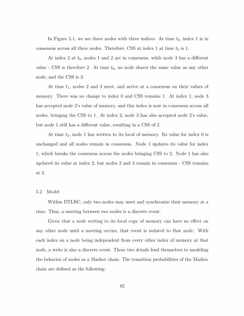
In Figure 5.1, we see three nodes with three indices. At time t0, index 1 is in
consensus across all three nodes. Therefore, CSS at index 1 at time t0 is 1.
At index 2 at t0, nodes 1 and 2 are in consensus, while node 3 has a different
value - CSS is therefore 2. At time t0, no node shares the same value as any other
node, and the CSS is 3.
At time t1, nodes 2 and 3 meet, and arrive at a consensus on their values of
memory. There was no change to index 0 and CSS remains 1. At index 1, node 3
has accepted node 2’s value of memory, and this index is now in consensus across all
nodes, bringing the CSS to 1. At index 2, node 3 has also accepted node 2’s value,
but node 1 still has a different value, resulting in a CSS of 2.
At time t2, node 1 has written to its local of memory. Its value for index 0 is
unchanged and all nodes remain in consensus. Node 1 updates its value for index
1, which breaks the consensus across the nodes bringing CSS to 2. Node 1 has also
updated its value at index 2, but nodes 2 and 3 remain in consensus - CSS remains
at 2.
5.2 Model
Within DTLRC, only two nodes may meet and synchronize their memory at a
time. Thus, a meeting between two nodes is a discrete event.
Given that a node writing to its local copy of memory can have no effect on
any other node until a meeting occurs, that event is isolated to that node. With
each index on a node being independent from every other index of memory at that
node, a write is also a discrete event. These two details lend themselves to modeling
the behavior of nodes as a Markov chain. The transition probabilities of the Markov
chain are defined as the following:
82

• Write probability: the probability that a node will write to its own copy of
memory;
• Meet probability: defined as 1− (WriteProbability); and,
• Write limit: the number of times a node may write to its own copy of memory
per consensus interval. A “consensus interval” is defined as the interval between
the contents of memory diverging, and the contents of memory again reaching
consensus.
5.2.1 Markov Chain
The evolution of memory contents is modeled as follows. There are three pos-
sible actions in this chain:
• A system may return to the same state, indicating that neither a meeting, nor
a write occurred. This leaves CSS unchanged;
• Two nodes may meet, and agree on the content of an index. This results in a
decreased CSS; or,
• A node may write to its local copy of memory. This increases the CSS.
As each event is discrete, CSS may increase or decrease by no more than 1.
An example Markov change is illustrated in Figure 5.2.
While the Markov chain does model the contents of memory over time, one
addition is necessary in order to make this a model for DTLRC. An additional marker
is needed to facilitate conflict resolution §(4.2.6).
5.2.2 Conflict Resolution
A critical aspect of DLTRC is its ability to resolve write conflicts by selecting
the most appropriate value to apply to memory in the event two or more nodes wrote
83

0, 0
1, 0 0, 2
1, 2
1, 1 2, 2
Start State
(Consensus)
CSS = 1
Write
(Divergence)
CSS = 2
Meeting
(Consensus)
CSS = 1
Figure 5.2. Two node Markov chain.
to the same index. For the Markov chain to model this, an additional value needs to
be added to record the write history.
A node’s current contents of memory are stored in the values 1 to n, where n
is the number of nodes. To ensure that overwritten values of memory are eventually
removed from the system, the Markov chain keeps the write history in value n + 1.
Stored in n + 1 is the ID of the most recent node to write to memory. In the
event of a conflict, the model will apply the most recent write to the meeting’s nodes.
84
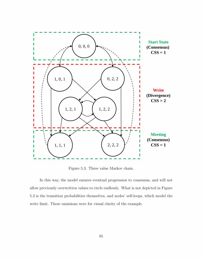
0, 0, 0
1, 0, 1 0, 2, 2
1, 2, 1
1, 1, 1 2, 2, 2
Start State
(Consensus)
CSS = 1
Write
(Divergence)
CSS = 2
Meeting
(Consensus)
CSS = 1
1, 2, 2
Figure 5.3. Three value Markov chain.
In this way, the model ensures eventual progression to consensus, and will not
allow previously overwritten values to circle endlessly. What is not depicted in Figure
5.3 is the transition probabilities themselves, and nodes’ self-loops, which model the
write limit. These omissions were for visual clarity of the example.
85

5.2.3 Algorithms
The main analysis loop works its way through a list of contacts recorded from
HCMM, the identical list of meetings used for the original DTLRC simulation (Algo-
rithm 1). A random double is computed and compared to the parameter for meeting
probability. If the random value exceeds the meeting probability, then the simulator
processes a meeting. Otherwise, the simulator selects a node to write to its local copy
of memory.
Algorithm 1 Main Analysis Loop
1: while Contacts Available do2: if random.nextDouble() > Meeting Probability then3: meet();4: else5: write();6: end if7: end while
During a meeting, there are three possible scenarios (Algorithm 2):
1. First, the contents of memory of either node are identical. This could be because
neither node has written to memory yet or the nodes have met during the present
consensus interval and are already synchronized;
2. Second, one node may have updated its contents of memory, while the other
has not. In this case, the model shares the new write with the remote node,
and updates the write history; or,
3. Third, both nodes have different contents of memory. This indicates a write
conflict, and must be resolved with Algorithm 3.
During conflict resolution, the system examines the contents of nodes’ memory
against the present value of the write history. One node will necessarily have the
86

contents of the write history, and the other will not. Whichever node contains the
contents of write history shares its value with the remote node.
Algorithm 2 Node Meeting
. There are three cases. First, the memory contents of both nodes are equal inwhich case, there’s nothing to do.
if a.memV alue = b.memV alue thenreturn;
end if
. Second, one node may have an updated value while the other does not. If neitherhas updated memory, we’ve already returned above.
if a.memV alue = −1 thena.share(b.memValue);updateExchangeHistory(b.memValue);
else if b.memV alue = −1 thenb.share(a.memValue);updateExchangeHistory(a.memValue);
end if
. Otherwise, we have a write conflict that must be resolved by consulting the writehistory.
resolveConflict(a, b);
Following the above algorithms will eventually put all nodes into a consensus,
which starts a new consensus interval, and resets the write limit.
5.3 Evaluation
In order to provide a one-to-one comparison against the original DTLRC sim-
ulations, the same data traces produced by HCMM are used (§4.5.2). This means
the same nodes meet in the same order as the original trials. For the analysis, we
87

Algorithm 3 Conflict Resolution
. Here, one node has the current contents of the exchange history, and the othernode necessarily does not.
if a.memValue == exchangeHistory.get(0) thenb.share(a.memValue);updateExchangeHistory(a.memValue);
elsea.share(b.memValue);updateExchangeHistory(b.memValue);
end if
modeled 25 nodes, with a write probability between 5% and 60% at 5% intervals.
Write limits were set at 1, 2, and 3 respectively.
Figure 5.4 is presented first, for clarity. This is a histogram of CSS from the
original DLTRC data trace. The x-axis was the CSS value at the sample (there were
1000 samples, total). The y-axis is the number of times that CSS occurred in the data
trace. Notice that the x-axis in the following figures contains value 1 to n (n = 25 in
this case). This is because complete divergence of memory would mean that each of
25 nodes had its own unique value.
As we see from the original results of DLTRC, the CSS is predominantly 1 at
most sample intervals. This was due to the relatively low activity of memory with
the original simulations (§4.5.5).
Figure 5.5 show the original trace, overlapped with the results from write limit
1, and write probabilities 10% and 20% respectively.
It is immediately apparent that trace with a write limit of 1 and write prob-
ability of 10% closely correlates with the original trace to the original trace, never
displaying a CSS greater than 2, with the relative entropy between the two models
coming to 0.023. Write limit 1 with write probability 20% is less closely correlated,
occasionally displaying a CSS of 3, and a relatively entropy totalling 0.054. Additional
88
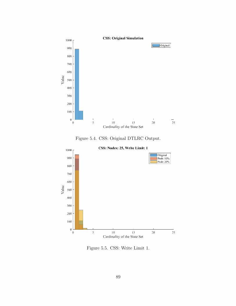
Figure 5.4. CSS: Original DTLRC Output.
Figure 5.5. CSS: Write Limit 1.
89

trials are not included, as the relative entropy increased linearly with the increase in
write probability.
Figure 5.6. CSS: Write Limit 2.
Figure 5.6 shows the original trace, overlapped with the results from write limit
2, and write probabilities 10% and 20% respectively. There is effectively no change
in the results from write probability 10%, with the relative entropy between it and
the original trace equaling 0.020. There is a change with write probability 20%, as its
CSS does occasionally equal 4, and the relative entropy between it and the original
trace increasing to 0.132.
Figure 5.7 presents the original trace, overlapped with results from write limit
3, and write probabilities 10% and 20%. There is effectively no change in the distri-
butions of either write probabilities, with relative entropies equaling 0.024 and 0.118.
90

Figure 5.7. CSS: Write Limit 3.
This indicates that a higher write limit only has an effect on the results of the model
at higher write probabilities.
5.4 Conclusion
This section presents a simplified model for characterizing the behavior of mem-
ory within DTLRC. This model is based on Markov chains, and presents a simplified
and scalable algorithm that captures the key parameters of DTLRC without the
onerous task of full implementation of the actual protocol.
Future work could include:
• Developing specific applications to model. The original parameters for DTLRC
were a rudimentary speculation on the behavior of a hypothetical application.
Memory behavior of actual applications in use would be especially helpful in
honing the model;
91

• Running large scale versions of the model to evaluate the model’s behavior when
used to simulate large scale systems with hundreds, if not thousands of nodes;
and,
• Collecting additional mobility models. The meet patterns of nodes are based
solely on the results from a mobility model. The creation of additional models
and experimentally collected data traces would help evaluate analysis.
92

CHAPTER 6
CONCLUSION
Mobile systems have become an omnipresent part of everyday life. As the
number of mobile systems continues to increase, the ability of devices to work together
will become even more important. Intermittent connection to networks will often be
seen as the rule, rather than the exception. Devices must still have the ability to
effectively collaborate, even when access to preexisting networking infrastructure is
an untenable prospect.
Numerous robust distributed system paradigms have been developed over the
years. However, all extant paradigms still rely on two assumptions: connections be-
tween computers on the network will be relatively stable, and that computers on that
network will ultimately be available. These assumptions are not always applicable in
mobile networks, but regardless, devices still must have feasible ways of employing
distributed system paradigms.
6.1 Summary of Contributions
This dissertation developed and evaluated three distributed system mechanisms
specifically tailored for use in opportunistic networks, and presented a simplified
analysis model to assist in gaining insight into one of those systems. The technical
contributions of the dissertation consistent of three components: DiTON, DTLRC,
and Social Cache. The simplified analysis model was developed for DTLRC.
DiTON is a protocol for executing a sequence of actions across multiple nodes
which must be completed successfully, or terminate with no changes to memory. Di-
93

TON allows for complex transactions, and ensures a consistent and expected outcome,
regardless of networking conditions.
DTLRC is a distributed shared memory protocol tailored for use in opportunis-
tic networks. DTLRC allows mobile systems to arrive at a consensus of memory
contents utilizing only pair-wise connections between devices. Using DTLRC, a sys-
tem may arbitrarily depart and join networks with no interruption of functionality.
Upon rejoining a network, DTLRC will ensure that any data produced during the
network partition will eventually be propagated, and appropriately applied, to all
participating systems.
Social Cache allows a collection of nodes with a high probability of repeatedly
encountering one another to increase the perceived capacity of shared memory. Social
Cache utilizes DTLRC as the underlying protocol to implement a scheme which more
closely resembles the behavior of extant distributed system paradigms.
An analytical model for DTLRC is developed in order to provide a simplified
way of gaining insight into DTLRCs performance without requiring a full implemen-
tation of the protocol. This model produces results closely correlated with DTLRC,
and is sufficiently scalable so that proposed systems of any size can be simulated with
relative ease.
6.2 Applications
DiTON and DTLRC can be employed anytime anywhere in the absence of
networking infrastructure. Reasons for not using infrastructure could include the
network being disabled, unable to cope with user demand, too costly to utilize, not
present, or simply unnecessary. Smartphones, autonomous vehicles, devices within
the IoT, and numerous other itinerant platforms can all make use of the work in this
dissertation.
94

6.3 Future Directions
This dissertation motivates future research in a number of areas. This work
presents an initial step towards implementing distributed system paradigms in signif-
icantly challenged networks.
Security issues were not taken into consideration while developing these pro-
tocols. Any scheme intended for use in opportunistic networks presents significant
challenges in ensuring the confidentiality, integrity, and access of data transiting that
network. Securing these protocols would be critical to ensuring their successful ap-
plication in the real world.
DiTON has a commit phase of transaction execution, but the precise commit
protocol is not specified. Additional work should determine an appropriate commit
sequence, whether two-phase, three-phase, or some novel scheme. Deadlock detection
is another important area of transaction completion that is not covered here. Proving
the completeness of a deadlock detection scheme can be an extraordinarily complex
process, and would result in a significant body of work in and of itself.
Additional conflict resolution protocols are an avenue of investigation in DT-
LRC and SC. While application specific resolution is intended to be added by im-
plementing developers, any scheme that would result in coherent, meaningful data
while remaining generically applicable to a wide spectrum of end users is desirable.
Permanently disconnecting from peers is always a possibility within ONs, and this
presents an issue to nodes utilizing SC. Future work in the are should address SC’s
behavior in the event of irreconcilable network partition.
Mathematical means for computing memory state could be formulated for the
DTLRC analysis model. Closed formed solutions for determining memory state at
an arbitrary time would remove the necessity of executing the full model, and would
be especially useful for simulating large networks.
95

REFERENCES
[1] The AllSeen Alliance. Open source iot to advance the internet of everything.
Accessed: October 15th, 2014. [Online]. Available: https://allseenalliance.org/
[2] S. Jain, K. Fall, and R. Patra, “Routing in a delay tolerant network,” SIGCOMM
Comput. Commun. Rev., vol. 34, pp. 145 – 158, Aug. 2004.
[3] L. Pelusi, A. Passarella, and M. Conti, “Opportunistic networking: Data for-
warding in disconnected mobile ad hoc networks,” IEEE Commun. Mag., vol. 44,
no. 11, pp. 134 – 141, Nov. 2006.
[4] M. Conti and M. Kumar, “Opportunities in opportunistic computing,” IEEE
Computer, vol. 43, no. 1, pp. 42 – 50, Jan. 2010.
[5] W. Zhao, M. Ammar, and E. Zegura, “A message ferrying approach for data de-
livery in sparse mobile ad hoc networks,” in Proceedings of the 5th ACM Interna-
tional Symposium on Mobile Ad Hoc Networking and Computing, ser. MobiHoc
’04. New York, NY, USA: ACM, 2004, pp. 187 – 198.
[6] W. Stallings, Wireless Communications and Networks, 2 ed. Upper Saddle
River, NJ, USA: Prentice Hall, 2005.
[7] G. Coulouris, J. Dollimore, T. Kindberg, and G. Blair, Distributed Systems:
Concepts and Design, 5 ed. Boston, MA, USA: Addison-Wesley, 2012.
[8] B. Lampson, “Atomic transactions,” in Distributed systems: Architecture and
Implementation. Vol 105 of Lecture Notes in Computer Science, vol. 2. Springer-
Verlag, 1981, pp. 254 – 259.
[9] T. Harder and A. Reuter, “Principles of transaction-oriented database recovery,”
ACM Computer Surveys, vol. 15, no. 4, 1983.
96

[10] B. Liskov, “Distributed programming in argus,” Communications of the ACM,
vol. 31, no. 3, pp. 300–312, 1988.
[11] S. Shrivistava, G. Dixon, and G. Parrington, “An overview of the arjuna dis-
tributed programming system,” IEEE Software, vol. 8, no. 1, pp. 66–73, 1991.
[12] J. Mitchell and J. Dion, “A comparison of two network-based file servers,” vol. 25,
no. 4, pp. 233–245, 1982.
[13] Q. Lu and M. Satyanaranyanan, “Isolation-only transactions for mobile comput-
ing,” SIGOPS Oper. Syst. Rev., vol. 28, no. 2, pp. 81–87, Apr. 1994.
[14] M. Satyanarayanan, “Coda: a highly available file system for a distributed work-
station environment,” in Workstation Operating Systems, 1989., Proceedings of
the Second Workshop on, Sep 1989, pp. 114–116.
[15] E. Pitoura and B. Bhargava, “Data consistency in intermittently connected dis-
tributed systems,” Knowledge and Data Engineering, IEEE Transactions on,
vol. 11, no. 6, pp. 896 –915, Dec. 1999.
[16] V. Kumar, N. Prabhu, M. H. Dunham, and A. Y. Seydim, “Tcot-a timeout-based
mobile transaction commitment protocol,” IEEE Transactions on Computers,
vol. 51, no. 10, pp. 1212–1218, Oct 2002.
[17] P. Bernstein, V. Hadzilacos, and N. Goodman, Concurrency Control and Recov-
ery in Database Systems. Reading, MA, USA: Addison-Wesley, 1987.
[18] P. Serrano-Alvarado, C. Roncancio, and M. Adiba, “A survey of mobile transac-
tions,” Distrib. Parallel Databases, vol. 16, no. 2, pp. 193 –230, Sep. 2004.
[19] B. Ayari, A. Khelil, and N. Suri, “On the design of perturbation-resilient atomic
commit protocols for mobile transactions,” ACM Trans. Comput. Syst., vol. 29,
no. 3, pp. 7:1–7:36, Aug. 2011.
97

[20] ——, “Partac: A partition-tolerant atomic commit protocol for manets,” in
Mobile Data Management (MDM), 2010 Eleventh International Conference on,
May 2010, pp. 135 –144.
[21] A. S. Tanenbaum and M. van Steen, Distributed Systems: Principles and
Paradigms, 2 ed. Upper Saddle River, NJ: Prentice Hall, 2006.
[22] A. Kshemkalyani and M. Singhal, Distributed Computing: Principles, Algorithms
and Systems. New York, NY, USA: Cambridge University Press, 2008.
[23] M. Wiesmann, F. Pedone, A. Schiper, B. Kemme, and G. Alonso, “Understand-
ing replication in databases and distributed systems,” in Distributed Computing
Systems, 2000. Proceedings. 20th International Conference on, 2000, pp. 464 –
474.
[24] L. Lamport, “How to make a multiprocessor computer that correctly executes
multiprocess programs,” IEEE Trans. Comput., vol. C-28, no. 9, pp. 690 – 691,
Sep. 1979.
[25] P. W. Hutto and M. Ahamad, “Slow memory: Weakening consistency to enhance
concurrency in distributed shared memories,” in Distributed Computing Systems,
1990. Proceedings., 10th International Conference on, May 1990, pp. 302 – 309.
[26] K. Gharachorloo, D. Lenoski, J. Laudon, P. Gibbons, A. Gupta, and J. Hennessy,
“Memory consistency and event ordering in scalable shared-memory multiproces-
sors,” in Computer Architecture, 1990. Proceedings., 17th Annual International
Symposium on, May 1990, pp. 15 – 26.
[27] C. Amza, A. Cox, S. Dwarkadas, P. Keleher, H. Lu, R. Rajamony, W. Yu,
and W. Zwaenepoel, “Treadmarks: shared memory computing on networks of
workstations,” Computer, vol. 29, no. 2, pp. 18 –28, feb 1996.
[28] P. Keleher, “Lazy release consistency for distributed shared memory,” Ph.D.
dissertation, Rice University, Houston, Texas, USA, 1994.
98

[29] Qualcomm Developer Network. Trepn profiler. Accessed: December
5th, 2014. [Online]. Available: https://developer.qualcomm.com/mobile-
development/increase-app-performance/trepn-profiler
[30] Qualcomm. Snapdragon mobile processors and chipsets — qual-
comm. Accessed: December 6th, 2014. [Online]. Available:
https://www.qualcomm.com/products/snapdragon
[31] CRAWDAD. A community resource for archiving wireless data at
dartmouth. Accessed: December 7th, 2014. [Online]. Available:
http://crawdad.cs.dartmouth.edu/index.html
[32] I. Rhee, M. Shin, S. Hong, K. Lee, S. Kim, and S. Chong, “CRAW-
DAD data set ncsu/mobilitymodels (v. 2009-07-23),” Downloaded from
http://crawdad.org/ncsu/mobilitymodels/, Jul. 2009.
[33] D. Stall and L. Stall. Antiqueweekend.com - texas antique weekend shows &
events - round top - warrenton - fayette county, tx. Accessed: February 6th,
2013. [Online]. Available: AntiqueWeekend.com
[34] U.S. Census Bureau, “2010 census,” U.S. Department of Commerce, Feb. 2011.
[35] T. Kelly, “Combinatorial auctions and knapsack problems,” Proceedings of the
Third International Joint Conference on Autonomous Agents and Multiagent
Systems, pp. 1278–1279, 2004.
[36] C. Boldrini and A. Passarella, “HCMM: Modelling spatial and temporal proper-
ties of human mobility driven by users social relationships,” Computer Commu-
nications, vol. 33, no. 9, pp. 1056–1074, Jun. 2010.
[37] C. Boldrini, M. Conti, F. Delmastro, and A. Passarella, “Context- and social-
aware middleware for opportunistic networks,” Journal of Network and Com-
puter Applications, vol. 33, no. 5, pp. 525–541, Sep. 2010.
99

[38] G. Chakraborty, K. Naik, D. Chakraborty, N. Shiratori, and D. Wei, “Analysis
of the bluetooth device discovery protocol,” Wirel. Netw., vol. 16, no. 2, pp.
421–436, Feb. 2010.
[39] Bluetooth Specification Version 2.1 + EDR [vol 0],
Bluetooth Special Interest Group (SIG), Jul. 2007,
https://www.bluetooth.org/docman/handlers/downloaddoc.
ashx?doc id=241363.
100

BIOGRAPHICAL STATEMENT
Chance Eary graduated from The University of Texas at Arlington with a B.S.,
M.S., and Ph.D. in Computer Science in 2009, 2011, and 2016, respectively. He was
the recipient of the U.S. Department of Education’s Graduate Assistance in Areas
of National Need Fellowship upon beginning work on his doctorate. His research
interests including distributed systems, networking, and information security.
101