distributed flow metering · proficy ®/cimplicity ... typical calibration workflow flow rate e...
TRANSCRIPT
Confidential. Not to be copied, distributed, or reproduced without prior approval. © 2017 Baker Hughes, a GE company, LLC - All rights reserved.
Distributed Flow Metering
October 25, 2018
SUT Down Under
Confidential. Not to be copied, distributed, or reproduced without prior approval.
• Why Distributed Flow Metering?
• What is Virtual Flow Metering, and how it works?
• What is the distributed flow metering solution?
• Concept Validation
Agenda
Confidential. Not to be copied, distributed, or reproduced without prior approval.
October 25, 2018 3
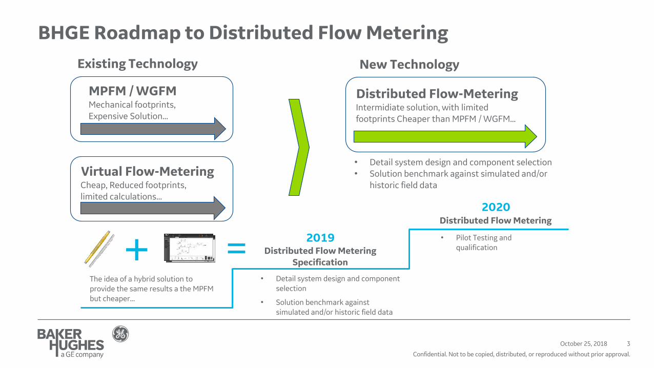
BHGE Roadmap to Distributed Flow Metering
Distributed Flow-MeteringIntermidiate solution, with limited footprints Cheaper than MPFM / WGFM...
MPFM / WGFMMechanical footprints,Expensive Solution...
Virtual Flow-MeteringCheap, Reduced footprints, limited calculations...
Existing Technology New Technology
• Detail system design and component selection• Solution benchmark against simulated and/or
historic field data
2019
The idea of a hybrid solution to provide the same results a the MPFM but cheaper...
• Detail system design and component selection
• Solution benchmark against simulated and/or historic field data
Distributed Flow Metering Specification
2020Distributed Flow Metering
• Pilot Testing and qualification
Confidential. Not to be copied, distributed, or reproduced without prior approval.
October 25, 2018 4
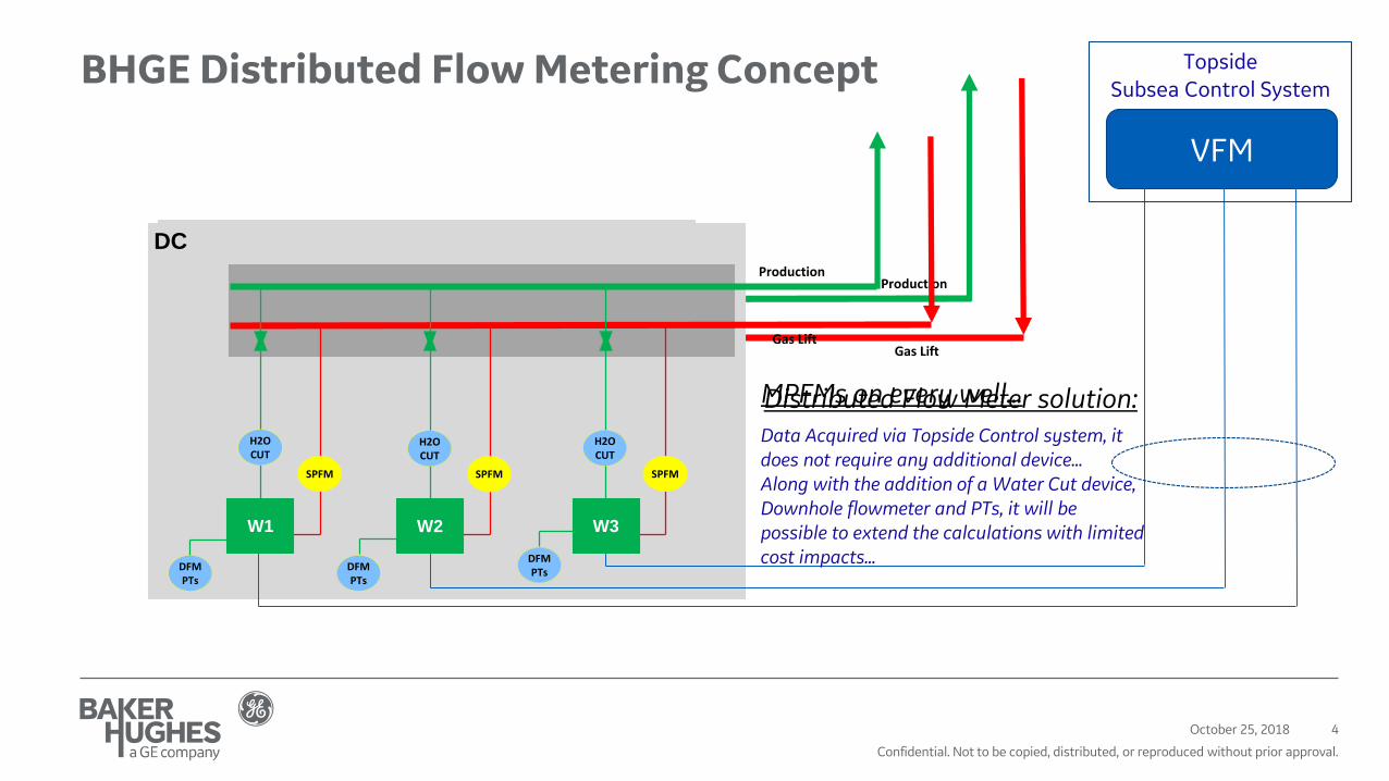
BHGE Distributed Flow Metering Concept
DC
Production
Gas Lift
MPFMs on every well…
SPFM
MPFM
W3
SPFM
MPFM
W1
SPFM
MPFM
W2
DC
Production
Gas Lift
VFM
SPFM
W3
SPFM
W2
SPFM
W1
Topside Subsea Control System
Distributed Flow Meter solution:Data Acquired via Topside Control system, it does not require any additional device…Along with the addition of a Water Cut device, Downhole flowmeter and PTs, it will be possible to extend the calculations with limited cost impacts…
H2OCUT
DFMPTs
DFMPTs
DFMPTs
H2OCUT
H2OCUT
Confidential. Not to be copied, distributed, or reproduced without prior approval.
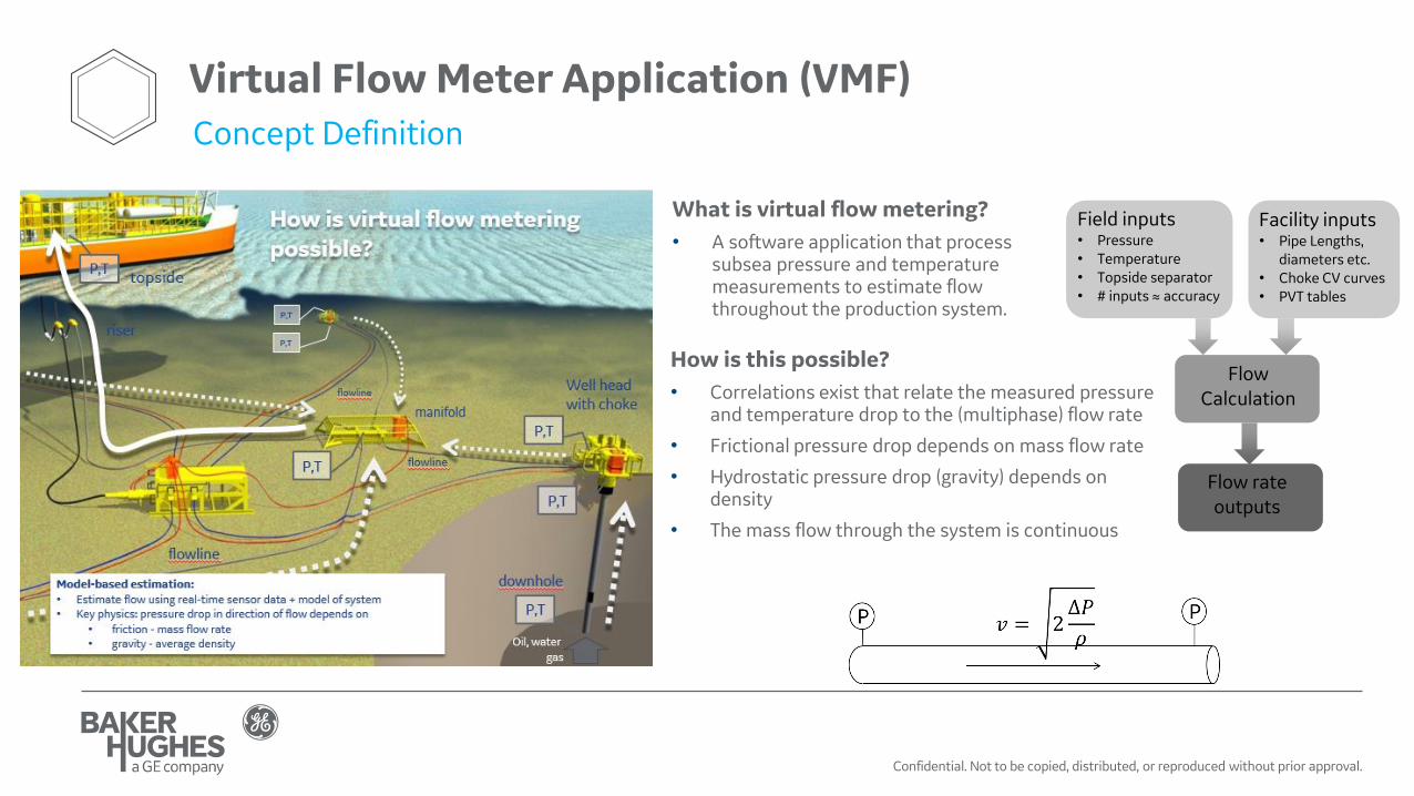
What is virtual flow metering?
• A software application that process subsea pressure and temperature measurements to estimate flow throughout the production system.
Field inputs• Pressure• Temperature• Topside separator• # inputs ≈ accuracy
Facility inputs• Pipe Lengths,
diameters etc.• Choke CV curves• PVT tables
Flow Calculation
Flow rate outputs
How is this possible?
• Correlations exist that relate the measured pressure and temperature drop to the (multiphase) flow rate
• Frictional pressure drop depends on mass flow rate
• Hydrostatic pressure drop (gravity) depends on density
• The mass flow through the system is continuous
Virtual Flow Meter Application (VMF)Concept Definition
Confidential. Not to be copied, distributed, or reproduced without prior approval.
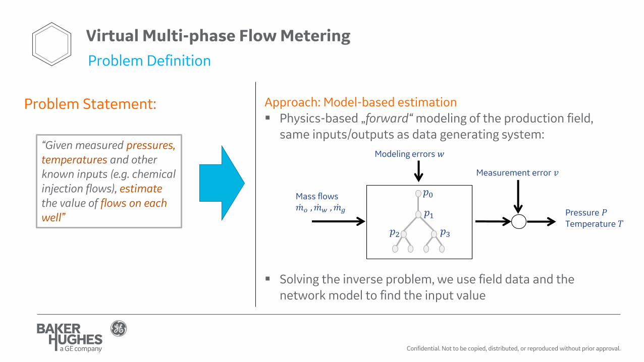
Virtual Multi-phase Flow Metering
Problem Definition
Approach: Model-based estimation▪ Physics-based „forward“ modeling of the production field,
same inputs/outputs as data generating system:
▪ Solving the inverse problem, we use field data and the network model to find the input value
“Given measured pressures, temperatures and other known inputs (e.g. chemical injection flows), estimate the value of flows on each well”
Mass flows ሶ𝑚𝑜 , ሶ𝑚𝑤 , ሶ𝑚𝑔 Pressure 𝑃
Temperature 𝑇
Measurement error 𝑣
𝑝1
𝑝0
𝑝2 𝑝3
Modeling errors 𝑤
Problem Statement:

Confidential. Not to be copied, distributed, or reproduced without prior approval.
Virtual Multi-phase Flow MeteringEstimation Algorithm
Estimator
Outputs:
- Well Flow rates- …
Flow Model:- TUFFP Unified Model- Beggs & Brill- Sachdeva/Perkins (chokes)- …
Heat Transfer Model:- Multi-Phase Models- …
PVT Models:- Compositional Models (PVTsim)- Black Oil Models- …
Inputs:
- P/Ts- …
Estimated Inputs:
- P/Ts- …
The VFM estimator optimises the relationship between P/T Drop Vs. Flow rate

Confidential. Not to be copied, distributed, or reproduced without prior approval.
• Network model consists of ‘pressure loss segments’ (PLS)• eg. pipes, chokes, venturi etc.
• Industry standard flow correlations are used on all pressure loss segments
• Flow rates are calculated for each well. Calculation engine minimises the error between measured pressures & temperatures
• Implemented as Recursive Estimator
Network Model Analytics
Virtual Multi-phase Flow Metering

Confidential. Not to be copied, distributed, or reproduced without prior approval.
Sensor Data
• Pressure and Temperature sensors
• Choke Position Sensors
• MPFM sensors (if available)
• Separator flows and pressure / temperatures
(if available)
Legend:
1) TOP_DPT1 = Sensor downstream of topside
choke
2) TOP_UTP1 = Sensor upstream of topside choke
3) AND_PLEM_DPT1 = Sensor at bottom of riser
4) KDC_DPT = Manifold header sensor
5) W1_DPT = Sensor downstream choke @ W1
6) W1_UPT = Sensor upstream choke @ W1
7) W1_DHT = Downhole sensor @ W1
8) W2_DPT = Sensor downstream choke @ W2
9) W2_UPT = Sensor upstream choke @ W2
10)W2_DHT = Downhole sensor @ W2
11)W3_DPT = Sensor downstream choke @ W3
12)W3_UPT = Sensor upstream choke @ W3
13)W3_DHT = Downhole sensor @ W3
Field/Geometry Data:
In addition to sensor data, the following data is
also required for each simulation:
Pipe Data:
• Pipe Profile: measurement depths Vs. true vertical depths
• Pipe Diameter (for all segments along the pipe)• Relative roughness (for all segments along the
pipe)• Ambient Temperature (for all segments along
the pipe)• Heat transfer boundary condition (for all
segments along the pipe)
Choke Data:
• Choke CV curve
PVT data:
• Fluid properties, phase envelope, etc (e.g. PVT tab file)
Virtual Flow Meter Application (VMF)Data Structure

Confidential. Not to be copied, distributed, or reproduced without prior approval.
October 25, 2018 10
Distributed Multi-phase Flow Metering
PT/TT
PT/TT
PT/TTPT/TT
%
WCM
PT/TT
PT/TT
PT/TT
%
PCV
GLCV
GLFM
Distributed Flow Meter additional Instruments
Virtual Flow Meter Instruments
P/T gauge
Water Sampling DeviceP/T Upstream Choke ValveP/T Downstream Choke ValveProduction choke valve positionGas Lift P/Ts & choke valve position
Downhole Venturi
Other Distributed Measurements (P/Ts, WC, flows, etc)
The main benefits of this solution are:
• Removal of MPFM/WGFM(Reduced cost & weight of subsea structures)
• Improved lead times(compared to WGFMs/MPFMs)
Other benefits include:
• Matching outputs to MPFM/WGFM technology (including water fraction and salinity measurements),
• Zonal allocation capabilities
• Reduced HSE exposure (e.g. avoidance of radioactive sources used in other technologies).
Water Cut Meter:• Water Fraction• Salinity

Confidential. Not to be copied, distributed, or reproduced without prior approval.
Key features
• Flow assurance & well performance tool✓ Steady-state 3 phase estimator
• Flow & phase fraction estimate at any point in production gathering network
• Integrated into Topside Control System
• Uses University of Tulsa TUFFP Flow Correlations
• Automatic reconcilliation of subsea flow to match topside separator measurements
• Offline maintenance and tuning✓ Remote connectivity to GE operative✓ Access to authorised users
• Low cost metering solution for well performance
• Straightforward Calibration/Tuning
• Robust to instrumentation failure – “Graceful Degradation”✓ as sensors fail, the VFM tolerance
increases but will still provide distributed field measurements.
• Advanced Trending & Reporting using PROFICY®/CIMPLICITY
Distributed Multi-phase Flow MeteringKey Features
Confidential. Not to be copied, distributed, or reproduced without prior approval.
October 25, 2018 12
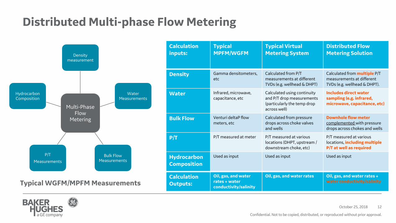
Distributed Multi-phase Flow Metering
Typical WGFM/MPFM Measurements
Multi-Phase Flow
Metering
Density measurement
Water Measurements
Bulk Flow Measurements
P/T
Measurements
Hydrocarbon Composition
Calculation inputs:
Typical MPFM/WGFM
Typical Virtual Metering System
Distributed Flow Metering Solution
Density Gamma densitometers, etc
Calculated from P/T measurements at different TVDs (e.g. wellhead & DHPT)
Calculated from multiple P/T measurements at different TVDs (e.g. wellhead & DHPT).
Water Infrared, microwave, capacitance, etc
Calculated using continuity and P/T drop measurements (particularly the temp drop across well)
Includes direct water sampling (e.g. infrared, microwave, capacitance, etc)
Bulk Flow Venturi deltaP flow meters, etc
Calculated from pressure drops across choke valves and wells
Downhole flow meter complemented with pressure drops across chokes and wells
P/T P/T measured at meter P/T measured at various locations (DHPT, upstream / downstream choke, etc)
P/T measured at various locations, including multiple P/T at well as required
Hydrocarbon Composition
Used as input Used as input Used as input
Calculation Outputs:
Oil, gas, and water rates + water conductivity/salinity
Oil, gas, and water rates Oil, gas, and water rates + water conductivity/salinity

Confidential. Not to be copied, distributed, or reproduced without prior approval.
Software ArchitectureOn-Premise & Cloud Solutions
CIMPLICITY Client
Application Server Historian Reporting Server
Smart Facility
Data Inputs
DCS / MCS
Remote Access
Operation Interface
Local User
Smart toolsGateway applicationSubsea data

Confidential. Not to be copied, distributed, or reproduced without prior approval.
Smart FacilitiesUser Experience
Confidential. Not to be copied, distributed, or reproduced without prior approval.
Concept Validation
October 25, 201815

Confidential. Not to be copied, distributed, or reproduced without prior approval.
Model ValidationPerformance against 3rd Party transient simulations - Tests Flow Diagram
VFM Calculation Engine Flow Diagram Flow Diagram for Fabrication of Transient Data
Confidential. Not to be copied, distributed, or reproduced without prior approval.
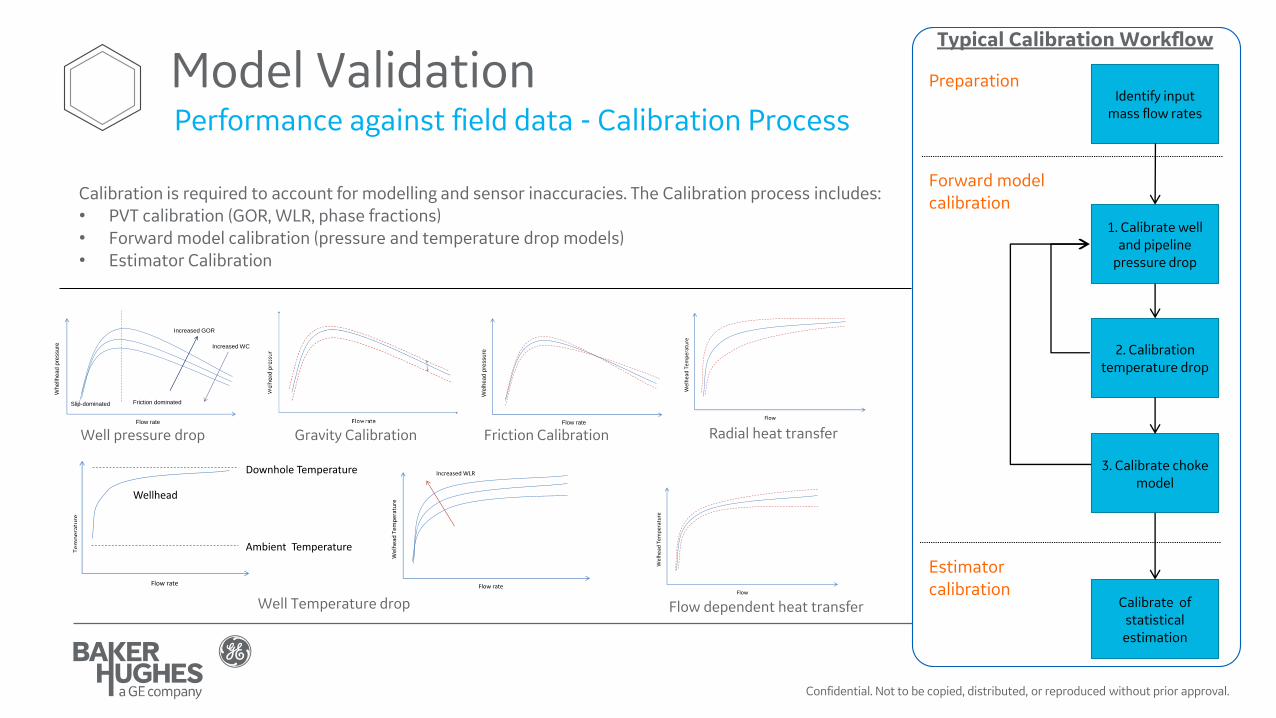
Model ValidationPerformance against field data - Calibration Process
1. Calibrate well and pipeline
pressure drop
2. Calibration temperature drop
3. Calibrate choke model
Calibrate of statistical estimation
Forward model calibration
Estimator calibration
PreparationIdentify input
mass flow rates
Typical Calibration Workflow
Flow rate
Wh
ellh
ea
d p
ressure
Slip-dominated
Increased GOR
Increased WC
Friction dominated
Well pressure drop Gravity Calibration
Flow rate
We
lhea
d p
ressu
re
Friction Calibration
Flow rate
Tem
per
atu
re
Flow rate
Wel
hea
d T
emp
erat
ure
Increased WLR
Well Temperature drop
Flow
Wel
hea
d T
emp
erat
ure
Flow
Wel
hea
d T
emp
erat
ure
Flow dependent heat transfer
Radial heat transfer
Calibration is required to account for modelling and sensor inaccuracies. The Calibration process includes:• PVT calibration (GOR, WLR, phase fractions)• Forward model calibration (pressure and temperature drop models)• Estimator Calibration

Confidential. Not to be copied, distributed, or reproduced without prior approval.
Virtual Flow Metering Test Campaign
October 25, 2018 18
Available Meassurements
VFM StudyP1 (without Gas Lift)
P4 (with Gas Lift)
S2 (with Gas Lift)
Phase 1 Choke DeltaPChoke DeltaTWell DeltaPWell DeltaT
Choke DeltaP (~100% open)Choke DeltaT (~100% open)Well DeltaPWell DeltaTGas Lift Venturi DeltaP
Choke DeltaP (~100% open)Choke DeltaT (~100% open)Well DeltaPWell DeltaTGas Lift Venturi DeltaP
Phase 2 + MPFM Venturi DeltaP + MPFM Venturi DeltaP + MPFM Venturi DeltaP
Phase 3 + Mixture Density+ P/T at MPFM
+ Mixture Density+ P/T at MPFM
+ Mixture Density+ P/T at MPFM
Phase 4 + Water Conductivity+ Salt Content
+ Water Conductivity+ Salt Content
+ Water Conductivity+ Salt Content
Phase 5 + Water Cut + Water Cut + Water Cut
Phase 6 + MPFM volumetric flow rates for First Year ONLY (to be used for tuning, deliverable is to re-run full time window)
+ MPFM volumetric flow rates for First Year ONLY (to be used for tuning, deliverable is to re-run full time window)
+ MPFM volumetric flow rates for First Year ONLY (to be used for tuning, deliverable is to re-run full time window)
Verification Phase + MPFM volumetric flow rates from Full Time Window
+ MPFM volumetric flow rates from Full Time Window
+ MPFM volumetric flow rates from Full Time Window
Confidential. Not to be copied, distributed, or reproduced without prior approval.
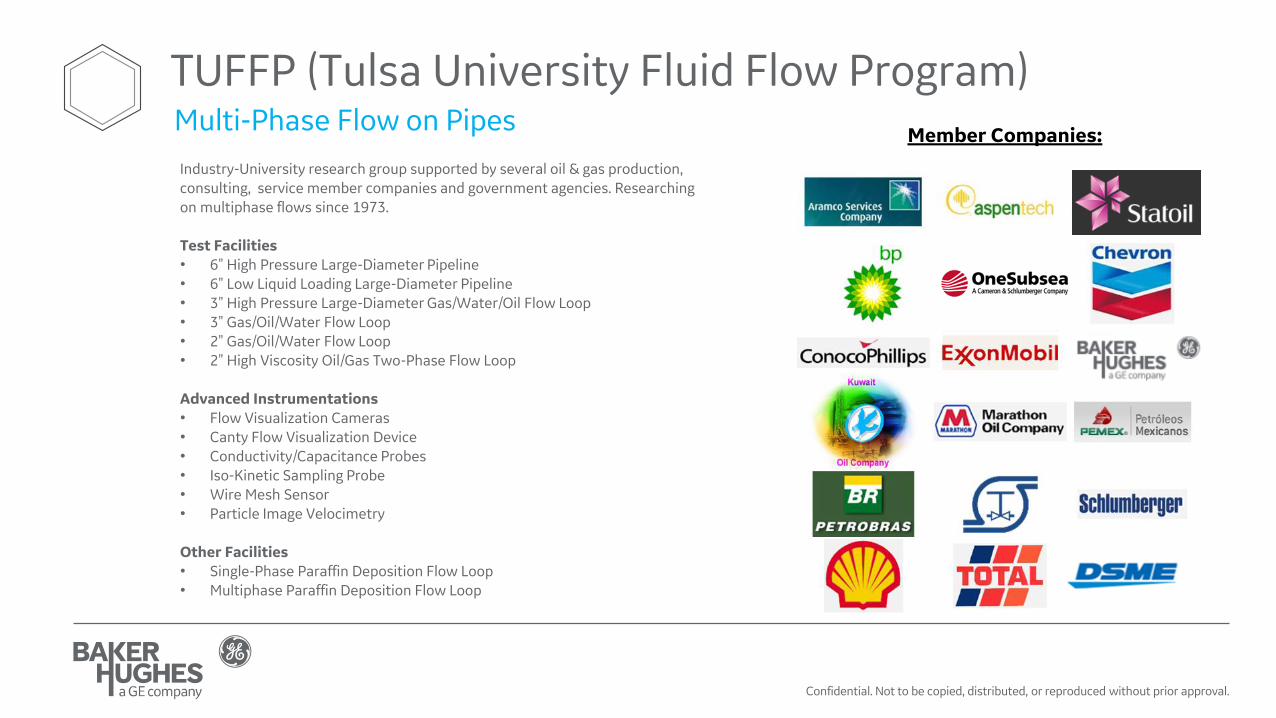
Member Companies:
Industry-University research group supported by several oil & gas production, consulting, service member companies and government agencies. Researching on multiphase flows since 1973.
Test Facilities• 6" High Pressure Large-Diameter Pipeline• 6" Low Liquid Loading Large-Diameter Pipeline• 3" High Pressure Large-Diameter Gas/Water/Oil Flow Loop• 3" Gas/Oil/Water Flow Loop• 2" Gas/Oil/Water Flow Loop• 2" High Viscosity Oil/Gas Two-Phase Flow Loop
Advanced Instrumentations• Flow Visualization Cameras • Canty Flow Visualization Device• Conductivity/Capacitance Probes• Iso-Kinetic Sampling Probe• Wire Mesh Sensor• Particle Image Velocimetry
Other Facilities • Single-Phase Paraffin Deposition Flow Loop• Multiphase Paraffin Deposition Flow Loop
TUFFP (Tulsa University Fluid Flow Program)Multi-Phase Flow on Pipes