distributed software system design representation using modified
TRANSCRIPT

IEEE TRANSACTIONS ON SOFTWARE ENGINEERING, VOL. SE-9, NO. 6, NOVEMBER 1983
[22] Z. Manna and P. Wolper, "Synthesis of communicating processesfrom temporal logic specifications," in Proc. Workshop Logics ofPrograms (Springer-Verlag Lecture Notes in Comput. Sci.), vol.131, 1981.
[23] S. Owicki and L. Lamport, "Proving liveness properties of con-current programs," ACM Trans. Programming Languages Syst.,vol. 4, pp. 455-495, July 1982.
[24] A. Pnueli, "The temporal semantics of concurrent programs," inSemantics of Concurrent Computation (Springer Lecture Notesin Comput. Sci.), vol. 70, June 1979, pp. 1-20.
[25] -, "On the temporal analysis of fairness," in Proc. 7th Annu.Symp. POPL, Jan. 1980, pp. 163-173.
[261 K. Ramamritham and R. M. Keller, "Specifying and provingproperties of sentinel processes," in Proc. 5th Int. Conf SoftwareEng., Mar. 1981, pp. 374-382.
[27] -, "On synchronization and its specification," in SpringerLecture Notes in Comput. Sci., vol. 111, June 1981.
[281 K. Ramamritham, "Specification and synthesis of synchronizers,"Ph.D. dissertation, Univ. Utah, Aug. 1981.
[29] H. A. Schmid, "On the efficient implementation of conditionalcritical regions and the construction of monitors," Act Infor-matica, vol. 6, pp. 227-249, 1976.
[30] R. L. Schwartz and P. M. Melliar-Smith, "Temporal logic specifi-cations of distributed systems," inProc. 2ndlnt. Conf DistributedSyst., Apr. 1981.
[31] A. C. Shaw, "Software specification languages based on regularexpressions," in Proc. Software Tools Workshop, May 1979, pp.1-39.
Krithivasan Ramamritham received the B.TechA degree in electrical engineering and the M.Tech
degree in computer science from the IndianInstitute of Technology, Madras, India, in 1976and 1978, respectively, and the Ph.D. degree incomputer science from the University of Utah,Salt Lake City, in 1981.Currently, he is an Assistant Professor in the
Department of Computer and InformationScience, University of Massachusetts, Amherst.His research interests include software engi-
neering, operating systems and distributed computing.Dr. Ramamritham is a member of the Association for Computing
Machinery and the IEEE Computer Society.
Robert M. Keller received the B.S. and M.S.E.E.degrees from Washington University, St. Louis,MO, and the Ph.D. degree from the Universityof California, Berkeley.Currently, he is a Professor of Computer
Science at the University of Utah, Salt LakeCity. From 1970-1976 he was an AssistantProfessor of Electrical Engineering at PrincetonUniversity. His current research interests dealwith numerous topics relating to multiprocessorimplementations of functional languages, par-
ticularly using reduction and data-flow computation models.
Distributed Software System Design RepresentationUsing Modified Petri Nets
STEPHEN S. YAU, FELLOW, IEEE, AND MEHMET U. CAGLAYAN, MEMBER, IEEE
Abstract-A model for representing and analyzing the design of adistributed software system is presented. The model is based on a mod-ified form of Petri net, and enables one to represent both the structureand the behavior of a distributed software system at a desired level ofdesign. Behavioral properties of the design representation can be veri-fied by translating the modified Petri net into an equivalent ordinaryPetri net and then analyzing that resulting Petri net. The model empha-sizes the unified representation of control and data flows, partiallyordered software components, hierarchical component structure, ab-stract data types, data objects, local control, and distributed systemstate. At any design level, the distributed software system is viewed asa collection of software components. Software components are exter-nally described in terms of their input and output control states, abstractdata types, data objects, and a set of control and data transfer specifica-tions. They are interconnected through the shared control states andthrough the shared data objects. A system component can be viewedinternally as a collection of subcomponents, local control states, localabstract data types, and local data objects.
Manuscript received November 6, 1981; revised March 21, 1983. Thiswork was supported by the U.S. Army Research Office under ContractDAA-C29-80-K-0092.
S. S. Yau is with the Department of Electrical Engineering and Com-puter Science, Northwestern University, Evanston, IL 60201.M. U. Caglayan was with the Department of Electrical Engineering
and Computer Science, Northwestern University, Evanston, IL 60201.He is now with the University of Petroleum and Minerals, Dhahran,Saudi Arabia.
Index Tenns-Control flow and data flow, design analysis, distributedsoftware system, modified Petri net, software design representation.
I. INTRODUCTION
WlrE CONSIDER that a distributed computer system hasWa number of processing nodes connected by a message-
based communication network. In addition to the physicaldistribution of hardware, conceptual distribution of both dataand control is an essential characteristic of the system. To em-phasize decentralized control, processing nodes will be highlyautonomous in their availability, type of service they provide,their concern for protection of resources, and their reliability.The effects of actual choice of processing and communicationhardware and system topology on design issues are not con-sidered here.The design of distributed software systems continues to be a
challenging area of software engineering. A number of infor-mal and formal design methods, which are primarily concernedwith sequential software systems, have been proposed [1] - [5].These methods do not directly address the design problemsassociated with parallel and distributed systems. Although
0098-5589/83/1100-0733$01.00 © 1983 IEEE
733

IEEE TRANSACTIONS ON SOFTWARE ENGINEERING, VOL. SE-9, NO. 6, NOVEMBER 1983
some have facilities for the representation of concurrency,synchronization, and process relations, a general approach tothe design of parallel, and distributed software systems islacking.Models which are suitable for representing distributed com-
puter systems can be divided into a number of groups. Thefirst group includes distributed programming languages re-cently developed for expressing direct communication, ratherthan communication and synchronization through shared vari-ables, between program modules and processes. The two mostimportant members of this class are distributed processes [6]and communicating sequential processes [7]. These languagesare basically extensions of previously known programminglanguages with an expanded set of language constructs to han-dle new features like communication, nondeterminism, andunification of concepts like monitors [8] , processes, and classes[9]. Another group includes three formal models that reflectthe characteristics of distributed processing systems. Theseare actor systems [10], calculus of communicating systems[111, and networks of parallel processes [12]. A very goodcomparative evaluation of these models can be found in [131.The third group consists of classical graph theoretic models,among which Petri nets [ 14] - [17] appear to be the most fullydeveloped. Most of the recent work done on Petri nets and re-lated models can be found in [18], and surveys of Petri nets in[19], [20].Most of the above models of parallel and distributed systems
are formal, computation oriented models which do not addressthe design issues directly. For the purpose of software design,several high level design methods have been proposed [211 -[27]. The method used in [23] is based on attributed gram-mars. SARA design methodology [25] is based on UCLAgraphs. COSY [26] is a design specification language based onpath expressions and later extended to specify distributedsystems [27].In this paper, we will present a design representation and
analysis technique for parallel and distributed software sys-tems. The representation technique is not a design method; itis only a means for representing, and thus documenting, thedesign of a distributed software system. The representation isbased on a modified form of Petri net, and enables us to graph-ically represent the structure and dynamic behavior of a dis-tributed software system. Both the control and data flows areincluded in a single graph representation ofthe design. Partiallyordered software components, hierarchical component struc-ture, abstract data types and data objects, local control, anddistributed system state are emphasized. Software componentsare externally described in terms of their input and outputcontrol states, associated data types and data objects, and aset of control and data transfer specifications. Interconnec-tion of software components is defined through shared controlstates and through shared data objects. A system componentcan be viewed internally as a collection of partially orderedsubcomponents, local control states, local data types, and localdata objects. The design representation in the form of a modi-fied Petri net can be transformed into an equivalent Petri netfor the purpose of analyzing the design for concurrency re-lated properties such as mutual exclusion and deadlock-freeness.
II. MODIFIED PETRI NETS AND DESIGN REPRESENTATION
Petri nets are abstract, formal models of information andcontrol flow in systems exhibiting concurrency and asynchro-nous behavior [20] . They are very simple and natural in struc-ture, yet quite powerful in modeling and analyzing such systems.Informally, a Petri net, sometimes called a marked Petri net,consists of a Petri net graph, an initial marking, and fixed sim-ulation rules. A Petri net graph is a collection of two types ofnodes, called transitions and places, connected by directedarcs. Places are represented by circles and transitions by bars.Places can hold tokens, which are represented by small dots.The number of tokens in a place is called the marking of thatplace. The marking of the net is the collection of all placemarkings. Thus, the initial marking is the initial distributionof tokens to places. Simulation rules define how new mark-ings can be obtained from a current marking. A transitionwhose input places hold tokens "fires" by removing tokensfrom its input places and adding tokens to its output places;this results in a new marking of the net. An example of aPetri net is shown in Fig. 1.
Several subclasses and extensions of ordinary Petri nets [20]have been studied either to increase the modeling power ormodeling convenience, or to facilitate the solution of analysisproblems. Generalized Petri nets [20] are Petri nets with mul-tiple arcs between a place and a transition. They are equivalentin modeling power to ordinary Petri nets. A fundamental ex-tension to Petri nets is the incorporation of inhibitor arcs intothe Petri net. An inhibitor arc allows a transition to fire if itsassociated input place has a marking of zero tokens. It isshown in [28] that Petri nets with inhibitor arcs are equivalentin modeling power to Turing machines. Other extensions suchas coordination nets [29] and timed-nets [30] are also equiva-lent to Turing machines. Several subclasses have been proposedin order to facilitate the analysis of Petri nets. State machinesare Petri nets in which transitions can have only one inputplace and one output place. Decision-free nets, also known asmarked graphs, are Petri nets in which each place can haveonly one input transition and one output transition [31].Other subclasses include free-choice nets, conflict-free nets,persistant nets, simple Petri nets, and restricted Petri nets [20] .
Petri nets can be used to model both the static and dynamicproperties of systems. Static properties of systems are repre-sented by the graphical part of a Petri net. Dynamic proper-ties of a system can be determined from the Petri net graph,the initial marking, and the simulation rules.There are many potential advantages of modeling a dynamic
system using Petri nets: the ability to produce a precise, graph-ical representation, the existence of analysis tools for deter-mining and verifying the dynamic behavior of systems fromtheir structure, and the capability of designing systems usingtop-down and/or bottom-up approaches. The capabilities ofrepresenting local control and concurrent, conflicting, non-deterministic, and asynchronous events, are the most usefulproperties of Petri nets for modeling a system. A Petri netdefines a partial ordering of event occurrences and no assump-tions are made regarding the flow, measurement, and directionof time.
734

YAU AND CAGLAYAN: DISTRIBUTED SOFTWARE SYSTEM DESIGN
PotentialConcurrency
Fig. 1. An example of a Petri net.
Petri net models are especially suitable for describing thecontrol flow aspects of a system. Data flow is generally ignoredand data-dependent control flow is represented as a part of thenondeterministic behavior of the modeled system. Althoughthis aspect of modeling control flow can only be attributed tothe "low-level" nature of Petri nets, it is obvious that there isa need for "higher level" models which will directly relate tothe issues in software design.There have been modifications to Petri nets which relate to
our objective in modeling distributed software systems. Eval-uation nets [32], macro E-nets [33], and pro-nets [34] pro-
posed different modifications to the transition firing rules andattempted to represent data flow by associating attributes withtokens. The data flow language EDDA [35] uses a modifiedPetri net for requirements analysis and system specification.In Valette's model [36], control flow is represented by a Petrinet and the data flow, data operations, and memory locationsby a separate data graph. By associating a set of data graphpredicates with each Petri net transition, the operations of thedata graph are controlled by the Petri net.
In this paper, we will modify Petri nets for the representationof control flow and data flow in distributed software systems.Our modified Petri net consists of a set of control state vari-ables, a set of abstract data types, a set of data objects, and a
set of software components which are connected to each otherthrough the control state variables and through the data ob-jects. The control state variables correspond to the places ofa Petri net. Software components correspond to the nonprimi-tive transitions of a Petri net, where a nonprimitive transitionhas a Petri net subgraph as its inner structure and does notfire instantaneously [37]. The execution of a software com-
ponent can be regarded as the firing of a nonprimitive transi-tion. The nonprimitive transition firing rule, which is fixed inordinary Petri nets, is generalized in modified Petri nets byassociating with each software component a control transferspecification, which gives the control flow through that com-
ponent. Each component has associated with it a data transferspecification which represents the data flow through that com-
ponent. An example of a modified Petri net is shown in Fig. 2.Initially, the system is in the total control state such that
P1 = enabled and P2 = P3 = Pll = disabled, where pi,i1, *- - , 11 are the control state variables; and the compo-nent C1 starts to be executed. After the execution of Cl iscompleted, components C2 and C4 will start to be executedin parallel and they will add some information to the data ob-jects DI and D2, respectively. The execution of C3 is synchro-nized with the termination of both C2 and C4. C3 will use theinformation in data objects D1 and D2 and will add informa-tion to D3 during its execution. Components Cs and C6 willbe executed after C3 has completed its execution. Note thatC5 and C6 share the information in D3. After the executionof Cs (or C6) terminates, either C2 (or C4) is restarted or thecontrol state set represented by Plo = enabled (or Pl = en-abled), independent of the condition of all other control statevariables is reached. The system completes its execution ifboth Plo and Pi, are enabled. If either C5 or C6 decides toenable Plo or Pll, respectively, then the system may be as-sumed to deadlock. In the following sections, the concepts ofcontrol state, component, control and data transfer specifica-tions, and component interconnections will be explained indetail.
System States and Control States
The total state of a distributed software system is defmed asthe combination of the total control state of the system andthe total state of the data objects in the system. The totalcontrol state of the system is the collection of the individualcontrol states of the system. In Fig. 2, after C3 completes itsexecution, but before Cs or C6 begins theirs, the total controlstate is P6 = P7 = P8 = p9 = enabled, and all remaining p's dis-abled. The total state of the data objects is the collection ofstates of the individual data objects, i.e., D1, D2, D3 in Fig. 2.The current state of a data object is the current value associatedwith that data object.
Let S = {sil - 1, **- ,n}be the set of control state variablesof a distributed software system, where each si E S is enabledor disabled. Whether si is enabled or disabled is determined bythe marking function
M: S+{O, 1, 2,--- }
735

IEEE TRANSACTIONS ON SOFTWARE ENGINEERING, VOL. SE-9, NO. 6, NOVEMBER 1983
Po (Pii
Fig. 2. An example of a modified Petri net.
where si E S is enabled if M(si) 0 and disabled if M(si) = 0.The value of M(s1) is the control state value associated withsi, i.e., the marking of a Petri net place. Control state valuesother than 0 or 1 will be considered to be the result of an
inconsistent or faulty design. A control state variable si, forwhich M(si) = ki, is graphically represented by a small circlecontaining ki tokens. For a distributed software system with n
control state variables, the total control state at a jth time in-stance is the n-tuple m1 = < khl, kj2, * * , kin>, where M(si)kii, si E S, i = 1,** n. The total control state space is theset of n-tuples {mi, = O, 1, * }. It should be noted that m1
is equivalent to the marking of all Petri net places and the set
{mj, j = 0,1, * } is the reachability set of the Petri net, i.e.,the set of markings reachable from the initial marking. Thereis a set of flnal control state variables F, which is a subset ofthe power set of S. If all si E F are enabled, execution of thesystem is considered to be complete. There is also an initialmarking function Mo, which determines the initial total con-
trol state mo, such that
MO: S -* {O, 1 }.
A total control state is distributed by its very nature since a
control state variable cannot determine the total control statealone. Emphasis is placed on the representation and manipu-lation of the distributed control states since we are interestedin the distributed components of the system and the localityof the control states rather than the total system state. Thisis due to the fact that information on the total state of a largedistributed software system is typically incomplete. The systemcontrol states will basically be used for tracking the controlflow.
Abstract Data Types and Data Objects
Let T be the set of system-wide abstract data types and Dthe set of system-wide data objects. A data object is a triple< dn tn, v >, where dn ED is a data object name, tn E T isa data type name, and v is the current value of the data object,which is of data type tn. The abstract data types and the dataobjects are graphically represented by small squares in ourmodified Petri net.An abstract data type is a collection of values and operations.
The operations of an abstract data type will subsequently bedefined in terms of the components of our model. The specifl-cation of abstract data types will be carried out using tech-niques similar to Guttag's algebraic approach [381, [39]. Al-though the algebraic specification approach has its problems,it is a well developed formal specification technique and isclose to the set theoretic nature of our design representationdue to its abstract algebra foundation.An algebraic specification of an abstract data type consists
of a syntactic specification, a semantic specification, and arestriction specification [39]. The syntactic specificationidentifies type names, domain and range value sets, operationnames, and type checking information. The semantic specifi-cation is an axiomatic definition of the meaning of operations.The restriction specification basically identifies limitationsplaced on values and operations, like error conditions. Seman-tic and restriction specifications include the control statesunder which the execution of an operation is started and com-pleted. Some of the operations in a data type can be designatedas atomic or indivisable operations, which, when executed,will either be carried out to their completion, or will be aborted
736

YAU AND CAGLAYAN: DISTRIBUTED SOFTWARE SYSTEM DESIGN
Input Control State Variables
Data Types
Tit -1 ~~ ~~~~~~~~~~~~~~~~~~~~~~~~~~~~~I I
Component Ci
IVData Objects
Output Control State Variables
i (Pi,exQein, Tie, Dif aFte,Gs )
Fig. 3. The external view of a software component.
leaving the state of the data objects associated with themunchanged.A system-wide set of abstract data types is partially known
by each component. This set contains elementary data typeslike integer, real, Boolean, character, string, etc., with wellknown value and operation sets, plus user defined abstractdata types.
Software Components (External View)
A software component C1 E C, or simply a component,corresponds to a nonprimitive transition of a Petri net andis represented by the 6-tuple
Ci = (Pi, Qi, Ti, Di, Fi, G1)
where Pi and Qi are the set of input control state variables andthe set of output control state variables, respectively; both are
nonempty subsets of S. Ti and Di are the set of abstract datatypes and the set of data objects of the component; these are
subsets of T and D, respectively. Fi and Gi are the controltransfer specification and the data transfer specification of thecomponent, respectively.A software component is shown in Fig. 3. Graphically, a
software component is represented as a rectangle. With respectto a component, the connection of the control state variablesare represented by directed solid lines, the connection of datatypes by solid lines, and the connection of the data objects bydirected dotted lines. The set of input control state variablesis used to start the execution of the component. During itsexecution, the component changes the values of its outputcontrol state variables. This continues until the execution ofthe component terminates. The sets of input and output con-
trol state variables need not be mutually exclusive. Control statevariables common to both of these sets may be used to modelthe ready (or busy) state of the component and/or to modelrecursion. The sets Ti and D, contain the abstract data typesand data objects external to the component. These sets maybe shared with the other system components.Two transfer specifications, F, and Gi, completely identify
all the control and data flows through a system component
Ci. The control transfer specification F1 is the pair WO)F(I,)t ). Ff() is the input control transfer specification whichprovides the input control states which initiate the executionof Ci and also describes how the input control state variableschange immediately after the execution of C1 begins. FY)t is
the output control transfer specification which provides thesequence of output control states which will exist duringthe execution of Ci. Each F$(i is an expression over the inputcontrol state variables with the operators "*", '+", "++", and
"0". Application of these operators to the input control statevariables are defined in Table I. A parenthesized integer thatfollows a control state variable defines the priority assignmentfor that variable. It is assumed that a component Ci will startto be executed if the expression for F(1) evaluates to "en-abled." Note that because the order of application of theoperators can affect the outcome of F(') the expression forF(1) should be parenthesized in order to explicitly indicate thein
order of application of these operators. Operators "*", "+",
"++", and "13 " are graphically represented by the symbolbeing placed between the arcs, or groups of arcs, that connectthe input control state variables to the component. Priorityassignments are shown similarly.The output control specification F(f) specifies the sequence
of output control states which will exist during Ci's execution.F(l) can be given in either a data-independent, data-depen-out
dent, or mixed form. F')' is data-independent if it is an ex-dent, ~~~~out
pression of the output control state variables of Ci togetherwith the operators "*", "+", "W", and ";". Application ofthese operators to the output control state variables is definedin Table II. Similar to F() it is necessary to parenthesize theexpression of F(') in order to indicate the order of applicationof the operators.F(ot is data-dependent if it is given in the general formn
F(iM F (i) ;F (i) ...F(iout out I out2' outn
where F.utJ is the specification of the jth change to the outputcontrol state variables of Ci. Each F(i) is a'data-dependent
737

IEEE TRANSACTIONS ON SOFTWARE ENGINEERING, VOL. SE-9, NO. 6, NOVEMBER 1983
TABLE IINPUT CONTROL TRANSFER SPECIFICATION OPERATORS
States of input Results Values of input controlcontrol state generated state variables aftervariables before by the executionexecution operator
Pl P2 p1* P2 P1 P2D D D
D E D
E D D -- -
E E E M(p1) -1 M(p2) -1
+ p2D D D -- --
D E E M(p2E D E M(p)-1 --
E E E M(p) -1 M(p) -
p1 2t 2
D D D -- --
D E E __ (p2)
E D E M(p1)-1 --
TABLE IIOUTPUT CONTROL TRANSFER SPECIFICATION OPERATORS
Values of output controlstate variables
Operator P1 P2
Pi * P2 M(P1 )+ 1 M(p2 )+ 1
M(po- + 1 +1
Pi +P2 or WY( P2or M(p1 )+ 1 M(p2 )+ 1
M(p1) + 1
P1 P2or - M(p2)+1
First Then
P1 ; 2M(p) + 1 M(p2) + 1
values of data. objects and the values of these control statevariables are incremented by one. An example of a data-de-pendent output control transfer specification is the following:
Fout= if cond then {q1, q2 }else {q3}
m(p1) - 1 -- where "cond" is a Boolean expression on some data objects.E E E A similar modifilcation of output control state variables can
oror__ M(p2)2 1 be specified in a data-independent way by the expressionp1(i) ++ p2(j) Fout = (qi * q2) + q3.
D D D - __ Font can also be given in a mixed form which is as a combi-nation of data-independent and data-dependent specifications.
D E E - -1DE(p2) This can be done by specifying some Foutiof the general formE D E M(p)- -- data-dependent Fout specification in the data-independent
form. Fout is generally data-dependent at the lower levels of a-if i > j design representation, and is data-independent at the higher
E E E 14(p1)- 1 -- levels. Thus, data-dependent specifications are postponed toif j > i M(p )-P 1 lower levels of design.
_,14(p2) -When a long (or infinite) and. repeating sequence of the samep ED subexpression exists in the expression for Fout, such a sequence
D D D -- -- can be represented in a shorter notation by wnting the number
D- E E M(p ) - 1 of times a subexpression is repeated ("*" if infinitely many) as2 a superscript of that subexpression. As an example, Fotut=
E Dl E 4(p)E1DE M(pl)- 1 - @1(P +P2); (P1 +P2); (Pt +P2) can be written as FoutE E D __ __ (Pi + P2), and Fout(pI +p2); ; (P +P2 ) as Fout
D : Disabled (M(p.) - 0) (Pt + p2)*. Note that the superscript is not a new operation;1 it is introduced for notational convenience only. Simple ex-
E : Enables (N(p2 > O) amples of graphical representations of Fin and Fout are shown
-- : No change in the value in. Fig. 4. {-It seems that complicated expressions of both Finand Fout cannot clearly be represented in the graphical form.
M(p 3 The value of control state variable p ouwhich is the number of tokens in P i The data transfer specification Gi of a component Ci allows
Ci to manipulate the values of the data objects associated withit. Let RDi and WDi be the sets of input and output data ob-
function, jects of Ci, respectively, where RDi and WDi are not necessarily
F(i)v (D1): Qi-< Qii + disjoint. The data transfer specification can be given as a setof functions Gi= {gi;, = 1,--, k }, where wdi =g1i (RD,),
where Qii C Qi, and and wdi CE WDi. The operations that can be used in each gi1M(qk) +-M(qk) + 1 are those allowed by the abstract data types. The operations
can be combined to compose sequential components (pro-for all qk E Qi1. That is, a subset Qii of the set of output cesses) using the ordinary language constructs for sequential,control state variables is selected according to the current decision, and loop structures. Nondeterministic constructs are
738

YAU AND CAGLAYAN: DISTRIBUTED SOFTWARE SYSTEM DESIGN
I
I I+ I AIFig. 4. The graphical representation of the operators in input and out-
put control transfer specifications.
represented by guarded commands [40] and the independentparallel operations by a set of operations.
Interconne&tion ofComponentsTo complete the system structure, an interconnection of
system components can be defined from two points of view.First, components are interconnected through their controlstates variables. This is called control interconnection. Second,they are interconnected through data objects if they sharethem. This is called data interconnection.The interconnection relation R is a binary relation on the
Cartesian product of the components:
RCCXC.
The actual interconnection of system components is madethrough system control state variables, or through the systemdata objects by selecting Pi's and Q1's, or Di's and Di's suchthat if (CQ,C1 )R, then Qi n P/ or Di nD Thatis, if q E Qi and q E Pi, then components C1 and C' are con-
nected through the control state variable q, or if dmn EDiand dmn ED1, then components Ci and C' are connectedthrough the shared data object dmn,. Thus, the control anddata interconnection relations can be defined as follows:
RI iii{(Ci, qk, C)Iqk E Qi nfP}and
R2, i = {(Ci, dmn, Cj) Idmn E Di n D,}.Now, R = (R 1, R2), where R 1 = union over R1, ii and R2 =
union over R2, i1;i = 1, 2, and= 1, 2,---.
System Structure
With respect to all the previous definitions, a distributedsoftware system can be completely represented by the 7-tuple
SYSTEM= (S, T,D, C, R,M, F)
where
S: set of control state variablesT: set of abstract data typesD: set of data objectsC: set of componentsR: interconnection relation
Mo: initial marking function (or initial marking mOi)F: final control state variables (F C powerset of S).
With respect to ordinary Petri nets, S corresponds to the setof places, C to the set of nonprimitive transitions, R to the setof arcs, and Mo to the initial marking function. The dynamicbehavior of the system is controlled by the initial controlstate, the initial data state, and the individual transfer functionsof the system components.The 7-tuple SYSTEM determines the global system structure
and dynamic behavior from the point of view of a global ob-server. However, such a global system view can only be possi-ble at the design phase, as opposed to the operational phase.Although complete or partial information on the system'sstructure and behavior can be gathered either by a centralcomponent or by any component in a distributed manner,
such information usually reflects the status of the system con-
siderably before the current time. This is due to the delay indata communication. Such a view of system models is com-mensurate with large-scale distributed systems in which theexact current status of the system is no longer required to beknown, and, in fact, may not be feasibly determined. Anexample system representation is shown in Fig. 2. The 7-tuplesystem representation will basically be used to represent theinternal structure of components rather than the global systemview.
Component Internal Structure
Central to the modeling of distributed software systems isthe concept of a component. Components will externally beknown by their external specifications. Internally, they willbe regarded as subsystems with their own structure and dy-namic behavior. Using the top-down design approach, thedesigner determines the internal structure and dynamic be-havior of a component from its external specifications; andusing the bottom-up approach, the designer determines the ex-
ternal specification of a component from its internal structureand dynamic behavior. Externally, a component starts execu-
tion as soon as a selected set of input control state variables isenabled. Then, the output control state variables and dataobjects of the component are modified as specified, and theexecution of the component is completed.The basic idea for the development of the component con-
cept is to be able to leave the degree of concurrency to beprovided at a level of system description undefined. Althoughthe existence of concurrency can be determined by evaluatingthe input and output control specifications, the degree of
Q*Q
739

IEEE TRANSACTIONS ON SOFTWARE ENGINEERING, VOL. SE-9, NO. 6, NOVEMBER 1983
Input Control State Variables
1¼t
Output Control State Variables
Fig. 5. The internal view of a software component.
concurrency can only be determined through the knowledgeof the internal structure of the component. Similarly, from a
design point of view, the degree of concurrency for a givendesign level can be decided when the component is designed,and that component's design can be used to design higherlevel components without requiring the knowledge of itsinternal structure.For large-scale distributed software systems, a system speci-
flcation at a certain level may result in complex descriptionsof components. Therefore, components can be thought ofas subsystems. Internally, a system component Ci, which isshown in Fig. 5, can be completely characterized as thesubsystem
(Pi U Qi ULSi, Ti U LTi Di U LDi, {Cil, ,CinR j, Moij Fi)
where Pi, Qi, Ti, and Di are as defined before. LSi is the setof local control state variables, LTi is the set of local abstractdata types, LDi is the set of local data objects, {Ci1, * * *, Cin }
is the set of subcomponents of Ci, Ri is the interconnectionrelation, MOi is similar to MO, and Fi is similar to F. Thenumber of subcomponents in Ci, number of local control statevariables, number of data types and objects, interconnectionrelation, and subcomponent transfer functions will be deter-mined by a proper functional decomposition of the controland data transfer specifications of Ci.
III. EXAMPLES
Now, we would like to use some examples in order to illus-trate our design representation technique. Some commonoperations are graphically shown in Fig. 6. These are typicallyused in producing more detailed operations and are self-explanatory.
Fig. 7 illustrates the first two levels of the design representa-tion for a simple producer-consumer system. One producercommunicates through a shared buffer with one consumer.The producer can place information into a buffer if it is emptyand the consumer can get information from the buffer if it isfull. If the buffer is full, the producer waits until the buffer isemptied by the consumer and is informed by the consumerthat it has done so. If the buffer is empty, the producer placesinformation into the buffer; and if the consumer is waiting forthe buffer to be filled, it informs the consumer that it hasdone so. The design shown in Fig. 7 is further decomposedinto subcomponents; one of these subcomponents is illustratedin Fig. 8.The data objects shared by the consumer and producer com-
ponents are BUF, a buffer with capacity one, and the Booleanvariables WP and WC used to represent the waiting states ofthe producer and the consumer. Note that the wait state ofthe producer (or the consumer) is represented by the data andcontrol states of the producer (or consumer). The producerand consumer can manipulate these data objects only exter-
740

YAU AND CAGLAYAN: DISTRIBUTED SOFTWARE SYSTEM DESIGN
Start
T~~~~~
Parallel
exception ® L.- - SYNCHStr
Stopr(a) (b) (c)
Branch on C
0~~~~~~~~~~~(d) (e)
Fig. 6. The graphical representation of some common operations. (a) An operation.with interrupt and exception conditions.(b) A 'join" operation. (c) A "fork" operation. (d) A conditional branch. (e) Possible double execution of component C3.
Fig. 7. The graphical representation of the first two design levels of a
producer-consumer system.
741

IEEE TRANSACTIONS ON SOFTWARE ENGINEERING, VOL. SE-9, NO. 6, NOVEMBER 1983
P4
p9 P5Fig. 8. A detailed design representation for the component "Putbuf."
nally, and only by the operations allowed by the types ofthesedata objects. Types may be assumed as buffer for BUF andinteger for WP and WC.
IV. DESIGN ANALYSIS
A given modified Petri net design representation can be ana-lyzed by transforming the control flow aspects of the designrepresentation into an equivalent Petri net and then analyzingthat resultant Petri net. Given a modified Petri net as therepresentation of a distributed software system design, someof the analysis problems that we are interested in are thesafety of the control states, the mutually exclusive executionof some software components, the proper termination ofsoftware components, and the deadlock-freeness of the com-ponents or the whole system.A control state is said to be safe if its marking can only have
a value of 0 or 1 during the course of the execution of thesystem. A system is safe if all of its control states are safe.Two or more software components are mutually exclusive iftheir execution durations do not overlap. A set of compo-nents may be required to be mutually exclusive if they updatea shared data object in parallel. A modified Petri net compo-nent terminates properly if no local control state variable ofthe component remains enabled after the execution of thecomponent is terminated. Deadlock-freeness (liveness) of asystem that is represented by a modified Petri net must becategorized in terms of the levels of deadlock-freeness. Anelementary component is deadlock-free at level 0 if it cannever be executed during the execution of the system. Suchan elementary component is called dead. Other levels can be
defined in a way similar to the way the liveness of a Petrinet transition is defined in [20], [31]. The deadlock-freenessof the system can then be determined in terms ofthe deadlock-freeness of a single component at a certain level, or of a set ofcomponents, or of a set of components at different levels ofdeadlock-freeness. The same concept applies to the deadlock-freeness of a component if a component has a number ofsubcomponents.
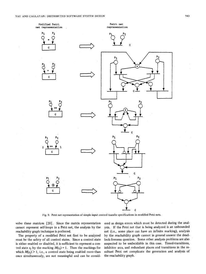
Petri net representations of components with different inputand output control transfer specifications are shown in Figs. 9and 10, respectively. When a component is transformed intoits Petri net representation, some number of redundant Petrinet places and transitions may be generated. In addition, someof the transitions are timed-transitions [30], and inhibitor arcsmay also exist in the equivalent Petri net representation.There are two basic techniques for the analysis of Petri nets.
One is the analysis using the reachability graph (also called areachability tree), and the other is the analysis by linear alge-bra. Advantages and disadvantages of both techniques withrespect to their capabilities to solve the Petri net problems arereviewed in [20]. The reachability graph is a finite, compactrepresentation of the reachability set and the transition firingsof a Petri net. The reachability set is the set of all markingsthat are reachable from an initial marking. A marking ml isreachable from a marking m2 if ml can be obtained from m2by firing a flnite number of transitions. An algorithm to con-struct the reachability graph of a Petri net is given in [20].The linear algebraic techniques use two matrices to representa Petri net graph and a vector for the initial marking. Then,the net can be analyzed by solving matrix equations that in-
742
-- - -IIIII
.--*LBtTFJ--- -L.x.
IIII
L.,
YAU AND CAGLAYAN: DISTRIBUTED SOFTWARE SYSTEM DESIGN
Iiodified Petrinet representation
P1 P2
rn
P1 P2
p1 P2
PI P2
2 I
P1 P2O
s j
Petri* netrepresentation
P1 P2
r ~CE
P1 p2
Fig. 9. Petri net representation of simple input control transfer specifications in modified Petri nets.
volve these matrices [20]. Since the matrix representationcannot represent self-loops in a Petri net, the analysis by thereachability graph technique is preferred.The property of a modified Petri net first to be analyzed
must-be the safety of all control states. Since a control stateis either enabled or disabled, it is sufficient to represent a con-trol state si by the marking M(si) = 1. Then the markings forwhich M(s1) > 1, i.e., a control state being enabled more thanonce simultaneously, are not meaningful and can be consid-
ered as design errors which must be detected during the anal-ysis. If the Petri net that is being analyzed is an unboundednet (i.e., some place can have an infinite marking), analysisby the reachability graphs cannot in general answer the dead-lock-freeness question. Some other analysis problems are alsosuspected to be undecidable in this case. Timed-transitions,inhibitor arcs, and redundant places and transitions in the re-
sultant Petri net complicate the generation and analysis ofthe reachability graph.
743

IEEE TRANSACTIONS ON SOFTWARE ENGINEERING, VOL. SE-9, NO. 6, NOVEMBER 1983
Petri netrepresentation
C
C
F 4,
C
q1
C-
ql q2
Fig. 10. Petri net representation of simple output control transferspecifications in modified Petri nets.
Currently we are developing some tools for performing thetransformation of the design representations into Petri netsand for analyzing these resulting Petri nets. Using this tech-nique, we are limited to performing control flow analysis ofthe type described previously. Thus, direct analysis of themodified Petri nets both from control and data flow points ofview is also being studied.
V. DISCUSSION
A model for representing and analyzing the design of a dis-tributed software system has been presented. The model isbased on a modified form of Petri nets and enables one torepresent both the structure and the behavior of a distributedsoftware system. A representation in the form of a modifiedPetri net can be transformed into an ordinary Petri net whichcan be analyzed in order to verify certain behavioral properties.
Several modifications to ordinary Petri nets have been carriedout in order to obtain the modified Petri net model. Petri netplaces, which are renamed as control state variables, are exclu-sively used to describe the control information in a designrepresentation. Transitions are treated as executable units of
software and are called software components. The simpletransition firing rule of Petri nets is generalized to input andoutput control transfer specifications. Modifications to thetransition firing rule are sufficiently general so that both a largenumber of conditions under which a software component can
start to be executed and the mechanism by which a softwarecomponent interacts with its control environment can bespecified in a compact form. Data objects which are connectedto software components by directed arcs, and data typeswhich are also connected to software components are addedto a Petri net so that data aspects of a design representationcan be described. A data transfer specification is associatedwith a software component to describe how a componentmodifies its data environment.For the purpose of design analysis, structural and behavioral
properties of a design representation given in the form of a
modified Petri net are identified. The modifled Petri net isfirst transformed into an equivalent ordinary Petri net, thenthat resulting Petri net is analysed in order to verify behavioralproperties such as safeness, deadlock-freeness, mutual exclu-sion, and proper termination. Although certain analysis prob-lems for Petri nets are known to be undecidable, the limitationof boundedness enforced through the transformation process
results in the removal of any undecidable problems. Still, theexponential complexity of boundedness and liveness problemsmakes the analysis quite difficult.More work needs to be done to determine whether the input
and output control transfer specifications in their current formcan completely specify all possible forms of the execution ofcomponents and all possible forms of output control state setmodifications. For large-scale distributed software systems,some design experimentation is necessary to determine thetype and amount of detail a final design level must include forthe purpose of separating the design and programming issues.The modified Petri nets are currently unable to represent theperformance and reliability constraints as part of the designrepresentation. Also, the software is assumed to have a staticstructure. Therefore, there is a need to extend modified Petrinets so that additional constraints and the dynamic structure ofdistributed software systems can be represented during thedesign process. Such an extension of the representation tech-nique will require the development of extensive analysis tech-niques for validating the performance and reliability constraints.Finally, the representation technique must be integrated intoan overall design methodology. The methodology must addressthe critical issue of system partitioning and it must be com-
patible with the representation scheme.
ACKNOWLEDGMENT
The authors would like to express their thanks to S. Shatzof Northwestern University for many helpful discussions.
REFERENCES[ 1] D. L. Parnas, "On the criteria to be used in decomposing systems
into modules," Commun. Ass. Comput. Mach., voL 15, no. 12,pp. 1053-1058, 1972.
[2] 0. J. Dahi E. W. Dijkstra, and C. A. R. Hoare, Structured Pro-gramming. New York: Academic, 1972.
Modified Petrinet representation
744

YAU AND CAGLAYAN: DISTRIBUTED SOFTWARE SYSTEM DESIGN
[3] W. P. Stevens, G. F. Myers, and L. C. Constantine, "Structureddesign," IBM Syst. J., voL 13, no. 2, pp. 115-139, 1974.
[4] E. Yourdon and L. L. Constantin, Structured Design. NewYork: Yourdon, Inc., 1975.
[5] M. A. Jackson, Principles of Program Design. London: Aca-demic, 1975.
[6] P. Brinch-Hansen, "Distributed processes: A concurrent program-ming concept," Commun. Ass. Comput. Mach., voL 21, no. 11,pp. 934-941, Nov. 1978.
[7] C. A. R. Hoare, "Communicating sequential processes," Commun.Ass. Comput. Mach., voL 21, no. 8, pp. 666-677, Aug. 1978.
[8] - "Monitors: An operating system structuring concept," Com-mun. Ass. Comput. Mach., voL 17, no. 10, pp. 549-557, Oct.1974.
[9] 0. J. DahL B. Myhrhaug, and K. Nygaard, Simula 67-CommonBase Language. Oslo: Norwegian Comput. Cen., May 1968.
[10] C. Hewitt and R. Atkinson, "Parallelism and synchronization inactor systems," in Proc. 4th ACM Symp. Principles of Program-ming Languages, Jan. 1977, pp. 267-280.
[11] R. Milner, A Calculus of Communicating Systems (Lecture Notesin Comput. Sci), voL 92. New York: Springer-Verlag, 1980.
[12] G. Kahn, "The semantics of a simple language for parallel pro-gramming," in Proc. IFIP Congr. 74, Aug. 1974, pp. 471-475.
[13] D. B. MacQueen, "Models for distributed computing," IRIATech. Rep. 351, Apr. 1979.
[14] C. A. Petri "Kommunikation mit Automaten " Ph.D. disserta-tion (in German); trans. by C. F. Greene, Suppi 1 to RADC-TR-65-337, voL 1, Rome Air Develop. Cen., Griffiss AFB, NY, 1965.
[15] A. W. Holt et at, "Final report of the information system theoryproject," RADC-TR-68-305, Rome Air Develop. Cen., GriffissAFB, NY, Sept. 1968.
[16] A. W. Holt, and F. Commoner, "Evenits and conditions," inRec.Project MAC Conf. on Concurrent Syst. and Parallel Comput.,1970, pp. 3-52.
[17] J. B. Dennis, "Modular asynchronous control structures for ahigh performance processor," in Rec. Project MAC Conf on Con-current Syst. and Parallel Comput., 1970, pp. 55-80.
[18] W. Brauer, Net Theory and Applications (Lecture Notes in Com-put. Sci), voL 84. New York: Springer-Verlag, 1980.
[19] J. L. Peterson, "Petri nets," ACM Comput. Surveys, voL 9, pp.223-252, Sept. 1977.
[20] -, Petri Net Theory and the Modeling of Systems. EnglewoodCliffs, NJ: Prentice-HalL 1981.
[21] S. S. Yau, C. C. Yang, and S. M. Shatz, "An approach to distrib-uted computing system software design," IEEE Trans. SoftwareEng., voL SE-7, pp. 427-436, July 1981.
[22] L. J. Mekly, and S. S. Yau, "Software design representation usingabstract process networks," IEEE Trans. Software Eng., vol. SE-6, pp. 420-435, Sept. 1980.
[23] P. M. Lu, and S. S. Yau, "A methodoiogy for representing theformal specification of distributed computing system softwaredesign," in Proc. 1st Int. Conf Distributed Comput. Syst., Oct.1979, pp. 212-221.
[24] S. S. Yau, and S. M. Shatz, "On communication in the design ofsoftware components of distributed computer systems," in Proc.3rd Int. Conf Distributed Comput. Syst., Oct. 1982, pp. 280-287.
[25] I. M. Campos, and G. Estrin, "Concurrent software system de-sign," in Proc. 3rdlnt. Conf. Software Eng., May 1978, pp. 230-242.
[26] P. E. Lauer, P. R. Torrigiani, and M. W. Shields, "COSY-A sys-tem specification language based on paths and processes," ActaInformatica, voL 12, pp. 109-158, 1979.
[27] P. E. Lauer, M. W. Shields, and E. Best, "Design and analysis ofhighiy parallel and distributed systems," in Abstract SoftwareSpecifications (Lecture Notes in Comput. Sci), voL 86, D.Bjorner, Ed. New York: Springer-Verlag, 1980, pp. 451-503.
[28] T. Agerwala, "An analysis of controlLng agents for asynchronousprocesses," Dep. Comput. Sci., Johns Hopkins Univ., Rep. TR-35, Aug. 1974.
[29] S. S. Patil "Coordination of asynchronous events," Ph.D. disser-tation, TR-72, Project MAC, MIT, Rep. TR-72, June 1970.
[30] C. Ramchandani, "Analysis of asynchronous sytems by Petrinets," PIhD. dissertation, Project MAC, MIT, Rep. TR-120,1973.
[31] F. Commoner et al., "Marked directed graphs," J. Comput. Syst.Sci, voL 5, pp. 511-523, Oct. 1971.
[32] G. J. Nutt, "Evaluation nets for computer system performanceanalysis," in Proc. 1972 Fall Joint Comput. Conf., voL 41, pp.279-236.
[33] J. D. Noe, and G. J. Nutt, "Macro E-nets for representation ofparallel systems," IEEE Trans Comput., voL C-22, pp. 718-727,Aug. 1973.
[34] J. D. Noe, "Hierarchical modeling with pro-nets," in Proc. Nat.Electron. Conf., voL 32, Oct. 1978, pp. 155-160.
[351 W. Trattnig and H. Kerner, "EDDA-A very high-level program-ming and specification language in the style of SADT," in Proc.Compsac 80, Oct. 1980, pp. 436-443.
[36] R. Valette, and M. Diaz, "Top-down formal specification andverification of paraDel control systems," Digital Processes, voL 4,pp. 181-199, 1978.
[37] C. A. Petri "Interpretations of net theory," GMD-ISF Rep. 75-07, July 1975.
[38] J. V. Guttag and J. J. Horning, "The algebraic specification ofabstract data types," Acta Informatica, vol 10, pp. 27-52, 1978.
[39] J. Guttag, "Notes on type abstraction (version 2)," IEEE Trans.Software Eng., voL SE-6, pp. 13-24, Jan. 1980.
[40] E. W. Dijkstra, "Guarded commands, nondeterminacy and formalderivation of programs," Commun Ass. Comput. Mach., voL 18,pp. 453-457, Aug. 1978.
Stephen S. Yau (S'60-M'61-SM'68-F'73) re-
ceived the B.S. degree from the National Tai-wan University, Taipei, Taiwan, China, in 1958,and the M.S. and Ph.D. degrees from the Univer-sity of Illinois, Urbana, in 1959 and 1961, re-spectively, all in electrical engineering.He joined the faculty of the Department of
Electrical Engineering, Northwestern University,Evanston, IL, in 1961, and is now Professor andChairman of the Department of Electrical Engi-neering and Computer Science. He is currently
interested in reliability and maintainability of computing systems, soft-ware engineering, and distributed computer systems. He has publishednumerous technical papers in these and other areas.Dr. Yau is a Fellow of the Franklin Institute from which he received
the Louis E. Levy Medal in 1963; he is also a Fellow of the AmericanAssociation for the Advancement of Science. He received the GoldenPlate Award of the American Academy of Achievement in 1964, andthe first Richard E. Merwin Award of IEEE Computer Society in 1981.He was the President of the IEEE Computer Society in 1974-1975, theDivision V (Computer Society) Director of the IEEE in 1976-1977,and the Chairman of the IEEE Technical Activities Board DevelopmentCommittees in 1979. He has been a Director of the American Federa-tion of Information Processing Societies (AFIPS) from 1972 to 1982and is now the Vice President of AFIPS. He is also now the Editor-in-Chief of IEEE COMPUTER magazine. He was the Conference Chair-man of the First Annual IEEE Computer Conference, Chicago, 1967,and the General Chairman of the 1974 National Computer Conference,Chicago; the General Chairman of the IEEE Computer Society's FirstInternational Computer Software and Applications Conference, Chi-cago, 1977 (COMPSAC '77), and the Chairman of National ComputerConference Board in 1982-1983. He is also a member of Associationfor Computing Machinery, Society for Industrial and Applied Mathe-matics, American Society for Engineering Education, Sigma Xi TauBeta Pi and Eta Kappa Nu.
Mehmet U. Caglayan (S'76-M'82) was born in Ankara, Turkey, on July21, 1951. He received the B.S. degree in electrical engineering and theM.S. degree in computer science from the Middle East Technical Uni-versity, Ankara, Turkey, in 1973 and 1975, respectively, and the Ph.D.degree in computer science from Northwestern University, Evanston,IL, 1982.He is now an Assistant Professor at the University of Petroleum and
Minerals, Dhahran, Saudi Arabia.Dr. Caglayan is a member of Turkish Society of Electrical Engineers
and the Association for Computing Machinery.
745