distributed systems cs 15-440 virtualization- part ii lecture 24, dec 7, 2011 majd f. sakr, mohammad...
Post on 19-Dec-2015
216 views
TRANSCRIPT
Distributed SystemsCS 15-440
Virtualization- Part II
Lecture 24, Dec 7, 2011
Majd F. Sakr, Mohammad Hammoud andVinay Kolar
1
Today…
Last session Virtualization- Part I
Today’s session Virtualization – Part II
Announcements: PS4 is due today by 11:59PM Project 4 is due on Dec 13 by 11:59PM (No deadline extension) On Monday Dec 12, each team will present its work on project 4
2
Objectives
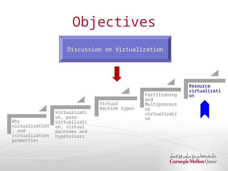
Discussion on Virtualization
Virtual machine types
Partitioning and Multiprocessor virtualization
Resource virtualization
Why virtualization, and virtualization properties
Virtualization, para-virtualization, virtual machines and hypervisors
Resource virtualization
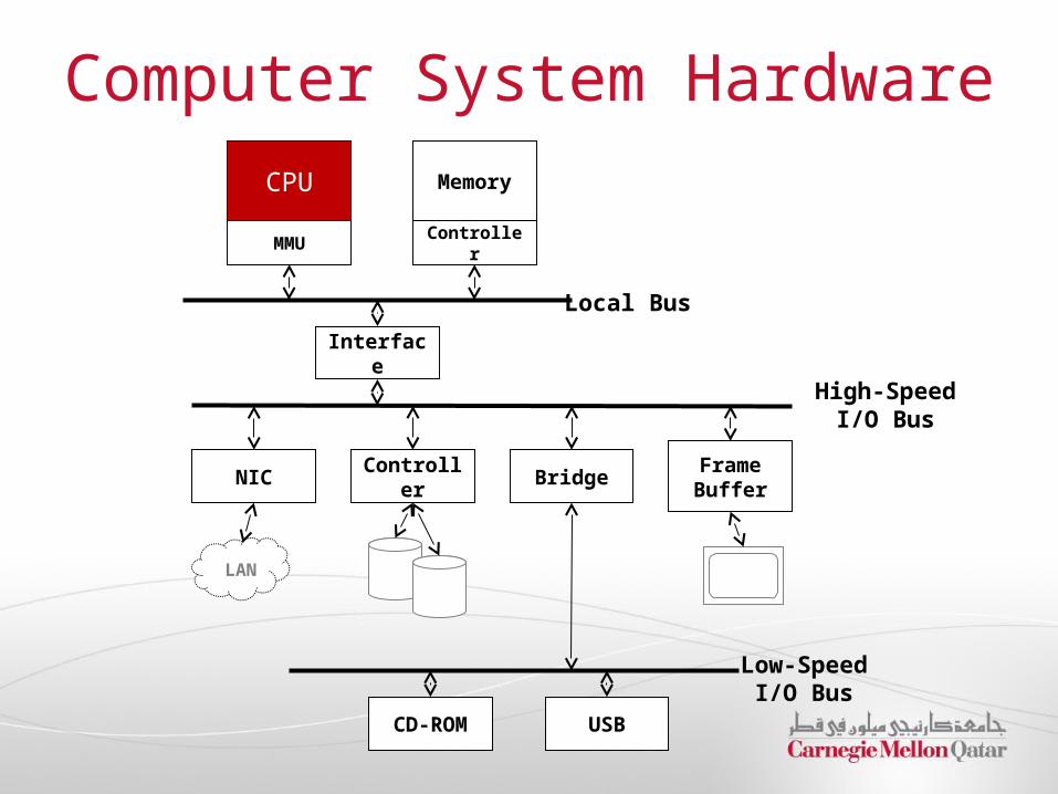
Computer System Hardware
CPU
MMU
Memory
Controller
Local Bus
Interface
High-SpeedI/O Bus
NIC Controller BridgeFrame Buffer
LAN
Low-SpeedI/O Bus
USBCD-ROM
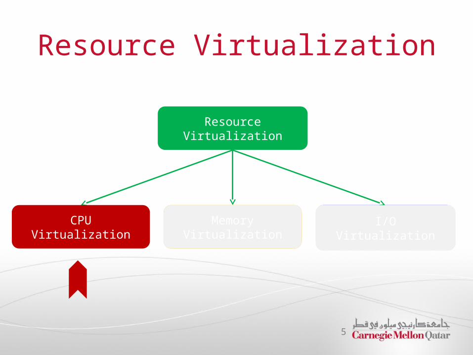
Resource Virtualization
5
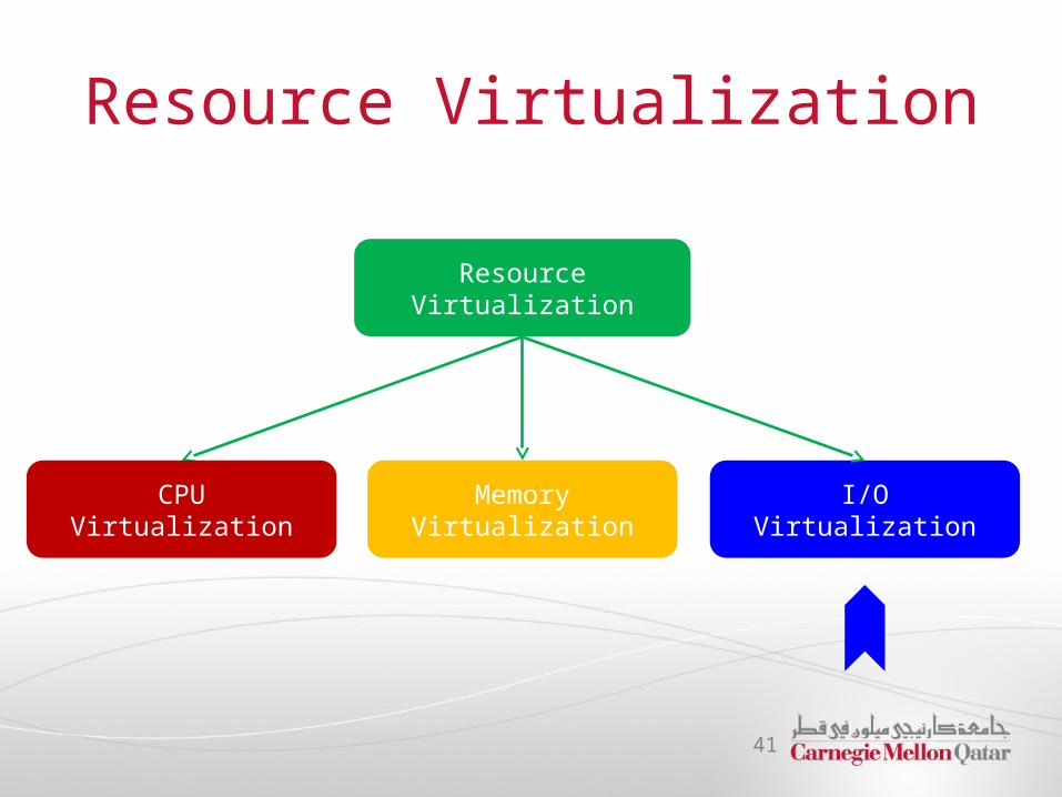
Resource Virtualization
CPU Virtualization I/O VirtualizationI/O VirtualizationMemory VirtualizationMemory Virtualization
CPU Virtualization
Interpretation and Binary Translation Virtualizable ISAs
CPU Virtualization
Interpretation and Binary Translation Virtualizable ISAs
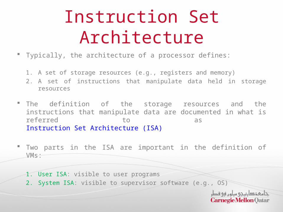
Instruction Set Architecture
Typically, the architecture of a processor defines:
1. A set of storage resources (e.g., registers and memory)
2. A set of instructions that manipulate data held in storage resources
The definition of the storage resources and the instructions that manipulate data are documented in what is referred to as Instruction Set Architecture (ISA)
Two parts in the ISA are important in the definition of VMs:
1. User ISA: visible to user programs
2. System ISA: visible to supervisor software (e.g., OS)
Ways to Virtualize CPUs
The key to virtualize a CPU lies in the execution of the guest instructions, including both system-level and user-level instructions
Virtualizing a CPU can be achieved in one of two ways:
1. Emulation: the only processor virtualization mechanism available when the ISA of the guest is different from the ISA of the host
2. Direct native execution: possible only if the ISA of the host is identical to the ISA of the guest
Emulation
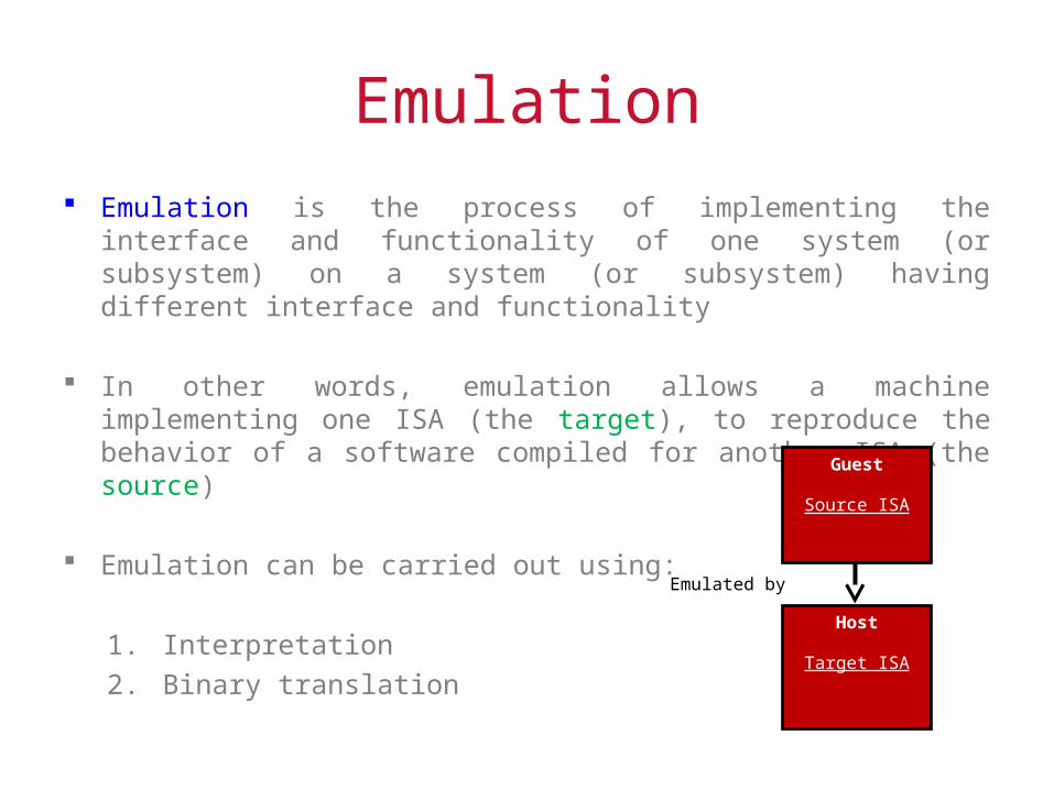
Emulation is the process of implementing the interface and functionality of one system (or subsystem) on a system (or subsystem) having different interface and functionality
In other words, emulation allows a machine implementing one ISA (the target), to reproduce the behavior of a software compiled for another ISA (the source)
Emulation can be carried out using:
1. Interpretation
2. Binary translation
Guest
Source ISA
Host
Target ISA
Emulated by
Basic Interpretation
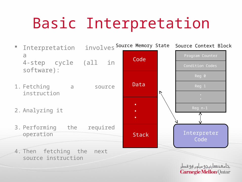
Interpretation involves a 4-step cycle (all in software):
1. Fetching a source instruction
2. Analyzing it
3. Performing the required operation
4. Then fetching the next source instruction
Code
Data
• • •
Stack
Program Counter
Condition Codes
Reg 0
Reg 1
• •
Reg n-1
Interpreter Code
Source Memory State Source Context Block
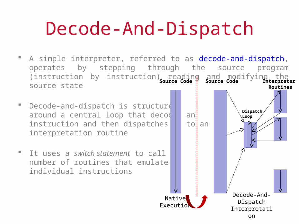
Decode-And-Dispatch A simple interpreter, referred to as decode-and-dispatch, operates by stepping
through the source program (instruction by instruction) reading and modifying the source state
Decode-and-dispatch is structured around a central loop that decodes an instruction and then dispatches it to an interpretation routine
It uses a switch statement to call a number of routines that emulate individual instructions
Source Code
DispatchLoop
Source Code Interpreter Routines
Native Execution
Decode-And-Dispatch
Interpretation
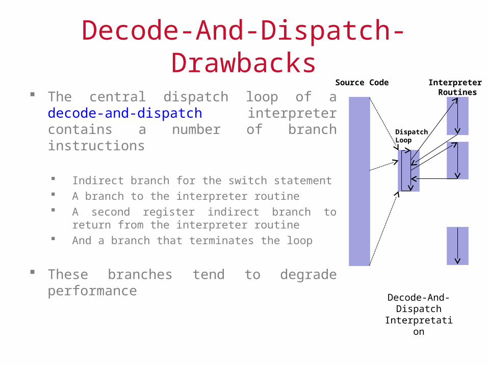
Decode-And-Dispatch- Drawbacks
The central dispatch loop of a decode-and-dispatch interpreter contains a number of branch instructions
Indirect branch for the switch statement A branch to the interpreter routine A second register indirect branch to return from the
interpreter routine And a branch that terminates the loop
These branches tend to degrade performance
DispatchLoop
Source Code Interpreter Routines
Decode-And-Dispatch
Interpretation
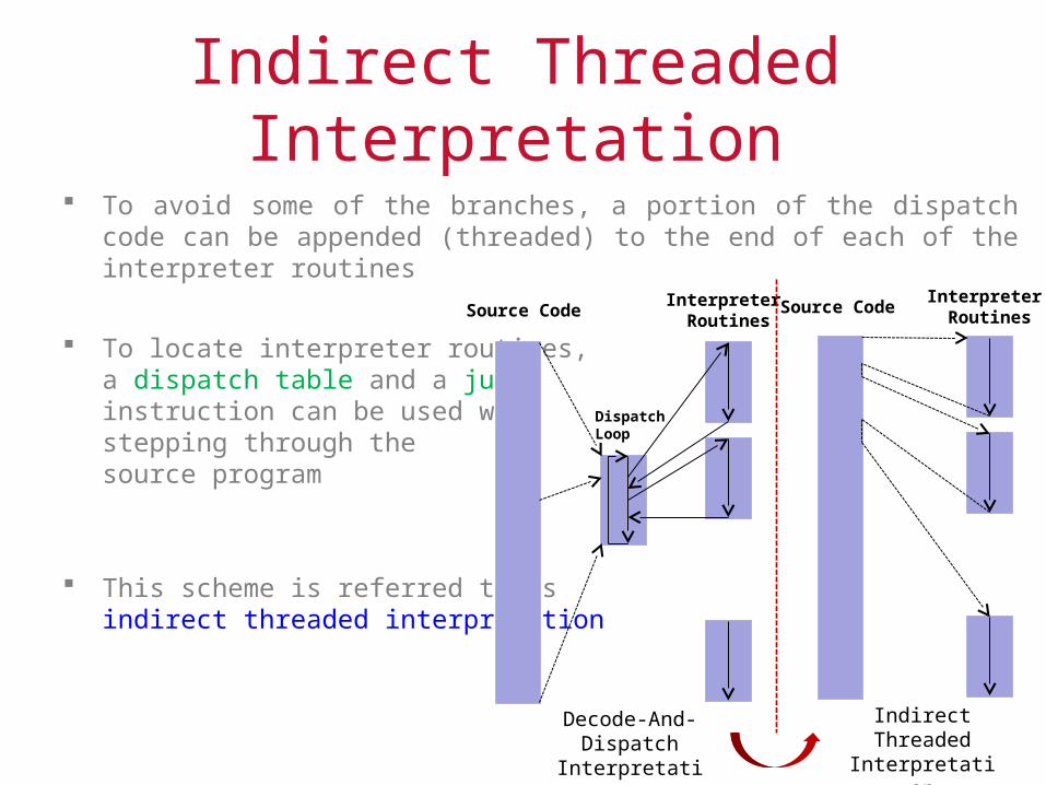
Indirect Threaded Interpretation To avoid some of the branches, a portion of the dispatch code can be
appended (threaded) to the end of each of the interpreter routines
To locate interpreter routines, a dispatch table and a jump instruction can be used when stepping through the source program
This scheme is referred to as indirect threaded interpretation
Source CodeInterpreter Routines
DispatchLoop
Source CodeInterpreter Routines
Decode-And-Dispatch
Interpretation
Indirect Threaded
Interpretation
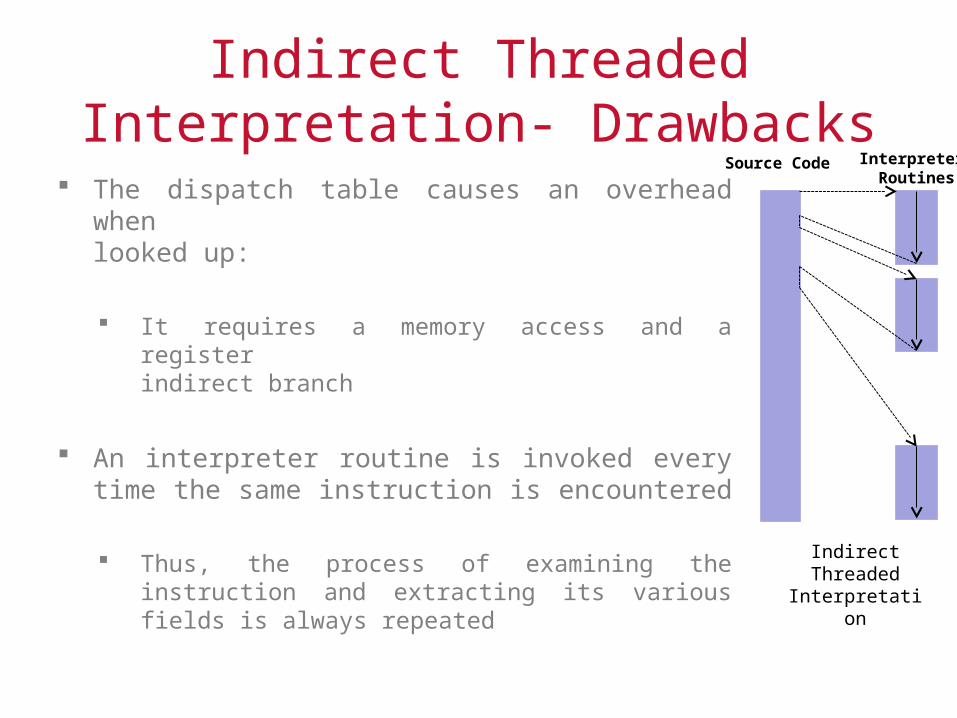
Indirect Threaded Interpretation- Drawbacks
The dispatch table causes an overhead when looked up:
It requires a memory access and a register indirect branch
An interpreter routine is invoked every time the same instruction is encountered
Thus, the process of examining the instruction and extracting its various fields is always repeated
Source Code Interpreter Routines
Indirect Threaded
Interpretation
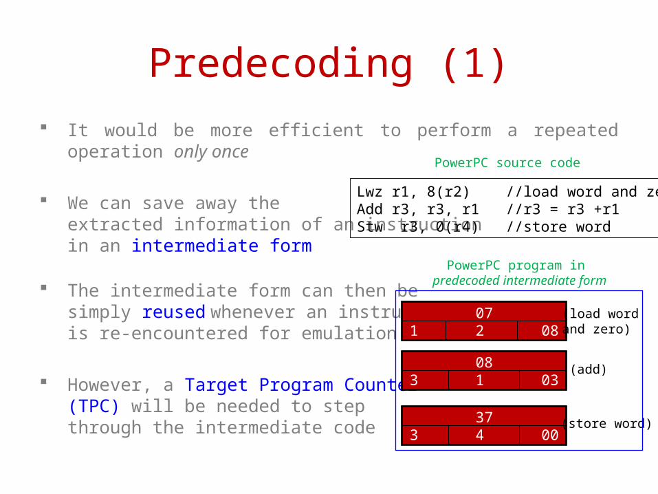
Predecoding (1)
It would be more efficient to perform a repeated operation only once
We can save away the extracted information of an instruction in an intermediate form
The intermediate form can then be simply reused whenever an instruction is re-encountered for emulation
However, a Target Program Counter (TPC) will be needed to stepthrough the intermediate code
Lwz r1, 8(r2) //load word and zeroAdd r3, r3, r1 //r3 = r3 +r1Stw r3, 0(r4) //store word
PowerPC source code
071 2 08
083 1 03
373 4 00
(load word and zero)
(add)
(store word)
PowerPC program in predecoded intermediate form
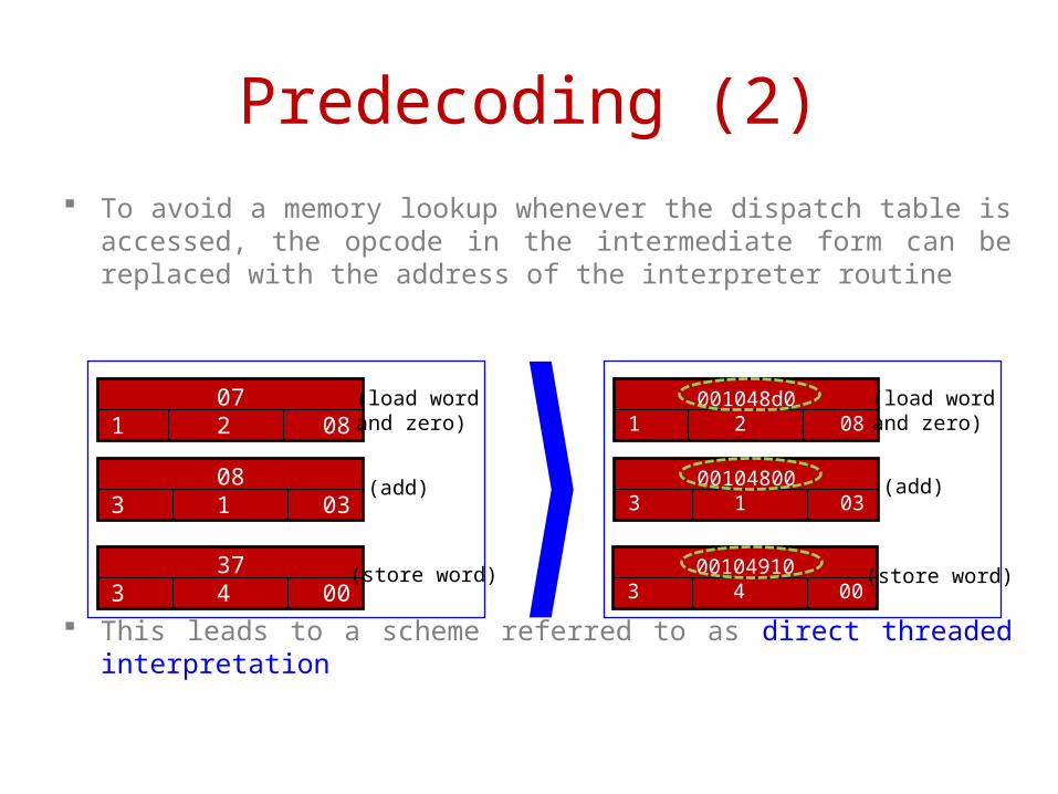
Predecoding (2)
To avoid a memory lookup whenever the dispatch table is accessed, the opcode in the intermediate form can be replaced with the address of the interpreter routine
This leads to a scheme referred to as direct threaded interpretation
001048d01 2 08
001048003 1 03
001049103 4 00
(load word and zero)
(add)
(store word)
071 2 08
083 1 03
373 4 00
(load word and zero)
(add)
(store word)
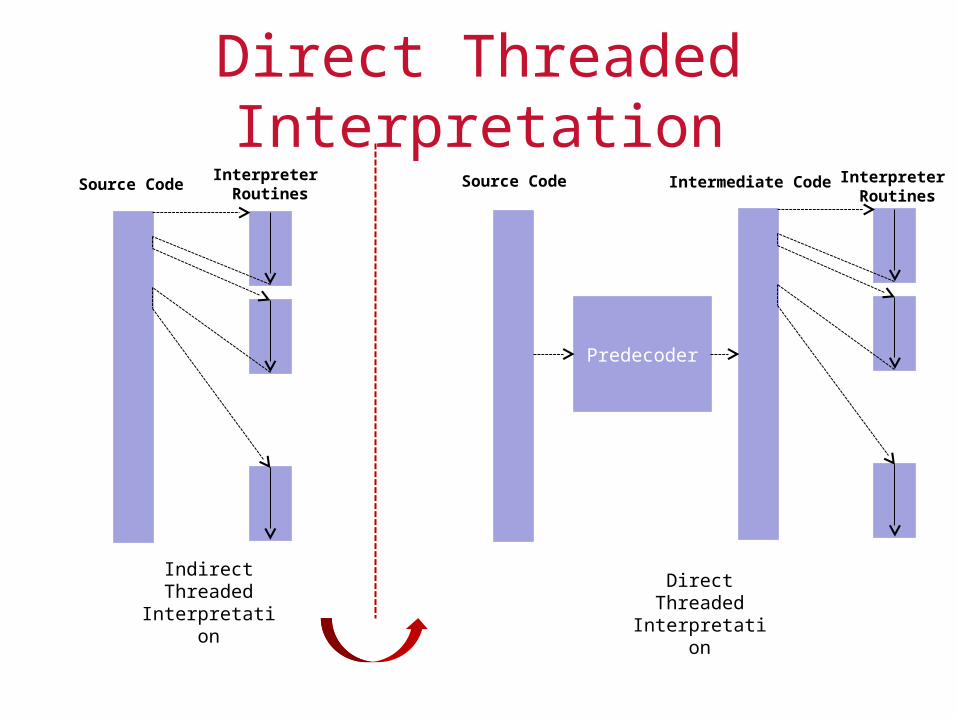
Direct Threaded InterpretationSource Code Interpreter
Routines
Predecoder
Intermediate CodeSource CodeInterpreter Routines
Indirect Threaded
Interpretation
Direct Threaded Interpretation
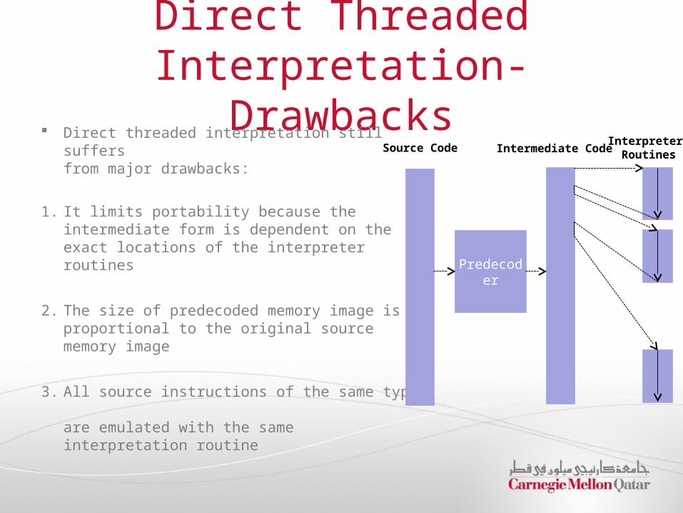
Direct Threaded Interpretation- Drawbacks
Direct threaded interpretation still suffers from major drawbacks:
1. It limits portability because the intermediate form is dependent on the exact locations of the interpreter routines
2. The size of predecoded memory image is proportional to the original source memory image
3. All source instructions of the same type are emulated with the same interpretation routine
Source CodeInterpreter Routines
Predecoder
Intermediate Code
Binary Translation
Performance can be significantly enhanced by mapping each individual source binary instruction to its own customized target code
This process of converting the source binary program into a target binary program is referred to as binary translation
Binary translation attempts to amortize the fetch and analysis costs by:
1. Translating a block of source instructions to a block of target instructions
2. Caching the translated code for repeated use
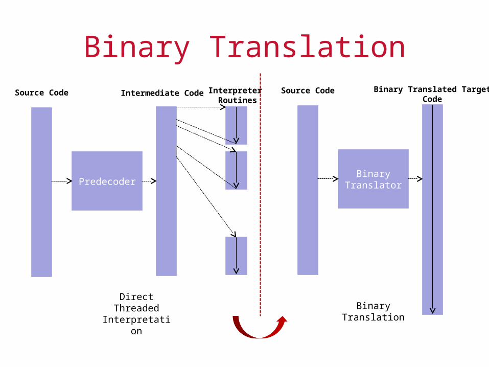
Binary TranslationSource Code
Binary Translator
Binary Translated TargetCode
Source Code Interpreter Routines
Predecoder
Intermediate Code
Direct Threaded Interpretation Binary
Translation
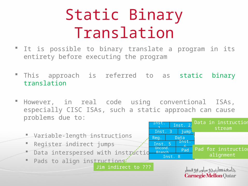
Static Binary Translation
It is possible to binary translate a program in its entirety before executing the program
This approach is referred to as static binary translation
However, in real code using conventional ISAs, especially CISC ISAs, such a static approach can cause problems due to:
Variable-length instructions Register indirect jumps Data interspersed with instructions Pads to align instructions
Inst. 1 Inst. 2
Inst. 3 jump
Reg. Data
Inst. 5 Inst. 6
Uncond. Branch Pad
Inst. 8
Data in instruction stream
Pad for instructionalignment
Jim indirect to ???
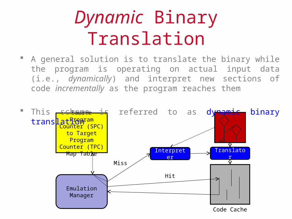
Dynamic Binary Translation
Source Program Counter (SPC) to Target Program Counter (TPC)
Map Table
Emulation Manager
Interpreter Translator
Miss
Hit
Code Cache
A general solution is to translate the binary while the program is operating on actual input data (i.e., dynamically) and interpret new sections of code incrementally as the program reaches them
This scheme is referred to as dynamic binary translation
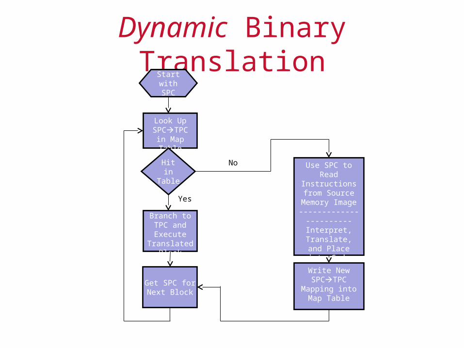
Dynamic Binary TranslationStart with SPC
Look Up SPCTPC
in Map Table
Hit in Table
Use SPC to Read Instructions
from Source Memory Image
-----------------------Interpret,
Translate, and Place into Code
Cache
Write New SPCTPC
Mapping into Map Table
Branch to TPC and Execute Translated
Block
Get SPC for Next Block
No
Yes
CPU Virtualization
Interpretation and Binary Translation Virtualizable ISAs
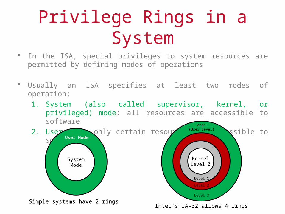
Privilege Rings in a System In the ISA, special privileges to system resources are permitted by defining
modes of operations
Usually an ISA specifies at least two modes of operation:
1. System (also called supervisor, kernel, or privileged) mode: all resources are accessible to software
2. User mode: only certain resources are accessible to software
System Mode
User Mode
KernelLevel 0
Level 1
Level 2
Level 3
Apps(User Level)
Simple systems have 2 ringsIntel’s IA-32 allows 4 rings
Conditions for ISA Virtualizability In a native system VM, the VMM runs in system mode, and all other
software run in user mode
A privileged instruction is defined as one that traps if the machine is in user mode and does not trap if the machine is in system mode
Examples of Privileged Instructions are:
Load PSW: If it can be accessed in user mode, a malicious user program can put itself in system mode and get control of the system
Set CPU Timer: If it can be accessed in user mode, a malicious user program can change the amount of time allocated to it before getting context switched
Types of Instructions Instructions that interact with hardware can be classified into
three categories:
1. Control-sensitive: Instructions that attempt to change the configuration of resources in the system (e.g., memory assigned to a program)
2. Behavior-sensitive: Instructions whose behaviors or results depend on the configuration of resources
3. Innocuous: Instructions that are neither control-sensitive nor behavior-sensitive
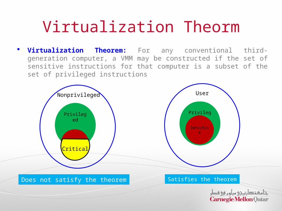
Virtualization Theorm Virtualization Theorem: For any conventional third-generation computer, a
VMM may be constructed if the set of sensitive instructions for that computer is a subset of the set of privileged instructions
Privileged
Sensitive
Nonprivileged
Privileged
Sensitive
User
Does not satisfy the theorem Satisfies the theorem
Critical
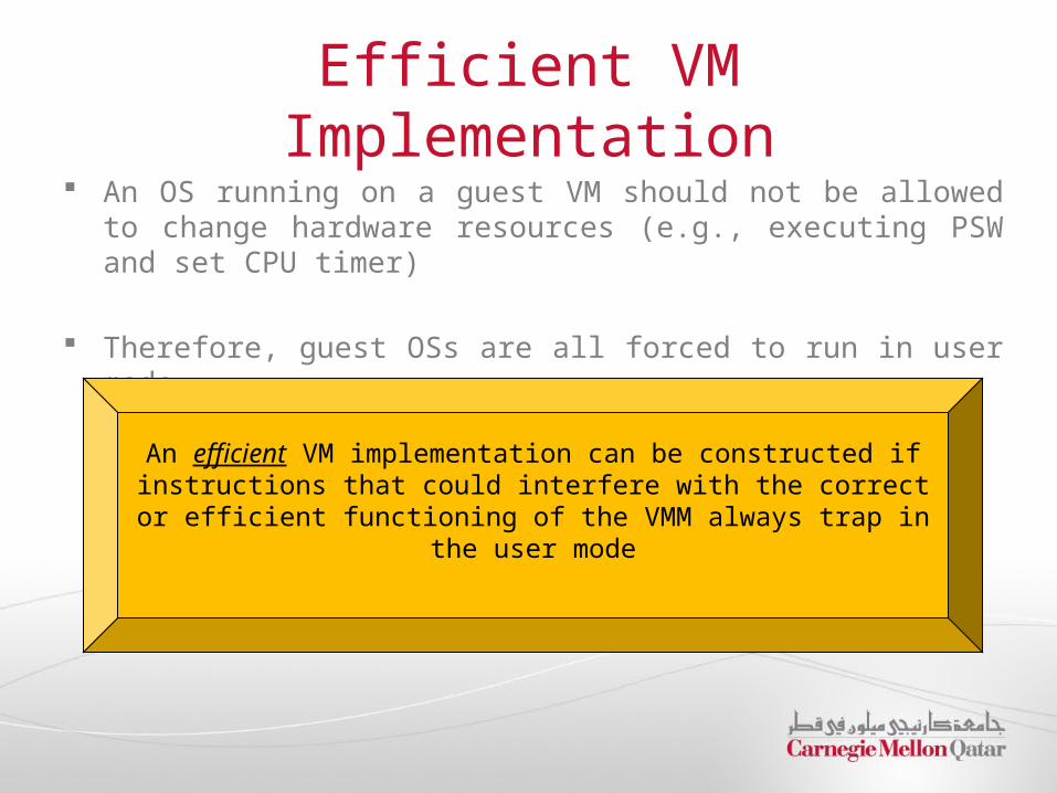
Efficient VM Implementation An OS running on a guest VM should not be allowed to change
hardware resources (e.g., executing PSW and set CPU timer)
Therefore, guest OSs are all forced to run in user mode
An efficient VM implementation can be constructed if instructions that could interfere with the correct or efficient functioning of the VMM
always trap in the user mode
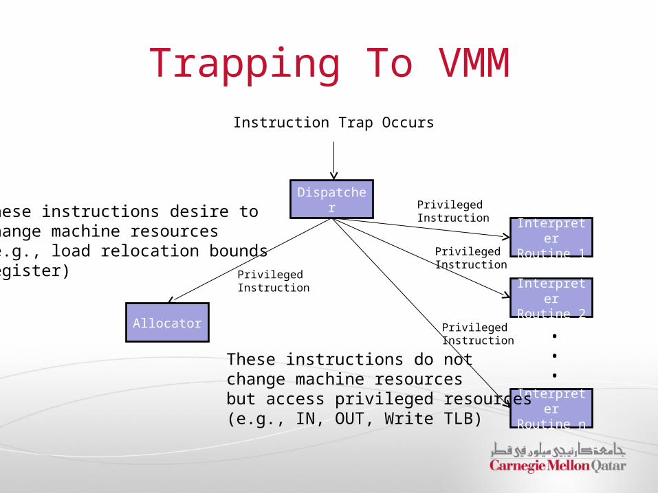
Trapping To VMM
Dispatcher
Interpreter Routine 1
Interpreter Routine 2
• • •
Interpreter Routine n
Allocator
Instruction Trap Occurs
PrivilegedInstruction
PrivilegedInstruction
PrivilegedInstruction
PrivilegedInstruction
These instructions do notchange machine resources but access privileged resources(e.g., IN, OUT, Write TLB)
These instructions desire tochange machine resources (e.g., load relocation bounds register)
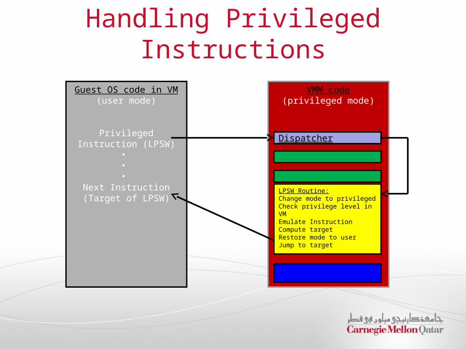
Handling Privileged Instructions
Guest OS code in VM(user mode)
Privileged Instruction (LPSW)
• • •
Next Instruction (Target of LPSW)
VMM code(privileged mode)
Dispatcher
LPSW Routine:Change mode to privileged Check privilege level in VMEmulate InstructionCompute targetRestore mode to userJump to target
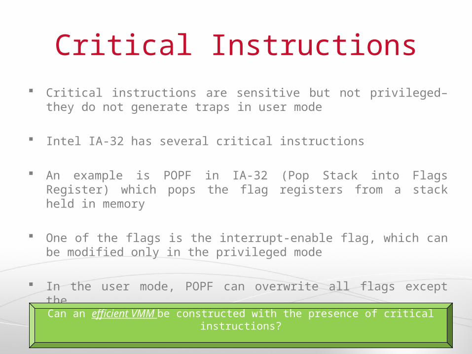
Critical Instructions Critical instructions are sensitive but not privileged– they do not generate
traps in user mode
Intel IA-32 has several critical instructions
An example is POPF in IA-32 (Pop Stack into Flags Register) which pops the flag registers from a stack held in memory
One of the flags is the interrupt-enable flag, which can be modified only in the privileged mode
In the user mode, POPF can overwrite all flags except the interrupt-enable flag (for this it acts as no-op)
Can an efficient VMM be constructed with the presence of critical instructions?
Handling Critical Instructions
Critical Instructions are problematic and they inhibit the creation of an efficient VMM
However, if an ISA is not efficiently virtualizable, this does not mean we cannot create a VMM
The VMM can scan the guest code before execution, discover all critical instructions, and replace them with traps (system calls) to the VMM
This replacement process is known as patching
Even if an ISA contains only ONE critical instruction, patching will be required
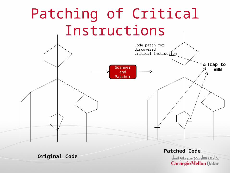
Patching of Critical Instructions
Scanner and Patcher
Trap to VMM
Code patch for discovered critical instruction
Original CodePatched Code
Code Caching
Some of the critical instructions that trap to the VMM might require interpretation
Interpretation overhead might slow down the VMM especially if the frequency of critical instructions requiring interpretations increases
To reduce overhead, interpreted instructions can be cached, using a strategy known as code caching
Code caching is done on a block of instructions surrounding the critical instruction (larger blocks lend themselves better to optimization)
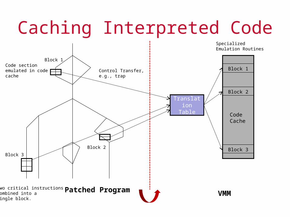
Caching Interpreted Code
Control Transfer,e.g., trap
VMM
Specialized Emulation Routines
Patched Program
Block 1Code section emulated in codecache
Block 3
Two critical instructions combined into a single block.
Block 1
Block 2
Block 3
Code Cache
Translation Table
Block 2
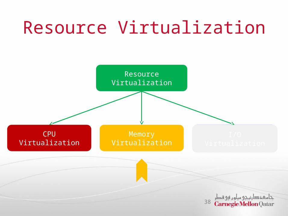
Resource Virtualization
38
Resource Virtualization
CPU Virtualization I/O VirtualizationI/O VirtualizationMemory Virtualization
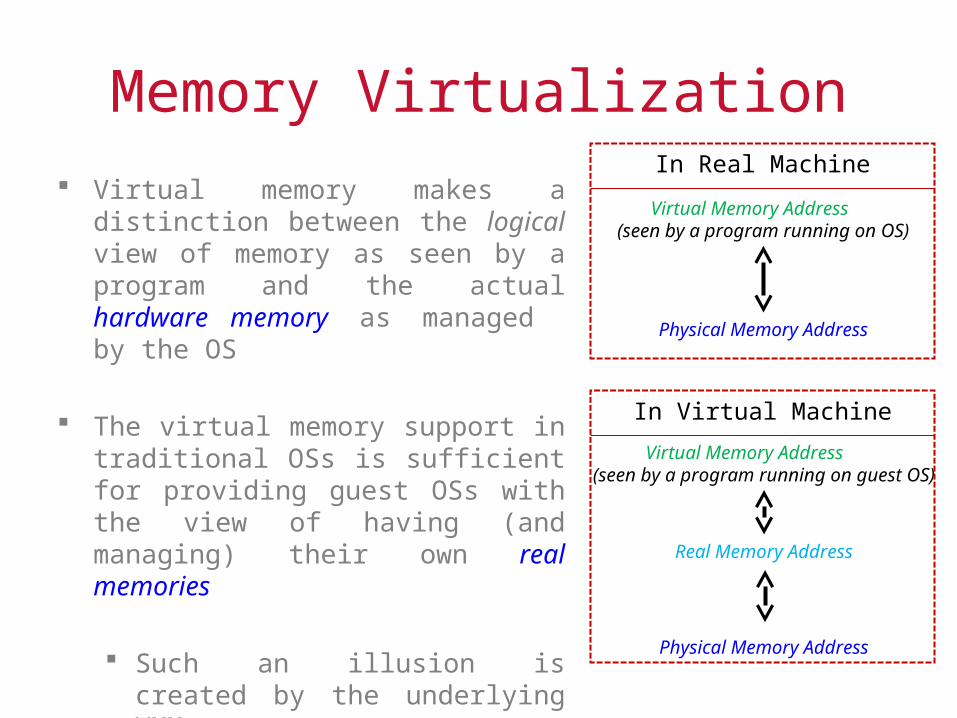
Memory Virtualization
Virtual memory makes a distinction between the logical view of memory as seen by a program and the actual hardware memory as managed by the OS
The virtual memory support in traditional OSs is sufficient for providing guest OSs with the view of having (and managing) their own real memories
Such an illusion is created by the underlying VMM
Virtual Memory Address (seen by a program running on OS)
Physical Memory Address
In Real Machine
Virtual Memory Address(seen by a program running on guest OS)
Real Memory Address
In Virtual Machine
Physical Memory Address
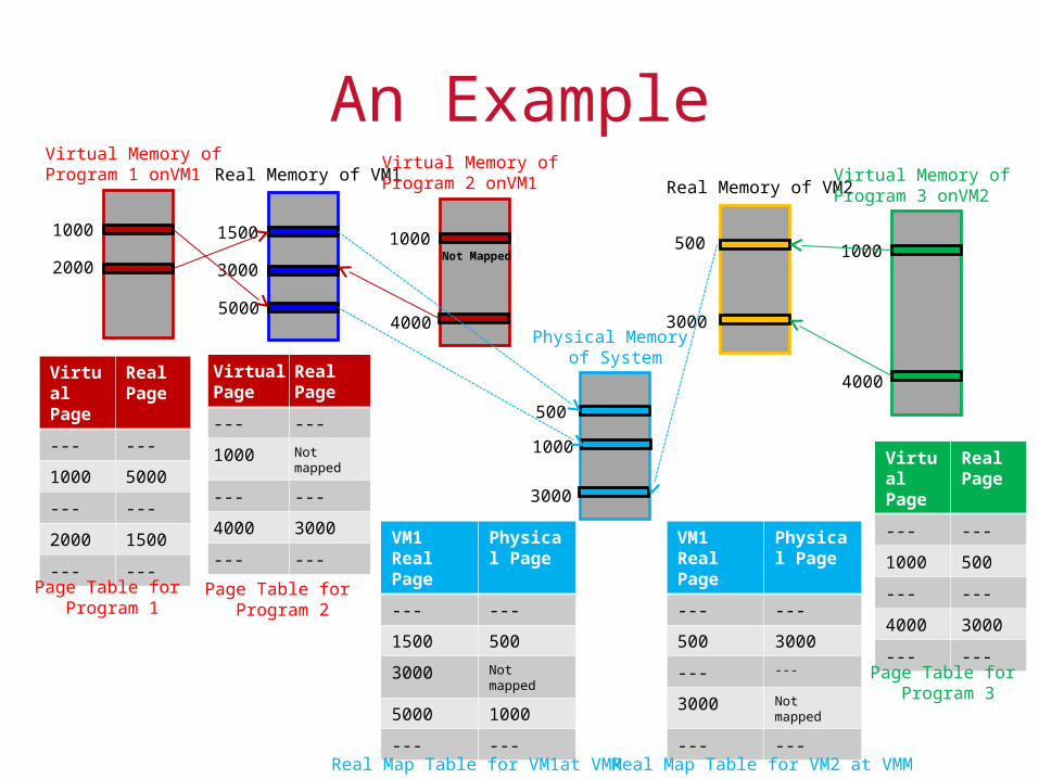
An Example
1000
2000
Virtual Memory of Program 1 onVM1
1500
3000
5000
Real Memory of VM1
1000
4000
Virtual Memory of Program 2 onVM1
Not Mapped
Real Memory of VM2
1000
4000
Virtual Memory of Program 3 onVM2
500
3000
500
3000
Physical Memory of System
1000
Virtual Page
Real Page
--- ---
1000 5000
--- ---
2000 1500
--- ---
Virtual Page
Real Page
--- ---
1000 Not mapped
--- ---
4000 3000
--- ---
Page Table for Program 1
Page Table for Program 2
Virtual Page
Real Page
--- ---
1000 500
--- ---
4000 3000
--- ---
Page Table for Program 3
VM1 Real Page
Physical Page
--- ---
1500 500
3000 Not mapped
5000 1000
--- ---
Real Map Table for VM1at VMM
VM1 Real Page
Physical Page
--- ---
500 3000
--- ---
3000 Not mapped
--- ---
Real Map Table for VM2 at VMM
Resource Virtualization
41
Resource Virtualization
CPU Virtualization I/O VirtualizationMemory Virtualization
I/O Virtualization
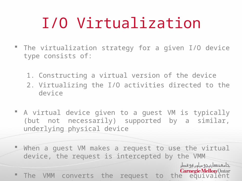
The virtualization strategy for a given I/O device type consists of:
1. Constructing a virtual version of the device
2. Virtualizing the I/O activities directed to the device
A virtual device given to a guest VM is typically (but not necessarily) supported by a similar, underlying physical device
When a guest VM makes a request to use the virtual device, the request is intercepted by the VMM
The VMM converts the request to the equivalent request understood by the underlying physical device and sends it out
Virtualizing Devices
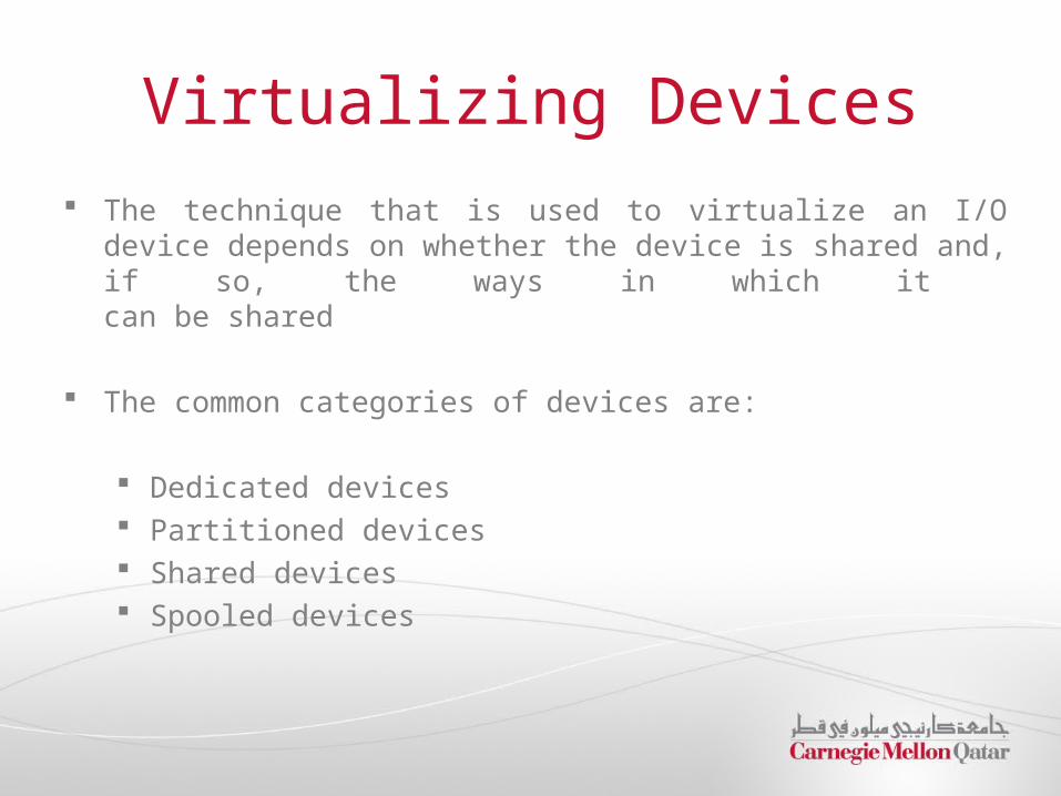
The technique that is used to virtualize an I/O device depends on whether the device is shared and, if so, the ways in which it can be shared
The common categories of devices are:
Dedicated devices Partitioned devices Shared devices Spooled devices
Dedicated Devices
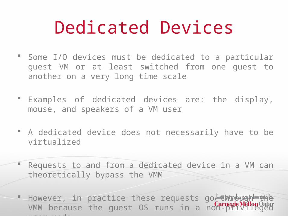
Some I/O devices must be dedicated to a particular guest VM or at least switched from one guest to another on a very long time scale
Examples of dedicated devices are: the display, mouse, and speakers of a VM user
A dedicated device does not necessarily have to be virtualized
Requests to and from a dedicated device in a VM can theoretically bypass the VMM
However, in practice these requests go through the VMM because the guest OS runs in a non-privileged user mode
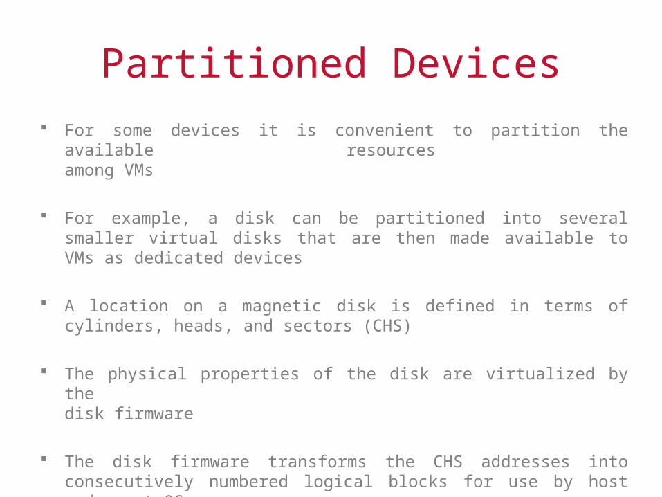
Partitioned Devices For some devices it is convenient to partition the available resources
among VMs
For example, a disk can be partitioned into several smaller virtual disks that are then made available to VMs as dedicated devices
A location on a magnetic disk is defined in terms of cylinders, heads, and sectors (CHS)
The physical properties of the disk are virtualized by the disk firmware
The disk firmware transforms the CHS addresses into consecutively numbered logical blocks for use by host and guest OSs
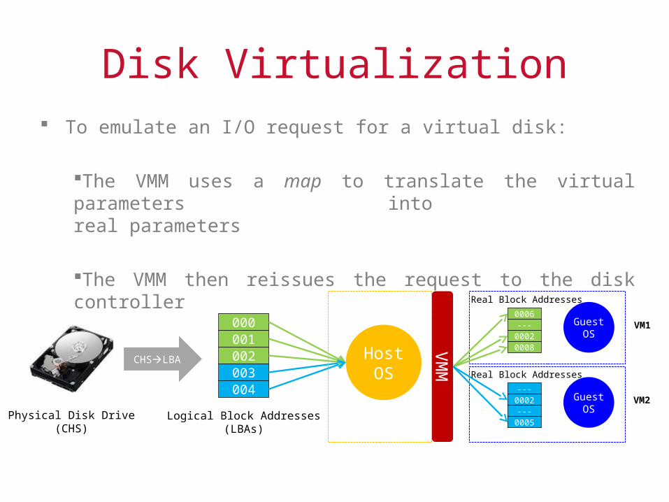
Disk Virtualization To emulate an I/O request for a virtual disk:
The VMM uses a map to translate the virtual parameters into real parameters
The VMM then reissues the request to the disk controller
CHSLBA
000001002003004
Host OS
VM
M
Guest OS
Guest OS
Physical Disk Drive(CHS)
Logical Block Addresses(LBAs)
0006---
00020008
---0002
---0005
Real Block Addresses
Real Block Addresses
VM1
VM2
Shared Devices
Some devices, such as a network adapter, can be shared among a number of guest VMs at a fine time granularity
For example, every VM can have its own virtual network address maintained by the VMM
A request by a VM to use the network is translated by the VMM to a request on a physical network port To make this happen, the VMM uses its own physical network address
and a virtual device driver
Similarly, incoming requests through various ports are translated into requests for virtual network addresses associated with different VMs
Network Virtualization- Scenario I
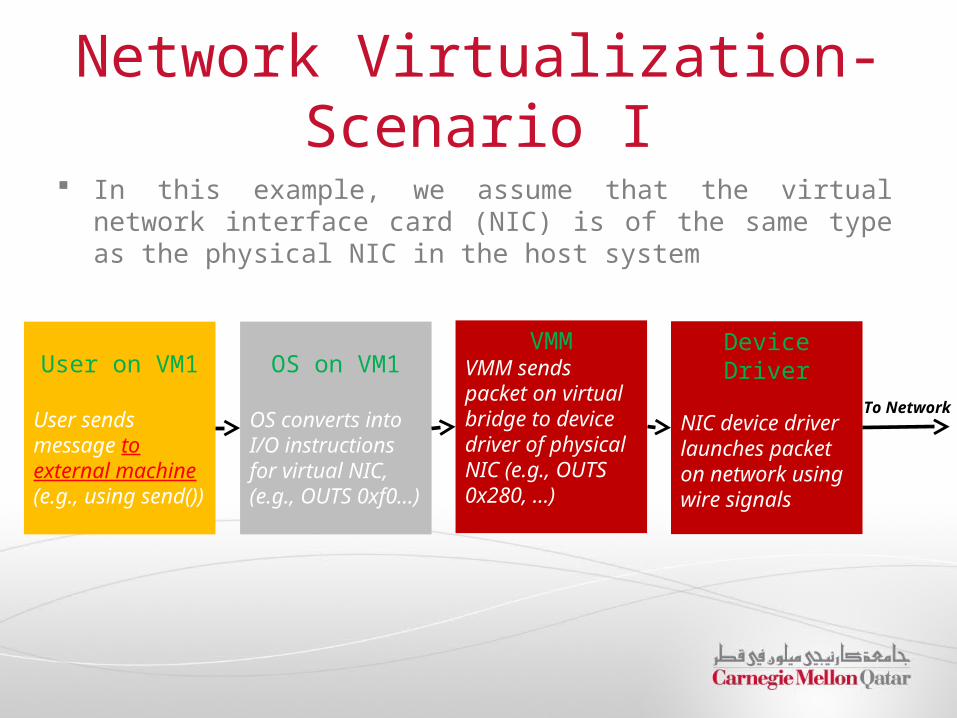
In this example, we assume that the virtual network interface card (NIC) is of the same type as the physical NIC in the host system
User on VM1
User sends message to external machine (e.g., using send())
OS on VM1
OS converts into I/O instructions for virtual NIC, (e.g., OUTS 0xf0…)
VMMVMM sends packet on virtual bridge to device driver of physical NIC (e.g., OUTS 0x280, …)
Device Driver
NIC device driver launches packet on network using wire signals
To Network
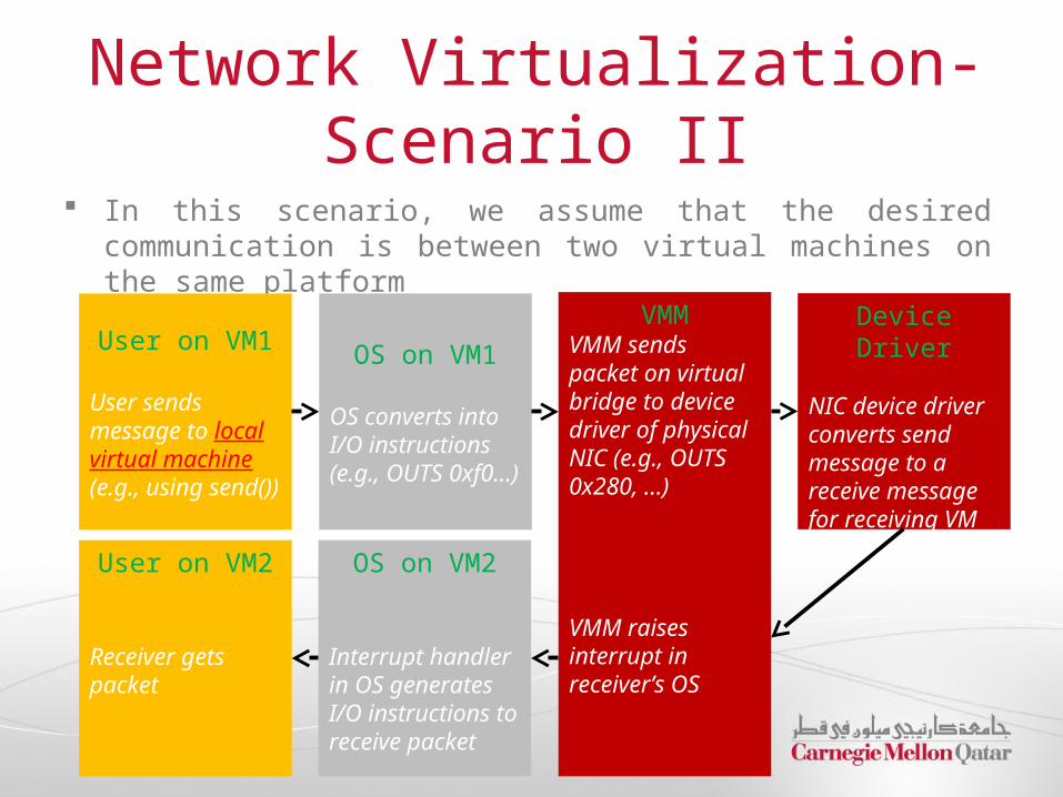
Network Virtualization- Scenario II
In this scenario, we assume that the desired communication is between two virtual machines on the same platform
User on VM1
User sends message to local virtual machine (e.g., using send())
OS on VM1
OS converts into I/O instructions (e.g., OUTS 0xf0…)
VMMVMM sends packet on virtual bridge to device driver of physical NIC (e.g., OUTS 0x280, …)
VMM raises interrupt in receiver’s OS
Device Driver
NIC device driver converts send message to a receive message for receiving VM
OS on VM2
Interrupt handler in OS generates I/O instructions to receive packet
User on VM2
Receiver gets packet
Spooled Devices
A spooled device, such as a printer, is shared, but at a much higher granularity than a device such as a network adapter
Virtualization of spooled devices can be performed by using a two-level spool table approach: Level 1 is within the guest OS, with one table for each active process Level 2 is within the VMM, with one table for each guest OS
A request from a guest OS to print a spool buffer is intercepted by the VMM, which copies the buffer into one of its own spool buffers
This allows the VMM to schedule requests from different guest OSs on the same printer
51
Thank You!