distributed testing of cloud applications using the jata test framework
TRANSCRIPT

Faculty of Industrial Engineering, Mechanical Engineering and
Computer Science
University of Iceland
2011
Faculty of Industrial Engineering, Mechanical Engineering and
Computer Science
University of Iceland
2011
Distributed Testing of Cloud Applications
Using the Jata Test Framework
Hlöðver Tómasson


DISTRIBUTED TESTING OF CLOUD
APPLICATIONS USING THE JATA TEST
FRAMEWORK
Hlöðver Tómasson
30 ECTS thesis submitted in partial ful�llment of aMagister Scientiarum degree in Computer Science
Advisors
Helmut Wolfram Neukirchen
Helgi Þorbergsson
Faculty Representative
Hjálmtýr Hafsteinsson
Faculty of Industrial Engineering, Mechanical Engineering and
Computer Science
School of Engineering and Natural Sciences
University of Iceland
Reykjavik, May 2011

Distributed Testing of Cloud Applications Using the Jata Test Framework
30 ECTS thesis submitted in partial ful�llment of a M.Sc. degree in Computer Sci-ence
Copyright c© 2011 Hlöðver TómassonAll rights reserved
Faculty of Industrial Engineering, Mechanical Engineering andComputer ScienceSchool of Engineering and Natural SciencesUniversity of IcelandHjarðarhagi 2-6107, Reykjavík, ReykjavikIceland
Telephone: 525 4000
Bibliographic information:Hlöðver Tómasson, 2011, Distributed Testing of Cloud Applications Using the Jata TestFramework, M.Sc. thesis, Faculty of Industrial Engineering, Mechanical Engineering andComputer Science, University of Iceland.
Printing: Háskólaprent, Fálkagata 2, 107 ReykjavíkReykjavik, Iceland, May 2011


Abstract
Cloud computing is becoming a viable and common choice for software infrastruc-tures. Quality assurance such as testing is an important aspect of any product andtechnology. With a new technology new challenges are introduced to quality assur-ance. Thus, software testing research is lacking in following the fast growing trendsof the cloud computing industry.
The thesis investigates the challenges of software testing in elastic cloud computingenvironments and the applicability of the Jata test framework for testing distributedcloud applications. Jata uses concepts from the Testing and Test Control Notationversion 3 (TTCN-3) to implement distributed test cases in Java. A cloud applicationcase study has been performed in this thesis. It reveals that there are speci�cconsiderations to be made for testing of cloud applications to deal with the elasticnature of clouds. The work furthermore suggests that Jata is a promising frameworkfor distributed testing, whether for cloud or non-cloud deployments.


Ágrip
Tölvuský eru orðin raunhæfur og algengur kostur fyrir hýsingu tölvukerfa. Pró-fanir eru mikilvægur þáttur gæðatryggingar á tæknivörum og þjónustu. Með nýrritækni fylgja ætíð nýjar áskoranir fyrir gæðatryggingu, en rannsóknir á sviði hugbú-naðarprófana má segja að skorti samfara hinni örri þróun tölvuskýja.
Í ritgerðinni eru áskoranir hugbúnaðarprófana í tengslum við tölvuský ígrundaðarog notagildi Jata prófanaker�sins athugað í þeim tilgangi. Jata notar hugtök fráTTCN-3 staðlinum (Testing and Test Control Notation version 3) sem grunn til aðstyðja útfærslu dreifðra hugbúnaðarprófana. Tilraun þar sem Jata er notað til aðútbúa tölvuskýprófanir er framkvæmd og lýst í þessari ritgerð. Rannsóknin leiðirí ljós atriði sem þarf að hafa sérstaklega í huga við tölvuskýsprófanir til dæmis tilað bregðast við aðstæðum vegna slembiúthlutunar tölvuskýja á IP netvistföngum.Niðurstöðurnar sýna ennfremur að Jata er áhugaverður kostur fyrir hönnun og út-færslu dreifðra prófa, hvort heldur sem er fyrir tölvuský eða hefðbundnar uppset-ningar.

Acknowledgements
This M.Sc. project was carried out at the Faculty of Industrial Engineering, Me-chanical Engineering and Computer Science at the University of Iceland.
Special thanks goes to my supervisor, Associate Professor Dr. Helmut Neukirchen,for professional and enjoyable support. This thesis is inspired by his research andteaching in the �eld of distributed systems and software testing. I also greatlyappreciate Associate Professor Dr. Helgi Þorbergsson's contributions as secondarysupervisor as well as Associate Professor Dr. Hjálmtýr Hafsteinsson's e�orts as fac-ulty representative.
I would like to thank the authors of Jata; Wu, Yang, and Luo � at the BeihangUniversity, Beijing, China � for providing the source code of the Jata frameworkused in this thesis and their valuable assistance at the early stages of the research.Thanks goes also to Ragnar Skulason M.Sc. student � at the University of Iceland� for providing the source code and assistance for the distributed cloud applicationused in this thesis case study.
Furthermore, my gratitude goes to my professors at the University of Iceland andthe Lund University, Sweden, for providing the foundations this work is based on.Last, but not least, I would like to thank my family for their support and patiencethroughout my studies.
Reykjavík, 18. May 2011.
Hlöðver Tómasson


Contents
List of Figures xv
List of Tables xvii
1. Introduction 11.1. Scope of this Thesis . . . . . . . . . . . . . . . . . . . . . . . . . . . . 21.2. Structure of this Thesis . . . . . . . . . . . . . . . . . . . . . . . . . . 2
2. Foundations 52.1. Cloud Computing . . . . . . . . . . . . . . . . . . . . . . . . . . . . . 5
2.1.1. De�nition . . . . . . . . . . . . . . . . . . . . . . . . . . . . . 52.1.2. Cloud Service Models . . . . . . . . . . . . . . . . . . . . . . . 62.1.3. Elastic and Auto-Scaling . . . . . . . . . . . . . . . . . . . . . 82.1.4. Cloud Deployment Models . . . . . . . . . . . . . . . . . . . . 82.1.5. Challenges . . . . . . . . . . . . . . . . . . . . . . . . . . . . . 92.1.6. Grid Computing . . . . . . . . . . . . . . . . . . . . . . . . . 102.1.7. High Performance Computing (HPC) in the Cloud . . . . . . 112.1.8. Distributed Systems . . . . . . . . . . . . . . . . . . . . . . . 12
2.2. Amazon Cloud Services . . . . . . . . . . . . . . . . . . . . . . . . . . 132.2.1. Amazon Web Services (AWS) . . . . . . . . . . . . . . . . . . 132.2.2. Amazon Elastic Compute Cloud (EC2) . . . . . . . . . . . . . 132.2.3. Amazon Data Storage . . . . . . . . . . . . . . . . . . . . . . 152.2.4. Eucalyptus . . . . . . . . . . . . . . . . . . . . . . . . . . . . 17
2.3. Software Testing . . . . . . . . . . . . . . . . . . . . . . . . . . . . . 172.3.1. Fundamentals of Software Testing . . . . . . . . . . . . . . . . 172.3.2. Veri�cation and Validation . . . . . . . . . . . . . . . . . . . . 182.3.3. Types of Testing . . . . . . . . . . . . . . . . . . . . . . . . . 182.3.4. Testing Distributed Systems . . . . . . . . . . . . . . . . . . . 192.3.5. Testing Cloud Applications . . . . . . . . . . . . . . . . . . . 202.3.6. Cloud Testing Tools . . . . . . . . . . . . . . . . . . . . . . . 212.3.7. Test Documentation . . . . . . . . . . . . . . . . . . . . . . . 23
2.4. The Test Language TTCN-3 . . . . . . . . . . . . . . . . . . . . . . . 242.4.1. Conformance Testing Methodology and Framework . . . . . . 252.4.2. TTCN-3 Concepts . . . . . . . . . . . . . . . . . . . . . . . . 26
xi

Contents
2.5. The Jata Test Framework . . . . . . . . . . . . . . . . . . . . . . . . 312.5.1. Jata vs. JUnit . . . . . . . . . . . . . . . . . . . . . . . . . . . 322.5.2. Jata's Meta-Model for Distributed Testing . . . . . . . . . . . 322.5.3. Jata and TTCN-3 Comparison . . . . . . . . . . . . . . . . . . 34
3. Related Work 413.1. Testing in the Cloud . . . . . . . . . . . . . . . . . . . . . . . . . . . 423.2. Testing of the Cloud . . . . . . . . . . . . . . . . . . . . . . . . . . . 433.3. Migrating Testing to the cloud . . . . . . . . . . . . . . . . . . . . . . 45
4. Testing Cloud Applications 474.1. Cloud Application Under Test . . . . . . . . . . . . . . . . . . . . . . 47
4.1.1. Image Rendering . . . . . . . . . . . . . . . . . . . . . . . . . 484.1.2. Cloud Support for Sun�ow . . . . . . . . . . . . . . . . . . . . 484.1.3. Turnip Rendering Application for the Cloud . . . . . . . . . . 504.1.4. Amazon Machine Image . . . . . . . . . . . . . . . . . . . . . 54
4.2. Test Plan . . . . . . . . . . . . . . . . . . . . . . . . . . . . . . . . . 554.2.1. Introduction . . . . . . . . . . . . . . . . . . . . . . . . . . . . 554.2.2. Test items . . . . . . . . . . . . . . . . . . . . . . . . . . . . . 564.2.3. Features to be tested . . . . . . . . . . . . . . . . . . . . . . . 574.2.4. Features not to be tested . . . . . . . . . . . . . . . . . . . . . 584.2.5. Approach . . . . . . . . . . . . . . . . . . . . . . . . . . . . . 584.2.6. Item pass/fail criteria . . . . . . . . . . . . . . . . . . . . . . . 584.2.7. Test environment . . . . . . . . . . . . . . . . . . . . . . . . . 58
4.3. Test Design . . . . . . . . . . . . . . . . . . . . . . . . . . . . . . . . 604.3.1. Conceptual Test Architecture . . . . . . . . . . . . . . . . . . 604.3.2. Features to be Tested - Conceptual Test Scenario . . . . . . . 624.3.3. Concrete Test Architecture Using Worker Test Double . . . . 644.3.4. Concrete Test Scenario . . . . . . . . . . . . . . . . . . . . . . 65
4.4. Test Case Speci�cations . . . . . . . . . . . . . . . . . . . . . . . . . 684.4.1. Introduction . . . . . . . . . . . . . . . . . . . . . . . . . . . . 684.4.2. Test Case Structure . . . . . . . . . . . . . . . . . . . . . . . . 69
4.5. Test Procedure . . . . . . . . . . . . . . . . . . . . . . . . . . . . . . 84
5. Evaluation 895.1. Software Testing of Cloud Applications . . . . . . . . . . . . . . . . . 895.2. Jata . . . . . . . . . . . . . . . . . . . . . . . . . . . . . . . . . . . . 90
6. Conclusion 936.1. Summary . . . . . . . . . . . . . . . . . . . . . . . . . . . . . . . . . 936.2. Outlook . . . . . . . . . . . . . . . . . . . . . . . . . . . . . . . . . . 94
Acronyms 95
Bibliography 97
xii
Contents
A. Appendix 103A.1. Development Environment Setup . . . . . . . . . . . . . . . . . . . . 103
A.1.1. Download source code from SVN . . . . . . . . . . . . . . . . 103A.1.2. Install the AWS Toolkit for Eclipse . . . . . . . . . . . . . . . 104A.1.3. Import to Eclipse . . . . . . . . . . . . . . . . . . . . . . . . . 104A.1.4. Provide Amazon EC2 credentials . . . . . . . . . . . . . . . . 105A.1.5. Con�gure Amazon EC2 �rewall . . . . . . . . . . . . . . . . . 105A.1.6. Build and Package Turnip . . . . . . . . . . . . . . . . . . . . 106A.1.7. Upload Turnip Files to an HTTP Server . . . . . . . . . . . . 106A.1.8. Execute Jata Test Harness . . . . . . . . . . . . . . . . . . . . 108
A.2. Software Tools Used . . . . . . . . . . . . . . . . . . . . . . . . . . . 109A.3. Jata Test Cases source . . . . . . . . . . . . . . . . . . . . . . . . . . 109A.4. Jata Core Changes (if needed) . . . . . . . . . . . . . . . . . . . . . . 109
xiii

List of Figures
2.1. Cloud service types . . . . . . . . . . . . . . . . . . . . . . . . . . . . 7
2.2. The AWS management console . . . . . . . . . . . . . . . . . . . . . 14
2.3. Types of testing [53] . . . . . . . . . . . . . . . . . . . . . . . . . . . 19
2.4. Hybrid cloud example for a software test lab . . . . . . . . . . . . . . 22
2.5. CTMF multi-party test architecture [50] . . . . . . . . . . . . . . . . 25
2.6. Conceptual view of a typical TTCN-3 test con�guration [1] . . . . . . 27
2.7. Example TTCN-3 port communication setup . . . . . . . . . . . . . . 28
2.8. Illustration of alternative behavior in TTCN-3 [1] . . . . . . . . . . . 30
2.9. Illustration of the relationship between verdicts in TTCN-3 [1] . . . . 31
2.10. Jata's meta-model [60] . . . . . . . . . . . . . . . . . . . . . . . . . . 33
3.1. Google trends diagram [57] . . . . . . . . . . . . . . . . . . . . . . . . 42
4.1. 3D view af a scene [39] . . . . . . . . . . . . . . . . . . . . . . . . . . 48
4.2. Rendering results [39] . . . . . . . . . . . . . . . . . . . . . . . . . . . 48
4.3. Turnip rendering application in the cloud . . . . . . . . . . . . . . . . 49
4.4. Turnip web management console . . . . . . . . . . . . . . . . . . . . . 50
4.5. Turnip application architecture . . . . . . . . . . . . . . . . . . . . . 51
4.6. Rendering job scenario . . . . . . . . . . . . . . . . . . . . . . . . . . 52
xv

LIST OF FIGURES
4.7. Deployment diagram for Turnip [55] . . . . . . . . . . . . . . . . . . . 53
4.8. Application components . . . . . . . . . . . . . . . . . . . . . . . . . 56
4.9. Integration testing of application components . . . . . . . . . . . . . 57
4.10. The test bed . . . . . . . . . . . . . . . . . . . . . . . . . . . . . . . . 60
4.11. System architecture . . . . . . . . . . . . . . . . . . . . . . . . . . . . 61
4.12. Detailed test architecture . . . . . . . . . . . . . . . . . . . . . . . . . 62
4.13. Conceptual test sequence diagram . . . . . . . . . . . . . . . . . . . . 63
4.14. Worker test double implementation . . . . . . . . . . . . . . . . . . . 65
4.15. Concrete test sequence diagram . . . . . . . . . . . . . . . . . . . . . 66
4.16. Dummy image result . . . . . . . . . . . . . . . . . . . . . . . . . . . 68
4.17. Test harness utility . . . . . . . . . . . . . . . . . . . . . . . . . . . . 85
4.18. Test case result view (log) . . . . . . . . . . . . . . . . . . . . . . . . 85
A.1. Test harness utility . . . . . . . . . . . . . . . . . . . . . . . . . . . . 108
xvi

List of Tables
2.1. Amazon on-demand instance types (May 7, 2011) . . . . . . . . . . . 16
2.2. Level test chapters used from IEEE Std 829-2008 . . . . . . . . . . . 23
2.3. IEEE Std 829-2008 concepts used for the case study documentation . 24
2.4. Adopted TTCN-3 concepts in Jata . . . . . . . . . . . . . . . . . . . 35
3.1. Literature search results . . . . . . . . . . . . . . . . . . . . . . . . . 41
4.1. Run-time software for the case study application . . . . . . . . . . . . 54
4.2. Amazon 'Small' instance type (May 7, 2011) . . . . . . . . . . . . . . 59
4.3. Ordered activities description . . . . . . . . . . . . . . . . . . . . . . 87
4.4. Test activities execution times . . . . . . . . . . . . . . . . . . . . . . 87
A.1. Eclipse Java projects for the case study . . . . . . . . . . . . . . . . . 104
A.2. Amazon EC2 Ports . . . . . . . . . . . . . . . . . . . . . . . . . . . . 105
A.3. Software used for the case study . . . . . . . . . . . . . . . . . . . . . 109
xvii

1. Introduction
Cloud computing is a relatively new concept which has been emerging rapidly as analternative to traditional data-centers, grids, and private clusters. Cloud computingcan be seen as a new way of outsourcing hardware and software services, and itpromises that any organization can extend their IT infrastructure in a simple ande�cient way. It also promises to help new businesses by requiring less upfront capitalexpenses for IT infrastructure.
Though cloud computing o�ers the potential to improve productivity and reducecosts it also poses many new challenges such as security and legal considerations,technical challenges, including software testing challenges. There are various techni-cal challenges that need to be considered when doing research for cloud integrationand it is far from trivial to integrate infrastructures to cloud models in a scalable andsecure way. The construction of distributed systems within clouds poses numerouschallenges on development and testing, because of their diversity and complexity. Amultitude of di�erent sub-systems and protocols make up a single distributed sys-tem, and thus implementing and maintaining a distributed system is error-prone.Reliability issues such as security, scalability, failure handling, concurrency, andnetwork related issues such as latency and throughput are all non-trivial testingobjectives. It is furthermore extremely di�cult to test all possible system con�gura-tions where the software will be executed i.e. di�erent operating systems, hardware,and software versions.
Software testing is a critical part of the quality assurance in software systems devel-opment. It is one of the most challenging and costly process activities. Research andexperience show that software testing provides a strong support for the developmentof high quality software. Security and technical challenges of cloud computing havereceived a good focus in academic and commercial literature. Software testing ofcloud applications has unfortunately not been as well addressed. The goal of thisthesis is to improve on this.
1

1. Introduction
1.1. Scope of this Thesis
The main goal of the thesis is investigation of the challenges imposed on softwaretesting for cloud applications. For this work the Jata test framework [60] is used ina case study to implement test cases for a cloud application. Jata has recently beencreated to support distributed component testing. It is a Java framework whichincludes a meta-model for de�ning and structuring test cases. The meta-model usesconcepts from the standardized testing language TTCN-3 (Testing and Test ControlNotation version 3 ). Therefore an additional research goal was made to evaluate theapplicability of Jata for advanced distributed testing like in a cloud environment.
Cloud computing is not a fundamentally new paradigm. It is based on existingdistributed technologies such as utility computing and Software-as-a-Service (SaaS).Much of the testing of cloud applications can be done with traditional distributedtesting methods regardless of the type of hardware or network infrastructure in use.
This thesis is largely inspired by Grid application testing methods introduced byRings, Neukirchen and Grabowski in Testing Grid Application Work�ows UsingTTCN-3 [50]. In their work TTCN-3 is used for de�ning and implementing testcases for a distributed application running in a Grid environment. The focus oftheir work is testing of the distribution management aspects of the system undertest, as is also the focus in this thesis. Jata uses TTCN-3 concepts and therefore itis possible to use test structure ideas from the previous grid testing work.
This thesis focuses on black-box functional testing of distributed computing systemsusing the Jata test framework. A case study was made where a distributed parallelapplication was tested within the Amazon EC2 cloud environment. A parallel appli-cation, which carries out computing concurrently on multiple machines, was chosenin order to use advanced testing techniques. The objectives are to reveal what as-pects of cloud computing need to be considered and addressed when doing softwaretesting of cloud applications, and furthermore to evaluate the Jata framework fordistributed testing.
1.2. Structure of this Thesis
An outline of the thesis is given in the following: After this introduction, the foun-dations for this thesis are given in Chapter 2. This includes an overview of cloudcomputing and the Amazon cloud services which are used in this thesis. Furthermorethe chapter includes an overview of software testing, the Testing and Test ControlNotation version 3 (TTCN-3), and the Jata test framework used in the case study.
2

1.2. Structure of this Thesis
Chapter 3 contains discussion of related work for this thesis. Literature on softwaretesting of cloud application is unfortunately still lacking and this chapter surveysthe work that relates to testing and cloud computing, even though the relationshipwith this thesis topic is not strong. The chapter is divided into three categories:Testing in the cloud, testing of the cloud, and migrating testing to the cloud.
The main contribution, a case study for testing a cloud application, is described inChapter 4. The chapter describes the design and implementation of a black-box testcase for a cloud application using Jata. The chapter begins with an overview of theTurnip application that is under test in the case study. The Turnip application isa cloud extension of the open-source Sun�ow image rendering system. The man-agement of the distributed application is the focus of the testing. In later sectionsof the chapter the test plan, test design and test case speci�cation with Jata arecovered in detail.
Subsequently, in Chapter 5, an evaluation is made concerning both software testingof cloud applications and the Jata test framework. The evaluation is based on theresults of the case study.
Finally, a summary, and an outlook are given as a conclusion in Chapter 6. Thisthesis is completed by a list of acronyms and the referenced bibliography. An ap-pendix on the setup of the development environment for the case study is at the endof the thesis.
3


2. Foundations
In this chapter background information is provided on Cloud Computing in Section2.1. Section 2.2 contains a description of the Amazon Elastic Compute Cloud (EC2)which is used as the cloud platform for the case study in this thesis. Finally, inSection 2.3, Software Testing is covered.
2.1. Cloud Computing
Cloud Computing is a relatively new concept which has been emerging as an alterna-tive to traditional data-centers, grids, and private clusters. It can help organizationsto start businesses with less upfront capital expenses for IT infrastructure. It alsogives the ability to scale the IT infrastructure, up or down, more easily and e�cientlyalongside the organization's growth.
Cloud computing is however not fundamentally a new paradigm. It is based onexisting distributed technologies such as utility computing and Software-as-a-Service(SaaS). It can be seen as a new way of outsourcing hardware and software services,and it promises that any organization can extend their IT structure in a simple ande�cient way.
2.1.1. De�nition
Though it seems impossible to agree on a single de�nition for cloud computing, theseemingly most acceptable one today is provided by the U.S. National Institute ofStandards and Technology (NIST):
Cloud computing is a model for enabling convenient, on-demand networkaccess to a shared pool of con�gurable computing resources (e.g., net-works, servers, storage, applications, and services) that can be rapidlyprovisioned and released with minimal management e�ort or serviceprovider interaction. This cloud model promotes availability and is com-posed of �ve essential characteristics, three service models, and four de-ployment models. [41]
5

2. Foundations
The �ve essential characteristics are On-demand self-service, Broad network access,Resource pooling, Rapid elasticity, and Measured Service. The cloud service modelsand deployment models are covered in sections 2.1.2 and 2.1.4.
Another new and widely used de�nition comes from the UC Berkeley Reliable Adap-tive Distributed Systems Laboratory (RAD lab):
Cloud Computing refers to both the applications delivered as servicesover the Internet and the hardware and systems software in the data-centers that provide those services. The services themselves have longbeen referred to as Software as a Service (SaaS). The data-center hard-ware and software is what we will call a Cloud. When a Cloud is madeavailable in a pay-as-you-go manner to the general public, we call ita Public Cloud; the service being sold is Utility Computing. We usethe term Private Cloud to refer to internal data-centers of a businessor other organization, not made available to the general public. Thus,Cloud Computing is the sum of SaaS and Utility Computing, but doesnot include Private Clouds. [7]
Many other de�nitions of cloud computing are available and substantial work hasbeen done to come up with a single de�nition, e.g. Vaquero et al. [58] and the workof an expert group of 21 individuals [24]. Most of the de�nitions, as the two above,harmonize well with the version of Vaquero et al. of a minimum de�nition whichgroups a set of three common features for the di�erent cloud computing de�nitions:
Scalability, pay-per-use utility model and virtualization. [58]
The keyword in cloud computing is virtualization, which makes it possible for cloudcustomers to dynamically scale their computing resources, such as storing and pro-cessing capacity, to build tailored systems in an on-demand manner, paying only forthe resources needed.
2.1.2. Cloud Service Models
Cloud services are mainly divided into three services delivery models [41, 58], wherehardware and platform resources are provided as services in an on-demand way:
• Software as a Service (SaaS)
• Platform as a Service (PaaS)
• Infrastructure as a Service (IaaS)
6
2.1. Cloud Computing
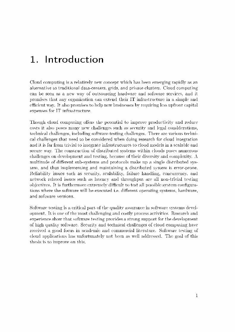
Figure 2.1 depicts the nature of the cloud services by comparing the levels of technol-ogy stacks provided by the di�erent service types. The service type de�nitions repre-sent the separation between the responsibilities of the consumer and the provider ofthe services. In case of SaaS the complete software stack is provided by the vendor,but in the other two cases it is the responsibility of the consumer to provide theremainder of the stack.
Figure 2.1: Cloud service types
Software as a Service
In the SaaS model the whole software stack is provided by the cloud environment;from hardware, to operating systems, to end user applications. This is an alternativeto locally executed software applications and the only client software needed is a webbrowser. An example of SaaS is the on-line versions of typical o�ce applicationssuch as word processors and spreadsheet applications. A well known SaaS provider isGoogle with its Google Apps including Google Docs and Google Mail. Another majorSaaS provider is Salesforce.com1 which provides on-demand customer relationshipmanagement software (CRM).
Platform as a Service
The PaaS service type provides a software platform for systems, including operat-ing systems, middleware and software development frameworks for developing ap-plications on an abstract platform. Example of PaaS providers and solutions areMicrosoft Windows Azure and Google App Engine.
1Salesforce.com, inc. http://www.salesforce.com/
7
2. Foundations
Infrastructure as a Service
This IaaS model is basically a hardware-renting service where consumers can requestcomputer resources and are billed based on the actual time of usage. The consumeris responsible of maintaining the software on the rented machines, including theoperating system. Example IaaS providers are Amazon2, Eucalyptus3, RackSpace4,and GoGrid5.
This thesis focuses on software testing for applications within the IaaS model, anduses Amazon's Elastic Compute Cloud (EC2) platform as the cloud infrastructureof the test-bed.
2.1.3. Elastic and Auto-Scaling
Cloud services are elastic by nature where the number of resources are controllable atany point in time. Organizations extend or shrink its infrastructure by launching orterminating virtual machines which are called instances. One of the main objectivesof cloud services is the ability to respond quickly to di�erent loads and scale resourceseither up or down automatically.
The auto-scaling feature is especially valuable for applications that have unpre-dictable spikes in load on a regular (or irregular) basis, which allows them to beprepared and extend the resources they need on-demand. In contrast to traditionalhosting, where a �xed number of resources are provided for a �xed amount of time,and any changes of load can mean problems. In that case the only way for organi-zations to secure themselves is by adding extra �xed resources to handle the peaks,leading to wasted resources in regular hours. Using cloud technology it is possible tobe prepared for unexpected spikes in the load and utilization of resources thereforebecomes more e�cient.
2.1.4. Cloud Deployment Models
According to NIST's de�nition [41] the four cloud deployment models are:
• Private cloud
• Community cloud
2Amazon EC2. http://aws.amazon.com/ec2/3Eucalyptus Systems, Inc. http://www.eucalyptus.com/4Rackspace, US Inc. http://www.rackspace.com/5GoGrid. http://www.gogrid.com/
8

2.1. Cloud Computing
• Public cloud
• Hybrid cloud
The selection of cloud deployment model depends on the di�erent levels of securityand control required.
The Private cloud infrastructure is operated solely for a single organization withthe purpose of securing services and infrastructure on a private network. This de-ployment model o�er the greatest level of security and control, but it requires theoperating organization to purchase and maintain the hardware and software infras-tructure, which reduces the cost saving bene�ts of investing in a cloud infrastructure.Rackspace, Eucalyptus, and VMware6 are example providers of private cloud solu-tions.
A Community cloud infrastructure is shared by several organizations and supportsa speci�c community that has shared concerns. It may be established where organi-zations have similar requirements and seek to share cloud infrastructure. Exampleof community cloud is Google's Gov Cloud.
Public clouds provide services and infrastructure over the Internet to the generalpublic or a large industry group and is owned by an organization selling cloud ser-vices. Major public cloud providers are Google and Amazon. These clouds o�er thegreatest level of e�ciency in shared resources, however they are also more vulnerablethan private clouds.
A Hybrid cloud infrastructure, as the name suggests, is a composition of private,public, and/or community clouds possibly through multiple providers. Reasoningfor hybrid cloud infrastructure is to increase security, better management or fail-over purposes. For some it may not be feasible to place assets in a public cloud,therefore many opt for the value of combining di�erent cloud deployment models.The drawbacks of a hybrid cloud however is the requirements of managing multipledi�erent security platforms and communication protocols.
2.1.5. Challenges
Cloud computing o�ers potential to improve productivity and reduce costs but italso poses many new challenges such as security and legal considerations, technicalchallenges, and software testing challenges.
One of the main concerns for cloud computing are security issues. Some organiza-
6VMware, Inc. http://www.vmware.com/
9

2. Foundations
tion's data might be considered too sensitive to be stored in a non-private cloud.Cloud customers must put trust in the cloud provider hands to not, intentionally norby accident, compromise their data. Even if the nodes of the cloud infrastructuresare secure, data encryption also needs to be in place for the various communicationchannels.
There are numerous technical challenges that need to be considered when doingresearch for cloud integration and it is far from trivial to integrate infrastructures tocloud models in a scalable and secure way. Network problems, such as performanceissues, latency, and data transfer rates can for example be hard to manage.
Security and technical challenges have received good focus in academic and commer-cial literature. Khajeh-Hosseini, Sommerville and Sriram address research challengesfor enterprise cloud computing in the journal paper Research Challenges for Enter-prise Cloud Computing [37], which focuses on security and regulatory issues. Cloudconsultant John Roton describes technical and organizational challenges in his bookCloud Computing Explained [48].
Software testing has however not been quite as well addressed. The aim of thisthesis is to improve this.
2.1.6. Grid Computing
Grid computing can be thought of as cloud computing's technical ancestor. Bothare resource packages (hardware, software, network) to be used on demand. Themain di�erence is that the resources in a grid can be global and provided by manyusers or organizations, while cloud resources are generally only provided by a singleprovider. There are also di�erences in applications to be deployed to the two di�erentinfrastructures. Grids are typically used for scienti�c computing while clouds arefor business.
Coulouris et al. describe the 'Grid' as a middleware that is designed to enable thesharing of resources such as �les, computers, software, data and sensors on a verylarge scale. The resources are shared typically by groups of users in di�erent orga-nizations who are collaborating on the solution of problems requiring large numbersof computers to solve them [19].
Example application that uses grid technology is the World-Wide Telescopce [26], adata-intensive application shared by the astronomy community. Another example,SETI@home, was created for an experiment in public-resource computing. TheSETI (Search for Extra-Terrestrial Intelligence) application uses personal computersat volunteers' homes to detect intelligent life outside the earth [6].
10

2.1. Cloud Computing
2.1.7. High Performance Computing (HPC) in the Cloud
With the introduction of cloud technology recent case studies show that developersare seeking ways to utilize cloud platforms for scienti�c computing or what is knownas High Performance Computing (HPC). One example is an image processing appli-cation, developed by NASA's Jet Propulsion Laboratory (JPL), which uses AmazonAWS for parallel processing of satellite images7.
However care must be taken in designing and implementing HPC applications forthe cloud. Iosup et al. analyze performance of scienti�c computing applicationswithin di�erent cloud platforms. Their results indicate that the current clouds needan order of magnitude in performance improvement to be useful to the scienti�ccommunity. They point out that the current commercial clouds have been built tosupport web and small database workloads, which are very di�erent from typicalscienti�c computing workloads. Nevertheless they �nd that while current cloudcomputing services are insu�cient for scienti�c computing at large, they may still bea good solution for the scientists who need resources instantly and temporarily [35].
The NEON project (Northern Europe Cloud Computing), a cross-Nordic (Sweden,Norway, Denmark, Finland and Iceland) - project, had the purpose of evaluatingthe usefulness of private versus public cloud services for HPC in the Nordic eSciencecommunity. The project's aim was to review the promises and summarize the overallo�ering cloud computing could give to their community. The project's �ndingsare that private cloud solutions are now not mature enough for a transparent userexperience, which is however expected to be gained by the mid of 2012. It is furtherstated that public clouds, especially Amazon AWS, are in a more mature stagethan private ones but still lack features that are necessary to include for cloudresources in a transparent manner in national infrastructures. Public clouds arealready competitive in the low end for non-HPC jobs (low memory, low numberof cores) on price and public clouds are recommended for non-HPC and some HPCusers. About 20% of the jobs running on the current Nordic eScience supercomputerinfrastructure are potentially suitable for cloud-like technology [20].
Amazon is aware of the resource demand of scienti�cal computing, and they havelaunched special services for HPC8. This new service is claimed to be suited forcomplex computational workloads that are sensitive to network performance or inneed of substantial processing power.
7http://aws.amazon.com/solutions/case-studies/nasa-jpl/8http://aws.amazon.com/about-aws/whats-new/2011/04/07/announcing-amazon-ec2-spot-integration-with-hpc-instances/
11

2. Foundations
2.1.8. Distributed Systems
Cloud computing and distributed systems are closely related. Cloud technology addsnew organizational and technological ways of creating infrastructure for distributedsystems.
Resource sharing of computing power, printers, �les, web pages, and databases isthe motivating factor for creating distributed systems. These systems are every-where and are largely connected together via the Internet. The systems come invarious �avors and are heterogeneous in nature. They can roughly be divided intothree types: distributed information systems, distributed computing systems, anddistributed pervasive/ubiquitous systems [11].
The construction of distributed systems poses many challenges because of theircomplexity and diversity. A multitude of di�erent sub-systems and protocols makeup a single distributed system, and thus implementing and maintaining a distributedsystem is very challenging; attributes such as security, scalability, failure handling,concurrency and transparency must be considered [19].
Distributed systems pose numerous challenges on software testing. Because of thediversity it is extremely di�cult to test all possible system con�gurations where thesoftware will be executed i.e. di�erent operating systems, hardware, and softwareversions. Clustering and load-balancing architectures make matters even more com-plicated. Reliability issues such as fail-over and redundancy and network relatedissues such as latency and through-put are further non-trivial testing objectives.These challenges fall under non-functional testing.
This thesis focuses on functional testing of distributed computing systems, mainly onparallel computation which is a form of computation in which many calculations arecarried out concurrently [4]. Parallel computing is used in di�erent areas as diverseas mathematics, medicine, molecular biology, astrophysics, and image rendering.
12

2.2. Amazon Cloud Services
2.2. Amazon Cloud Services
This thesis deals with software testing in an elastic cloud environment. The researchinvolves launching a distributed application within a cloud environment as a casestudy for software testing. The cloud platform selected for the research was AmazonElastic Compute Cloud (EC2) which is part of Amazon Web Services (AWS).
2.2.1. Amazon Web Services (AWS)
Amazon is arguably a pioneer in o�ering cloud services and AWS has become thede facto standard for cloud infrastructure services. Other IaaS services either com-plement AWS or are considered competitors to them.
The story behind Amazon's rise in the IT sector was that they wanted to �nd waysto make better use of underutilized peak computing power of their on-line retail.High proportion of their sales are processed in the weeks before Christmas. Thecompany's peak day in on-line retail in the year 2010 was November 29, when morethan 13.7 million items where ordered worldwide across all product categories [31],and it takes a tremendous amount of computing power to handle such a load.
Amazon launched AWS in 2002 to turn their IT cost weakness into an opportunity.The initial plan was selling idle capacity to organizations who needed secure andreliable computing infrastructure, at other times than around the Christmas sales.
Today Amazon o�ers a large number of cloud services, with largest attention onAmazon EC2, described in section 2.2.2 and accommodating storage services de-scribed in section 2.2.3.
2.2.2. Amazon Elastic Compute Cloud (EC2)
Amazon Elastic Compute Cloud (Amazon EC2) is the name of the service thatprovides the re-sizable compute capacity, or what is referred to as a cloud. Includedin Amazon EC2 is a set of web services that allows users to launch and manageLinux/UNIX and Windows server instances in Amazon's data centers, and loadthem with custom application environment.
It is possible to commission from one up to thousands of server instances simulta-neously. Public information on on how many instances EC2 customer can reserveat a time is not available, but the default starting limit is twenty reserved instances
13

2. Foundations
that a customer can purchase each month. The limit can be raised by contactingAmazon9.
Amazon provides web user interface for managing cloud resources. Figure 2.2 is asnapshot of the AWS Management console EC2 view. The console provides manage-ment for AWS's compute, storage, and other cloud features. For EC2 managementthe console has options to start and stop EC2 instances and con�gure networkingand security features.
Figure 2.2: The AWS management console
Amazon furthermore provides a software development kit (SDK) for cloud servicemanagement called Amazon AWS SDK. Currently the SDK's API has been im-plemented for Java, Microsoft .NET, PHP, Python, and Ruby. Eclipse users candownload the AWS Toolkit plug-in which makes Java application deployment to in-stances possible from within the Eclipse IDE, plus additional instance managementfeatures [5]. The AWS SDK for Java is used for this thesis' case study, to managecloud instances for the test bed.
9http://aws.amazon.com/contact-us/reserved-instances-limit-request/
14

2.2. Amazon Cloud Services
Amazon Machine Image (AMI)
A core feature of cloud computing is virtualization. Virtual machines in AmazonEC2 are called Amazon Machine Images (AMI). An AMI consists of a read-only�le-system image which includes an operating system and typically some applicationsoftware (e.g. web application or a database).
Amazon provides prepackaged AMIs with Windows and Linux operating systemsinstalled. Various 3rd party vendor also provide prepackaged images, like Ubuntuwhich provides o�cial Ubuntu Linux images on Amazon EC2. Users can also createtheir own images from scratch or extend publicly available images and re-packagethem with new instance IDs.
An AMI can be public, paid, or shared. A public AMI can be used by anyone: Apaid image requires subscription fees, and a shared AMI is private and can only beused by Amazon EC2 users speci�ed by the owner of the image.
Amazon EC2 Hardware Speci�cations and Pricing
The hardware speci�cation for Amazon instances is selected at startup of each in-stance and can be selected from prede�ned a set of instance types de�ned by Amazon(e.g. Small, Large, or Extra Large). The instance type controls what resources theAMI uses; RAM, CPU and disk size. Table 2.1 lists the variations for EC2 instancesand the di�erent prices in USD per hour based on computing power.
The prices shown in the table are for Linux/UNIX usage within the European region.Windows operating system costs are roughly around 10-25% higher for each instancetype. The case study in this thesis uses the standard 'Small' instance type. Thecost for this thesis' research has summed up to be 112.59 USD for 1,186 instancehours.
Amazon provides further pricing options for reserved instances on annual basis orfor spot-priced instances. Pricing details can be �nd on Amazon's EC2 website10.
2.2.3. Amazon Data Storage
Because of EC2's elastic nature permanent data persistence is not possible for AMIs.Amazon provides various di�erent cloud services to address data persistence issuesin the cloud:
10Amazon EC2 Pricing: http://aws.amazon.com/ec2/pricing/
15

2. Foundations
Type RAM CPUs Instance I/O Price/(GB) (EC2) Storage Platform Perform. hour
Micro Instances :Micro 0.613 2 0 GB 32/64-bit Low $0.025
Standard Instances :Small 1.7 1 160 GB 32-bit Moderate $0.095Large 7.5 4 850 GB 64-bit High $0.38ExtraLarge
15 8 1,690 GB 64-bit High $0.76
High-Memory Instances :ExtraLarge
17,1 6.5 420 GB 64-bit Moderate $0.57
DoubleExtraLarge
34,2 13 850 GB 64-bit High $1.14
QuadrupleExtraLarge
68,4 26 1,690 GB 64-bit High $2.28
High-CPU Instances :Medium 1.7 5 350 GB 32-bit Moderate $0.19ExtraLarge
7 20 1,690 GB 64-bit High $0.76
Table 2.1: Amazon on-demand instance types (May 7, 2011)
• Amazon Simple Storage Service (S3) provides a web services interface for stor-ing and retrieve data.
• Amazon Elastic Block Storage (EBS) provides block level storage volumes foruse with Amazon EC2 instances.
• Amazon SimpleDB is a non-relational data store for data queries via webservices.
The di�erence between S3 and SimpleDB is that SimpleDB is meant to be forsmaller amounts of data. SimpleDB was created for performance optimization andin order to minimize costs across AWS services for large objects and �les which arestored in S3. Meta-data associated with those �les is stored in the SimpleDB. It ispossible to run applications in Amazon EC2 and store data objects in Amazon S3.
16

2.3. Software Testing
Amazon SimpleDB can then be used to query the object meta-data from within theapplication in Amazon EC2 and return pointers to the objects stored in AmazonS3. This allows for quicker search and access to objects, while minimizing overallstorage costs.11
2.2.4. Eucalyptus
Eucalyptus (Elastic Utility Computing Architecture for Linking Your Programs ToUseful Systems) is an open-source private cloud infrastructure, which implementsthe Amazon speci�cation for EC2. Eucalyptus conforms to both the syntax and thesemantic de�nition of the Amazon API and tool suite, with few exceptions. Thus itis possible to use the Amazon command-line tools directly for Eucalyptus12.
2.3. Software Testing
This section starts by introducing the fundamentals of software testing, before in-troducing software testing techniques for distributed systems and cloud computing.Common challenges for this area are discussed and what testing methods should beconsidered for testing within cloud environments.
2.3.1. Fundamentals of Software Testing
Software testing is a critical part of the software development process. It is oneof the most challenging and costly process activities, and in its fullest de�nition itprovides strong support for the development of high quality software [15]. Testingobjectives can be seen as twofold:
• Evaluating quality and
• Defect detection
As other quality assurance activities, testing helps ensuring that software is built ontime, within budget, and is of the quality expected, de�ned by quality attributes suchas reliability, usability, performance, and the ability to meet users' requirements.
11Amazon S3 vs. SimpleDB. http://aws.amazon.com/simpledb/#sdb-vs-s312Eucalyptus FAQ. http://open.eucalyptus.com/wiki/FAQ
17

2. Foundations
2.3.2. Veri�cation and Validation
The testing process includes the Veri�cation and Validation (V&V) processes whichare a set of activities whose goal is to foster software quality during the developmentlife-cycle [33]. The processes are de�ned in IEEE Standard Glossary of SoftwareEngineering Terminology [47] as the following, with Boehm's [12] informal de�nitionsof the terms inside brackets.
Veri�cation is the process of determining whether or not the products of a givenphase of the software development cycle ful�ll the requirements establishedduring the previous phase.
(Am I building the product right?)
Validation is the process of evaluating software at the end of the software devel-opment process to ensure compliance with software requirements.
(Am I building the right product?)
Veri�cation and validation are closely related to static- and dynamic testing whereveri�cation is usually associated with activities such as inspections, reviews andwalkthroughs (static testing). Validation on the other hand is usually associatedwith running executable test cases on the code (dynamic testing), which this thesisfocuses on.
2.3.3. Types of Testing
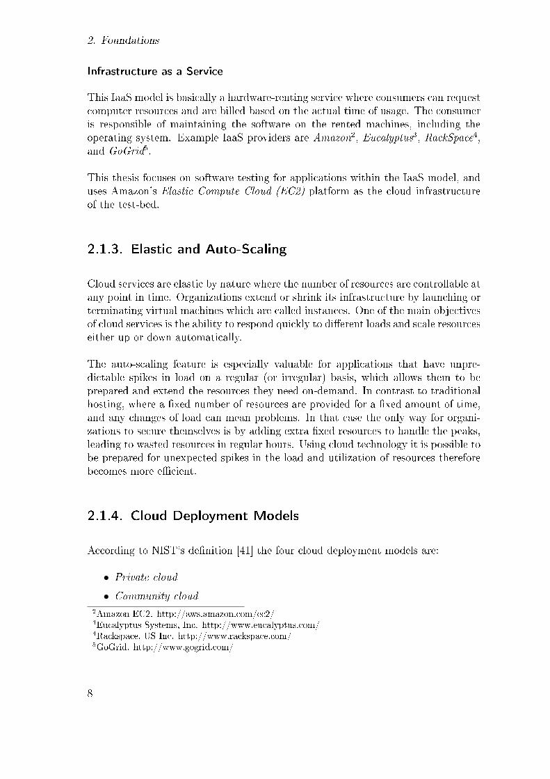
Software testing is a complex activity. Figure 2.3 shows the many dimensions of soft-ware testing which can cover the di�erent stages of a software development project.Di�erent test case design strategies can be used at di�erent testing levels, and thereare many quality attributes of the software to consider when testing.
With black-box testing strategy the software under test is considered to be an opaquebox, with no knowledge of its inner structure. Testers have only knowledge ofwhat the software is supposed to do from the software speci�cations. Black-boxapproaches can be can be used for all levels of testing from unit to acceptance, andare especially useful for revealing requirements and speci�cation defects. Becauseblack-box testing only consider software behavior and functionality, it is often calledfunctional, or speci�cation-based testing.
White-box testing approaches, on the other hand, focus on the inner structure ofthe software under test. White-box approaches are mainly used for unit testing and
18
2.3. Software Testing
up to the integration testing level. They are especially useful for revealing designand code logic defects in elements such as loops, branching and data �ow [14].
It is important that there are several degrees of freedom of what, where, and whenshould be tested in a software system, and the key to successful testing is the se-lection, and the execution, of appropriate methods in each case. This thesis focuseson black-box functional integration testing, for validation of a software applicationrunning in a cloud environment.
Figure 2.3: Types of testing [53]
2.3.4. Testing Distributed Systems
As described in Section 2.1.8, cloud applications can take on the form of varioustypes of distributed systems. Testing of distributed systems focuses on the interac-tion between components of the distributed systems, as opposed to non-distributedtesting which do not usually involve any interaction with other systems or distributedcomponents. In distributed testing, the test system itself is often distributed as well,i.e. test components can be distributed on the di�erent nodes of the system.
Distributed testing should not be confused with remote testing which is a methodto distribute test cases over many machines. No communication is between thedi�erent machines in case of remote testing, even though many machines are usedat once. Those tests do not involve any interaction between the di�erent processorsor the test components of the test cases.
19

2. Foundations
2.3.5. Testing Cloud Applications
When discussing software testing and cloud computing it is bene�cial to distin-guish between the di�erent testing objectives. The Software Testing in the Cloud(STITC)13, a special interest group, categorized the di�erent objectives of cloud test-ing in the following three key areas at the 2nd International Workshop on SoftwareTesting in the Cloud, held in Paris, France in April 2010. The STITC workshopwas co-located with the 3rd IEEE International Conference on Software Testing,Veri�cation, and Validation (ICST 2010).14
1. Testing in the cloud: Leveraging the resources provided by a cloud computinginfrastructure to facilitate the concurrent execution of test cases in a virtual-ized environment.
2. Testing of the cloud: Testing applications that are hosted and deployed in acloud environment.
3. Migrating testing to the cloud: Moving the testing process, test assets, andtest infrastructure from their current state to facilitate either testing in thecloud or testing of the cloud.
Testing in the cloud is about utilizing the cloud for testing, such as for con�gurationtesting and load testing. Software testing of the cloud, the focus of this thesis, isthe least researched area. Very few papers have been published that focus directlyon testing applications in a cloud environment. Migrating testing to the cloud is ahybrid category for the two other categories. Related work for these three categoriesis discussed in Section 3.
Testing of the Cloud
This thesis focuses on testing of the cloud. Much of the testing of cloud applicationscan be done with traditional distributed testing methods regardless of the type ofhardware or network infrastructure in use.
On the system testing level the whole system is tested via its user interface and thetransparency of the clouds should not impose any special requirements of conformingto functional requirements of the software, so testing is not a�ected by the fact theapplication is running within cloud environment. Same system testing approachescan therefore be used as for non-cloud systems. The same goes for the unit testing
13Software Testing in the Cloud (STITC). http://www.stitc.org/14ICST 2010. http://vps.it-sudparis.eu/icst2010/
20

2.3. Software Testing
level where classes are tested in isolation and should not interact with the cloudenvironment. Unit testing can even be run outside the cloud in organization's localtest environment.
Within traditional, fully-controlled, and predictable test-beds IP address allocationis usually not an issue, because the testers know the addresses of each machine usedin the testing. However, the elastic nature of clouds as described in 2.1.3, introducesnew challenges for software testing. This paper addresses issues regarding elasticbehavior of clouds, particularly IP address allocation of virtual machine instances.
The integration testing level, which lies between the unit testing and system testinglevels, is the focus of this thesis. The focus is on the communication on two (or more)di�erent software components which run on two (or more) cloud instances. To beable to test the communication, test components running on each of the involvedcloud instances are needed to perform actions on the components under test. Theproblems for this type of testing have been solved with test technologies such asTTCN-3 and researched for grid application work�ows [50].
This thesis case study uses the Jata test framework [60] which uses concepts ofTTCN-3 for setting up the communication points for the functional black-box inte-gration testing of a cloud application. TTCN-3 and Jata concepts are described insections 2.4 and 2.5 respectively.
For testing within cloud environment there are also various considerations to bemade regarding non-functional requirements. Security testing and privacy-awaretesting probably being at the top of many organizations' list. Substantial amountof work has been done to identify cloud computing security risks and privacy is-sues [27, 56]. Another consideration is performance testing because virtualizationand resource time-sharing may introduce unexpected performance penalties whenapplications are deployed in the cloud.
Testing of non-functional requirements for cloud applications, such as the challengesfor non-functional distributed system testing discussed in Section 2.1.8, are notwithin the scope of this thesis.
2.3.6. Cloud Testing Tools
One area which targets software testing using the cloud, and is widely used, isthe easy access to large clusters of test machines for various purposes, e.g. load-,stress- and performance testing. Several commercial testing tools exist that utilizecloud computing for testing. They can for instance allow automation of functionaland con�guration testing such as cross browser testing of websites with di�erent
21

2. Foundations
browsers and di�erent operating systems. An example tool for this purpose is CloudTesting15.
PushToTest16 can be used within a Continuous Integration [21] environment, wherethe build server can start the cloud testing tool automatically to deploy the systemunder test and the test code to available test nodes in the cloud. The cloud testingframework runs the test cases, collects results and tears down the cloud instancesafterwards.
SOASTA CloudTest17 supports performance and stress testing by leveraging thecompute power o�ered by cloud computing.
Test Lab as a Hybrid Cloud Example
One example of cloud service usage is cost reduction model for hardware and softwarecosts for software company's development- and test labs. The idea is to use ahybrid cloud where the public cloud part is used to satisfy any spikes in load forthe operation of the system's infrastructure. Figure 2.4 shows how the contributedcost can be set to lower levels than the maximum need for the spike loads. In thisexample the cloud infrastructure is a hybrid cloud where the companies test lab isa private cloud but is extended to the public cloud when more resources are neededfor cases such as integration-, load-, stress-, and performance testing.
Public Cloud: On-Demand
Private Cloud: Constant Hardware Cost
Hardware
Time
Performance TestingStress Testing
Figure 2.4: Hybrid cloud example for a software test lab
15Cloud Testing. http://www.cloudtesting.com16PushToTest. http://www.pushtotest.com17SOASTA CloudTest. http://www.soasta.com/cloudtest/
22

2.3. Software Testing
The same argument holds for this cloud infrastructure as a cost reduction model foron-line retail system, where spikes in load are at maximum around Christmas sales.Amazon, the large on-line retailer, went the other way around and decided to makeuse of their peak hardware investments to create services and pro�ts of their regularbasis underutilized computing resources. Amazon created AWS, a large set of webservices, which includes what is now known as one of the largest cloud services,Amazon EC2, as described in Section 2.2.
2.3.7. Test Documentation
For structuring purposes the case study performed in this thesis uses a Software TestPlan approach with added test design and test case details for describing a black-box application testing of a cloud application. The test procedure is furthermorecovered.
A software test plan is a document describing the testing scope, approach, resources,and activities of testing. The test plan holds the basis for formal testing. It identi�esamongst others test items, the features to be tested, the test environment, and thetest design techniques.
The format and content of a software testing documentation can vary depending onthe processes, standards, and testing techniques used. The structure used in Sections4.2 to 4.5 is based on concepts from IEEE Standard for Software and System TestDocumentation (IEEE Std 829-2008) [32], in particular concepts from the Level Testchapters, listed in table 2.2.
IEEE Std 829 - Level Test ChaptersLTP Level Test Plan(s)LTD Level Test DesignLTC Level Test CaseLTPr Level Test Procedure
Table 2.2: Level test chapters used from IEEE Std 829-2008
The sections used from the IEEE level test chapters are listed with comments intable 2.3.
23

2. Foundations
IEEE-829Section
Concept Description
LTP 1 Introduction Provides an overview of the test plan. Speci�esgoals, objectives, and any constraints.
LTP 2.1 Test items List of software/products and their versions.LTP 2.3 Features to be
testedFeatures of the software/product to be tested.
LTP 2.4 Features not tobe tested
Features of the software/product which will not betested, and the reasons.
LTP 2.5 Approach The overall approach to testing. Speci�es the test-ing levels, the testing types, and the testing meth-ods.
LTP 2.6 Item pass/failcriteria
Speci�es the criteria that is used to determinewhether each test item has passed or failed testing.
LTP 3.2 <C 2.5
Test environ-ment
Properties of the test environment: hardware, soft-ware, communications etc.
Table 2.3: IEEE Std 829-2008 concepts used for the case study documentation
2.4. The Test Language TTCN-3
The Testing and Test Control Notation version 3 (TTCN-3) is a test speci�cationand test implementation language that supports black-box functional testing of dis-tributed systems. It also has support for automatic execution of the speci�ed testcases by adding an adaption layer. TTCN-3 can be used for di�erent levels of testingsuch as system-, integration-, and unit testing. It is not only applicable for specify-ing and implementing functional tests, but also for scalability, robustness, or stresstests of huge systems [25, 43].
TTCN-3 originates from the telecommunication domain and it is published as aninternational standard by the ETSI (European Telecommunication Standard Insti-tute) [1]. As a standardized language TTCN-3 is supported by various tools andused by industry and standardization bodies. Powerful tools are available for spec-ifying, deploying, and executing test cases. TTCN-3 is applied in various otherdomains than telecommunication (e.g. data communication, automotive, railway,and �nance). However only one work [50] is known where the language is used inthe �eld of parallel systems [43].
24

2.4. The Test Language TTCN-3
2.4.1. Conformance Testing Methodology and Framework
TTNC-3 is based on concepts of the of the international ISO/IEC standard 9646 OSIConformance Testing Methodology and Framework (CTMF) [36]. CTMF consistsof seven parts for de�ning a comprehensive procedure for the conformance testingof Open Systems Interconnection (OSI) protocol implementations. The di�erentparts contents are: 1) General concepts, 2) test suite speci�cation and test systemarchitectures, 3) test notation, 4) test realization, and 5-7) means of testing andorganizational aspects.
CTMF has been successfully applied for testing distributed telecommunication sys-tems such as ISDN- and GSM-based systems. CTMF concepts were adapted byRings, Neukirchen and Grabowski in Testing Grid Application Work�ows UsingTTCN-3 [50], for functional testing of distributed Grid applications. Part 2 of theCTMF standard, test suite speci�cation and test system architectures, was followed,while other parts were too OSI or conformance testing speci�c to be used for gridtesting.
This thesis uses CTMF's multi-party test architecture, in accordance to [50], totest the parallel application management functionality of a cloud application. Theconceptual test architecture is shown in �gure 2.5.
Figure 2.5: CTMF multi-party test architecture [50]
The system under test (SUT) is made up of the service provider (e.g. cloud or grid)and the implementation under test (IUT). For cloud and grid testing it is assumedthat the service provider has already been adequately tested, and the focus is onthe communication aspects of the application's parallel functionality.
25

2. Foundations
The SUT is controlled by an Upper Tester function (UT) and one or more LowerTester functions (LT). The UT plays the role of a user of the service provided bythe SUT. IUT and the LTs play the role of peer entities, i.e. the LT and the IUTrealize together the service provided to the UT.
The Points of Control and Observation (PCO) are the interfaces used by UTs andLTs to communicate with the SUT. UTs and LTs communicate by means of TestCoordination Procedures (TCP). Further test architectures for distributed sys-tems using CTMF concepts are described in details by Walter, Schieferdecker andGrabowski [59].
2.4.2. TTCN-3 Concepts
This section contains description of TTCN-3 test architecture and language ele-ments. The concepts covered are only subset of the TTCN-3 test language, i.e.those concepts that are relevant for this thesis.
The TTCN-3 language is partly comparable to general programming languages, suchas C++, C#, and Java which include modules, data types, variables, functions, pa-rameters, loops, and conditional statements. However TTCN-3 is based on conceptswhich are independent from general programming languages, such as test cases, testsystems, test verdicts, and test components.
The building-blocks of TTCN-3 are modules, which can be parsed and compiled asseparate entities. A module can include one or more test cases, and describes theexecution sequence of them.
A test case is a complete and independent speci�cation of the actions requiredto achieve a speci�c test purpose. Test cases de�ne the executable behaviors forstimulating the SUT and analyzing the results. In a typical black-box test case, astimulus is sent to a SUT and the response observed to decide whether the SUT haspassed or failed the test.
Test Architecture
TTCN-3 architecture supports distributed testing via Test Components (TC). Notonly may the SUT be distributed or parallel, but also the test itself may consistof several test components that execute test behavior in parallel. A TTCN-3 testsystem consists of one Main Test Component (MTC) and zero or more Parallel TestComponents (PTCs). The MTC's behavior is speci�ed in the body of the test casede�nition. Test components can dynamically create, start, and stop other PTCs.
26

2.4. The Test Language TTCN-3
Each test component runs concurrently and can execute test behavior in parallelwith other test components. Test case execution ends when the MTC terminates.
Test cases are executed by a Test System. A test system con�guration consists of aset of inter-connected test components with well-de�ned communication ports andan explicit test system interface which de�nes the borders of the test system [1].Figure 2.6 shows an overview of a TTCN-3 test system with test components com-municating together via ports and to the SUT through layers of abstract and realtest system interfaces.
Figure 2.6: Conceptual view of a typical TTCN-3 test con�guration [1]
The de�nition of an abstract test system interface (as seen in Figure 2.6) is identicalto a test component de�nition, i.e. it contains communication ports through whichthe test case is connected to the SUT.
The abstract test system interface is described using high-level TTCN-3 code withabstract port de�nitions, whereas the real test system interface is realized by a low-level adaptation layer that implements the ports. The real test system interface, i.e.the physical connections, can be implemented with a programming language suchas Java. The speci�cation and implementation of the real test system interface isoutside the scope of TTCN-3 [1].
When designing test systems with TTCN-3 it is desirable to make the real testsystem interface ports as 'thin' as possible, by implement all test case logic withinthe abstract TTCN-3 layer. That way it is possible to re-use the port implementationfor other test cases.
27

2. Foundations
Communication Ports
For communication between test components or between TCs and the test systeminterface (SUT), ports are used. Each test component has a set of ports whichcontrol in- and out-directions. If two ports are connected, the in-direction of oneport is linked to the out-direction of the other, and vice versa. The out-directionis directly linked to the communication partner, i.e., outgoing information is notbu�ered.
Each port is modeled as an in�nite FIFO queue which stores the incoming messagesor procedure calls until they are processed by the component owning that port.Port connections are created and destroyed dynamically at runtime and there areno restrictions on the number of ports a component may have.
Communication between ports can be message-based and procedure-based commu-nication. Message-based communication (e.g. low-level network messages) is basedon an asynchronous message exchange and the principle of procedure-based commu-nication is to call procedures in remote entities (e.g. high-level procedure or functioncalls). Figure 2.7 shows an example of test case port communication setup for threetest components and a SUT.
Figure 2.7: Example TTCN-3 port communication setup
Alt Statements
The alt statement is used where several alternatives can occur at a certain pointin time, for instance if two di�erent messages can be received as a response. Altstatements express the sets of possible alternatives that form the tree of possibleexecution paths by de�ning the branching of test behavior for receiving and handlingof events and responses, i.e. messages, timer events, and termination of PTCs [1, 25].
28

2.4. The Test Language TTCN-3
Code example in listing 2.1 shows a typical structure of a TTCN-3 test case usingan alt statement. The test stimulates the SUT by sending a message (line 11) anda timer is started (line 13) to control the timeout for a response. For analyzingthe outcome multiple alternatives are de�ned (line 15-35). Expected valid responsemakes the test pass. Invalid response (anticipated or unexpected) makes the testfail and the timer functionality makes sure that the test case fails if the response isnot not received in time.
1 systemType { timer replyTimer ;23 // The expec ted response4 var charstring v_expectedResponse := "42" ;56 // Map por t s between MTC and SUT ( system component )7 map(mtc : pt_mtc , system : port_system ) ;89 // Send the s t imu lu s v ia MTC' s por t10 pt_mtc . send ( a_MeaningOfLifeRequestMessage )1112 replyTimer . start ( 1 00 . 0 ) ;1314 alt {15 // Handle the case f o r an expec ted answer .16 [ ] pt_mtc . ( receive ( a_ExpectedResponse ( v_expectedResponse ) ) {17 replyTimer . stop ;18 setverdict (pass ) ;19 }20 // Handle the case f o r an i n v a l i d ( but an t i c i p a t e d ) response .21 [ ] pt_mtc . receive ( a_Inval idButAntic ipatedResponse ) {22 replyTimer . stop ;23 setverdict ( f a i l ) ;24 }25 // Handle the case f o r any o ther ( i n v a l i d ) response .26 [ ] pt_mtc . receive ( ) {27 replyTimer . stop ;28 setverdict ( f a i l ) ;29 }30 // Handle t imeout .31 [ ] replyTimer . t imeout {32 setverdict ( f a i l ) ;33 }34 }35 unmap(mtc : pt_mtc , system : pt_system ) ;36 stop ;37 }
Listing 2.1: TTCN-3 typical test case structure
It is possible to de�ne powerful and complex forms of behavior with TTCN-3 where
29
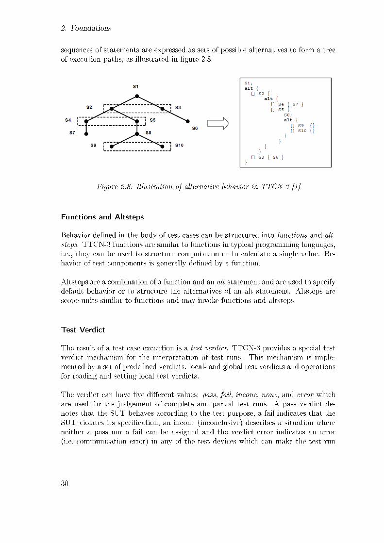
2. Foundations
sequences of statements are expressed as sets of possible alternatives to form a treeof execution paths, as illustrated in �gure 2.8.
Figure 2.8: Illustration of alternative behavior in TTCN-3 [1]
Functions and Altsteps
Behavior de�ned in the body of test cases can be structured into functions and alt-steps. TTCN-3 functions are similar to functions in typical programming languages,i.e., they can be used to structure computation or to calculate a single value. Be-havior of test components is generally de�ned by a function.
Altsteps are a combination of a function and an alt statement and are used to specifydefault behavior or to structure the alternatives of an alt statement. Altsteps arescope units similar to functions and may invoke functions and altsteps.
Test Verdict
The result of a test case execution is a test verdict. TTCN-3 provides a special testverdict mechanism for the interpretation of test runs. This mechanism is imple-mented by a set of prede�ned verdicts, local- and global test verdicts and operationsfor reading and setting local test verdicts.
The verdict can have �ve di�erent values: pass, fail, inconc, none, and error whichare used for the judgement of complete and partial test runs. A pass verdict de-notes that the SUT behaves according to the test purpose, a fail indicates that theSUT violates its speci�cation, an inconc (inconclusive) describes a situation whereneither a pass nor a fail can be assigned and the verdict error indicates an error(i.e. communication error) in any of the test devices which can make the test run
30

2.5. The Jata Test Framework
impossible to continue in a normal way. The verdict none is the initial value forlocal and global test verdicts, i.e., no other verdict has been assigned yet [25].
Each test component maintains a local verdict for tracking its own individual ver-dict. Additionally, the TTCN-3 run-time environment maintains a global test caseverdict that is updated when each test component (i.e. the MTC and each and everyPTC) terminates execution. The global test verdict, which is not accessible to testcomponents, is updated according to overwriting rules when a test component ter-minates. The �nal global test verdict is returned to the module control part whenthe test case terminates.
Figure 2.9 illustrated the relationship between test case, test components and ver-dicts [1]. Test components can communicate with each other to co-ordinate theiractions or to come to a common test verdict.
Figure 2.9: Illustration of the relationship between verdicts in TTCN-3 [1]
The concepts of TTCN-3 allow creation of powerful distributed test architectures,for example instantiations of the CTMF test methods [50]. This overview touchesonly on the most common concepts and the ones which relate to distributed testingsuch as testing for cloud applications, and the concepts Jata borrows from TTCN-3.
2.5. The Jata Test Framework
This thesis uses Jata [60], a Java test framework, in a case-study for testing a cloudapplication, described in Section 4.2.
Jata was introduced in Jata: A Language for Distributed Component Testing, by Wu,Yang and Luo [60]. It is a Java library which includes a meta-model for de�ningand structuring test cases. The meta-model uses concepts from the well known stan-dardized testing language TTCN-3, described in Section 2.4, to support distributedcomponent testing.
Jata's Java source code, binaries, and examples can be downloadedfrom: http://code.google.com/p/jata4test/
31

2. Foundations
Jata was created to address issues in test automation for distributed testing. Itsapproach is combining the strengths of two well known test frameworks: the de-facto standard unit testing framework JUnit [10] and the TTCN-3 testing language.Both are incredibly powerful, each in their own way, in specifying both simple andcomplex test cases.
2.5.1. Jata vs. JUnit
JUnit is arguably the most popular test framework for Java and has become de-facto standard for automated unit testing. It does however not focus on supportfor distributed testing. JUnit runs in its own thread space and has no means ofsupporting distributed communication back to its testing system context. In dis-tributed testing, distributed test components need a way to communicate with thetest system, as supported by TTCN-3.
Jata is not based on JUnit nor does it use any concepts from JUnit. What is commonbetween them are that both are frameworks for creating and running repeatabletests written in Java. JUnit focuses on locally executed unit testing, preferablyin isolation, while Jata focuses on distributed unit testing. In locally executedunit testing there is no need for communication between di�erent units and testdoubles [42], such as stubs or mock objects [22], are used to eliminate dependenciesbetween components.
The fundamental di�erences between the two is that JUnit does not, out of the box,support testing of distributed and parallel objects. JUnit test cases also terminatethe test execution as soon as an exception is caught while distributed tests needto �nish all threads before analyzing the results, even though an error has beendiscovered. Being a Java library it is possible to use JUnit from Jata test cases asany other Java libraries. JUnit assertions provide optionally powerful and usefulfeatures to use within Jata.
2.5.2. Jata's Meta-Model for Distributed Testing
For distributed testing a test technology that provides a systematic and structuredway of de�ning test cases is needed. With multi-threading test evaluation archi-tecture Jata promises to support complex test scenarios in a �exible manner [60].Jata's approach to distributed testing is providing rich constructs, using TTCN-3concepts, to design test cases in a systematic and structured way.
32

2.5. The Jata Test Framework
Jata's meta-model is shown in �gure 2.10. Testing concepts such as test components,alternatives, communication ports, and codecs are borrowed from TTCN-3. Jata canbe seen as a minimal implementation of TTCN-3 testing concepts for Java.
Because of the similarity to TTCN-3 this section does not go into detail on Jata'sarchitecture, the corresponding concepts are described in Section 2.4, which includesa high-level overview of TTCN-3 architecture. In the following section, 2.5.3, thecommonalities and di�erences between the two languages are described.
Figure 2.10: Jata's meta-model [60]
Usage of Jata is described in details in the case study in Section 4.2, where challengesof testing cloud applications are investigated. Jata's usability and applicability fortesting applications in cloud environments is covered in the evaluation chapter ofthe thesis (Chapter 5).
33

2. Foundations
Why Jata?
For testing distributed system within a cloud environment, TTCN-3 would be anatural option to look at. There are couple of issues however regarding usage ofTTCN-3 for research as this one. Access to appropriate tools being one and anotherbeing TTCN-3's relatively high learning curve.
Availability of tools for TTCN-3, because of licensing matters, is an issue for cloudapplications. Most TTCN-3 tools have a licensing scheme based on MAC networkaddresses, which is unfortunate for cloud research. The elastic nature of cloudsmakes it impossible to know beforehand the MAC address of the virtual machineassigned each time, making cloud research with this type of licensing model di�cult.Licensing issues are major obsticles for the cloud and need to be solved on case-by-case basis between the software vendor and the cloud provider.
The Jata language was chosen for its simplicity and promising techniques for dis-tributed systems testing based on combination of sound techniques from TTCN-3and the �exibility of it being a Java library. Licensing issues played some role in theselection, but it should be noted that a TTCN-3 tool sales representative was notcontacted for possibilities of research grant options. Early indications of Jata appli-cability returned promising results for cloud testing, and it was therefore selectedfor the research.
2.5.3. Jata and TTCN-3 Comparison
TTCN-3 is a widely recognized standard from ETSI for a testing speci�cation lan-guage. TTCN-3 tools have been developed and widely used in the industry forvarious testing purposes [25] while Jata's only usage is the authors introduction ofthe language [60].
Jata does not implement the TTCN-3 standard, rather it selects the concepts neededto implement a light-weight test framework for testing distributed systems. TTCN-3can be considered a heavyweight approach which requires commercial tool supportand relatively high learning curve. Jata only uses subset of the TTCN-3 features,and could be described as a trimmed down version of TTCN-3's core concepts. Table2.4 lists the TTCN-3 concepts that map to Jata's meta-model, shown in �gure 2.10.
As seen in the list, Jata adopts the core concepts of TTCN-3 for specifying testcases. Following sections describe how Jata uses the these TTCN-3 concepts fortest case de�nitions.
34

2.5. The Jata Test Framework
TTCN-3 ConceptTest CaseTest FunctionMain Test Component (MTC)Parallel Test Component (PTC)PortMap/Unmap portsAlt statementsAdaptersCodecs (Coders/Decoders)Verdicts
Table 2.4: Adopted TTCN-3 concepts in Jata
Test Case and Test Function
To de�ne a test case in Jata the TestCase class is inherited. The actual test casede�nition goes into the overriden Case method. The Case method has two inputparameters: the MTC and the SystemComponent. There are four things a test casegenerally needs, independent of the type of the test [42]:
1. Setup (con�gure test components and prepare the test data)
2. Exercise (stimulate the SUT)
3. Verify (evaluate the response)
4. Tear-down (close connections and take down systems if needed)
The basics of how these things are structured and implemented in a Jata test caseis borrowed from TTCN-3.
The TestFunction meta-class is used to de�ne test behaviors, as functions are usedin TTCN-3. TestFunction has an overridable method Func for the actual de�nition.The Func operation takes a test component (PTC) as a parameter which forces testengineers to create the PTC outside the function's scope.
Test Components
Jata uses the concepts of test components as is done in TTCN-3. There are aretwo types of test components in Jata: TestComponent and SystemComponent. Theformer represents MTC and PTCs which are used for sending stimulation messages
35

2. Foundations
and receiving response messages from the SUT. As in TTCN-3 the MTC is createdautomatically by the test system at the beginning of each test case execution andthe PTCs are dynamically created and stopped during the execution.
SystemComponent represents the abstract and real test system interfaces in TTCN-3 and is used by test components for communication with the SUT for sendingand receiving messages. There is exactly one SystemComponent for each Jata testsystem, but it can contain multiple system ports.
There is one major di�erence in the distribution, i.e. deployment, of parallel testcomponents between Jata and TTCN-3. In Jata it is not possible to distribute thePTCs. MTC and PTCs must run inside the same Java virtual machine. Insteadremote ports are distributed on parallel nodes of the SUT (see following section oncommunication ports).
Communication Ports
As in TTCN-3 test components contain communication ports. There are threetypes of ports de�ned in Jata: AbstractPort (AP), SystemPort (SP) and TimerPort(TP). AbstractPort owns an in�nite FIFO queue in which the incoming messagesare stored. SystemPort is composed of an AbstractPort and an Adapter. Timer-ports are used to control timeouts and are special in the way that they do no connectto other ports. An AP can map with either AP or SP, while a SP can only map withan AP. Any message passing through a port is checked against the port speci�cation,and validation exception is thrown (for the test system to handle) if the check fails.
For distributed testing SystemPorts can be distributed to remote machines, otherthan the SystemComponent runs on. Test system communication with the SUT iscontrolled through the SystemComponent's ports (local or remote). The remote im-plementation of SystemPort is one of the main feature of Jata for distributed testingsupport and is used in this thesis case-study for testing of parallel components.
Jata uses Java RMI is to connect remote ports with test system ports. Automatedport mapping in Jata is only supported within local execution context (see line 13in listing 2.2 below). Mapping remote ports with test system ports requires manualcon�guration of the mapping (e.g. with RMI client and server con�guration).
36
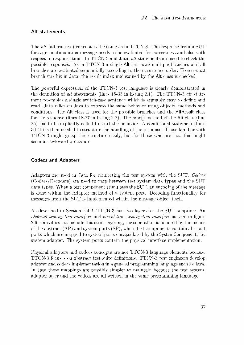
2.5. The Jata Test Framework
Alt statements
The alt (alternative) concept is the same as in TTCN-3. The response from a SUTfor a given stimulation message needs to be evaluated for correctness and also withrespect to response time. In TTCN-3 and Jata, alt statements are used to check thepossible responses. As in TTCN-3 a single Alt can have multiple branches and allbranches are evaluated sequentially according to the occurrence order. To see whatbranch was hit in Jata, the result index maintained by the Alt class is checked.
The powerful expression of the TTCN-3 test language is clearly demonstrated inthe de�nition of alt statements (lines 15-35 in listing 2.1). The TTCN-3 alt state-ment resembles a single switch-case sentence which is arguably easy to de�ne andread. Jata relies on Java to express the same behavior using objects, methods andconditions. The Alt class is used for the possible branches and the AltResult classfor the response (lines 18-27 in listing 2.2). The proc() method of the Alt class (line25) has to be explicitly called to start the behavior. A conditional statement (lines30-40) is then needed to structure the handling of the response. Those familiar withTTCN-3 might grasp this structure easily, but for those who are not, this mightseem an awkward procedure.
Codecs and Adapters
Adapters are used in Jata for connecting the test system with the SUT. Codecs(Coders/Decoders) are used to map between test system data types and the SUTdata types. When a test component stimulates the SUT, an encoding of the messageis done within the Adapter method of a system port. Decoding functionality formessages from the SUT is implemented within the message object itself.
As described in Section 2.4.2, TTCN-3 has two layers for the SUT adaption: Anabstract test system interface and a real time test system interface as seen in �gure2.6. Jata does not include this strict layering, the seperation is honored by the meansof the abstract (AP) and system ports (SP), where test components contain abstractports which are mapped to system ports encapsulated by the SystemComponent, i.e.system adapter. The system ports contain the physical interface implementation.
Physical adapters and codecs concepts are not TTCN-3 language elements becauseTTCN-3 focuses on abstract test suite de�nitions. TTCN-3 test engineers developadapter and codecs implementation in a general programming language such as Java.In Jata these mappings are possibly simpler to maintain because the test system,adapter layer and the codecs are all written in the same programming language.
37

2. Foundations
Verdicts
Jata uses the same verdict mechanism as TTCN-3. A test component maintainsthe test result as a VerdictType. The verdict types are the same as in TTCN-3 andshare the same values: pass, fail, inconc, none, and error.
Code Example
Listing 2.2 shows a typical test case written in Jata. A main entry method (line 43)is needed to start a test case. The test case itself is the Case method (line 7) whichis overridden from the Jata TestCase class.
Expected testing response is de�ned �rst (line 10). The port mapping is done withthe help of the PipeCenter class (line 13). In this case the MTC has a single ab-stract port which is mapped to a system port for a single request-response stimulus.This example does not use a remote port and the system adapter, along with itsport, runs in the same runtime context as the MTC. The stimulus is sent via theMTC port which is mapped, as previously described, to the system port (line 16).An alt statement is de�ned (lines 18-24) and then started (line 25). The result isreceived (line 27) and handled based on de�ned branches of the alt statement (lines30-40). If the expected response was received the MTC is indicated so, by a callto its Pass() method (line 31). Jata does not provide test runners as JUnit, otherthan textual logging, so the test verdict is written out at the end of the test (line 46).
1 public class MyTestCase extends TestCase<AbsComp , SysComp> {2 public MyTestCase ( ) throws JataTestCaseException {3 super (AbsComp . class , SysComp . class ) ;4 }56 @Override7 protected void Case (AbsComp mtc , SysComp sys )8 throws JataException {9 // The expec ted response10 St r ing expectedResponse = "42" ;1112 // Map por t s between MTC and SUT ( system component )13 PipeCenter .Map(mtc . abstractPort , sys . systemPort ) ;1415 // Send the s t imu lu s v ia MTC' s por t16 mtc . abs t rac tPor t . send (new QueryMsg ( "Meaning o f l i f e ?" ) ) ;1718 Alt alt = new Alt ( ) ;19 Timer t = new Timer ( ) ;20 t . start ( ) ;21
38

2.5. The Jata Test Framework
22 alt . addBranch (mtc . abstractPort ,23 new ResponseMsg ( expectedResponse ) ) ;24 alt . addBranch ( t , new SetTimeMessage (100) ) ;25 alt . proc ( ) ;2627 AltResu l t r e s u l t = alt . g e tResu l t ( ) ;2829 // Handle the case f o r an expec ted answer .30 i f ( r e s u l t . index == 0) {31 mtc . Pass ( ) ;32 }33 // Handle t imeout34 else i f ( r e s u l t . index == 1) {35 mtc . Fa i l ( ) ;36 }37 // Handle any o ther message38 else {39 mtc . Fa i l ( ) ;40 }41 }4243 public stat ic void main ( St r ing [ ] argv ) throws JataException {44 MyTestCase myTestCase = new MyTestCase ( ) ;45 myTestCase . start ( ) ;46 System . out . p r i n t l n ( "MyTestCase r e s u l t : " +47 myTestCase . ge tVerd i c t ( ) ) ;48 }49 }
Listing 2.2: Jata typical test case structure
Compared to the TTCN-3 code example in listing 2.1 the two structures are verysimilar and shows that Jata tries to mimic TTCN-3, as much as it can, in test casestructuring.
39


3. Related Work
This chapter describes the related work where software testing meets cloud comput-ing. It is worth noting that because of the recent introduction of cloud computing,software testing researches are generally lacking for the �eld.
To get an overview of the importance of the research topic, and the availabilityof literature, table 3.1 shows the number of articles found by searching for for thekeywords �Cloud-Computing� and �Software-Testing� in the literature search enginesGoogle scholar and LibHub1.
Year LibHub Google scholar2010 22 972009 4 262008 3 92007 0 1
Table 3.1: Literature search results
No evaluation is made here on the relevance of the results returned, i.e. how relevanteach result is to both cloud computing and software testing. Of the 97 resultsreturned by Google scholar only very few relate to testing of cloud applicationsor within the cloud. It can in fact be stated that research is lacking in the areaof software testing for clouds, especially for testing of the cloud. The numbersindicate however that in the last years these concepts together have been receivingmore attention from academic researchers. This goes hand in hand with Google'strend results on search trends for Cloud-Computing's rising popularity as seen in�gure 3.1.
The upper section of the diagram shows search volume index for the two terms andthe lower for news reference volume. The blue line shows search trends for softwaretesting while the red one shows clearly the rising trend of cloud computing. Softwaretesting does not show up on the news reference volume while the news chart-line forcloud computing bears signs of hype in the commercial community. The �ags on
1SemperTool's LibHub is Lund University search tool to discover and access the institution'ssubscribed to and recommended information resources.
41

3. Related Work
Figure 3.1: Google trends diagram [57]
the cloud computing search chart-line, marked A-E, are links between certain newsitems and changes in the graph, which is a special feature for trend analysis.
For an overview of related work in the �eld of software testing for cloud computing,the work is grouped into the three categories of STITC (see Section 2.3.5). Thescope of this thesis is testing of the cloud, with related work discussed in Section3.2.
3.1. Testing in the Cloud
Most of the current related work for software testing and cloud computing focuseson testing in the cloud, e.g. for con�guration testing and load testing.
YETI on the Cloud, by Oriol and Ullah [44] discusses and proposes a testing toolfor distributing software testing over multiple computers in a cloud, for performancegain in running the tests. YETI (York Extensible Testing Infrastructure)2 is an auto-mated random testing tool for Java applications. A YETI testing session consists ofa sequence of calls made to methods at random using random generated arguments(�monkey crash test�). Oriol's and Ullah's paper presents cloud-enabled version ofYETI which relies on on map/reduce implementation of Apache Hadoop3 to dis-tribute the testing sessions on remote machines and recombine them at the end ofthe test.
In Cloud-based Performance Testing of Network Management Systems, by Ganon
2YETI. http://yeti.origo.ethz.ch/3Hadoop. http://hadoop.apache.org/
42

3.2. Testing of the Cloud
and Zilbershtein [23], a method for performance testing of network managementsystems (NMS) is presented by a case study where a NMS was tested using commer-cial cloud computing services (Amazon EC2). The case study involved instantiationof large numbers of virtual network elements in a cloud infrastructure, to simulatelarge scale networks for NMS testing purposes. After the network of virtual elementsis up, it is used for performance testing of the NMS. They used cloud infrastruc-ture instead of running a simulator or other infrastructure stating that the cloudinfrastructure provides less expensive and more scalable implementation.
Cloud9 [13, 16, 18] is a platform for automatic testing which parallelizes symbolicexecution, an e�ective, but still poorly scalable test automation technique to cloudinfrastructures. Currently supported platforms are Amazon EC2 and Eucalyptus.Symbolic execution tries to eliminate the need for humans in selecting test inputs,but the method faces many challenges, such as it is requires an �expensive� codebranch search algorithm. Symbolic execution algorithms require high memory con-sumption and are CPU-intensive, both of which are roughly exponential in programsize. The aim of Cloud9 is to overcome these challenges and o�er symbolic testingtechniques as an easily accessible web service. By using large clusters of cloud in-stances, the plan is to make this automated test case technique viable and practicalfor software testing. Cloud9's service cost is proportional to the size of the SUT.The pricing model is based on charges according to test goal speci�cations that usersprovide.
D-Cloud [8, 28, 29] is an example of work that can fall either in category of testingin the cloud, or of the cloud. It enables automation of system con�guration andthe ability to run test cases simultaneously, which places the framework in thiscategory of testing in the cloud. The framework has also the ability to emulatehardware faults which can put it in the category testing of cloud applications, i.e.how applications respond to and handle hardware failures. Eucalyptus is D-Cloud'ssupported cloud management framework.
3.2. Testing of the Cloud
The focus of this thesis is testing of the cloud. Little work for testing of cloudapplication has been published. Chan, Mei and Zhang [17] discuss testing of cloudapplications and propose testing criteria based on modeling of cloud applications.One criterion is de�ned to test whether cloud application performs correctly af-ter horizontal scaling of the cloud, and addresses the problem that the number ofpossible scaling ways are potentially in�nite, and thus, infeasible to test every con-�guration. Horizontal scaling, also known as scaling out, is adding more machines,generally inexpensive commodity hardware, to the environment. Cloud computing
43

3. Related Work
strengths lie to a large degree in the concept of horizontal scaling. Vertical scaling,also known as scaling up, in contrast means adding more hardware resources to thesame machine, generally by adding more processors and memory.
Various studies have been made for testing distributed systems. In Distributed UnitTesting [54], by Runtao et al., the authors introduce the DisUnit framework to ad-dress challenges of distributed testing. Issues such as synchronization, complex con-�gurations, and test result management. Synchronization is one important aspectin distributed testing and a time-out feature was not included in previous versionof JUnit, which DisUnit solves. The DisUnit framework is used to control testingby automatically setting up remote machines, running test-cases and shutting downthe servers. DisUnit also removes the con�guration information from the test code,which permits the test to run in di�erent environments and con�gurations withouthaving to edit the code, making DisUnit valuable for con�guration testing.
DisUnit's testing architecture is based on what is described as in-container test-ing [40]. With in-container testing the test cases run within the same context asthe run-time container for the SUT, for instance a web server or application server.Jakarta Cactus4 is an example of in-container test framework for Java Servlets, En-terprise Java Beans and Java Tag libraries. By running the test cases within thesame runtime context as the components under test, the test cases have access tosemantic features like con�guration �les and available services which are valuablefor the test. DisUnit currently supports in-container testing for Java HORB5 andCORBA applications. Detailed information on DisUnit's architecture and commu-nication between the distributed testing components is however missing making itdi�cult to argue about the solution for distributed testing. The downloadable ver-sion of the framework as promised by the paper is also missing.
Cloud computing has evolved from grid computing technologies. Some research hasbeen done on the testing of grid computing applications. Rings, Neukirchen andGrabowski [50] use TTCN-3 for testing of a grid application, in particular testingwork-�ow of grid applications.
This thesis is largely inspired by the grid testing methods introduced by Rings,Neukirchen and Grabowski [49, 50]. Instead of using TTCN-3 in a grid environmentthis thesis investigates cloud testing challenges with the support of the Jata testframework [60]. Jata uses TTCN-3 the concepts and therefore it is possible to usetesting architecture ideas from the previous grid work. The focus of the previouswork testing was on testing of the distribution management aspects of the SUT asis also done in this thesis.
4Jakarta Cactus. http://jakarta.apache.org/cactus/5HORB. DisUnit author's middleware for distributed Java ORB applications
44

3.3. Migrating Testing to the cloud
Jata combines the test case structure of JUnit and testing concepts of TTCN-3. Itsinitial version and research ideas were published recently and it has only been usedby the authors in a case study for web services functional testing [60]. Usage of Jatafor testing parallel functionality of distributed systems or systems within cloud en-vironment, as is done in the case study of this thesis, has not been addressed before.TTCN-3 and Jata are described in foundation sections 2.4 and 2.5 respectively.
3.3. Migrating Testing to the cloud
This category contains ideas of testing as a service provided by the cloud vendor,or other third party provider. The concept involves moving the testing process, testassets, and test infrastructure from on-premises to the cloud.
In the cloud world it is common to name services in the style of X-as-a-Service.Various work has been done in the �eld of Software-Testing-as-a-Service (STaaS).The service was de�ned by Leo van der Aalst as:
Software Testing as a Service (STaaS) is a model of software testing usedto test an application as a service provided to customers across the In-ternet. By eliminating the need to test the application on the customer'sown computer with testers on site, STaaS alleviates the customer's bur-den of installing and maintaining test environments, sourcing and (test)support. Using STaaS can also reduce the costs of testing, through lesscostly, on-demand pricing. [2]
With STaaS the cloud can decrease costs for testing activities. Section 2.3.6 de-scribed an example of test-lab for cost reduction related to resources needed fordi�erent testing activities. STaaS takes that model even further in the way thatnot only hardware is scaled on-demand but also the testing software and even testengineers. The idea can be seen as test service outsourcing where test machines,test software and, possibly test engineers are outsourced.
When to Migrate Software Testing to the Cloud?, by Parveen and Tilley [45], waspresented at the 2010 Software Testing in the Cloud (STITC) conference. The paperdiscusses what variables a�ect decisions in migrating testing to the cloud. Accordingto the authors the decision should be made by viewing the matter from two per-spectives: the characteristics of an application under test, and the types of testingperformed on the application. Characteristics to consider are test case independence,the operational environment (test bed) and the ability of an application's interfaceto be tested against, i.e. does it have an API or only graphical user interface. Theyconclude that the types of testing to be appropriate for testing in the cloud are unit
45

3. Related Work
testing, high volume automated testing (HVTA), and performance testing.
Riungu et al. did a qualitative study [51] to identify research issues for softwaretesting in cloud computing, where interviews were conducted with managers fromdi�erent organizations. The motivation for the work was the fact that little hadbeen written about the topic before and academic research in the area is scarce.The research aim was to explore and understand the conditions that in�uence soft-ware testing as an on-line service in order to point out research issues for softwaretesting in the cloud. The discussion with the managers took into account the prosand cons of using the cloud for various test services. They categorized their issue�ndings according to application issues, management issues, and legal- and �nancialissues. The authors claim that by addressing the issues listed under the categories,researchers should be able to o�er reliable recommendation for practitioners in theindustry.
Riungu et al. made an earlier study [52] were they acknowledged that cloud com-puting was going to be a central platform for on-line testing and service deliveryand also listed various research issues.
Cloud9, D-Cloud, and YETI on the cloud, which were covered in Section 3.1, can beconsidered as an examples of STaaS services that have already available in the cloud.Examples of commercial services are Sauce onDemand6 and UTest7. Sauce OnDe-mand is based on Selenium8 web testing system, that enables web applications tobe tested by multiple browsers running in the cloud. Through UTest, test engineersare available on-demand which provides software testing solutions to its customersthrough access to professional testers community. Large available communities likeUTest have been described as crowd-sourcing [30].
Another testing service in the cloud is Test-Support-as-a-Service (TSaaS), and isdescribed by King and Ganti in Migrating Autonomic Self-Testing to the Cloud [38].Autonomic self-testing (AST) and TSaaS make use of the processing capabilitiesprovided by the cloud to improve self-testing processes. TSaas provides cloud cus-tomers automated test operations (setup, assertion, and tear-down) for remotelyhosted cloud services. The cloud vendors provide the self-test harness for monitor-ing and validating dynamic adaptations and updates to their hosted services, withthe help of AST, where test managers are deployed throughout the cloud to validatedynamic adaptations and updates of cloud instances.
6Sauce OnDemand. http://saucelabs.com/ondemand7UTest. http://www.utest.com/8Selenium. http://seleniumhq.org/
46

4. Testing Cloud Applications
In this chapter a case study for integration testing a distributed system within cloudenviroment is described.
Section 4.1 contains an overview of the Sun�ow rendering system that is used as thesystem under test for the case study, including a description on how Sun�ow wasadapted to run within a cloud environment. Section 4.2 introduces the testing forthe distributed rendering application in the cloud. In section 4.3 the test case designand in section 4.4 the Jata test case speci�cation for the case study are described indetail. Finally in section 4.5, the procedure of setting up and running the test bedis described.
4.1. Cloud Application Under Test
This section describes the cloud application that is used as the system under test(SUT) for the case study in this thesis. Sun�ow, multi processing image renderingapplication, was selected as the application under test for its parallel functionality.
Sun�ow is an open source rendering system for photo-realistic imagesynthesis. It is written in Java and built around a �exible ray tracingcore and an extensible object-oriented design.1
The reason for using parallelization and concurrent computing application is toexplore to the full, with advanced testing techniques, the challenges proposed intesting distributed systems within a cloud environment.
Image rendering is an extremely time consuming computing task, therefore renderingsystems like Sun�ow have been created to split up the task into smaller subtasks forparallel computing. For a typical rendering job, one master node is needed for theapplication management and several worker nodes for solving individual renderingtasks.
1Sun�ow. http://sun�ow.sourceforge.net/
47

4. Testing Cloud Applications
The control part or the distribution management of the application is thereforea good candidate for testing within a cloud environment. One cloud instance isneeded for the master node and an arbitrary number of other instances for theworkers, where the focus of the testing is on the communication of the distributedcomponents involved.
4.1.1. Image Rendering
Image rendering is the process of generating an image from a model which is de�nedin a scene �le. A scene �le contains information necessary for the rendering such asgeometry, viewpoint, texture, lighting and shading. Figure 4.1 shows a 3D view ofa model (scene) before any rendering has been done, whereas �gure 4.2 shows therendered image result.
Figure 4.1: 3D view af a scene [39] Figure 4.2: Rendering results [39]
An image rendering job is split into buckets of smaller tasks. Each bucket representa part of the image. The working threads for rendering a bucket is called a worker.In the cloud computing environment each worker runs on a dedicated cloud instance.
4.1.2. Cloud Support for Sun�ow
Sun�ow's work distribution algorithm distributes the workload for parallel process-ing to multiple CPU cores on a single computer. The system has however beenadapted to run on both grid and cloud platforms. Ragnar Skulason, fellow studentat the Faculty of Industrial Engineering, Mechanical Engineering and Computer Sci-ence at the University of Iceland2, adapted Sun�ow to run on Amazon EC2, for hisMasters thesis research Architectural Operations in Cloud Computing [55].
2University of Iceland. http://www.hi.is/en/introduction
48
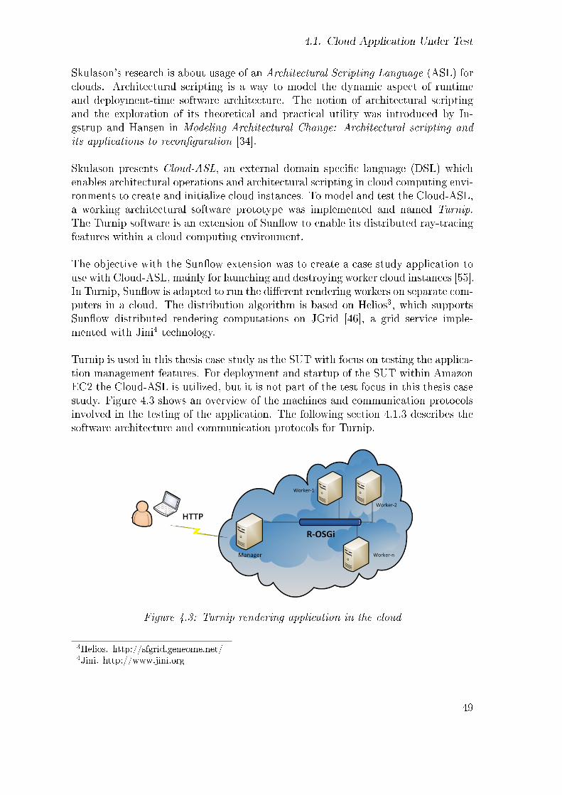
4.1. Cloud Application Under Test
Skulason's research is about usage of an Architectural Scripting Language (ASL) forclouds. Architectural scripting is a way to model the dynamic aspect of runtimeand deployment-time software architecture. The notion of architectural scriptingand the exploration of its theoretical and practical utility was introduced by In-gstrup and Hansen in Modeling Architectural Change: Architectural scripting andits applications to recon�guration [34].
Skulason presents Cloud-ASL, an external domain speci�c language (DSL) whichenables architectural operations and architectural scripting in cloud computing envi-ronments to create and initialize cloud instances. To model and test the Cloud-ASL,a working architectural software prototype was implemented and named Turnip.The Turnip software is an extension of Sun�ow to enable its distributed ray-tracingfeatures within a cloud computing environment.
The objective with the Sun�ow extension was to create a case study application touse with Cloud-ASL, mainly for launching and destroying worker cloud instances [55].In Turnip, Sun�ow is adapted to run the di�erent rendering workers on separate com-puters in a cloud. The distribution algorithm is based on Helios3, which supportsSun�ow distributed rendering computations on JGrid [46], a grid service imple-mented with Jini4 technology.
Turnip is used in this thesis case study as the SUT with focus on testing the applica-tion management features. For deployment and startup of the SUT within AmazonEC2 the Cloud-ASL is utilized, but it is not part of the test focus in this thesis casestudy. Figure 4.3 shows an overview of the machines and communication protocolsinvolved in the testing of the application. The following section 4.1.3 describes thesoftware architecture and communication protocols for Turnip.
Figure 4.3: Turnip rendering application in the cloud
3Helios. http://sfgrid.geneome.net/4Jini. http://www.jini.org
49

4. Testing Cloud Applications
4.1.3. Turnip Rendering Application for the Cloud
The Turnip application includes a web management console. Figure 4.4 shows theconsole when an image rendering is in process. The scene �le behind this particularrendering uses 300 buckets to complete the job. In the partially rendered imageroughly 100 buckets have been rendered resulting in 30% of the �nal image.
Figure 4.4: Turnip web management console
The left hand side of the console contains the actions menu. The Turnip consoleprovides only the basic functionality needed to render images. Available actions are'add worker', 'register worker', 'submit work', and 'display log'. In this prototypeversion of Turnip, the console provides no means of selecting what scene �le shouldbe rendered. The �le needs to be uploaded to the server manually. Below the actionsmenu is the list of workers, IP addresses, in use.
A typical scenario for the full life-cycle of a rendering job is following:
1. Start Turnip web application on a cloud machine
2. Add 1..n workers
3. Submit work (start rendering)
The actual rendering job (i.e. the image result) is not the focus of the testing.Rather it is the application management behind a rendering job that is the focus of
50
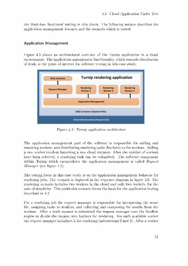
4.1. Cloud Application Under Test
the black-box functional testing in this thesis. The following section describes theapplication management features and the scenario which is tested.
Application Management
Figure 4.5 shows an architectural overview of the Turnip application in a cloudenvironment. The application management functionality, which controls distributionof work, is the point of interest for software testing in this case study.
Figure 4.5: Turnip application architecture
The application management part of the software is responsible for adding andremoving workers, and distributing rendering tasks (buckets) to the workers. Addinga new worker involves launching a new cloud instance. After the number of workershave been selected, a rendering task can be submitted. The software componentwithin Turnip which encapsulates the application management is called RequestManager (see �gure 4.5).
The testing focus in this case study is on the application management behavior forrendering jobs. The scenario is depicted in the sequence diagram in �gure 4.6. Therendering scenario includes two workers in the cloud and only two buckets, for thesake of simplicity. This particular scenario forms the basis for the application testingdescribed in 4.2.
For a rendering job the request manager is responsible for interpreting the scene�le, assigning tasks to workers, and collecting and composing the results from theworkers. After a work request is submitted the request manager uses the Sun�owengine to divide the request into buckets for rendering. For each available workerthe request manager initializes it for rendering (interactions 2 and 3). After a worker
51

4. Testing Cloud Applications
Figure 4.6: Rendering job scenario
is initialized it asks for the next bucket for rendering (interactions 4 and 5). Theworker is returned task information about the bucket from the request manager,which the worker uses for partial rendering of the image. After a worker �nishes atask it sends an image part result back to the request manager (interactions 6 and8), which is merged into the partial result image. The continuously changing imageis repeatedly written to a �le directory on the server, where it is available for theweb interface (interaction 7).
The result, partial and �nal, is presented in the Turnip web management interface,by periodically polling the working image, using AJAX (Asynchronous JavaScriptand XML) features. Once all tasks are completed, the whole image is availablein the web interface and that fact is indicated with a �nished progress bar status(interaction 9).
Software Architecture
The application software architecture in�uences the testing strategies described insection 4.2. Figure 4.7 contains an UML deployment diagram for the Turnip appli-
52
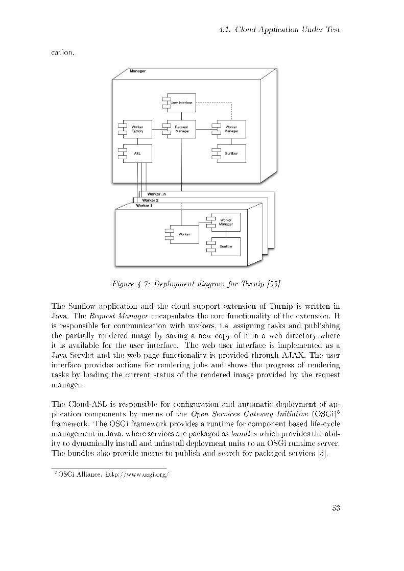
4.1. Cloud Application Under Test
cation.
Figure 4.7: Deployment diagram for Turnip [55]
The Sun�ow application and the cloud support extension of Turnip is written inJava. The Request Manager encapsulates the core functionality of the extension. Itis responsible for communication with workers, i.e. assigning tasks and publishingthe partially rendered image by saving a new copy of it in a web directory whereit is available for the user interface. The web user interface is implemented as aJava Servlet and the web page functionality is provided through AJAX. The userinterface provides actions for rendering jobs and shows the progress of renderingtasks by loading the current status of the rendered image provided by the requestmanager.
The Cloud-ASL is responsible for con�guration and automatic deployment of ap-plication components by means of the Open Services Gateway Initiative (OSGi)5
framework. The OSGi framework provides a runtime for component based life-cyclemanagement in Java, where services are packaged as bundles which provides the abil-ity to dynamically install and uninstall deployment units to an OSGi runtime server.The bundles also provide means to publish and search for packaged services [3].
5OSGi Alliance. http://www.osgi.org/
53

4. Testing Cloud Applications
The manager and workers are deployed as OSGi services and the communicationbetween manager and workers is via remote OSGi (R-OSGi). The workers arecreated by the Cloud-ASL, which uses SSH and Telnet to access the OSGi remoteshell on the cloud instances. TheWorker Factory andWorker Manager componentsencapsulate the OSGi communication for creating and launching workers within thecloud. The manager bundle and the worker bundles include their own copy of theSun�ow Java library.
4.1.4. Amazon Machine Image
The AMI created by Skulason [55] used for this case study is public with ID ami-4552bb2c in Amazon's instance store. The same image is used both for the managerand worker machines. The runtime software installed on the AMI is listed in table4.1.
Runtime Version DescriptionOperating System 32 bit Ubuntu 9.10 Commercially sponsored Debian-
derived Linux distribution.Java runtime OpenJDK 1.6 Open source implementation of
Java SE 6OSGi runtime Apache Felix 3.2.0 OSGi R4 Service Platform for
OSGi bundlesHTTP container Jetty (Eclipse/Codehaus) Included in the Felix distribution
Table 4.1: Run-time software for the case study application
The AMI includes the necessary runtimes for the Turnip rendering application, withUbuntu Linux as the operating system and Java SE 6 installed. Apache Felix is usedas the OSGi service platform, which includes the Jetty6 web application server.
Note that the Turnip application binaries are not part of the image, because theyare installed with Cloud-ASL features after the cloud instance has been launched.
6Jetty. http://www.eclipse.org/jetty/
54

4.2. Test Plan
4.2. Test Plan
The structure of this section is based on concepts from the Test Plan chapter ofthe IEEE Standard for Software and System Test Documentation (IEEE Std 829-2008) [32]. The standard is introduced in section 2.3.7 on test documentation. Thissection and the following describe the test plan, the test design, and the test casespeci�cation for a distributed image rendering application running in the AmazonEC2 cloud environment. Jata was described in section 2.5 and the applicationfeatures were described in section 4.1.
Following the test plan in this section the test design is covered in section 4.3 whereasthe test case speci�cation is covered in 4.4. A brief description of the test procedureis in section 4.5. Note that the IEEE format is only used as basis for the structureof this thesis text. The following sections might omit details that are not relevantto the research purpose of this thesis, but might be needed in a conventional testdocumentation. The thesis also adds information to support the thesis work, suchas source code listings, as is normally not done in a conventional software testdocumentation.
4.2.1. Introduction
The aim of this case study is to point out the challenges and obstacles in testingapplications running in elastic cloud environment. Another objective is to evaluateJata's applicability for the task. The focus is on software testing for cloud appli-cation. The Turnip application [55], a cloud extension of Sun�ow rendering systemadapted for Amazon EC2, is used as the system under test. The application is aparallel computing application that provides means for advanced software testingtechniques.
As opposed to 'real world' software testing the objective is not to reveal defects inthe application itself or the cloud service platform it runs on. Rather the objectivesare to reveal issues for software testing within cloud environment, and to evaluateJata for testing advanced cloud application functionality.
Figure 4.8 shows a high level overview of the components within the distributedsystem under test. The main program, i.e. the application management, is the focusof the test. It distributes rendering tasks to workers for rendering small parts of the�nal image which is the output from the application. A common and straightforwardway of testing is by unit testing and system testing. Those levels are depicted,however they are not the focus of this thesis.
55

4. Testing Cloud Applications
Figure 4.8: Application components
With system testing the whole application is used and the actual output is tested.System testing would verify that the correct image output is created by composingall partial images of the rendering tasks. In unit testing each worker, i.e. the partialimage rendering algorithm, is tested in isolation.
The objective in this case study is testing the distribution algorithm with integrationtechniques. Figure 4.9 shows how test components are added to the test bed forintegration and communication testing. Following sections describes the integrationtesting method.
4.2.2. Test items
The application management, i.e. the Request Manager in �gure 4.7, is the itemto be tested. The request manager, which provides the core functionality of theTurnip application, takes orders from the user interface to add workers or to starta rendering job. It uses the Sun�ow engine to split jobs into tasks and delegate toworkers. Finally it composes the �nal image out of all the image parts received backfrom the workers.
Figure 4.9 shows how integration testing is enabled by installing test componentsat each worker. A main test component (MTC) controls the stimulation and ver-i�cation of the application behavior. Actual rendering does not take place, ratherdummy image parts are returned from the parallel test components.
56

4.2. Test Plan
Figure 4.9: Integration testing of application components
4.2.3. Features to be tested
The testing focuses on the application management, i.e. the communication withworkers and the distribution of rendering tasks in order to verify that testing can beperformed within a cloud computing environment. The integration between the webinterface layer and the request manager is also under test. The testing is done bysimulating an HTTP request to the web layer which needs to interpret the requestcorrectly in order to start the application management. The rendering scenariowhich forms the basis of the testing is shown in �gure 4.6.
Application output testing is done in the way that a �dummy� non-rendered imageis assembled and veri�ed. The dummy image does not represent the input scene �leinformation. The application management uses the scene �le however in deciding thenumber of buckets (tasks) needed for the job. The input scene �le used requires 300rendering tasks to be handled resulting in 300 image parts. The disk �le size of thecomposed dummy image is veri�ed in a simple manner to make sure all parallel testcomponents have been issued the precise number of rendering tasks and returneddummy image parts accordingly.
57

4. Testing Cloud Applications
4.2.4. Features not to be tested
The testing assumes that Amazon EC2 is adequately tested and that failures donot relate to the cloud service platform, but only to the cloud application, i.e. thedistribution management aspects of the application. Testing the cloud middlewareis therefore not within the scope of this thesis. The Cloud-ASL features of Turnipare also not within the scope of testing.
As stated earlier real output generation is not tested, which would be done with asystem testing approach. Besides real output generation veri�cation the performanceof rendering might be of special interest from a user perspective.
It would be possible to utilize Jata for output veri�cation and performance testing.Verifying the output is made in the case study for a composed dummy image. AJata test case for output veri�cation would be simple in the sense that it does notrequire parallel testing components.
4.2.5. Approach
The testing approach is a black-box functional integration testing, which is imple-mented with the Jata test framework. The Jata test architecture uses multi-partytesting concepts from CTMF and TTCN-3.
4.2.6. Item pass/fail criteria
The pass/fail criteria is based on the scene �le input for the rendering task. Forthe application management features the testing veri�es that all available nodes areutilized for task submissions. Furthermore, based on the scene �le, if 300 bucketsshould be rendered, the test fails if not exactly 300 buckets are rendered. For outputevaluation, the �le size of the resulting image is veri�ed for correctness.
4.2.7. Test environment
The application under test was described in section 4.1. This section describes thesoftware and hardware used in the case study test bed.
Eucalyptus was considered as a runtime cloud provider for this thesis case study.
58

4.2. Test Plan
However when starting the work, access to an Eucalyptus private cloud was not athand. What favored the Amazon EC2 was the availability of distributed applicationsource code and knowledge in our research group at the university [55]. Otherreasons include EC2's easy accessibility, inexpensiveness, and good software APIand documentation support.
Software Speci�cation
The runtime software used for the SUT is installed on Amazon Machine Image idami-4552bb2c, and was described in section 4.1.
Cloud-ASL features are used to launch the AMI within the Amazon EC2 cloudand install the Turnip application on the machine. That node is referred to as theapplication's 'manager' node.
The Turnip version has not been labeled but it is the latest version from the workof Skulason [55]. The Amazon EC2 used is the current (May 2011) on-line cloudservice version. The Jata framework used for testing and is considered for evaluationis version 0.1, downloaded from http://code.google.com/p/jata4test/.
Hardware Speci�cation
The hardware used for the case study is speci�ed by the cloud instance type con�g-uration. The case study used the Amazon EC2 standard 'Small' instance type withthe attributes listed in table 4.2.
Type RAM CPUs Instance I/O Price/(GB) (EC2) Storage Platform Perform. hour
Small 1.7 1 160 GB 32-bit Moderate $0.095
Table 4.2: Amazon 'Small' instance type (May 7, 2011)
Figure 4.10 shows the test bed for the case study. The test bed consists of four cloudinstances and one test engineer machine for control and monitoring purposes. Thefour cloud machines roles are following:
• Instance 1: The test system (Jata)
• Instance 2: The Turnip master node
• Instance 3: Turnip rendering worker 1
• Instance 4: Turnip rendering worker 2
59

4. Testing Cloud Applications
Figure 4.10: The test bed
The test bed �gure includes communication protocols used in the testing. Thetest engineer uses SSH (Secure Shell) to communicate with the Jata test systemmachine, which runs in the cloud for simpler �rewall con�guration reasons. TheJata test components use Java RMI (Remote Method Invocation) for exchangingmessages. RMI needs special security con�guration for the cloud if participantsare needed to run outside the cloud. Another argument in favor of including thetest system machine within the cloud is that it improves performance of test caseexecution, because of the geographical location of involved instances.
The test system stimulates the SUT via HTTP through the application web inter-face. The SUT services are packaged and deployed as OSGi bundles and internalapplication communication uses the Remote-OSGi (R-OSGi) protocol.
4.3. Test Design
The following sections are structured using concepts from the Test Design Speci-�cation chapter of the IEEE Standard for Software and System Test Documenta-tion [32].
4.3.1. Conceptual Test Architecture
The multi-party test architecture from the Conformance Testing Methodology andFramework (CTMF) is used for testing the parallel application management func-
60
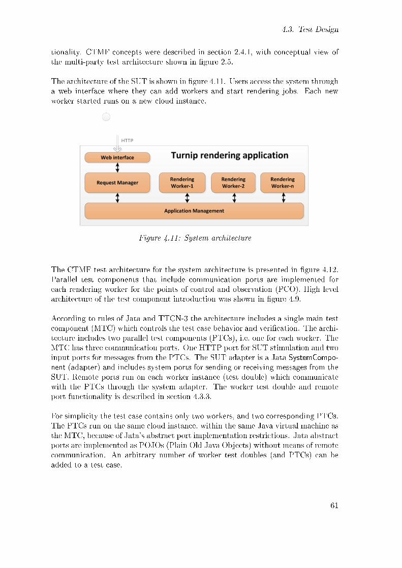
4.3. Test Design
tionality. CTMF concepts were described in section 2.4.1, with conceptual view ofthe multi-party test architecture shown in �gure 2.5.
The architecture of the SUT is shown in �gure 4.11. Users access the system througha web interface where they can add workers and start rendering jobs. Each newworker started runs on a new cloud instance.
Figure 4.11: System architecture
The CTMF test architecture for the system architecture is presented in �gure 4.12.Parallel test components that include communication ports are implemented foreach rendering worker for the points of control and observation (PCO). High levelarchitecture of the test component introduction was shown in �gure 4.9.
According to rules of Jata and TTCN-3 the architecture includes a single main testcomponent (MTC) which controls the test case behavior and veri�cation. The archi-tecture includes two parallel test components (PTCs), i.e. one for each worker. TheMTC has three communication ports. One HTTP port for SUT stimulation and twoinput ports for messages from the PTCs. The SUT adapter is a Jata SystemCompo-nent (adapter) and includes system ports for sending or receiving messages from theSUT. Remote ports run on each worker instance (test double) which communicatewith the PTCs through the system adapter. The worker test double and remoteport functionality is described in section 4.3.3.
For simplicity the test case contains only two workers, and two corresponding PTCs.The PTCs run on the same cloud instance, within the same Java virtual machine asthe MTC, because of Jata's abstract port implementation restrictions. Jata abstractports are implemented as POJOs (Plain Old Java Objects) without means of remotecommunication. An arbitrary number of worker test doubles (and PTCs) can beadded to a test case.
61

4. Testing Cloud Applications
Figure 4.12: Detailed test architecture
A detailed description of the test components and their behavior is in the followingsection on the features to be tested.
4.3.2. Features to be Tested - Conceptual Test Scenario
The behaviour of the application management under test was depicted in the se-quence diagram in �gure 4.6. A conceptual view of the testing procedure is visualizedin the sequence diagram in �gure 4.13.
The interaction sequence is identical between the actual application rendering sce-nario and the test architecture scenario. The di�erence is that test componentshave been introduced to simulate both user behavior and bucket rendering in thearchitecture to control the interactions. Instead of a user (web-browser) an MTCis implemented to control stimulation and veri�cation. The rendering workers have
62

4.3. Test Design
Figure 4.13: Conceptual test sequence diagram
been replaced by PTCs with communication ports to receive and send informationintended for the workers. The MTC starts the test case by sending 'rendering job'stimulus (interaction 1). The SUT, application management part, who thinks it isannouncing real workers to start rendering is actually calling PTCs (interactions 2and 3). The PTCs ask for the next bucket to render as would be expected froma worker (interactions 4 and 5). When a PTC receives the bucket information itsends it to the MTC (interactions 6 and 8), which collects all knowledge about ren-dering tasks for veri�cation. The PTC creates a dummy image to send back to theapplication management as is expected from rendering tasks (interaction 7 and 9).Finally when the MTC has received all expected bucket information it downloadsthe composed image result from the SUT (interaction 10). The MTC veri�es thenumber of messages it received from the PTCs and the �le size of the composeddummy image.
To implement this behavior the PTCs need to be deployed on the worker instancemachines which is unfortunately not supported by Jata. The following section 4.3.3describes a workaround with the help of a Test Double. Section 4.3.4 shows how theconceptual test architecture is implemented with the help of the test double.
63

4. Testing Cloud Applications
4.3.3. Concrete Test Architecture Using Worker Test Double
In principle it is preferred to deploy the PTCs on the worker instances, which isunfortunately not easy to achieve with Jata. To solve this issue a Test Double isintroduced. Test doubles are a group of testing objects such as: stubs, mock objects,and fake objects, as described by Meszaros [42].
The reason for having a test double implementation for the worker component in-stead of an actual PTC installed on the worker instance is that in the Jata environ-ment PTCs are not able to run on remote machines like the case is with TTCN-3.Instead remote ports need to be located at the remote machines. The test doubleencapsulates Jata remote port functionality for workers.
The worker OSGi service was therefore switched out for a test double. The wholeOSGi service for the worker is replaced by a Java component that implements theJava interface for the worker service. In the OSGi service descriptor �le the testdouble is con�gured to be used instead of the real one. That way the test doublescan be started with the same methods as real workers are started, i.e. through theweb interface command. Starting test doubles is not done within the test case itself.It can be done in a test setup script or through a test UI utility made for this casestudy. The test procedure details are covered in section 4.5.
This variation of a test double can be considered a stub that forwards renderinginformation received by the worker to the test system. The stub is implementedto support the remote port functionality in Jata, for forwarding information aboutbuckets to a corresponding PTC. The test double is also responsible for sending fakeimage parts back to the request manager, without the need of Sun�ow. Instead ofusing the Sun�ow engine for rendering tasks, the test double sends information aboutbuckets directly to the PTC through a remote port. With test double architectureit is easy to factor out the usage of Sun�ow. Figure 4.14 depicts the functionalityand behavior of the test double worker in a partial view of the test system. Notethat in the picture the Jata SystemComponent (adapter) is omitted for simplicityand the communication between the test double remote port and the PTC is showndirectly.
It would be preferred testing technique that the PTC would create the image partbased on bucket information and send it to the SUT, instead of making it theworker's test double responsibility. There are however some di�culties with thatapproach. The request manager expects a remote OSGi call back with the imagepart, and the OSGi platform does not allow remote OSGi communication from non-OSGi application. Remote OSGi method invocations can only be made from withina OSGi container. The Jata test system runs as a standalone Java application andcan not communicate via OSGi to the SUT. Therefore communication from a PTC
64

4.3. Test Design
Figure 4.14: Worker test double implementation
to the request manager is not possible.
What could be done is to add a 'call-through' port to the test double that acceptsmessages from the PTC and forwards them with R-OSGi calls to the request man-ager. In �gure 4.14 this is shown with the grayed-out communication between thePTC and the worker. That however introduces new challenges since using RMI forthe communication, which is the preferred Jata way of communication, is non-trivialwithin OSGi containers. There are class loading issues to deal with when registeringRMI server components (There are however no issues using client RMI code fromwithin OSGi, which is what the test double remote port does). Therefore anotherway of communication to OSGi components might be more feasible for this test casestructure, like through a web service interface.
What was decided to do for this case study was to follow the Agile simplest thingthat possibly works [9] design strategy. As a result, it is not the PTC that createsand sends the image part for the SUT via the remote port, but the remote portitself without an involvement of the PTC. It should however be emphasized thattesting functionality, for test case speci�cation readability and manageability, shouldpreferably be within test components (MTC and PTCs).
4.3.4. Concrete Test Scenario
This section shows how the conceptual test architecture, described in Section 4.3.2,behaves using the test doubles for the workers. The test behavior for the applicationmanagement test case is visualized in a sequence diagram in �gure 4.15. The test
65

4. Testing Cloud Applications
system, i.e. the MTC, stimulates the SUT by submitting 'start rendering job' to theweb interface of the SUT (interaction 1). The stimulus is sent through an abstractport of the MTC to an HTTP port (pt_http) of the system adapter.
Figure 4.15: Concrete test sequence diagram
The input scene �le for the rendering process is preloaded to the application man-ager's node, so no input parameters are needed in the stimulation message. Thescene �le is used to determine the job's tasks for the rendering workers.
After loading the scene �le, the request manager sends 'run' (initialize) messageto each available worker node (interactions 2 and 3), announcing that they shouldtake part in a rendering job. After receiving a initialization message, the workersthemselves are responsible for making calls to the request manager asking for thenext bucket in line to render (interactions 4 and 5).
In the Jata test case implementation the worker OSGi service has been switchedout for a test double [42]. The test double can be described as a stub that forwardsrendering information from the request manager to the test system. It is also re-sponsible for sending fake image parts back to the request manager instead of using
66

4.3. Test Design
Sun�ow. The test double architecture is further described in 4.3.3.
The Worker-1 test double sends the bucket information, through its remote port,to PTC-1 (interaction 6). The pt_PTC port on the system adapter receives themessage and forwards it to the PTC abstract port (see ports structure in �gure4.12).
The PTC listens for any messages to arrive and forwards them all to the MTC for�nal composition veri�cation (interaction 7). The (pt_MTC) abstract ports of thePTC and the MTC are used for that message delivery. If needed the PTC caninspect the incoming message content and do veri�cation. In this test case however,the MTC handles the veri�cation for all the messages at the end of the test case.
The test system is responsible for creating an image part, to send back to theSUT, which is the expected result from a worker after being assigned a bucket forrendering (interactions 8 and 11). For application management testing the imagepart can simply be a fake. Because the application management is being tested, notthe rendering process itself, there is no need for real rendering with Sun�ow. Theworker's rendering implementation should be tested with other methods, such asunit testing. The worker test double therefore sends the same all-black image partback for all the rendering tasks. Ideally the PTC should create the image part basedon bucket information and send it to the SUT, instead of making it the worker'stest double responsibility. The grayed-out 'send image part' interactions (followinginteractions 7 and 10) indicate this preferred option. Reasoning for the test doubleimplementation is discussed in section 4.3.3.
After a worker has �nished rendering a bucket, it asks the request manager for thenext bucket to render. Interactions from 10 to 13 are identical to the steps describedabove, only for the second worker and corresponding PTC-2. The same interactionsequence is used for all buckets until the rendering job �nishes.
When all of the expected image part results have been received by the requestmanager, the whole image has been 'rendered' and clients can download the image.The MTC downloads the image through an HTTP port (interaction 14). The testverdict is based on the number of task submissions and the �nal image result. Theimage result, which is composed of 300 black image parts, is shown in �gure 4.16.The snapshot is actually taken just before the �nal image is ready. The red coloredsquare in the image is a Sun�ow feature to indicate what part of the images is beingrendered, which is the �nal one in this case. The actual image rendering result, forthe scene �le, was shown in �gure 4.4.
The test behavior for the application management testing is realized as a Jata testcase and described in Section 4.4.
67
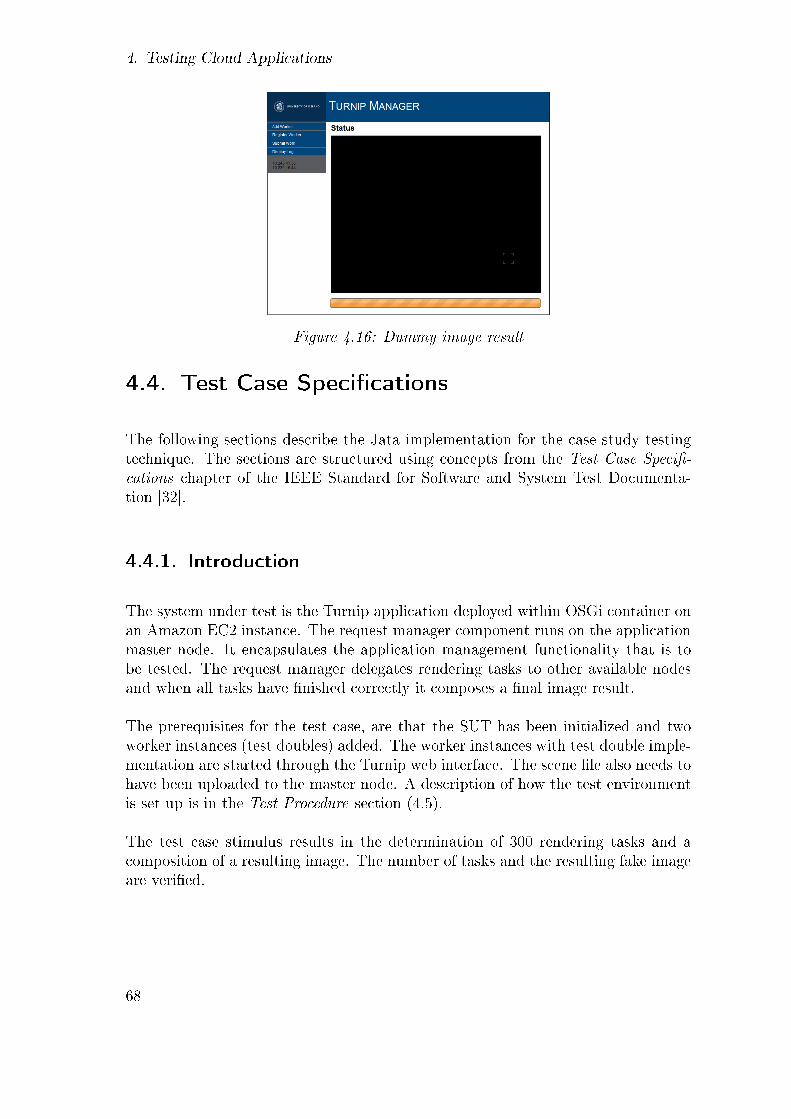
4. Testing Cloud Applications
Figure 4.16: Dummy image result
4.4. Test Case Speci�cations
The following sections describe the Jata implementation for the case study testingtechnique. The sections are structured using concepts from the Test Case Speci�-cations chapter of the IEEE Standard for Software and System Test Documenta-tion [32].
4.4.1. Introduction
The system under test is the Turnip application deployed within OSGi container onan Amazon EC2 instance. The request manager component runs on the applicationmaster node. It encapsulates the application management functionality that is tobe tested. The request manager delegates rendering tasks to other available nodesand when all tasks have �nished correctly it composes a �nal image result.
The prerequisites for the test case, are that the SUT has been initialized and twoworker instances (test doubles) added. The worker instances with test double imple-mentation are started through the Turnip web interface. The scene �le also needs tohave been uploaded to the master node. A description of how the test environmentis set up is in the Test Procedure section (4.5).
The test case stimulus results in the determination of 300 rendering tasks and acomposition of a resulting image. The number of tasks and the resulting fake imageare veri�ed.
68

4.4. Test Case Speci�cations
Objective
The testing focus is on the work of the distribution management of the application,i.e. that distributing tasks and merging their partial rendering outputs works asexpected. The test checks if the management determines the tasks correctly anddistributes all of them to the available cloud nodes correctly. The communicationbetween distributed components in the cloud is under inspection.
Inputs
No parameters are needed in the request stimulation at the start of the test case.The determination of rendering tasks is based on the preloaded scene �le, whichis uploaded to the master node by a test bootstrapping utility when the SUT isinitialized. The utility, made for this case study, is described in section 4.5. Thenumber of workers is also decided and launched with the test utility.
4.4.2. Test Case Structure
The Java code for the test case is shown in listing 4.1.
1 public class tc_TestTheApplicationManagement extends TestCase<Mtc , Sys>{2 private St r ing sutIpAddress ;3 private Map<Integer , MsgReceivedJob> rece ivedJobMessages = new
HashMap<Integer , MsgReceivedJob >() ;4 private stat ic int EXPECTED_TASK_MESSAGES_COUNT = 300 ;5 private stat ic int EXPECTED_FILE_SIZE = 3247 ; // s i z e o f 300 b l a c k
image par t s67 public TAM_TestCase( S t r ing [ ] a rgs ) throws Exception {8 super (Mtc . class , Sys . class ) ;9 }1011 @Override12 protected void Case (Mtc mtc , Sys sys ) throws JataException {13 Ptc ptc1 = createPtc ( Ptc . class ) ;14 Ptc ptc2 = createPtc ( Ptc . class ) ;1516 PipeCenter .Map( ptc1 . pt_PS , sys . pt_PTC1) ; // PTC−1 <−> System17 PipeCenter .Map(mtc . pt_MP1, ptc1 .pt_PM) ; // PTC−1 <−> MTC18 PipeCenter .Map( ptc2 . pt_PS , sys . pt_PTC2) ; // PTC−2 <−> System19 PipeCenter .Map(mtc . pt_MP1, ptc2 .pt_PM) ; // PTC−2 <−> MTC20 PipeCenter .Map(mtc . pt_system , sys . pt_http ) ; // MTC − System2122 try {23 // Send s t imu lu s
69
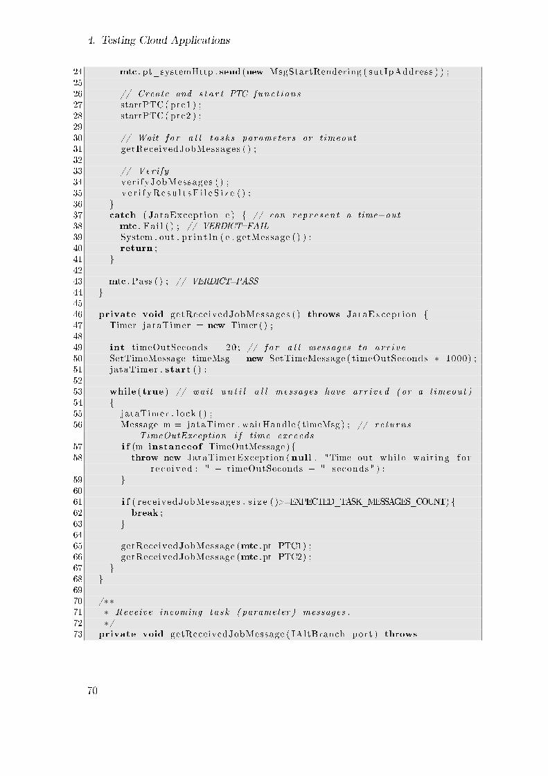
4. Testing Cloud Applications
24 mtc . pt_systemHttp . send (new MsgStartRendering ( sutIpAddress ) ) ;2526 // Create and s t a r t PTC func t i on s27 startPTC ( ptc1 ) ;28 startPTC ( ptc2 ) ;2930 // Wait f o r a l l t a s k s parameters or t imeout31 getReceivedJobMessages ( ) ;3233 // Ver i fy34 ver i fyJobMessages ( ) ;35 v e r i f yR e s u l t s F i l e S i z e ( ) ;36 }37 catch ( JataException e ) { // can rep re s en t a time−out38 mtc . Fa i l ( ) ; // VERDICT=FAIL39 System . out . p r i n t l n ( e . getMessage ( ) ) ;40 return ;41 }4243 mtc . Pass ( ) ; // VERDICT=PASS44 }4546 private void getReceivedJobMessages ( ) throws JataException {47 Timer jataTimer = new Timer ( ) ;4849 int timeOutSeconds = 20 ; // f o r a l l messages to a r r i v e50 SetTimeMessage timeMsg = new SetTimeMessage ( timeOutSeconds ∗ 1000) ;51 jataTimer . start ( ) ;5253 while ( true ) // wai t u n t i l a l l messages have a r r i v ed ( or a t imeout )54 {55 jataTimer . l o ck ( ) ;56 Message m = jataTimer . waitHandle ( timeMsg ) ; // re turns
TimeOutException i f time exceeds57 i f (m instanceof TimeOutMessage ) {58 throw new JataTimerException (null , "Time out whi l e wa i t ing f o r
r e c e i v ed : " + timeOutSeconds + " seconds " ) ;59 }6061 i f ( rece ivedJobMessages . s i z e ( )>=EXPECTED_TASK_MESSAGES_COUNT){62 break ;63 }6465 getReceivedJobMessage (mtc . pt_PTC1) ;66 getReceivedJobMessage (mtc . pt_PTC2) ;67 }68 }6970 /∗∗71 ∗ Receive incoming ta s k ( parameter ) messages .72 ∗/73 private void getReceivedJobMessage ( IAltBranch port ) throws
70

4.4. Test Case Speci�cations
JataException {74 Alt alt = new Alt ( ) ;75 Timer t = new Timer ( ) ;76 t . start ( ) ;7778 alt . addBranch ( port , new MsgReceivedJob ( ) ) ;79 alt . addBranch ( t , new SetTimeMessage (2000) ) ;80 alt . proc ( ) ;8182 i f ( alt . g e tResu l t ( ) . index ==0){83 MsgReceivedJob msg = (MsgReceivedJob ) alt . g e tResu l t ( ) . Result ;8485 int indexId = msg . getParameters ( ) . getBucketId ( ) /2 ;86 rece ivedJobMessages . put ( indexId , msg) ;87 }88 else {89 // Ignore : The t e s t case p o l l s the message−queue90 // r e gu l a r l y , so i t can normal ly be empty at t imes .91 }92 }9394 private void ver i fyJobMessages ( ) {95 i f ( rece ivedJobMessages . s i z e ( ) != EXPECTED_TASK_MESSAGES_COUNT){96 throw new JataException ( "FAILURE: Number o f r e c e i v ed task
messages should be : " + EXPECTED_TASK_MESSAGES_COUNT) ;97 }98 // e l s e cont inue . . = mtc . Pass99 }100101 private void v e r i f yR e s u l t s F i l e S i z e ( ) throws JataException {102 mtc . pt_systemHttp . send (new MsgGetImage ( sutIpAddress ) ) ;103104 Alt alt = new Alt ( ) ;105 Timer t = new Timer ( ) ;106 t . start ( ) ;107108 alt . addBranch (mtc . pt_systemHttp , new MsgGetImageResponse ( ) ) ;109 alt . addBranch ( t , new SetTimeMessage (3000) ) ;110 alt . proc ( ) ;111112 AltResu l t r = alt . g e tResu l t ( ) ;113114 i f ( r . index == 0) {115 MsgGetImageResponse msg = (MsgGetImageResponse ) alt . g e tResu l t ( ) .
Result ;116117 F i l e f i l e = ( F i l e )msg . Coder ( ) ;118119 i f (EXPECTED_FILE_SIZE != f i l e . l ength ( ) ) {120 throw new JataAssertExcept ion ( " Fa i l u r e . Expected r e s u l t f i l e
s i z e : " + EXPECTED_FILE_SIZE + " . Actual s i z e : " + f i l e .l ength ( ) ) ;
71

4. Testing Cloud Applications
121 }122 System . out . p r i n t l n ( "Result f i l e s i z e c o r r e c t . " ) ;123 }124 else {125 throw new JataAssertExcept ion ( " Fa i l u r e in r e c e i v i n g image" ) ;126 }127 }128 }
Listing 4.1: Jata test case implementation
The private variables of the test case class are used in stimulation and expectations.The structure of the test case Java method complies to the general test case structureof Jata and TTCN-3. First the PTCs are created (lines 13 and 14), and thenthe communication ports are mapped (lines 16-20), i.e. connected with each otheraccording to the test architecture. In Jata only local executed ports can be mappedwith the PipeCenter methods. Therefore the ports being mapped in the test casecan only be between test components (MTC and PTCs) or the system adapter(SystemComponent). Remote ports cannot be mapped with Jata library methodsand need to be manually con�gured (with RMI). After the con�guration of testcomponents and ports the stimulus is sent (line 24). Then the PTC test functionsare created and started (lines 27-28).
The getReceivedJobMessages method (line 46) waits for all rendering messages toarrive before continuing the test case. The method con�gures the timeout for re-ceiving all rendering job messages to be 20 seconds (line 49) before starting a loop(line 53) to collect the received job messages that the PTCs have received from thetest doubles (lines 66 and 66). The getReceivedJobMessage method (line 73) is calledperiodically for both PTCs until another timeout occurs or all 300 messages havearrived. If the job message from a PTC is the last one according to the expectednumber of messages, the loop can break (line 61), and the test case continues to the�nal veri�cation.
The getReceivedJobMessage method (line 73) uses an alt statement to receive mes-sages through a PTC port of the MTC (line 78). When a PTC receives a messagefrom the test double it forwards it to the MTC. The PTC test function behavior isdescribed in listing 4.12. The alt statement contains a timeout de�nition (line 79)so that the method does not get blocked if the PTC has not sent a message withina certain time, or has �nished sending all the messages. The 'outer' timeout of 20seconds (lines 49-51) is the timeout for all the messages to arrive. The Jata Timerclass is used for the timeout handle but Java Date/Time methods could also havebeen used. The jataTimer.start method (line 51) starts the timer. The jataTimer.lockmethod (line 55) stops (or locks) the time measurement, from the timer start to thepoint of the lock. It is therefore possible to call the lock method in every round ofthe loop until the de�ned timeout is received. The elapsed time is checked within
72

4.4. Test Case Speci�cations
the jataTimer.waitHandle method. The timer returns a message of TimeOutExceptionin case of a timeout (line 56).
When a message about a task submission is received at a MTC port, it is added tothe map collection of receivedJobMessages, a member variable of the MTC (line 86).The bucket ID is contained in the message (line 85), so it is possible to make surethat the same bucket information is not received twice or that all 300 bucket IDsare received. (The division by 2 in line 85 is a way to deal with a 'bug' in the SUT,which creates only even number bucket IDs).
The verify method calls (lines 34 and 35) make two di�erent assertions for the testcase. The verifyJobMessages method (line 94) veri�es that indeed 300 tasks wereused to render the image. When the test case has received expected number oftask messages (line 95), de�ned with the EXPECTED_TASK_MESSAGES_COUNTconstant, the test case can continue. If all messages do not arrive in the de�ned time,the test case ends with a failure. The verifyResultsFileSize (line 101) veri�es the disk�le size of the completed fake image. It uses the HTTP port to fetch the image asa Java File object for veri�cation of its size. The method uses an alt statement asthe structure. The total size of 300 black image parts is exactly 3247 bytes (line119), de�ned with the EXPECTED_FILE_SIZE constant. The HTTP port returns aMsgGetImageResponse message result which contains the image coded as a �le object(line 117).
Test Components and the System Adapter
Following listings (4.2, 4.3, 4.4) show the structure of the test components (MTCand PTCs) and the system adapter of the test case. The relationship between thecomponents and communication ports is depicted in �gure 4.12.
1 public class Mtc extends j a t a . Component . TestComponent {2 public PortMP pt_PTC1 ; // por t to PTC−13 public PortMP pt_PTC2 ; // por t to PTC−24 public PortSystem pt_system ; // mapped to system HTTP por t56 public Mtc ( ) throws Exception {7 super ( ) ;8 pt_PTC1 = new PortMP( ) ;9 pt_PTC2 = new PortMP( ) ;10 pt_system = new PortSystem ( ) ;11 }12 }
Listing 4.2: Main Test Component
73

4. Testing Cloud Applications
The MTC is shown in listing 4.2. It has an abstract output port (pt_system) whichis mapped to the system HTTP port for sending stimulation message to the SUT viaHTTP. It has also input ports (pt_PTC1 and pt_PTC1) for the bucket informationmessages received from the PTCs.
1 public class Ptc extends TestComponent {2 public PortPS pt_system ; // por t to system ( adapter )3 public PortPM pt_mtc ; // por t to mtc45 public Ptc ( ) throws Exception {6 super ( ) ;7 pt_system = new PortPS ( ) ;8 pt_mtc = new PortPM() ;9 }10 }
Listing 4.3: Parallel Test Component
Listing 4.3 shows the PTC de�nition which includes the port de�nitions to the MTC(pt_mtc) and the system adapter (pt_system).
1 public class Sys extends SystemComponent{2 public PortSP pt_PTC1 ;3 public PortSP pt_PTC2 ;4 public PortSystemHttp pt_http ;56 public Sys ( ) throws Exception {7 pt_PTC1 = new PortSP ( Config . getRmiConfig ( "PTC−1" ) ) ;8 pt_PTC2 = new PortSP ( Config . getRmiConfig ( "PTC−2" ) ) ;9 pt_http = new PortSystemHttp ( ) ;10 }11 }
Listing 4.4: System Component/Adapter
The SystemComponent, in listing 4.4, includes de�nitions for three ports. One (out-going) system port for HTTP stimulation of the SUT (pt_http), and two (incoming)RMI system ports mapped to each of the de�ned PTC (pt_PTC1 and pt_PTC2).The RMI system ports support RMI functionality to receive messages from the SUT.The Con�g class makes sure that each system port is initialized with a distinct RMIport number.
74

4.4. Test Case Speci�cations
Messages
TheMessage object plays a vital role in a Jata test architecture. The communicationports use message objects as a means of data transfer. The Jata message includesmethods for data encoding and decoding. Listing 4.5 shows the message for 'startrendering' stimulation. The message includes the IP address of the SUT (line 2) sothat the HTTP system port can construct the correct HTTP request (the HTTPport is described in listing 4.9). The message only contains a coding method (line19) and not decoding because it is only used to stimulate the SUT and not to receivea response.
1 public class MsgStartRendering extends Message{2 private St r ing sutIpAddress ;34 public MsgStartRendering ( ) {5 this ( ( Message ) null ) ;6 }78 public MsgStartRendering ( S t r ing sutIpAddress ) {9 this ( ( Message ) null ) ;10 this . sutIpAddress = sutIpAddress ;11 }1213 public MsgStartRendering (Message parent ) {14 super ( parent ) ;15 codeToType = " java . lang . S t r ing " ;16 }1718 @Override19 protected Object Coder ( ) throws JataException {20 return sutIpAddress ;21 }22 }
Listing 4.5: Message 'Start rendering'
Listing 4.6 shows the response message created by the HTTP port after the startrendering message has been sent to the port and handled. This particular messagecould be analyzed in the test case method but is not. Instead the decoding method(line 13) throws an assert exception if the HTML string from the stimulation is in-correct (line 19). In principle the test case method should include an alt statementand perform this veri�cation instead of the message, but it was not done for thesake of simplicity.
1 public class MsgSutResponse extends Message{23 public MsgSutResponse (Message parent ) {
75

4. Testing Cloud Applications
4 super ( parent ) ;5 decodeFromType = " java . lang . S t r ing " ;6 }78 public MsgSutResponse ( ) {9 this ( null ) ;10 }1112 @Override13 protected boolean Decoder ( Object stream ) throws Exception {14 St r ing content = ( St r ing ) stream ;1516 // "Request submited !" s t r i n g i s the r e s u l t from the Turnip
a j a x S e r v l e t a f t e r s t a r t i n g a render ing job .17 i f ( ! "Request submited ! " . equa l s IgnoreCase ( content ) ) {18 throw new JataAssertExcept ion ( "Unexptected s t imu la t i on r e s u l t " ) ;19 }20 }21 }
Listing 4.6: Message 'Stimulation response'
The MsgReceivedJob, shown in listing 4.7, is used for the information about ren-dering jobs. It includes a JobParameters object (line 2), which holds the actualinformation. The de�nition of the JobParameter class is included in the listing (line39). The JobParameter class is simply a wrapper for the bucket information.
1 public class MsgReceivedJob extends Message implements S e r i a l i z a b l e {2 private JobParameters jobParameters = null ;34 public MsgReceivedJob (Message parent ) {5 super ( parent ) ;6 codeToType = " i s . h i . j a t a . example . pa ramete r t e s t ca s e . turn ip .
JobParameters " ;7 decodeFromType = " i s . h i . j a t a . example . pa ramete r t e s t ca se . turn ip .
JobParameters " ;8 }910 public MsgReceivedJob ( ) {11 this ( ( Message ) null ) ;12 }1314 public MsgReceivedJob ( JobParameters jobParameters ) {15 this ( ( Message ) null ) ;16 this . jobParameters = jobParameters ;17 }1819 public JobParameters getParameters ( ) {20 return jobParameters ;21 }22
76

4.4. Test Case Speci�cations
23 @Override24 protected Object Coder ( ) throws JataException {25 return jobParameters ; // no coding requ i r ed . s imply us ing the POJO26 }2728 @Override29 protected boolean Decoder ( Object stream ) throws Exception {30 i f ( stream instanceof JobParameters ) {31 this . jobParameters = ( JobParameters ) stream ;32 return true ;33 }34 else
35 return fa l se ;36 }37 }3839 public class JobParameters implements S e r i a l i z a b l e {4041 private int workerId ;42 private int bucketId ;43 private int frame ;4445 . . . g e t t e r s and s e t t e r s omitted from the l i s t i n g46 }
Listing 4.7: Message 'Received job'
The last message described here is the MsgGetImageResponse, which the HTTP sys-tem port sends as a response when the MTC fetches the image result. The messageencapsulates a Java File object which contains the composed image.
1 public class MsgGetImageResponse extends Message implements
S e r i a l i z a b l e {23 private F i l e f i l e = null ;45 public MsgGetImageResponse (Message Father ) {6 super ( Father ) ;7 codeToType = " java . i o . F i l e " ;8 decodeFromType = " java . i o . F i l e " ;9 }1011 public MsgGetImageResponse ( ) {12 this ( null ) ;13 }1415 @Override16 protected Object Coder ( ) throws JataException {17 return f i l e ;18 }19
77
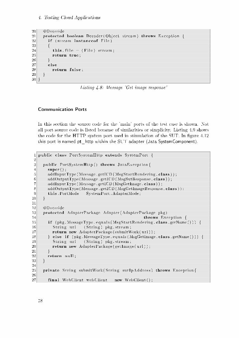
4. Testing Cloud Applications
20 @Override21 protected boolean Decoder ( Object stream ) throws Exception {22 i f ( stream instanceof F i l e )23 {24 this . f i l e = ( F i l e ) stream ;25 return true ;26 }27 else
28 return fa l se ;29 }30 }
Listing 4.8: Message 'Get image response'
Communication Ports
In this section the source code for the 'main' ports of the test case is shown. Notall port source code is listed because of similarities or simplicity. Listing 4.9 showsthe code for the HTTP system port used in stimulation of the SUT. In �gure 4.12this port is named pt_http within the SUT adapter (Jata SystemComponent).
1 public class PortSystemHttp extends SystemPort {23 public PortSystemHttp ( ) throws JataException {4 super ( ) ;5 addInputType (Message . getICD (MsgStartRendering . class ) ) ;6 addOutputType (Message . getICD (MsgSutResponse . class ) ) ;7 addInputType (Message . getICD (MsgGetImage . class ) ) ;8 addOutputType (Message . getICD (MsgGetImageResponse . class ) ) ;9 this . PortMode = SystemPort . AdapterMode ;10 }1112 @Override13 protected AdapterPackage Adapter ( AdapterPackage pkg )14 throws Exception {15 i f ( pkg . MessageType . equa l s ( MsgStartRendering . class . getName ( ) ) ) {16 St r ing u r l = ( St r ing ) pkg . stream ;17 return new AdapterPackage ( submitWork ( u r l ) ) ;18 } else i f ( pkg . MessageType . equa l s (MsgGetImage . class . getName ( ) ) ) {19 St r ing u r l = ( St r ing ) pkg . stream ;20 return new AdapterPackage ( getImage ( u r l ) ) ;21 }22 return null ;23 }2425 private St r ing submitWork ( St r ing sutIpAddress ) throws Exception {2627 f ina l WebClient webClient = new WebClient ( ) ;
78

4.4. Test Case Speci�cations
2829 St r ing ajaxMethod = "makeRequest" ;30 St r ing ajaxUr l = "http :// " + sutIpAddress + " :9000/ turn ip / ajax /" +
method ;3132 f ina l HtmlPage page = webClient . getPage ( a jaxUr l ) ;33 f ina l St r ing pageAsText = page . asText ( ) ;34 as se r tTrue ( pageAsText . conta in s ( "work submitted " ) ) ;35 webClient . closeAllWindows ( ) ;3637 return pageAsText ;38 }3940 private F i l e getImage ( S t r ing sutIpAddress ) throws Exception {41 St r ing f i l e U r l = "http :// " + sutIpAddress + " :9000/ images /
sunflowImage . png" ;4243 HttpCl ient c l i e n t = new Defau l tHttpCl i ent ( ) ;44 HttpGet httpget = new HttpGet ( f i l e U r l ) ;45 HttpContext context = new BasicHttpContext ( ) ;46 HttpResponse getResponse = c l i e n t . execute ( httpget , context ) ;4748 St r ing r e spon s e s t a tu s = getResponse . ge tStatusL ine ( ) . t oS t r i ng ( ) ;49 i f ( !STATUS_OK. equa l s ( r e spon s e s t a tu s ) ) {50 throw new Exception ( "Result f i l e s t a t u s l i n e f a i l e d . " ) ;51 }5253 URL ur l = new URL( f i l e U r l ) ;54 BufferedImage image = ImageIO . read ( u r l ) ;5556 St r ing workingDir = System . getProperty ( " user . d i r " ) ;5758 F i l e f i l e = new F i l e ( workingDir + "/ r e s u l t . png" ) ;59 ImageIO . wr i t e ( image , "png" , f i l e ) ;6061 return f i l e ;62 }63 }
Listing 4.9: HTTP system port
All ports de�ne their input and output message types in the constructor (lines 5 to 8).The input/output message types are used from the owner component perspective,i.e. input type message is a stimulation message. The message is sent 'in' to the port,which then uses it for outgoing calls to the SUT. Output type message is a messagewhich goes 'out' from the port, i.e. response message after the port is called via the'send' method. For instance if an MTC port and a system port are mapped togetherthe MTC port sends an 'input' type message to the system port, which returns thecall with an 'output' type message. The system HTTP port has an input messagetype de�ned as 'start rendering' (line 5) with a corresponding output type as 'SUT
79

4. Testing Cloud Applications
response' (line 6). For the �nal image downloading, the port contains a 'get image'input type (line 7) and a corresponding 'get image response' output message (line8).
System ports override the Adapter method (line 11) which is called by the Jataframework when messages are sent to the ports. The Adapter method is overriddento create the appropriate stimulation request for the SUT. There are two ways ofsending messages with the port and the message type is used to distinquish betweenthe options (line 15 and 18). The IP address of the SUT web server is used to createthe correct HTML request for either request.
For the 'start rendering' stimulation in method submitWork (line 25), the port usesHtmlUnit7, a Java HTML test library, for communication with the SUT web appli-cation. The Turnip web application is implemented with AJAX so that requests,such as starting a rendering job, can be made directly with URL requests. UsingHtmlUnit also gives the opportunity of making assertions on the returned HTMLcontent (e.g. line 27). The URL for submitting rendering job in Turnip looks like:
http://APPLICATION-HOST:9000/turnip/ajax/makeRequest.
For the 'get image' feature of the port, de�ned in method getImage (line 40), the portuses Apache HttpClient8, because HtmlUnit does not support image downloading.The communication is set up with HttpClient (lines 43 to 46) and the ImageIO classused to download the image (line 54). The image is written to the test system �ledirectory also with the help of ImageIO (line 59). The reason why it is written to adisk is that then it can be encapsulated as a Java File object for �le size veri�cation(line 61). The request URL for the image is:
http://APPLICATION-HOST:9000/images/sunflowImage.png.
Abstract Ports
Abstract ports are used to link test components together or to link test componentswith the system adapter. Their de�nition is generally simple and does not need anyextra coding as the system ports. Listing 4.10 shows an abstract port that does notimplement any behavior, only input and output message de�nitions. The PortPS isowned by an PTC and maps to a system port. PTCs receive job task submissionmessages with information about tasks (buckets) through this port. The de�nedinput type message is 'received job' (line 4). Other abstract ports are just as simple
7HtmlUnit. http://htmlunit.sourceforge.net/8Apache HttpClient. http://hc.apache.org/httpcomponents-client-ga/index.html/
80

4.4. Test Case Speci�cations
and do not need to be listed here. The seven test components' ports seen in the testarchitecture diagram in �gure 4.12, are all abstract ports (PortPS is used to imple-ment the ones identi�ed as pt_sys within the PTCs in the architecture diagram).
1 public class PortPS extends AbstractPort {2 public PortPS ( ) throws JataException {3 super ( ) ;4 addInputType (Message . getICD (MsgReceivedJob . class ) ) ;5 }6 }
Listing 4.10: PTC's abstract port
Remote Port (Within the Test Double Worker)
The remote port is owned by the test double implementation of the worker. Listing4.11 shows the code for the whole test double. The test double architecture andbehavior was described in Section 4.3.3. The test double extends the actual SUTworker component (line 1) and is deployed on the worker instance in the cloud. Thetest double only overrides the run method (line 11) of its parent, which is called bythe Request Manager.
The run method starts by setting up the communication port to the test systemadapter, in a call to the con�gJata method (line 12). As stated earlier remote portsneed a manual con�guration between the ports involved. Information about thesystem adapter port is uploaded in a con�guration �le to the worker cloud instancewhen it is started. The initialization procedure, described in section 4.5, takes careof uploading the con�guration information.
After con�guration of the test double a new thread is started for handling renderingtasks (lines 14 to 19). The render method (line 34) asks for next bucket to render(line 37) and sends information about the task to the test system (line 38), throughthe remote port. The PortWorkerToPtc (declared in line 6) is an RMI port for send-ing messages via RMI to a Jata system adapter port (line 47). The receiving systemadapter port is mapped to an abstract port of a PTC (see �gure 4.12).
1 public class WorkerComponentTestDouble extends WorkerComponent {2 /∗∗3 ∗ Jata remote por t d e f i n i t i o n4 ∗/5 private PortWorkerToPtc portWorkerToPtc = null ;67 /∗∗8 ∗ S t a r t s the render ing ( c a l l e d by the r e que s t manager )
81

4. Testing Cloud Applications
9 ∗/10 @Override11 public void run ( ) {12 con f i gJa ta ( ) ;1314 renderThread = new Thread (new Runnable ( ) {15 public void run ( ) {16 render ( ) ;17 }18 }) ;19 renderThread . start ( ) ;20 }2122 private void con f i gJa ta ( ) throws Exception {23 FakeRenderWorkerConfiguration con f i g = new
FakeRenderWorkerConfiguration ( ) ;24 c on f i g . workerId = Config . getWorkerId ( ) ;25 c on f i g . ptcRmiConf igurat ion = Config . getPtcConf ig ( ) ;2627 try {28 portWorkerToPtc = new PortWorkerToPtc ( c on f i g . ptcRmiConfigurat ion )
;29 } catch ( Exception e ) {30 System . out . p r i n t l n ( "WARNING: Could not c r e a t e PortToMtc" ) ;31 }32 }3334 private void render ( ) {35 while ( ! doBreak ( ) ) {36 try {37 currentBucket = requestManager . getNextBucket ( currentFrame ,
workerId ) ;38 sendParametersToJata ( ) ;39 } catch ( EmptyStackException e ) {40 break ; // s top render ing41 }42 }43 }4445 private void sendParametersToJata ( ) {46 try {47 portWorkerToPtc . pipe2Me (new MsgReceivedJob (new JobParameters (
workerId , currentBucket . id , currentFrame ) ) ) ;48 } catch ( JataPortException e ) {49 System . out . p r i n t l n ( "Render worker−" + workerId + " f a i l e d to send
message to t e s t system : " + e . getMessage ( ) ) ;50 }51 }52 }
Listing 4.11: Worker's Rendering Test Double
82

4.4. Test Case Speci�cations
PTC test function behavior
This section describes the behavior of the PTC test function. The function sourcecode is in listing 4.12.
1 public class ParameterPtcTestFunc extends TestFunction<Ptc>{23 @Override4 public void Func ( Ptc ptc ) throws JataException {5 getReceivedJobMessages (ptc ) ;6 ptc . Pass ( ) ;7 }89 private void getReceivedJobMessages ( Ptc ptc ) throws JataException {10 Timer jataTimer = new Timer ( ) ;1112 int timeOutSeconds = 120 ;13 SetTimeMessage timeMsg = new SetTimeMessage ( timeOutSeconds ∗ 1000) ;14 jataTimer . start ( ) ;1516 while ( true ) {17 jataTimer . l o ck ( ) ;18 Message m = jataTimer . waitHandle ( timeMsg ) ;19 i f (m instanceof TimeOutMessage ) {20 // Time out e x c ep t i on s are caught in the MTC, which has another
loop f o r r e t r i e v i n g t h e s e messages .21 break ;22 }23 rece iveMessage (ptc ) ;24 }25 }2627 /∗∗28 ∗ Wait f o r incoming ta s k ( parameter ) messages from29 ∗ the t e s t−doub le worker remote−por t .30 ∗/31 private void rece iveMessage ( Ptc ptc ) throws JataException {32 Alt alt = new Alt ( ) ;33 Timer t = new Timer ( ) ;34 t . start ( ) ;3536 alt . addBranch (ptc . pt_system , new MsgReceivedJob ( ) ) ;37 alt . addBranch ( t , new SetTimeMessage (2000) ) ;38 alt . proc ( ) ;3940 i f ( alt . g e tResu l t ( ) . index == 0) {41 MsgReceivedJob msg = (MsgReceivedJob ) alt . g e tResu l t ( ) . Result ;4243 // "Forward" PTC' s incoming parameter message to the MTC44 ptc .pt_MTC. send (msg) ;45
83

4. Testing Cloud Applications
46 // I d e a l l y send a r e s u l t image−par t to the SUT.47 // ptc . portPS_out . send (new MsgImagePart ( ) ) ; −> Not ' p o s s i b l e '48 }49 else {50 // Ignore : The t e s t f unc t i on p o l l s the message−queue51 // r e gu l a r l y , so i t can normal ly be empty at t imes .52 }53 }54 }
Listing 4.12: PTC test function
The purpose of this PTC test function is to retrieve the messages that the paralleltest component receives from the SUT, and forward them to the MTC for analysisand veri�cation.
The PTC function is started in the main test case method (listing 4.1 lines 26 and27). In this test case the MTC is responsible for collecting all bucket informationmessages for veri�cation, and with this implementation, the MTC has all the mes-sages and knowledge needed for validation of all the messages.
Just like the MTC (listing 4.1 line 46) the PTC function class de�nes a getReceived-JobMessages method (line 9). The reason is that the worker test double remote portsends the initial message to a system adapter port which forwards it to the PTC.When the PTC receives such a message it instantly forwards it to the MTC throughits abstract port which is mapped to a MTC port.
In the getReceivedJobMessages method a timer is started (lines 12 to 14) beforeentering a loop which receives all incoming messages within the de�ned timeout.The timeout is made large enough for all rendering tasks to �nish. The MTC isresponsible for de�ning and controlling the timeout of the whole test case. In theloop a call to the receiveMessage method (line 23) is made to receive each messagefrom the system port. The receiveMessage method includes an alt statement whichis made in the usual way (lines 36 to 38). For each MsgReceivedJob message received(line 40) the message is forwarded to the MTC (line 44). Line 47 shows where imageparts should in principle be created and sent to the SUT if it were possible. Thetest double workaround for the dummy image creation and sending is described inSection 4.3.3.
4.5. Test Procedure
This section is structured using concepts from the Test Procedure chapter of theIEEE Standard for Software and System Test Documentation [32].
84
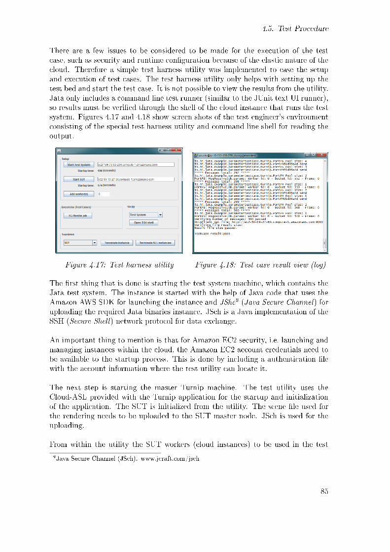
4.5. Test Procedure
There are a few issues to be considered to be made for the execution of the testcase, such as security and runtime con�guration because of the elastic nature of thecloud. Therefore a simple test harness utility was implemented to ease the setupand execution of test cases. The test harness utility only helps with setting up thetest bed and start the test case. It is not possible to view the results from the utility.Jata only includes a command line test runner (similar to the JUnit text UI runner),so results must be veri�ed through the shell of the cloud instance that runs the testsystem. Figures 4.17 and 4.18 show screen shots of the test engineer's environmentconsisting of the special test harness utility and command line shell for reading theoutput.
Figure 4.17: Test harness utility Figure 4.18: Test case result view (log)
The �rst thing that is done is starting the test system machine, which contains theJata test system. The instance is started with the help of Java code that uses theAmazon AWS SDK for launching the instance and JShc9 (Java Secure Channel) foruploading the required Jata binaries instance. JSch is a Java implementation of theSSH (Secure Shell) network protocol for data exchange.
An important thing to mention is that for Amazon EC2 security, i.e. launching andmanaging instances within the cloud, the Amazon EC2 account credentials need tobe available to the startup process. This is done by including a authentication �lewith the account information where the test utility can locate it.
The next step is starting the master Turnip machine. The test utility uses theCloud-ASL provided with the Turnip application for the startup and initializationof the application. The SUT is initialized from the utility. The scene �le used forthe rendering needs to be uploaded to the SUT master node. JSch is used for theuploading.
From within the utility the SUT workers (cloud instances) to be used in the test
9Java Secure Channel (JSch). www.jcraft.com/jsch
85

4. Testing Cloud Applications
case are added. The worker machines themselves are simply added through theweb interface (AJAX) of the Turnip application master node � previously started.The worker OSGi service has been pre-con�gured to use the test double, describedin 4.3.3 instead of a real rendering implementation. An important step needs tobe made by the test harness utility at this stage. The step involves uploading acon�guration �le about the test system machine for the remote port of the testdouble to use in their RMI con�guration. The remote ports communicate with theJata system adapter of the test system and need to know the IP address and theRMI port to connect to. Because of the elastic nature of clouds this informationcannot be provided at design-time and needs to be done at run-time.
After the four cloud instances are ready (the test system, Turnip master node andtwo worker instances), the test case can be started. The test harness utility usesSSH for starting the Jata test case on the test system. The output is redirected to anoutput �le on the test system and also to the System.out console of the test harnessutility Java program � because of SSH features. The test results can therefore eitherbe viewed on the test machine or in the utility program's System.out console.
Ordered Description
Table 4.3 lists the test procedure for the most important activities in an ordereddescription, as introduced in the IEEE test procedure documentation. The tableincludes columns for the activity type and the actions/steps needed for the activity.The right-most column 'Utility' indicates whether the activity can be controlledfrom within the custom made test harness utility mentioned above.
Test Case Timing
Table 4.4 shows the mean time it takes to execute each activity in the testing. Thelaunching and setup of systems takes approximately six minutes, where each cloudinstance takes about three minutes to launch and become initialized for the test. Theworkers are started in parallel, which takes around two minutes. The test case itselfruns in approximately 24 seconds, and 32 seconds go into tearing down the systems,adding up to a total of approximately nine minutes for executing the whole test.The test bed startup should be optimized in real case scenarios by adding parallelsupport for instances startup. In this case the workers need to be started after themaster node but the test system machine could have been started in parallel with theSUT master. Individual machines should have support for restart and reinitialize. Iffor instance a tester needs to change a test case, the only thing needed is uploadingthe new test case binaries to the test system and start the test case. There would beno need to restart instances of the SUT. The same applies if code or con�guraiton�xes need to by applied to nodes of the SUT.
86
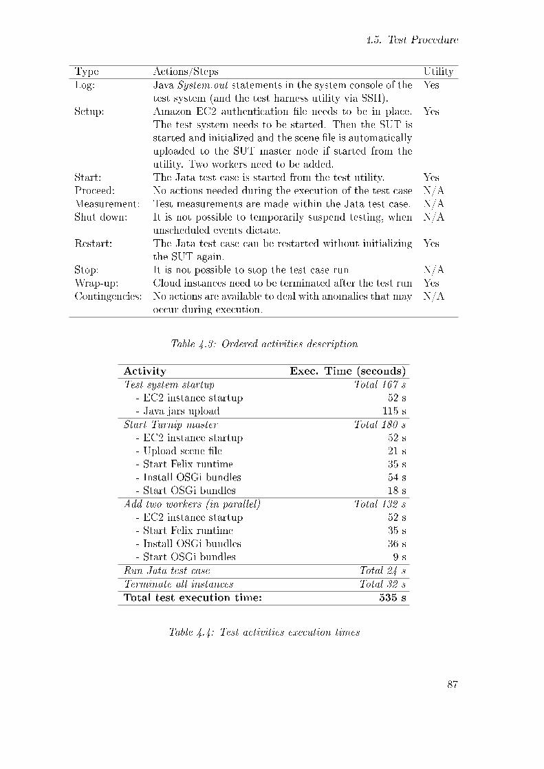
4.5. Test Procedure
Type Actions/Steps UtilityLog: Java System.out statements in the system console of the
test system (and the test harness utility via SSH).Yes
Setup: Amazon EC2 authentication �le needs to be in place.The test system needs to be started. Then the SUT isstarted and initialized and the scene �le is automaticallyuploaded to the SUT master node if started from theutility. Two workers need to be added.
Yes
Start: The Jata test case is started from the test utility. YesProceed: No actions needed during the execution of the test case N/AMeasurement: Test measurements are made within the Jata test case. N/AShut down: It is not possible to temporarily suspend testing, when
unscheduled events dictate.N/A
Restart: The Jata test case can be restarted without initializingthe SUT again.
Yes
Stop: It is not possible to stop the test case run N/AWrap-up: Cloud instances need to be terminated after the test run YesContingencies: No actions are available to deal with anomalies that may
occur during execution.N/A
Table 4.3: Ordered activities description
Activity Exec. Time (seconds)Test system startup Total 167 s
- EC2 instance startup 52 s- Java jars upload 115 s
Start Turnip master Total 180 s- EC2 instance startup 52 s- Upload scene �le 21 s- Start Felix runtime 35 s- Install OSGi bundles 54 s- Start OSGi bundles 18 s
Add two workers (in parallel) Total 132 s- EC2 instance startup 52 s- Start Felix runtime 35 s- Install OSGi bundles 36 s- Start OSGi bundles 9 s
Run Jata test case Total 24 sTerminate all instances Total 32 sTotal test execution time: 535 s
Table 4.4: Test activities execution times
87


5. Evaluation
This chapter covers an evaluation of the performed case study. The objectives aretwofold: Investigating challenges in software testing for applications running in cloudenvironment and evaluation of the applicability of Jata for distributed testing. Insection 5.1 the evaluation of software testing of cloud application is made whereassection 5.2 covers an evaluation of the Jata test framework.
5.1. Software Testing of Cloud Applications
The main result revealed by the case study is that software testing for cloud appli-cations is possible with traditional testing methods. However testing within a cloudenvironment includes certain issues such as:
• Run-time con�guration required
• MAC address license issues
• Firewall issues
The elastic nature of the cloud demands that the test harness (i.e. a test setupcontroller) has knowledge of all the machines, i.e. their IP addresses, participatingin the test bed. For con�guring distributed test components such as PTCs this'knowledge' needs to be automated by a test harness. In traditional test beds theIP addresses of participants can be con�gured at design-time in a con�guration �leor a database. Design-time con�guration of distributed cloud test components ishowever not possible and remote port mapping con�guration therefore needs to beprovided at run-time. This puts an extra burden on the test harness but can besolved in various ways. The case study in this thesis used a test harness utility forcreating the cloud instances to be used and uploaded con�guration �les about thetest case to the test instances. The con�guration �le included RMI port informationfor the remote port of the test double running on the instance.
Another concern related to the elastic behavior of instances is licensing issues. Manytest system providers, such as TTCN-3 tool providers, use MAC addresses licensing
89

5. Evaluation
schemes for their products. Licensing based on MAC addresses is problematic forthe cloud and needs to be addressed by the software vendors.
Even if cloud vendors provide good �rewall con�guration support it is recommended,for simplicity, that all participating machines in a test bed be located within thecloud. In this case study, running the test system locally and the SUT in the cloudusing RMI as communication method between them was not possible in a simplemanner due to �rewall con�guration issues between the sites. Another argument infavor of including all participants within the cloud is improved performance of testcase execution, because of the geographical location of involved instances. Mixingprivate and public cloud infrastructures in a test bed can however be a good optionfor security testing.
5.2. Jata
Jata's main bene�ts can be summarized in the following list:
• Light-weight
• Free of charge
• Common vocabulary (by using TTCN-3 concepts)
• Systematic way of de�ning test cases (by using TTCN-3 concepts)
• Java library
Jata is a light-weight Java library. Much like JUnit the only thing needed to getup and running for writing Jata test cases is including the Jata jar �le in the Javaclass-path. The framework is targeted at testing where the test cases and the com-munication with the test system interface is written in Java. Jata bene�ts fromusing Java since Java is a mature programming language, extremely powerful andyet simple. Another bene�t is that the test cases can be compiled and built togetherwith the components under test, assuming they are also developed with Java, whichmakes any changes between the test system and the SUT easier to handle. Conver-sion between types (Codecs) is much simpler, or not even needed, if both the SUTand the test system are written in the same language. Furthermore Java developersdo not need to learn a new language or syntax for the testing speci�cations.
What is good about Jata is that it borrows structuring from TTCN-3, essentiallyfrom CTMF, in designing test cases. By this Jata forces test engineers to thinkabstractly and express the software architecture by organizing the code into testcomponents (MTC and PTCs), ports, and alternatives. By using Jata a groundwork
90

5.2. Jata
is therefore laid for a common vocabulary as well as a systematic way of creating testspeci�cations. TTCN-3 is widely known and used by many professionals in various�elds. Documentation and information for TTCN-3 concepts are easily availablebut the TTCN-3 language and concepts can have some learning curve. It is howevernecessary for Jata users to know at least the basic concepts of TTCN-3.
Jata is a newly introduced technology so it does not come without limitations. Mostnotably it needs support for distribution of test components. Using Java lowers thelimitations of the framework, because theoretically the only limitations in imple-menting test cases are the limitation of Java. Workarounds, as the test doublesolution described in Section 4.3.3, can always be made. However additional encap-sulation of concepts such as support for de�nition of distributed test componentsand mapping of remote ports would improve the library base and possibly encouragetest engineers to use the framework.
Being a new framework little documentation is available. The framework is rela-tively simple, but not so that documentation is not needed. Currently the onlyavailable documentation is the introductory paper by the authors [60]. There arecode examples provided with the framework download package1. The code examplesare simple and do not deal with distributed test components, which also could useimprovements. Actually Jata does not support distribution of the test componentsthemselves. However, distributed ports may be used. The case study in this thesisuses therefore a test double on the remote port instance.
Jata also needs to be improved to generate associated test reports, instead of relyingsolely on a textual test runner. In the �rst run this might be achieved by using a logutility such as Apache log4j2 to write the test output to a �le on the test system.Result maintainability is an important aspect of testing activities. By writing theoutput to a �le the di�erent test runs can be compared. In later stages it might befeasible to write test outputs to XML �les, as JUnit is capable of, for build serversto archive and use for graphical displaying of the test results.
A minor issue with Jata, though worth noting, is that it fails in a few places onadhering to the common Java naming convention, which can be confusing. Allmethod names should start with a lowercase letter. Most notably are the Verdictclass methods ('Pass', 'Fail', 'Error' etc.), the 'UnMap' method of the IPipe interface,'Result' method of the AltResult class, and the 'Adapter' method of the SystemPortclass.
1Jata download: http://code.google.com/p/jata4test/2Apache Logging Services. http://logging.apache.org/
91

5. Evaluation
Jata improvements can be summarized as follows:
• Add support for test components distribution
• Add support for remote port mapping
• Improve documentation
• Add test reporting features
• Refactor method names
While Jata can be seen as some sort of replacement for TTCN-3, some TTCN-3concepts can only be used in an awkward way. For example, the convenient syntaxof a TTCN-3 alt statement cannot be used in Jata (Java). From that point of view,Jata test cases look rather like the code that is typically generated by TTCN-3compilers when translating TTCN-3 into some target language, e.g. Java.
92

6. Conclusion
This chapter summarizes the results and provides an outlook. The results are re-viewed and discussed in section 6.1, whereas the outlook is discussed in section 6.2.
6.1. Summary
In this thesis a test case was implemented with the Jata test framework for testing ofa cloud application. The cloud system under test and its management were analyzedin order to implement an advanced test case for a parallel computing application.The work revealed some challenges in testing of cloud applications. Software testingof cloud application needs to deal with run-time con�guration of test-beds basedon the elastic nature of clouds. Other issues deal with �rewall con�guration andtool licensing. A test harness utility was created in the thesis to support run-timecon�gurations of distributed test items.
The case study also showed that Jata is a promising test framework for distributedtesting. For the purpose of this thesis, Jata can be considered applicable for imple-mentation of black-box functional test cases for cloud applications. The softwaretesting performed with Jata contributes to assuring the quality of applications withincloud computing environment. It could be considered a weakness that Jata has onlybeen used by the authors in their introductory paper [60], however every child needsto take its �rst steps somewhere. This thesis is the second step in keeping it on itsfeet.
The importance of software testing can never be stressed enough. Recently AmazonAWS experienced a major outage in one of its region service1. Amazon EC2 usesmultiple geographic regions to make their services more reliable. Amazon EC2 iscurrently available in �ve regions: US East (Northern Virginia), US West (North-ern California), EU (Ireland), Asia Paci�c (Singapore), and a second Asia Paci�c(Tokyo). Each region contains multiple availability zones claimed to be designedto be insulated from failures in other availability zones2. The outage was caused
1http://news.cnet.com/8301-30685_3-20056029-264.html2http://aws.amazon.com/ec2/
93

6. Conclusion
by a network event which a�ected multiple availability zones in the US-East region,breaking the promise on the failure handling for AWS availability zones. The outagebrought down multiple public websites using Amazon's service. The outage failureat Amazon is a reminder that both cloud customers and cloud vendors need to beprepared for an outage. Distributed testing techniques help to explore and preparefor the various types of failures that can occur within cloud infrastructures.
6.2. Outlook
This work on software testing cloud applications can be used to support furtherresearch in the area. Improvements in the Jata framework can be, and should be,made. Support for distributed parallel testing components is needed in Jata asopposed to running all test components in the local context of the test system.Remote port mapping between distributed test components needs improvementswith e.g. library con�guration methods for mapping ports. Further suggestions onJata improvements were made in the evaluation chapter (chapter 5). Jata is a light-weight alternative to TTCN-3 tools. Its strengths lie in its simplicity and Jatashould continue focusing on being a light-weight option for distributed testing.
Besides Jata improvements various new research �elds, resulting from the establish-ment of Jata, can be created. An interesting research topic is to create a TTCN-3 toJata converter, where abstract test cases could be de�ned with TTCN-3 and Javacode using Jata objects would be generated automatically.
Furthermore, the test case de�ned and implemented in this thesis can be used to runthe same tests on Eucalyptus which uses the same API as Amazon EC2. For othercloud platforms the application under test used in this case study needs howeverto be adapted. The test case in the thesis focused on the functionality of theapplication management. Additional areas to cover could include testing qualityattributes of the cloud middleware itself, with focus on performance, reliability, andsecurity. Stress testing of components such as the application management couldfurthermore be researched using Jata.
Finally, testing can be done where private and public cloud infrastructures are mixed.In this case, the test components need be distributed in a way that some test com-ponents run within a certain cloud infrastructure and others out of it. The focusshould be on test components communication. Remote ports in Jata can be usedfor such a test architecture.
94
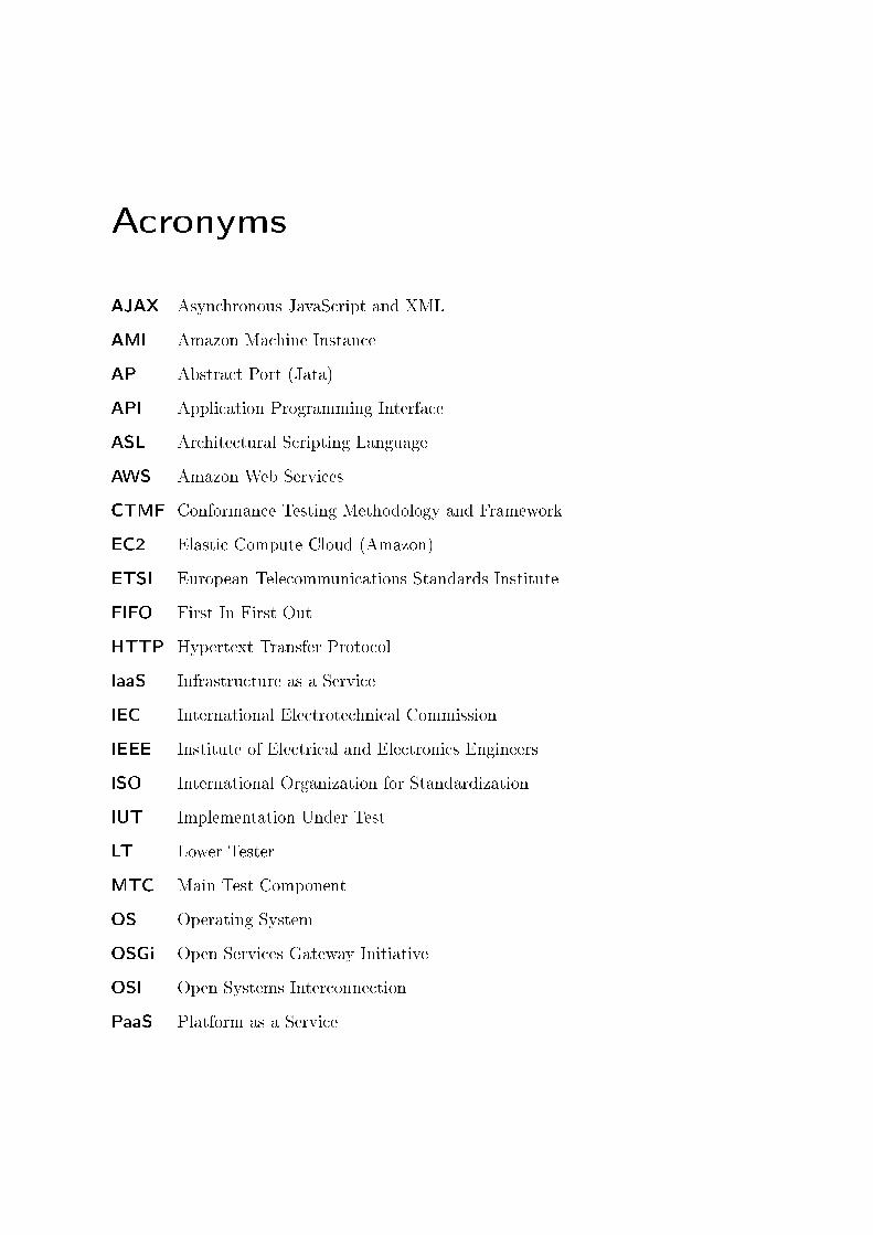
Acronyms
AJAX Asynchronous JavaScript and XML
AMI Amazon Machine Instance
AP Abstract Port (Jata)
API Application Programming Interface
ASL Architectural Scripting Language
AWS Amazon Web Services
CTMF Conformance Testing Methodology and Framework
EC2 Elastic Compute Cloud (Amazon)
ETSI European Telecommunications Standards Institute
FIFO First In First Out
HTTP Hypertext Transfer Protocol
IaaS Infrastructure as a Service
IEC International Electrotechnical Commission
IEEE Institute of Electrical and Electronics Engineers
ISO International Organization for Standardization
IUT Implementation Under Test
LT Lower Tester
MTC Main Test Component
OS Operating System
OSGi Open Services Gateway Initiative
OSI Open Systems Interconnection
PaaS Platform as a Service

Acronyms
PCO Point of Control and Observation
POJO Plain Old Java Object
PTC Parallel Test Component
RMI Remote Method Invocation
R-OSGi Remote OSGi
SaaS Software as a Service
SDK Software Development Kit
SP System Port (Jata)
SSH Secure Shell
SUT System Under Test
STITC Software Testing in the Cloud
TC Test Component
TCP Test Coordination Procedures
TP Timer Port (Jata)
TTCN-3 Testing and Test Control Notation version 3
UML Uni�ed Modeling Language
UT Upper Tester
96

Bibliography
[1] ETSI European Standard (ES) 201 873-1 V4.2.1 (2010). Methods for Testingand Speci�cation (MTS); The Testing and Test Control Notation version 3;Part 1: TTCN-3 Core Language. European Telecommunications StandardsInstitute (ETSI), Sophia-Antipolis (France), 2010.
[2] L.v.d. Aalst. Software Testing as a Service (STaaS). In PNSQC 2008. 26thAnnual Paci�c Northwest Software Quality Conference. PNSQC, 2008.
[3] OSGi Alliance. OSGi Service Platform, Release 3. IOS Press, Inc., 2003.
[4] G.S. Almasi and A. Gottlieb. Highly Parallel Computing. Benjamin-CummingsPub Co, 1994.
[5] Amazon. Amazon Elastic Compute Cloud. Getting Started Guide. http:
//docs.amazonwebservices.com/AWSEC2/latest/GettingStartedGuide/,2011.
[6] D.P. Anderson, J. Cobb, E. Korpela, M. Lebofsky, and D. Werthimer.SETI@home: An Experiment in Public-Resource Computing. Communicationsof the ACM, 45(11):56�61, 2002.
[7] M. Armbrust, A. Fox, R. Gri�th, A.D. Joseph, R.H. Katz, A. Konwinski,G. Lee, D.A. Patterson, A. Rabkin, I. Stoica, et al. Above the Clouds: ABerkeley View of Cloud Computing. EECS Department, University of Califor-nia, Berkeley, Tech. Rep. UCB/EECS-2009-28, 2009.
[8] T. Banzai, H. Koizumi, R. Kanbayashi, T. Imada, T. Hanawa, and M. Sato.D-Cloud: Design of a Software Testing Environment for Reliable DistributedSystems Using Cloud Computing Technology. In Proceedings of the 2010 10thIEEE/ACM International Conference on Cluster, Cloud and Grid Computing,pages 631�636. IEEE Computer Society, 2010.
[9] K. Beck. Extreme Programming Explained: Embrace Change. Addison-WesleyProfessional, 2000.
[10] K. Beck and E. Gamma. JUnit Test Infected: Programmers Love Writing Tests.Java Report, July 1998, Volume 3, Number 7, 1998.
97

BIBLIOGRAPHY
[11] A. Belapurkar, A. Chakrabarti, H. Ponnapalli, N. Varadarajan, S. Padmanab-huni, and S. Sundarrajan. Distributed Systems Security. Wiley, 2009.
[12] B.W. Boehm. Verifying and Validating Software Requirements and DesignSpeci�cations. Software, IEEE, 1(1):75�88, 1984.
[13] S. Bucur, V. Ureche, C. Zam�r, and G. Candea. Parallel Symbolic Executionfor Automated Real-World Software Testing. In EuroSys 2011, ACM SIGOPSEuropean Conference on Computer Systems, 2011.
[14] I. Burnstein. Practical Software Testing: a Process-Oriented Approach. SpringerVerlag, 2003.
[15] I. Burnstein, T. Suwanassart, and R. Carlson. Developing a Testing MaturityModel for software test process evaluation and improvement. In Test Confer-ence, 1996. Proceedings., International, pages 581�589, Oct. 1996.
[16] G. Candea, S. Bucur, and C. Zam�r. Automated Software Testing as a Service.In Proceedings of the 1st ACM symposium on Cloud computing, pages 155�160.ACM, 2010.
[17] WK Chan, L. Mei, and Z. Zhang. Modeling and Testing of Cloud Applications.In Services Computing Conference, 2009. APSCC 2009. IEEE Asia-Paci�c,pages 111�118. IEEE, 2009.
[18] L. Ciortea, C. Zam�r, S. Bucur, V. Chipounov, and G. Candea. Cloud9: ASoftware Testing Service. ACM SIGOPS Operating Systems Review, 43(4):5�10,2010.
[19] G.F. Coulouris, J. Dollimore, and T. Kindberg. Distributed Systems: Conceptsand Design. Addison-Wesley Longman, 2005.
[20] Å. Edlund, M. Koopmans, Z.A. Shah, I. Livenson, F. Orellana, J. Kommeri,M. Tuisku, P. Lehtovuori, K.M. Hansen, H. Neukirchen, and E. Hvannberg.Practical Cloud Evaluation from a Nordic eScience User Perspective. InVTDC11. The 5th International Workshop on Virtualization Technologies inDistributed Computing held in conjunction with the 20th International ACMSymposium on High-Performance Parallel and Distributed Computing San Jose,California, June 8-11, 2011 (to appear in ACM digital library), 2011.
[21] M. Fowler and M. Foemmel. Continuous Integration. Available on-line: http://martinfowler.com/articles/originalContinuousIntegration.html,2000.
[22] S. Freeman and N. Pryce. Growing Object-Oriented Software, Guided by Tests.Addison-Wesley Professional, 2009.
98

BIBLIOGRAPHY
[23] Z. Ganon and IE Zilbershtein. Cloud-based Performance Testing of NetworkManagement Systems. In Computer Aided Modeling and Design of Communi-cation Links and Networks, 2009. CAMAD'09. IEEE 14th International Work-shop on, pages 1�6. IEEE, 2009.
[24] J. Geelan. Twenty One Experts De�ne Cloud Computing. Virtualization, Au-gust, 2008.
[25] J. Grabowski, D. Hogrefe, G. Réthy, I. Schieferdecker, A. Wiles, and C. Will-cock. An Introduction into the Testing and Test Control Notation (TTCN-3).Computer Networks, 42(3):375�403, 2003.
[26] J. Gray and A.S. Szalay. The World Wide Telescope: An Archetype for OnlineScience. Arxiv preprint cs/0403018, 2004.
[27] L. Gu and S.C. Cheung. Constructing and testing privacy-aware services in acloud computing environment: challenges and opportunities. In Proceedings ofthe First Asia-Paci�c Symposium on Internetware, page 2. ACM, 2009.
[28] T. Hanawa, T. Banzai, H. Koizumi, R. Kanbayashi, T. Imada, and M. Sato.Large-Scale Software Testing Environment Using Cloud Computing Technol-ogy for Dependable Parallel and Distributed Systems. In Third InternationalConference on Software Testing, Veri�cation, and Validation Workshops, pages428�433. IEEE, 2010.
[29] T. Hanawa, H. Koizumi, T. Banzai, M. Sato, S. Miura, T. Ishii, andH. Takamizawa. Customizing Virtual Machine with Fault Injector by Integrat-ing with SpecC Device Model for a Software Testing Environment D-Cloud. In2010 Paci�c Rim International Symposium on Dependable Computing, pages47�54. IEEE, 2010.
[30] J. Howe. The Rise of Crowdsourcing. Wired magazine, 14(6):1�4, 2006.
[31] Steiner I. Amazon Peak Shopping Day up 44%, Kindle Becomes Its Best-selling Product. Available on-line: http://www.auctionbytes.com/cab/cab/abn/y10/m12/i28/s01, 2010. Date of publication: December 28, 2010. Dateretrieved: April 4, 2011.
[32] IEEE. Standard for Software and System Test Documentation. IEEE Std 829-2008, 2008.
[33] IEEE Standard for Software Veri�cation and Validation. IEEE Std 1012-2004.Inst. of Electrical and Electronical Engineers, 2004.
[34] M. Ingstrup and K.M. Hansen. Modeling Architectural Change: Architecturalscripting and its applications to recon�guration. In Software Architecture, 2009& European Conference on Software Architecture. WICSA/ECSA 2009. JointWorking IEEE/IFIP Conference on, pages 337�340. IEEE, 2009.
99

BIBLIOGRAPHY
[35] A. Iosup, S. Ostermann, N. Yigitbasi, R. Prodan, T. Fahringer, and D. Epema.Performance analysis of cloud computing services for many-tasks scienti�c com-puting. IEEE Transactions on Parallel and Distributed Systems, 2011.
[36] ISO/IEC. Information Technology, Open Systems Interconnection, Confor-mance Testing Methodology and Framework. International ISO/IEC multipartstandard no. 9646. ISO/IEC, 1994-1997.
[37] A. Khajeh-Hosseini, I. Sommerville, and I. Sriram. Research Challenges forEnterprise Cloud Computing. Arxiv preprint arXiv:1001.3257, 2010.
[38] T.M. King and A.S. Ganti. Migrating Autonomic Self-Testing to the Cloud. InThird International Conference on Software Testing, Veri�cation, and Valida-tion Workshops, pages 438�443. IEEE, 2010.
[39] C. Kulla. Sun�ow Rendering System Tutorial. http://www.foro3d.com/f214/sunflow-rendering-system-tutorial-76462.html, 2009. Date of publica-tion: Juny 2, 2009. Date retrieved: April 10, 2011.
[40] V. Massol and T. Husted. JUnit in Action. Manning Publications Co. Green-wich, CT, USA, 2003.
[41] P. Mell and T. Grance. The NIST De�nition of Cloud Computing. NationalInstitute of Standards and Technology, 2009.
[42] G. Meszaros. xUnit Test Patterns: Refactoring Test Code. Prentice Hall PTRUpper Saddle River, NJ, USA, 2006.
[43] H. Neukirchen. Testing Distributed and Parallel Systems with TTCN-3. [Ex-tended Abstract]. In Para 2010: State of the Art in Scienti�c and ParallelComputing, 2010.
[44] M. Oriol and F. Ullah. YETI on the Cloud. In Third International Conferenceon Software Testing, Veri�cation, and Validation Workshops, pages 434�437.IEEE, 2010.
[45] T. Parveen and S. Tilley. When to Migrate Software Testing to the Cloud? In2010 International Conference on Software Testing, Veri�cation, and Valida-tion. IEEE, 2010.
[46] S. Pota and Z. Juhasz. The bene�ts of Java and Jini in the JGrid system. InProceedings 20th IEEE International Parallel & Distributed Processing Sympo-sium, page 255. IEEE, 2006.
[47] J. Radatz. IEEE Standard Glossary of Software Engineering Terminology.IEEE Std 610121990, 121990, 1990.
[48] J. Rhoton. Cloud Computing Explained. Recursive Limited, 2010.
100

BIBLIOGRAPHY
[49] T. Rings. Testing Grid Applications Using TTCN-3. Master's thesis, Georg-August-University, Göttingen, 2007.
[50] T. Rings, H. Neukirchen, and J. Grabowski. Testing Grid Application Work-�ows Using TTCN-3. In 2008 International Conference on Software Testing,Veri�cation, and Validation, pages 210�219. IEEE, 2008.
[51] L.M. Riungu, O. Taipale, and K. Smolander. Research Issues for SoftwareTesting in the Cloud. In Cloud Computing Technology and Science (CloudCom),2010 IEEE Second International Conference on, pages 557�564. IEEE, 2010.
[52] L.M. Riungu, O. Taipale, and K. Smolander. Software Testing as an Online Ser-vice: Observations from Practice. In Third International Conference on Soft-ware Testing, Veri�cation, and Validation Workshops, pages 418�423. IEEE,2010.
[53] P. Runeson. Software Testing. Lecture at Lund University, Jan., 2011.
[54] Q. Runtao, H. Satoshi, T. Ohkawa, T. Kubota, and R. Nicolescu. DistributedUnit Testing. University paper. Available on-line: http://citr.auckland.
ac.nz/techreports/2006/CITR-TR-191.pdf, University of Auckland, NewZealand, [year missing].
[55] R. Skulason. Architectural Operations in Cloud Computing. Master's thesis,University of Iceland, Reykjavik, Iceland, 2011.
[56] H. Takabi, J.B.D. Joshi, and G. Ahn. Security and Privacy Challenges in CloudComputing Environments. Security & Privacy, IEEE, 8(6):24�31, 2010.
[57] Google Trends. Google Trends Diagram (searchwords: 'cloud computing,software testing'). http://www.google.com/trends?q=Cloud+computing%2C+Software+Testing, mars 2011.
[58] L.M. Vaquero, L. Rodero-Merino, J. Caceres, and M. Lindner. A Break in theClouds: Towards a Cloud De�nition. ACM SIGCOMM Computer Communi-cation Review, 39(1):50�55, 2008.
[59] T. Walter, I. Schieferdecker, and J. Grabowski. Test Architectures for Dis-tributed Systems-State of the Art and Beyond. In Testing of communicatingsystems: proceedings of the IFIP TC6 11th International Workshop on Testingof Communicating Systems (IWTCS'98), page 149. Citeseer, 1998.
[60] J. Wu, L. Yang, and X. Luo. Jata: A Language for Distributed ComponentTesting. In 2008 15th Asia-Paci�c Software Engineering Conference, pages145�152. IEEE, 2008.
101

A. Appendix
This appendix contains instructions on how to set up the Java development envi-ronment for the case study. Section A.1 contains description of the steps needed insetting up the environment. Section A.2 lists the tools used for the development.Section A.3 describes where the source code for the test case can be found. Finallysome considerations need to be made if the Jata core library needs to be rebuilt,which is covered in A.4.
A.1. Development Environment Setup
The steps involved in the process of setting up the development environment are:
1. Download source code from SVN (Section A.1.1)2. Install the AWS Toolkit for Eclipse (Section A.1.2)3. Import Jata source code to Eclipse (Section A.1.3)4. Import Turnip source code to Eclipse (Section A.1.3)5. Provide Amazon EC2 security credentials (Section A.1.4)6. Con�gure Amazon EC2 �rewall (Section A.1.5)7. Build and package the Turnip application (Section A.1.6)8. Upload Turnip �les to an HTTP server (Section A.1.7)9. Run Jata test harness utility (Section A.1.8)
A.1.1. Download source code from SVN
The source code for both the Turnip application and the Jata case study is hostedat XP-Dev.com1. The version control system used is Apache Subversion2. The URLof the SVN is:
http://svn2.xp-dev.com/svn/cloudtest/trunk
1XP-Dev.com - http://www.xp-dev.com/2Subversion. http://subversion.apache.org/
103
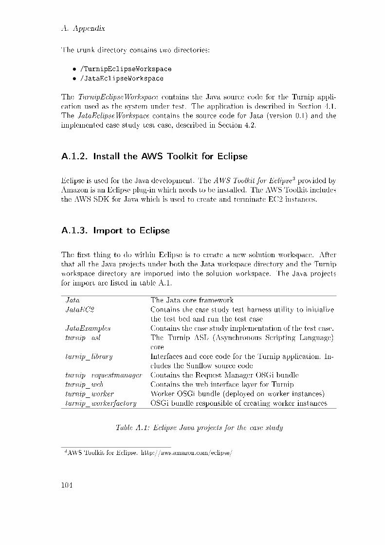
A. Appendix
The trunk directory contains two directories:
• /TurnipEclipseWorkspace
• /JataEclipseWorkspace
The TurnipEclipseWorkspace contains the Java source code for the Turnip appli-cation used as the system under test. The application is described in Section 4.1.The JataEclipseWorkspace contains the source code for Jata (version 0.1) and theimplemented case study test case, described in Section 4.2.
A.1.2. Install the AWS Toolkit for Eclipse
Eclipse is used for the Java development. The AWS Toolkit for Eclipse3 provided byAmazon is an Eclipse plug-in which needs to be installed. The AWS Toolkit includesthe AWS SDK for Java which is used to create and terminate EC2 instances.
A.1.3. Import to Eclipse
The �rst thing to do within Eclipse is to create a new solution workspace. Afterthat all the Java projects under both the Jata workspace directory and the Turnipworkspace directory are imported into the solution workspace. The Java projectsfor import are listed in table A.1.
Jata The Jata core frameworkJataEC2 Contains the case study test harness utility to initialize
the test bed and run the test caseJataExamples Contains the case study implementation of the test case.turnip_asl The Turnip ASL (Asynchronous Scripting Language)
coreturnip_library Interfaces and core code for the Turnip application. In-
cludes the Sun�ow source codeturnip_requestmanager Contains the Request Manager OSGi bundleturnip_web Contains the web interface layer for Turnipturnip_worker Worker OSGi bundle (deployed on worker instances)turnip_workerfactory OSGi bundle responsible of creating worker instances
Table A.1: Eclipse Java projects for the case study
3AWS Toolkit for Eclipse. http://aws.amazon.com/eclipse/
104

A.1. Development Environment Setup
A.1.4. Provide Amazon EC2 credentials
In order to run the test case within Amazon EC2 the Amazon AWS account cre-dentials need to be available to the startup process. This is done by including aproperties �les under the Turnip ASL Java project called AwsCredentials.properties.
• /turnip_asl/src/is/hi/turnip/cloud/aws/AwsCredentials.properties
The �le contains the two following credential properties shown in listing A.1.
1 secretKey=xxxxxxxxxxxxxxxxxxxxxxxxxxxxxxxxxxxxxxxx2 accessKey=xxxxxxxxxxxxxxxxxxxx
Listing A.1: Amazon AWS credential properties �le
A 40 character long secret key is needed and a 20 character access-key. The infor-mation can be found within the AWS Management Console4, under the SecurityCredentials menu.
A.1.5. Con�gure Amazon EC2 �rewall
Various TCP/IP ports need to be open within the cloud environment, both forthe Turnip application and the Jata test system. The ports for Turnip are HTTP,telnet, and Remote-OSGi ports. The telnet port is used by the Cloud-ASL forcommunicating with the Felix OSGi runtime. The HTTP port and the R-OSGiports are used by the Turnip application. The ports for the Jata test system areJava RMI ports used for the Jata remote ports and system ports communication.The TCP/IP ports are listed in table A.2. The cloud �rewall is con�gured withinthe Amazon AWS management console.
Port Description6666 Felix remote shell port (Telnet)9000 Turnip web application port (HTTP port)9279 Remote-OSGi port1291 Jata RMI remote port (PTC-1)1292 Jata RMI remote port (PTC-2)
Table A.2: Amazon EC2 Ports
4http://aws.amazon.com/console/
105

A. Appendix
A.1.6. Build and Package Turnip
The Turnip Java projects needs to be built and packaged as OSGi bundles. TheJava projects are built with ANT. All Turnip projects include an ANT build �lewhich builds the Java project code and packages them as an OSGi bundle. A masterbuild �le is provided under the turnip_library project. Project's individual ANTbuild �les are under each project's /resource directory. The master build �le is:
• /turnip_library/resources/build-main.xml
A.1.7. Upload Turnip Files to an HTTP Server
After building the Turnip bundles they need to be uploaded to an HTTP server,along with other dependencies. The Cloud-ASL uses HTTP download features forinstalling the bundles to the OSGi runtime server of the cloud instances when newinstances are started.
Currently no con�guration �le is used in Turnip so the HTTP server location is hard-wired into the ASL startup classes (is.hi.turnip.asl.groovy.ASLGroovy) for the mas-ter and (is.hi.turnip.workerfactory.impl.WorkerFactoryComponent) for the workers.The corresponding Java source �les are:
• /turnip_asl/src/is/hi/turnip/asl/groovy/ASLGroovy.java
• /turnip_workerfactory/src/is/hi/turnip/workerfactory/
impl/WorkerFactoryComponent.java
Listing A.2 shows the Java code that uses ASL startup procedure to launch theTurnip master node in the cloud (line 7 needs to be edited). Listing A.3 shows codefor the startup of Turnip workers (line 5 is the one that needs editing) As seen inthe listings not only the Turnip OSGi bundles need to be present but also OSGipackaged versions of dependent libraries. The dependent jars can be found underthe turnip_lib project's library folder:
• /turnip_library/lib/
The jar �les that are needed to be available on a HTTP server are the following:
1. jata-bar.jar2. turnip_asl.jar3. turnip_library.jar
106

A.1. Development Environment Setup
4. turnip_requestmanager.jar5. turnip_web.jar6. turnip_workerfactory.jar7. turnip_worker.jar8. aws-java-sdk-1.0.005.jar9. com.springsource.org.apache.commons.httpclient-3.1.0.jar10. org.apache.servicemix.bundles.jsch-0.1.42_2.jar11. jta26_bar.jar12. groovy-all-1.7.3.jar13. com.springsource.org.apache.commons.logging-1.1.1.jar14. com.springsource.org.apache.commons.codec-1.3.0.jar15. remote-1.0.0.RC4.jar16. jslp-osgi-1.0.0.RC5.jar
1 public Device start ( ) {2 DeviceImpl dev i ce = create_instance_dev ice ( "m1. smal l " ) ; // c r ea t e s
ec2 in s tance and s t a r t s Fe l i x on i t34 ASL a s l = new ASLImpl ( ) ;5 a s l . i n i t i a l i z e_d e v i c e ( dev i c e ) ;67 St r ing path = "http ://www. myserver . com/ turn ip /" ;89 insta l l_component ( device , path + " turn ip_as l . j a r " ) ;10 insta l l_component ( device , path + " turn ip_l ib ra ry . j a r " ) ;11 insta l l_component ( device , path + " turnip_requestmanager . j a r " ) ;12 insta l l_component ( device , path + "turnip_web . j a r " ) ;13 insta l l_component ( device , path + " turn ip_worker factory . j a r " ) ;14 insta l l_component ( device , path + "aws−java−sdk −1 .0 .005 . j a r " ) ;15 insta l l_component ( device , path + "com . sp r i ng sou r c e . org . apache . commons
. h t tp c l i e n t −3 . 1 . 0 . j a r " ) ;16 insta l l_component ( device , path + "org . apache . s e rv i c emix . bundles . j sch
−0.1 .42_2 . j a r " ) ;17 insta l l_component ( device , path + " jta26_bar . j a r " ) ;18 insta l l_component ( device , path + "groovy−a l l −1 . 7 . 3 . j a r " ) ;19 insta l l_component ( device , path + "com . sp r i ng sou r c e . org . apache . commons
. logg ing −1 . 1 . 1 . j a r " ) ;20 insta l l_component ( device , path + "com . sp r i ng sou r c e . org . apache . commons
. codec −1 . 3 . 0 . j a r " ) ;2122 start_components ( ) ;2324 return dev i c e ;25 }
Listing A.2: Java code for starting up the Turnip main node
107
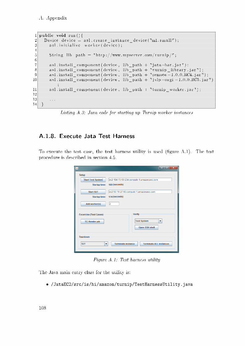
A. Appendix
1 public void run ( ) {2 Device dev i ce = a s l . c reate_instance_dev ice ( "m1. smal l " ) ;3 a s l . i n i t i a l i z e_wo rk e r ( dev i c e ) ;45 St r ing l ib_path = "http ://www. myserver . com/ turn ip /" ;67 a s l . instal l_component ( device , l ib_path + " jata−bar . j a r " ) ;8 a s l . instal l_component ( device , l ib_path + " turn ip_l ib ra ry . j a r " ) ;9 a s l . instal l_component ( device , l ib_path + "remote −1 . 0 . 0 .RC4. j a r " ) ;10 a s l . instal l_component ( device , l ib_path + " j s l p−osg i −1 . 0 . 0 .RC5. j a r " )
;11 a s l . instal l_component ( device , l ib_path + "turnip_worker . j a r " ) ;1213 . . .14 }
Listing A.3: Java code for starting up Turnip worker instances
A.1.8. Execute Jata Test Harness
To execute the test case, the test harness utility is used (�gure A.1). The testprocedure is described in section 4.5.
Figure A.1: Test harness utility
The Java main entry class for the utility is:
• /JataEC2/src/is/hi/amazon/turnip/TestHarnessUtility.java
108

A.2. Software Tools Used
A.2. Software Tools Used
Table A.3 lists the tools used in the development of the Jata test cases in this thesis.
Purpose ToolVersion control Subversion hosted at XP-Dev.comIDE Eclipse Java EE IDE for Web DevelopersTest framework Jata version 0.1OSGi BND tool Peter Kriens BND toolAmazon EC2 Firewall The AWS management consoleTest harness utility Custom made tool for the case study
Table A.3: Software used for the case study
A.3. Jata Test Cases source
The JataExamples project contains the source code for the Jata test cases. Themain Java package is:
• is.hi.jata.example.parametertestcase.turnip
This package contains code for the MTC, PTCs, the system adapter and the portsused in the test case. The test case class is:
• is.hi.jata.example.parametertestcase.turnip.ParameterTestCase
A.4. Jata Core Changes (if needed)
If changes are done to the core Jata library, it needs to be re-bundled as an OSGibundle.
The Jata source is automatically built with Eclipse. What needs to be done howeveris to export the Jata project from Eclipse as a Java jar �le. Furthermore theresulting jata.jar �le needs to be bound as an OSGi bundle. The worker instances
109

A. Appendix
(test double implementation) use the Jata core library for the remote ports so theJata jar is needed at the workers' OSGi runtime (Felix).
Peter Kriens BND tool5 can be run on the Jata jar �le to bundle it. The bnd.jar�le is under directory:
• /turnip_asl/resources/lib
The Java command line looks like:
java -jar bnd.jar wrap jata.jar
The output is an OSGi bundled version of the Jata library. Note! The �lename is'jata.bar' which needs to be renamed to 'jata-bar.jar'. This �le needs then tobe uploaded to the HTTP server for the Cloud-ASL to access it (as described inSection A.1.7).
5BND Tool. http://www.aqute.biz/Code/Bnd
110