distribution restriction statement · chemical guidelines for u.s. army corps of engineers ......
TRANSCRIPT

CEMP-RT/CECW-EG
Engineer Manual1110-1-4000
Department of the ArmyU.S. Army Corps of Engineers
Washington, DC 20314-1000
EM 1110-1-4000
1 November 1998
Engineering and Design
MONITORING WELL DESIGN,INSTALLATION, AND DOCUMENTATION
AT HAZARDOUS TOXIC, ANDRADIOACTIVE WASTE SITES
Distribution Restriction StatementApproved for public release; distribution is
unlimited.
_________________________________________________________________
EM 1110-1-4000 1 Nov 98
US Army Corpsof Engineers
ENGINEERING AND DESIGN
Monitoring Well Design,Installation, andDocumentation atHazardous, Toxic,and RadioactiveWaste Sites
This manual is approved for public release, distribution is unlimited.
ENGINEER MANUAL
AVAILABILITY
Electronic copies of this and other U.S. Army Corps of Engineers publications areavailable on the Internet at http://www.usace.army.mil/inet/usace-docs/. This site isthe only repository for all official USACE engineer regulations, circulars, manuals,and other documents originating from HQUSACE. Publications are provided inportable document format (PDF).
CEMP-RTCECW-EG
ManualNo. 1110-1-4000
DEPARTMENT OF THE ARMYU.S. Army Corps of EngineersWashington, DC 20314-1000
EM 1110-1-4000
1 November 1998
Engineering and DesignMONITORING WELL DESIGN, INSTALLATION, AND DOCUMENTATION
AT HAZARDOUS TOXIC, AND RADIOACTIVE WASTE SITES
1. Purpose. This Engineer Manual (EM) provides the minimum elements for consideration in thedesign, installation, and documentation of monitoring well placement (and other geotechnical activities)at projects known or suspected to contain chemically hazardous, toxic, and/or radioactive waste.
2. Applicability. This EM applies to all U.S. Army Corps of Engineers (USACE) commands havinghazardous, toxic, and radioactive waste (HTRW) project responsibilities. For special considerations ofradioactive, biological, or mixed (chemical and radioactive) waste components, contact the USACEHazardous, Toxic, and Radioactive Waste (HTRW) Center of Expertise (CX) in Omaha, Nebraska.
3. References. References are provided in Appendix A.
4. Distribution Statement. Approved for public release, distribution is unlimited.
5. Discussion. The technical understanding and evaluation of HTRW studies involves an apprecia-tion of the interactions between geology, hydrology, geotechnical engineering, and chemistry. Thisscenario is complicated by the trace (low parts per billion) levels of regulated chemical species that aredetectable in the environment and when detected or suspected may trigger intricate and costly responseactions. Slight deviations from prescribed drilling, well installation, sampling, or analytical proceduresmay bias or invalidate both the reported concentrations of these regulated species and the technical basisupon which the Corps makes decisions. These relationships are further complicated by the heteroge-neous, anisotropic character of the natural environment itself. This situation requires environmentalcharacterization based upon procedures that are standardized, documented, understood, and followed.This manual outlines that effort.
FOR THE COMMANDER:
2 AppendicesApp A - ReferencesApp B - Abbreviations
ALBERT J. GENETI, J R . Major General, USA
Chief of Staff
This manual supersedes EM 1110-1-4000, dated 31 August 1994.
i
DEPARTMENT OF THE ARMY EM 1110-1-4000U.S. Army Corps of Engineers
CEMP-RT Washington, DC 20314-1000
ManualNo. 1110-1-4000 1 November 1998
Engineering and DesignMONITORING WELL DESIGN, INSTALLATION, AND DOCUMENTATION AT
HAZARDOUS, TOXIC, AND RADIOACTIVE WASTE SITES
Table of Contents
Subject Paragraph PageChapter 1IntroductionPurpose ......................................................1-1 1-1Applicability..............................................1-2 1-1References .................................................1-3 1-1Terminology..............................................1-4 1-1Background ...............................................1-5 1-2
Chapter 2Boreholes and Wells: SiteReconnaissance, Locations,Quantities, and DesignationsSite Reconnaissance..................................2-1 2-1Locations and Quantities ..........................2-2 2-1Designations..............................................2-3 2-1
Chapter 3Drilling OperationsPhysical Security.......................................3-1 3-1Drilling Safety and Underground Utility Detection .....................................3-2 3-1Permits, Licenses, Professional Registration, and Rights-of-Entry ................................3-3 3-1Site Geologist ............................................3-4 3-1Equipment .................................................3-5 3-1Drilling Methods.......................................3-6 3-2Recirculation Tanks and Sumps...............3-7 3-8Materials ....................................................3-8 3-8Surface Runoff ..........................................3-9 3-14Drilling Through Contaminated Zones .......................................................3-10 3-14
Subject..............................................................
Soil Sampling............................................3-11 3-14Rock Coring ..............................................3-12 3-17Abandonment/Decommissioning.............3-13 3-18Work Area Restoration and Disposal of Drilling and Cleaning Residue...............3-14 3-19
Chapter 4Borehole LoggingGeneral ......................................................4-1 4-1Format........................................................4-2 4-1Submittal ...................................................4-3 4-1Original Logs and Diagrams ....................4-4 4-1Time of Recording....................................4-5 4-1Routine Entries..........................................4-6 4-1
Chapter 5Monitoring Well InstallationGeneral ......................................................5-1 5-1Well Clusters.............................................5-2 5-1Well Screen Usage....................................5-3 5-1Beginning Well Installation .....................5-4 5-1Screens, Casings, and Fittings ................5-5 5-5Granular Filter Pack..................................5-6 5-5Bentonite Seals..........................................5-7 5-6Grouting.....................................................5-8 5-6Well Protection .........................................5-9 5-7Shallow Wells ...........................................5-10 5-8Drilling Fluid Removal.............................5-11 5-11Drilling Fluid Losses in Bedrock.............5-12 5-11Well Construction Diagrams....................5-13 5-11
EM 1110-1-40001 Nov 98
ii
Subject Paragraph PageChapter 6Well DevelopmentGeneral ...................................................... 6-1 6-1Timing and Record Submittal.................. 6-2 6-1Development Methods ............................. 6-3 6-1Development Criteria ............................... 6-4 6-3Development-Sampling Break ................ 6-5 6-4Development Water Sample .................... 6-6 6-4Well Washing ........................................... 6-7 6-4Well Development Record ...................... 6-8 6-4Potential Difficulties ................................ 6-9 6-5
Chapter 7Well and Boring Acceptance CriteriaWell Criteria ............................................. 7-1 7-1Abandoned/Decommissioned Borings and Wells .................................. 7-2 7-1Well and Boring Rejection ...................... 7-3 7-1
Chapter 8Water LevelsMeasurement Frequency and Coverage .......................................... 8-1 8-1Vertical Control ........................................ 8-2 8-1Reporting and Usage................................ 8-3 8-1Methods..................................................... 8-4 8-1
Chapter 9Topographic SurveyLicensing................................................... 9-1 9-1Horizontal Control.................................... 9-2 9-1
Subject .............................................................. ParaVertical Control ........................................ 9-3 9-1Field Data.................................................. 9-4 9-1Geospatial Data Systems ......................... 9-5 9-1
Chapter 10Borehole GeophysicsUsage and Reporting................................ 10-1 10-1Methods..................................................... 10-2 10-1
Chapter 11Vadose Zone MonitoringUsage and Reporting................................ 11-1 11-1Methods..................................................... 11-2 11-1
Chapter 12Data Management SystemBenefits ..................................................... 12-1 12-1Assistance Sources ................................... 12-2 12-1Geospatial Data Systems ......................... 12-3 12-1
Appendix AReferences
Appendix BAbbreviations
List of Figures
Figure Page
3-1. Suggested format for use in obtaining water approval ......... ............ ............. 3-113-2. Suggested format for obtaining approval for filter pack....... ............ ............. 3-133-3. Example materials summary ............. ............ ............. ............. ............ ............. 3-16 4-1 Boring log fomat.................. ............. ............ ............. ............. ............ ............. 4-24-2. HTRW Drilling Log................. ............. ............ ............. ............. ............ ............. 4-55-1. Schematic construction of single-cased well with gravel blanket ... ............. 5-25-2. Schematic construction of multi-cased well with concrete pad ...... ............. 5-35-3. Schematic construction diagram of monitoring well............. ............ ............. 5-45-4. Post placement and gravel blanket layout around wells ...... ............ ............. 5-95-5. Schematic construction of flush-to-ground completion ....... ............ ............. 5-105-6. Well design parameters to minimize frost heave ..... ............. ............ ............. 5-11

EM 1110-1-40001 Nov 98
iii
List of Tables
Tables Page
3-1. Drilling Methods......... ....... ..... ............. ............ ............. .......................... .............3-34-1. Soil Parameters for Logging.. ............. ............ ............. .......................... .............4-74-2. Rock Core Parameters for Logging.... ............ ............. .......................... .............4-8
EM 1110-1-40001 Nov 98
1-1
Chapter 1Introduction
1-1. Purpose
This Engineer Manual (EM) provides geotechnical andchemical guidelines for U.S. Army Corps of Engineers(USACE) elements in the planning, installing, and reportingof soil and/or bedrock borings, monitoring wells, and othergeotechnical and geochemical devices at hazardous, toxic,and radioactive waste (HTRW) sites. These guidelines are acompilation of those procedures necessary for theacquisition of environmentally representative geotechnicaldata and samples, using conservative methods documentedin a comprehensive manner.
1-2. Applicability
a. This EM applies to all USACE commands, elementsand their contractors (including architect-engineers, [AE's])having military and/or civil works hazardous, toxic andradioactive waste (HTRW) site responsibilities and/orengaged in programs within the ComprehensiveEnvironmental Resource, Compensation, and Liability Act(CERCLA); the Resource Conservation and Recovery Act(RCRA); the Superfund Amendments and ReauthorizationAct (SARA); the Defense Environmental RestorationProgram (DERP); non-mission HTRW work for other (non-Corps) offices; work within host nation agreements; or anyother Corps-managed HTRW activities.
b. Only HTRW work involving chemical issues arecovered within this manual. Biological waste components ofHTRW are not addressed. Supplemental instructions will beprovided as appropriate procedures are identified. In theinterim, any requests for assistance in those areas should bedirected to the Hazardous, Toxic, and Radioactive Waste(HTRW) Center of Expertise (CX) within the U.S. ArmyEngineer District, Omaha (CENWO), Attention: HTRW -Center of Expertise, Geoenvironmental & ProcessEngineering Branch (CENWO-HX-G); or Headquarters,U.S. Army Corps of Engineers (HQUSACE), Attention:Directorate of Military Programs, Policy and TechnologyBranch (CEMP-RT).
c. The specific application of and adherence to theseguidelines must be tailored to each project as a function ofthe contaminants of concern; local geohydrologic
setting; geotechnical judgment; available resources;applicable regulatory requirements; policy and guidance;public concerns; and project mission.
1-3. References
Appendix A contains a list of those publications referencedby and relevant to this manual.
1-4. Terminology
a. General. As in any relatively new field using theprinciples, terminology, and personnel of several otherfields, there is a certain lack of communication over thelanguage used to express data and mechanisms within thisnew field. The situation is further compounded by alterna-tive methods, both traditional and innovative, to completeactual projects. The additional requirements for permits,licenses, and other federal and state regulatory procedures,and the potential for litigation, add to the HTRW sitecomplexities.
b. Corps situation.
(1) Within USACE, a given HTRW project may beperformed totally in-house, partially in-house, or by one ormore contractors/AE's (either independently reporting to theCorps or through a system of prime- and subcontracting).One Corps office may broker the work of another who inturn contracts the effort. In some cases, one Corps districtmay design a project and award the contract while a seconddistrict supervises construction.
(2) Providing program level technical guidance in thisadministrative situation requires the guidance to be specific,while allowing any field activity to adapt the guidance to itsneeds. The intent is to foster the defense of variances, notthe defense of recommended methods and procedures. Thisapproach is warranted to provide the Corps withcompatibility and continuity of HTRW investigations whileallowing functional flexibility. With this in mind, thefollowing three terms are introduced: the field activity (FA);the field drilling organization (FDO); and the drilling andwell installation plan. These terms are defined in paragraphs1-4c(2), (3), and (1), respectively. Generically, these termsrefer to a client-contractor-contract relationship. Thisrelationship can be applied to both in-house and contractedefforts, thereby providing consistency for the geotechnicalportion of the Corps HTRW involvements.
EM 1110-1-40001 Nov 98
1-2
c. Definitions (alphabetically arranged). These defi-nitions are intended to guide the reader through the use ofthis manual. While other terms with equivalent definitionsmay be familiar to some readers, the terminology as definedhere provides a common basis for the CONSISTENTunderstanding by ALL readers.
(1) Field Sampling Plan (FSP). The FSP is containedwithin the Sampling and Analysis Plan (SAP), and describesthe drilling and well installation plan. The SAP and FSPrequirements are outlined in EM 200-1-3. The FSP isapproved by the FA or FDO before field activities begin.The plan specifies the particulars of the field effort; forexample: borehole/well/sample locations, depths, equipment,materials, procedures and alternatives, quality controlmeasures, and other topics required by the responsible FA.Implementation is by the FDO.
(2) Field activity (FA). That Corps element minimallyheaded by a Commander or Director; e.g., district, labora-tory, or agency, assigned or otherwise acquiring theresponsibility to administer a contract, agreement, orin-house Corps procedure to research, investigate, design,and/or construct a project involving hazardous and/or toxicwastes.
(3) Field drilling organization (FDO). That officewithin the Corps or contracted by the Corps responsible forexecution of the drilling plan. In a contracted arrangement,the prime contractor is regarded as the FDO. Sub-contractors, even though they may physically perform thefield work, are the responsibility of the prime contractor,whom the Corps holds contractually accountable.
(4) Geotechnical data quality management (GDQM).The development and application of those policies andprocedures required to obtain and utilize accurate andrepresentative geotechnical information throughout theentire HTRW project cycle, from predesign investigations topostconstruction monitoring.
(5) Hazardous, toxic, and radioactive waste (HTRW). AUSACE idiom referring to substances which because of theirproperties, occurrence, or concentration, may potentiallypose a threat to human health and welfare, or to theenvironment. This includes materials defined by federalregulations as hazardous waste, hazardous substances, andpollutants.
(6) Monitoring well. A monitoring well is a devicedesigned and constructed for the acquisition of groundwatersamples that are representative of the chemical quality of theaquifer adjacent to the screened interval, unbiased by the
well materials and installation process; and which, if sodesigned, provides access to measure potentiometric headacross the screened interval.
(7) Redevelopment/well rehabilitation. A procedurewhich restores the original or near original pumping capacityto an existing well by the removal of sediment, precipitation,flocculent, surface run-in, or other built-up materials fromwithin that well.
(8) Screened interval. That portion of a well which isdirectly open to the host environment/aquifer by way ofopenings in the well screen.
(9) Site safety and health plan (SSHP). A project-unique document approved by the responsible FA for FDOcompliance. The plan includes the identification of hazardoussubstances present, recommended action upon encounteringthose substances, project/site safety requirements,organizational safety responsibilities, and the identificationof supporting health and safety activities.
(10) Well development. A procedure which locallyimproves or restores the aquifer's hydraulic conductivity,well capacity, and removes well drilling fluids, muds,cuttings, mobile particulates, and entrapped gases fromwithin and adjacent to a newly installed well.
d. Acronyms. Appendix B contains a list of theabbreviations used in this manual.
1-5. Background
a. EM 1110-1-4000. As a GDQM mechanism, thismanual provides guidance for collection and documentationof geotechnical information. Site-specific deviations shouldbe described and supported in the drilling and wellinstallation plan.
(1) Technical understanding and evaluation of HTRWstudies involve an appreciation of the interactions amongmany fields including geology, hydrology, geotechnicalengineering, and chemistry. This scenario is complicated bythe trace (low parts per billion) levels of regulated chemicalspecies that are detectable in the environment and which,when detected or suspected, trigger intricate and costlyresponse actions. Slight deviations from prescribed drilling,well installation, sampling, or analytical procedures maybias or invalidate the reported concentrations. Thissensitivity requires that procedures be relevant, standardized,documented, understood, and followed. Despite theseprocedures, the normal heterogeneity and anisotropy ofnatural field occurrences are, in themselves, frequentlysufficient to confuse the appropriate interpretation of the
EM 1110-1-40001 Nov 98
1-3
gathered field data.
(2) The specific content of this manual will be peri-odically updated based upon reader suggestions, lessonslearned, technological advances, and Corps needs. Issues ofsignificant concern will be disseminated Corpswide in amore expeditious manner.
(3) Not all geotechnical personnel will agree on everypractice advocated herein. Any such variations should beover a matter of degree, not substance. If the readerperceives a technical difficulty in any of this manual'scontents, the reader is requested to contact the proponent.
b. Proponency. The technical proponents for this manualare the Policy and Technology Branch, EnvironmentalDivision, Directorate of Military Programs (CEMP-R), andthe Geotechnical and Materials Branch, EngineeringDivision, Directorate of Civil Works (CECW-EG),Headquarters, U.S. Army Corps of Engineers. All commentsand suggestions should be directed to HQUSACE, CEMP-R,20 Massachusetts Avenue, N.W., Washington, D.C. 20314-1000.
EM 1110-1-40001 Nov 98
2-1
Chapter 2Boreholes and Wells:Site Reconnaissance, Locations,Quantities, and Designations
2-1. Site Reconnaissance
Site visits are suggested for project geotechnical personnel asearly as practical in the planning for any subsurfaceexploration. The purpose of this reconnaissance is to evaluatephysical site conditions and logistical support availability.Particular items of interest would include geologic andgeographic settings, site access, proximal utilities, serviceareas, sample shipment facilities, and potential hazards. Application of this knowledge will contribute to enhancingthe technical approach and cost realism for subsequent projectdevelopment.
2-2. Locations and Quantities
The locations and quantities of boreholes and wells should beselected to effectively ascertain desired geologic, hydrologic,and/or chemical parameters. The number of borings or wellsspecified in the drilling plan should not be altered withoutcoordination with the FA. The drilling and well installationplan should permit relocations when necessitated by proximalutilities or drilling difficulties. The criteria for selection of thenew location(s) should be included as a portion of the drillingplan and should indicate when coordination would be requiredwith the FA.
2-3. Designations
Borehole and well designations (identification numbers)should not be unilaterally changed in the field or in a cen-tralized computer database without prior approval of theinstalling Corps organization or non-Corps agency. Afterreceiving approval, the requesting FA should physically re-number those sites where a designation is posted in the field. Temporary conversions not involving the alteration of eitherfield markings or a centralized database may be done forreporting purposes without approval of the installing organi-zation or agency. Such temporary changes may be necessary,for instance, if the data entry format of a given computersystem is not compatible with the characters in the existingwell designation. A conversion table should be included in thefinal report to document any permanent or temporaryboring/well designation changes.
EM 1110-1-40001 Nov 98
3-1
Chapter 3Drilling Operations
3-1. Physical Security
The FDO should comply with all security policies at the projectsite. The FDO is responsible for securing its own equipment.The FDO should address any special situations in the drillingplan.
3-2. Drilling Safety and UndergroundUtility Detection
When drilling in areas of known or suspected hazardousmaterials, appropriate health and safety precautions should beimplemented. Guidance adaptable for drilling activities isavailable in Occupational Safety and Health Administration(OSHA) documents (particularly, 29 CFR 1910.120 and 29CFR 1926), ER 385-1-92, and EM 385-1-1. The FDO shoulddetermine all applicable regulations, requirements, and permitswith regard to drilling safety and underground utility detection.These items should be included in the safety plan. The safetyplan should be approved by the FA prior to any drilling.
3-3. Permits, Licenses, ProfessionalRegistration, and Rights-of-Entry
The FA should be responsible for identifying all applicablepermits, licenses, professional registration, rights-of-entry, andapplicable state and local regulatory procedures for drilling,well installation, well decommissioning/ abandonment, andtopographic surveying (to include any requirements for thesubmission of well logs, samples, etc.). Acquisition andsubmission of these items to state or local authorities should becoordinated between the FA and FDO, with the responsibilitiesof each specified in the drilling plan. The need for any rights-of-entry should be specified in the drilling plan along with theorganization(s) responsible for their acquisition.
3-4. Site Geologist
A “site geologist” (defined as an earth science or engineeringprofessional with a college degree in geology, civil engineering,or related field; experienced in HTRW projects, soil and rocklogging, and monitoring well installation), should be present ateach operating drill rig. This geologist should be responsiblefor logging; acquisitioning (and possibly shipment) of samples;monitoring of drilling operations; recording of waterlosses/gains and groundwater data; preparing the boring logsand well diagrams; and recording the well installation anddecommissioning procedures conducted with that rig. Each sitegeologist should be responsible for only one operating rig. Thegeologist should have onsite sufficient tools, forms, and
professional equipment in operable condition to efficientlyperform the duties as outlined in this manual and otherrelevant project documents. Items in the possession of eachsite geologist should include, as a minimum, a copy of thismanual, a copy of the approved drilling and well installationplan, log forms, the approved safety plan, a 10-power(minimum) hand lens, and a measuring tape (weighted withstainless steel or chemically stable, nonmetallic material)long enough to measure the deepest boring/well within theproject, heavy enough to reach that depth, and small enoughto readily fit within the appropriate annulus or opening.Each site geologist should also have onsite a water-levelmeasuring device (preferably electrical), pH and electricconductivity meters, a turbidimeter, a thermometer, aninstrument for measuring dissolved oxygen, and materialsnecessary to prepare the samples for storage or shipment. Atsome sites, the geologist may be also responsible formonitoring gases during drilling. If so, the geologist shouldhave the necessary instruments and be proficient in their useand calibration.
3-5. Equipment
a. Condition. All drilling, sampling, and supportingequipment brought to a site should be in operable conditionand free of leaks in the hydraulic, lubrication, fuel, and otherfluid systems where fluid leakage would or could bedetrimental to the project effort. All switches (to includesafety switches), gages, and other electrical, mechanical,pneumatic, and hydraulic systems should be in a safe andoperable condition prior to arrival onsite.
b. Cleaning. All drilling equipment should be cleanedwith steam or pressurized hot water before arriving at theproject installation/site. After arrival but prior to projectcommencement, all drilling equipment including rigs,support vehicles, water tanks (inside and out), augers, drillcasings, rods, samplers, tools, recirculation tanks, etc.,should be cleaned with steam or pressurized hot water usingapproved water (see paragraph 3-9b) at the installationdecontamination point. Guidance for decontamination offield equipment may be found in ASTM D 5088. Samplersand other equipment, such as water level indicators,oil/water interface probes, etc. may require additionaldecontamination steps. A similar cleaning should also occurbetween each boring/well site. After the onsite cleaning,only the equipment used or soiled at a particular boring orwell should need to be recleaned between sites. Unlesscircumstances require otherwise, water tank interiors maynot need to be cleaned between each boring/well at a givenproject. Prior to use, all casings, augers, recirculation andwater tanks, etc., should be devoid both inside and out ofany asphaltic, bituminous, or other encrusting or coatingmaterials, grease, grout, soil, etc. Paint, applied by theequipment manufacturer, may not have to be removed from
EM 1110-1-40001 Nov 98
3-2
drilling equipment, depending upon the paint composition andits contact with the environment and contaminants of concern.All equipment should be decontaminated before it is removedfrom the project site. If drilling requires telescoping casingbecause of differing levels of contamination in subsurfacestrata, then decontamination may be necessary before settingeach string of smaller casing and before drilling beyond anycasing. To the extent practical, all cleaning should beperformed in a single remote area that is surficiallycrossgradient or downgradient from any site to be sampled.Waste solids and water from the cleaning/decontaminationprocess should be properly collected and disposed. This mayrequire that cleaning be conducted on a concrete pad or othersurface from which the waste materials may be collected.Guidance for decontamination of field equipment used at lowlevel radioactive waste sites may be found in ASTM D 5608.
3-6. Drilling Methods
a. Objective. The objective of selecting a drillingmethod for monitor well installation is to use that techniquewhich
(1) Provides representative data and samples.
(2) Eliminates or minimizes the potential for subsurfacecontamination and/or cross-contamination.
(3) Minimizes drilling costs.
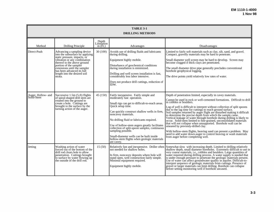
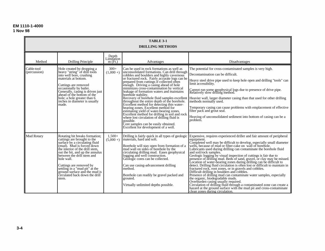
b. Methods. Table 3-1 presents types of drillingmethods. Detailed descriptions of different drilling methodsmay be found in EPA/600/4-89/034, EPA/625/R-93/003a,USGS WRI Report 96-4233, USGS TWRI Book 2 Chapter F1,ASTM D 6286, Driscoll (1986), and U.S. Army FM 5-484.Where possible, ASTM drilling method-specific guides arereferenced with the drilling methods listed below.
(1) Hollow stem augers. Method references: ASTM D 5784and EPA/600/4-89/034.
(2) Cable tool/churn drill. Method reference: ASTM D5875.
(3) Water/mud rotary. Method references: ASTM D5781, D 5783, and D 5876.
(4) Air/pneumatic rotary methods. Method reference: D5782.
(5) Sonic/vibratory. Method reference: EPA/625/R-94/003.
(6) Direct Push. Method references: ASTM StandardGuides D 6001 and D 6282, and EPA/510/B-97/001.
c. Special concerns.
(1) Dry methods.
(a) Hollow stem augers are technically advantageous inmost situations because of their “dry” method of drilling. Adry drilling method is preferred for HTRW work. Drymethods advance a boring using purely mechanical meanswithout the aid of an aqueous or pneumatic drilling “fluid”for cuttings removal, bit cooling, or borehole stabilization.In this way, the chemical interface with the subsurface isminimized, though not eliminated. Local aeration of theborehole wall, for example, may occur simply by theremoval of compacted or confining soil or rock.
(b) Vibratory, or sonic drilling, employs the use of high-frequency mechanical vibration to take continuous coresamples of overburden soils and most hard rock. A sonicdrill rig uses an oscillator, or head, with eccentric weightsdriven by hydraulic motors, to generate high sinusoidalforce in a rotating drill pipe. The frequency of vibration ofthe drill bit or core barrel can be varied to allow optimumpenetration of subsurface materials. Sonic drillingpenetrates a formation by displacement, shearing, orfracturing. Displacement occurs by fluidizing the soilparticles (sands and light gravels) and causing them to moveeither into the formation or into the center of the drill pipe.Shearing occurs in dense silts, clays, and shales, if the axialoscillations of the drill pipe overcomes the elastic nature ofthe material. The penetration of cobbles, boulders, and rockis caused by fracturing of the material by the inertial momentof the drill bit. Although, rock drilling and sampling requiresthe addition of water or air to remove drill cuttings, thevolume of drill cuttings generated during sonic drilling isusually much less than those generated from some otherdrilling methods. Drilling through unconsolidated materialcan be done in the dry, without the use of drilling fluidssuch as air or water-based fluids and additivies. Overall, thesonic drilling method can also offer the advantages ofobtaining relatively undisturbed soil and rock samples athigher drilling rates than conventional methods, with highpercentage of core recovery, and produces lessinvestigation-derived waste.
3-3
EM 1110-1-40001 Nov 98
TABLE 3-1
DRILLING METHODS
Method Drilling Principle
DepthLimitation
m (Ft.) Advantages Disadvantages
Direct-Push Advancing a sampling deviceinto the subsurface by applyingstatic pressure, impacts, orvibration or any combinationthereof to the above groundportion of the samplerextensions until the samplerhas been advanced its fulllength into the desired soilstrata.
30 (100) Avoids use of drilling fluids and lubricantsduring drilling.
Equipment highly mobile.
Disturbance of geochemical conditionsduring installation is minimized.
Drilling and well screen installation is fast,considerably less labor intensive.
Does not produce drill cuttings, reduction of IDW.
Limited to fairly soft materials such as clay, silt, sand, and gravel. Compact, gravelly materials may be hard to penetrate.
Small diameter well screen may be hard to develop. Screen maybecome clogged if thick clays are penetrated.
The small diameter drive pipe generally precludes conventionalborehole geophysical logging.
The drive points yield relatively low rates of water.
Auger, Hollow- andSolid-Stem
Successive 1.5m (5-ft) flightsof spiral-shaped drill stem arerotated into the ground tocreate a hole. Cuttings arebrought to the surface by theturning action of the auger.
45 (150) Fairly inexpensive. Fairly simple andmoderately fast operation.
Small rigs can get to difficult-to-reach areas. Quick setup time.
Can quickly construct shallow wells in firm,noncavey materials.
No drilling fluid or lubricants required.
Use of hollow-stem augers greatly facilitatescollection of split-spoon samples, continuoussampling possible.
Small-diameter wells can be built insidehollow-stem flights when geologic materialsare cavey.
Depth of penetration limited, especially in cavey materials.
Cannot be used in rock or well-cemented formations. Difficult to drillin cobbles or boulders.
Log of well is difficult to interpret without collection of split spoonsdue to the lag time for cuttings to reach ground surface.Soil samples returned by auger flight are disturbed making it difficultto determine the precise depth from which the sample came. Vertical leakage of water through borehole during drilling is likely tooccur. Solid-stem limited to fine-grained, unconsolidated materialsthat will not collapse when unsupported. Borehole wall can besmeared by previosly-drilled clay.
With hollow-stem flights, heaving sand can present a problem. Mayneed to add water down-auger to control heaving or wash materialsfrom auger before completing well.
Jetting Washing action of waterforced out of the bottom of thedrill rod clears hole to allowpenetration. Cuttings broughtto surface by water flowing upthe outside of the drill rod.
15 (50) Relatively fast and inexpensive. Driller oftennot needed for shallow holes.
In firm, noncavey deposits where hole willstand open, well construction fairly simple.Minimul equipment required.
Equipment highly mobile.
Somewhat slow with increasing depth. Limited to drilling relativelyshallow depth, small diameter boreholes. Extremely difficult to use invery coarse materials, i.e., cobbles and boulders. Large quantities ofwater required during drilling process. A water supply is needed thatis under enough pressure to penetrate the geologic materials present.Use of water can affect groundwater quality in aquifer. Difficult-to-interpret sequence of geologic materials from cuttings. Presence ofgravel or larger materials can limit drilling. Borehole can collapsebefore setting monitoring well if borehole uncased.
EM 1110-1-40001 Nov 98
TABLE 3-1
DRILLING METHODS
Method Drilling Principle
DepthLimitation
m (Ft.) Advantages Disadvantages
3-4
Cable-tool(percussion)
Hole created by dropping aheavy "string" of drill toolsinto well bore, crushingmaterials at bottom.
Cuttings are removedoccasionally by bailer. Generally, casing is driven justahead of the bottom of thehole; a hole greater than 6inches in diameter is usuallymade.
300+(1,000 +)
Can be used in rock formations as well asunconsolidated formations. Can drill throughcobbles and boulders and highly cavernousor fractured rock. Fairly accurate logs can beprepared from cuttings if collected oftenenough. Driving a casing ahead of holeminimizes cross-contamination by verticalleakage of formation waters and maintainsborehole stability.Recovery of borehole fluid samples excellentthroughout the entire depth of the borehole.Excellent method for detecting thin water-bearing zones. Excellent method forestimating yield of water-bearing zones.Excellent method for drilling in soil and rockwhere lost circulation of drilling fluid ispossible. Core samples can be easily obtained.Excellent for development of a well.
The potential for cross-contaminated samples is very high.
Decontamination can be difficult.
Heavy steel drive pipe used to keep hole open and drilling "tools" canlimit accessibility.
Cannot run some geophysical logs due to presence of drive pipe. Relatively slow drilling method.
Heavier wall, larger diameter casing than that used for other drillingmethods normally used.
Temporary casing can cause problems with emplacement of effectivefilter pack and grout seal.
Heaving of unconsolidated sediment into bottom of casing can be aproblem.
Mud Rotary Rotating bit breaks formation;cuttings are brought to thesurface by a circulating fluid(mud). Mud is forced downthe interior of the drill stem,out the bit, and up the annulusbetween the drill stem andhole wall.
Cuttings are removed bysettling in a "mud pit" at theground surface and the mud iscirculated back down the drillstem.
1,500+(5,000 +)
Drilling is fairly quick in all types of geologicmaterials, hard and soft.
Borehole will stay open from formation of amud wall on sides of borehole by thecirculating drilling mud. Eases geophysicallogging and well construction. Geologic cores can be collected.
Can use casing-advancement drillingmethod.
Borehole can readily be gravel packed andgrouted.
Virtually unlimited depths possible.
Expensive, requires experienced driller and fair amount of peripheralequipment.Completed well may be difficult to develop, especially small diameterwells, because of mud or filter-cake on wall of borehole.Lubricants used during drilling can contaminate the borehole fluidand soil/rock samples.Geologic logging by visual inspection of cuttings is fair due topresence of drilling mud. Beds of sand, gravel, or clay may be missed.Location of water-bearing zones during drilling can be difficult todetect. Drilling fluid circulation is often lost or difficult to maintain infractured rock, root zones, or in gravels and cobbles.Difficult drilling in boulders and cobbles.Presence of drilling mud can contaminate water samples, especiallythe organic, biodegradable muds.Overburden casing usually required.Circulation of drilling fluid through a contaminated zone can create ahazard at the ground surface with the mud pit and cross-contaminateclean zones during circulation.
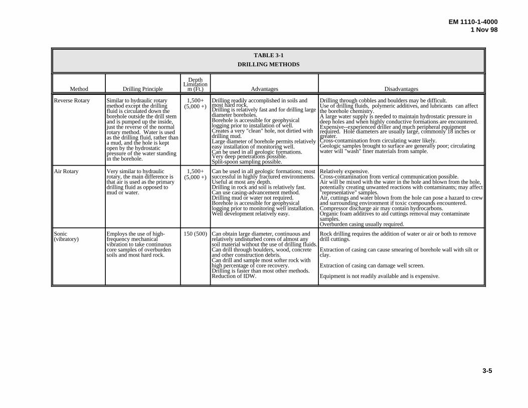
TABLE 3-1
DRILLING METHODS
Method Drilling Principle
DepthLimitation
m (Ft.) Advantages Disadvantages
3-5
EM 1110-1-40001 Nov 98
Reverse Rotary Similar to hydraulic rotarymethod except the drillingfluid is circulated down theborehole outside the drill stemand is pumped up the inside,just the reverse of the normalrotary method. Water is usedas the drilling fluid, rather thana mud, and the hole is keptopen by the hydrostaticpressure of the water standingin the borehole.
1,500+(5,000 +)
Drilling readily accomplished in soils andmost hard rock.Drilling is relatively fast and for drilling largediameter boreholes.Borehole is accessible for geophysicallogging prior to installation of well.Creates a very "clean" hole, not dirtied withdrilling mud.Large diameter of borehole permits relativelyeasy installation of monitoring well. Can be used in all geologic formations.Very deep penetrations possible. Split-spoon sampling possible.
Drilling through cobbles and boulders may be difficult. Use of drilling fluids, polymeric additives, and lubricants can affectthe borehole chemistry. A large water supply is needed to maintain hydrostatic pressure indeep holes and when highly conductive formations are encountered.Expensive--experienced driller and much peripheral equipmentrequired. Hole diameters are usually large, commonly 18 inches orgreater.Cross-contamination from circulating water likely. Geologic samples brought to surface are generally poor; circulatingwater will "wash" finer materials from sample.
Air Rotary Very similar to hydraulicrotary, the main difference isthat air is used as the primarydrilling fluid as opposed tomud or water.
1,500+(5,000 +)
Can be used in all geologic formations; mostsuccessful in highly fractured environments.Useful at most any depth.Drilling in rock and soil is relatively fast.Can use casing-advancement method.Drilling mud or water not required.Borehole is accessible for geophysicallogging prior to monitoring well installation. Well development relatively easy.
Relatively expensive.Cross-contamination from vertical communication possible.Air will be mixed with the water in the hole and blown from the hole,potentially creating unwanted reactions with contaminants; may affect"representative" samples. Air, cuttings and water blown from the hole can pose a hazard to crewand surrounding environment if toxic compounds encountered.Compressor discharge air may contain hydrocarbons.Organic foam additives to aid cuttings removal may contaminatesamples.Overburden casing usually required.
Sonic(vibratory)
Employs the use of high-frequency mechanical vibration to take continuouscore samples of overburdensoils and most hard rock.
150 (500) Can obtain large diameter, continuous andrelatively undisturbed cores of almost anysoil material without the use of drilling fluids. Can drill through boulders, wood, concreteand other construction debris.Can drill and sample most softer rock withhigh percentage of core recovery.Drilling is faster than most other methods.Reduction of IDW.
Rock drilling requires the addition of water or air or both to removedrill cuttings.
Extraction of casing can cause smearing of borehole wall with silt orclay.
Extraction of casing can damage well screen.
Equipment is not readily available and is expensive.
EM 1110-1-40001 Nov 98
TABLE 3-1
DRILLING METHODS
Method Drilling Principle
DepthLimitation
m (Ft.) Advantages Disadvantages
3-6
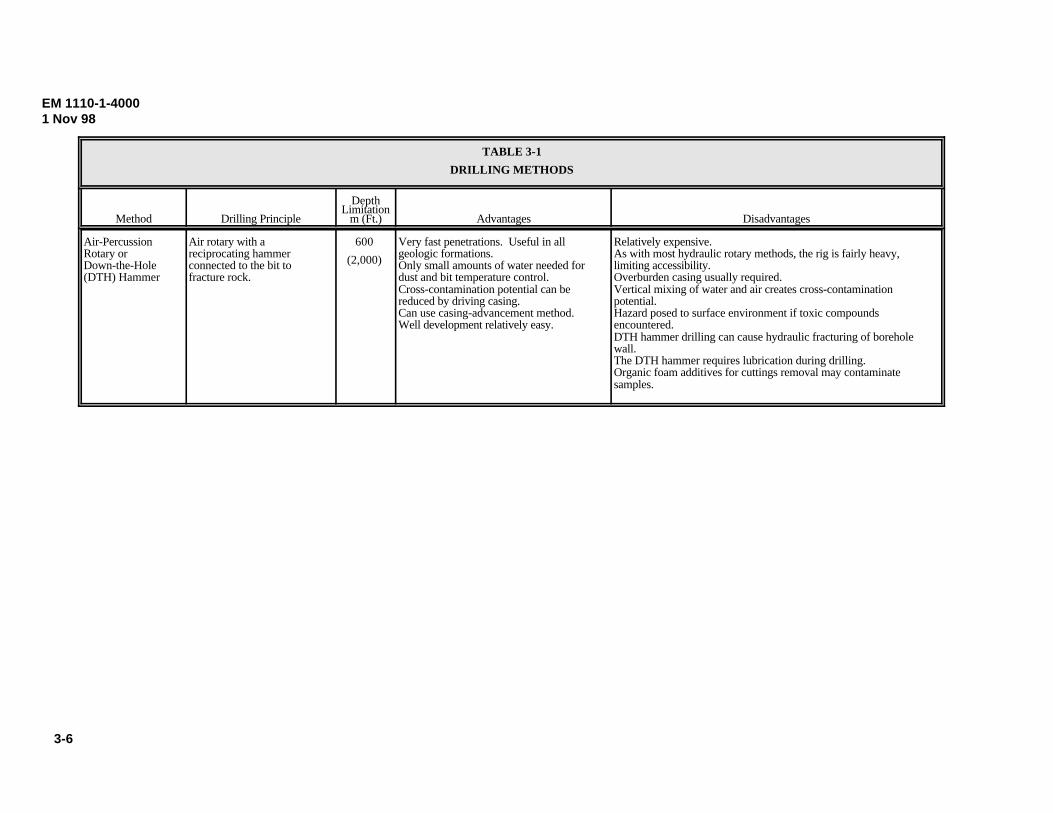
Air-Percussion Rotary or Down-the-Hole (DTH) Hammer
Air rotary with a reciprocating hammer connected to the bit to fracture rock.
600
(2,000)
Very fast penetrations. Useful in all geologic formations.Only small amounts of water needed for dust and bit temperature control. Cross-contamination potential can be reduced by driving casing.Can use casing-advancement method. Well development relatively easy.
Relatively expensive. As with most hydraulic rotary methods, the rig is fairly heavy, limiting accessibility.Overburden casing usually required. Vertical mixing of water and air creates cross-contamination potential. Hazard posed to surface environment if toxic compounds encountered. DTH hammer drilling can cause hydraulic fracturing of borehole wall.The DTH hammer requires lubrication during drilling.Organic foam additives for cuttings removal may contaminate samples.
EM 1110-1-40001 Nov 98
3-7
(c) Another dry method, known as the direct pushmethod, involves sampling devices that are directlyinserted into the soil to be sampled without drilling orborehole excavation. Direct push sampling also includesthe use of the Site Characterization and AnalysisPenetrometer System (SCAPS) which has contaminantscreening capability in addition to indirect soilstratigraphy information (ASTM D 5778 and D 6067).Direct push sampling consists of advancing a samplingdevice into the subsurface by applying static pressure,impacts, or vibration or any combination thereof to theabove ground portion of the sampler extensions until thesampler has been advanced its full length into the desiredsoil strata. Direct push methods may be used to collectboth soil (ASTM D 6282) and water samples (ASTM D6001). In some cases the method may combine watersampling and/or vapor sampling with soil sampling in thesame investigation. The direct push sampling method iswidely used as a preliminary site characterization tool forthe initial field activity of a site investigation. Direct pushsampling is an economical and efficient method forobtaining descrete soil and water samples without theexpense of drilling and its related decontamination andwaste cuttings disposal costs. This method may beespecially advantageous at a radioactive site, where thereduction of IDW is of special importance. The equipmentgenerally used in direct push sampling is small andrelatively compact allowing for better mobility around thesite and access to confined areas. The rapid samplegathering provided by direct push methods can be used todetermine the chemical composition of the soils andground water in the field in certain circumtances. Thismethod may offer an immediate determination of the needfor further monitoring points. It must be cautioned,however, that certain temporary well points installed bythis method may not be allowed as permanent monitoringwells by some state and local regulations.
(2) Pneumatic methods. When air is used itshould be detailed in the drilling plan, to include thefollowing items:
(a) Situation favoring air usage.
(b) Air drilling method to be used.
(c) Expected subsurface contaminants, and howfield personnel will be protected from any adverse effectscaused by these contaminants in the returned air andparticles blown from the borehole or well.
(d) The potential effects of air usage upon thechemical analyses of groundwater and soil (especially for
volatile species) and the mitigation procedures to negatethe detrimental aspects of these effects.
(e) The potential effects of air usage upon thephysical, hydrological, and structural character of thesurrounding soil and/or rock and the mitigation to addressthe negative aspects of these effects.
(f) Measures to be taken to reduce oil usage and tolimit aquifer aeration.
(g) Specify the type of air compressor andcompressor lubricating oil and require that sufficientsamples of the initial reservoir (and any refill) oil beretained by the FDO, along with a record of oil loss(recorded on the boring log), for evaluation in the event offuture problems. The oil sample(s) may be disposed ofupon project completion.
(h) Require an air line oil filter and that the filterbe changed per manufacturer's recommendation duringoperation with a record kept (on the boring log) of thismaintenance. More frequent changes should be made ifoil is visibly detected in the filtered air, as by an oil stainon clean, writing paper after directing the filteredair from a hose onto the paper “300 mm” (“a foot”) awayfor “15 seconds.” (While these numbers are arbitrary,they are provided as examples for FDO guidance andintra/interproject consistency.)
(i) Prohibit the use of any additive exceptapproved water for dust control and cuttings removal.
(j) Detail the use of any downhole hammer/bitwith emphasis upon those procedures to be taken topreclude residual groundwater sample contaminationcaused by the lubrication of the downhole equipment.
(k) Discuss the volume of air and pressure ratingrequired for drilling and whether a downhole hammer,rotary bit, or both can be used. The air volume and pres-sure required should be adequate for the hole diameter,boring depth, available equipment, and site conditions.
(l) Detail the use of any bottled gas with emphasison air composition, quality, quantity, method of bottling,and anticipated use.
EM 1110-1-40001 Nov 98
3-8
(m) Air usage should be fully described in theboring log to include equipment description(s), manu-facturer(s), model(s), air pressures used, frequency of oilfilter change, and evaluation of the system performance,both design and actual.
(3) Aqueous methods.
(a) Aqueous drilling methods use a fluid, usuallywater, or a water and bentonite mix, for cuttings removal,bit cooling, and hole stabilization. For HTRW work, theuse of these materials increases the potential to add a newcontaminant or suite of contaminants to the subsurfaceenvironment adjacent to the boring. Even the removal ofone or more volumes of water equal to that which was lostduring drilling will not remove all of the lost fluid. Inaddition, the level of effort to be expended upon welldevelopment is directly tied to the amount of water lossduring drilling: a minimum of three times the volume lostto be removed during development. Therefore, the lessfluid loss, the less the development effort (time and cost).
(b) The situation is further complicated whenbentonite is used. While bentonite tends to reduce theamount of drilling fluid loss, the residual bentoniteremaining around the boring after development may pro-vide sufficient sorptive material to modify local ground-water chemistry for some parameters (for example,metals).
3-7. Recirculation Tanks and Sumps
If possible, only portable recirculation tanks should beused for mud/water rotary operations and similarfunctions. The use of dug sumps or pits (lined) should beused only if necessary, as when the volume necessary tohandle problem holes that encounter running sand orgravel is greater than can be handled by a portable tank.This is important in order to minimize cross-contamination and to enhance both personal safety andwork area restoration.
3-8. Materials
a. Bentonite. Bentonite is the only drilling fluidadditive that is typically allowed under normal circum-stances. This includes any form of bentonite (powders,granules, or pellets) intended for drilling mud, grout,seals, etc. Organic additives should not be used. Excep-tion might be made for some high yield bentonites, towhich the manufacturer has added a small quantity of
polymer. The use of any bentonite should be discussed in thedrilling plan and approved by the FA. Bentonite should only beused if absolutely necessary to ensure that the borehole will notcollapse or to improve cuttings removal. The following datashould be included in the drilling plan and submitted along witha sample of the material for approval:
(1) Brand name(s).
(2) Manufacturer(s).
(3) Manufacturer's address and telephone number(s).
(4) Product description(s) from package label(s) ormanufacturer's brochure(s), to include any polymer or otheradditives.
(5) Intended use(s) for this product.
(6) Potential effects on chemical analyses of subsequentsamples.
b. Water.
(1) To the extent practical, the use of drilling watershould be held to a minimum at HTRW sites. When water usageis deemed necessary, the source of any water used in drilling,grouting, sealing, filter placement, well installation, welldecommissioning/abandonment, equipment washing, etc. shouldbe approved by the FA prior to arrival of the drilling equipmentonsite and specified in the drilling plan. Desirable characteristicsfor the source include:
(a) An uncontaminated aquifer origin;
(b) Wellhead upgradient of potential contaminantsources;
(c) Be free of survey-related contaminants by virtue ofpretesting (sampling and analysis) by the FDO using a laboratoryvalidated by USACE for those contaminants using methodswithin that validation, and knowledge of the water-chemistry isthe most important factor in water approval;
(d) The water is untreated and unfiltered;
(e) The tap has accessibility and capacity compatible withproject schedules and equipment; and
(f) Only one designated tap for access.
EM 1110-1-40001 Nov 98
3-9
(2) Surface water bodies should not be used, if atall practical.
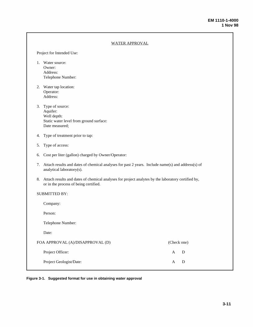
(3) If a suitable source exists onsite, that sourceshould be used. If no onsite water is available, the FDOshould both locate a potential source and submit the fol-lowing data in writing to the FA for approval prior to thearrival of any drilling equipment onsite. A suggestedformat is given in Figure 3-1.
(a) Owner/address/telephone number.
(b) Location of tap/address.
(c) Type of source (well, pond, river, etc.). If awell, specify static water level (depth), date measured,well depth, and aquifer description.
(d) Type of any treatment and filtration prior totap (e.g., none, chlorination, fluoridation, softening, etc.).
(e) Time of access (e.g., 24 hours per day, 7 daysper week, etc.).
(f) Cost per liter (gallon) charged byowner/operator.
(g) Results and dates of all available chemicalanalyses over past 2 years. Include the name(s) andaddresses of the analytical laboratory(s).
(h) Results and date(s) of chemical analysis forproject contaminants by a laboratory validated by USACEfor those contaminants.
(4) The FDO should have the responsibility toprocure, transport, and store the water required for projectneeds in a manner to avoid the chemical contamination ordegradation of the water once obtained. The FDO alsoshould be responsible for any heating, thermal insulation,or agitation of the water to maintain the water as a fluidfor its intended uses.
c. Grout.
(1) Cement. Cement grout, when used inmonitoring well construction or borehole/well decom-missioning, should be composed of Type I Portlandcement (ASTM C 150), bentonite (2-5% dry bentonite per42.6 kg (94 lb) sack of dry cement) and a maximum of 23to 26 L (6-7 gal) of approved noncontaminated-water persack of cement. The addition of bentonite to the cementadmixture will aid in reducing shrinkage and provideplasticity. Note that the maximum amount of dry bentonite
allowed here varies from the 10 percent allowable in ASTM D5092. The amount of water per sack of cement required for apumpable mix will vary with the amount of bentonite used.The amount of water used should be kept to a minimum.When a sulfate resistant grout is needed, Types II or V cementshould be used instead of Type I. Neither additives norborehole cuttings should be mixed with the grout. The use ofair-entrained cement should be avoided to negate potentialanalytical interference in groundwater samples by theentraining additives.
(2) Bentonite. Bentonite grout is a specially designedproduct, which is differentiated from a drilling fluid by its highsolids content, absence of cement and its pumpability. Atypical high solids bentonite grout will have a solids contentbetween 20 and 30 percent by weight of water and remainpumpable. By contrast, a typical low solids bentonite, as usedin a drilling fluid, contains a solids content between 3 and 6percent by weight of water. The advantages of using bentonitegrout include (Oliver 1997) :
C Bentonite grouts, when hydrated, exert constantpressure against the walls of the annulus, leaving noroom for contaminants to travel in the well.
C Bentonite grouts are more flexible and do not shrinkand crack when hydrated, creating a low permeabilityseal.
C Placement using bentonite grouts is much easierbecause more time is allowed for setting.
C Bentonite high solids grouts require less materialhandling than cement.
C Bentonite grouts are chemically inert, which protectspersonal safety, equipment, and water quality.
C Bentonite grouts have no heat of hydration makingthem compatible with polyvinyl chloride (PVC) casing.
C Wells constructed with bentonite grouts can be easilyreconstructed if necessary.
C Cleanup of bentonite grouts is much easier than withcement grouts.
Situations where bentonite grout should not be used are whenadditional structural strength is needed or when excessivechlorides or other contaminants such as alcohols or ketones arepresent. Under artesian conditions the bentonite does not havethe solids content found in a cement-bentonite grout and willnot settle where a strong uplift is present. Where structuralsupport is needed, bentonite grout does not set up and harden
EM 1110-1-40001 Nov 98
3-10
like a cement and will not supply the support a cement-bentonite grout will provide (Colangelo 1988).
(3) Equipment. All grout materials should becombined in an aboveground rigid container or mixer andmechanically (not manually) blended onsite to produce athick, lump-free mixture throughout the mixing vessel.The mixed grout should be recirculated through the groutpump prior to placement. Grout should be placed using agrout pump and pipe/tremie. The grout pipe should be ofrigid construction for vertical control of pipe placement.Drill rods, rigid polyvinyl chloride (PVC) or metal pipesare suggested stock for tremies. If hoses or flexible plas-tics must be used, they may have to be fitted with a lengthof steel pipe at the downhole end to keep the flexiblematerial from curling and embedding itself into the bore-hole wall. This is especially true in cold weather when thecoiled material resists straightening. Grout pipes shouldhave SIDE discharge holes, NOT end discharge. Theside discharge will help to maintain the integrity of theunderlying material (especially the bentonite seal).
d. Granular filter pack.
(1) Proper design of hydraulically efficientmonitoring wells can be accomplished by designing thewell in such a way that either the natural coarse-grainedformation materials or artificially introduced coarse-grained materials, in conjunction with appropriately sizedintake openings, retain the fine materials outside the wellwhile permitting water to enter. Thus, there are two typesof wells and well intake designs for wells installed inunconsolidated or poorly-consolidated geologic materials:natural developed wells and wells with an artificiallyintroduced filter pack. In both types of wells, the objectiveof a filter pack is to increase the effective diameter of thewell and to surround the well intake with an envelope ofrelatively coarse material of greater permeability than thenatural formation material (EPA/600/4-89/034). Thedecision to design the well using the natural formation asthe filter pack should include consideration that thenatural formation material may slough in high enoughabove the top of the well screen to leave insufficient roomfor the bentonite seal. All granular filters should beapproved by the FA prior to drilling and should bediscussed in the drilling plan. Discussions should includecomposition, source (natural formation or artificial),placement, and gradation. The FDO should eitherprescribe the gradation of the filter pack in the fieldsampling plan (FSP) or detail that it will be determinedafter a sieve analysis of the stratum in which the screen isto be set has been performed. If the actual gradation is tobe determined during drilling, more than one filter packgradation should be on hand so that well installation will
not be unnecessarily delayed. A 0.5 L (one-pint) repre-sentative sample for visual familiarization of each proposedgranular filter pack, accompanied by the data below, should besubmitted by the FDO to the FA for approval prior to drilling.Each sample should be described, in writing (see Figure 3-2for submittal format), in terms of:
(a) Lithology;
(b) Grain size distribution;
(c) Brand name, if any;
(d) Source, both manufacturing company and locationof pit or quarry of origin for artificial filter packs;
(e) Processing method for artificial filter packs, e.g., pitrun, screened and unwashed, screened and washed with waterfrom well/river/pond, etc.; and
(f) Slot size of intended screen.
(2) Granular filter packs should be visually clean (asseen through a 10-power hand lens), free of material thatwould pass through a No. 200 (75 µm [0.0029 in.]) sieve,inert, siliceous, composed of rounded grains, and ofappropriate size for the well screen and host environment.Organic matter, soft, friable, thin, or enlongated particles arenot permissible. A chemical analysis, including analytes ofproject concern, may be advisable in some circumstances.However, the reproducibility of that result should be evaluatedagainst the spatial and temporal variability of the aggregatesource and processing methods. The filter material should bepackaged in bags by the supplier and therein delivered to thesite.
e. Well screens, casings, and fittings.
(1) Typically, only PVC, polytetrafluoroethylene(PTFE), and/or stainless steel should be used. All PVCscreens, casings, and fittings should conform to NationalSanitation Foundation (NSF) Standard 14 for potable waterusage or ASTM Standard Specification F 480 and bear theappropriate rating logo. If the FDO uses a screen and/or casingmanufacturer or supplier who removes or does not apply thislogo, the FDO should
EM 1110-1-40001 Nov 98
3-11
WATER APPROVAL
Project for Intended Use:
1. Water source:Owner:Address:Telephone Number:
2. Water tap location:Operator:Address:
3. Type of source:Aquifer:Well depth:Static water level from ground surface:Date measured;
4. Type of treatment prior to tap:
5. Type of access:
6. Cost per liter (gallon) charged by Owner/Operator:
7. Attach results and dates of chemical analyses for past 2 years. Include name(s) and address(s) ofanalytical laboratory(s).
8. Attach results and dates of chemical analyses for project analytes by the laboratory certified by, or in the process of being certified.
SUBMITTED BY:
Company:
Person:
Telephone Number:
Date:
FOA APPROVAL (A)/DISAPPROVAL (D) (Check one)
Project Officer: A D
Project Geologist/Date: A D
Figure 3-1. Suggested format for use in obtaining water approval

EM 1110-1-40001 Nov 98
3-12
include in the drilling plan a written statement from themanufacturer/supplier (and endorsed by the FDO) that thescreens and/or casing have been appropriately rated by NSF orASTM. Specific materials should be specified in the drillingplan approved by the FA. All materials should be aschemically inert as technically practical with respect to the siteenvironment.
(2) All well screens should be commerciallyfabricated, slotted or continuously wound, and have an insidediameter (ID) equal to or greater than the ID of the well casing.An exception may be needed in the case of continuouslywound screens because their supporting rods may reduce thefull ID. If the monitoring well is to be subject to aquifer testing(slug test or pump test), a continuous wound screen should beused. Stainless steel screens may be used with PVC or PTFEwell casing. No fitting should restrict the ID of the joinedcasing and/or screen. All screens, casings, and fittings shouldbe new.
(3) Couplings within the casing and between thecasing and screen should be compatibly threaded. Thermal orsolvent welded couplings on plastic pipe should not be used.This caution also applies to threaded or slip-joint couplingsthermally welded to the casing by the manufacturer or in thefield. Several thermally welded joints have been known tobreak during well installation on a single project. Theavoidance should remain until the functional integrity ofthermal welds has been substantiated.
(4) Pop rivets, or screws should not be used onmonitor wells. Particular problems with their use includeanomalous analytical results, restriction of the well ID, and aloss of well integrity at the point of application.
f. Well caps and centralizers.
(1) The tops of all well casings should be telescopi-cally covered with a slip-joint-type cap. Each cap should becomposed of PVC, PTFE, or stainless steel. Each cap shouldbe constructed to preclude binding to the well casing due totightness of fit, unclean surface, or frost, and secure enough topreclude debris and insects from entering the well. Caps andrisers may be threaded. However, sufficient annular spaceshould be allowed between the well and protective casing toenable one to thaw any frosted shut caps. Caps should bevented, or loose enough to allow equilibration between hydro-static and atmospheric pressures. Special cap (and riser)designs should be provided by the FA or FDO for wells infloodplains and those instances where the top of the well maybe below grade, e.g., in roadways and parking lots.
(2) The use of well centralizers should be consideredfor wells deeper than 6 m (20 ft). When used, they should be
of PVC, PTFE, or stainless steel and attached to the casing atregular intervals by means of stainless steel fasteners orstrapping. Centralizers should not be attached to any portionof the well screen or bentonite seal. Centralizers should beoriented to allow for the unrestricted passage of the tremiepipe(s) used for filter pack and grout placement.
g. Well protection materials. Elements of well pro-tection are intended to protect the monitoring well fromphysical damage, to prevent erosion and/or ponding in theimmediate vicinity of the monitoring well, and to enhance thevalidity of the water samples.
(1) The potential for physical damage is lessened bythe installation of padlocked, protective iron/steel casing overthe monitoring well and iron/steel posts around the well. Thecasing and posts should be new. The protective casingdiameter or minimum dimension should be 100 mm (4 in.)greater than the nominal diameter of the monitor well, and thenominal length should be 1.5 m (5 ft). The protective postsshould be at least 80 mm (3 in.) in diameter and the topmodified to preclude the entry of water. If extra protection isnecessary, the protective posts can be filled with concrete.Nominal length of the posts should be 1.8 m (6 ft). Special cir-cumstances necessitating different materials should beaddressed in the drilling plan.
(2) Erosion and/or ponding in the immediate vicinityof the monitoring well may be prevented by assuring that theground surface slopes away from the monitoring well protec-tive casing and by the spreading of a 150 mm (6-in.) thick, 2.4m (8-ft) diameter blanket of 19- to -75-mm (3/4- to 3-in.)gravel around the monitoring well.
(3) The validity of the water samples is enhanced by alocking cover on the protective casing. The cover should behinged or telescoped but not threaded. Lubricants on protectivecovers should be avoided. Threaded covers tend to rust and/orfreeze shut. Lubricants applied to the threads to reduce thisclosure tend to adhere to sampling personnel and theirequipment. All locks on these covers should be opened by asingle key and, if possible, should match any locks previouslyinstalled at the site(s), and be made of noncorrosive matrial,such as brass.
h. Glues and solvents. The use of glues and solventsin monitoring well installation should be prohibited.
i. Tracers. Tracers or dyes should not be used orotherwise introduced into borings, wells, grout, backfill,groundwater, or surface water unless specifically approved inthe drilling plan. The drilling plan should describe any

EM 1110-1-40001 Nov 98
3-13
GRANULAR FILTER PACK APPROVAL
Project for Intended Use:
1. Filter Material Brand Name:
2. Lithology:
3. Grain Size Distribution:
4. Source:
Company that made product:
Location of pit/quarry of origin:
5. Processing Method:
6. Slot Size of Intended Screen:
Submitted by:
Company:
Person:
Telephone:
Date:
FOA APPROVAL (A)/DISAPPROVAL (D) (Check one)
Project Officer Name/Date: A D
Project Geologist Name/Date: A D
Figure 3-2. Suggested format for obtaining approval for filter pack
approved usage; chemical, radiological, and/or biologicalcomposition of the substances; and potential effects uponsubsequent chemical, radiological, or biological analyses ofthe injected media. Discussion should also be provided ofthe expected, post-injection visual appearance of the mediainto which the substances are to be introduced. Thediscussion should also include relevant Federal and stateregulations and those agencies' opinions relative to theapproved usage.
j. Lubricants. If lubrication is needed on thethreads or couplings of downhole drilling equipment, itshould be biodegradable and nontoxic. Vegetableoil/shortening or PTFE tape may be used. Additivescontaining lead or copper should not be used. The onlylubricant recommended for monitoring well joints is PTFEtape. The use and type of lubricants should be included inthe drilling plan and boring logs/well construction diagrams.
EM 1110-1-40001 Nov 98
3-14
k. Hydraulic fluids. Any hydraulic or other fluidsin the drilling rig, pumps, transmissions, or other field equip-ment/vehicles should NOT contain any polychlorinatedbiphenyls (PCBs).
l. Antifreeze. The use of any antifreeze (either acommercially available automotive variety or a localderivation) to prevent overnight water line freezing shouldrequire FA approval. If antifreeze is added to any pump,hose, etc., where contact with drilling fluid is possible, thisantifreeze should be completely purged with approved waterprior to the equipment's use in drilling, mud mixing, or anyother part of the overall drilling operation. A sample of theclean (approved) water that has been circulated through theequipment after antifreeze removal should be retained forlaboratory analysis. Only antifreeze without rust inhibitorsand/or sealants should be considered. Antifreeze usageshould be noted on the boring log, including the dates,reasons, quantities, composition, and brand names ofantifreeze used. Antifreeze usage should be a last resortoption. No antifreeze should be used in the drillingoperation. Overnight storage in a heated garage may be abetter option than spending time purging antifreeze andgetting frozen equipment ready to operate.
m. Agents and additives. The use of any materialsor substances other than those recommended herein for drill-ing, well installation, or development should be prohibited.Included in this suggested prohibition are lead shot, leadwool, burlap, dispersing agents (e.g., phosphates), acids,explosives, disinfectants, organic based drilling additives,metallic based lubricants, chlorinated and petroleum basedsolvents, adhesives, etc.
n. Summary. A materials usage summary, orMSDS should be provided of any drilling/well constructionmaterials which potentially could have a bearing onsubsequent interpretation of the analytical results. Anexample summary is provided at Figure 3-3.
3-9. Surface Runoff
Surface runoff, e.g., precipitation, wasted or spilled drillingfluid, and miscellaneous spills and leaks, should not enterany boring or well either during or after construction. Tohelp avoid such entry, the use of starter casing, recirculationtanks, berms around the borehole, surficial bentonite packs,etc., is recommended.
3-10. Drilling Through Contaminated Zones
a. Many borings and wells are drilled in areas that areclean relative to the deeper zones of interest. However,circumstances do arise that require drilling where the overly-ing soils or shallow aquifer may be contaminated relative tothe underlying environment. This situation may be
addressed by the placement of, at least, double casing: an outerpermanent (or temporary) casing sealed in place and cleared of allprevious drill fluids prior to proceeding into the deeper, “cleaner”environment. In this procedure, the outer drill casing is set andsealed within an “impermeable” layer or at a level below whichthe underlying environment is thought to be cleaner than theoverlying environment. The drilling fluids used to reach this pointare appropriately discarded, replaced by a new or fresh supply.This system can be repeated, resulting in telescopic drill casingthrough which the final well casing is placed. These situationsshould be addressed on a case-by-case basis in the drilling plan.
b. Caution should be exercised to prevent further migration ofcontaminants via boreholes, especially dense non-aqueous phaseliquid (DNAPL) migration. A recommended investigation strategyis to drill in expected DNAPL zones only after subsurfaceconditions have been characterized by drilling in surroundingDNAPL-free areas (the “outside-in” strategy). In DNAPL zones,drilling should generally be minimized and should be suspendedwhen a potential trapping layer is first encountered. Drillingthrough DNAPL zones into deeper strategraphic units should beavoided. Also non-invasive methods, such as geophysical orgeochemical surveys, can be useful at some sites to roughly definesubsurface geologic or contaminant conditions (USEPA OSWERDirective 9283.1-06).
3-11. Soil Sampling
a. Intact samples. Unless otherwise specified in thedrilling plan, intact soil samples for physical descriptions,retention, and physical analyses should be taken continuously andretained for the first 3 m (10 ft) and every 1.5 m (5 ft) or at eachchange of material, whichever occurs first, thereafter. Soil samplesshould be collected at intervals that are consistent with the goals ofthe project. These samples should be representative of their hostenvironment. Borehole cuttings do not usually provide thedesired information and, therefore, are not usually satisfactory.Sampling procedures should be detailed in the drilling plan.Additional guidance on soil sampling can be found in EM 200-1-3, EM 1110-1-1906 and ASTM Standard Guide D 6169.
b. Odors. At the detection of any anomalous odors (orvapor readings) from the boring or intact samples, drilling shouldcease for an evaluation of the odors and to determine the crew'ssafety. After the field safety representative completes thisevaluation and implements any appropriate safety precautions asmay be required in the site safety and health plan (SSHP), drillingmay only then resume. If the odors or vapor readings are judgedby the field personnel to be contaminant-related, intact soilsamples should be continuously taken until the odors/readings arewithin background ranges. These samples should be retained andpreserved in appropriate screw-capped sample jars for possiblechemical analysis. With the resumption of background readings,
EM 1110-1-40001 Nov 98
3-15
routine sampling should resume. Specific procedures shouldbe detailed in the FSP and SSHP.
c. Volume. Representative soil samples ofsufficient volume for physical testing from each sampledinterval should be retained for future reference orappropriate analysis. Upon boring completion, the numberof samples retained from that boring may be reduced,retaining at least representative samples of major units, keysamples, and those for testing requirements. Minimuminformation on each sample container should include theproject, depth below surface, and boring and samplenumber. All samples known or suspected to containcontaminants of concern should be so marked on both thesample container and boring log. No geotechnical datashould appear on the container that is not specified on theboring log. Containers should be kept from becomingfrozen. Soil samples known or suspected of beingcontaminated may have to be handled, stored, tested, and/ordisposed of as hazardous waste. Storage, packaging, andshiping instructions for soil samples for physical testingshould be prescribed in the drilling plan. USEPA haspublished additional guidance concerning the managementof investigation-derived wastes (IDW) for Superfundprojects (USEPA, EPA/540/G-91/009 and USEPA, OSWERPublication 9345.3-03FS) that should be incorporated intothe drilling plan, as appropriate.
d. Physical testing. Physical soil testing is afunction of the project. The drilling plan should detailspecific testing guidance and requirements. The appropriatenumber of field samples selected for physical soil testing aswell as sample retrieval locations should be determined bythe project geotechnical personnel. Procedures andequipment for soil testing are described in the currentEM 1110-2-1906 (or ASTM Standard Test Method D2487). Downhole geophysical logging may reduce the needfor sampling. Tested samples should be representative ofthe range and frequency of soil types encountered in theproject area and should specifically include the screenedinterval of each completed well. In addition, samples shouldbe obtained from borings that cover the geographic andgeologic range within the project area. The FDO shouldselect the particular samples. Samples selected for physicaltesting that are suspected to be contaminated should belabeled as such. Tests should include moisture content andthose tests necessary to determine the soil classification asdescribed in D 2487. Laboratory and summary sheetsshould be submitted to the FA after final test completion.The drilling and safety plans should address anycontaminant-related safety precautions for the physicalanalysis of these samples. The FDO is responsible forcommunicating these concerns to the laboratory performingthe soil testing. The testing laboratory is responsible fortaking all the necessary health and safety precautions
adequate to protect the laboratory personnel. Samples for physicalanalysis which are known or suspected to be contaminated shouldbe tested only in a soils laboratory equipped and managed to pro-cess contaminated samples.
e. Soil samples for chemical analysis.
(1) Samples should be extracted from an as intact,minimally disturbed condition as technically practical. Once at thesurface, the sampler should be opened, sample extracted, andbottled in as short a time as possible. Samples for volatile analysisshould be bottled, and capped within a VERY short time (about15 seconds from the time of opening the sampler). Each soilsample for volatile analysis should have minimal head space forrepresentative analytical results.
(2) All sampling equipment that will contact the sampleshould be thoroughly decontaminated between samples. This canbe accomplished by the use of a hot-water pressure washer or asfollows:
(a) Scrub equipment with a low-sudsing, nonphosphatedetergent in approved water.
(b) Rinse with approved water.
(c) When sampling for metals, rinse with 0.1 N nitric acid (4.2mL of concentrated nitric acid added to 1,000 mL (33 fl oz) ofwater). (CAUTION: Add acid to water, never add water toconcentrated acid.) Continue rinsing the sampling equipment nowwith distilled or deionized water. If the sampling equipment beingused is made of stainless steel, the use of 0.1 N hydrochloric acid(rather than 0.1 N nitric acid) is preferred to avoid oxidation(rusting) of the stainless steel. The 0.1 N hydrochloric acid is prepared by adding3.1 mL of concentrated hydrochloric acid to 1,000 mL (33 fl oz)of water. The same CAUTION applies: add the concentratedacid to the water, not the water to the acid.
(d) When sampling for organic volatiles, semivolatiles,or pesticides/PCBs, rinse with pesticide grade isopropanolfollowed by rinsing with distilled or deionized water. When usingisopropanol to decontaminate a sampler, the sampler must beallowed to completely air dry prior to reassembly.
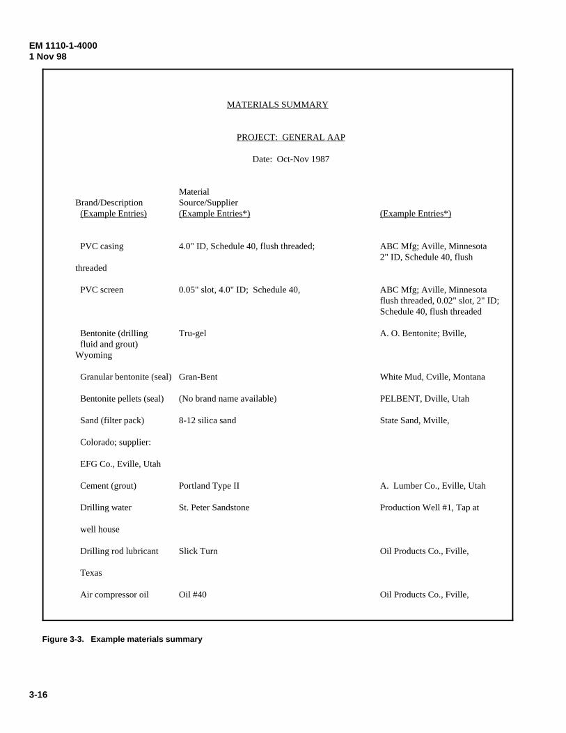
EM 1110-1-40001 Nov 98
3-16
MATERIALS SUMMARY
PROJECT: GENERAL AAP
Date: Oct-Nov 1987
Material Brand/Description Source/Supplier
(Example Entries) (Example Entries*) (Example Entries*)
PVC casing 4.0" ID, Schedule 40, flush threaded; ABC Mfg; Aville, Minnesota2" ID, Schedule 40, flush
threaded
PVC screen 0.05" slot, 4.0" ID; Schedule 40, ABC Mfg; Aville, Minnesotaflush threaded, 0.02" slot, 2" ID;Schedule 40, flush threaded
Bentonite (drilling Tru-gel A. O. Bentonite; Bville,fluid and grout)
Wyoming
Granular bentonite (seal) Gran-Bent White Mud, Cville, Montana
Bentonite pellets (seal) (No brand name available) PELBENT, Dville, Utah
Sand (filter pack) 8-12 silica sand State Sand, Mville,
Colorado; supplier:
EFG Co., Eville, Utah
Cement (grout) Portland Type II A. Lumber Co., Eville, Utah
Drilling water St. Peter Sandstone Production Well #1, Tap at
well house
Drilling rod lubricant Slick Turn Oil Products Co., Fville,
Texas
Air compressor oil Oil #40 Oil Products Co., Fville,
Figure 3-3. Example materials summary
EM 1110-1-40001 Nov 98
3-17
(3) Additional acquisition, preservation, and handlingcriteria for the chemical analysis of soils are found in EM200-1-3.
f. Liners. If sample liners are used, the followingshould apply:
(1) Use clear liners or take extra samples to ensurethat the sample is of sufficient quantity and quality for theintended analyses;
(2) Liner seams and ends should be “airtight,” i.e.,“moisture impermeable”;
(3) Borehole/drilling fluids should not be trappedwithin the liner;
(4) Liner or sealant interaction with the sampleshould not alter the sample's chemical composition; and
(5) Liners must be free of contamination and bedecontaminated prior to use. Decontamination may not benecessary if the liners have been packaged by themanufacturer and has intact packaging up to the time of use.
g. Location. All soil samples, except those forphysical and/or chemical analysis and reference shouldremain onsite, neatly stored at an FA-designated location.The disposition of these samples should be arranged by theFA. Samples from HTRW sites may have to be stored, andlater disposed of, off site. Depending on the site and itsaccessibility to the public, it may be permissible (dependingon state regulations) to stage the drums neatly on palletsimmediately adjacent to the boring/monitoring well location.If the option exists to dispose of IDW by spreading it on theground at the sampling location, it may not be cost-effectiveto stage the drums in a central location and then move themback to the boring/monitoring well location for disposal.Sample retention and disposal should be given detailedattention in the SAP. 3-12. Rock Coring
Bedrock should be cored unless the drilling plan specifiesotherwise. Coring, using a diamond- or carbide-studded bit(ASTM D 2113) , produces a generally intact sample of thebedrock lithology, structure, and physical condition. Theuse of a gear-bit, tricone, etc., to penetrate bedrock shouldonly be considered for the confirmation of the “top of rock”(where penetration is limited to a few meters [feet]), theenlargement of a previously cored hole, or the drilling ofhighly fractured intervals. Except as noted below, guidancefor preserving, storing, photographing, marking, cataloging,
and handling of rock core samples may be found in ASTM D 5079.
a. The coring of bedrock or any firm stratigraphicunit should be conducted in a manner to obtain maximum intactrecovery. The physical character of the bedrock (i.e., fractures,poor cementation, weathering, or solution cavities) may lessenrecovery, even with the best of drillers and equipment.
b. The minimum core size should be an “N” series, 50mm (2 [plus]-in.) diameter. Larger bit (hence, core) diametersmay be needed to enhance core recovery.
c. While drilling in bedrock, and especially whilecoring, drilling fluid pressures should be adjusted to minimizedrilling fluid losses and hydraulic fracturing. All pumpingpressures should be recorded.
d. Rock cores should be stored in covered core boxesto preserve their relative position by depth. Intervals of lost coreshould be noted in the core sequence. Boxes should be markedon the cover (both inside and outside) and on the ends to provideproject name, boring number, cored interval, and box number incases of multiple boxes. Any core box known or suspected tocontain contaminated core should be appropriately marked on thelog and on the box cover (inside and out), and on both ends. Theweight of each fully loaded box should not exceed 34 kg (75 lb).No geotechnical or contaminant data should appear on or withinthe box that is not specified on the boring log. As a minimum,the estimated number of boxes required for a given boringshould be on hand prior to coring that site.
e. The core within each completed box should bephotographed after the core surface has been cleaned or peeled,as appropriate, and wetted. Each photo should be in sharp focusand contain a legible scale in centimeters (feet and tenths of feet).The core should be oriented so that the top of the core is at thetop of the photo. Each photo should be annotated on the backwith the project name, bore/well designation, box number, coreddepths pictured, and date photographed. One set of glossy colorprints should be sent to the FA after the last coring. In addition,all negatives should be delivered to the FA after the FA hasreceived the prints. (See ER 1110-1-1803 for additional guid-ance on core management.)
f. All rock core, except that for analysis and refer-ence, should be neatly stored at an FA-designated location. Thedisposition of these samples should be arranged by the FDO.Specific instructions for the storage or required packaging andmethod of shipment to the laboratory should be provided in thedrilling plan.
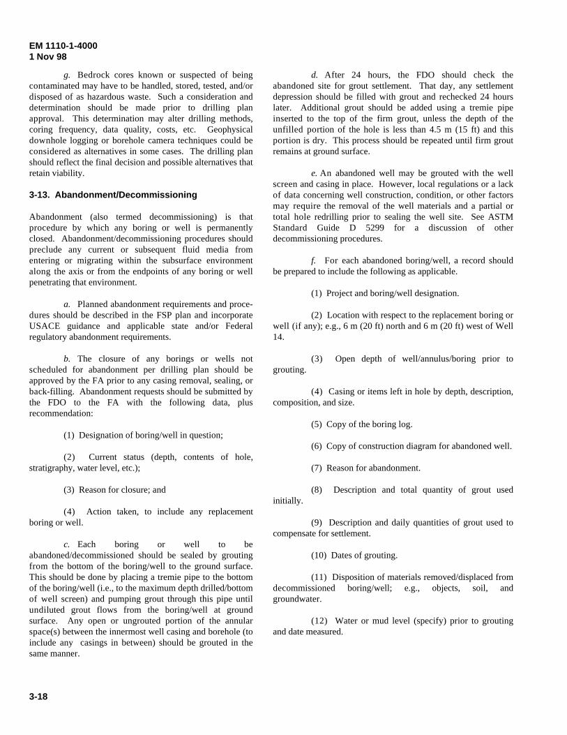
EM 1110-1-40001 Nov 98
3-18
g. Bedrock cores known or suspected of beingcontaminated may have to be handled, stored, tested, and/ordisposed of as hazardous waste. Such a consideration anddetermination should be made prior to drilling planapproval. This determination may alter drilling methods,coring frequency, data quality, costs, etc. Geophysicaldownhole logging or borehole camera techniques could beconsidered as alternatives in some cases. The drilling planshould reflect the final decision and possible alternatives thatretain viability.
3-13. Abandonment/Decommissioning
Abandonment (also termed decommissioning) is thatprocedure by which any boring or well is permanentlyclosed. Abandonment/decommissioning procedures shouldpreclude any current or subsequent fluid media fromentering or migrating within the subsurface environmentalong the axis or from the endpoints of any boring or wellpenetrating that environment.
a. Planned abandonment requirements and proce-dures should be described in the FSP plan and incorporateUSACE guidance and applicable state and/or Federalregulatory abandonment requirements.
b. The closure of any borings or wells notscheduled for abandonment per drilling plan should beapproved by the FA prior to any casing removal, sealing, orback-filling. Abandonment requests should be submitted bythe FDO to the FA with the following data, plusrecommendation:
(1) Designation of boring/well in question;
(2) Current status (depth, contents of hole,stratigraphy, water level, etc.);
(3) Reason for closure; and
(4) Action taken, to include any replacementboring or well.
c. Each boring or well to beabandoned/decommissioned should be sealed by groutingfrom the bottom of the boring/well to the ground surface.This should be done by placing a tremie pipe to the bottomof the boring/well (i.e., to the maximum depth drilled/bottomof well screen) and pumping grout through this pipe untilundiluted grout flows from the boring/well at groundsurface. Any open or ungrouted portion of the annularspace(s) between the innermost well casing and borehole (toinclude any casings in between) should be grouted in thesame manner.
d. After 24 hours, the FDO should check theabandoned site for grout settlement. That day, any settlementdepression should be filled with grout and rechecked 24 hourslater. Additional grout should be added using a tremie pipeinserted to the top of the firm grout, unless the depth of theunfilled portion of the hole is less than 4.5 m (15 ft) and thisportion is dry. This process should be repeated until firm groutremains at ground surface.
e. An abandoned well may be grouted with the wellscreen and casing in place. However, local regulations or a lackof data concerning well construction, condition, or other factorsmay require the removal of the well materials and a partial ortotal hole redrilling prior to sealing the well site. See ASTMStandard Guide D 5299 for a discussion of otherdecommissioning procedures.
f. For each abandoned boring/well, a record shouldbe prepared to include the following as applicable.
(1) Project and boring/well designation.
(2) Location with respect to the replacement boring orwell (if any); e.g., 6 m (20 ft) north and 6 m (20 ft) west of Well14.
(3) Open depth of well/annulus/boring prior togrouting.
(4) Casing or items left in hole by depth, description,composition, and size.
(5) Copy of the boring log.
(6) Copy of construction diagram for abandoned well.
(7) Reason for abandonment.
(8) Description and total quantity of grout usedinitially.
(9) Description and daily quantities of grout used tocompensate for settlement.
(10) Dates of grouting.
(11) Disposition of materials removed/displaced fromdecommissioned boring/well; e.g., objects, soil, andgroundwater.
(12) Water or mud level (specify) prior to groutingand date measured.
EM 1110-1-40001 Nov 98
3-19
(13) Remaining casing above ground surface:type (well, drill, protective), height above ground, size, andcomposition of each.
(14) Report all depths/heights from ground sur-face.
(15) The original record should be submitted tothe FA.
g. Replacement well/borings (if any) should beoffset at least 6 m (20 ft) from any abandoned site in a pre-sumed up- or cross-gradient groundwater direction.
3-14. Work Area Restoration and Disposal ofDrilling and Cleaning Residue
All work areas around the wells and/or borings should berestored to a condition essentially equivalent to that ofpreinstallation. This includes the disposal of boreholecuttings and rut removal. Borehole cuttings, discarded sam-ples, drilling fluids, equipment cleaning residue, and waterremoved from a well during installation, development, andaquifer testing should be disposed of in a manner approved
by the FA, host installation, and consistent with applicable stateand federal regulations. These types of materials are consideredinvestigation-derived wastes (IDW). (See USEPA EPA/540/G-91/009 for USEPA guidance on the management of thesematerials.) Whatever procedures are followed, the leaving ofbarrels containing drill cuttings, excess samples, and water atvarious unsecured locations around the site at the completion ofwell installation is not appropriate. All drums/barrels filled onsiteshould be permanently labeled (in a waterproof manner andresistant to fading) and inventoried as to their contents and source.Restoration and disposal procedures (to include disposal loca-tion(s)) should be discussed in the FSP. Depending on the site andits accessibility to the public, it may be permissible (depending onstate regulations) to stage the drums neatly on pallets immediatelyadjacent to the boring/monitoring well location. If the option existsto dispose of IDW by spreading it on the ground at the samplinglocation, it may not be cost-effective to stage the drums in a centrallocation and then move them back to the boring/monitoring welllocation for disposal.
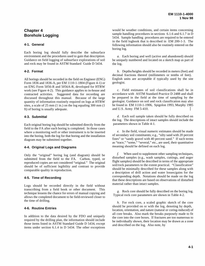
EM 1110-1-40001 Nov 98
4-1
Chapter 4Borehole Logging
4-1. General
Each boring log should fully describe the subsurfaceenvironment and the procedures used to gain that description.Guidance on field logging of subsurface explorations of soiland rock may be found in ASTM Standard Guide D 5434.
4-2. Format
All borings should be recorded in the field on Engineer (ENG)Form 1836 and 1836-A, per EM 1110-1-1804 (Figure 4-1) oron ENG Form 5056-R and 5056A-R, developed for HTRWwork (see Figure 4-2). This guidance applies to in-house andcontracted activities. Suggested data for recording arediscussed throughout this manual. Because of the largequantity of information routinely required on logs at HTRWsites, a scale of 25 mm (1 in.) on the log equaling 300 mm (1ft) of boring is usually adequate.
4-3. Submittal
Each original boring log should be submitted directly from thefield to the FA after each boring is completed. In those caseswhere a monitoring well or other instrument is to be insertedinto the boring, both the log for that boring and the installationdiagram may be submitted together.
4-4. Original Logs and Diagrams
Only the “original” boring log (and diagram) should besubmitted from the field to the FA. Carbon, typed, orreproduced copies are not considered “original.” The originalshould be of sufficient legibility and contrast to providecomparable quality in reproduction.
4-5. Time of Recording
Logs should be recorded directly in the field withouttranscribing from a field book or other document. Thistechnique lessens the chance for errors of manual copying andallows the completed document to be field-reviewed closer tothe time of drilling.
4-6. Routine Entries
In addition to the data desired by the FDO and uniquelyrequired by the drilling plan, the information should includethose items listed in ASTM Standard Guide D 5434, exceptitems under section 6.1.4 in D 5434. The other exceptions
would be weather conditions, and certain items concerningsample handling procedures in sections 6.1.6 and 6.1.7 in D5434. Sample handling procedures are required to be enteredin the field logbook that is described in EM 200-1-3. Thefollowing information should also be routinely entered on theboring log.
a. Each boring and well (active and abandoned) shouldbe uniquely numbered and located on a sketch map as part ofthe log.
b. Depths/heights should be recorded in meters (feet) anddecimal fractions thereof (millimeters or tenths of feet). English units are acceptable if typically used by the sitegeologist.
c. Field estimates of soil classifications shall be inaccordance with ASTM Standard Practice D 2488 and shallbe prepared in the field at the time of sampling by thegeologist. Guidance on soil and rock classification may alsobe found in EM 1110-1-1906, Spigolon 1993, Murphy 1985and U.S. Army FM 5-410.
d. Each soil sample taken should be fully described onthe log. The descriptions of intact samples should include the parameters shown in Table 4-1.
e. In the field, visual numeric estimates should be madeof secondary soil constituents; e.g., “silty sand with 20 percentfines” or “sandy gravel with 40 percent sand.” If such termsas “trace,” “some,” “several,” etc., are used, their quantitativemeaning should be defined on each log.
f. When used to supplement other sampling techniques,disturbed samples (e.g., wash samples, cuttings, and augerflight samples) should be described in terms of the appropriatesoil/rock parameters to the extent practical. “Classification”should be minimally described for these samples along witha description of drill action and water losses/gains for thecorresponding depth. Notations should be made on the logthat these descriptions are based on observations of disturbedmaterial rather than intact samples.
g. Rock core should be fully described on the boring log. Typical rock core parameters are shown in Table 4-2.
h. For rock core, a scaled graphic sketch of the coreshould be provided on or with the log, denoting by depth, location, orientation, and nature (natural or coring-induced) ofall core breaks. Also mark the breaks purposely made to fitthe core into the core boxes. If fractures are too numerous tobe individually shown, their location may be drawn as a zoneand described on the log. Also note, by
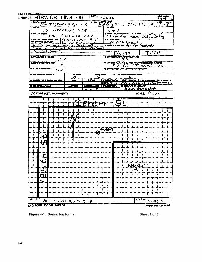
EM 1110-1-40001 Nov 98
4-2
Figure 4-1. Boring log format (Sheet 1 of 3)
HTRW DRILLING LOG ~-'IIJI,IIlll
f.1uJ9S·O/
UIZIUNO 'fVti'U 01' OftUI'IO I c. N IE"- ., '5' u _c;L V'l (1, "t I I "4 II NtO....,.._INil~ I hnllo!.V Sf-.!1"'1'"1 ~..u.A"'-V'3
3'' o. D. S+n.inless: S.~tl "C'll ·~r- '!.l)OOI"\-S ( Ch/O_I"Y\ i r <1. I 1"1 ond _, bu. II e_ ht- v, UlA:mf.
1 z. o'
/2.0 1
WITMS Gn411'1~ OIWP!II"'CIII'II I ~~ 121.1Dt.M.CCII'II e.-rlii '1.. <t tiio~ ,-~PI-t l. .,. a 111:.1 L.CN:i '!. ~ t. oa.IIIICI::llo8IY IS ..
LOCATION SKETCK'COMMENTS scALE: Ill::. zo'
... ) ..... ~.--! .... J ..... J ..... ~ .... ~ ..... ~ ..... ~ .. b.:n· -1tt~~_...~--...l---~ .. ll.) ..... l ..... ~ .. ) ..... r ... ~.i ..... J ..... ~ .. ) ..... : : : : i : : : rCL~ ~ : :~. : : \::cJ L : : ! : : : : : :
:~::t::: ·-·+·· ........ ; ....... ..... j····
::~::j~::: ·--··j····
"'""i'"' ..... r·· .... + ... ..... j-..
-·t.... . . . . . . . . - ..... :--··· ..... -f ......... -~---4·. ···'· -··i-·· .. .;.. ·--t-... ;. ..... a ...... ~-· .. ···>···· -i ...... i· .... ..c •••••• ;.. ............. t ........ ~ ....... _~ .......... ~ .................. ..-~ ......... ~ ........ ;. ...... -
::{::: :=~~::~::i::i::&.f:t::1:::i:=~:::f::::J~:::j.::::t::::t:.::l::=:t=::t::::t::=t:~::!::::+::::t::::1:::= --···:t. ••·· ··--!----·:----:--· .. t·~····~·····t· .. ··~· .. ··!··· .. ~-·~;t·iO~· .. ··: .. ··: .. ···;-.. ··:· .. ··:·····:·····r--··: .. ···:······:--···:··· ..
• I 0 0 • " I ••• ..,~,~ f f • I I ~ 0 o o • •
·-·¥···· ··-1··-·i·····t .. · .. t·-· -·--i'··-t·· .. ·r··· .. i··~··-r .... ·r·····j·····t··--t·----t··--·!·····i .. ···-r·····t·····J··--·t····-r·····r····· ·-~ ··-!··-·t····t·····r···· - .. t····t·· .. ·r·····!··--·1--···t·····i·····j--···t····t·····f···--j·--··~·····-t-·····r·····j·····t····t .. ···t····· lin : : : : . : : : : : : : , : : = : : : : : : : :
.. ~_·J · ··-r·-·r····r·----r·····l--··-r····r····-r·--··;·· .. ·r····r··-r·· : : : : : : : : : : : : ' . : . . . . ' . . . .......... ""......... ····!··-~~t··· .. t·· .. -f·····~····-:-····?···· ·~·····;· · ···:··· ·· ·:·····:···· · · ·r··-1····1~~--~ ~~--· -1-.... ~ .. ! · .. ···r ·- ·· · i .... · · .. r~ ~ ... ~·r .... · ··r· · .....
: : : : ~ : : : ! : : : • ; : ; : : : : : : : : •••• ..;....... • .... ; ........ ~ ........ ~ ........ ~ .............. ~ ....... ). ...................... ~~--·· .. ~ ......... ~ ..... ~ ···~:_~·····~:.· ~----,..:;··-·-!:_ ....... ~:_ ...... ~ .. -:-:_ .......... ~:.· ·····::'"····t:_ ........ ~:. ·····!.:·····
:.....- ! ~ ~ j ~ ~ ~ ~ ~ ~ l .
:~ :::1 :::rF:::::::r:::r:=t:::r::j:::::r::r:::::::: · · · · · · · · · · · .... ft -····~.:··· .. 1.·--··r.-.... j_ ... • .. ;···--r ...... :_~--- .. ;.~--· .. ;_ ...... 1 ...... ~ .. -· .. ·.··-· ::.f::~::·:::~~J;:::::::-·.:-:::r:::.r·:.:t:::~ L.;.IJ : : : ; : : : : : : : . ..... ;..... .. ... ··~ · ....... ~ ........ ·r· · · ··r · ....... ~-·· ··r· ..... ·r· ..... ·r·· · · · ;-· · · · t··A·- t· · · ·· ~ · ....... .. · · ,: .. · · ...... :,. ..... · ·•· · · .... : · · ··· ~···· · .:,. .. · · ..... ~ · ........ , ........ ~· · · .... ~;- ··- ·. ; .. ~ · .... r.:\J : : : : . : : : : ; : ' i : : : : : : : :
::~:-. _· :::::;:::::r:::r :r::::: :r::r:::r:::::: ::c:r::::,:::: : = ::L t·::,·:::::r··:r ··::··· ·;::::t t . .......... .. ... i·····]· .. ···r .. ···[·····~--.. ·i· .. -+ .... ! .. ···~···-·:··--··:·· .. ·;---· .......... t ..... : ........... ; ..... L .. L ... l ..... ; ...... ~ .. -+ .. ..
..... !.... . .... ;- .... ! ..... ·: .. ·--r .... , .. -.. ; ...... :. -.... , ..... 1··- .. t·· .. ;··· ... ~. ... .. ........ t .. .. : ..... ~ ..... ~ .... .. r ... T .... : .... -~--- ... : ....
5t~ 1 HoLe NO. M ~ q ~-ot ENG FORM 5056-R. AUG 94 !Proponent: CECW-EGI
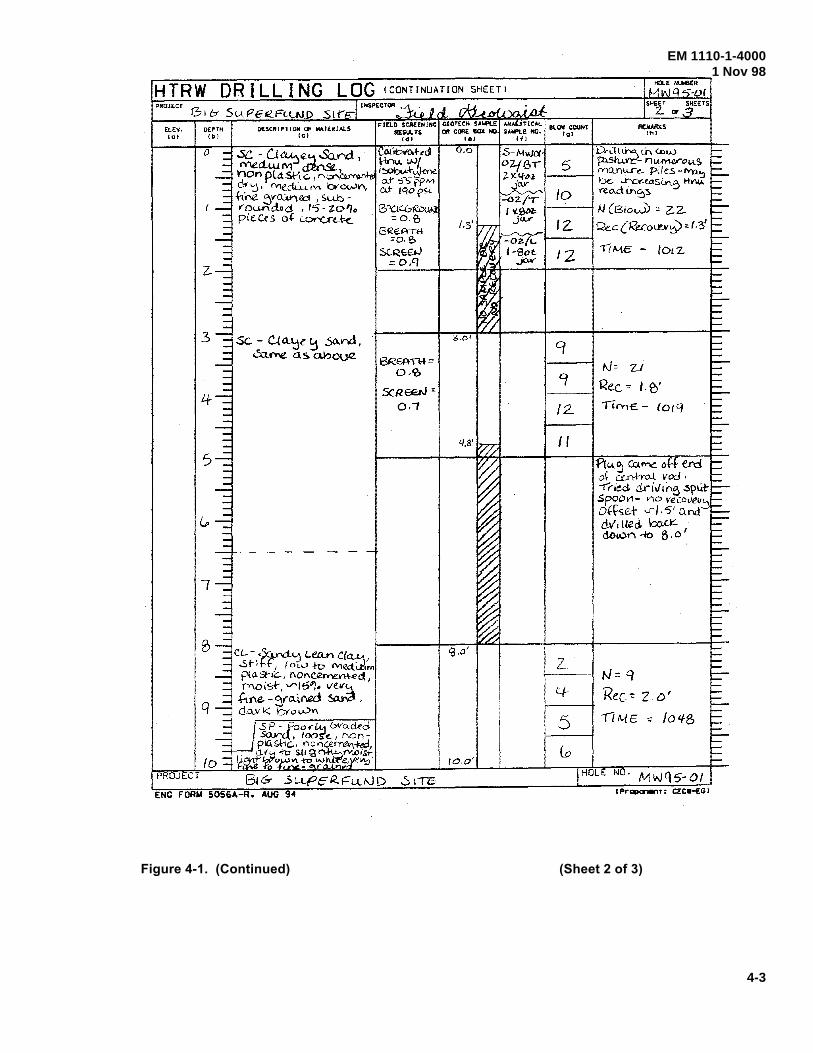
EM 1110-1-40001 Nov 98
4-3
Figure 4-1. (Continued) (Sheet 2 of 3)
HTRW DRILLING PRWECf
ELEY. IOI
DEPTH II>!
0 (){ibYM-ed l-in"'" w[ i~f-~1-ene aJ" ':fi5 f{>M Cd" ICIO('~i.
BPc.l~&Rou - -::o_e, SR€A-ni
=o. e. SCRE£t-1 = o.CJ
CL-~ Lea..n ct .Sti , I ow to M~:m pta.St-1<::..., r\01"\ClZ.....-.em-E"d
mois-t-, v--j~l). ~ ' Me. - ~ro..i.r-.ed , d.o..v K bY o v.)n
PROJEC:T 5u..pt:R..Fu.".JD -5 I"TE ENG FORM 5056A-R. AUG 9~
/.3'
9.o'
10.0'
REIIARKS ,..,,
J:k.:t It""' tn <ow 5 p:tstW"C'- nu.N\Vo"'-~
1----1 rY)QY"ltU""'L. pik.s-~ OC Lr'CV'-taSi..n5 11'!"'\IA. vec:xd Lnf:)S to
'----! 1-J (Blow) -:: 22.
12. R.e.c(Reco\£1r~:: f.?/ 1-----+
'2 1ffv\E - lOlZ..
I\]= Z..1
~-------Cf---1 Rec = ,_ ~~ /2.
I I
z_
4-
5 G
fliYI€.- (O(Cf
11"'-5 ilif\""\C o.f erd ~ Ci.n-ho.l v-od. -rhed driv'tn6 ~plrt.srooV1- no vecovevc. Offset ...rl .5' Cu"'d-> dv'~ lied. kn<-k Go!Vr"\ ...fo 8, 0 I
t-J=q
'Rec-= z.o' -r7t4.E -= /olfB
HOLE No. Mwqs-ot CPr~t: CEC•-EGJ
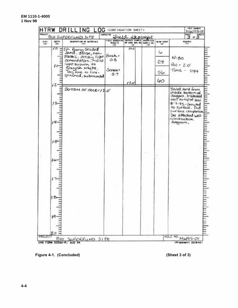
EM 1110-1-40001 Nov 98
4-4
Figure 4-1. (Concluded) (Sheet 3 of 3)
HTR W DRILLING LOG ICONfi NU•TIOH SH(( fl 1 .~·.~, .....,c, Jr~ ~
6<6 SuPeRO::u.ND :>1 Tl: ·' L.r. M o -3' .. 3'~ ..... ... ... OUOI.I#'fi.Ol G" • tt..ttiiiU ti.U IOIIWII. CllalUioo Ulft.( lUi.
a.o.~1 ........ . "' ••• ••• ....... -=-~- """"'"" .. ~ ... • •• . .. ... 1• 1 Ul
/0 ~ 5 p.. t''~ 6>-o..Ud l l>-0 ~ _: ~ , dYls.t.1 f\on- r... = -:: PIAso.·c. , ~Hct..!:l I~ &eo..~>- • fl.l~ao :::-: C~""">f~.,.IO"- , M.Oo ~~. o.?; Z_<f =
11-7. ' •!:)~'<~- bvov.>"- -t-o ia<c . z.o' ~ ~ ~Y"-!)1~ Wl\.i. +"" ' & t t.cl'l< -rlM E:. - ll'f't != : ""'::) ~ -~o r~-
0 · "1 5(o ~
~ \?. y "-VVed ' s....b•"'-WJ<d t::-= /2.d iQo ~ z. - 1-
= Bo-m>Nt o!" Hoc.£: /2 .o' ~1«1 Jard .r ... ~ ... ~ -= th$o((~ tl:>llom I)( F-: ~ .. . ' ""11411&{ ~ I~
W<.l IoofT>{> of S<4J ~ I - 8·1-'15 -~ ...... .~ ~
~ .fl>S'W"40.ct: . O.d ~ ...: :.••de. c.. """jlU +;.,.. =-~ ::.u c:ttW.«f well ~ .. CDn.Sh..ci\Oo\. = Jl.f...: <!.l>e."•"'. :::-~ : = ~ :::.. - = I~ ~ I : F"" ~ ~ -:: F-~ E
'"'...: f:::. = r=-
__::: ~ -:: F-:: ~ , ,...: = :: ~
:: = =-~ ~ .. '~ = I "' :::-: =
--= =-: ~ ;; r= 1'1-7. t::-= r= ~ b -:: ::: -'1...:> = = e KUJt< Bre:. <:u.veR~~ .vo 5 t re IHOl~ Nu.M,.JtlS -01
t."'"" ,. '-"" :~O,.U,--ft • AIJG , .. I~GOOI"'""' CICw.IGI
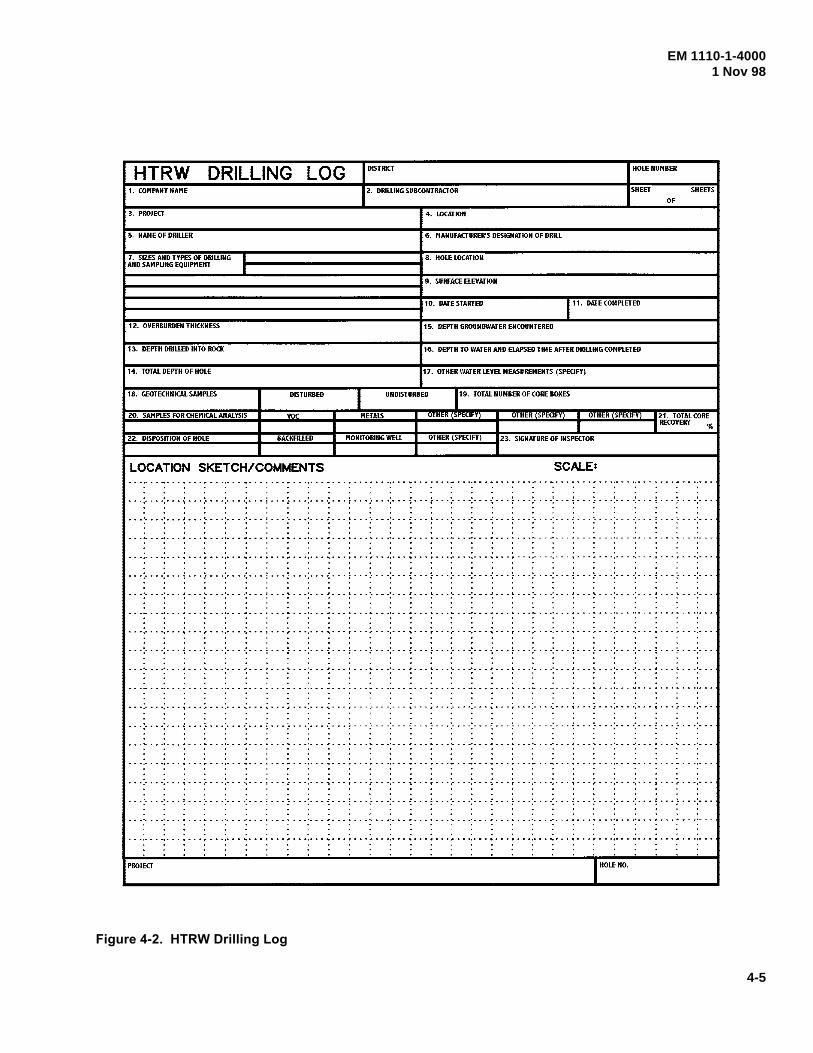
EM 1110-1-40001 Nov 98
4-5
Figure 4-2. HTRW Drilling Log
HTRW DRILLING LOG DISTRICT HOLE NUMBER
1. COMPANY NAME Z. DRILLING SUBCONTRACTOR SHEET SHEETS
OF
3. PROJECT 4. LOCATION
5. NAME OF DRILLER 6. MANUFACTURER'S DESIGNATION OF DRIU
7. SIZES AND TYPES OF DRILLING ··---------------..... 8. HOLE LOCATION AND SAMPLING EQUIPMENT I
lo----------------------------19. SURFACE ELEVATION
1-----------------------------110. DATESTA~ED 111. DATE COMPLETED
1 Z. OVERBURDEN THICKNESS 15. DEPTH GROUNDWATER ENCOUNTERED
13. DEPTH DRILLED INTO ROCK 16. DEPTH TO WATER AIID ELAPSED TIME AFTER DRIWIIG COMPLETED
14. TOTAL DEPTH OF HOLE 17. OTHER WATER LEVEL MEASUREMENTS (SPECIFY)
18. GEOTECHNICAL SAMPLES DISTURBED
1
UNDISTURBED rg· TOTAL NUMBER OF CORE BOXES
ZO. SAMPLES FOR CHEMICAL ANALYSIS YOC METALS OTHER (SPECIFY) OTHER (SPECIFY) I OTHER (SPECIFY) I Z1. TOTAL CORE
I I RECOVERY %
.. Z:;;:Z:;;,·..:D;:;IS::,POS=IT.:.:IO:;;;N::.;;O:,.F ;:,HO:;:LE;:;.. ____ .. ....;B;;;A;;;CK;;;F,;;IL;:;LE;;:D;...~t-.:.:M;,;O,;;,NI;,;,TO:;:RI;;;N;;;G;;.W;:,E;;:L;;,L_ .. ..;o;,;,T,;;H;;ER,;.(:,;S,;.PEC=IFY.;.:.J --123. SIGNATURE OF INSPECTOR
LOCATION SKETCH/COMMENTS SCALE:
0 • I I • I I 0 I I I I t 0 I I I I I I I t I I I I I I ~ ..• · .. · ................ · .. -..... ~ ......... ' .... · •... : ...• - . - -.- .. · •. - - : . - - .- - . -.- - - ~ - - - ; - - -.- . - -.- . - i - ........ - - - -•.. - •... ; . - -.- ..
. . . . . . . . . . . . . . . . . . . . . -.- -- ··- ..•. --I'- -.... - ... -... -.. ,. ... , ...... - .• - ..... - ....... - ..•.......... - - .. -..... - --- . - .. -. -". --,. ... , .. - ...... , . -. ~ ... ,. --
... :- - - -:- . - ~ . - . :- - - . :- .. -:. - . ~ .. - :- ... :. - - -: . - . ; ... :- . - -:- - . ~ - .. : - .. :- .. -:- - . -: ... : .. -:- . - -: ... ; - .. ;. . - -:- - - -:. - . i - . - :- - - -:- - -
••• '• •• •' ••• t ••• '. ••• '• ••• • ••• ~ ••• '\. ••• • •••• • •• , I ••• '• • - •'• •• I ••• I. ••• '• ••• • ••• .I ••• \ ••• '• ••• • ••• J ••• 1. ••• '· • - .• ••• ,I • • • \. ••• • ••• . . . . . . . . . . . ' . . . . . . . . . . . ' . . . .
. . . . . . ' . ' . . . . . - . . . . . . . . . . . . . • • • , •••••••• ' ••• ' ••••••• -. ••• , ••• ,. ••• , ••• -. ••• ' - - - r - •• , ••• "'\ ••• f' ••• , •••• , ••• '\ ••• t ••• , •••• , ••• ' ••• , ••••••• -. ••• ' ••• ,. ••• , •••
•, •'• • • •'• • , I • • , '1. • • •'• o • ~ ••• Ito • o '\. ••• • •• • .I o o , I o • o ... • • •'• • o -1 • o • I. • o • '• • • •'• • o I • • • \ • • •'• • • •' o • • I o o • \. • • •'• • • ~ • • • .I • • • I. • • ·'· • • . . . . . . . . . . . . . . . . . . . . . . . . . . . .
. . . . . . . . . . . ' . . . . . . . . . . . . . . . . • • •,• • • •,• • • \ • • • /' • • •,• • • ". • • • 1 • • • I • • •,• • •-. • • • r • • • ,· "• ·,· • • '\" " "." • • ,· • " "•""' • '\ • • "t "" "•" " ""•""" '\" "" T " " •,• "" "•" " " 1 " " "T " " "•"" "
.. -:-.--:- .. ~- --:---:--.-:--- ~-. -:-.--:-.--:- .. :.--:----:--- -:---=- --:-.--:--. ~-- -; ---:-. -->·. ~-- -:-- <- ---:---:---:- .. -:---, • •"- • • .•. • 0 if. • • ~ • , •'• a , ~. • • o1< • • , 'I. , • •'• • • .1', • , I • • , '- • • •'• •,. ~ • • • t. • , •"• , • •'• • • .I • • •" • • •'• • • .•., • if. • • t,. • o •'• • • •' o • • I • • • t,. • • •'• • • . .. . . . . . . . . . . . .
-.-:-.--:- .. ;. --~-. -:----:--- ~ .. -:- .. -> ---:- .. ; .. -:----:--- ~-- .;. --:- .. -:--. ~-. -~ .... : .... : ... ;. --~-- -:----:.-.; ---:-.--:---
-· ·:· ·--:--. ~- --:--.-:--. ·:- -- ~ .. -:-.--:----:- .. ; .. -:--- <- -- -:-· -:. ··:· .. ->-. :-. ·: .. -:-. --:· .. ~- --;-- -:----:- .. ~. --:- *. -:---
PROJECT I HOLEIIO.
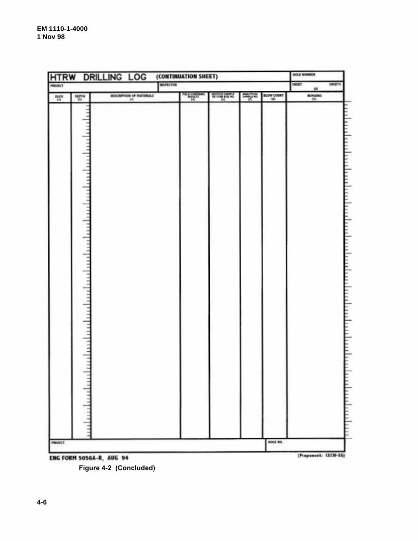
EM 1110-1-40001 Nov 98
4-6
Figure 4-2 (Concluded)
HTRW DRILUNG LOG ((OIITIIIIATIOII SHEET) --_, 1- _, s-:n • =v r.:M~ ... T _...... .... ..u - -- -.. .... -w- • ..
-= =-- : -: F-: ~ ...: ~
: ~ -: :...
~ ....; f:-.
: f E ....; :-: :
-: :-....;
: :;..
: : - ::-~
- 1:-F
....; ~ r:-: ~ - F-: F
-= 1:---= F : ::: ....:;
I='" : ~ ...: 1:--: F : : ....:; :-: : ...: ::-: ..: ~ : 1=-
: ~ -:
I:_ :
;:-
- 1 ..... EIIG FOitM SOSIA· I , AUG H

EM 1110-1-40001 Nov 98
4-7
Table 4-1SOIL PARAMETERS FOR LOGGING
PARAMETER EXAMPLE
Classification Sandy clay
Depositional environment and formation, if known Glacial till, Twin Cities Formation
ASTM D 2488 Group Symbol CL (field estimate)
Secondary components and estimated percentages Sand: 25 percent Fine sand 5 percent Coarse sand 20 percent
Color (Soil color charts such as Munsell Soil or the GeologicalSociety of America (GSA) Rock Color Chart are helpful fordescribing the color of soil samples. If a color chart is used, giveboth narrative and numerical description and note which chartwas used. Suggested standard colors can be found in Spigolon1993)
Gray: (Gr) (7.5 YR 5.0 (Munsell))
Plasticity Low plasticity
Consistency (cohesive soil) Very soft, soft, medium stiff, very stiff, hard
Density (noncohesive soil) Loose, medium loose, dense, very dense
Moisture content Use a relative term. Avoid a percentage unless a value has been measured.
Dry, moist, wet, saturated
Structure and orientation No apparent bedding: numerous vertical, iron-stained, tight fractures
Grain angularity Rounded
depth, the intervals of all lost core and hydrologicallysignificant details. This sketch should be prepared at the timeof core logging, concurrent with drilling.
i. A record of the brand name and amount of any bentoniteused for each boring should be made on the log, along withthe reason for and start (by depth) of this use. If measured,record mud viscosities and weight.
j. The drilling equipment used should be generallydescribed on each log. Include such information as rod size,bit type, pump type, rig manufacturer, and model.
k. Each log should record the drilling sequence; e.g.:
(1) Opened hole with 8-in. auger to 9 ft;
(2) Set 8-in. casing to 10 ft;
(3) Cleaned out and advanced hole with 8-in. roller bit to 15 ft (clean water, no water loss);
(4) Drove 1-3/8-in. ID X 2-in. outside diameter (OD)sampler to 16.5 ft;
(5) Advanced with 8-in. roller bit to 30 ft, 15-gal water
loss;
(6) Drove 1-3/8-in. ID X 2-in. OD sampler to 31.5 ft;
(7) Hole heaved to 20 ft; and
(8) Mixed 25 lb of ABC bentonite in 100 gal of water forhole stabilization and advanced with 8-in. roller bit to 45 ft,etc.
l. All special problems and their resolution should berecorded on the log; e.g., hole squeezing, recurring problemsat a particular depth, sudden tool drops, excessive grout takes,drilling fluid losses, unrecovered tools in hole, lost casings,etc.
m. The dates and times for the start and completion ofborings should be recorded on the log along with notation bydepth for drill crew shifts and individual days.
n. Each sequential boundary between the various soilsand individual lithologies should be noted on the log by depth. When depths are estimated, the estimated range
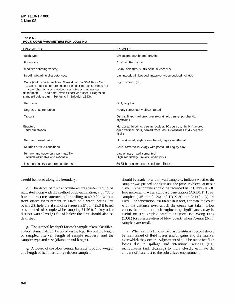
EM 1110-1-40001 Nov 98
4-8
Table 4-2ROCK CORE PARAMETERS FOR LOGGING
PARAMETER EXAMPLE
Rock type Limestone, sandstone, granite
Formation Anytown Formation
Modifier denoting variety Shaly, calcareous, siliceous, micaceous
Bedding/banding characteristics Laminated, thin bedded, massive, cross bedded, foliated
Color (Color charts such as Munsell or the GSA Rock Color Chart are helpful for describing the color of rock samples. If a color chart is used give both narrative and numericaldescription and note which chart was used. Suggestedstandard colors can be found in Spigolon 1993).
Light brown: (lBr)
Hardness Soft, very hard
Degree of cementation Poorly cemented, well cemented
Texture Dense, fine-, medium-, coarse-grained, glassy, porphyritic,crystalline
Structure and orientation
Horizontal bedding, dipping beds at 30 degrees, highly fractured,open vertical joints, healed fractures, slickensides at 45 degrees,fissile
Degree of weathering Unweathered, slightly weathered, highly weathered
Solution or void conditions Solid, cavernous, vuggy with partial infilling by clay
Primary and secondary permeability, include estimates and rationale
Low primary; well cementedHigh secondary: several open joints
Lost core interval and reason for loss 50-51 ft, noncemented sandstone likely
should be noted along the boundary.
o. The depth of first encountered free water should beindicated along with the method of determination; e.g., “37.6ft from direct measurement after drilling to 40.0 ft”; “40.1 ftfrom direct measurement in 60-ft hole when boring leftovernight, hole dry at end of previous shift”; or “25.0 ft basedon saturated soil sample while sampling 24-26 ft.” Any otherdistinct water level(s) found below the first should also bedescribed.
p. The interval by depth for each sample taken, classified,and/or retained should be noted on the log. Record the lengthof sampled interval, length of sample recovery, and thesampler type and size (diameter and length).
q. A record of the blow counts, hammer type and weight,and length of hammer fall for driven samplers
should be made. For thin wall samplers, indicate whether thesampler was pushed or driven and the pressure/blow count perdrive. Blow counts should be recorded in 150 mm (0.5 ft)foot increments when standard penetration (ASTM D 1586)samplers ( 35 mm [1-3/8 in.] ID X 50 mm [2 in.] OD) areused. For penetration less than a half foot, annotate the countwith the distance over which the count was taken. Blowcounts, in addition to their engineering significance, may beuseful for stratigraphic correlation. (See Hsai-Wong Fang(1991) for interpretation of blow counts when 75-mm (3-in.)samplers are used).
r. When drilling fluid is used, a quantitative record shouldbe maintained of fluid losses and/or gains and the intervalover which they occur. Adjustment should be made for fluidlosses due to spillage and intentional wasting (e.g.,recirculation tank cleaning) to more closely estimate theamount of fluid lost to the subsurface environment.
EM 1110-1-40001 Nov 98
4-9
s. Record the drilling fluid pressures typically usedduring all drilling operations (aqueous and pneumatic) and thedriller's comments on drillability, drill speed, down pressure,rotation speed, etc.
t. Note the total depth of drilling and sampling on thelog.
u. Record significant color changes in the drilling fluidreturn, even when intact soil samples or rock core are beingobtained. Include the color change (from and to), depth atwhich change occurred, and a lithologic description of thecuttings before and after the change.
v. Soil gas readings, if taken, should be recorded on thelog. Each notation should include interval sampled andreading. A general note on the log should indicate metermanufacturer, model, serial number, and calibration material. If several meters are used, key the individual readings to thespecific meter.
w. Special abbreviations used on a log and/or welldiagram should be defined in the log/diagram where used.
EM 1110-1-40001 Nov 98
Chapter 5Monitoring Well Installation
5-1. General
A monitoring well is a device designed for the acquisitionof groundwater samples that represent the chemical qualityof the aquifer adjacent to the screened interval, unbiased bythe well materials and installation process, and whichprovides access to measure the potentiometric surface forthat screened interval. The screened interval consists ofthat portion of the device that is directly open (e.g.,horizontally adjacent) to the host aquifer by way ofopenings in the well casing (hereafter called the “screen”)AND indirectly open (e.g., vertically adjacent) to theaquifer by way of the filter pack (or other permeablematerial) extending below and/or above the screen. Whilethe maximum length of the screened interval is fixed for agiven well (by the length of the filter pack), the effective orfunctional length may vary with water table fluctuations orsampling techniques. Additional guidance on monitoringwell installation may be found in ASTM D 5092.
5-2. Well Clusters
Each monitoring well is a mechanism through which toobtain a representative sample of groundwater and, tomeasure the potentiometric surface in that well. To helpensure this representation in the case of well clusters, eachwell of a cluster should be installed in a separate boring.Multiple well placements in a single boring are too difficultfor effective execution and evaluation to warrant singlehole usage.
5-3. Well Screen Usage
Each overburden well should have a screen, as per Figure5-1, 5-2, or 5-3 (or of a technically equivalent constructionas in ASTM D 5092). Under normal conditions, the extraeffort for screen installation in bedrock wells can be morethan offset by the assurance of an unobstructed opening tothe required depth during repeated usage. When conditionspermit, and when allowed by state or local law, an open,unscreened well may be constructed in firm stable bedrock.However, well integrity and consistent access to theoriginal sampled interval during prolonged monitoringmust be maintained.
5-4. Beginning Well Installation
a. The installation of each monitoring well should
begin within 12 hours of boring completion for holesuncased or partially cased with temporary drill casing.Installation should begin within 48 hours in holes fullycased with temporary drill casing. Once installation hasbegun, no breaks in the installation process should be madeuntil the well has been grouted and drill casing removed.Anticipated exceptions should be requested in writing bythe FDO to the FA prior to drilling. Data to include in thisrequest are:
(1) Well(s) in question;
(2) Circumstances; and
(3) Recommendations and alternatives.
b. In cases of unscheduled delay such as personalinjury, equipment breakdowns, or sudden inclementweather or scheduled delays such as borehole geophysics,no advance approval of delayed well installation should beneeded. In those cases, resume installation as soon aspracticable. However, partially completed borings shouldbe properly secured during periods of drilling inactivity topreclude the entry of foreign materials or unauthorizedpersonnel to the boring. In cases where a partially casedhole into bedrock is to be partially developed prior to wellinsertion, the well installation should begin within 12 hoursafter this initial development.
c. Temporary casing and hollow stem augers may bewithdrawn from the boring prior to well installation if thepotential for cross-contamination is not likely and if theborehole walls will not slough during the time required forwell installation. This procedure is usually successful infirm clays and in bedrock that is not intensely fractured orhighly weathered.
d. If the borehole will not remain stable long enoughto complete placement of all necessary well materials intheir proper position, it may be necessary to install some orall of the well materials prior to removal of the casing orhollow stem augers. In this situation, the hollow stemaugers or casing should have an inside diameter sufficientto allow the installation of the prescribed diameter screenand casing plus annular space for a pipe through which toplace the filter pack and grout.
e. Any materials, especially soils, blocking thebottom of the drill casing or hollow stem auger should bedislodged and removed from the casing prior to wellinsertion. This action both reduces the potential for cross--contamination and makes well installation easier.
5-l
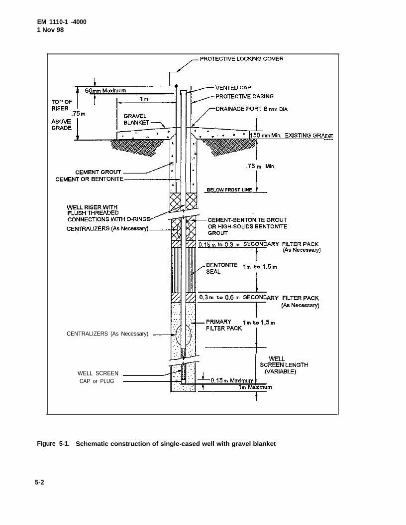
EM 1110-1 -40001 Nov 98
CENTRALIZERS (As Necessary)
WELL SCREENCAP or PLUG
Figure 5-1. Schematic construction of single-cased well with gravel blanket
5-2
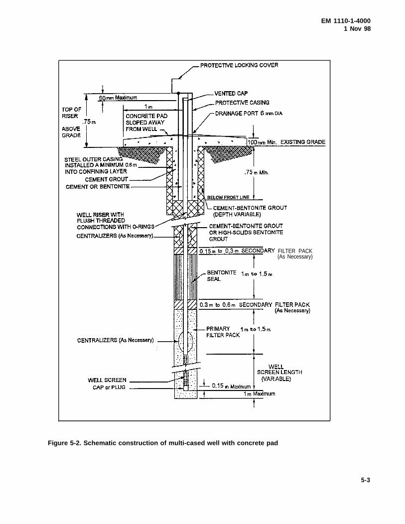
EM 1110-1-4000
FILTER PACK(As Necessary)
1 Nov 98
Figure 5-2. Schematic construction of multi-cased well with concrete pad
5-3
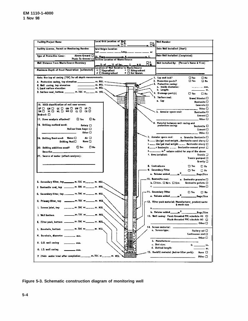
EM 1110-1-40001 Nov 98
Figure 5-3. Schematic construction diagram of monitoring well
5-4
Fadlity{Projed Name
Facility Ucense, Permit or M~Jnitoring Humber Grid Ori9in Location Date Well Installed (Start)
------------,.,..--::---:-=I lot.----- ___ Long. __ ---- or Type of Protedln '""'' Abon-Gr.,und 0 St. Plane m. N. Date Well Installed (Completed)
I-==~-~~~~~"!'!"',..;.R.;.u~sh~-T.;.o-:·-Gr_o_u_n_d.;:D=iSectlon Location of Waste/Sour<e Well Distance From Waote/Source Boundary
D. Surface leal, bottom ___ m. TOC or ___ m. MSL
16. uses classification of ... u near screen:
GPO GMO GCO GWO SWO SPO SM 0 SC 0 ML 0 MH 0 CL 0 CH 0 Bedr~Jck 0
17. Sieve analysis attached? DYes 0Ho
18. Drilling method used: Rotary 0
Hollow Stem Auger 0 Other 0
9. Drilling fluid used: Water D Drilling MudD
AirO HoneD
ZO. Drilling additiYu used? DYes DNo Dncribo ____________ _
21. Source of water (attach analysis):
E. Secondary filter, top ___ m. TOC or ___ m.
F. Bentonite seal, top ---m. TOC or ___ m.
G. Secondary filter, top.--- m. TOC or ___ m.
H. Primary filter, top ---m. TOC or ___ m.
Screen j~Jint, top
J. Well bottom ___ m. TOC "'---m.
K. Alter pack, bottom ---m. TOC .,r ___ m.
L Borehole, botlom ___ m. TDC or ___ m.
M. Borehole, diameter mm.
N. 0.0. well casln9 ___ mm.
0. I.D. well casing ---mm.
Well Installed By: (Person's Name i Firm)
I. Cap and lock? Protective posts?
3. Protective ceslng: a. Inside diameter: b. Length:
4. Drainage port(s)
5. Sanfau seal: •• Cap
DYes ClNo Cl Yes Cl No
---mm. ____ m.
0 Yes Cl No
Gravel blanket 0 Bentonite 0 Conue1o Cl
------------------------ OtherD b. Annular space seal: Bentonih Cl CementO
____________ Other 0
Material between well casing and protective casing: Bentonite 0
CementO -----------------------~herO
7. Annular space seal: a. Granular Bentonite 0 b, __ Lbs/gal mud weight •• Bentonile•sand slurry 0 c.-- Lbs/gal mud weight ......... Bentonite slurry 0 d.--~ Bentonite .......... Bentonite-cement grout 0
•·----- m:' volume added for any of the abo•• f. How installed: Tremie 0
Tremie pumped 0 Gravity 0
8. Centrallurs D Y.. 0 No
9. Secondary Filter 0 Yu 0 Ho a. Volume added__,. 3 _____ Bags/Size
10. Bentonite seal: a. Bentonite granules 0 b. 0 \l,ln. 0 ~ln. 0 \f,ln. Bentonite pellets 0
c.------------------ Othor 0
11. Secondary Riter Cl Yes 0 No a. Volume added__m 3 ______ B•gs/Sin
1Z. Alter pack material: Manufacturer, product name i mesh siu
··-------------------------------b. Volume added__m3 Bags/Sire
13. Well casing: Flush threaded PVC schedule 40 0 flush threaded PVC schedule 80 0
---------------------- Other 0 14. Sueen material:
a. Streon type: Factory cut 0 Continuous $lot 0
--------------------------OtherCl b. Manufadwer _______ _
'· Slot size: 0. in. d. Slotted length: ---m.
15. Backfill material (below filter pack): None 0
EM 111 0-1-40001 Nov 98
f. Once begun, well installation should not be inter-rupted due to the end of the driller’s work shift, darkness,weekend, or holiday.
g. If possible, the FDO should ensure that allmaterials and equipment for drilling and installing a givenwell are available and onsite prior to drilling that well.The FDO should have all equipment and materials onsiteprior to drilling and installing any well if the total welldrilling and installation effort is scheduled to take 14 daysor less. For longer schedules, the FDO should ensure thatthe above-mentioned materials needed for at least 14 daysof operation are onsite prior to well drilling. The balanceof materials should be in transit prior to well drilling.Any site-specific factors that preclude the availability ofneeded secure storage areas should be identified andresolved in the drilling plan.
5-5. Screens, Casings, and Fittings
a. All well screens and well casings should be free offoreign matter (e.g., adhesive tape, labels, soil, grease, etc.)and washed with approved water prior to use. Prewashingmay not be necessary if the materials have been packagedby the manufacturer and have their packaging intact up tothe time of installation. Pipe nomenclature stamped orstenciled directly on the well screen and/or blank casingwithin and below the bentonite seal should be removed bymeans of SANDING, unless removable in approved water.Solvents, except approved water, should NOT be used forremoval of marking. Washed screens and casings shouldbe stored in plastic sheeting until immediately prior toinsertion into the borehole.
b. Bottoms of well screens should be placed no morethan 1 m (3 ft) above the bottom of the drilled borehole. Ifsignificant overdrilling is required (as for determiningstratigraphy), a pilot boring should be used. The intent hereis to narrow the interval of aquifer being sampled, limit thepotential for stagnant or no-flow areas near the screen, andpreclude unwanted backfill materials (e.g., grout orbentonite) from entering or passing through the interval tobe screened and sampled. The casing/screen should besuspended from the surface and should not rest on thebottom of the borehole during installation of the filter packand annular seal.
c. All screen bottoms should be securely fitted with athreaded cap or plug of the same composition as the screen.This cap/plug should be within 150 mm (0.5 ft) of the openportion of the screen. No solvents or glues should bepermitted for attachment.
d. Silt or sediment traps (also called cellars, tail pipes,or sumps) should NOT be used. A silt trap is a blanklength of casing attached to and below the screen. Trapusage fosters a stagnant, turbid environment which couldinfluence analytical results for trace concentrations.
e. The top of each well should be level such that thedifference in elevation between the highest and lowestpoints on the top of the well casing or riser should be lessthan or equal to 6 mm (0.02 ft).
f. The borehole should be of sufficient diameter topermit at least 50 mm (2 in.) of annular space between theborehole wall and all sides of the well (centered riser andscreen). When telescoping casings (one casing withinanother), the full 50 mm (2-in.) annulus may not be prac-tical or functional. In this case, a smaller spacing may beacceptable, depending on site specifics.
g. Well screen lengths may be a function of hydro-stratigraphy, temporal considerations, environmental set-ting, analytes of concern, and/or regulatory mandate.Screen lengths should be specified in the drilling plan.
h. The actual inside diameter of a nominally sizedwell is a function of screen construction and the wallthickness/schedule of both the screen and casing. In thecase of continuously wound screens, their interior support-ing rods may reduce the full inside diameter. This con-sideration is critical when planning the sizes for pumps,bailers, surge devices, etc.
i. When physical or biological screen clogging isanticipated, the larger open-area per unit length of contin-uously wound screens has an advantage over the slottedvariety.
5-6. Granular Filter Pack
a. When artificial filter packs are used, a tremie pipefor filter pack placement is recommended, especially whenthe boring contains drilling fluid or mud. A record shouldbe maintained of the amount of water used to place thefilter pack, which should be added to the volume of waterto be removed during well development.
b. The filter pack should extend from the bottom ofthe boring to 1 to 1.5 m (3 to 5 ft) above the top of thescreen unless otherwise specified in the drilling plan. Thisextra filter allows for settlement (from infiltration andcompaction) of the filter pack during development andrepeated sampling events. The additional filter helps to
5-5
EM 1110-l-40001 Nov 98
maintain a separation between the bentonite seal and wellscreen.
c. Sometimes, depending on the gradation of theprimary filter pack and the potential for grout intrusion intothe primary filter pack, a secondary filter pack may beinstalled above the primary filter pack to prevent theintrusion of the bentonite grout seal into the primary filterpack. To be effective, the secondary filter should extend 0.3to 0.6 m (1 to 2 ft) above the primary filter pack.
d. The final depth to the top of the granular filtershould be directly measured (by tape or rod) and recorded.Final depths should not be estimated, for example, as basedon volumetric measurements of placed filter.
5-7. Bentonite Seals
a. Bentonite seals, especially those set in water,should typically be composed of commercially availablepellets. Pellet seals should be 1 to 1.5 m (3 to 5 ft) thick asmeasured immediately after placement without allowancefor swelling. Granular bentonite may be an alternate if theseal is set in a dry condition. Tremie pipes are notrecommended.
6. Slurry seals can be used when the seal location istoo far below water to allow for pellet or containerized-bentonite placement or within a narrow well-boreholeannulus. Typically, the specific gravity of cement groutplaced atop the slurry seal will be greater than that of theslurry. Therefore, the intent to use a slurry seal should bedetailed in the drilling plan, and details should include adiscussion of how the grout will be precluded frommigrating through the slurry. Slurry seals should have athick, batter-like (high viscosity) consistency with aplacement thickness of 1 to 1.5 m (3 to 5 ft). Typically,only high-solids bentonite grouts are used that consist of ablend of powdered bentonite and fresh water mixed to aminimum 20 percent solids by weight of pumpable slurrywith a density of 9.4 pounds per gallon or greater.
c. In wells designed to monitor possible contaminationin firm bedrock, the bottom of the bentonite seal should belocated at least 1 m (3 ft) below the top of firm bedrock, asdetermined by drilling. “Firm bedrock” refers to thatportion of solid or relatively solid, moderately tounweathered bedrock where the frequency of loose andfractured rock is markedly less than in the overlying, highlyweathered bedrock. Special designs will be needed tomonitor contamination in fractured bedrock. Guidance ondesign of ground-water monitoring systems in karst andfractured-rock aquifers may be found in ASTM D 5717.
d. The final depth to the top of the bentonite sealshould be directly measured (by tape or rod) and recorded.Final depths should not be estimated, as, for example,based on volumetric measurements of placed bentonite.
e. Numerous opinions have been expressed regardingbentonite hydration time, bentonite placement proceduresunder water versus in a dry condition, and the potentialinstallation delays and other consequences caused by thesefactors. By not allowing sufficient time for the bentoniteseal to hydrate and form a low permeable seal, groutmaterial could infiltrate into the bentonite seal and possiblyinto the filter pack. It is recommended waiting a minimumof 3 to 4 hours for hydration of bentonite pellets, or tabletswhen cement grout is used above the bentonite seal. Ifbentonite chips are used, the minimum hydration timecould be twice as long. Normally chips should only be usedif it is necessary to install a seal in a deep water column.Because of their high moisture content and slow swellingtendencies, chips can be dropped through a water columnmore readily than a material with a low moisture content,such as pellets or tablets. Bentonite chips should not beplaced in the vadose zone. A 1 m (3 ft) minimum bentonitepellet seal must be constructed to protect the screen andfilter pack from downhole grout migration. When installinga bentonite seal in the vadose zone (the zone above thewater table), water should be added to the bentonite for it toproperly hydrate. The amount of water required isdependent on the formation. It is recommended that thebentonite seal be placed in 0.15 to 0.3 m (6 in to 1 ft) lifts,with each lift hydrated for a period of 30 minutes. Thismethod will assure that the bentonite seal is well hydratedand accomplish its intended purpose. A 0.15 to 0.3 m (6 in.to 1 ft) layer of fine to medium sand (secondary filter pack)placed atop the bentonite seal may further enhance barrierresistance to downward grout migration.
5-8. Grouting
All prescribed portions of grout material should be com-bined in an aboveground rigid container and mechanically(not manually) blended to produce a thick, lump-freemixture throughout the mixing vessel. The mixed groutshould be placed around the monitoring well as follows.
a. The grout should be placed from within a rigid sidedischarge grout pipe located just over the top of the seal.The grout or tremie pipe should be decontaminated prior touse.
b. Prior to exposing any portion of the borehole abovethe seal by removal of any drill casing (to include hollow-stem augers), the annulus between the drill casing and well
5-6
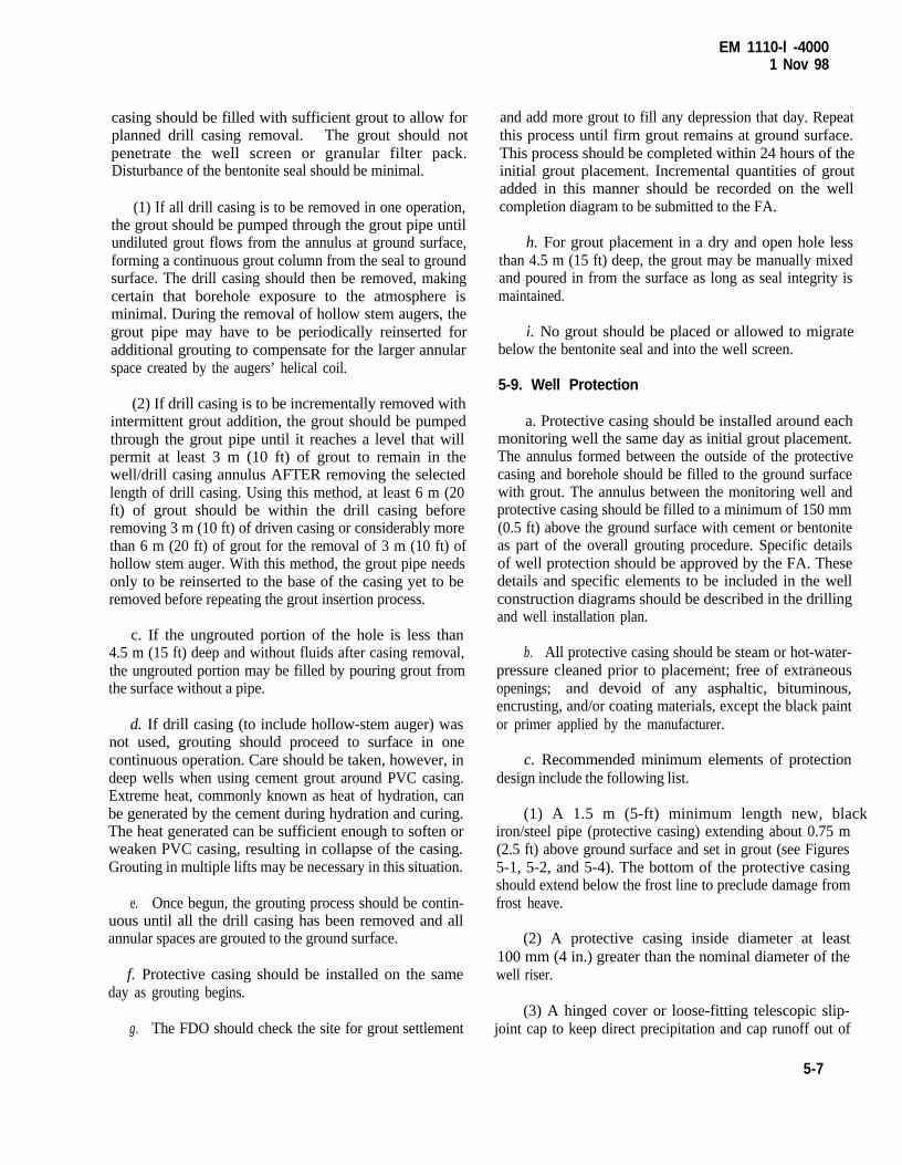
EM 1110-l -40001 Nov 98
casing should be filled with sufficient grout to allow forplanned drill casing removal. The grout should notpenetrate the well screen or granular filter pack.Disturbance of the bentonite seal should be minimal.
(1) If all drill casing is to be removed in one operation,the grout should be pumped through the grout pipe untilundiluted grout flows from the annulus at ground surface,forming a continuous grout column from the seal to groundsurface. The drill casing should then be removed, makingcertain that borehole exposure to the atmosphere isminimal. During the removal of hollow stem augers, thegrout pipe may have to be periodically reinserted foradditional grouting to compensate for the larger annularspace created by the augers’ helical coil.
(2) If drill casing is to be incrementally removed withintermittent grout addition, the grout should be pumpedthrough the grout pipe until it reaches a level that willpermit at least 3 m (10 ft) of grout to remain in thewell/drill casing annulus AFTER removing the selectedlength of drill casing. Using this method, at least 6 m (20ft) of grout should be within the drill casing beforeremoving 3 m (10 ft) of driven casing or considerably morethan 6 m (20 ft) of grout for the removal of 3 m (10 ft) ofhollow stem auger. With this method, the grout pipe needsonly to be reinserted to the base of the casing yet to beremoved before repeating the grout insertion process.
c. If the ungrouted portion of the hole is less than4.5 m (15 ft) deep and without fluids after casing removal,the ungrouted portion may be filled by pouring grout fromthe surface without a pipe.
d. If drill casing (to include hollow-stem auger) wasnot used, grouting should proceed to surface in onecontinuous operation. Care should be taken, however, indeep wells when using cement grout around PVC casing.Extreme heat, commonly known as heat of hydration, canbe generated by the cement during hydration and curing.The heat generated can be sufficient enough to soften orweaken PVC casing, resulting in collapse of the casing.Grouting in multiple lifts may be necessary in this situation.
e. Once begun, the grouting process should be contin-uous until all the drill casing has been removed and allannular spaces are grouted to the ground surface.
f. Protective casing should be installed on the sameday as grouting begins.
g. The FDO should check the site for grout settlement
and add more grout to fill any depression that day. Repeatthis process until firm grout remains at ground surface.This process should be completed within 24 hours of theinitial grout placement. Incremental quantities of groutadded in this manner should be recorded on the wellcompletion diagram to be submitted to the FA.
h. For grout placement in a dry and open hole lessthan 4.5 m (15 ft) deep, the grout may be manually mixedand poured in from the surface as long as seal integrity ismaintained.
i. No grout should be placed or allowed to migratebelow the bentonite seal and into the well screen.
5-9. Well Protection
a. Protective casing should be installed around eachmonitoring well the same day as initial grout placement.The annulus formed between the outside of the protectivecasing and borehole should be filled to the ground surfacewith grout. The annulus between the monitoring well andprotective casing should be filled to a minimum of 150 mm(0.5 ft) above the ground surface with cement or bentoniteas part of the overall grouting procedure. Specific detailsof well protection should be approved by the FA. Thesedetails and specific elements to be included in the wellconstruction diagrams should be described in the drillingand well installation plan.
b. All protective casing should be steam or hot-water-pressure cleaned prior to placement; free of extraneousopenings; and devoid of any asphaltic, bituminous,encrusting, and/or coating materials, except the black paintor primer applied by the manufacturer.
c. Recommended minimum elements of protectiondesign include the following list.
(1) A 1.5 m (5-ft) minimum length new, blackiron/steel pipe (protective casing) extending about 0.75 m(2.5 ft) above ground surface and set in grout (see Figures5-1, 5-2, and 5-4). The bottom of the protective casingshould extend below the frost line to preclude damage fromfrost heave.
(2) A protective casing inside diameter at least100 mm (4 in.) greater than the nominal diameter of thewell riser.
(3) A hinged cover or loose-fitting telescopic slip-joint cap to keep direct precipitation and cap runoff out of
5-7
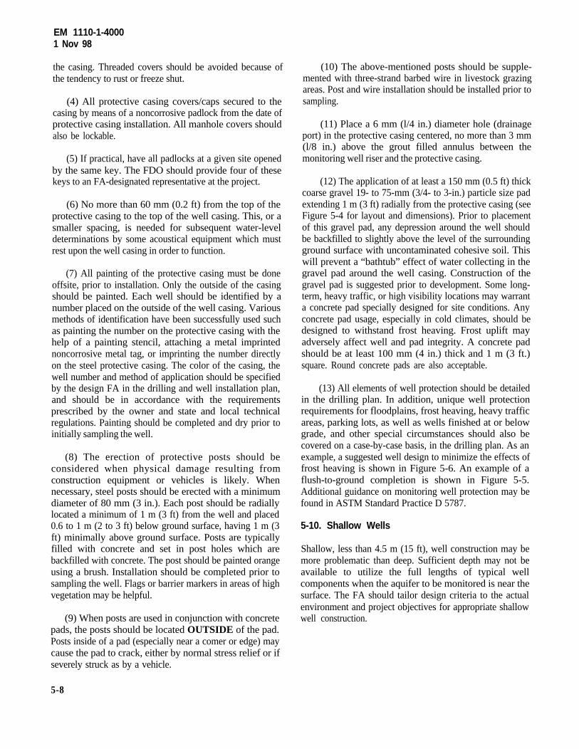
EM 1110-1-40001 Nov 98
the casing. Threaded covers should be avoided because ofthe tendency to rust or freeze shut.
(4) All protective casing covers/caps secured to thecasing by means of a noncorrosive padlock from the date ofprotective casing installation. All manhole covers shouldalso be lockable.
(5) If practical, have all padlocks at a given site openedby the same key. The FDO should provide four of thesekeys to an FA-designated representative at the project.
(6) No more than 60 mm (0.2 ft) from the top of theprotective casing to the top of the well casing. This, or asmaller spacing, is needed for subsequent water-leveldeterminations by some acoustical equipment which mustrest upon the well casing in order to function.
(7) All painting of the protective casing must be doneoffsite, prior to installation. Only the outside of the casingshould be painted. Each well should be identified by anumber placed on the outside of the well casing. Variousmethods of identification have been successfully used suchas painting the number on the protective casing with thehelp of a painting stencil, attaching a metal imprintednoncorrosive metal tag, or imprinting the number directlyon the steel protective casing. The color of the casing, thewell number and method of application should be specifiedby the design FA in the drilling and well installation plan,and should be in accordance with the requirementsprescribed by the owner and state and local technicalregulations. Painting should be completed and dry prior toinitially sampling the well.
(8) The erection of protective posts should beconsidered when physical damage resulting fromconstruction equipment or vehicles is likely. Whennecessary, steel posts should be erected with a minimumdiameter of 80 mm (3 in.). Each post should be radiallylocated a minimum of 1 m (3 ft) from the well and placed0.6 to 1 m (2 to 3 ft) below ground surface, having 1 m (3ft) minimally above ground surface. Posts are typicallyfilled with concrete and set in post holes which arebackfilled with concrete. The post should be painted orangeusing a brush. Installation should be completed prior tosampling the well. Flags or barrier markers in areas of highvegetation may be helpful.
(9) When posts are used in conjunction with concretepads, the posts should be located OUTSIDE of the pad.Posts inside of a pad (especially near a comer or edge) maycause the pad to crack, either by normal stress relief or ifseverely struck as by a vehicle.
(10) The above-mentioned posts should be supple-mented with three-strand barbed wire in livestock grazingareas. Post and wire installation should be installed prior tosampling.
(11) Place a 6 mm (l/4 in.) diameter hole (drainageport) in the protective casing centered, no more than 3 mm(l/8 in.) above the grout filled annulus between themonitoring well riser and the protective casing.
(12) The application of at least a 150 mm (0.5 ft) thickcoarse gravel 19- to 75-mm (3/4- to 3-in.) particle size padextending 1 m (3 ft) radially from the protective casing (seeFigure 5-4 for layout and dimensions). Prior to placementof this gravel pad, any depression around the well shouldbe backfilled to slightly above the level of the surroundingground surface with uncontaminated cohesive soil. Thiswill prevent a “bathtub” effect of water collecting in thegravel pad around the well casing. Construction of thegravel pad is suggested prior to development. Some long-term, heavy traffic, or high visibility locations may warranta concrete pad specially designed for site conditions. Anyconcrete pad usage, especially in cold climates, should bedesigned to withstand frost heaving. Frost uplift mayadversely affect well and pad integrity. A concrete padshould be at least 100 mm (4 in.) thick and 1 m (3 ft.)square. Round concrete pads are also acceptable.
(13) All elements of well protection should be detailedin the drilling plan. In addition, unique well protectionrequirements for floodplains, frost heaving, heavy trafficareas, parking lots, as well as wells finished at or belowgrade, and other special circumstances should also becovered on a case-by-case basis, in the drilling plan. As anexample, a suggested well design to minimize the effects offrost heaving is shown in Figure 5-6. An example of aflush-to-ground completion is shown in Figure 5-5.Additional guidance on monitoring well protection may befound in ASTM Standard Practice D 5787.
5-10. Shallow Wells
Shallow, less than 4.5 m (15 ft), well construction may bemore problematic than deep. Sufficient depth may not beavailable to utilize the full lengths of typical wellcomponents when the aquifer to be monitored is near thesurface. The FA should tailor design criteria to the actualenvironment and project objectives for appropriate shallowwell construction.
5-8
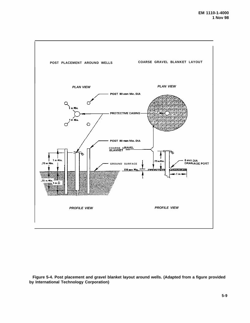
EM 1110-1-40001 Nov 98
POST PLACEMENT AROUND WELLS COARSE GRAVEL BLANKET LAYOUT
PLAN VIEW PLAN VIEW
COARSE G
GROUND SURFACE
PROFILE VIEW PROFILE VIEW
Figure 5-4. Post placement and gravel blanket layout around wells. (Adapted from a figure providedby International Technology Corporation)
5-9
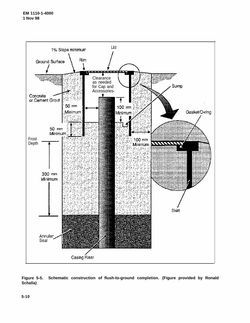
EM 1110-1-40001 Nov 98
FrostDepth
Clearanceas neededfor Cap andAccessories
Figure 5-5.Schalla)
Schematic construction of flush-to-ground completion. (Figure provided by Ronald
5-10
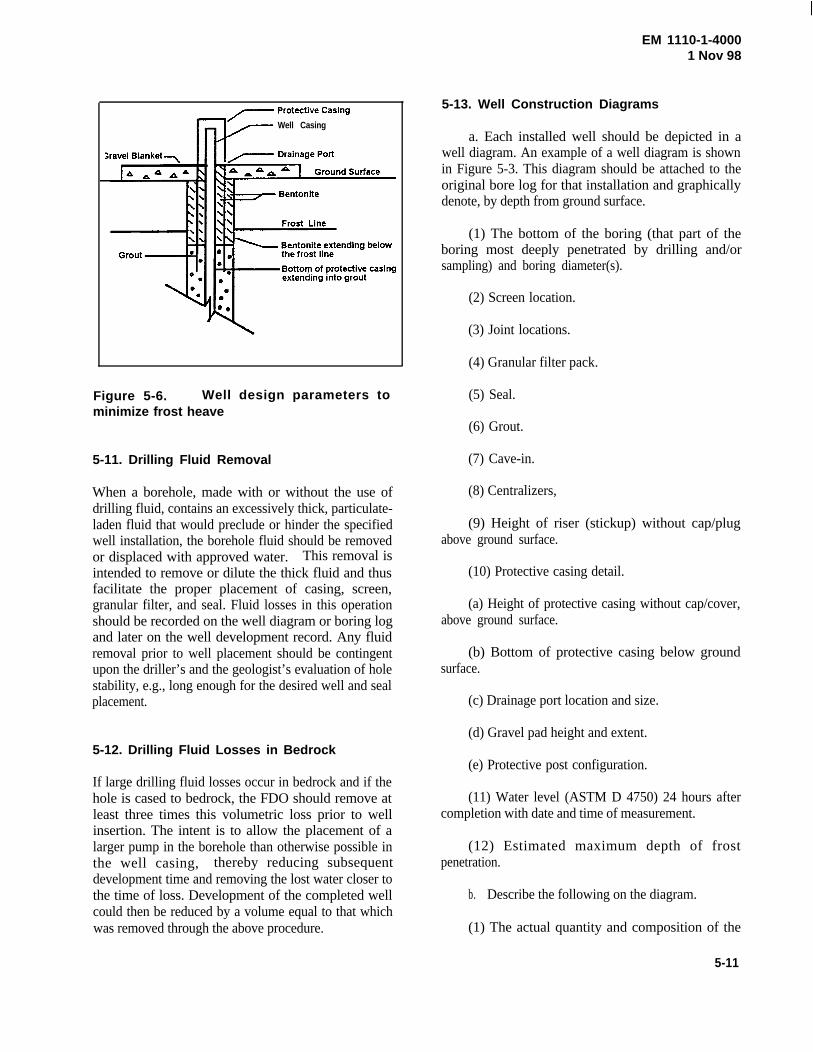
EM 1110-1-40001 Nov 98
Well Casing
Figure 5-6. Well design parameters tominimize frost heave
5-11. Drilling Fluid Removal
When a borehole, made with or without the use ofdrilling fluid, contains an excessively thick, particulate-laden fluid that would preclude or hinder the specifiedwell installation, the borehole fluid should be removedor displaced with approved water. This removal isintended to remove or dilute the thick fluid and thusfacilitate the proper placement of casing, screen,granular filter, and seal. Fluid losses in this operationshould be recorded on the well diagram or boring logand later on the well development record. Any fluidremoval prior to well placement should be contingentupon the driller’s and the geologist’s evaluation of holestability, e.g., long enough for the desired well and sealplacement.
5-13. Well Construction Diagrams
a. Each installed well should be depicted in awell diagram. An example of a well diagram is shownin Figure 5-3. This diagram should be attached to theoriginal bore log for that installation and graphicallydenote, by depth from ground surface.
(1) The bottom of the boring (that part of theboring most deeply penetrated by drilling and/orsampling) and boring diameter(s).
(2) Screen location.
(3) Joint locations.
(4) Granular filter pack.
(5) Seal.
(6) Grout.
(7) Cave-in.
(8) Centralizers,
(9) Height of riser (stickup) without cap/plugabove ground surface.
(10) Protective casing detail.
(a) Height of protective casing without cap/cover,above ground surface.
(b) Bottom of protective casing below groundsurface.
(c) Drainage port location and size.
(d) Gravel pad height and extent.5-12. Drilling Fluid Losses in Bedrock
(e) Protective post configuration.If large drilling fluid losses occur in bedrock and if thehole is cased to bedrock, the FDO should remove atleast three times this volumetric loss prior to wellinsertion. The intent is to allow the placement of alarger pump in the borehole than otherwise possible inthe well casing, thereby reducing subsequentdevelopment time and removing the lost water closer tothe time of loss. Development of the completed wellcould then be reduced by a volume equal to that whichwas removed through the above procedure.
(11) Water level (ASTM D 4750) 24 hours aftercompletion with date and time of measurement.
(12) Estimated maximum depth of frostpenetration.
b. Describe the following on the diagram.
(1) The actual quantity and composition of the
5-11
EM 1110-1-40001 Nov 98
grout, bentonite seals, and granular filter pack used foreach well.
(2) The screen slot size in millimeters (inches), slotconfiguration, total open area per meter (foot) ofscreen, outside diameter, nominal inside diameter,schedule/thickness, composition, and manufacturer.
(3) The material between the bottom of the boringand the bottom of the screen.
(4) The outside diameter, nominal inside diameter,schedule/thickness, composition, and manufacturer ofthe well casing.
(5) The joint design and composition.
(6) The centralizer design and composition.
(7) The depth and description of any permanentpump or sampling device. For pumps include thevoltage, phase requirements, and electrical plugconfiguration.
(8) The protective casing composition and nominalinside diameter.
(10) The dates and times for the start and com-pletion of well installation.
c. Each diagram should be attached to theoriginal boring log and submitted from the field to theFA.
d. Only the original well diagram and boring logshould be submitted to the FA. Carbon, typed, orreproduced copies should be retained by the FDO. Alegible copy of the well diagram may be used as a basefor the supplemental protection diagram.
e. Special abbreviations used on the wellcompletion diagram should be defined on the diagram.
(9) Special problems and their resolutions; e.g.,grout in wells, lost casing and/or screens, bridging,casing repairs or adjustments, etc.
5-12

EM 1110-1-4000 1 Nov 98
6-1
Chapter 6Well Development
6-1. General
Well development is the procedure that locally improves orrestores the aquifer's hydraulic conductivity and removeswell drilling fluids, muds, cuttings, mobile particulates, andentrapped gases from within and adjacent to a newlyinstalled well. The resulting inflow should be physically andchemically representative of that portion of the aquiferadjacent to the screened interval. The appropriatedevelopment method/procedure to use will vary according tothe hydrologic characteristics of the aquifer, the geologiccomposition of the screened interval, the drilling method,and the type of well completion. Of the various methodsavailable for use in developing wells in general, mechanicalsurging, pumping, backwashing, and bailing are bestsuited. Additional guidance on the development of ground-water monitoring wells may be found in ASTM StandardGuide D 5521.
6-2. Timing and Record Submittal
The final development of monitoring wells should beinitiated no sooner than 48 hours after or more than 7 daysbeyond the final grouting of the well. Predevelopment, orpreliminary development may be initiated before thisminimum 48 hour period. Preliminary development takesplace after the screen, casing and filter pack have beeninstalled, but before the annular seal is installed. Preliminarydevelopment is done in order to remove any mud cake thatmay be on the side of the borehole in a timely manner.Predevelopment is also recommended if the well is installedwith the intent of using the natural formation material as thefilter pack. Because this type of well design is based on theassumption that well development will remove a significantfraction of the formation materials adjacent to the wellscreen (therefore causing some sloughing in the borehole),developing the well after installing the annular seal mayresult in portions of the annular seal collapsing into thevicinity of the well screen. It is not good practice to wait anddevelop all the monitoring wells on a project after the lastone is complete. The record of well development should besubmitted to the FA.
6-3. Development Methods
A thorough discussion of monitoring well developmentmethods can be found in ASTM Standard Guide D 5521.
a. Mechanical Surging. Operation of a piston-like devicetermed a surge block affixed to the end of a length of drillrod, or drill stem, is a very effective development methodthat can be effective in all diameter of wells, even instratified formations having variable permeability. The up-and-down plunging action alternately forces water to flowinto and out of the well, similar to a piston in a cylinder. Theuse of a surge block can agitate and mobilize particulatesaround the well screen. Periods of surging should bealternated with periods of water extraction from the well sothat sediment, brought into the well, is removed. Surgingshould initially be gentle to assure that water can come intothe well and that the surge block is not so tight as to damagethe well pipe or screen. For short well screens (1.6 m (5 ft)or less) set in a homogeneous formation, the surge blockdoes not have to be operated within the screen interval.However, if the screened interval includes materials of highand low permeabilities, the block may have to be operatedgently within the screen.
b. Pumping. A commonly used development methodconsists of pumping a well at a higher rate than water will beextracted during purging or sampling events. Thisoverpumping, however, is usually only successful inrelatively non-stratified, clean-sand formations. Bypumping the well at a higher rate than expected duringsampling, the mobilized particulates may be removed,thereby providing a cleaner well for sampling.Overpumping should be supplemented with the use of abottom discharge/filling bailer, (for sediment removal). During development, water should be removed throughoutthe entire water column in the well by periodically loweringand raising the pump intake. A disadvantage of onlypumping the well is that the smaller soil grains of the filterpack may be bridged in the screen or in the filter pack, as thedirection of flow is only towards the screen. To overcomethis, overpumping is often used in conjunction withbackwashing or surging.
c. Backwashing. Backwashing is the reversal of waterflow in a well, causing soil particles to dislodge that mayhave become wedged in or bridged around the screen due tooverpumping of the well. Backwashing when supplementedwith overpumping, facilitates the removal of fine-grainedmaterials from the formation surrounding the borehole. Acommonly used backwashing procedure called “rawhiding”consists of starting and stopping the pump intermittently toallow the rising water in the well pipe to fall back into thewell. This backwashing procedure produces rapid changesin the pressure head within the well. If rawhiding is to beused, there cannot be a backflow prevention valve in thepump or eductor line. Another method of backwashing is topump water into the well in sufficient volume to maintain a
EM 1110-1-40001 Nov 98
6-2
head greater than that in the formation. This method ofbackwashing should only be done when the water pumpedinto the well is of known and acceptable chemistry. Theimpact of added water on in situ water quality should beevaluated and, this water should be removed by pumpingafter development is complete. This method ofbackwashing, not withstanding the quality of water pumpedinto the well, may not be allowed by local, state, or federalagencies. Do not use this method in cases where the waterpumped into the well is potentially contaminated.
d. Bailing. The use of bailers is an effective way ofmanually developing small diameter wells that have a highstatic water table or are relatively shallow in depth (<4.5 m(15 ft)). As the diameter of the bailer is commonly close tothe same diameter as the well screen, the bailer agitates thewater in the well in much the same manner as a surge block,but to a lesser extent. It is good practice to surge the wellusing the bailer for 10 to 20 minutes prior to beginningbailing. To have its most effective surging action, the bailershould be operated throughout the screened interval.Bottom loading bailers can extract sediment that has settledto the bottom of the well by rapid short upward/downmotions of the bailer at the bottom of the well which stir upthe sediment and take it into the bailer. Pumps may bereplaced by bottom filling bailers where well size or slowrecharge rates restrict pump usage. Bailers should not be leftinside the wells after development is completed. Suchstorage promotes accidental bailer release or loss down thewell and inhibits convenient and accurate water-levelmeasurements.
e. High-velocity hydraulic jetting. Another effectivemethod available for use in developing some monitoringwells, is high-velocity hydraulic jetting. This methodemploys several horizontal jets of water operated frominside the well screen so that high-velocity streams of waterexit through the screen and loosen fine-grained material anddrilling mud residue from the formation. The loosenedmaterial moves inside the well screen and can be removedfrom the well by concurrent pumping or by bailing. Becauseof the size of the equipment required, this method is moreeasily applied to wells of 100 mm (4 in.) or greaterdiameter. Jetting is particularly successful in developinghighly stratified unconsolidated formations, consolidatedbedrock wells, large-diameter wells, and natural formationwells. Jetting is generally simple to use, effectivelyrearranges and breaks down bridging in the filter pack, andeffectively removes mud cakes around screen. Thedisadvantage of using jetting even in ideal conditions is theintroduction of foreign water and possible contaminants intothe aquifer. Jetting is not effective in cases where slottedpipe is used for the screen. Jetting is much more effective
where continuous-wrap v-wire screens, having a greateropen area, are used.
f. Special Concerns.
(1) Where monitoring well installations are made informations that have low hydraulic conductivity, none of thepreceeding well development methods may be found to becompletely satisfactory. In this situation clean water can becirculated down the well casing, out through the well intakeand gravel pack, and up the open borehole prior toplacement of the grout or seal in the annulus. Relatively highwater velocities can be maintained, and the mud cake fromthe borehole wall will be broken down effectively andremoved. Flow rates should be controlled to prevent floatingthe gravel pack out of the borehole. Because of therelatively low hydraulic conductivity of geologic materialsoutside the well, a negligible amount of water will penetratethe formation being monitored. However, immediatelyfollowing the procedure, the well sealant should be installedand the well pumped to remove as much of the water used inthe development process as possible (Barcelona et al. 1985).Adding water to the well for flushing should only be done,however, when no better options are available. In some finegrained deposits vigorous development can be detrimental tothe well. If vigorous development is attempted in such wells,the turbidity of water removed from the well may actuallyincrease many times over. In some fine-grained formationmaterials, no amount of development will measurablyimprove formation hydraulic conductivity or the hydraulicefficiency of the well. Alternative sampling methods, such aslysimeters (ASTM D 4696), should be considered in lowconductivity formations.
(2) Drilling methods. The drilling process influences notonly development procedures but also the intensity withwhich these procedures must be applied. Typical problemsassociated with special drilling technologies that must beanticipated and overcome are: 1) When drilling an air rotaryborehole in rock formations, fine particulate matter typicallybuilds up on the borehole walls and plugs fissures, porespaces, bedding planes and other permeable zones. Thematter must be removed and the openings restored by thedevelopment process; 2) If casing has been driven or ifaugers have been used, the interface between the naturalformation and the casing or the auger flights are “smeared”with fine particulate matter that must subsequently beremoved in the development process; 3) If a mud rotarytechnique is used, a mud cake builds up on the borehole wallthat must be removed during the development process; and4) If there have been any additives, as may be necessary inmud rotary, cable tool or augering procedures, the
EM 1110-1-4000 1 Nov 98
6-3
development process must attempt to remove all of the fluidsthat have infiltrated into the natural formation (EPA/600/4-89/034). A comparison of the advantages and disadvantagesof various drilling methods is in Table 3-1.
6-4. Development Criteria
a. Development should proceed until the followingcriteria are met:
(1) Satisfaction of applicable federal, state, and localregulatory requirements. Some of these requirements mayspecify that development continue until the readings forsome indicator parameters like pH, conductivity,temperature, oxidation-reduction potential (ORP), dissolvedoxygen (DO), or turbidity have stabilized; e.g., vary within aspecified range. Stabilization is commonly considered tohave been achieved after all parameters have stabilized forthree successive readings. Generally three successivereadings should be within ±0.2 for pH, ±3% forconductivity, ±10 mV for oxidation-reduction potential(ORP), ±1 degree Celsius for temperature, and ±10% forturbidity and DO. In general the order of stabilization is pH,temperature, and conductivity, followed by ORP, DO andturbidity (Puls and Barcelona 1996).
(2) The well water is clear to the unaided eye and theturbidity of the water removed is at some specified level.Some regulators may require that the turbidity, as measuredin nephlometric turbidity units (NTUs), be less than 5 NTUs.It should be noted that natural turbidity levels in groundwater may exceed 10 NTUs. Turbidity is always the lastindicator parameter to stabilize. There are instances whereminimizing turbidity will result in a sample that is notrepresentative of the water that is moving through theformation. If the ground water moving through theformation is, in fact, turbid, or if there is free productmoving through the formation, then some criteria may causea well to be constructed such that the actual contaminant thatthe well was installed to monitor will be filtered out of thewater. Therefore, it is imperative that the design,construction and development of the monitoring well beconsistent with the objective of obtaining a sample that isrepresentative of conditions in the ground.
(3) The sediment thickness remaining within the well isless than 1 percent of the screen length or less than 30 mm(0.1 ft) for screens equal to or less than 3 m (10 ft) long.
(4) A minimum removal of three times the standingwater volume in the well (to include the well screen and
casing plus saturated annulus, assuming 30 percent annularporosity). IN ADDITION to the “three times the standingwater volume” criteria, further volumetric removal shouldbe considered as follows:
(a) For those wells where the boring was made withoutthe use of drilling fluid (mud and/or water), but water wasadded to the well during well installation, then three timesthe amount of any water unrecovered from the well duringinstallation should be removed (in addition to three times thestanding volume).
(b) For those wells where the boring was made orenlarged (totally or partially) with the use of drilling fluid(mud and/or water), remove three times the measured (orestimated) amount of total fluids lost while drilling, plusthree times that used for well installation (in addition to threetimes the standing volume).
(5) If the primary purpose of development is to rectifydamage done during drilling to the borehole wall and theadjacent formation, the time for development may be basedon the response of the well to pumping (ASTM D 4050). Animprovement in recovery rate of the well indicates that thelocalized reduction in hydraulic conductivity has beeneffectively rectified by development. A commonly usedmethod for determining hydraulic conductivity is theinstantaneous change in head, or slug test. The slug testmethod involves causing a sudden change in head in the welland measuring the water level response within the well.Head change can be induced by suddenly injecting orremoving a known quantity or “slug” of water into the well.However, instead of injecting a “slug” of water, a solid ormechanical slug of known volume should be used. Themechanical slug may be constructed of a section of weightedpipe, of known volume, capped on both ends. Water leveland elapsed-time data can be recorded with a data logger andpressure transducer. Both “rising heads” and “falling heads”are recorded. Guidance on conducting slug tests may befound in ASTM Standard D 4044.
b. Prior to placement of the seal, if the borehole containsan excessively thick, particulate-laden fluid which wouldhinder proper well installation, this fluid should be dilutedand/or flushed with clean water and purged from the well.Water should not be added to a well as part of developmentonce the initial bentonite seal atop the filter pack is placed. Itis essential that any water added to the well is of known andacceptable chemistry. The impact of added water on in situwater quality should be evaluated and removed afterdevelopment is complete.
EM 1110-1-40001 Nov 98
6-4
c. The use of air to develop a well SHOULD NOT beallowed. The introduction of air into a well enhances theoccurrence of chemical, physical, and biological changes tothe local aquifer system monitored by the well. Furthermore,procedures involving compressed air at HTW sites increasepotential exposure/health risks to site personnel from thevolatilization and misting of the aerated water. If airdevelopment is deemed the most appropriate method for asite, the above factors should be evaluated and mitigationprocedures documented in the drilling plan.
d. If any of the following circumstances occur, the FAshould be contacted for guidance:
(1) Well recharge so slow that the required volume ofwater cannot be removed during 48 consecutive hours ofdevelopment;
(2) Persistent water discoloration after the requiredvolumetric development; and
(3) Excessive sediment remaining after the requiredvolumteric removal.
6-5. Development-Sampling Break
Time should be allowed for equilibration of the well with theformation after development before sampling of the well isundertaken. Well development should be completed at least14 days before well sampling. The intent of this hiatus is toprovide time for the newly installed well and backfillmaterials to surficially equilibrate to their new environmentand for that environment to re-stabilize after the disturbanceof drilling. Though a significant volume of water may bepulled through the well during development, the well andgranular backfill surfaces over which this water passes arenot likely to be at chemical equilibrium with the aquifer.Intuitively, the hiatus allows time for that equilibrium to becreated, thereby enhancing the probability of the resultingsample to be more representative of the local aquifer. The14-day hiatus is a “rule-of-thumb,” unsubstantiated byrigorous scientific analysis. If a different value is proposedbased upon technical data or overall project considerations,such a change should be evaluated and, if deemedappropriate, implemented. Generally, high permeabilityformations require less time (e.g., several days) to equilibratethan low permeability formations (e.g., several weeks). TheFSP should state the amount of time that will be required topermit the equilibration of the monitoring well followingdevelopment and prior to sampling and the justification forselection of that time interval.
6-6. Development Water Sample
For each well, a 0.5 L (1-pint) sample of the last water to beremoved during development should be placed in a clearglass jar and labeled with well number and date. Nopreservation of these samples is required. Each sampleshould be individually agitated and immediately photo-graphed close-up by the FDO with a 35-mm camera andcolor print film, using a back-lit setup to show water clarity.These photos, minimally 125 mm x 175 mm (5 in. x 7 in.),individually identified with project name, well number, andphoto date, should be provided to the FA after all wells aredeveloped. The film negatives should be provided to the FAafter the FA has received the prints. The FDO shoulddispose of these water samples in the same manner as therest of the water removed during development.
6-7. Well Washing
Part of well development should include the washing of theentire well cap and the interior of the well casing above thewater table using only water from that well. The result ofthis operation will be a well casing free of extraneousmaterials (grout, bentonite, sand, etc.) inside the well capand blank casing, between the top of the well and the watertable. This washing should be conducted before and/orduring development, not after development.
6-8. Well Development Record
The following data should be recorded as part of develop-ment and submitted to the FA:
a. Project name, location.
b. Well designation, location.
c. Date(s) and time(s) of well installation.
d. Date(s) and time(s) of well development.
e. Static water level from top of well casing before and24 hours after development.
f. Quantity of mud/water:
(1) Lost during drilling.
(2) Removed prior to well insertion.
(3) Lost during thick fluid displacement.
EM 1110-1-4000 1 Nov 98
6-5
(4) Added during granular filter placement.
g. Quantity of fluid in well prior to development:
(1) Standing in well.
(2) Contained in saturated annulus (assume 30 percentporosity).
h. Field measurement of pH (ASTMs D1293 andD5464), conductivity (ASTM D1125), oxidation-reduction(redox) potential (ASTM D1498), dissolved oxygen(ASTMs D888 and D5462), turbidity (ASTM D1889), andtemperature (EPA Method 170.1) before, twice during, andafter development using an appropriate device and method.Field methods for these parameters can also be found inEPA 600/4-79/020, and Standard Methods.
i. Depth from top of well casing to bottom of well.
j. Screen length.
k. Depth from top of well casing to top of sedimentinside well, before and after development (from actualmeasurements at time of development).
l. Physical character of removed water, to includechanges during development in clarity, color, particulates,and any noted odor.
m. Type and size/capacity of pump and/or bailer used.
n. Description of surge technique, if used.
o. Height of well casing above ground surface (fromactual measurement at time of development).
p. Typical pumping rate.
q. Estimated recharge rate.
r. Quantity of fluid/water removed and time for removal(present both incremental and total values).
6-9. Potential Difficulties
Many difficulties may arise during development andpresample purging. Some are readily apparent but trou-blesome to resolve; e.g., a well that is easily pumped dry butslow to recharge or one that will not produce clear,particulate-free water. Other difficulties are not easilyobserved but may bias the analytical results, e.g., pulling-indistant parts of the aquifer in an effort to achieve arepetitively consistent field reading or aerating the aquiferadjacent to the well in a hurried attempt at well development.In addition, the unanticipated presence of dense (or light)nonaqueous phase liquids (NAPL) in the screened intervalwould affect the chemical homogeneity of that interval andhydrologic parameters derived from that well. Theanticipation, evaluation, and tentative solution for theseproblems should begin early in the formulation of eachdrilling plan.
EM 1110-1-40001 Nov 98
7-1
Chapter 7Well and Boring Acceptance Criteria
7-1. Well Criteria
Wells should be acceptable to the FA. Well acceptanceshould be on a case-by-case basis. The following criteriashould be used along with individual circumstances in theevaluation process.
a. The well and material placement should meet theconstruction and placement specifications of the drilling andwell installation plan unless modified by amendments.
b. Wells should not contain portions of drill casing oraugers unless they are specified in the drilling plan as per-manent casing.
c. All well casing and screen materials should be free ofany unsecured couplings, ruptures, or other physical break-age/defects before and after installation.
d. The annular material (filter pack, bentonite, and grout)of the installed well should form a continuous and uniformstructure, free of any detectable fractures, cracks, or voids.
e. Any casing or screen deformation or bending shouldbe minimal to allow the insertion and retrieval of the pumpand/or bailer optimally designed for that size casing, e.g., a 75mm (3-in.) pump in a 100 mm (4-in.) schedule 80, PVCcasing is optimal; a 50 mm (2-in.) pump in a 100 mm (4-in.)casing is not optimal.
f. All joints should be constructed to provide a straight,nonconstricting, and watertight fit.
g. Completed wells should be free of extraneous objectsor materials; e.g., tools, pumps, bailers, packers, excessivesediment thickness, grout, etc. This prohibition should notapply to intentionally installed equipment per drilling plan.
h. For those monitoring wells where the screen depth wasdetermined by the FDO, the well should have sufficient freewater at the time of the water-level measurement to obtain arepresentative groundwater level for that well. These samewells should have sufficient free water at the time of initialsampling, which is representative of the desired portion of theaquifer for the intended chemical analyses.
i. All boring logs, well diagrams, development records,topographic survey data, and related photographs andnegatives should have been completed per the drilling planand received by the FA.
j. Keys to the padlocks securing the well covers shouldbe in the possession of the FA and the FA project representa-tive prior to well acceptance.
7-2. Abandoned/Decommissioned Borings andWells
Borings not completed as wells should be abandoned/ de-commissioned per paragraph 3-14 of this manual.
7-3. Well and Boring Rejection
Wells and borings not meeting drilling plan criteria are sub-ject to rejection by the FA.

EM 1110-1-40001 Nov 98
8-1
Chapter 8Water Levels
8-1. Measurement Frequency and Coverage
The frequency of water-level measurement is project related. At a minimum, for those projects involving the installation ofany monitoring wells, at least one complete set of staticwater-level measurements should be made over a single,consecutive 10-to-12-hour period for all project-related wells,both newly installed and specified existing wells. These mea-surements should be taken at least 24 hours after developmentor sampling. Static levels in borings not converted to wellsshould be included if practical and technically appropriate. This set of measurements should include a notation for thepresence of any streams, lakes, and/or open water bodies(natural and man-made) within proximity, e.g., about 90 m(300 ft) of these wells. Elevation measurements of anysurface water bodies should be a consideration within thedrilling and well installation plan.
8-2. Vertical Control
The depth to groundwater should be measured and reported tothe nearest 3 mm (0.01 ft). Measurement should be madefrom the highest point on the rim of the well casing or riser(not protective casing). This same point on the well casingshould be surveyed for vertical control. The surveyed mark onthe top of the casing should be permanently marked with anotch cut in the casing to ensure that depth to water is alwaysmeasured from the same elevation. Surface water levelsshould be measured at least to the nearest 30 mm (0.1 ft)using an adjacent temporary or permanent survey marker asa datum for current and future reference.
8-3. Reporting and Usage
All water level data should be presented as elevations in tab-ular form. Where sufficient data points exist, the elevationsshould be contoured to denote flow directions, gradients, andany hydrological interconnections between aquifers andsurface water bodies.
8-4. Methods
Guidance on determining liquid levels in a borehole or moni-toring well may be found in ASTM D 4750.
EM 1110-1-40001 Nov 98
9-1
Chapter 9Topographic Survey
9-1. Licensing
All topographic survey efforts conducted under contractshould be certified by a surveyor with a current surveyor'slicense in the project state. Any licensing requirements withinthe project state for contract or Corps of Engineers surveyorsshould be determined by the FA.
9-2. Horizontal Control
Each boring and/or well installation should be topographicallysurveyed to determine its map coordinates referenced to eithera Universal Transverse Mercator (UTM) grid or the StatePlane Coordinate System (SPCS). These surveys should beconnected to the UTM or SPCS by third order, Class IIcontrol surveys in accordance with the Standards andSpecifications for Geodetic Control Networks (FederalGeodetic Control Committee 1984). If the project is in anarea remote from UTM or SPCS benchmarks and suchhorizontal control is not warranted, then locations measuredfrom an alternate system depicted on project plans maysuffice, at least on a temporary basis. All borings, wells,temporary and/or permanent markers should have an accuracyof "300 mm ("1 ft) within the chosen system.
9-3. Vertical Control
Elevations for the natural ground surface (not the top of thecoarse gravel blanket) and a designated point on the rim of theuncapped well casing (not protective casing) for eachbore/well site should be surveyed to within 3 mm ("0.01 ft)and referenced to the National Geodetic Vertical Datum of1929 (NGVD of 1929) or the North American VerticalDatum, 1988 Adjustment (NAVD 88). These surveys shouldbe connected by third order leveling to the NGVD of 1929 orNAVD 1988 in accordance with the Standards and
Specifications for Geodetic Control Networks. If the projectis in an area remote from NGVD benchmarks and suchvertical control is not warranted, then elevations measuredfrom a project datum may suffice, at least on a temporarybasis.
9-4. Field Data
The topographic survey should be completed as near to thetime of last well completion as possible. Survey field data (ascorrected), to include loop closures and other statistical datain accordance with the Standards and Specificationsreferenced above, should be provided to the FA. Closureshould be within the horizontal and vertical limits givenabove. These data should clearly be listed in tabular formincluding the coordinates (and system) and elevation (groundsurface and top of well) as appropriate, for all borings, wells,and reference marks. All permanent and semipermanentreference marks used for horizontal and vertical control,benchmarks, caps, plates, chiseled cuts, rail spikes, etc.,should be described in terms of their name, character, physicallocation, and reference value. These field data should becomepart of the project records maintained by the FA.
9-5. Geospatial Data Systems
Geospatial data is non-tactical data referenced either directlyor indirectly to a location on the earth. Geospatial dataidentifies the geographic location and characteristics ofnatural or constructed features and boundries on the earth.Monitoring wells and the data generated from them meetthese definitions and therefore must be documented accordingto the metadata standards cited in ER 1110-1-8156. ER 1110-1-8156 requires geospatial data to be documented using theFederal Geographic Data Committee Content Standards forDigital Geospatial Metadata. Guidance on geospatial datasystems (GDS) may also be found in EM 1110-1-2909 andASTM Standard Specification D 5714.
EM 1110-1-40001 Nov 98
10-1
Chapter 10Borehole Geophysics
10-1. Usage and Reporting
The use of geophysical techniques, if required, should bespecified in the drilling plan. In the absence of this speci-fication, the FDO should consider these techniques for site-specific applicability to enhance the technical acuity and cost-effectiveness of its efforts. Special applications may be usefulin unexploded ordnance detection, disturbed area delineation,contaminant detection, depth to bedrock determination, burieddrum detection, borehole and well logging, etc. Whenapproved for use, geophysical techniques should
be discussed in the drilling plan to include the purpose; par-ticular method(s) and equipment; selection rationale; physi-cal and procedural assumptions; limitations (theoretical andsite specific); resolution; accuracy; and quality control. Safety aspects of geophysical applications should be includedin the safety plan, especially for those areas where inducedelectrical currents or seismic waves could detonate unex-ploded ordnance or other explosive materials.
10-2. Methods
General geophysical methodology is covered in EM 1110-1-1802. Geophysical techniques applied to HTRW studies arefound in USEPA 625/R-92/007, 600/2-87/078, 600/7-84/064,and in Benson, Glaccum, and Noel (1982). Additionalguidance on planning and conducting borehole geophysicallogging can be found in ASTM Standard Guide D 5753.
EM 1110-1-40001 Nov 98
11-1
Chapter 11Vadose Zone Monitoring
11-1. Usage and Reporting
Data acquisition from the vadose (unsaturated) zone should beaddressed on a case-by-case basis. The use of lysimeters in asilica flour matrix, soil-gas monitors, and analysis of bulk soilsamples are mechanisms which may be employed.
When vadose zone monitoring is proposed,the drilling planshould include the purpose; particular method(s) and equip-ment; selection rationale; physical and procedural assump-tions; limitations (theoretical and site-specific); quality con-trol; and any analytical variances from the current USACEprotocol.
11-2. Methods
Guidance on vadose zone monitoring may be found in ASTM Standard Guides D 4696 and D 5126. A general dis-cussion of vadose monitoring can be found in Everett, Wilson,and Hoylman (1984).
EM 1110-1-40001 Nov 98
12-1
Chapter 12Data Management System
12-1. Benefits
The use of a computerized system will enhance reportingprocedures by means of intra-report consistency, reduction ofeditorial review, broadening of graphical capabilities, andease of data retrieval for project review and inter-projectcomparisons. Each FA is encouraged to utilize acomputerized data management system for technical data.
12-2. Assistance Sources
Several existing systems are available for utilization byindividual FAs. New systems are also being developed at theDOD level to combine existing systems and reduceredundancy in data reporting systems. Guidance on boringlog data management may be found in the USACEWaterways Experiment Station contract report GL-93-1. Assistance can be obtained from the HTRW CX, at CENWO-HX-G.
12-3. Geospatial Data Systems
Geospatial data is non-tactical data referenced either directlyor indirectly to a location on the earth. Geospatial dataidentifies the geographic location and characteristics ofnatural or constructed features and boundries on the earth.Monitoring wells, and the data generated from them, meetthese definitions and therefore must be documented accordingto the metadata standards cited in ER 1110-1-8156. ER 1110-1-8156 requires geospatial data to be documented using theFederal Geographic Data Committee Content Standards forDigital Geospatial Metadata. Guidance on geospatial datasystems (GDS) may also be found in EM 1110-1-2909 andASTM D 5714.
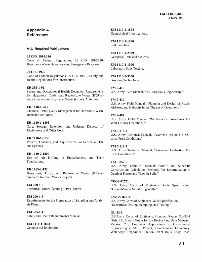
EM 1110-1-4000 1 Nov 98
A-1
Appendix AReferences
A-1. Required Publications
29 CFR 1910.120Code of Federal Regulations, 29 CFR 1910.120,Hazardous Waste Operations and Emergency Response.
29 CFR 1926Code of Federal Regulations, 29 CFR 1926, Safety andHealth Regulations for Construction.
ER 385-1-92Safety and Occupational Health Document Requirementsfor Hazardous, Toxic, and Radioactive Waste (HTRW)and Ordnance and Explosive Waste (OEW) Activities.
ER 1110-1-263Chemical Data Quality Management for Hazardous WasteRemedial Activities.
ER 1110-1-1803Care, Storage, Retention, and Ultimate Disposal ofExploratory and Other Cores.
ER 1110-1-8156Policies, Guidance, and Requirements For Geospatial Dataand Systems.
ER 1110-2-1807Use of Air Drilling in Embankments and TheirFoundations.
ER 1165-2-132Hazardous, Toxic, and Radioactive Waste (HTRW)Guidance for Civil Works Projects.
EM 200-1-2 Technical Project Planning (TPP) Process.
EM 200-1-3Requirements for the Preparation of Sampling and Analy-sis Plans.
EM 385-1-1Safety and Health Requirements Manual.
EM 1110-1-1802Geophysical Exploration.
EM 1110-1-1804Geotechnical Investigations.
EM 1110-1-1906Soil Sampling.
EM 1110-1-2909Geospatial Data and Systems.
EM 1110-2-1906Laboratory Soils Testing.
EM 1110-2-3506Grouting Technology.
FM 5-410U.S. Army Field Manual, “ Military Soils Engineering.”
FM 5-430U.S. Army Field Manual, “Planning and Design of Roads,Airbases, and Heliports in the Theater of Operations.”
FM 5-484U.S. Army Field Manual, “Multiservice Procedures ForWell-Drilling Operations.”
TM 5-818-2U.S. Army Technical Manual, “Pavement Design For Sea-sonal Frost Conditions.”
TM 5-818-3U.S. Army Technical Manual, “Pavement Evaluation ForFrost Conditions.”
TM 5-852-6U.S. Army Technical Manual, “Arctic and SubarcticConstruction: Calculation Methods For Determination ofDepth of Freeze and Thaw In Soils.”
CEGS 02522U.S. Army Corps of Engineers Guide Specification,“Ground-Water Monitoring Wells.”
CWGS 02010U.S. Army Corps of Engineers Guide Specification, “Subsurface Drilling, Sampling, and Testing.”
GL-93-1U.S.Army Corps of Engineers, Contract Report GL-93-1(July 93), User’s Guide for the Boring Log Data Manager,Version 2.0, Computer Applications in GeotechnicalEngineering (CAGE) Project, Geotechnical Laboratory,Waterways Experiment Station, 3909 Halls Ferry Road,
EM 1110-1-40001 Nov 98
A-2
Vicksburg, MS 39180-6199.
Benson, Glaccum, and Noel 1982Benson, R.C., Glaccum, R.A., and Noel, M.R. 1982.“Geophysical Techniques for Sensing Buried Wastes andWaste Migration,” Environmental Monitoring SystemsLaboratory, U.S. EPA, Las Vegas, NV, EPA/600/7-8-4/064.
Colangelo 1988Colangelo, Robert V. 1988. “Inert Annular Space Materi-als, the Acid Test,” Ground Water Monitoring Review,Spring 1988.
Driscoll 1986Driscoll, Fletcher G. 1986. “Groundwater and Wells,”Johnson Filtration Systems Inc., St Paul, MN.
Federal Geodetic Control Committee 1984“Standards and Specifications for Geodetic Control Net-works,” National Oceanic and Atmospheric Administra-tion, Rockville, MD.
Federal Geographic Data Committee 1994“Content Standards for Digital Geospatial Metadata,”1994, FGDC Secretariat, USGS, 590 National Center,12201 Sunrise Valley Drive, Reston, VA, 20192.
Hsai-Wong Fang 1991Hsai-Wong Fang. 1991. “Foundation Engineering Hand-book.”
Murhpy 1985Murphy, William L. 1985. “Geotechnical Descriptions OfRock and Rock Masses,” Technical Report GL-85-3,U.S.Army Corps of Engineers, Waterways ExperimentStation, Vicksburg, MS.
National Sanitation FoundationNational Sanitation Foundation, NSF Standard 14:“Plastics Piping System Components and Related Materi-als,” 3475 Plymouth Rd., P.O. Box 130140, Ann Arbor,MI 48105.
Oliver 1997Oliver, Bob 1997. “Bentonite Grouts vs. Cement Grouts,”National Drillers Buyers Guide, May 1997.
Puls and Barcelona 1996Puls, Robert W., and Barcelona, Michael J. 1996. “Low-Flow (Minimal Drawdown) Ground-Water SamplingProcedures,” U.S. EPA, Ground Water Issue, April 1996,EPA/540/S-95/504, Robert S. Kerr Environmetal
Research Center, Ada, OK.
Spigolon 1993Spigolon, S. Joseph. 1993. “Geotechnical Factors in theDredgeability of Sediments: Report 1, GeotechnicalDescriptors For Sediments To Be Dredged,” Contract ReportDRP-93-3, U.S. Army Corps of Engineers, Waterways Ex-periment Station, Vicksburg, MS.
Standard Methods“Standard Methods for the Examination of Water andWastewater,” American Public Health Assoc. (APHA),American Water Works Assoc. (AWWA), and the WaterPollution Control Federation (WPCF), 19th Edition, 1995.
USEPA, EPA/510/B-97/001“Expedited Site Assessment Tools For Underground StorageTank Sites,” U.S. EPA, Office of Solid Waste, 401 M St.,SW, Washington, DC 20460.
USEPA, EPA/530/SW-86/055, OSWER Directive 9950.1“RCRA Ground-Water Monitoring Technical EnforcementGuidance Document (TEGD),” U.S. EPA, Office of SolidWaste, 401 M St., SW, Washington, DC 20460.
USEPA, EPA/540/G-88/003, OSWER Directive9283.1-2“Guidance on Remedial Actions for Contaminated Ground Water at Superfund Sites,” U.S.EPA, Office of Emergencyand Remedial Response, 401 M St., SW, Washington, DC20460.
USEPA, EPA/540/G-91/009“Management of Investigation-Derived Wastes During SiteInspections,” U.S. EPA, Office of Research andDevelopment, 401 M St., SW, Washington, DC 20460.
USEPA, EPA/540/S-95/503“Nonaqueous Phase Liquids Compatibility with MaterialsUsed in Well Construction, Sampling, and Remediation,”Ground Water Issue, July 1995, U.S. EPA, Robert S. KerrEnvironmental Laboratory, Ada, OK.
USEPA, EPA/600/2-87/078“Nondestructive Testing Techniques to Detect ContainedSubsurface Hazardous Waste,” U.S. EPA, 401 M St., SW,Washington, DC 20460.
USEPA, EPA/600/4-79/020“Methods for Chemical Analysis of Water and Wastes,”U.S.EPA, 401 M St., SW, Washington, DC 20460.
EM 1110-1-4000 1 Nov 98
A-3
USEPA, EPA/600/4-89/034“Handbook of Suggested Practices for the Design andInstallation of Ground-Water Monitoring Wells,” U.S.EPA, Office of Research and Development, 401 M St.,SW, Washington, DC 20460.
USEPA, EPA/600/7-84/064“Geophysical Techniques for Sensing Buried Wastes andWaste Migration,” U.S. EPA, Environmental MonitoringSystems Laboratory, Las Vegas, NV 89114.
USEPA, EPA/625/6-87/016“Handbook: Ground Water,” U.S.EPA, Robert S. KerrEnvironmental Reseach Laboratory, Ada, OK 74820.
USEPA, EPA/625/12-91/002“Description and Sampling of Contaminated Soils: AField Pocket Guide,” U.S. EPA, Center for EnvironmentalResearch Information, 26 W. MLK Dr., Cincinati, OH45268.
USEPA, EPA/625/R-92/007“Use of Airborne, Surface, and Borehole GeophysicalTechniques at Contaminated Sites,” U.S. EPA, Office ofResearch and Development, Washington, DC 20460.
USEPA, EPA/625/R-93/003a“Subsurface Characterization and Monitoring Techniques:A Desk Reference Guide, Volume I: Solids and GroundWater,” U.S. EPA, Office of Research and Development,Washington, DC 20460.
USEPA, EPA/625/R-94/003“Alternative Methods for Fluid Delivery and Recovery,”U.S. EPA, Office of Research and Development, Wash-ington, DC 20460.
USEPA, EPA/813/B-92/002“Definitions for the Minimum Set of Data Elements forGround Water Quality,” U.S. EPA, Office of GroundWater and Drinking Water, Washington, DC
USEPA, OSWER Directive 9283.1-06“Considerations in Ground-Water Remediation atSuperfund Sites and RCRA Facilities--Update,” 1992,U.S. EPA, Office of Solid Waste and EmergencyResponse, Washington, DC 20460.
USEPA, OSWER Directive 9345.3-03FS“Guide to Management of Investigation-Derived Wastes,”U.S.EPA, Office of Solid Waste, 401 M St., SW,Washington, DC 20460.
USEPA, SW-846“Test Methods for Evaluating Solid Waste,Physical/Chemical Methods,” U.S.EPA, Office of SolidWaste, 401 M St., SW, Washington, DC 20460.
USGS, WRI Report 96-4233“Guidelines and Standard Procedures for Studies of Ground-Water Quality: Selection and Installation of Wells, andSupporting Documentation,” U.S. Geological Survey,Water-Resources Investigations (WRI) Report 96-4233(1997), Reston, VA.
USGS, TWRI Book 2 Chapter F1“Application of Drilling, Coring, and Sampling TechniquesTo Test Holes and Wells,” U.S. Geological Survey,Techniques of Water-Resource Investigations (TWRI) of theUSGS, Book 2, Chapter F1 (1989).
ASTMAnnual Book of ASTM Standards, copyright AmericanSociety for Testing and Materials (ASTM), 100 Barr HarborDrive, West Conshohocken, PA 19428-2959, to include thefollowing within this series:
C 150 Specification for Portland Cement
D 888 Test Method for Dissolved Oxygen in Water
D 1125 Test Method for Electrical Conductivity andResistivity of Water
D 1293 Test Method for pH in Water
D 1498 Practice for Oxidation-Reduction Potential ofWater
D 1586 Test Method for Penetration Test and Split-Barrel Sampling of Soils
D 1785 Specification for Polyvinyl Chloride (PVC)Plastic Pipe Schedules 40, 80 and 120
D 1889 Test Method for Turbidity in Water
D 2113 Practice for Rock Core Drilling and Samplingof Rock for Site Investigation
D 2487 Test Method for Classification of Soils forEngineering Purposes.
D 2488 Practice for Description and Indentification ofSoils (Visual-Manual Procedures).
EM 1110-1-40001 Nov 98
A-4
D 4044 Test Method (Field Procedure) for InstantaneousChange in Head (Slug Tests) for Determining HydraulicProperties of Aquifers
D 4050 Test Method (Field Porcedure) for Withdrawaland Injection Well Tests for Determining Hydraulic Prop-erties of Aquifer Systems
D 4220 Practice for Preserving and Transporting SoilSamples
D 4448 Guide for Sampling Groundwater MonitoringWells.
D 4696 Guide for Pore-Liquid Sampling from theVadose Zone
D 4750 Test Method for Determining Subsurface LiquidLevels in a Borehole or Monitoring Well (ObservationWell)
D 5079 Practice for Preserving and Transporting RockCore Samples
D 5088 Practice for Decontamination of Field Equip-ment Used at Nonradioactive Waste Sites.
D 5092 Practice for Design and Installation of GroundWater Monitoring Wells in Aquifers.
D 5126 Guide for Comparison of Field Methods forDetermining Hydraulic Conductivity in the Vadose Zone
D 5299 Guide for the Decommissioning of GroundWater Wells, Vadose Zone Monitoring Devices,Boreholes, and Other Devices for Environmental Activi-ties.
D 5434 Guide for Field Logging of SubsurfaceExplorations of Soil and Rock.
D 5462 Test Method for On-Line Measurement of LowLevel Dissolved Oxygen in Water
D 5464 Test Methods for pH Measurement of Water ofLow Conductivity
D 5521 Guide for Development of Ground-WaterMonitoring Wells in Granular Aquifers.
D 5608 Practice for the Decontamination of FieldEquipment Used at Low Level Radioactive Waste Sites
D 5714 Specification for Content of Digital GeospatialMetadata
D 5717 Guide for Design of Ground-Water Monitor-ing Systems in Karst and Fractured-Rock Aquifers.
D 5737 Guide for Methods for Measuring WellDischarge
D 5753 Guide for Planning and Conducting BoreholeGeophysical Logging
D 5778 Test Method for Performing Electronic FrictionCone and Piezocone Penetration Testing of Soils
D 5781 Guide for the Use of Dual Wall Reverse-Circu-lation Drilling for Geoenvironmental Exploration and theInstallation of Subsurface Water Quality Monitoring De-vices
D 5782 Guide for the Use of Direct Air Rotary Drillingfor Geonvironmental Exploration and the Installation ofSubsurface Water Quality Montoring Devices
D 5783 Guide for the Use of Direct Rotary DrillingWith Water-Based Drilling Fluid for GeoenvironmentalExploration and the Installation of Subsurface Water QualityMonitoring Devices
D 5784 Guide for the Use of Hollow-Stem Augers forGeoenvironmental Exploration and the Installation ofSubsurface Water Quality Monitoring Devices
D 5787 Practice for Monitoring Well Protection.
D 5872 Guide for Use of Casing Advancement DrillingMethods For Geoenvironmental Exploration and Installationof Subsurface Water-Quality Monitoring Devices
D 5875 Guide for Use of Cable-Tool Drilling andSampling Methods for Geoenvironmental Exploration andInstallation of Subsurface Water-Quality Monitoring De-vices
D 5876 Guide for Use of Direct Rotary WirelineCasing Advancement Drilling Methods forGeoenvironmental Exploration and Installation ofSubsurface Water-Quality Monitoring Devices
D 5978 Guide for Maintenance and Rehabilitation ofGround Water Monitoring Wells
D 6001 Guide for Direct Push Water Sampling for
EM 1110-1-4000 1 Nov 98
A-5
Geoenvironmental Investigations
D 6067 Test Method for Using the Electronic ConePenetrometer for Environmental Site Characterization
D 6169 Guide for Selection of Soil and Rock SamplingDevices Used With Drill Rigs for EnvironmentalInvestigations.
D 6282 Guide for Direct Push Soil Sampling forEnvironmental Site Characterizations.
D 6286 Guide for Selection of Drilling Methods forEnvironmental Site Characterization
F 480 Specifications for Thermoplastic Water Well Cas-ing Pipe and Couplings Made in Standard DimensionRatios (SDR), SCH 40 and SCH 80.
A-2. Related Publications
Barcelona et al. 1985Barcelona, Michael J., Gibbs, James P., Helfrich, John A.And Garske, Edward E. 1985. “Practical Guide ForGround-Water Sampling,” Illinois State Water Survey,Champaign, IL, ISWS Contract Report 374, and the U.S.EPA EPA/600/2-85/104.
Everett, Wilson, and Hoylman 1984Everett, L.G., Wilson, L.G., and Hoylman, E. W. 1984.“Vadose Zone Monitoring for Hazardous Waste Sites,”Noyes Data Corporation, Park Ridge, NJ.
Geological Society of AmericaGeological Society of America, GSA Rock Color Chart,RCC001, 1969. Geological Society of America, 3300Penrose Place,Boulder, CO 80301.
Hales 1995Hales, Lyndell Z. 1995. “Descriptors For Bottom SedimentsTo Be Dredged: Summary Report For Work Unit No.32471,” Techncial Report (T.R.) DRP-95-5, U.S. ArmyCorps of Engineers, Waterways Experiment Station,Dredging Research Program (DRP).
MacBethMacBeth, a Division of Kollmorgen Instruments Corp,The Munsell Soil Color Chart, MacBeth, 405 Little BritainRd., New Windsor, NY 12553.
EM 1110-1-4000 1 Nov 98
B-1
Appendix BAbbreviations
AE Architect-Engineer
ASTM American Society for Testing and Materials
CECW-EG Geotechnical and Materials Branch, Engineering Division, Directorate of Civil Works, Headquarters, U.S. Army Corps of Engineers
CEMP-RT Policy and Technology Branch, Environmental Division, Directorate of Military Programs, Headquarters, U.S. Army Corps of Engineers
CENWO- Geoenvironmental and Process Engineering HX-G Branch, HTRW Center of Expertise,
Omaha District, Missouri River Region
CERCLA Comprehensive Environmental Resource, Compensation, and Liability Act
CFR Code of Federal Regulations
DERP Defense Environmental Restoration Program
EM Engineer Manual
ENG Engineer
FA Field Activity
FDO Field Drilling Organization
FGDC Federal Geographic Data Committee
FSP Field Sampling Plan
GDQM Geotechnical Data Quality Management
GSA Geological Society of America
HQUSACE Headquarters, United States Army Corps of Engineers
HTRW Hazardous, Toxic, and Radioactive Waste
ID Inside Diameter
IDW Investigation-Derived Waste
CX HTRW Center of Expertise
DNAPL Dense Nonaqueous Phase Liquid
DO Dissolved oxygen
DTH Down-the-Hole (Hammer)
MRR Missouri River Region
N Normal
NAPL Nonaqueous Phase Liquid
NAVD North American Vertical Datum
NGVD National Geodetic Vertical Datum
NSF National Sanitation Foundation
NTU Nephelometric Turbidity Unit
OD Outside Diameter
ORP Oxidation-Reduction Potential
OSHA Occupational Safety and Health Administration
OSWER Office of Solid Waste and EmergencyResponse (EPA)
pH The negative logarithm of the effective hydrogen ion concentration in gram equivalents per liter
PCB Polychlorinated Biphenyl
PTFE Polytetrafluoroethylene
PVC Polyvinyl Chloride
RCRA Resource Conservation and Recovery Act
SAP Sampling and Analysis Plan
SARA Superfund Amendments and ReauthorizationAct
SCAPS Site Characterization and Analysis
EM 1110-1-40001 Nov 98
B-2
Penetrometer System
SPCS State Plane Coordinate System
SSHP Site Safety and Health Plan
TSCA Toxic Substance Control Act
TTIA Technology Transfer Improvements Act
USACE United States Army Corps of Engineers
USEPA United States Environmental Protection Agency
UTM Universal Transverse Mercator