diver and rov based concrete mattress handling, deployment ... handeling.pdf · diver and rov based...
TRANSCRIPT
Diver and ROV Based
Concrete Mattress Handling,
Deployment, Installation,
Repositioning and
Decommissioning
IMCA D 042 Rev. 1, IMCA R 016
September 2011
International MarineContractors Association
www.imca-int.com
AB

AB
The International Marine Contractors Association
(IMCA) is the international trade association
representing offshore, marine and underwater
engineering companies.
IMCA promotes improvements in quality, health, safety,
environmental and technical standards through the publication
of information notes, codes of practice and by other
appropriate means.
Members are self-regulating through the adoption of IMCA
guidelines as appropriate. They commit to act as responsible
members by following relevant guidelines and being willing to be
audited against compliance with them by their clients.
There are two core activities that relate to all members:
Competence & Training
Safety, Environment & Legislation
The Association is organised through four distinct divisions,
each covering a specific area of members’ interests: Diving,
Marine, Offshore Survey, Remote Systems & ROV.
There are also five regional sections which facilitate work on
issues affecting members in their local geographic area –
Asia-Pacific, Central & North America, Europe & Africa, Middle
East & India and South America.
IMCA D 042 Rev. 1, IMCA R 016
This guidance document was originally prepared by IMCA,
under the direction of its Diving Division Management
Committee. This revision has been updated by the Remote
Systems & ROV Division Management Committee to include
reference to the use of ROVs in mattress handling.
Technip UK Ltd and Subsea 7 are acknowledged for their
assistance in the preparation of this guidance document.
www.imca-int.com/diving
www.imca-int.com/rov
The information contained herein is given for guidance only and endeavours to reflect best industry practice. For the avoidance of doubt no legal liability shall
attach to any guidance and/or recommendation and/or statement herein contained.
© 2011 IMCA – International Marine Contractors Association

Diver and ROV Based Concrete Mattress Handling, Deployment,
Installation, Repositioning and Decommissioning
IMCA D 042 Rev. 1, IMCA R 016 – September 2011
1 Introduction ........................................................................................................... 1
2 Glossary .................................................................................................................. 2
3 Purpose of this Guidance Note ............................................................................ 3
4 Safety and Environmental Issues ......................................................................... 4
4.1 Safety ......................................................................................................................................................................... 4
4.2 Environmental ......................................................................................................................................................... 5
5 Equipment .............................................................................................................. 6
5.1 Installation Frame ................................................................................................................................................... 6
5.2 Installation Frame Rigging ..................................................................................................................................... 7
5.3 Installation Beam ..................................................................................................................................................... 8
5.4 Selection of Equipment ......................................................................................................................................... 8
6 Specification, Design and Fabrication of Concrete Mattresses ........................ 9
7 Handling, Deployment, Installation, Repositioning and Decommissioning .. 11
7.1 Load-Out and Mobilisation ............................................................................................................................... 11
7.2 Over-Boarding and Deployment ..................................................................................................................... 12
7.3 Installation, Disconnection and Frame Recovery ........................................................................................ 14
7.4 Repositioning and Removal of Concrete Mattresses ................................................................................. 15
7.5 Decommissioning and Recovery ..................................................................................................................... 16
8 Anti-Scour and Fronded Mattresses .................................................................. 18
8.1 Concrete Fronded Mattresses ......................................................................................................................... 18
8.2 Roll-Out Fronded Mattresses .......................................................................................................................... 18
9 References ............................................................................................................ 20
Appendices
1 Tick Box Checklists ............................................................................................. 21
Load-Out and Mobilisation ............................................................................................................................................ 21
Over-Boarding and Deployment .................................................................................................................................. 22
Installation, Disconnection and Frame Recovery ..................................................................................................... 22
Repositioning and Decommissioning ........................................................................................................................... 22
2 Example Drawings ............................................................................................... 23


IMCA D 042 Rev. 1, IMCA R 016 1
1 Introduction
During the 1970s, the first pipeline support and stabilisation mattresses were installed subsea in support of
offshore oil and gas operations. The design and composition of these early mattresses was very basic as they
were essentially large canvas bags filled with a bituminous material mixed with aggregates.
When left exposed on the deck of an installation vessel they would often soften and become misshapen due to
the warmth generated by the vessel engine rooms and transmitted through the deck or by the effects of direct
sunlight exposure. Once immersed subsea, they would then become brittle, often crack and, due to the cold
induced stiffness, fail to take the shape of the pipeline or spool they were laid over.
Incidents involving lifting and moving these types of mattresses were frequent.
In the early 1980s, further development saw the introduction of the first concrete mattresses. These were
designed to be more flexible and robust; were far more versatile, and could support a greater range of
applications.
The early concrete mattresses were known as ‘link-lok’ mattresses. They were essentially a large sheet of pre-
made plastic pots, joined together by a lattice work of connecting rope. The plastic pots were then filled with
concrete and allowed to cure. The concept was that these sheets of rope-connected pots could be easily
transported to a mobilisation port and then filled with concrete.
In practice this proved impractical as the product was extremely expensive and this manufacturing process
ceased in the early 1990s at about the same time that the continued use of bituminous type mattresses was
prohibited due to the obvious problem of re-introducing a hydrocarbon based product into the environment.
The demise of the bitumen and link-lok type mattresses paved the way for the evolution of the mould
produced concrete mattress type that is commonly used in the offshore industry today for protection, support,
separation and stabilisation.

2 IMCA D 042 Rev. 1, IMCA R 016
2 Glossary
A number of specialised terms are used in this document. It is assumed that readers are familiar with most of
them. However, a number of them, although in use for many years, could be misunderstood. These terms are
defined below to ensure that readers understand what is meant by them in this document.
PPE Personal protective equipment
ROV Remotely operated vehicle
SWL Safe working load
IMCA D 042 Rev. 1, IMCA R 016 3
3 Purpose of this Guidance Note
The purpose of this guidance note is to provide reference material based upon ‘best industry practice’ and
historical experience to a wide range of disciplines based both onshore and offshore when dealing with issues
associated with concrete mattresses.
The following issues are considered in this document:
design and specification;
load-out;
mobilisation;
over-boarding;
deployment;
installation;
re-positioning;
decommissioning;
recovery.
This guidance note also includes the use of ‘roll-out anti-scour fronded’ mattresses plus the essential associated
safety and environmental issues.
This guidance note assumes that the typical mattress installation worksite is supported by vessels equipped
with cranes that have operational and calibrated line-out meters and load cells.
The guidance addresses both remotely operated vehicle (ROV) and relevant apparatus and diver supported
operations. It assumes that for installation work supported by divers, the diving operation permits two divers
to be involved with the installation sequence who would be working with helmet-mounted cameras and lights
and supported by a monitoring ROV.
In addition it addresses ROV-only operations for operations beyond diver depth or for other reasons where
divers are not suitable or available.
The guidance supersedes the previous document IMCA D 042 – Diver-based concrete mattress handling,
deployment, installation, repositioning and decommissioning – dated November 2007. The main change is to
introduce ROV-based operations. There are other minor amendments.

4 IMCA D 042 Rev. 1, IMCA R 016
4 Safety and Environmental Issues
4.1 Safety
As with all load-outs and transfer of equipment from the quayside to the deck of an installation vessel
and on to the seabed, safety of personnel and assets and protection of the environment are
paramount.
Risk assessments and toolbox talks must precede any activity involving the lifting or moving of
concrete mattresses.
Keywords to be considered within the risk assessment should include:
certified rigging;
lift planning;
working at height;
visual inspection of rope loops and concrete condition;
dropped objects;
suspended loads;
finger/foot entrapment;
entanglement (ROV and equipment);
disintegration;
umbilical management.
Handling and storage of concrete mattresses can quickly affect their overall integrity. Multiple handling
of the mattresses will quickly wear the polypropylene rope loops whilst over-exposure to ultraviolet
light will promote degradation of the loops.
Good industry practice safety awareness should include the following issues:
The transportation and storage history of the mattresses being mobilised;
Suitability of transportation used to transport mattresses to the quayside;
The need to visually inspect the polypropylene rope loops for ultraviolet degradation, and wear
and tear;
The need to use appropriate personal protective equipment (PPE), e.g. eye and hand protection
when handling concrete mattresses before subsea deployment;
Lifting the mattress in accordance with the lift plan:
always attach all the frame/beam nylon slings available to a polypropylene rope loop;
always ensure that the nylon slings are correctly attached to the same mattress and not to
one beneath it during quayside and deck handling operations;
if an ROV deployment frame is to be used for loading then the ROV release mechanism
should be locked or be of an offload type so that inadvertent release cannot occur;
The need to carry out crane operator handover briefings during mattress installation which are
critical to safe operations;
Heightened awareness that a concrete mattress installation operation actually involves the
simultaneous management of not a single load but two – the installation frame and the suspended
concrete mattress;
When required to reposition a previously installed concrete or bituminous mattress, plan the
move around minimal clearance and distance to reduce the effects of any rope attachments failing;
Consider the guidance in IMCA D 006 – Diving operations in the vicinity of pipelines – and its
associated information note IMCA D 25/01 – Examples of good practice – before installing concrete
mattresses either onto or in the vicinity of live pipelines;

IMCA D 042 Rev. 1, IMCA R 016 5
Hand and finger injuries plus the possibility of snagged and trapped umbilicals are a high risk
potential during subsea mattress installation operations.
ROV interfaces are accessible and that suitable integration testing has been carried out to ensure
the ROV can access the controls for releasing the mattress.
4.2 Environmental
Where a concrete mould release agent is used, it should have an environmentally-friendly
specification. A commonly used example is Naturol CR2 Biodegradable Chemical Release Agent.
Concrete itself is considered to be environmentally-friendly.

6 IMCA D 042 Rev. 1, IMCA R 016
5 Equipment
This section identifies the requirements and reasons for using the listed equipment.
Equipment designs and specifications may differ between various installation contractors, clients and geographic
regions.
However, all lifting components should be designed with adequate factors of safety to account for:
the load being lifted in air and in water and the possible lifting of the mattresses in pairs;
the added mass effects during in-water lift;
passage through the splash zone;
multiple use in a harsh environment;
unequal loading of the slings linking the mattress to the lifting frame because of the rigidity in the mattress.
5.1 Installation Frame
The mattress installation frame needs to have a certified, inspected and tested safe working load
(SWL) capable of safely handling the mattress product in a dynamic condition by calculation and
design, in accordance with application design codes and standards. The design should be appropriate
for the water pressure at depth of operation.
The level of available over-capacity in the frame SWL may need to be assessed if it is used for breaking
out previously installed concrete mattresses for the purpose of repositioning, recovery or removal.
The installation frame should be attached to the installation device by rigging that has been inspected,
tested and certified (for example the lifting bridle, master links and attachment shackles).
Wire strops should be suitable for immersion. For long-term use, wire strops should be made up
with steel ferrules and be swaged with steel and not alloy.
There should be no superfluous steel sections attached to the installation frame. Such projections
have caused injury to divers during past installation projects. The installation frame should be painted
with high visibility paint.
ROV operable frames should be clearly marked to ensure correct operation of the release
mechanism.
Figure 1 – ROV operable installation frame showing release mechanism

IMCA D 042 Rev. 1, IMCA R 016 7
5.2 Installation Frame Rigging
Although variations may exist between installation contractors and regional worksites, generally the
rigging between installation frame and mattress is likely to include:
safety bow shackles between frame and slings;
webbing slings;
safety bow shackles at lower end of the webbing slings;
safety ROV release systems attached to the concrete mattress polypropylene rope loops;
split pins for all shackles.
To assist the diver/ROV pilot with identification and positioning and to provide greater protection
against chafing damage, the long webbing slings between the installation frame and the concrete
mattress may be tagged with different colours (e.g. one side of the frame red and the other yellow)
and protected by a plastic sheathing.
During installation, the use of long webbing slings allows the load to be landed and detached from the
rigging, whilst still maintaining the installation frame high enough above the divers/ROVs during periods
of vessel motion to avoid physical contact with them or the pipeline.
Different rigging arrangements are required for ROV-only installation to that for diver installation. For
ROV operations, the ends of the webbing slings that attach to the release mechanism should not be
fitted with shackles and snap hooks, as these items could result in entanglement with the mattress
upon release.
In some cases, for example, where access is restricted, it may be preferable to use an installation beam
rather than an installation frame.
Figure 2 – Taper edge concrete mattress suspended by 16 x 6m webbing slings

8 IMCA D 042 Rev. 1, IMCA R 016
5.3 Installation Beam
As for the installation frame above, the mattress installation beam needs to be capable of safely
handling the mattress product in a dynamic condition, the design of which should be checked
beforehand by calculation. In addition, the SWL of the installation beam should be certified and tested
to safely handle the mattress.
Long webbing slings should be utilised to prevent the beam coming into contact with the divers, ROV
or pipeline, but not so long as to create handling difficulties for the vessel deck crane (head room and
swing). The length of slings used for ROV deployment only should be assessed to minimise the slack
which could become entangled in the ROV thrusters.
5.4 Selection of Equipment
Essentially, the same criteria apply for both the frame and the beam. However, it is generally
considered that the beam will allow the positioning of concrete mats in more access restricted areas
than the full size frame. Use of an installation beam may provide a safer deck handling option; it also
takes up less deck space.
In-date certification should be maintained onboard for all the frame/beam components and rigging
arrangements.
IMCA D 042 Rev. 1, IMCA R 016 9
6 Specification, Design and Fabrication of Concrete Mattresses
Mattress specification and design is largely driven by the final application. The following should be considered
when considering mattress design:
protection;
support;
separation;
stabilisation.
Variations in design have been developed resulting in: concrete mattress products with differing densities;
tapered and wedge edges for stability and over-trawlability; and the introduction of synthetic fronds to
encourage the build-up of seabed material in areas of known seabed mobility and scour (see section 8).
Typically the standard concrete density is 2400 kg/m3, although the range can be 1800-4800 kg/m3. Increased
densities are used to increase mattress stability on the seabed or to increase the weight on the pipeline being
protected.
Specification and design are largely beyond the scope of this guidance, however, fabrication deserves some
discussion.
Irrespective of whether the concrete mattresses are being free-issued or purchased directly, the fabrication
processes need to be monitored. It is essential for later safe handling that sufficient quality assurance and
control are applied to ensure the following points are addressed:
The correct matrix of sand, gravel and cement is achieved to ensure a mix strong enough to withstand the
rigours of handling without risk of the polypropylene rope pulling free and the concrete material failing;
The quality and diameter of the polypropylene rope should be specified and suitable for mattress design;
Extremes of temperature are considered during fabrication. During curing, the mattresses should be
covered up to protect against frost and rain.
Concrete mattresses may be handled from the quayside to the installation deck in pairs but only if the
installation contractor has confirmed that the rigging and mattress rope integrity and specification are sufficient.
It should be noted that concrete mattress suppliers do not normally consider the offshore dynamic effects of
handling multiple concrete mattresses during over-boarding and deployment through the splash zone.
It is recommended that concrete mattresses should only ever be over-boarded singly.
The ISO 9001:2000 quality assurance system applies to concrete mattresses. As part of the quality control
system, appropriate cube testing of the concrete used in the manufacturing of concrete mattresses should be
undertaken by the fabricator and audited by the client/customer.
Details of minimum curing times for the concrete mattress type and test cube crush results should be
requested from the manufacturer.
Failure of the concrete blocks during lifting as a result of the polypropylene rope pulling out of the concrete
blocks could have disastrous effects on the operation.
Each concrete mattress requires full traceability through the application of a unique tracking number which
identifies conditions such as:
source of aggregates;
detail of rope;
date of de-moulding;
manufacturing site;
mattress dimensions and weight.
Typically, this database of mattress product information should be included in any ‘as-built’ deliverables.

10 IMCA D 042 Rev. 1, IMCA R 016
Figure 3 – A well managed manufacturing base is essential for ensuring quality control. Any mattress products
that are stored in open sunlight need to be protected from the harmful effects of ultraviolet light

IMCA D 042 Rev. 1, IMCA R 016 11
7 Handling, Deployment, Installation, Repositioning and Decommissioning
This section details the issues that need to be considered prior to and during load-out and mobilisation of
concrete mattresses to an installation vessel.
7.1 Load-Out and Mobilisation
7.1.1 Deck Plans
Vessel deck plans need to be generated which identify the positions of concrete mattress
stacks on the vessel. The following issues should be considered:
Avoid positioning concrete mattress stacks above vessel deck hatches, inspection covers
etc.;
Avoid positioning concrete mattress stacks too close to the crane pedestals;
Avoid stacking the mattresses higher than 2m off the deck to minimise the risks to
personnel needing to work at height. Rigging design should allow the attachment of the
rigging from the frame while standing on the vessel deck;
Ensure that there is suitable space to allow safe access/egress for personnel and
equipment around the perimeter of the stacks;
Confirm the approved method of seafastening the concrete mattress stacks.
Consideration should be given to welded attachments to the vessel deck. Any significant
impact to the seafastening may damage the deck unless a doubler plate is used;
Concrete mattress stacks can quickly consume available deck space and loading
capability. It is important that those responsible are able to evaluate proposed deck
loadings to ensure that the trim and stability of the vessel is maintained;
Vessel decks should be pre-marked out with spray paint which identifies the footprint
locations for the mattress stacks;
7.1.2 Load-Out
To ensure a safe load-out of concrete mattresses to the installation vessel, the following
points should be addressed:
Mobilise mattress handling frames/beams to the installation vessel already pre-rigged with
new rigging;
Develop and approve clear, accurate and detailed lift plans which clearly identify any
obstacles on the lift route;
Confirm and identify lorry and trailer access to the vessel minimising congestion on the
quayside;
Identify the crane resource, i.e. either use of the vessel crane or a quayside crane.
Whichever crane resource is used, the vessel position relative to the trailer access on
the quayside must remain within the allowable crane load radius curves and be reflected
in the appropriate lift plans;
Carry out hazard identification and risk assessments for concrete mattress handling and
organise toolbox talks;
Cross reference appropriate lift plans;
Conduct a visual inspection of the concrete mattress handling frame ensuring that all
shackles are secured correctly with split pins and that there are no unnecessary
protrusions or sharp edges;
Check the identifying tags on the mattress to confirm that the size, weight and type are
within the capabilities of the handling frame and rigging, visually check the polypropylene
rope loops for integrity;
Prior to each concrete mattress being transferred from the quayside to the vessel, rigging
personnel should check and ensure that there are no loose objects such as fabrication
moulds or concrete fragments that may become ‘dropped objects’ during the transfer;

12 IMCA D 042 Rev. 1, IMCA R 016
Attach all rigging nylon slings to a polypropylene rope loop and confirm they are properly
closed;
Transfer the concrete mattress(es) to the vessel deck ensuring that the load is not swung
over or suspended above any personnel or project equipment;
Land the concrete mattress on to the pre-marked deck footprint and ensure all rigging is
detached from the concrete mattress before returning the frame to the quayside for the
next mattress;
Complete any painted centre lines or numbering requirements in the load-out process;
When mobilising fronded concrete mattresses ensure that the netting used to contain
the fronds is not damaged or disturbed. If this occurs, the fronds on the concrete
mattress may activate upon contact with the water. This results in an increased hazard
for both divers and ROV who have to continue to operate at the worksite. Special care
should be taken when deploying fronded concrete mattresses using ROVs due to the risk
of entanglement in thrusters;
Ensure sufficient deck space is allocated for half height containers as this is the preferred
method for transportation when mobilising the spindle and roll-out type fronded
mattresses which have to be anchored to the seabed.
7.2 Over-Boarding and Deployment
This section considers the requirements associated with preparation, over-boarding and deployment
of concrete mattresses.
7.2.1 Communications for Over-Boarding and Deployment
Throughout the over-boarding and deployment operations, from initially hooking up the
mattress through to landing the installation frame back on deck, instant uninterruptible
communication needs to be available between:
divers;
dive control;
ROV control;
crane operator;
deck leader;
bridge.
7.2.2 Over-Boarding and Deployment Operations
During risk assessment and toolbox talks all attendees, particularly crane operators and
diving/ROV supervisors, should be aware of the existence of any mid-water obstacles, e.g.
mid-water arches, dynamic risers, cell tops, etc.
Optimum vessel set-up locations should be defined. Where operations are undertaken in
close proximity to a mid-water hazard, deploy the concrete mattresses to a depth which is
clear of the hazard and move into position using vessel and crane moves that are monitored
by the ROV. The following points should be considered:
Assess the findings of the relevant risk assessments and toolbox talks and visually inspect
the installation frame, rigging and mattress loops;
Horizontal excursions should be assessed to ensure that the ROV can access all
necessary areas;
Location beacons and painted centre lines may be used;
Vessel position for over-boarding should reflect the agreed horizontal offset distance
from existing seabed facilities;
Efficient deck layout planning should allow the installation frame to be landed on to the
top mattress of the stack and the rigging attached;

IMCA D 042 Rev. 1, IMCA R 016 13
Figure 4 – Concrete mattresses and installation frame in stowed position on vessel
During the frame movement, particularly the later recovery stage, extreme care needs to
be taken to avoid damage or injury due to flailing rigging and hooks especially during
adverse or marginal weather conditions;
Never allow personnel to stand between a suspended mattress frame and a solid object
on the deck during crane operations (avoid crushing hazards);
Ensure the crane operator has attended the toolbox talks and is fully briefed regarding
deployment requirements;
Consideration should be given to lowering speeds through the splash zone and landing;
An over-rapid deployment through the splash zone may result in the load inverting or
damage to the rigging due to snatch loading;
All lifting controls (e.g. weather limits/crane speeds) should be defined in the lift plan;
Figure 5 – Pick up of single concrete mattress prior to over-boarding.
Note: Organised stacks allowing clear stretcher route access
Twin crane operations and vessel ballasting ‘after load has left surface’ may alter load
depth in relation to line-out meter reading especially if load is deployed at a distance
from the vessel side;

14 IMCA D 042 Rev. 1, IMCA R 016
During shallow water operations any shift in ballast whilst the crane is at maximum radius
may cause depth variations of a suspended subsea load;
The initial depth of lowering should remain constant for a particular worksite. The risk
assessment should include and identify any existing seabed obstructions in the vicinity
such as manifolds, wellheads etc. which may also affect the initial depth of lowering;
The divers/ROVs need to be able to see the load once it is slewed near to its final
position.
Figure 6 – Mattress and rigging arrangement prior to immersion in ideal installation conditions
7.2.3 Concrete Mattress Installation Criteria
It is important to have agreed mattress ‘butting-up’ criteria with the client before installation
commences. It will also be necessary to establish if gaps between mats are to be filled, for
example with grout bags, since these gaps can become dangerous wire traps during other
types of construction work.
Where a ‘no gap’ criteria exists, the client should be aware that when mattressing curves, e.g.
flexibles, umbilicals, etc., a segmental gap is unavoidable if overlapping is also not acceptable.
In such cases grout bags may be necessary to provide better protection to the assets on the
seabed.
7.3 Installation, Disconnection and Frame Recovery
Prior to final alignments and positioning at the subsea worksite, the following should be considered:
When the divers/ROVs are ready, the diving/ROV supervisor needs to instruct the crane
operator to slew the load into its final position. All slew and boom movements should include the
distances required. In deep water the load will trail behind the crane wire when slewing;

IMCA D 042 Rev. 1, IMCA R 016 15
Prior to finally landing the concrete mattress, the ROV should be level with and monitoring the
frame. Although different installation vessels and contractors will have differing methods for final
positioning, the following steps are provided for guidance:
for diver operations the ROV should monitor the frame and ensure it remains clear of the
divers
the ROV should closely monitor the installation frame for any vessel-induced heave
as mattress frames have, in the past, contacted divers’ helmets and their equipment, divers
need to be reminded to be aware of this suspended hazard when detaching the frame from
the concrete mattress
the ROV may also monitor frame recovery particularly in congested areas of flexible risers,
mid-water arches, downlines, etc.
during the recovery of the installation frame or beam, the deck crew need to remain aware of
moving rigging;
For ROV-only operations the ROV supervisor/ROV pilot should pay close attention to the
position of the ROV umbilical and tether. Some operations may involve more than one ROV and
other support personnel. Prior to release of a mattress the ROV supervisor should confirm that
all the ROV tethers are free and none are trapped under the newly deployed mattress.
7.3.1 Cross Hauling and Floating In
Inevitably, some installation worksites encountered may provide additional installation
challenges due to restricted access resulting in neither installation frame nor beam being
suitable to position a concrete mattress where required.
Typically, this may be close to the base of a platform structure where the deployment device
cannot plumb directly above the worksite due to topside deck overhang constraints.
In this case a different approach will be required to position a concrete mattress into a
restricted access area, for example using lift bags to transfer the mattress into the final
position.
7.4 Repositioning and Removal of Concrete Mattresses
Subsea installation operations often require the re-positioning or partial removal of existing concrete
mattresses. This may be as a result of having to gain access to a flange, pipeline or control umbilical or
for the later tie-in of future facilities to a previously mattressed area. It may also be as a result of
future decommissioning works.
This section deals solely with the subsea re-positioning and movement of previously installed concrete
mattresses. Guidance relating to the decommissioning and recovery back to the surface is covered in
section 7.5.
In order to ensure that potential hazards and risks have been reduced to a point which is considered
to be as low as reasonably practical, a risk assessment dealing with the specific scope of work should
be undertaken.
During repositioning and removal operations, care should be taken to avoid damage to any
unprotected pipeline (for example areas not covered by a weight coat or similar protection).
The following should be considered prior to any movement of existing concrete mattresses assisted
by divers/ROVs:
Confirm by the use of previous ‘as built’ information which existing concrete mattresses are to be
repositioned;
Agree with the client/operator where the mattresses are to be moved to. Avoid moving them
into the path or location of future works;
Determine the recovery route for the re-positioning sequence which is clear of existing assets;
Ensure this information is transferred onto the vessel navigation screens;

16 IMCA D 042 Rev. 1, IMCA R 016
Obtain as much historical information about the existing concrete mattresses as possible, typically:
original supplier
date of installation
nominal specifications, e.g. size and weight
original requirement, i.e. what are the mattresses covering;
Confirm method of repositioning, i.e. mattress handling frame or beam. Older concrete
mattresses may not be a standard shape, e.g. link-loks. It may be a project requirement to design
and fabricate a frame specific to this task;
Confirm whether the concrete mattresses have become partially buried and whether any removal
of seabed material is required;
Additional seabed material will impact upon the concrete mattress mass;
Obtain relevant information regarding any types of drilling muds that may be at the worksite.
Caustic or oil-based muds may affect the integrity of the polypropylene rope loops and can be
hazardous to divers;
Obtain information from the ‘as found’ survey regarding any overlapped mattresses. Always
remove the top lapped concrete mattress first;
Inspect all the polypropylene rope loops for degradation or loss of integrity and avoid using any
loops that appear to be weakened;
Inspect rope connecting the blocks for damage/deterioration which could jeopardise the integrity
of the whole mattress;
Perform a visual check to ensure that the mattress is not attached to the adjacent mattress or a
part of a structure and is clear to move;
Since the integrity of the concrete mattress cannot be assured, divers should remain at a safe
distance during the transit whilst the ROV monitors the activity.
7.5 Decommissioning and Recovery
During the course of decommissioning projects consideration needs to be given to the recovery of
many of the various mattress types that have been installed onto the seabed.
Current technology is limited regarding the recovery of significant volumes of concrete mattresses,
however, development of ‘grab’ type hydraulic equipment continues.
This section considers the options available to personnel engaged in decommissioning and the
subsequent need for concrete mattress recovery.
Since the recovery and handling of old concrete mattresses presents significant risk, it may prove
preferable to leave these mattresses on the seabed.
7.5.1 Recovery by Frame or Beam
This method has a high potential for a serious incident to occur and represents a hazard to
both divers and deck personnel during the handling process. Industry experience has shown
that some concrete mattresses that have only been immersed for a short period of time have
disintegrated when moved. The forces applied to the polypropylene loops are highest during
break-out, through the splash zone and in air when the buoyancy is lost. Therefore this
document does not recommend the recovery back to the surface of concrete mattresses by
either frame or beam without careful investigation and risk assessment.
7.5.2 Recovery by Subsea Modified Skip or Half Height
Recovery of concrete mattresses back to the surface in a subsea modified container or skip
has proven to be achievable. However, the following points need to be considered:
The hazards to the diver remain due to the need to closely position the mattress
sections within the half height and detach the rigging. Landing the concrete mattress
within the half height would require it to be lifted above diver head height;
IMCA D 042 Rev. 1, IMCA R 016 17
The subsea modified half height would need to be significantly reinforced to both
withstand the loading of the mattresses and be capable of recovering the load;
The total load to be recovered would be difficult to establish. The half height may also
be subjected to high seabed suction loads;
This method is inefficient in terms of time taken for removal and recovery and the
impact upon the vessel deck space when several half height containers are required;
Removal and recovery of large numbers of concrete mattresses would be difficult to
achieve. This method is only effective for small recovery volume.
7.5.3 Recovery by Steel Wire Rope Nets
The use of conventional cargo nets to recover mattresses would suffer from similar problems
to recovery by a subsea modified skip and is not recommended. The same concerns
regarding personnel safety, handling problems and efficiency apply.
However, where it may be feasible, if supported on engineering assessment, the use of
purpose-designed and fabricated steel wire rope nets, each individually large enough to
transport a mattress back to the surface may be considered. In such cases the following
method could be considered for recovery:
The steel wire rope net should be laid out on to the seabed;
A crane or winch should be used to reposition the existing mattress into the net. This
should then be secured by divers;
The single net and mattress would then be recovered back to deck.
This method would require adequate deck space to be made available. A separate wire rope
net would be required for each mattress to be recovered.
7.5.4 Other Acceptable Recovery Methods
Where operations require a number of concrete mattresses to be recovered back to surface
then engineering input is required.
Another method of recovery could involve the fabrication of a reinforced steel pallet/flatrack
over-sized to accommodate the loading of mattresses on the seabed. The following should
be considered if using this method:
Seabed suction should be minimised;
A high safe working load may be required to allow bulk removal in line with the vessel
crane capabilities;
Removable restraining posts to enable safe and efficient loading and stability during
recovery;
Adequate numbers of mattress rigging securing points.

18 IMCA D 042 Rev. 1, IMCA R 016
8 Anti-Scour and Fronded Mattresses
In certain locations tides and currents can cause erosion of the seabed adjacent to pipelines, structures and
manifolds, etc. Whenever a structure or pipeline is introduced to the seabed, it creates interference to the
surrounding current pattern. This interference may create a change in the local current velocity and direction
which could affect the stability of seabed material. This effect is known as ‘scour’ and can be extremely
detrimental to the continued integrity of permanent and temporary subsea facilities.
The introduction of artificial seaweed is used to both deter the continued scouring effect and replace lost
material around structures and pipelines. Once the artificial seaweed fronds are released from their contained
state they become active, opening out and creating a reduction in current velocity. The desired effect of this
reduction in current velocity is that the seabed material particles settle between the fronds and, over a period
of time, create an artificial sand bank.
Two designs of anti-scour fronded mattresses in use today are:
a standard concrete mattress with the addition of artificial seaweed fronds;
a rolled-up spool mounted mattress complete with artificial seaweed frond clumps.
8.1 Concrete Fronded Mattresses
Concrete fronded mattresses are available in any of the typical concrete mattress sizes or can be built
to various customised specifications. Typically, concrete fronded mattresses are manufactured with
approximately 1,000 x 1.50m long polyethylene fronds per square metre. These frond ‘clumps’ are
attached to the concrete mattress via a ‘weak link’ tie wrap attached to a rope loop set in the
concrete. The entire surface of the concrete mattress is then covered with a lightweight mesh which
is released by pulling a draw string. This is prominent and visible to the diver by being attached to a
small plastic buoy.
The following points regarding concrete fronded mattresses should be noted:
Only handle the mattresses individually;
Avoid stacking and dragging the mattresses where possible to reduce the danger of disturbing the
mesh and fronds;
Sequence the subsea installation activities to allow all the concrete mattresses to be installed, ‘as
built’ surveys completed etc. before activating the fronds;
Ensure appropriate risk assessments identify the increased risk potential to both divers and ROVs
following activation.
Fronded concrete mattresses should be over-boarded, deployed and installed following the same
methods used for conventional standard concrete mattresses.
8.2 Roll-Out Fronded Mattresses
Roll-out anti-scour fronded mattresses are totally different in their design and composition to
standard concrete mattresses. Typically, roll-out fronded mattresses are available in various limited
sizes. They are supplied ready for transit wrapped around a steel core and contained within a hessian
and shrink wrap sleeve.
The following points should be noted regarding roll-out fronded mattresses:
Transportation of these roll-out mats needs to be by half height containers. Vessel deck space
needs to reflect this;
Proposed mattress footprint areas need to be previously surveyed by divers. Obvious debris
items should be removed;
Mattresses should be deployed pre-rigged and ready to roll out in required direction;
‘Direction of roll’ arrows should be visible and should be checked and confirmed by the diver;
In tidal areas avoid scheduling the installation of these roll out mattresses except at periods of
slack water;

IMCA D 042 Rev. 1, IMCA R 016 19
Once the roll-out mattress is in place, steel spade anchors that are used to secure it to the
seabed may be driven in using a hydraulic impact tool.
Careful assessment will be required where this type of mattress is to be deployed by divers or ROV
methods to ensure correct installation and prevent entrapment of the diver or ROV. Specific
engineering and risk assessment will be required.
Manufacturers’ instructions should be followed in undertaking the installation.

20 IMCA D 042 Rev. 1, IMCA R 016
9 References
IMCA guidance notes are updated from time to time. To ensure that the latest versions are used you should
check the IMCA website (www.imca-int.com).
The following IMCA guidance notes may be useful to refer to when generating procedures and dive plans in
support of this guidance:
IMCA D 006 – Diving operations in the vicinity of pipelines – and associated IMCA information note IMCA
D 25/01 – Examples of good practice
IMCA D 016 – Underwater air lift bags
IMCA D 021 – Diving in contaminated waters
IMCA M 205/D 046 – Guidance on operational communications
IMCA R 004 – Code of practice for the safe and efficient operation of remotely operated vehicles

IMCA D 042 Rev. 1, IMCA R 016 21
Appendix 1
Tick Box Checklists
This guideline encompasses many different elements of mattress handling and in-service conditions.
The potentially hazardous nature of concrete mattress operations is also recognised.
In order to provide safety awareness during mattress handling operations, the following checklists have been
prepared. These may prove helpful when generating task procedures.
Load-Out and Mobilisation
1 Suitable risk assessments, toolbox talks in place?
2 All communications checked and tested?
3 New, tested and certified rigging?
4 Lift plans generated and discussed?
5 Visual inspection of polypropylene rope loops?
6 Loose items, potential dropped objects removed?
7 Route of lift identified?
8 Mattress history and previous number of lifts known?
9 Lifting frame/beam tested and certified?
10 Wire strops in place?
11 Long webbing slings to accommodate vessel heave?
12 Colour identified and sheathed webbing slings?
13 Mattress fabrication rope specification reflects any load-out/multiple handling requirements?
14 Vessel deck clearly marked out for stacking?
15 Stretcher access/emergency routes between stacks?
16 Maximum mattress stack height identified?
17 Approved methods of seafastening confirmed?
18 Vessel deck loadings and stability checked?

22 IMCA D 042 Rev. 1, IMCA R 016
Over-Boarding and Deployment
1 Suitable risk assessments, toolbox talks in place?
2 Installation frame, rigging mattress etc, visually inspected?
3 Beacons, tag lines, light sticks, strobes attached?
4 Vessel set up to reflect required stand off distances?
5 Crane operator, deck crew and divers briefed?
6 Over-boarding lift route identified?
7 Load cell checked, line-out meter zeroed?
8 Divers/ROVs in a safe position?
9 ROV release mechanism tested and operational
Installation, Disconnection and Frame Recovery
1 Suitable risk assessments, toolbox talks in place?
2 ROV providing diver with monitoring support?
3 Divers’ hat lights and cameras operational?
4 Divers/ROV check their umbilicals are clear for frame recovery?
5 Mattress landed within criteria?
6 All ROV release systems on both mattress sides disconnected?
7 Recover frame and rigging clear of assets?
8 Advise deck personnel of incoming load?
Repositioning and Decommissioning
1 Confirm type, age, size, weight of mattresses to be moved
2 Obtain details of any drilling mud at the worksite
3 Consider additional mass/loading, e.g. seabed suction, seabed material, etc.
4 Are mattresses overlapped or attached to anything?
5 Identify new location which should be the minimal distance to be moved
IMCA D 042 Rev. 1, IMCA R 016 23
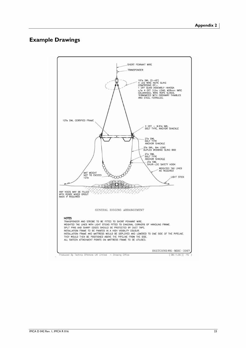
Appendix 2
Example Drawings

24 IMCA D 042 Rev. 1, IMCA R 016