· 13 diversion booming 35 ... the u.s. coast guard (uscg) ... all the techniques discussed may be...
TRANSCRIPT


-......
-
-
-
ALASKA POWER AUTHORITY
BEST MANAGEMENT PRACTICES MANUAL
OIL SPILL CONTINGENCY PLANNING
February 1985
Prepared by Frank Moolin &Associates, Inc.
under contract to Harza-Ebasco
Susitna Joint Venture
TK'14 ::lb",.s<lA~3
V\D 1:111 Ip

-PREFACE
This manual is one of a series of "best management practices" manuals to be usedin the design, construction, and maintenance of Alaska Power Authority projects.It represents a coordinated effort involving federal, state and local government
~ agencies, and special interest groups.i
The Alaska Power Authority intends that applicable guidelines and state-of-theal~t techniques contained in the manuals will be incorporated where appropriateinto the contractual documents for projects constructed, maintained, or operatedby or under the direction of the Alaska Power Authority.
--
-\i
-
-
Table
1
List of Tables
Potential Containment Sites in Waterbodies
Page
18
List of Figures
- Figure Page
1 Contingency Response Organization and Responsibilities 9- 2 Spill Notification and Coordination System 11
3 Water By-Pass Dam (Valved Pipe) 204 Water By-Pass Dam (Inclined Tube) 21
5 Underflow Weir 22
6 Diversion Berms 24
7 Overflow Berm 26
8 On-Land Berm 27
9 Culvert Blocking 29
10 Culvert Underflow Device 30
11 Interception Barriers 31
12 Containment Booms 33
13 Diversion Booming 35
14 The Slot 37-, 15 Frozen Barrier on River or Lake Ice 39
16 Sorbent Fence 40
I"""" 17 Skimming Contained Spills 48
18 Skimming Uncontained Spills 49
"'""!

-
---
-
CHAPTER 1 - INTRODUCTION
The Alaska Power Authority has prepared this best management practices (BMP)
manual as one of a series of manuals to be used in design~ construction, opera
tion, and maintenance of Power Authority projects in Alaska. This BMP manual
identifies the major elements that comprise an oi1* spill contingency planning
document and describes specific techniques for spill containment~ cleanup~
_disposal and reclamation.
The U.S. Environmental Protection Agency (EPA) has regulatory jurisdiction over
discharges into navigable waters of the United States and adjoining shorelines.
EPA requires a Spill Prevention, Containment, and Countermeasure Plan (SPCC) for
any above-ground petroleum storage greater than 660 gallons in a single tank or
1~320 gallons in more than one tank and for underground tanks greater than
42,000 gallons. The Alaska Department of Environmental Conservation (ADEC)
requires a spill contingency plan for any facility with a storage capacity of
420,000 gallons or greater of petroleum products. The U.S. Coast Guard (USCG)
requires an operations manual for facilities that transfer oil in bulk to or
from any vessel. Each of the three documents must contain specific information
as required by regulations and, for EPA and USCG documents, the information must
be presented in a prescribed format.
* For readability, this document uses the term "oil'· spill. It is recognized,
however, that other petroleum products, such as gasoline, will be used and
stored at project sites. The guidelines and techniques discussed in this manual
also apply to these other products.
-1-

"""'
l',
-,
The information presented in this manual, therefore, should be used only as a
guide in preparing contingency or operations plans for specific projects. Not
all the techniques discussed may be suitable for a particular project, some of
them may not be acceptable from an environmental standpoint for a specific
situation, and new techniques developed after publication of this manual may be
more effective than those mentioned herein. Moreover, not all of the el ements
required by state and federal regulations to be included in a contingency or
operations plan are discussed.
Fei" owing are the regul ati ons governing oil spill contingency and operations
plans:
Code of Federal Regulations (CFR)
40 CFR 110
40 CFR 112
33 CFR 153-156
Alaska Administrative Code (AAC)
18 AAC 75
-2-

CHAPTER 2 - POLICY GUIDELINES
"""
......
-
It is the pol icy of the Power Authori ty to requi re every reasonable action to
pr'event spills of petroleum products and if they do occur, to minimize environ
mental damage and assure the safety of project workers and the publ ic. The
Power Authority and its contractors will comply with relevant pollution laws for
the protection and conservation of environmental resources.
Pr'evention of spills associated with energy facilities is a prime objective of
the Power Authority. (Many of the techniques and practices related. to spill
prevention are contained in a companion BMP manual on fuels and hazardous
millterial s.) To assist in accompl ishing thi s objecti ve, the Power Authori ty and
- its contractors will:
Incorporate state-of-the-art spill prevention measures in the design
~ and construction of new facilities and improvements to existing
facilities.
-Inspect' facilities to determine potential sources of spills and
remedial measures.
Review construction, operation, and maintenance procedures with
respect to prevention of spills.
-3-

.....
.....
--
.....
.....
.....
Establ ish formal training sessions for project personnel to ensure
familiarity with facilities, equipment, procedures, and contingency
response plans.
In the event of a spill, the Power Authority and its contractors will take all
m€!asures necessary to minimize damage to the environment and to protect project
workers and the public. Priority will be given to safety considerations followed
by a commitment to prevent spills from reaching environmentally sensitive areas.
Project-specific contingency plans will be developed, as required by federal.and
state regulations, and will be ready for implementation before construction is
initiated. These plans will specify procedures to:
Ensure worker and public safety
Rapidly and accurately detect and locate spills
Minimize spill volume and spread
Clean up, rehabilitate and restore affected areas
Notify and cooperate with applicable regulatory agencies
-4-
-
.-
.....
-'"""'
.....
CHAPTER 3 - ELEMENTS OF A CONTINGENCY PLAN
This chapter discusses the major elements of contingency planning and operations
documents, as required by EPA, ADEC, and USCG regulations. Once again, the
rE!ader is cautioned that not all required el ements are incl uded and that the
rE!gul ations 1isted in Chapter 1 of this manual should be used in preparation of
plans for specific projects. Further, the techniques presented may not be
applicable to specific projects or sites or may be superceded by new technology
dE!Veloped since publ ication of this manual •
3,,1 PROJECT DESCRIPTION
Project contingency or operations plans should describe in detail those
components involved with the storage, transfer and transport of petroleum
products. Information should include:
Physical and chemical characteristics of the material
Location at facility
Design, materials, and engineering features
Volume
Containment and drainage systems
Inspection methods and procedures
Security and fire fighting systems
Leak detection and emergency shutdown systems
-5-
-
-.....
~r
3.. 2 SPIll ASSESSMENT
Project contingency or operations plans must include an assessment of most
likely discharges and the greatest possible discharge that could occur at
the facility. This information is not only required by government regula-
tion, but also is necessary in planning-containment methods and structures,
estimating response times, and determining cleanup equipment requirements.
Factors that contribute to an assessment of potential pischarges are:
Physical and chemical characteristics of the substance
Spill locations
Spill vol urnes
Amount of area covered by spill
Rate of release
Direction of movement
Description of contaminated area
Proximity to environmentally sensitive areas, and trail s, roads,
waterbodies
Equipment, storage tanks or containers, vehicles involved
Availability of personnel
Weather and seasonal conditions
3.3 TRAINING PROGRAM
Training and advance preparation are integral factors in a spill contingency
pl an to insure that personnel respond rapidly and effectivel y, util i ze
material and equipment in an efficient manner, follow the actions specified
-6-

.....
-
.....
in the plan, and are able to handle situations not foreseen in the plan.
Both classroom and field training sessions must be provided to insure that
all involved personnel will be prepared to react to a spill and that they
are educated in the hazardous tasks to be performed as well as with the use
of any personal safety equipment required for the spill response.
Classroom discussion sessions should include familiarization with all
aspects of the contingency plan, the legal and environmental implications
of spills, and the importance of successfully executing the plan in the
event of a spill. Personnel should be assigned specific tasks and be
provided with detailed instruction to insure that they are famil iar with
their task and associated spill control equipment, and how these tasks
relate to the overall plan.
Field training sessions should be held to familiarize personnel with
containment equipment and their deployment, use of sorbents, and recovery
equipment. Actual field deployment of containment and cleanup equipment at
a containment site should be included in these sessions. Full-scale drills
to include all response actions involved in an actual spill should be
conducted periodically.
3,.4 RESPONSE ORGANIZATION
Sequential actions and responsibil ities in the event of a spill should be
clearly defined to enable rapid and effective response. A project contin
gency or operations plan should specify immediate response action responsi
bilities to:
-7-
-
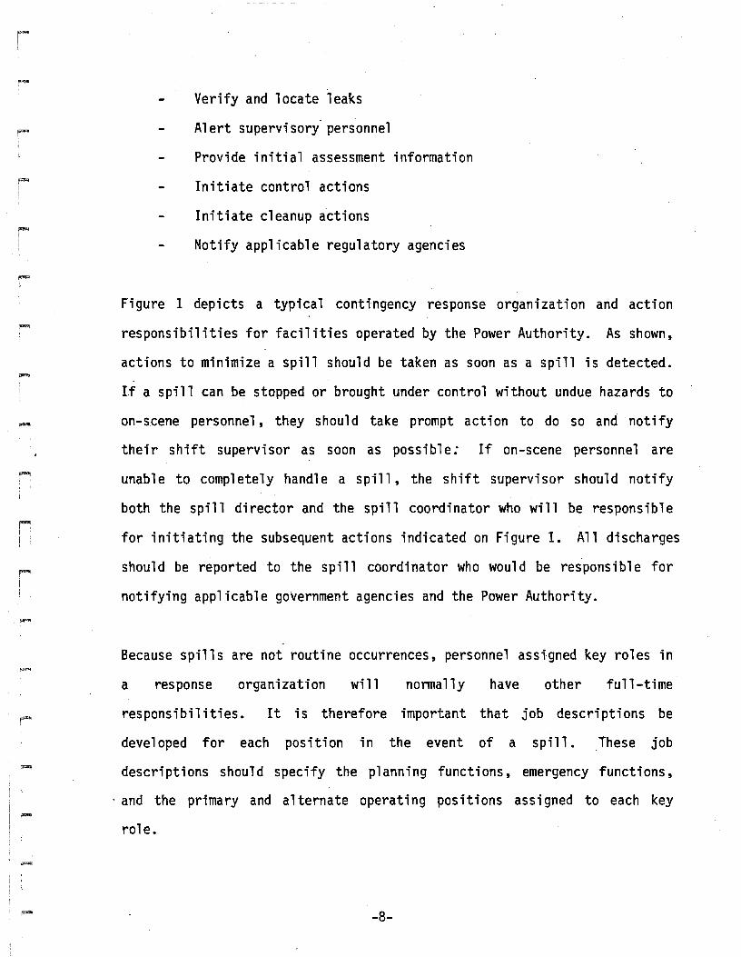
Verify and locate leaks
Alert supervisory' personnel
Provide initial assessment information
Initiate control actions
Initiate cleanup actions
Notify applicable regulatory agencies
Figure I depicts a typical contingency response organization and action
responsibilities for facilities operated by the Power Authority. As shown,
actions to minimize a spill should be taken as soon as a spill is detected.
If a spill can be stopped or brought under control without undue hazards to
on-scene personnel, they shoul d take prompt action to do so and notify
their shift supervisor as soon as possible: If on-scene personnel are
unable to completely handle a spill, the shift supervisor should notify
both the spill director and the spill coordinator who will be responsible
for initiating the subsequent actions indicated on Figure I. All discharges
should be reported to the spill coordinator who would be responsible for
notifying applicable government agencies and the Power Authority.
Because spills are not routine occurrences, personnel assigned key roles in
a response organization will normally have other full-time
responsibilities. It is therefore important that job descriptions be
developed for each position in the event of a spill. These job
descriptions should specify the planning functions, emergency functions,
. and the primary and alternate operating positions assigned to each key
role.
-8-

~...I
II
SPILL DETECTION. ...... ....... ....... ....... ....... ....... ....... .....------.... ,..._--:...._-.....,ON-SCENE
PERSONNEL
..... ..... ..... ..... ..... ..... ..... .....
-t
TAKE INITIAL IACTIONS
I
IL _
SHIFT
SUPERVISOR--
MONITORING
INSTRUMENTS
II____ J
NOTIFY I
ADEC USCG EPAI
,.....---1 SPILL DIRECTOR 11--------------1
....ACTIVATE L..
~----tRESPONSETEAMr----
ASSESS SPIU r
PERSONNELSAFETY
VERIFY SPILLSTOP/LIMIT FLOW
TYPE OFHAZARDOUS
MATERIA'L• VOLUME• MOVEMENT• THREATENED
AREAS
SPILL I APA PROJECT ICOORDINATOR ,1------11 MANAGER
.....---.11---, I IGOri~h;ISON ISUPPORT: ADVISORY: IpUBLlCRELATIONs!
LOGISTICS SAFETY
MANPOWER TRAINING
COMMUNICATION ENVIRONMENTAL
DOCUMENTATION ENGINEERING
....
DIRECTRESPONSE
ACTIONS:--...-oj.CONTAINMENT• EXCLUSION• CLEANUP• RESTORATIONS
ALASKA POWER AUTHORITY
CONTINGENCY RESPONSE
ORGANIZATION AND
RESPONSIBILITIES
FIGURE 1
.....
.-
--
.-
r
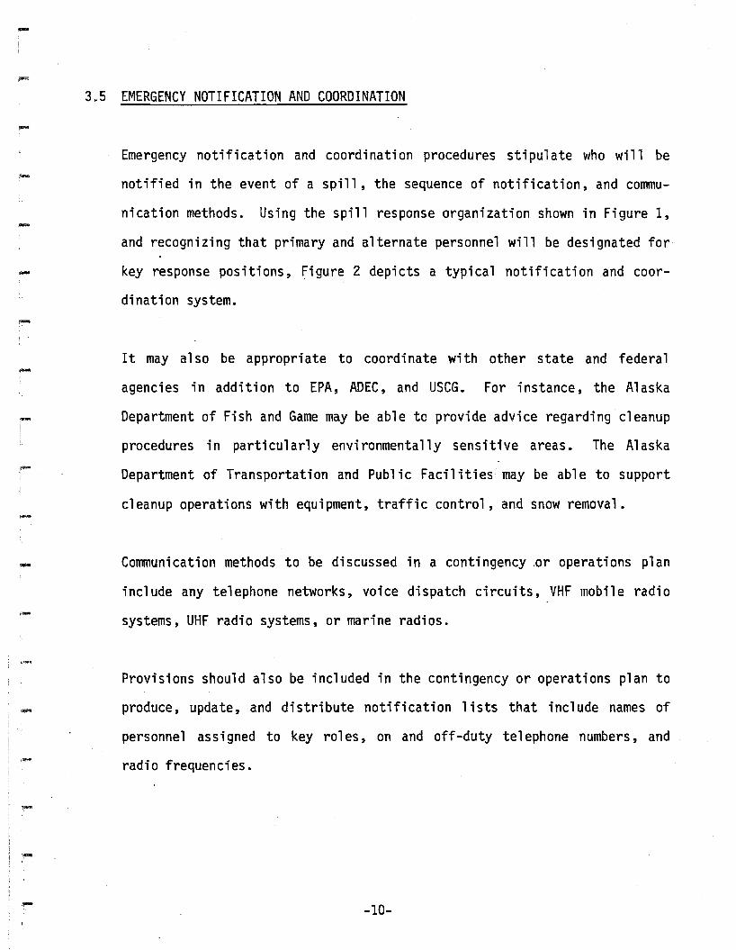
3.. 5 EMERGENCY NOTIFICATION AND COORDINATION
Emergency notification and coordination procedures stipulate who will be
notified in the event of a spill, the sequence of notification, and commu
nication methods. Using the spill response organization shown in Figure 1,
and recognizing that primary and alternate personnel will be designated for
key response positions, figure 2 depicts a typical notification and coor
dination system.
It may also be appropriate to coordinate with other state and federal
agencies in addition to EPA, ADEC, and USCG. For instance, the Alaska
Department of Fish and Game may be able to provide advice regarding cleanup
procedures in parti cul arly envi ronmentally sensitive areas. The Al aska
Department of Transportation and Public Facilities may be able to support
cleanup operations with equipment, traffic control, and snow removal.
Cormnunication methods to be discussed in a contingency or operations plan
include any telephone networks, voice dispatch circuits, VHF mobile radio
systems, UHF radio systems, or marine radios.
Provisions should also be included in the contingency or operations plan to
produce, update, and distribute notification lists that include names of
personnel assi gned to key rol es, on and off-duty telephone numbers, and
radio frequencies.
-10-

,~
.....
.....
SHIFT SUPERVISORS""",.,
,. '",. '",. '",. '",. '",. '",. '"~
SPILL DIRECTOR SPILL COORDINATOR
LEGALGOV'T. LIAISON H APA r-RESPONSE PUBLIC PROJECT
~TEAM RELATIONS MANAGER
ENVIRONMENTALON-SITE GOV'T. AND ENGINEERING~--- REPRESENTATIVES ADVISORS
ADEC
EPA ~
USCG
-
-
.....
-
.....
ALASKA POWER AUTHORITY
SPILL NOTIFICATION AND
COORDINATION SYSTEM
FIGURE 2

.....
-
ro-I
,....
3.6 REPORTING PROCEDURES
Reporting procedures should be established in the contingency or operations
plan to ensure documentation of discharges as required by EPA, ADEC, or
USCG regulations. Documentation will also provide a means of measuring the
success of the containment, excl us i on and cl eanup operati ons and thus
suggest modifications or improvements to the plan. The following example
of reporting procedures is based on the response organization depicted in
Figure 1.
Documentation would commence when spills are reported to the shift supervi
sor. The shift supervisor would complete a written report to include the
name and address of the person reporting the spill, approximate location of
the spill, approximate quantity of spill, and type of substance. This
report would be submitted to the spill coordinator who would be responsible
for compiling all documentation of the incident from spill occurrence
through cleanup actions to final post-spill assessment. Among the types of
information required to provide documentation are:
Cause of spill (equipment failure, persons causing spill, viola
tion of safety or operational practices, vandalism)
Spill characteristics (spill volume and direction of movement,
type of substance, rate of rel ease, proximity to waterbodi es,
effectiveness of containment)
Photographs (identified per location, date, time, subject,
direction)
Weather conditions
-12-

-
-
-
Equipment performance records
Cost incurred
Record of contacts with regulatory agencies
Reports to government agencies
Information gathered for the documentation effort would be used to prepare
the following formal reports required by the regulatory agencies:
Oil discharges on land of less than 10 gallons.
Spill coordinator will submit a completed report to ADEC within 7 days
after the reported spill. Copy to Power Authority project manager.
Oil discharges on land of 10 gallons or greater, any oil discharges on
water, and all other hazardous substances discharges of any quantity
on land or water.
Spill coordinator will immediately notify ADEC, EPA and/or USCG by
telephone (or other designated emergency contact system) followed by
written notification as soon.as possible. Spill coordinator will make
a formal report to ADEC and EPA, and to the USCG (tidewater spills
only) within 15 days of the discharge or completion of cleanup, after
revi ew by Power Authority 1ega1 advi sors. Copy to Power Authori ty
project manager.
The following information is required in reports to government agencies:
-13-

-
-
.....
--
Date and time spill occurred or was observed
Location of spill·
. Person responsible for discharge
Estimate of amount spilled and type of substance
Cause of discharge
Environmental damage
Cleanup actions undertaken
Location and method of ultimate disposal of ·the substance and
contaminated cleanup material, including date of disposal
Action being taken to prevent recurrence of the discharge
3.7 SAFETY GUIDELINES
,Human safety should always have first priority in a spill situation. This
safety interest extends to public exposure as well as to the safety of
project personnel. The following guidelines should· be considered in
formulating safety practices and procedures for spill activities.
Prior to starting the job, personnel should be informed on-site
of the potential hazards and trained in the use of spill cleanup
equipment, safety measures, and fire suppression practices.
Procedures should be developed for safety review and enforcement
of practices.
Potentially hazardous areas and conditions should be defined and
-14-

....
restrictions placed upon personnel and operations to be allowed.
Personnel should be specifically designated to provide safety and
security actions with instructions to restrict unrequired people
from access.
Equipment to be employed will be checked to prohibit ignition of
the residue product.
No smoking areas should be designated.
In addition to human safety, potential hazards and wildlife
concerns should be noted and preventative safety measures
initiated.
Repair operations, particularly the use of cutting torches and
welding equipment must be recognized as having an ignition
potential.
Equipment should be cleaned prior to storage.
Measurements should be made to test for explosive conditions and
hydrocarbon vapor concentrations whenever possible.
Nightt"ime operations must be approached with extra care. The use
of field lighting introduces a possible ignition hazard.
-15-
-
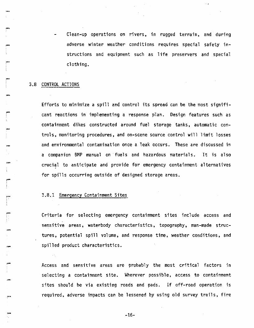
Clean-up operations on rivers, in rugged terrain, and· during
adverse winter weather conditions requires special safety in
structions and equipment such as 1ife preservers and special
clothing.
3.8 CONTROL ACTIONS
Efforts to minimize a spill and control its spread can be the most signifi
cant reactions in implementing a response plan. Design features such as
containment dikes constructed around fuel storage tanks, automatic con
trols, monitoring procedures, and on-scene source control will limit losses
and environmental contaminatlon once a leak occurs. These are discussed in
a companion BMP manual on ·fuels and hazardous materials. It is also
cruci~l to anticipate and provide for emergency containment alternatives
for spills occurring outside of designed storage areas.
3.8.1 Emergency Containment Sites
Criteria for selecting emergency containment sites include access and
sensitive areas, waterbody characteristics, topography, man-made struc
tures , potential spill vol ume ,and response time, weather conditions, and
spilled product characteristics.
Access and sensitive areas are probably the most critical factors in
selecting a containment site. Wherever possible, access to containment
sites should be via existing roads and pads. If off-road operation is
required, adverse impacts can be lessened by using old survey trails, fire
-16-

-
-~
I
I.
breaks and seismic trails. Particularly sensitive areas are those where
removal of organic 1ayers, ground covers, and shrubs expose the soil.
Areas that should be avoided during summer activities are wetlands, slopes
in excess of 10 percent, and riparian and alpine tundra communities.
During winter, areas to avoid are slopes in excess of 10 percent and alpine
tundra communities.
Site selection within waterbodies must consider seasonal characteristi~s as
well as access, working space requirements, and environmental constraints.
Potential containment sites during seasonal periods are shown on Table 1.
Natural terrain features, such as depressions or old moraine ridges, may be
suitable for containment sites. Man-made barriers, such as work· pads,
roads, culverts, bridges, spur dikes, and low water crossings could provide
excellent sites. Additional possibilities include old survey and seismic
trails, fire breaks, material sites, and other cleared areas.
The potential volume of a spill is an obvious factor in selecting contain
ment sites large enough to cope with containment, cleanup and disposal
activities. Response times to reach a containment site, especially given
any weather or transportation delays should also be considered.
3.8.2 Containment Methods and Implementation Guidelines
The following discussion describes various methods to limit the spread of a
spill and guidel ines for selecting appropriate techniques at potenti al
spill locations.
-17-

TABLE 1
POTENTIAL CONTAINMENT SITES IN WATERBODIES
-
Se~ason
Summer
Low Flow Period
High Flow Period
Fr'eezeup
Before Ice Cover
JI,fter Ice Cover
Winter
Flow Beneath Ice
Flow at Open Leads
Intragravel Flow
BreakUl.E.
Before Ice Movement
During/After IceMovement
Potential Site
Man-made structures1, natural pools, backwaterareas, gravel and sand bars.
Man-made structures, side channels, backwaterareas, vegetated banks
Man-made structures, natural pools, ice jams,gravel and sand bars
Man-made structures, side channels, bacKwaterareas
Man-made structures, side channels, backwaterareas, upstream end of aufeis areas
Upstream entry
Trenches in streambed, man-made structures,upstream end of aufeis areas
Man-made structures, backwater areas, sidechannels
Man-made structures, backwater areas, sidechannels, vegetated backs
1 Man-made structures include bridges, culverts, spur dikes, low watercrossings.
-18-

--
-
-
..-
-
"
3.8.2.1 Techniques
QAMS - There are two types of dam construction appropriate for containing
spills of petroleum products: complete blocking of an actual or potential
drainage course (a blocking dam), and blocking of oil flow while letting
water continue downslope (an underflow dam) or downstream (an underflow
weir) .
Blocking Dams - Blocking dams should be constructed only across
drainage courses which have little or no water flow. The dam should
be situated at an accessible point where there are high banks on the
upstream side. It must be well keyed into the banks and buttressed to
support the oi 1 and water pressure. It can be constructed from
several types of materials - earth, snow, sandbags, sheets of metal or
wood, or any material that blocks flow.
The dam can be built across the drainage course to form a holding pond
or reservoir to contain the oil and water. Water trapped behind the
dam can be pumped out by placing the suction (intake) hose at the base
of the dam on the upstream side, leaving oil trapped behind the darn
for subsequent removal. The discharge (outlet) hose should be placed
on the downstream side. Trapped water can al so be moved across the
dam with one or more siphons •
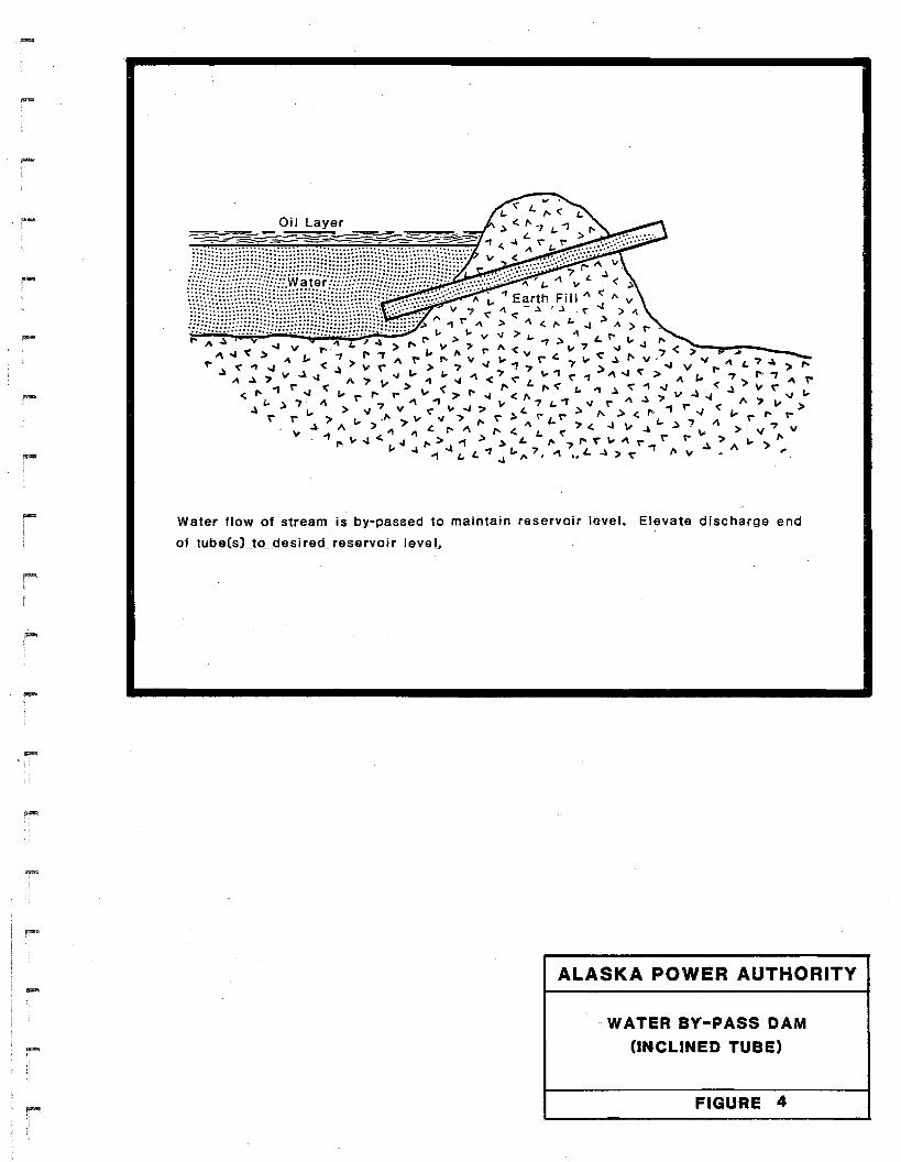
Underflow ·Dams and Weirs - For waterways with higher stream flow
rates, an underflow dam or weir can be used (Figures 3, 4, and 5 ).
, If these techniques are to be effective, the surface of the oil must
-19-

......
-
.,VALVED PIPE(S) OFADEQUATE CAPACITYTO BY-PASS WATER..
,~_ater flow of stream_Qcsurface water drainage is by-passed to maintain reservoirv
ls.!tJH. Oil is skimmed off or absorbed as conditions dictate.
Crest of dam should be of sufficient width to accommodate compaction vehicle.
Height of fill is 2 to 3 feet above fluid level. Normal fall angle of fit I will suffice
lor sloping.
ALASKA POWER AUTHORITY
WATER BY-PASS DAM
(VALVED PIPE)
FIGURE 3
,....
Water flow Of stream is by-passed to maintain reservoir level. Elevate discharge end
of tube(sLto_desired_ reservoir level.
ALASKA POWER AUTHORITY
WATER BY-PASS DAM
(INCLINED TUBE)
FIGURE 4

-
-rIII
,...i
rII
Wood or Sheet Meta'
ALASKA POWER AUTHORITY
UNDERFLOW WEIR

-.....
.....
.....
.....
-
always be below the lip of the dam or weir, and the oil/water inter
face must be above the top of the underflow opening •
The underflow dam can be constructed by placing pipes of appropriate
size on the streambed and building an earthen or sandbag dam over the
pipe across the waterway. The diameter of the pipe will depend on the
flow rate of the stream and the depth of the water behind the dam.
For I example, 24- to 30-inch diameter pipe will have sufficient
capacity for a flow rate of up to 30 cubic feet per second. If time
does not allow for pipe diameter calculations, a diameter larger than
required will control flow if it is inclined at the proper angle or if
a valve is used. A pair or series of dams may be required downstream
if sufficient underflow cannot be maintained.
An underflow weir can be simple yet effective technique in small
streams. A piece of wood or sheet metal placed across the stream and
firmly anchored to the banks will stop the oil flow while allowing
water to continue downstream.
~ERMS - Berms are constructed to control flow by diversion or overflow.
For creeks and ri vers, overflow berms (wei rs) or di vers ion berms can be
constructed from materials in the floodplains; for terrestrial spills,
earth berms can be built to divert or impede flow. In fast-moving streams,
berms may have to be continually maintained.
Diversion Berms - Diversion berms would be constructed from floodplain
materials on large rivers (Figure 6). In most situations, they should
-23-

RIVER FLOW
COllection Point
This represents a series of diversion berms joined by booms. They are positioned
so that a spill can be diverted to a location with adeQuate storage and ar.cessability
to removal eQuipment. If stream and spill conditions permit, one berm may be all
that is reQuired.
ALASKA POWER AUTHORITY
DIVERSION BERMS
FIGURE 6

be constructed ina seri es, connected with short pi eces of boom in a
pattern that forces oil to flow into a containment pit, side channel,
or similar feature ·for temporary storage. The spacing between each
berm should allow water to flow under the connecting booms while
forcing oil to the side. The size and angle of the berms will be
dictated by stream velocity, channel size, and oil spill volume. As
these factors increase, the required size of the berms will increase,
and the angle between the upstream side of the berms and the stream
bank will decrease.
Overflow Berms (weirs) - The purpose of overflow berms or weirs is to
reduce water velocity by widening and deepening the stream. They can
be constructed in smaller streams or in the side channels of larger
rivers (Figure 7). Overflow berms must be constructed across the
entire channel. Materials should be excavated from the upstream side
of the berm, creating a pool where stream flow wi 11 be retarded,
permitting boom deployment and oil removal upstream from the berm.
The required height and width of the berm will increase with stream
depth and water velocity.
Berms Built on Land - Land berms act as barriers to spill flow and may
also be used to divert the flow to protect a sensitive area. Windrows
along a road can prevent a spill from crossing the road or divert it
into a storage area (Figure 8).
CULVERT BLOCKING - The most effective way to block culverts is to pile
-25-

Boom --.,,'::~
TOP VIEW
Overflow Berm
!' -J <.., .::;::;:::::::::::::::::::::::.:::••.••>!' -J, ~ A V r- 1\ " ~ A I'" 7~ ••••: ••••••• :...... .. <oJ' "" v < > " L.
""I" ".)"IV"vl'"vV"IV I'>r ...Jt.
.) '"' L'" .., 1'"7 ~ l. I. r-..J « 1'"" < >" "" > r- I. o.J < ,..1'"< 1\~_7._V ~ "~V..,j>I.,..,..
... ..,j '"
«" "r- <. .SIDE VIEW
Oil Layer Oil Skimmer
ALASKA POWER AUTHORITY
OVERFLOW BERM
FIGURE 7

-
....
-
ALASKA POWER AUTHORITY
ON-LAND BERM
FIGURE 8

-
,-
-
dirt, sand, or other earthen materials over the end of the culvert (Figure
9). A pump or siphon may be required to remove impounded water from the
blocked culvert. Small volumes of water can be passed through a pipe
covered with sandbags or dirt. Large culverts such as those that transport
entire streams can be blocked with an underflow device (Figure 10). It may
also be possible to install an inverted elbow on a culvert intake which
will pass water below the oil 1ayer.
INTERCEPTION BARRIERS - Interception barriers, such as trenches and sheet
barriers (Figure 11), are used to intercept subsurface flow of spilled oil
through a permeable layer that mayor may not be transporting groundwater
or between the vegetative mat and the ground surface. The actual direction
of subsurface flow must be determined before a barrier is installed as the
subsurface geology may permit oil to flow in directions that do not coincide
~~th surface gradients.
lRENCHES - While a trench can be an effective technique for containing the
flow of oil through a subsurface layer, excavating a trench in permanently
frozen soils may cause more damage than the migration of the oil. The
trench should be excavated at right angles to subsurface flow, extend about
18 inches below the 0 ill eve1, and be wi de enough to accommodate the
a.nticipated method of removing the oily water. The downstream side and
bottom of the trench should be covered with visqueen or a similar imper
meable material.
SHEET BARRIERS - Sheet barriers constructed of metal or plywood driven into
the ground can be used where the flow is near the surface. The overlapped
-28-

",...
..r-
r
.---~
The blocking devices should be covered with earthen materials.
SAND BAGS
PLYWOOD SHEET
ALASKA POWER AUTHORITY
CULVERT BLOCKING
FIGURE 9

"""I
-
"""I,
-
r
ALASKA POWER AUTHORITY
CULVERT UNDERFLOW DEVICE
FIGURE 10

TRENCH
..!
,....
VISQUEEN(OR SIMILAR MATERIAL)
..... I. , •
jMETAL SHEETS·
Pooling
'" ...~ >,.. '"
ALASKA POWER AUTHORITY
INTERCEPTION BARRIERS
1---------------------1FIGURE 11

.....
'"""
-.
sheets should extend down to about 18 inches below the oil level, and up
from the 9round surface to create a ponding area for the oil. Sheet
barri ers shaul d be i nsta11 ed. at ri ght angl es to the subsurface flow and may
bend upslope at the ends.
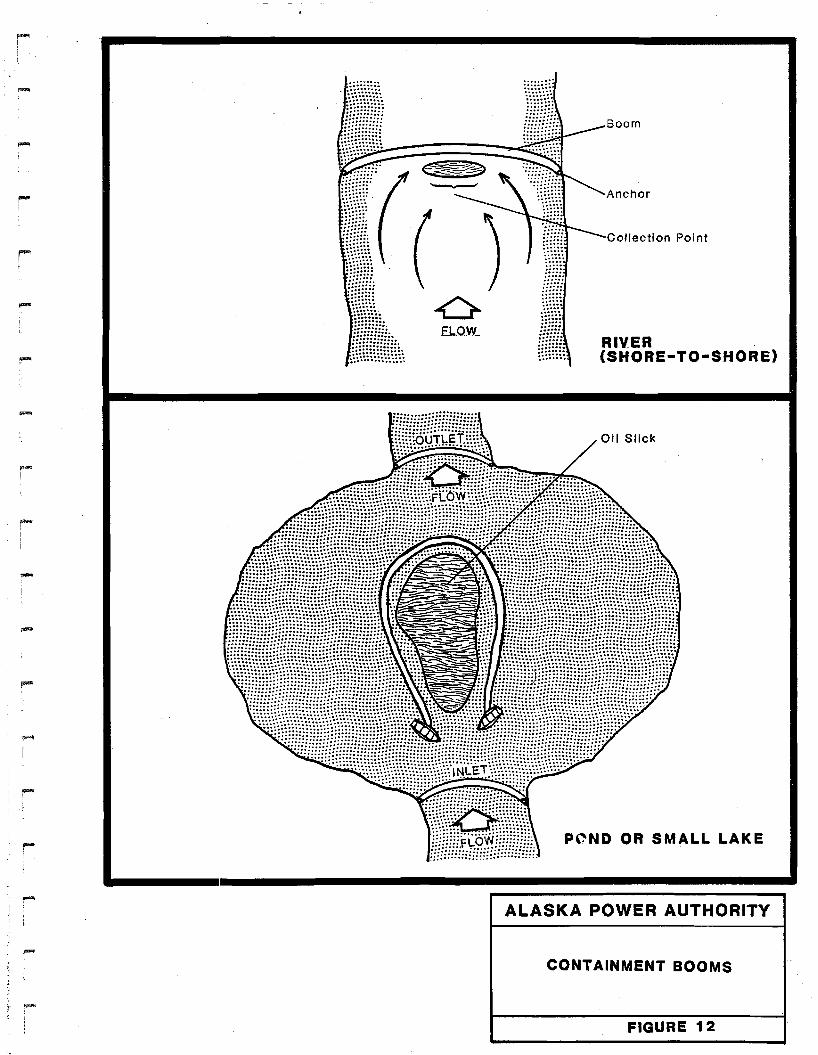
BOOMS - Booms are used to contain oil spills on water by either blocking
the flow olr diverting it to a collection point. Many different types of
booms are commercially available or can be fabricated on site. All booms
have a means of flotation, a barrier extending below (a skirt) and above
the water surface, and a means of achieving longitudinal strength.
Containment Booms - Booms to contain the flow of oil are generally
deployed from bank to bank or from shore to shore (Figure 12).
Booms deployed across the inlet stream to a lake may prevent oil from
reaching the lake itself. Booming the outlet of a lake will create a
large storage area where the decrease in current velocity will facili
tate E!asier cleanup. Once it has reached a lake, two boats towing a
long boom can encircle the slick and prevent it from spreading .
. Booms deployed across a river or stream will usually contain the flow
of on if current velocity is less than about 1 knot (1.7 feet per
second). Wind wil,. affect surface water velocity by a factor of
approximately 3 percent of the wind speed. This should be taken into
consideration when wind is blowing downstream, upstream, or across a
lake. If this technique is used, the oil will have to be removed
rapidly from the upstream side of the boom. Containment booming is
-32-
( ).0
El..ow..
....
....
....
~ ...............
"~\{)((,.:::::" :::::::::;;:::==:~
. .:::::::::.......................
~\\{{{{{{{{{{\h
Boom
Anchor
Collection Point
RIVER(SHORE-TO-SHORE)
POND OR SMALL LAKE
ALASKA POWER AUTHORITY
CONTAINMENT BOOMS
FIGURE 12

.....I
-
-
not likely to be useful on large rivers or whenever current velocities
are over 1 knot; diversion booming will be necessary.
Where oil is flowing into a lake or stream over the bank or leaking
from the ground into a water body, booms placed parallel to the bank
can cl~eate a quiet surface area from which the oil may be skimmed.
Booms can al~o be placed parallel to shorelines and banks to exclude
oil from sensitive areas.
Diversion Booms - Diversion booms (Figure 13) are deployed to direct
oil towards a containment pit/collection area, or to divert oil away
from E!nvironmentally sensitive areas. Depending on river characteris
tics cLnd size, diversion booms can be deployed as single or connected
sections of booms, multiple booms staggered across main or side
channE!ls, or in conjunction with berms or ri ver bars. When using
diversion booms to divert oil towards a containment pit/collection
area, the downstream end at the collection area is anchored by natural
features, steel pipes, or tracked vehicles. The upstream end is fixed
to a berm, boat, or tracked vehicle,. Diversion booms deployed to
protect environmentally sensitive areas will usually be fixed between
boats ~I natural features, or berms.
COLLECTION AREAS AND DIVERSION PITS - Oil spills reaching moving bodies of
water can be contained by diverting the spill with berms and booms to a
collection area or containment pit adjacent to the affected water system.
In incised river systems, oil may have to be diverted to high water
channels, oxbow lakes, or areas of relatively quiet water. In braided
-34-

Anchor ----,IiI::l......Collection Point--.....
........,,~ ---1F---Anchor"" ......... ...............................~ .....
0 ",' .....I \ ....." .....
\ ~--Anchor
II
.-
,....
I"""!
oFLOW
ColLection Point----.,....:
DIVERSION - RIV ER(SUMMER)
oWIND
DIVERSION - LAKE(SUMMER)
ALASKA POWER AUTHORITY
DIVERSION BOOMING
FIGURE 13
-
!'"""I
I
......
--
rI
river systems, existing or abandoned material sites should be used wherever
feasible. If conditions allow, containment pits should be excavated in the
floodplain at approximately the same angle as the berms and booms have been
constructed and deployed in the river channel. Containment pits excavated
in floodplain materials will have to be made impermeable either by excavat
ing the pit below the groundwater table or by covering the walls of the pit
with plastic sheeting, clays, or similar materials. If the water level of
the pit be!comes too high, excess water can be discharged via underflow
siphons or pumps. Also, if the water level cannot be maintained, additional
water can be added to the pit with pumps or by adjusting the booms divert
ing oil into the pit, or the pit can be deepened moving the bottom closer
to the water table.
CONTAINING OIL UNDER ICE - Two methods, a slot and a frozen barrier, can be
used to divert oil from water flowing under ice to a location where it can
be contained and cleaned up.
The S"lot - This method requires a high velocity current and invol ves
cutting a slot in river ice that will allow oil to flow "out and over"
the surface of the ice (Figure 14). The slot should be rectangular
and span the width of the highest current velocity. The longitudinal
walls of the slot should be cut at right angles to the current and
slope towards the center with the downstream wall dipping at least 45
degre.~s upstream. It is essential that any void between the surface
of the stream and the bottom of the ice be minimal or that actual
flowing water-ice contact is made. If possible, the slot should be
cut above a natural highpoint in the streambed so that water flowing
-36-

-
.....
....
RIYER BANK
ALASKA POWER AUTHORITY
THE SLOT
FIGURE 14

-
---
over the highpoint will force the floating oil trout and over" the ice.
Alternatively, an artificial highpoint can be constructed by dropping
heavy sandbags through the slot along the downstream wall so they come
in contact with the flowing water.
Frozen Barrier - A conventional boom, plywood or steel sheeting, or
wooden planks can be frozen in place on a lake or a river to divert
oil to a collection point (Figure 15). A slot wide enough to accommo
date the barrier is cut in the ice. The barrier is then placed in the
slot so that it protrudes into the water for about 6 inches, and is
allowed to freeze in place. Ice is removed along the shoreline to
create! an area to store and remove the diverted oil.
SORBENTS - A sorbent is any material which absorbs oil or to which oil
adheres. While sorbents can be used as a protective barrier during
containment activities to keep oil from uncontaminated areas, they shoul d
never be used on water unless there is a definite way to recover them. On
small streams, fences constructed with stakes, wire mesh and sorbent
material can be used effectively (Fi gure 16). The mesh wi 11 hol d the
sorbent material while allowing passage of water. The sorbents must be
removed and replaced as they become saturated with oil.
3.8.2.2 Implementation Guidelines
Pads and Roads - Elevated pads and roads can serve as containment barriers
for spill s occurring upslope if drainage structures passing beneath them
are blocked. Dams should be constructed across the ditches on the upslope
-38-

-
--
I
rI
-.
SHORE OR .RIVER BEND
ALASKA POWER AUTHORITY
FROZEN BARRIER ON RIVER
OR LAKE ICE
FIGURE 15

r
--.....
-
-ALASKA POWER AUTHORITY
SORBENT FENCE
FIGURE 16

-
-
-
side of the elevated pads or roads to provide containment. Spills occur
ring on pads or roads can be confined with berms or darns. Construction of
a darn across a pad or road is especially important where it slopes toward a
river, creek or low-water crossing.
Tundra and Forest - Natural features such as tussocks, deadfalls, vegeta
tion, and snow will retard or stop surfaGe flow of oil and retain it.
Visqueen and/or sorbent materials should be placed on the uphill side of
naturally occurring barriers except snow.
Interception trenches can be excavated in non-permafrost areas to divert or
contain oil. Barriers can be placed in the vegetative mat to limitsubsur
face oil migration.
Small drainage courses and rivulets of meltwater can be blocked, using
sandbags, earth, snow, sheets of plywood or metal, sorbents, or materials
found on-sHe such as brush and logs. Drainage withfl owing water will
have to be dammed, either conventionally or with an underflow device. Oil
flowing down a dry drainage course can be partially contained by placing a
sorbent boom directly in the drainage course and/or by damming.
Small Creeks, Ponds, and Bogs - Containment of spills on small creeks
generally requires an underflow dam, an overflow berm, or a dam in conjunc
tion with a pump or siphon. These barriers should be located so that a
pond will form upstream from the barrier. Containment can al so be achieved
in pools behind log debris or jams. On fast-flowing creeks, a series of
containment barriers such as chicken wire (with sorbents) structures should
-41-

....
,
be used. During periods of high flow, it may be necessary to install steel
nets, chicken wire, or similar devices upstream of containment devices and
areas in order to protect both equipment and personnel from floating debris.
Outlets of ponds should be boomed to collect the oil on the surface of the
pond; additional booms should be deployed around the slick and around
sensitive Cilreas. Sorbent booms and conventional booms can be deployed in
tandem across the pond outl et. The sorbent booms shou1 d be farther down
stream where they will collect portions of the spill that may have passed
beneath or around the conventional boom.
Containment in bogs will most likely be limited to interception with
barriers and sorbent materials.
Large Rivers and Floodplains - Oil approaching the floodplain should be
contained Iwithin the drainage. course by constructing berms between the
spill and the main river channel. Diversion berms can be built to direct
the spill to a side channel, abandoned meander or channel, oxbow or oxbow
lake or excavated diversion pit. Log jams on sand or gravel bars and side
'channels create pools where oil can be contained; berms should be con
structed downstream from the debris to act as a backup containment barrier.
In some CCilses, aufeis can assist in bloclking subsurface oil flow along
river channels and force it to the surface where sorbents, sorbent booms,
and manual methods could be used to contain the oil. If oil becomes
trapped between layers of aufeis, especially when aufeis is fonned by an
aquifer discharging into a river from the bank, discoloration should be
-42-

,~
---
-
-
-
detectable and sorbents and barriers could be employed.
Intragravel flow may exist beneath the ice t even if flowing water is not
detected t and could provide a route for oil. The streambed would have to
be trenched deep enough to intercept the intragrave1 flow of oil t so it can
then be ponded.
Spills on the main river channel will be difficult to contain t and can be
treated several ways. During periods of high stream flow and ve10citYt a
series of diversion berms and booms should be used to divert the spill to a
containment pit or floodplain feature. Dig9ing a pit across the main river
channel will create eddies and pools of quieter water. This is practical
only on smaller rivers where equipment can be used. This technique is more
effective If/hen used with an overflow dam directly downstream. The pit
should be 'located where rapid removal of the oil is possible. While the
usefulness of booms on fast-flowing large rivers is limited, they can be
deployed in containment pits t upstream from natural or created pool s, and
near sandbars. Oil should be removed from behind the boom as rapidly as
possible to prevent loss of oil and to keep the strain on the boom to a
minimum. J~ spill entering the river can be partially controlled by deploy
ing booms parallel to the riverbank downstream from the point of entry.
Under some circumstances t side channel s can be converted to containment
ponds if the following procedures are used: 1) berm or dike the downstream
end of the side channel; 2) blast or construct a suitable channel for a
diversion skimmer in conjunction with an overflow berm so that the flowing
oil is diverted into the mouth of the side channel t but the majority of
water is a'llowed to flow down the main channel. Under most circumstances t
-43-

-
....
containment barriers will have to be continually maintained. Their resis
tance to er'osive forces can be increased if the upstream portion of earth
barriers is covered with rip-rap.
Spill travel beneath ice can be diverted by inserting sheets of plywood or
metal into slots cut in the ice and allowing them to freeze in place. When
ice is to thin to support heavy equipment and there are leads of open
water, sumner containment and diversion techniques with ice diversion
barriers can be used. Breakup poses the greatest hazard for personnel and
least chance for containment. On some small rivers or channels of larger
rivers, it might be possible to install steel nets upstream of a boom to
protect it and personnel from debris and ice. While temporary ponding of
water will exist behind log, debris, and ice jams, these jams may release
at unpredictable times .
Large Lake~~ - Booms are the most useful means of containment on large
lakes. The most effective technique is to encircle the spill with booms.
If oil is flowing into the lake, a boom should be secured to the shore on
one side of the point of entry and deployed around the periphery of the
slick by boat until the spill is encircled. As in containing oil on small
lakes, sorbent booms and conventional booms deployed in tandem may be
effective. Both should be deployed across the lake outlet with the sorbent
boom downstream. Sorbent pads can be distributed between the two booms.
This technique will pick up some of the o"il that passes the conventional
boom.
-44-
-~I
3.9 CLEANUP ACTIONS
This section discusses the basic techniques to clean up a spill and guide
lines for implementing appropriate techniques at potential spill locations.
In most instances t cleanup and removal of petroleum products should be
initiated immediately following implementation of containment measures as
changing weather conditions or containmen~ equipment failures may expand a
controlled spill unless the free substance can be removed. In some cases t
however t the cleanup of spill residue may cause more environmental damage
than either' natural dissipation or some form of treatment in place. The
spill director will determine the most appropriate cleanup alternative in
these instances.
3.9.1 Techniques
The basic techniques used singly or in combination to clean up a spill
include the use of heavy equipment t pressurized equipment t manual methods t
skimmers t pumpst burning t sorbents t and pumping and flotation. To supple
ment these techniques t which are discussed below t provisions should be made
for storing the recovered substance and contaminated materials before
transporting them to disposal areas. Typical storage equipment would
include 55-·gallon drums t pillow tanks t and fuel trucks.
Heavy Eguipment - Motori zed graders and paddl e-wheel scrapers can be used
in combination to remove continuous contaminated sands from river deltas
and floodplains. The graders cut and remove the contaminated layer and put
-45-
iI
....
-
....
it into windrows for pickup and transport to the disposal area by the
paddle-wheel scrapers. While scrapers alone can remove and haul the
material, they cannot control their depth of cut as well as graders and
operate 1ess effi c i entl y than the motor grader-scraper combi nati on. For
spotty contamination of sands, front-end loaders and dump trucks would be
the most efficient clean-up combination.
Bulldozers and front-end loaders can be used to remove contaminated gravels
from floodplains and for cleaning, up spills along roads. The bulldozers
excavate the contaminated gravels, which are picked up by front-end loaders
and loaded into dump trucks.
Backhoes, draglines, back-fillers, or grade-alls can be used in areas that
are inaccessible to large pieces of equipment, but adjacent to a floodplain~
road, or pad. Operating from these access points, the equipment can scoop
out the contaminated material and place it into a dump truck .
Motorized graders, loaders, and dump trucks can be used to clean up conta-
minated snow and ice along a pad or road, or on lake or river ice thick
enough to support heavy equipment. The technique is the same as used for
contaminated sand: windrow the material, pick it up, and transport it.
ContaminatE!d snow overlaying vegetated are!as should be removed with low
ground pressure loaders to avoid damaging the vegetative mat or insulative
1ayer underlying the snow. In areas adjacent to a roadway or graded
surface, a dragline or a back-filler could be used .
Pressurized Eguipment - Hydroblasting, air blasting, sand blasting, and
-46-

-,.,...
....
-
.....
steam cleaning can be used with prior approval from state and federal
agencies to remove oil from man-made structures and rocks. Care should be
taken to ensure that the cleaning techniques do not do more harm to the
surface than leaving the oil in place. Sorbents should always be used when
hydrob1asting and steam cleaning as these techniques will create pools of
oil below the surface being cleaned.
Manual Methods - Areas that are inaccessible to equipment, or with only
small amounts of surface to be cleaned should be cleaned by hand with hand
scrapers, wire brushes, shovels, rakes and sorbents.
Removal of contaminated vegetation or snow overlying vegetative cover might
a1so requ i r'e manual methods.
Skimmers - Skimmers are normally used in conjunction with booms or ice
diversion barriers to remove oil from the surface of the water and deposit
it in a sump tank. (Explosion-proof skimmers are required for gasol ine
spills.) A spill which is fully contained by booms is best removed by a
skimmer placed downwind from the highest concentration of oil (Figure 17)
within the boomed area. If the slick is too wide for the boom, skimming
shou1 d beg'in on the downwi nd side of the s1 i ck, move along the s1i ck, and
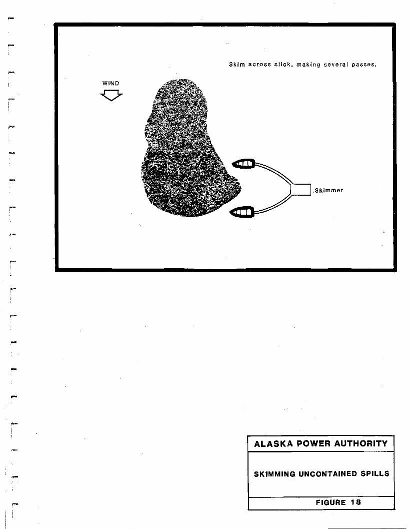
stay on thE! downwind side with each pass (Figure 18). The velocity of the
boats and skimmer should not exceed 1 knot (1.7 feet per second) .
Weir-type skimmers, which operate on the principle of gravity, work best in
calm waters with thick oil slicks. The top of the weir is positioned as
close as possible to the oil/water interface and the skimmer moves through
-47-

I
-
F"I
WIND
~O
Skimmer
ALASKA POWER AUTHORITY
SKIMMING CONTAINED SPILLS
FIGURE 17
....
Skim acr.oss slick, making several passes.
-
rI
;
r,.....I
WIND
.Skimmer
- ALASKA POWER AUTHORITY
SKIMMING UNCONTAINED SPILLS
FIGURE 18
.....
the slick or is positioned in the current to intercept the oil. Oil and
water flow across the weir into a sump 0'" enclosed area. With careful
adjustment of the weir, the maximum amount of oil and minimum amount of
water can be skimmed.
Rotating disc or endless belt skimmers remove oil from the water surface by
material oleophi'lic properties. Oil adhering to surface of the skimmer is
subsequently removed and deposited in a sump or collection tank •
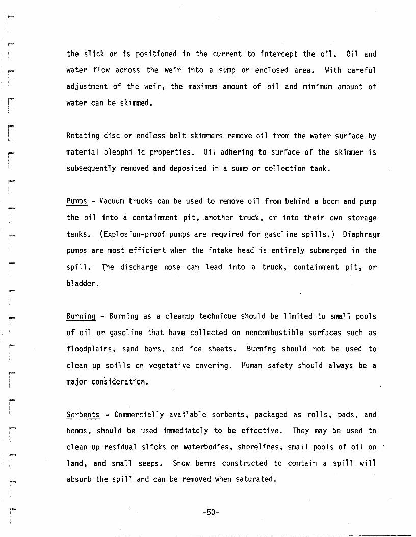
Pumps - Vacuum trucks can be used to remove oil from behind a boom and pump
the oil into a containment pit, another truck, or into their own storage
tanks. (Explosion-proof pumps are required for gasoline spills.) Diaphragm
pumps are most efficient when the intake head is entirely submerged in the
spill. The discharge nose can lead into a truck, containment pit, or
bladder.
Burning - Burning as a cleanup technique should be limited to small pools
of oil or ~Jasol ine that have collected on noncombustible surfaces such as
floodplains, sand bars, and ice sheets. Burning should not be used to
clean up spills on vegetative covering. Human safety should always be a
major consideration.
Sorbents - Corrmercially available sorbents!.- packaged as rolls, pads, and
booms, should be used 'immediately to be effective. They may be used to
clean up residual slicks on waterbodies, shorelines, small pools of oil on
land, and small seeps. Snow berms cons!tructed to contain a spill will
absorb the spill and can be removed when saturated.
-50-

-r
Pumping and Flotation - In areas where a spill may migrate to significant
depths (bogs, sand and gravel bars, elevated pads, etc.), some of the spill
may be forced to the surface by waterflooding the area. Water pumped onto
the area will raise the groundwater table and force the oil to the surface.
Then the oil can be removed with booms, skimmers, and sorbents. In areas
where the contaminated material is consolidated, the water may have to be
pumped into the ground thrQugh one or more holes drilled into the ground
water table. Pumping will lower the groundlwater table, forming a depres
sion that will' trap the spilled oil so that it can be pumped out. The
discharge hose of the pump will be connected directly to at least two large
storage containers. Cessation in pumping before all the oil is removed
will cause the groundwater table to resume its former position and allow
the once-pooled oil to migrate farther in the aquifer. Water used for the
purposes of flooding and pumping should be properly treated before being
discharged.
3.9.2 Implementation Guidelines
Cleanup activities at a given potential spill location may involve several
of the techniques mentioned in the previous discussion. Except where
noted, the procedures can be used throughout the year.
Pads and Roads - Contaminated material on the surface of gravel roads and
pads can bl:! wi ndrowed by a motori zed grader, pi eked up by loaders, and
transported by dump trucks. Small pools on paved surfaces can be cleaned
up with sorbents. Contaminated material along the edges of roads and pads
-51-
.....
-
-
-
-
can be pul"led out with a backhoe or grade-·all or by hand with rakes and
shovels •
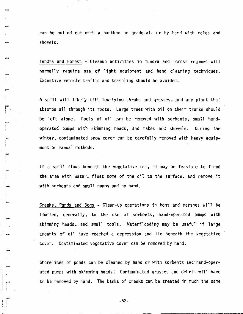
Tundra and Forest - Cleanup activities in tundra and forest regimes will
nonnally require use of light equipment and hand cleaning techniques.
Excessive vehicle traffic and trampling should be avoided.
A spill wi'll likely kill low-lying shrubs and grasses, .and any plant that
absorbs oil through its roots. Large trees with oil on their trunks should
be left alone. Pools of oil can be removed with sorbents, small hand
operated pumps with skirrnning heads, and rakes and shovel s. During the
winter, contaminated snow cover can be carefully removed with heavy equi p
ment or manual methods.
If a spill flows beneath the vegetative mat, it may be feasible to flood
the area w'ith water, float some of the oil to the surface, and remove it
with sorbents and small pumps and by hand.
Creeks, Ponds and Bogs - Clean-up operations in bogs and marshes will be
limited, generally, to the use of sorbents, hand-operated pumps with
skimming heads, and small tool s. Waterflooding may be useful if 1arge
amounts of oil have reached a depression and 1ie beneath the vegetative
cover. Contaminated vegetative cover can be removed by hand.
Shorelines of ponds can be cleaned by hand or with sorbents and"hand-oper
ated pumps with skimming heads. Contaminated grasses and debri s will have
to be removed by hand. The banks of creeks can be treated in much the same
-52-

.....
-
,....
-..-
....
way. In addition, if the creek bed is wide enough, front-end loaders and
drag1 ines can remove 1arge quantities of contaminated sand and gravel.
Small sl icks can be removed from the water surfaces with sorbents, small
skimmers and booms, and hand-operated pumps with skimming heads.
Floodplains and Large Rivers - Spills on the surface of large rivers can be
cleaned up by skimmers used with booms and berms. Rocks and boulders can
be cleaned by hand scraping or pressurized lequipment. Contaminated gravel
bars can be removed with front-end loaders, draglines and backhoes.
Contamination at depth in floodplain gravels can be treated by removing the
gravel, flotation, or pumping. Sorbentbooms and pads should be deployed
around these work areas to prevent contamination of downstream areas.
Breakup poses the greatest hazard to personnel and the 1east success for
cleanup. Little can be done in the case of a spill diTectly into a major
river during breakup, other than cleaning up any residue left on the
floodplain as the river subsides.
Large Lakes. - The primary"means of cleaning up spills or large lakes is the
use of booms, sorbents and skimmers. Contaminated vegetation along the
shore1 ine can be' cl ipped and removed. Sand and gravel can be removed and
replaced •
3.10 DISPOSAL
Provisions for temporary and final disposal of oil and the debris associ
ated with cleanup must be included in a project contingency plan. In most
spill situations, recovered material is temporarily stored at a local site
-53-

.....
-
I""",
while arrangements are made for transport to a final disposal site. Also,
recovered liquid wastes can undergo primary separation to reduce the amount
of liquid 'requiring transport. All disposal plans must be reviewed and
approved byADEC prio'r to implementation.
3.10.1 Oil and Water Separation
Effective oil/water separators can be constructed under field conditions to
recover oil from oil/water mixtures. Fifty-five gallon drums or sheet
metal welded together into a 4 x 8 x 4-foot transportable container can be
used as separators, after being fitted with a bottom draining pipe with
valve. The oil/water mixture would enter the container from the top, be
allowed to settle, and water then drained off the bottom through the drain
pipe. The oil can be pumped to a storage tamk or tank truck.
A second method can be used to remove oil from a natural or excavated sump
pit. A 55-gallon drum fitted with a small pump and hose and a 4- x l8-inch
slot cut from the top third ;s suspended upright into the sump pit,
positioned such that the bottom of the slot remains just below the surface
of the oil layer. Oil flowing into the drum is then pumped into a storage
tank or tank truck.
A tank or any portabl e tank can al so be IJIsed to provide oil/water sepa-
ration. If water in oil emulsions is recovered, chemical de-emulsifiers
can be added to the separator tanks to aid in b'reaking the emulsions and
provi ding more effective water/oil separation.
-54-
-
r
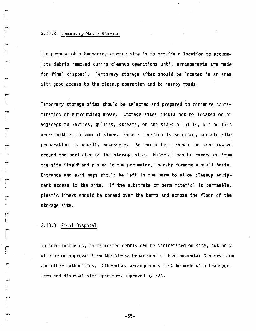
3.10.2 Temporary Waste Storage
The purpose of a temporary storage site is to provide a location to accumu
late debris removed during cleanup operations until arrangements are made
for final disposal. Temporary storage sites should be located in an area
with good access to the cleanup operation and to nearby roads.
Temporary storage sites should be selected and prepared to minimize conta
mination of surrounding areas. Storage sites should not be located on or
adjacent to ravines, gullies, streams, or the sides of hills, but on flat
areas with a minimum of slope. Once a location is selected, certain site
preparation is usually necessary. An earth berm shoul d be constructed
around the perim~ter of the storage site. Material can be excavated from
the site itself and pushed to the perimeter, thereby forming a small basin.
Entrance and exit gaps should be left in the berm to allow cleanup equip
ment access to the site. If the substrate or berm material is permeable,
plastic liners should be spread over the bel~s and across the floor of the
storage site.
3.10.3 Final Disposal
In some instances, contaminated debris can be incinerated on site, but only
with prior approval from the Alaska Department of Environmental Conservation
and other authorities. Otherwise, arrangements must be made with transpor
ters and disposal site operators approved by EPA.
-55-

.....
.....
I"""
I
.~
""'"!l
3.11 RECLAMATION
Initial reclamation of lands affected by spills and cleanup operations
should be aimed at removing structures and equipment used in the cleanup
and at preventing erosion. Techniques for preventing erosion include
tilling or scarifying the surface, mulching, fertilizing, seeding and
transplanting vegetation. These techniques and others are described in a
companion best management practices manual on erosion and sedimentation, I
control. Final reclamation efforts should be postponed unt-il the next
growing season when an evaluation can be conducted to determine whether or
not natural recovery will be sufficient to prevent erosion and allow
development of a satisfactory plant cover.
Restoration activities for affected waterlbodies include removal of any
structures and equipment used during cleanup operations. Excavations in
streambeds shall be sloped to prevent fish entrapment .
-56-

rI
-lI
r
I"""'!I
....
ri
rI
-
Fi
-
REFERENCES
American Petroleum Institute, 1976. Suggested procedure for development ofspill prevention control and countermeasure plans.
Alyeska Pipeline Service Co., 1980. Oil spill contingency plan general·provisions .
Husky Oil NPR Operations, Inc., 1976. Spill prevention control andcountermeasure plan for Lonely POL facility ..
Kl i pp, J. E., 1973. Oil spill contingency and response pl an for a proposedpipeline system, Colony Development Operation.
Woodward-Clyde Consultants, 1979. Manual of practice for protection and cleanupof shorelines: Volumes I and II.