division 33 water mains / service lines 33.01 scope
TRANSCRIPT

Rev. 8/94 33 - 1
DIVISION 33 WATER MAINS / SERVICE LINES
33.01 SCOPE: The Contractor shall furnish all labor, material, equipment and supplies and shall perform all work necessary for the complete installation of the water main, water service lines and associated items, including all specified testing. The water main shall be constructed to the alignment shown on the approved construction plans, as well as size and type shown or specified. All materials for the water mains, service lines and associated items furnished by the Contractor shall be new and shall be as specified herein.
A. Pipe to be supplied with special locking or flexible type joints, or especially
fabricated sections will be specified or detailed on the plans. See other sections of these specifications as applicable.
B. Pipe stronger than that specified herein may be furnished at the Contractor’s
option and at no additional cost to the City, provided such pipe conforms in all other respects to the applicable provisions of these specifications.
C. The Manufacturer and Contractor shall use equipment and methods adequate to
protect pipe, joint elements, and coatings, from damage during hauling, storage and handling. When there is reasonable doubt as to the structural strength or water tightness of damaged sections, those sections will be rejected and replaced at the Contractor’s expense.
D. All Standards referenced shall be the latest edition.
E. Any proposed deviations from the listed materials must be approved by the
Engineer prior to ordering.
F. Valves on existing mains shall be operated only by authorized representatives of Public Utilities.
33.02 PIPELINE MATERIALS:
A. Ductile Iron Pipe shall be furnished in 18 or 20 foot laying lengths, with push-on type joints, except where mechanical joint or pipe is called for on the plans. Ductile iron pipe shall conform to the requirements of AWWA C151. Flanged ductile iron pipe shall comply with the requirements of AWWA C115.
1. Thickness Class of the pipe shall be Pressure Class 350 as required by the
pipe size, bedding type and depth. The pipe shall be round and gaged

Rev. 8/94 33 - 2
throughout its entire length. Ungaged pipe will not be accepted. 2. Lining – All pipe shall be single coat cement lined and sealed coated in
accordance with AWWA C104. 3. Joints shall be either mechanical, push on, or flanged conforming to
AWWA C111 (ANSI A21.11) or AWWA C115 (ANSI A21.15) as applicable.
All flanges and glands for pipes and fittings shall be made of ductile iron.
4. Fittings shall be manufactured in accordance with AWWA C110 (ANSI
A21.10) or AWWA C153 (ANSI A21.53), and shall be ductile iron. The minimum acceptable pressure rating shall be 350 psi. All fittings shall be lined in the same manner as ductile iron pipe.
5. Coating shall be provided on the exterior of all ductile iron pipe, joints and
fittings as required by AWWA C110, C111, C115, C151, or C153 as applicable. All pipes, joints and fittings shall be examined before and after laying to determine if the coating has been damaged. Any damaged areas and all joints shall be coated with approximately 1 mil of a bituminous coating, such as Koppers No. 50 or Intertol No. 49.
6. Polyethylene Wrap shall conform to the requirements of AWWA C105.
7. Retainer Glands shall be cast from high strength ductile iron. The gland
shall be compatible with mechanical joint connectors meeting the requirements of AWWA C111. Acceptable types shall be:
a. For PVC pipe, Uniflange Series 1300 or EBAA Iron Sales, Inc.,
Series 500 or 1500; b. Ductile Iron Pipe shall include a restraining mechanism which,
when actuated, imparts multiple wedging action against the pipe, increasing its resistance as the pressure increases. The gland shall be compatible with mechanical joints meeting the requirements of AWWA C111. Acceptable types shall be Mega-Lug Series 1100.
B. PVC Pipe shall be only used on pipelines smaller than 12 inches nominal
diameter. The outside dimension of the pipe shall be identical to that of ductile iron pipe. The pipe shall be provided in standard 20 feet lengths. Pipe shall conform to AWWA C900.

Rev. 8/94 33 - 3
1. Pressure Class of the pipe shall be 150 psi (DR 18). 2. Joints shall be push-on types. Solvent weld joints may not be used.
3. Fittings shall be identical to those provided for iron pipe. (Reference
Paragraph 33.02-A.4.)
4. Unless otherwise noted on the plans or directed by the Engineer, PVC pipe shall be used with a thrust block, and the Star Retainer – Series 1300 Restrainer as manufactured by the Uni-Flange Corporation, or approved equal.
5. Two-inch PVC pipeline shall conform to the requirements of AWWA
C901, formula PE 3406, Pressure Class 160. Joints shall be push-on type. C. Sleeves and Couplings:
1. Mechanical joint sleeves shall be solid type, long pattern, manufactured in accordance with ANSI/AWWA C110. Sleeves shall be of ductile iron with a minimum pressure rating of 350 psi. Glands shall be of ductile iron. Bolts and nuts shall be low-alloy steel or cast-iron except when otherwise specified. Glands, gaskets, bolts, and nuts shall be in accordance with AWWA C111 (ANSI A21.11). Generally, mechanical joint split sleeves shall not be used except as noted below.
Sleeves should not be machined in order to facilitate use with pipe of a class or type other than that for which the sleeve was intended. If machining is required, it must be approved by Public Utilities prior to use.
2. The use of bolted steel couplings shall be restricted to joining pipes of
different outside diameters, joining pipes of dissimilar materials, and joining section of steel pipe. Ferrous surfaces shall be coated with an epoxy coating. Enamel coatings are not acceptable. Bolted steel transition couplings shall be Rockwell 413, Dresser Style 162, or approved equal.
Bolted steel reducing couplings shall be Rockwell 415, Dresser Style 62,
or approved equal. Bolted steel couplings for joining pipes of the same outside diameter shall
be Rockwell 411, Dresser style 38, or approved equal. In those cases where the manufacturer lists two or more coupling lengths for a given type, the longer or longest listed length shall be used.

Rev. 8/94 33 - 4
D. Tapping Sleeves:
1. For All Pipelines - Tapping sleeves shall be split sleeve with mechanical joint-type end seals. Cast sleeves for tapping cast iron pipe, shall be of ductile iron meeting ASTM A536 Grade 65-42-12. Cast tapping sleeves for use on all pipes shall as manufactured by American Darling, Mueller Co., or approved equal.
2. Gaskets shall conform to applicable requirements of AWWA C111, and
shall be clearly marked to identify the diameter range for which intended. 3. Outlet Flange shall be 125 pound, drilling per ANSI B16.1, with standard
tapping flange counterbore per MSS SP-60. 4. Mechanical Joints, Bolts and Nuts shall conform with ANSI/AWWA
C111/A21.11. 5. Exterior Coatings shall be asphaltic varnish per Federal Specification TT-
V-51, Military Specification MIL C-450, or the manufacturer’s standard or optional coating as stated herein.
6. Valves shall be tapping flange mechanical joint bell unless shown
otherwise on the plans. With the exception of seat rings and body flange, all other features of the valve shall be in accordance with the requirements for double disc gate valves.
E. Valves:
1. General – All valves for buried service 4-inch and larger shall be provided with a 2-inch square operating nut.
All valves shall open right (clockwise). All valves shall be rated for a
minimum working pressure of 200 psi for valves 4 to 10-inch, 150 psi for valves 12-inch and larger, and shall be suitable for buried service.
Valve ends shall be flanged, mechanical joint or mechanical joint x flange
to suit pipe or fittings as shown on the plans and shall conform to the requirements of ductile iron pipe.
2. Double Disc Gate Valves shall be used for pipelines from 4 inches up to
and including 10 inches in diameter, and shall conform to AWWA C500. These valves may also be used on larger pipe if used in conjunction with a tapping sleeve.

Rev. 8/94 33 - 5
Gate valves shall be double disc type, iron body, non-rising bronze stem, with an O-ring stuffing box and shall be suitable for buried service.
Gate valves shall be Darling No. 55, Smith “Hydrogate”, Mueller A2380 or Kennedy.
3. Rubber-Seated Butterfly Valves shall be used on pipelines 12 inches and
larger in diameter, and shall conform to AWWA C504. Unless otherwise indicated, butterfly valves shall be short-body, Class 150B and suitable for buried service.
Manual operators shall be of the traveling nut or worm gear-type, sealed,
gasketed, and lubricated for underground service. The valve shall be operable with a minimum input of 150-foot pounds on
the operating nut, and capable to withstand an overload input torque of 450-foot pounds at full open and full closed positions without damage to the operator or valve.
The disc shall be capable of holding in any intermediate position without
creep or flutter. Valves shall be American Darling Class 150, Mueller “LineSeal III”,
Kennedy “ADAP-TORQ”, or M&H Valve. 4. Coatings – All interior ferrous surfaces of all butterfly valves shall be
coated in accordance with ANSI/AWWA C550 using a coating approved by the Virginia Department of Health for contact with potable water and shall not contain lead, coal tar resins, lamp black, carbon black or Bituminous materials.
The exterior surfaces shall receive two coats of a heavy coal tar coating or
an asphaltic varnish or the manufacturer’s standard exterior coating. 5. Brass Gate Valves (2”) – For use on meter assemblies, 2-inch mains, and
blow-offs shall be NIBCO Model T113-T or equal. Valve shall be of the non-rising stem, solid wedge, “T” handle type. Valve shall open left (counter-clockwise).
F. Fire Hydrants:
1. General – The hydrant base shall have a 6-inch mechanical joint bell, designed for connection to a horizontal 6-inch ductile iron pipe hydrant branch.

Rev. 8/94 33 - 6
a. The traffic coupling shall allow for 360-degree adjustment of the
upper standpipe. b. They hydrant shall be painted with Glidden Rustmaster, Metallic
Pure Aluminum Point (#Y-592). Paint is to be applied in accordance with the applicable sections of Division 41.
c. Operating nut shall turn clockwise to open hydrant. d. Extension spools shall be available from 6 inches to at least 48
inches, in 6-inch increments. Normal bury depth shall be 3.5 feet.
2. Hydrant Standards – Fire hydrants shall be of the dry barrel type and shall conform to AWWA C502.
a. Minimum flow rate shall be 1000 gallons per minute with not more
than 5 psi pressure drop through the steamer nozzle. b. Internal valve shall be 4½ inches in diameter and have bronze to
bronze seating. c. Nozzles: Two hose nozzles placed 180 degrees apart; 2½ inch
National (American) fire hose coupling screw threads. One steamer nozzle with 4½ inch National (American) fire hose coupling screw threads.
Fire hydrants shall be Mueller Centurion – A421, American Darling Mark-73, Kennedy Guardian K-81, or M&H Reliant Style 929, Metropolitan 4½”.
G. Valve Boxes: Valve boxes shall be City Standard VB-1, of Public Facilities
Manual, Volume II. Valve boxes and lids shall be manufactured from cast iron meeting ASTM A-48, Class 30. Casting shall be dipped in an asphaltic coating.
H. Air Vents: All air vents shall be tapped with a standard two-inch corporation tap.
All materials and construction shall be as shown in figure S-3, Air Vent Detail in the Public Facilities Manual, Volume II.
I. General: Steel pipelines are not standard and will only be installed where shown
on the plans.

Rev. 8/94 33 - 7
1. Steel Pipe for use in water pipelines shall be electrically butt-welded straight-seam, or seamless pipe. Steel pipe 6 inches and larger shall be in accordance with AWWA C200. Wall thickness, and exterior and interior coatings shall be as shown on the plans. Field welding of steel water pipe shall be in accordance with AWWA C206.
2. Interior Coating – The interior coating of all steel water lines shall be
coated with an epoxy coating system to a thickness of 14 to 24 mils. The coating must be approved by Virginia Department of Health for contact with potable water and shall not contain lead, coal tar resins, lampblack, carbon black or Bituminous materials.
J. Brass Pipe shall be red brass pipe meeting the requirements of ASTM B 43. Pipe sizes, wall thickness and dimensions shall meet the requirements of ASTM B 251 Table I for regular pipe. Brass pipe fittings shall be screwed end malleable iron pattern meeting the requirements of ANSI B16.15. They shall be finished rough, unless otherwise specified. Unions shall be of all brass or bronze with ground joints and shall be left semi-finished. Fittings shall be rated for steam working pressures finished. Fittings shall be rated for steam working pressures up to 125 psi. Joints shall be screwed type with threads clean cut, tapered and smooth, meeting the requirements of ANSI B2.1.
33.03 PIPELINE INSTALLATION
A. Reference Standards: The work shall be performed in accordance with the application sections of the following standards and regulations:
1. AWWA C600 2. AWWA C651 3. AWWA C105 4. AWWA C111, APPENDIX A 5. AWWA C115, APPENDIX A 6. AWWA C500, APPENDIX A 7. AWWA MANUAL M17 8. AWWA MANUAL M23 9. WATERWORKS REGULATIONS 10. PUBLIC FACILITIES MANUAL, VOLUMES 1 & 2
B. Required Submittals and Construction Records:
1. In all cases the Contractor shall submit the following for review and approval by the Engineer:
a. Material affidavit for all materials furnished. The affidavit shall

Rev. 8/94 33 - 8
include all of the following:
1) Name and location of work; 2) Name and address of Contractor; 3) Quantity and date or dates of shipment and/or delivery for
each item; 4) Manufacturer, Model No. and/or product description for
each item provided; 5) Signature of an officer of the manufacturing, fabricating or
supplying company, on a company standard form certifying that the listed materials were provided.
b. Construction records and specified data for installed valves and
fire hydrants. The dimensions and data may be clearly indicated on prints of the Contract Drawings or separate sketches as appropriate.
1) Locations of horizontal bends, vertical offsets, valves, ends
of installed lines, and corporations with dimensions referenced to existing mains, property lines, curb lines, or other permanent objects.
2) Data for valves installed – date set, cover, size,
manufacturer, number of turns to open, direction of opening, and joint types.
3) Data for hydrants installed – date set, manufacturer, depth
of bury, distances main to valve, and valve to hydrant. 4) Any sheeting left in place.
c. Flushing sequence to be used prior to disinfection.
2. In those cases where the installation or procedure proposed is not detailed
on the plans or in the specifications; or a significant modification is required, the Contractor shall submit the following for review and approval by the Engineer:
a. Procedures and equipment to be used for pressure testing, leakage

Rev. 8/94 33 - 9
testing, and disinfection. b. Detailed drawings and method of joint or pipe restraint. c. Method of installing polyethylene tube or sheet material for pipe
encasement. d. Detailed drawings of proposed modifications, off-sets or special
fittings and method of installation. C. Line and Grade: All pipes shall be laid to line and grade as shown on the plans
and as specified herein. Normally, the grade at the top of the proposed pipeline is determined by surface grade and cover requirements.
1. Careful attention shall be given to the depth of new pipelines at points
where tie-ins to existing mains are to be made. The existing main shall be uncovered in the presence of the Inspector and the new pipeline set to proper elevation to provide for a perpendicular and level tie-in. Obstructions within the tie-in length may require special offsets by the Contractor.
2. The Contractor shall investigate the proposed location of the main far
enough in advance of the work to determine where conflicts will occur and to determine joint deflections necessary to clear any obstructions.
Normal cover (top of pipe to ground or pavement surface) for water mains shall be 36 inches. If an obstruction is encountered the Contractor may install the pipe with cover of from 24 inches minimum to 48 inches maximum. Where obstructions indicate that either the minimum or maximum cover will be continuous for a horizontal distance of greater than 162 feet (9 pipe lengths), the Department of Public Utilities shall be notified before installation begins, at which time the situation will be assessed for possible modifications. All changes will necessitate plan revision with must be approved prior to installation.
3. PVC Pipe (C900) shall not be utilized if the depth of cover will be less
than 30 inches.

Rev. 8/94 33 - 10
D. Separation of Water Pipelines and Sanitary Sewers and Laterals:
1. General – Virginia Health Department Regulations require that water mains be installed with 10 feet minimum horizontal separation and 18 inches minimum vertical separation. In areas where sanitary sewerage facilities exist prior to a water main installation, the Contractor shall install the water pipeline and/or replace portions of the sanitary sewer mains and laterals in compliance with the provisions of this section.
2. Parallel Separation – Except as shown on the plans, or otherwise directed
by the Engineer, water lines shall be laid at least 10 feet horizontally from existing or proposed sanitary sewer lines. This distance shall be measured edge to edge. Should local conditions prevent a lateral separation of 10 feet, a water line may be laid closer than 10 feet to a sewer lateral or sewer line if the top of the sewer pipe is at least 18 inches below the bottom of the water line. Where this vertical separation cannot be attained, the sewer line shall be constructed of “water quality” pipe and pressure tested at 50 psig for 30 minutes to assure water tightness prior to backfilling.
3. Vertical Separation – Water lines crossing sanitary sewer lines or laterals
shall be laid to provide a separation of at least 18 inches between the bottom of the water line and the top of the sewer line.
Where this separation cannot be attained (such as compliance with 24
inches minimum cover on the water line) the sewer line shall be constructed of water quality pipe, or in the case of existing sewer lines, the existing sewer shall be replaced with “water quality” pipe for a distance of 10 feet on each side of the crossing. Also a full (18-foot minimum) length of water main shall be centered on the crossing so that the joints will be as far as possible from the sewer.
Water mains shall not pass through nor come in contact with any part of a
sanitary sewer, combined sewer, or sewer manhole. 4. Sewer Line Replacement – In those cases where the water line must cross
above a sanitary sewer or house lateral, and the bottom of the water line is less than 18 inches from the top of the sewer, the Contractor shall remove a suitable length of the sewer line and replace it with ductile iron or PVC-C900 water quality pipe of the same nominal diameter as the sewer line.
The pipe shall be joined using suitable transition couplings of rubber or neoprene material and stainless steel circumferential clamps.

Rev. 8/94 33 - 11
In those cases where the water line must pass beneath an existing sewer the water line shall be installed with a minimum distance of 18 inches from the top of the water line to the bottom of the sewer; and, in addition, a suitable section of the sewer shall be replaced with water quality pipe as described above.
E. Material Handling:
1. The pipe and fittings shall be handled and protected during loading, transporting and unloading operations in such a manner as to avoid damage. Pipe and fittings shall be unloaded by lifting with hoists or skidding so as to avoid shock, damage, or contamination. Under no circumstances shall the pipe or fittings be dropped nor shall they be permitted to roll against pipe already on the ground.
Insofar as practical, each piece of pipe shall be delivered and unloaded near the place where it is to be installed and where it will not interfere with excavation, traffic, or adjacent property owners. All damage pipe and fittings will be rejected and such rejected pipe and fittings shall be removed from the site as directed by the Engineer. In the event of slight damage to be repaired on the site. Such repairs shall be made at the Contractor’s expense.
2. Cleaning and Inspection of Pipes and Castings – The inside of pipes and
castings shall be thoroughly cleaned before laying and shall be kept clean until accepted in the completed work. Whenever the work is interrupted, all open ends of pipe shall be temporarily blocked with plugs. All pipes and special castings shall be carefully examined for defects, defective pipes and castings shall not be installed. If any such pipe or casting is discovered after placement, it shall be removed and replaced with an acceptable pipe or casting by the Contractor at his own expense.
F. Earthwork:
1. Trench Excavation – Excavation shall conform to the lines and grades shown on the plans and established by the Contractor. No trench shall be opened more than one hundred (100) feet in advance of the completed pipe work without the written permission of the Engineer. The lines of excavation of trenches shall be made so there will be a clearance of at least eight (8) inches on each side of the barrel of pipe to the grades shown on the profile and established by the Contractor. Excavation shall not be carried below the established grades and any excavation below the required level shall be backfilled, and tamped at the Contractor’s expense.
Rev. 8/94 33 - 12
The bottom of pipe trenches shall be accurately cradled and shaped to fit the barrel of the pipe for a depth of 0.1 times the outside diameter of the pipe to such that the full length of the barrel of the pipe will rest uniformly in the trench bottom, with bell holes excavated accurately by hand.
The Contractor shall do all sheeting, bracing, and shoring necessary to perform the work and protect workers and excavations as required to conform to all governing laws and ordinances and as directed by the Engineer. The Contractor shall erect, maintain and safeguard temporary bridges, walkways, or crossings where it is necessary to maintain traffic. Where trenches are open in the vicinity of pedestrian or vehicular travel lanes, suitable barriers will be constructed and maintained and the work will be further protected from sunset to sunrise with a sufficient number of lights or flares to fully protect the public from accidents or account of construction of pipe lines or appurtenances. All necessary dewatering and pumping shall be performed in such a manner as to keep the trench in a satisfactory condition for pipe laying. The Contractor shall conduct his operations such as to provide adequate drainage of the construction area and adjacent areas affected by construction through temporary ditching, piping or other means as may be appropriate. Drainage shall not be impeded by construction operations.
2. Backfilling shall be done with material free from large clods and foreign
matter, and shall evenly and carefully be placed around and over the pipe in six (6) inch maximum layers, each layer being thoroughly and carefully tamped until twelve (12) inches of cover exists over the pipe. The remainder of the backfilling may be placed in twelve-inch (12”) horizontal layers.
Tamping shall be performed on each layer using suitable compactors.
Compaction equipment specifically designed for these purposes must be present and operational at the job site and shall be utilized throughout the length and depth of the trench to obtain uniform compaction. It shall be the Contractor’s responsibility to provide compaction of the backfill material to 95% of its maximum density as determined in accordance with VTM-1 (VDOT) at the optimum moisture content within plus or minus 20% of its optimum moisture. Surplus materials shall be disposed of by the Contractor. Pavement and shoulders are to be cleaned of excess material immediately after backfill.
3. Compaction Tests – The City, or its authorized representatives, reserve the
right to perform compaction tests on any or all portion(s) of backfill

Rev. 8/94 33 - 13
placed in the trench at no costs to the Contractor. However, in the event the compaction of this backfill is not in compliance with the Specifications then the Contractor shall take corrective measures at no costs to the City to bring the backfill within the limits of the Specifications. The Contractor shall then be responsible for reimbursing the City all costs associated with the performance of compaction test(s) in those sections of the backfill that failed the compaction test(s). However, if the test(s) should indicate compaction within the required limits, the City will then be responsible for cost.
G. Sheeting Left in Place:
1. Should it be determined that removal of sheeting in excavated areas might endanger adjacent properties or structures, the Engineer may direct that the sheeting be left in place. In such instances, sheeting will be cut off one (1) foot below grade and left in place. Backfilling will be performed in accordance with appropriate sections of this specification.
2. Payment for sheeting left in place at the direction of the Engineer shall be
made in an amount equal to the cost of materials, as evidenced by the Contractor’s invoices, plus fifteen (15%) percent.
H. Sub-Surface Utility Warning Tape: All non-ferrous water mains shall be
identified by a sub-surface utility warning tape placed at an elevation not less than six (6) inches, nor more than twelve (12) inches below the proposed finished grade. The utility warning tape shall be manufactured by Griffolyn Co., or approved equal. The tape shall be of a durable, metalized, plastic film similar to Terra Tape D for identification of water mains; bright blue tape imprinted with the legend “Caution – Waterline Below” shall be used.
I. Field Cutting Pipe: Pipe may be cut using methods approved by the pipe
manufacturer. Cuts shall be made at 90 degrees with the centerline of the pipe so that a framing square placed against the side of the pipe will reveal not more than ¼ inch variation across the diameter of the pipe in any direction. Cut ends and rough edges shall be ground smooth and for push-on type connections, the cut end shall be beveled slightly on the outer edge.
Pipe coatings damage din handling or during the cutting operation shall be
touched up and repaired prior to installation. J. Joint Assembly: Gaskets and joint assembly shall be in accordance with AWWA
C111 or the manufacturer’s recommended procedures, if more stringent.

Rev. 8/94 33 - 14
Both the gasket and plain end of the pipe shall be thoroughly cleaned to remove all loose rust and foreign material. Just prior to assembly, both the gasket and the plain end shall be brushed with soapy water or approved pipe lubricant.
1. Joint Deflection at any single joint shall not exceed 80 percent of the
manufacturer’s allowable deflection for the type of joint to be used. When joint deflections are required the pipe shall be inserted straight into
the bell and the pipe deflected after complete insertion. 2. Mechanical Joint – T bolts (or tie bolts) shall be alternately and uniformly
tightened to insure that the gland compresses the gasket evenly around its perimeter.
Nuts shall be gradually tightened to the torque ranges as follows:
Pipe Size Bolt Diameter Range of Torque
(ft. lb.) 4” – 24” ¾” 75 – 90 30” – 36” 1” 100 – 120 42” – 48” 1¼” 120 – 150
Bolts of stainless steel or other corrosion control steel alloys shall be used when specifically called for on the plans or stated herein.
K. Joint Restraint:
1. Concrete Buttresses and concrete anchors shall be placed where indicated on the plans or as required herein. Concrete buttress and anchors shall be carefully formed as required to prevent the joint gland or fasteners from being embedded in concrete and therefore accessible for future repairs. Alternate forming requirements must be approved by the Engineer prior to installation.
Concrete shall be ready-mixed concrete conforming to ASTM
Specification C-94. All concrete shall be Class A-3 and shall develop a compressive strength of 3000 psi at twenty-eight (28) days. The slump range for the concrete shall be three (3) inches to four (4) inches. Concrete admixtures as per Division 36 of these Specifications may be used to provide workability.

Rev. 8/94 33 - 15
Concrete shall be conveyed from the mixer to the place of final deposit by methods which will prevent separation or loss of materials. Adequate equipment shall be provided for heating the concrete materials and protecting the concrete during freezing or near freezing weather as per Division 36.
2. Restraining Rods shall be installed as shown on the plans or as directed by
the Engineer. Tie-bolts, threaded rods, couplings, nuts, washers and clamps used for rodding shall be manufactured expressly for use in restraining underground pipelines and shall be installed as recommended.
ALL RODS AND FASTENERS SHALL BE COATED WITH TWO
COATS OF BITUMINOUS PAINT BEFORE BACK-FILLING THE TRENCH. As a minimum, the rods shall have a minimum yield strength of 36,000 psi.
3. Retainer Glands shall be installed where indicated on the plans or as
directed by the Engineer, either as the primary method of restraint or as a supplement to concrete blocking, or other methods.
Retainer glands shall be carefully installed to properly compress the
gasket. Peripheral set bolts shall then be tightened gradually to the manufacturer’s recommended torque, and in a manner that the circumferential alignment of the joint will not be altered.
4. Temporary Blocking may be of heavy timber, steel, or other materials and
shall be of sufficient strength and securely braced or supported so as to prevent any movement of the pipe or fittings. Poured in place concrete shall not be used.
The Contractor shall be solely responsible for the adequate restraint of
pipe and fittings during pressure testing or during any other procedure requiring that the pipeline be pressurized prior to final acceptance by the City.
L. Installing Valves: Valves shall be installed at the locations shown on the plans or
as otherwise directed by the Engineer.
Valves will be set with the operating stem truly plumb. The top of the operating nut shall be not more than 4 feet below the top rim of the valve box when said box is properly installed to finished grade. Valve stem extension devices shall not be used. Valves shall be supported by a gravel bed and shall not be supported by the pipeline.

Rev. 8/94 33 - 16
M. Installing Fire Hydrants: Hydrants shall be installed at the locations shown on the
plans or as otherwise directed by the Engineer.
Hydrants shall be set with their vertical axis truly plumb, and in accordance with Standard Drawings in Public Facilities Manual, Volume II, as applicable. The hydrant branch valve shall be set in accordance with Paragraph L above. Generally, in those cases where a parallel ditch exists between the pavement or shoulder and the proposed hydrant, and the depth of that ditch is greater than 18 inches (edge of shoulder to flow line of ditch), a pipe culvert, or an extension of an existing culvert, will be required. When shown on the plans, the culvert pipe of the type, diameter and length indicated, shall be installed. For payment purposes the culvert installation and backfill will be considered a part of the complete hydrant installation. Special close-coupled or offset hydrant branch installations will be detailed on the plans. In the event that an obstruction is discovered during excavation, which requires that the standard or detailed hydrant branch be modified, the Contractor shall submit a workable design for approval by the Engineer. Newly installed fire hydrants not yet in service shall be covered with a bag or sheet material, securely tied in place; indicating to fire fighters that hydrant is not usable. Cover shall be removed as the line is activated.
N. Appurtenances:
1. Blow-off: All dead-end lines shall be equipped with a permanent blow-off. A two-inch blow-off shall be provided on all lines and shall be installed as shown on Figure BOV-1, of Public Facilities Manual, Volume II.
2. Air relief assemblies required on the plans or installed by the Contractor,
with the approval of the Inspector, to facilitate air removal shall be installed in accordance with Standard Drawing S-3.
O. Polyethylene Encasement: Encasement of the pipeline shall be installed as shown
on the plans or as directed. In the event that corrosive soils (as defined by Appendix “A” of the ANSI/AWWA C105/A21.5) are encountered during excavation, the Engineer may direct that all, or a portion, of the pipeline be encased, whether or not encasement was indicated on the plans.
P. Pressure Tests: All newly laid pipe shall be subjected to a hydrostatic pressure of

Rev. 8/94 33 - 17
1.5 times the expected working pressure, or 125 psig, whichever is greater, measured from the high point in the line. Tests for leakage shall be conducted concurrently with the pressure test. Pressure tests shall be of at least a two (2) hour duration, shall be in accordance with AWWA C600, except as modified herein; and must be witnessed by authorized personnel of the City.
1. Gauges and Equipment – The Contractor shall furnish all pumps, fittings
and gauges as necessary to fill the line with potable water, dispel air from the system, and pressurize the pipeline for the tests. The Engineer reserves the right to test gauges on a dead weight tester to determine their accuracy. The Contractor shall provide and install an approved backflow preventer in the water supply line, between the newly laid pipeline and the existing distribution system.
2. Water for pressure tests will be charged to the Contractor. The charge will
be calculated using current rates for water consumption. 3. Pressure tests shall not be conducted against closed valves other than
blow-off valves and hydrant foot valves. 4. Evaluation of Pressure and Leakage Tests – After the specified pressure is
attained and stabilized, any pressure drop during the duration of the test will be considered as test failure.
If the pressure is higher than required at the start of the test, it will be the
base pressure for determining compliance. Any leakage, either visually evident, or evident due to pressure drop
during the test, shall be considered test failure. The Contractor shall repair and correct any and all leaks in order to achieve a successful pressure test.
Q. Disinfection of Water Mains:
1. Flushing – All mains shall be thoroughly flushed with a full pipe diameter discharge, using potable water prior to the introduction of disinfecting agents. Velocity in the main during flushing shall attain a velocity of 2.5 feet per second for a period sufficient to remove sediment and discolored water from the main. All valves and hydrants shall be operated and flushed.

Rev. 8/94 33 - 18
Flushing shall progress in a logic sequence (approved by the Engineer) from the source of water to the end of the installation, without flushing dirty water through portions that have already been flushed. Water for the initial flushing and flushing after chlorination will be furnished by the Owner, with charges rendered as noted above. It is the Contractor’s responsibility to provide adequate drainage for the discharge without causing a public nuisance.
2. Chlorination of the main and appurtenances, and favorable bacteriological
analysis received from samples collected therefrom, shall be completed before any newly laid pipeline is connected to the potable water distribution system.
All work shall be in accordance with AWWA C651, and as specified
herein. The Contractor shall provide all equipment and materials for disinfection and testing for chlorine residual. Chlorine residual testing shall be done by either the DPD or Amperometric Titration methods.
3. Chlorination shall be by the continuous feed method. Potable water shall be introduced into the pipeline at a constant flow rate.
An approved double-gate – double-check valve backflow preventer shall be installed in the source line to protect the existing distribution system. Chlorine shall be added at a constant rate (using equipment specifically designed for the purpose), proportional to the water flow, so that the free chlorine concentration in the water main is at least 25 mg/1. Additional chlorine may be required depending on-site specific conditions.
The chlorinated water shall remain in the pipeline for at least 24 hours,
after which time the residual chlorine content shall be at least 10 mg/1. All valves and appurtenances shall be operated while the heavily chlorinated water remains in the pipeline.
4. After the required retention time the heavily chlorinated water shall be
flushed from the main, using potable water. However, the highly chlorinated water shall not be flushed out until the residual is less than 20 mg/1.
Disposal of the heavily chlorinated water is the responsibility of the
Contractor and shall be in such a manner as to cause no adverse environmental effects such as fish kills or erosion and in compliance with all federal, state and local requirements.
5. The Contractor shall provide sampling taps as specified in Section 7.3 of

Rev. 8/94 33 - 19
AWWA Specification C-651. A minimum of two (2) sampling taps shall be located as directed for any pipe being sterilized less than 1000 feet. For pipe installation greater than 1000 feet the Contractor shall provide one (10 tap for each 1000 feet of, or fraction thereof, plus one (1) tap. In the event the line branches, at least one (1) tap will be made on each branch line.
The standpipes with wheel valves or cut-offs attached to the water mains to facilitate testing shall not be exposed above ground at any time except while collecting samples. They should be enclosed in a box below ground. After completion of the tests, the wheel valve and the standpipe shall be removed. The standpipe shall be removed by cutting off at the corporation tap.
6. A minimum of two samples taken 24 hours apart shall be collected from
each section of pipeline and delivered to the Department of Public Utilities, City of Chesapeake, for testing purposes. All samples must successfully pass bacteriological testing prior to placing the pipeline in service. If additional testing is required, the Contractor is responsible for the water main and testing at no cost to the City until the samples pass the above requirements.
Chlorine residual measurements shall be taken and recorded at the time
each sample is collected. 7. If the line is not activated within three weeks of the date of the final
sample passed, the line shall be resampled in accordance with Paragraphs 5 and 6 above. If any sample fails, the entire pipeline shall be re-disinfected in accordance with this Section.
R. Tie-Ins to Existing Mains:
1. General:
a. All materials shall be installed in accordance with the manufacturer’s recommendations including, but not limited to, alignment, torque requirements, tolerances, etc.
b. All materials shall be thoroughly disinfected before they are
installed. c. No tie-in shall be made except in the presence of the Inspector.

Rev. 8/94 33 - 20
d. Final tie-in shall not be made until the bacteriological samples collected following disinfection of the new main have indicated no contamination.
e. Disinfection shall be performed in accordance with Sections 9 and
10 of AWWA C-651 as applicable.
2. Tapping Existing Mains Under Pressure:
a. General; Tapping sleeves and valves shall be utilized for connecting to existing mains when shown on the plans, or when in the opinion of the Engineer, the use of other methods would require interruption of water service to an extent considered undesirable.
b. Sleeve to Joint Distance: The center line of a tapping sleeve and valve assembly shall be located a minimum distance from an existing pipe joint as follows:
Size of Tapping Sleeve Min. Distance Centerline Of Sleeve to “Home Line”
Of Existing Joint
4”, 6” & 8” 3 feet 10”, 12” & 16” 5 feet
In cases where the horizontal alignment as shown on the plan would result in a “sleeve to joint” distance less than the minimum stated above, the Engineer may direct the substitution of a MJ x MJ x FL tee connection, using suitable sleeves and nipples.
When, in the opinion of the Engineer, offsets or modifications to new pipeline alignment are required, sub-surface investigations, submittals for modifications, etc., shall be in accordance with the other requirements of this Division.
c. Outside Diameter of Existing Mains: It shall be the Contractor’s responsibility to determine the outside diameter at the location of the proposed tap in order that the tapping sleeve or couplings to be provided can be properly installed.
d. Pressure Testing: In addition to pressure testing of newly installed
pipelines, each tapping sleeve and valve assembly shall be tested

Rev. 8/94 33 - 21
prior to making the tap. Water shall be injected into the body of the sleeve, to a pressure of 125 psig, through the test plugs. If test plugs are not provided in the sleeve, a tapped mechanical joint plug shall be assembled to the valve for testing purposes. Pressure shall be maintained for a one-hour period without evidence of leakage. This test must be witnessed by authorized personnel of the City. A satisfactory test shall be completed before beginning the tapping (cutting) operation.
e. Restraint: All installed tapping sleeves shall be restrained by
concrete buttresses. Concrete dimensions for a tapping sleeve and valve shall be as tabulated for a tee fitting with like nominal diameters of run and branch. Fasteners and glands shall be coated with a bituminous coating or shielded with polyethylene film to prevent a bond between the concrete and the sleeve components.
f. Tapping: Upon completion of the tap the Contractor shall save the
coupon to show the Inspector.
3. Sleeve-In of Straight Pipes:
a. Sleeve-in connections shall be used whenever possible to reduce head loss in the system.
b. Materials used for the sleeve shall conform to the requirements of
this Division of this Specification.
4. Upon completion of the tie-in, it shall be flushed to remove the highly chlorinated water. One sample for bacteriological examination shall be collected from the point of discharge of the flushing water. The requirements of Division 33.03-Q shall apply except as modified above.
S. Shut-Down for Main Adjustment or Tie-Ins: Main adjustment work shall be permitted only between eleven (11) p.m. and five
(5) a.m. from Tuesday through Thursday. Contractor must coordinate this work with the Departments of Public Works, Public Utilities and Fire Department, and provide forty-eight (48) hours notice prior to doing any such work. Contractor must notify the affected customers at least twenty-four (24) hours before the shutdown of the water system. All fittings and pipe work necessary to complete the adjustment must be assembled and finished above ground prior to the shutdown of the water system, unless otherwise approved by Public Utilities.

Rev. 8/94 33 - 22
T. Abandonment of Existing Pipe in Place: In the event that an existing pipe is abandoned as the result of the installation of
new pipe, the ends of the abandoned pipe shall be capped or plugged. All valve boxes shall be removed from the abandoned line and the valves buried with the nuts removed. All hydrants shall be removed from the abandoned line.
U. Material Salvage:
The disposal of all materials abandoned as a result of this work is the Contractor’s responsibility; however, the Department of Public Utilities retains salvage rights to the following items: water meters, meter boxes and lids, valve boxes and lids, fire hydrants and valve boxes. These items shall be delivered, at the Contractor’s expense, to:
Department of Public Utilities Water and Wastewater division 906 Executive Boulevard Chesapeake, VA 23320
33.04 WATER SERVICE LINES:
A. Domestic Water Meters 5/8” to 2” Size: These meters are classified as small meters.
1. Water Meters:
a. Type: Magnetic drive, sealed registers, straight reading
conforming to AWWA Standard C-700 (latest revision). Meter may be nutating or oscillating type piston or disc. All meters will be frost proof type. Meters will be of standard laying length according to their sizes.
b. Cases: All meters will have a non-corrosive bronze outer case.
Register boxes shall be all bronze with lid being plastic or bronze. Cast iron or plastic frost bottom plates shall be used. Bottom plates must be four-bolt type and must be protected against corrosion by inner liner. One and one-half to two (1½” – 2”) inch meters shall be split-type case with bronze lower and upper shell assemblies.
c. Registers: The register must be a hermetically sealed and tamper
proof unit. The register shall be straight reading in cubic feet with

Rev. 8/94 33 - 23
test sweep hand. Numeral wheels for units and tens registration to be of different color from other numeral wheels. The register shall be guaranteed against defects and materials and workmanship for twenty-five (25) years from date of shipment.
d. External Bolts and Washers: All external bolts and washers shall
be of corrosive resistant material and be easy to remove from the main case.
e. Measuring Chambers: The measuring chambers shall be of bronze
or a suitable synthetic polymer and shall not be cast as part of the main case.
f. Serial Numbers: Serial numbers of meters must be imprinted on
the case, as well as register box lid. g. Companion Flanges: All 1½ and 2 inch meters shall be oval
flanged and supplied with companion flanges, gaskets and bolts, unless stated otherwise in purchase request.
h. Test: Meters must be tested for accuracy of registration in
accordance with AWWA C-700 (latest revision) Standards for testing cold water meters. These certificates shall be sent to:
Water and Wastewater Administrator Department of Public Utilities P.O. Box 15225 Chesapeake, VA 23328
i. Guarantee and Maintenance Program: Quotations will be accepted
only from those companies who are actively engaged in manufacture of all parts for their meters in the United States and who have a minimum of three (3) years of satisfactory experience with their meters. The meters shall be guaranteed to meet AWWA New Meter Accuracy Standards for a period of one (1) year after the date of shipment.
The Manufacturer must provide a meter maintenance plan in
writing, which includes the price of repairing meters to meet AWWA New Meter Accuracy Standards after the expiration of the performance guarantee.
The Manufacturer must submit a program to guarantee meter
Rev. 8/94 33 - 24
performance for fifteen (15) years or 1,000,000 gallons for 5/8-inch meters; 1,500,000 for ¾-inch meters; 2,000,000 gallons for 1-inch meters; and 100,000,000 gallons for 1½-inch and 2-inch meters, whichever event occurs first.
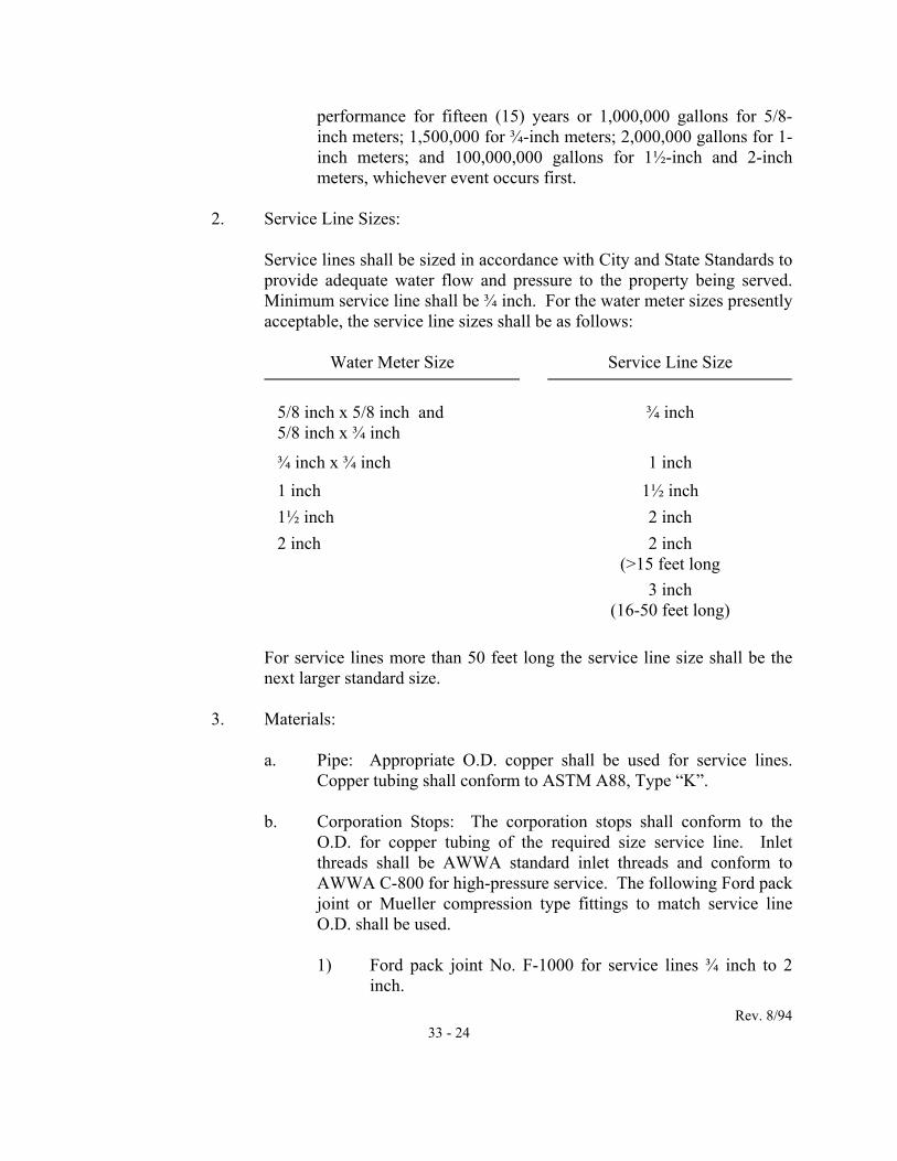
2. Service Line Sizes:
Service lines shall be sized in accordance with City and State Standards to provide adequate water flow and pressure to the property being served. Minimum service line shall be ¾ inch. For the water meter sizes presently acceptable, the service line sizes shall be as follows:
Water Meter Size Service Line Size
5/8 inch x 5/8 inch and 5/8 inch x ¾ inch
¾ inch
¾ inch x ¾ inch 1 inch 1 inch 1½ inch 1½ inch 2 inch 2 inch 2 inch
(>15 feet long 3 inch
(16-50 feet long)
For service lines more than 50 feet long the service line size shall be the next larger standard size.
3. Materials:
a. Pipe: Appropriate O.D. copper shall be used for service lines.
Copper tubing shall conform to ASTM A88, Type “K”. b. Corporation Stops: The corporation stops shall conform to the
O.D. for copper tubing of the required size service line. Inlet threads shall be AWWA standard inlet threads and conform to AWWA C-800 for high-pressure service. The following Ford pack joint or Mueller compression type fittings to match service line O.D. shall be used.
1) Ford pack joint No. F-1000 for service lines ¾ inch to 2
inch.

Rev. 8/94 33 - 25
2) Mueller compression fitting No. H-15008 for service lines
¾ inch to 1 inch; and No. H-15013 for service lines 1½ inch to 2 inch.
c. Angle Curb Stops shall conform to AWWA C-800 for high-
pressure service. The following types shall be used:
1) 5/8” x ¾” x ¾” Ford pack joint No. KV43-332 with ¾” inlet and coupling nut for ¾” meter; or Mueller compression fitting No. H-14253 with ¾” inlet and coupling for ¾” meter.
2) 5/8” x ¾” x 1” Ford pack joint No. KV43-342 with 1” inlet
and coupling for ¾” meter; or Mueller compression fitting No. H-14253 with 1” inlet and coupling for ¾” meter.
d. Angle Flanged Valves shall conform to AWWA C-800 for high-
pressure service. The following types shall be used:
1) 1½” x 1½” x 1½” Ford No. FV43-66w with pack joint inlet; or Mueller compression No. H-14277 with compression inlet to match O.D. of 1½” tubing.
2) 2” x 2” x 1½” and 2” Ford No. FV43-777w with pack joint
inlet; or Mueller No. H-14277 with compression inlet to match O.D. of 2” tubing.
e. Meter Boxes and Vaults:
1) For meter sizes 5/8” to 1” meter boxes shall be Rome Type
MBX1. 2) For meter sizes 1 ½” and 2” meter vaults shall be 18” x 18”
x 36” fabricated with ¼” diamond plate steel in accordance with the typical detail shown in Public Facilities Manual, Volume II.
f. Double strap service saddles must be used for all PVC mains and
on ductile iron mains less than eight (8) inches in diameter for taps 1½” or 2”.
g. Additional materials for 1½” and 2” meters:

Rev. 8/94 33 - 26
1) Required size swing check valve shall conform to AWWA
C-508 and shall be Nibco No. T-413-Y, or approved equal. 2) Required size gate valve shall be bronze T-handle type
Nibco No. T-113-T, or approved equal. Wheel valves will not be accepted.
3) 2” brass adapters shall be MIP Ford pack joint No. C84-77
or MIP Mueller compression No. H-15429 to match O.D. of the pipe.
h. For condominiums, townhouses and duplexes (5/8” x ¾” meter
with a ¾” service line), where feasible a 1” line may be installed and split at the curb, using a ¾” x 1” Y-branch Ford No. Y44-243, ¾” x 1”, or Mueller No. H-15343 ¾” x 1” O.D. tubing.
i. Service Saddles shall conform to AWWA C-800 for high pressure
service:
1) Ductile iron or PVC shall be equal to the Rockwell 313 Double Strop Saddle. Where corrosion protection is necessary, Style 317 (nylon coated) shall be used.
2) Asbestos Cement shall be equal to the Rockwell 331
Saddle.
4. Installation (meter size ⅝” to 2”):
a. The installation of meters shall be in accordance with the detail shown in Public Facilities Manual, Volume II.
b. Meter boxes or vaults shall be placed at the end of each service
line with their tops set at finished grade. For 1½” to 2” meters, all valves and the meter shall be placed inside of the vault.
c. Service lines shall have a minimum of 24” to a maximum of 30”
cover from the top of the tubing to finished grade. The top of the angle curb stop/valve shall be set at an elevation 12” below finished grade.
B. Domestic Meters 3” Size and Larger and Detector Checks: These meters are
classified as large meters. Meters and detector checks shall be delivered to Public

Rev. 8/94 33 - 27
Utilities, 906 Executive Drive, for checking and installation by City forces.
1. Water Meters 3” and larger:
a. Compound, combination or turbine meters manufactured by Hersey or Rockwell shall be used. Contact Public Utilities for a list of specific models approved.
b. Meters must read in cubic feet. c. Compound meters with single registers measuring all flows,
manufactured by Hersey or Rockwell are acceptable.
2. Meter and Service Line Size: Water meter shall be sized in accordance with City and State Standards to provide adequate water flow and pressure to the property to be served. The size of the service feed line shall be one pipe size larger than the meter size. The meter shall be capable of handling the peak domestic flow without exceeding the rated capacity of the meter.
3. Materials: All piping, valves and fittings shall conform to City water
main Standards. 4. Installation:
a. Installation of large meters shall be in accordance with the details shown in Public Facilities Manual, Volume II.
b. Meter vaults shall be metal or concrete as shown on the plans and
shall conform to the details shown in Public Facilities Manual, Volume II.
c. Large meters (3” and above) shall have a bypass of same size as
the meter (except 3” where the bypass shall be 4”). d. All fittings and valves shall be rodded and retained. e. All connections at the water main shall be valved either by a
tapping sleeve and valve or a gate valve in accordance with the City water main standards.
f. No solvent joints shall be used. g. All fittings shall have a minimum of 30” and a maximum of 48”

Rev. 8/94 33 - 28
cover from the finished grade and the top of the vault.
h. The Contractor shall notify Public Utilities (382-3411) at least 48 hours prior to the start of large water meter vault installation.
i. Testing of service pipe and bypass shall be performed in
accordance with Paragraphs 33.03 – P and Q.
C. Closed Fire Service with Detector Check Meters:
1. Water Meters:
a. Detector check meter vault manufactured by Hersey, Mueller, or Viking shall be used.
b. By-pass meter on the detector check shall be of the appropriate size City standard meter and shall be located at the same elevation as the top of the detector check meter.
2. Meter and Service Line Size: The detector check shall be sized in
accordance with City and State Standards to provide adequate flow and pressure to the property to be served. The size of the service feed line shall be one pipe size larger than the meter size.
3. Materials:
a. All piping, valves and fittings shall conform to City Water Main
Standards. b. All fittings for the detector check by-pass meter shall be ¾” brass
and ¾” gate valve and ¾” check valve as shown in the typical detail in Public Facilities Manual, Volume II.
4. Installation:
a. Installation of detector check meter vault shall be in accordance
with the details shown in the Public Facilities Manual, Volume II. b. Meter vaults shall be metal or concrete and shall conform to the
details shown in the Public Facilities Manual, Volume II. c. All connections at the water main shall be valved either by tapping
sleeve and valve or a gate valve in accordance with City Water Main Standards.

Rev. 8/94 33 - 29
d. No solvent joints shall be used. e. All fittings shall have a minimum of 30” and a maximum of 48”
cover from the finished grade and the top of the vault. f. The Contractor shall notify Public Utilities (382-3411) as least 48
hours prior to the start of the meter installation. D. Combination Fire and Domestic Water Meters:
1. Water Meters: MFM-MCT meters measuring in cubic feet manufactured by Hersey or approved equal shall be used.
2. Meter and Service Line Size: The provisions of Paragraph 33.04 B-2 shall
apply. 3. Materials: The provisions of Paragraph 33.04 B-3 shall apply. 4. Installation: The provisions of Paragraph 33.04 B-4 shall apply.
E. Repairs: All water service line repairs shall be made without isolating the water
main. No water valves or corporations shall be closed to make repairs without the prior permission of the Water and Sewer Administrator.
33.05 MEASUREMENT AND PAYMENT:
A. Bid Item Definition:
1. The water main pipe shall include furnishing and installing the pipe, appurtenances, thrust restraints, bedding, excavation sheeting and bracing, dewatering, testing, sampling, disinfection tie-ins, placing in service, backfilling, compaction, and final surface grading. Water main pipes that are 2”, 4”, 6”, 8”, 10” or 12” shall include fittings while pipe greater than 12” shall not include fittings.
2. The water main fittings shall be the furnishing and installation of bends,
tees, sleeves, reducers, retainer glands, caps and plugs with the associated appurtenant bolts, standard gland, and thrust blocking.
3. The valves shall include furnishing and installing each valve and valve
box assembly with the necessary pipe. 4. The fire hydrant assembly shall include the hydrant, the restrained joint

Rev. 8/94 33 - 30
between the valve and hydrant, the thrust restraint, and appurtenant items. This fire hydrant assembly shall not include the valve, the pipe from the main to the valve, or the pipe from the valve to the hydrant.
5. The tapping sleeve and valve shall include the tapping sleeve, the tapping
valve, valve box, and the tapping operation with the necessary appurtenant items.
6. The blow-off at the end of water main piping for flushing shall include the
tapping of the plug or cap, the blow-off piping, valves and restraints, the access box, and the necessary appurtenant items.
7. The air release valve at the high points of the water main piping shall
include the tapping of the pipe, the air release piping, the access box, and the necessary appurtenant items.
8. The offset assembly shall include all necessary pipes, fittings, thrust
restraint and necessary appurtenant items. 9. Water service sizes larger than 2” pipe shall be defined, measured, and
paid for in the same manner as water mains. See the appropriate provisions pertaining to water main pipes, valves, etc., for further information. Vault for large meter and detector checks shall be paid for separately and will include vault, lid, bedding and necessary appurtenant items.
For water services 2” pipe or smaller, the cost for water service
connection shall include service saddle, corporation stop, service line, curb stop and meter box complete in place. On renewal contracts, the cost shall also include reconnection of the Customer’s lines.
B. Measurement and Payment: The term “complete in place” as it is used here, shall
be taken to mean that the item of work shall be furnished and installed in accordance with the specifications complete with all appurtenances necessary for the item to be used for its intended function. Where appropriate, this means that payment for the item includes, but is not necessarily limited to, testing, cleanup, and restoration of all disturbed areas to original condition unless specified otherwise. 1. Water main pipes, which are installed and satisfactorily tested, shall be
measured in place (for each size, class, and type material) in the horizontal plane on the pipe centerline. The measurement for 2”, 4”, 6”, 8”, 10”, and 12” pipe shall include fittings while the measurement for sizes greater than 12” shall exclude fittings. The water main pipe shall be paid for on a linear foot basis.

Rev. 8/94 33 - 31
2. The water main fittings greater than 12”, which are installed and
satisfactorily tested, shall be counted complete in place (for each size, class, and type of fitting) and shall be paid for on a per fitting basis.
3. The valves, which are installed and satisfactorily tested, shall be counted
complete in place (for each size, class, and type of valve) and shall be paid for on a per valve basis.
4. The fire hydrant assemblies, which are installed and satisfactorily tested
shall be counted complete in place and shall be paid for on a per hydrant basis.
5. The tapping sleeve and valves, which are installed and satisfactorily
tested, shall be counted complete in place (for each size, combination of sleeve and valve) and shall be paid for on a per tapping sleeve/valve basis.
6. The blow-offs, air release valves and offsets, which are installed and
satisfactorily tested, shall be counted complete in place and paid for on a per item basis.
7. Water services, which are installed and satisfactorily tested, shall be paid
for on a per service basis. The services shall be counted complete in place for each size service.