division 500 rigid pavement - kansas department of ......division 500 rigid pavement ... pavement is...
TRANSCRIPT

TABLE OF CONTENTS
DIVISION 500 RIGID PAVEMENT
SECTION PAGE
i
501 - PORTLAND CEMENT CONCRETE PAVEMENT (QC/QA) .................................................................. 500-1 502 - PORTLAND CEMENT CONCRETE PAVEMENT (NON-QC/QA) ...................................................... 500-23 503 - PORTLAND CEMENT CONCRETE PAVEMENT SMOOTHNESS ..................................................... 500-37 504 - DOWEL BAR RETROFIT-REPAIR ......................................................................................................... 500-41 505 - TIE BAR INSERTION-REPAIR ............................................................................................................... 500-43

501 - PORTLAND CEMENT CONCRETE PAVEMENT (QC/QA)
500-1
SECTION 501
PORTLAND CEMENT CONCRETE PAVEMENT (QC/QA)
Note: PCCP is considered QC/QA when the bid item Quality Control Testing is included in the contract. Note the exceptions in subsection 501.5.
501.1 DESCRIPTION
Construct Portland Cement Concrete Pavement (PCCP) on a prepared subgrade or base course. Develop and perform quality control testing.
Urban PCCP Environment: Projects or sections of the project classified as Urban Type are typically: within city limits; require pieced construction due to:
business and residential entrances; frequency of side streets; or project phasing.
Before paving, meet with the Engineer to determine if the project or sections of the project are classified as
Urban Type. BID ITEMS UNITS Concrete Pavement (* Uniform) (AE) (**) Square Yard Concrete Pavement (* Variable) (AE) (**) Square Yard Early Strength Concrete Pavement (*Uniform) (AE) (**) Square Yard Early Strength Concrete Pavement (*Variable) (AE) (**) Square Yard
Quality Control Testing (PCCP)+ Square Yard Concrete Core (Set Price) Each * Thickness
** No entry denotes PCCP with mesh and dowel assemblies. "Plain" denotes PCCP without mesh and dowel assemblies. "NRDJ" denotes non-reinforced dowel jointed PCCP. "Br App" denotes bridge approach pavement. + Br App pavement quantities are not included in this item.
501.2 CONTRACTOR QUALITY CONTROL REQUIREMENTS a. General. Provide qualified personnel and sufficient equipment complying with the requirements listed in Part V to conduct quality control testing that complies with Appendix B, Sampling and Testing Frequency Chart for Concrete Construction Items for Quality Control/Quality Assurance Projects. Allow the Engineer access to the Contractor’s laboratory to observe testing procedures, calculations, test documentation and plotting of test results. Calibrate and correlate the testing equipment with prescribed procedures, and conduct tests in compliance with specified testing procedures as listed in Part V.
Maintain a Quality Manual in the field laboratory showing the calibrations performed on all test equipment and when the next calibration is due for that equipment. As a minimum, follow the calibration/verification interval established in Table 1: Concrete Materials Test Equipment in Section 5.2.7.4-Concrete: Contractor’s Quality Control Plan, Part V. See also Section 5.2.7.5-Example of a Laboratory Quality Manual for Concrete, Part V.
b. Quality Control Plan (QCP). At the pre-construction conference, submit to the Engineer for approval
by the DME, a QCP as outlined in Section 5.2.7.4-Concrete: Contractor’s Quality Control Plan, Part V. Follow 5.2.7.4: Concrete: Contractor’s Quality Control Plan in Part V as a general guideline. Keep a printed copy of the approved QCP in the Contractor’s laboratory and make available to the Engineer when requested.
501 - PORTLAND CEMENT CONCRETE PAVEMENT (QC/QA)
500-2
The Contractor’s laboratory and equipment will be inspected and approved as outlined in Section 5.2.7-Contractor’s Quality Control Plan, Part V.
Include a listing of the names and phone numbers of individuals and alternates responsible for quality control administration and inspection. On the Contractor’s organizational chart, show the specified lines of authority relating both to mix design and quality control operations during production. Post the organizational chart in the Contractor’s test facility.
Provide a quality control organization or private testing firm having personnel certified according to the Policy and Procedures Manual for The Certified Inspection and Testing (CIT) Training Program. The testing for this type of construction will require personnel certified in Aggregate Field Tester (AGF), Aggregate Lab Technician (AGL), Profilograph (PO), ACI Concrete Field Testing Technician (CF), Nuclear Moisture Density Gauge Tester (NUC) and Hardened Concrete Properties (HCP) classifications. Provide a minimum of 1 employee on the project certified in the QC/QA Concrete/Cement Treated Base Specs (QCS) classification.
Only persons certified in the appropriate classifications covering the specific tests required shall perform such testing. At the beginning of the project, provide the Engineer with the list of certified technicians and alternates, phone numbers and tests/inspection they will be performing. As personnel changes and certifications may expire, continue to provide the Engineer with an accurate list.
Provide an organizational chart showing the specified lines of authority relating to both mix design and quality control operations during production. Identify the company official acting as liaison with KDOT, and the Certified Technician who will direct inspection and testing. Post the chart in the test facility.
c. Required Duties of Certified Technicians. Be available on the project site whenever concrete for pavement is being produced and being placed on the project site. Perform and utilize quality control tests and other quality control practices to assure that delivered materials and proportioning meet the requirements of the mix designs.
Periodically inspect all equipment utilized in transporting, proportioning, mixing, placing, consolidating, finishing and curing to assure it is operating properly and that placement, consolidation, finishing and curing comply with the mix design and other contract requirements.
d. Contractor’s Testing Facilities. Describe the testing facility and its accreditation in the QCP. Locate the testing facility either at the plant site or at the project. Obtain approval of the testing facilities
and location from the DME before the commencement of mixture production. Provide suitable space for the required testing equipment. Also, equip the testing facility with these items
for the exclusive use of the testing facility’s quality control personnel and the Engineer: A telephone with a private line; A copying machine; and Broadband internet connection (for 1 computer). If the Engineer determines that broadband internet
service is not available, provide a fax machine, at no additional cost.
e. Documentation. Include in the QCP procedures, charts and forms to be used to provide the required documentation.
Record and document all test results and calculations. Record all original documentation in a bound field book or other KDOT approved bound record and turn over to KDOT at the end of the project.
At all times, have complete records of all inspections and tests readily available on site for the Engineer. All records documenting the Contractor’s quality control inspections and tests become the property of KDOT upon completion of the work.
Indicate the nature and number of observations made, the number and type of deficiencies found, the quantities approved and rejected, and the corrective action taken in the records. Examples of quality control forms and charts are available in Part V, or Contractors may design their own. Documentation procedures are subject to approval by the Engineer before the start of the work and to compliance checks during the progress of the work.
Maintain control charts on an ongoing basis. Plot data according to SECTION 106. Record specific test results on a Daily Quality Control Summary sheet designed to facilitate the
computation of moving test averages. Base moving averages on 4 consecutive test results. Include a description of quality control actions taken (such as adjustment of aggregate or additive proportions in the mix, moisture adjustments) in the Daily Quality Control Summary Sheet.
501 - PORTLAND CEMENT CONCRETE PAVEMENT (QC/QA)
500-3
Provide forms on a computer-acceptable medium, where required. Document tickets and gradation data according to KDOT requirements.
Complete testing and charting within 1 working day after sampling. Keep all quality control charts current. Show both individual test results and moving average values. As
a minimum on approved control charts, plot the single test values and the 4 test moving average values for these properties:
Percent air in concrete mixture; Slump of concrete mixture; Concrete unit weight; In-place concrete density on plastic concrete as a percentage of determined unit weight; and Combined aggregate gradation (as a minimum, plot the 3/8" and No. 8 sieves). Also plot the single test values for actual workability and target workability of the combined aggregates. Provide the following test data to the KDOT Project Representative: Copies of all test results and control charts on a weekly basis, representing the prior week’s
production; Copies of the quality control summary sheet on a daily basis. Include, as a minimum, combined
aggregate gradations, actual workability and target workability of combined aggregates, percent air content, slump, concrete unit weight and density of fresh concrete in-place; and
Copies of all failing test results. Include all applicable sieves, actual workability, percent air content, slump and density of fresh concrete in-place.
Copies of vibrator checks daily to the Inspector. Email a weekly recap to the Construction Engineer. Email or fax the data to the Field Engineer and DME, weekly. f. Testing Requirements. In the QCP, identify test methods, procedures and equipment proposed for use.
Use standard KDOT test methods and properly calibrated measuring and testing equipment as outlined in Part V. Detail any alternative sampling method, procedure or inspection equipment proposed to be used. Such alternatives are subject to review and approval by the DME.
Take all samples for tests and perform in-place tests at random locations, selected according to the Contractor’s QC Plan and at the rates specified in the Sampling and Testing Frequency Chart for Portland Cement Concrete Pavement for Quality Control/Quality Assurance Projects in Appendix B, Part V. Retain the latest 10 gradation samples for use by the Engineer.
g. Corrective Action. In the QCP, identify procedures for notifying the Engineer when corrective
measures must be implemented, and for halting production. Notify the Engineer when the moving average test result trend line for any property approaches the
specification limits. Cease operations if 2 consecutive moving average points fall outside the specification limits. Ceasing operations is the Contractor’s responsibility. Quality control tests for this determination include aggregate gradation, compliance with the mix design band, percent air content, concrete unit weight and density of fresh concrete in-place.
Failure to cease operations for the conditions cited above will subject all subsequent material to rejection, or acceptance at a reduced price, as determined by the Engineer.
The Engineer may examine materials represented by individual test results, which lie beyond the Contractor’s normal quality control testing variation. The investigation may be based on either Contractor or KDOT test results. The information from additional testing (including testing of in-place pavement) may be used to define unacceptable work according to SECTION 105. The Engineer will apply appropriate price reductions or initiate corrective action.
If a dispute exists between the Engineer and Contractor about the validity of any test results other than compressive strengths or thickness determination, the KDOT District Materials Laboratory or MRC will perform referee testing. If one of the disputed KDOT test results was generated at the MRC, then an independent laboratory agreeable to both parties will be selected. The AASHTO Accreditation Program shall have approved the selected laboratory for the appropriate test procedure. If referee testing indicates that KDOT test results are correct, the
501 - PORTLAND CEMENT CONCRETE PAVEMENT (QC/QA)
500-4
Contractor is responsible for the cost of additional testing, including referee testing performed at the MRC. If the referee testing indicates that the Contractor test results are correct, KDOT is responsible for the cost of additional testing.
Follow the procedures outlined in subsection 501.5g.(4) if a dispute arises for any test determining compressive strengths or thickness.
h. Non-Conforming Materials. In the QCP, specifically address how non-conforming materials will be
controlled and identified. Establish and maintain an effective and positive system for controlling non-conforming material, including
procedures for its identification, isolation and disposition. Reclaim or rework non-conforming materials according to procedures acceptable to the Engineer.
Identify all non-conforming materials and products to prevent use, shipment and intermingling with conforming materials and products. Provide holding areas, mutually agreeable to the Engineer and Contractor.
i. Concrete Information. Separately list the grades of concrete involved in the project. For each grade of concrete to be used, include at a minimum, the following:
Mix designs. List mix design numbers if using existing mixes. Aggregate production. Quality of components. Stockpile management. Proportioning, including added water. Mixing and transportation. Initial mix properties. Placement and consolidation. Concrete yield. Compressive strength. Finishing and curing. Frequency of sampling and testing. How duties and responsibilities are to be accomplished and documented, and if more than one
Certified Technician is required. The criteria used by the Certified Technician to correct or reject unsatisfactory materials.
501.3 MATERIALS Provide materials that comply with the applicable requirements.
Concrete and Grout ................................................................................. SECTIONS 401& 403 Aggregates for On Grade Concrete ......................................................... SECTION 1116 Reinforcing Steel ..................................................................................... DIVISION 1600 Epoxy Coated Steel Bars for Concrete Reinforcement ........................... DIVISION 1600 Joint Sealants ........................................................................................... DIVISION 1500 Expansion Joint Filler ............................................................................. DIVISION 1500 Concrete Curing Materials ...................................................................... DIVISION 1400 Preformed Elastomeric Compression Joint Seals .................................... DIVISION 1500 Cold Applied Chemically Cured Joint Sealant ........................................ DIVISION 1500 Hot Type Joint Sealing Compound ......................................................... DIVISION 1500 Backer Rod .............................................................................................. DIVISION 1500 Epoxy Resin-Base Bonding System for Concrete ................................... SECTION 1705 Bond Breakers ......................................................................................... SECTION 1718
501.4 CONSTRUCTION REQUIREMENTS a. Preparation of the Subgrade. Before placing any surfacing material on any section, complete the ditches and drains along that section to effectively drain the highway. Trim the base or subgrade to the line, grade
501 - PORTLAND CEMENT CONCRETE PAVEMENT (QC/QA)
500-5
and typical cross-section as shown in the Contract Documents. Maintain the subgrade or base to the as-constructed condition under other bid items, repairing any encountered defects to the specifications of those bid items. Maintain the subgrade surface to readily drain at all times. Protect the subgrade from damage when handling materials, tools and equipment. Do not store or stockpile materials on the subgrade. Do not place material or lay pavement on a frozen or muddy subgrade, or when it is raining or snowing. Lightly spray the subgrade or base with water to obtain a thoroughly moistened condition when the concrete is deposited on it. Do not puddle water on the grade. Do not deposit any material until the subgrade or base has been checked and approved by the Engineer. b. Slip Form Paving. When paving is performed with a slip form paving unit, use equipment as described in subsection 154.5. Pave 24-foot wide mainline pavement in a single operation. Do not exceed 24-foot paving width in a single operation except as follows:
The Contractor may pave a maximum of 2 lanes plus a 6-foot shoulder (30 feet maximum) in a single operation.
For pavements of 3 lanes or more, pave a minimum of 2 lanes mainline (with the option of including a single shoulder for a maximum of 30 feet) in a single operation.
Approval will be based on satisfactory performance of the Contractor’s operation. Place ramps and auxiliary lanes/shoulders as shown in the Contract Documents. Once the paving operation has started, provide adequate equipment and supply of materials to maintain
continuous placement for any given working period. Keep all concrete conveying equipment clean. Do not apply any tractive forces to the slip form paver, except that which is controlled from the machine. Trim to grade the subgrade or surface of the base over which the tracks of the paver will travel. Do not
disturb this surface with other equipment. If the equipment or method of operation requires the subbase to be wider than shown in the Contract Documents, place additional material to provide an adequate surface for the tracks of the paver. Upon completion of the paving operations, remove or repair any base material damaged by the slip form paver’s tracks. All necessary construction and removal of this additional base material is subsidiary to other items of the contract.
Operate the paver continuously, stopping only when absolutely necessary. If the forward motion of the paver is stopped, immediately stop the vibrator and tamping elements.
Deposit the concrete on the grade in successive batches to minimize re-handling. Place concrete over and against any joint assemblies so the joint assembly is retained in its correct position. Spread the concrete using approved mechanical spreaders to prevent segregation and separation of the materials.
After striking the concrete off with the spreader, leave sufficient concrete in place to allow the final shaping by the use of screeds, templates and pans, depending on make, model and type of machines approved for use in the paving train. Adjust the paving units to meet the required final cross-section, minimizing the need to carry back concrete to fill voids or depressions. Adjust each screed or template so a uniform roll of concrete extends the full length of the screed or template and allows just enough concrete to pass under the unit to properly feed the next machine. Do not shove large volumes of concrete with the screed or template. Adjust the screed or template to maintain a uniform cross-section.
Use multiple spreaders for single and multiple lift operations. Place concrete ahead of the initial spreader strikeoff no more than 30 minutes ahead of the final spreader strikeoff.
The use of any paving machine in the paving train is contingent on its ability to finish the pavement satisfactorily to the required grade, section and specified degree of consolidation. The Engineer may at any time require the adjustment, repair or replacement of the machine for unsatisfactory performance.
Correct any edge slump of the pavement in excess of ¼ inch, exclusive of edge rounding, before the concrete hardens. Excessive edge slumping will be sufficient reason to discontinue paving until machinery (or mix) is properly adjusted or removed from the project.
When the machine finishing has been completed, check the surface with a straightedge a minimum of 10 feet in length before texturing. Operate the straightedge parallel to the pavement centerline, starting at the center and progressing outward. Advance in successive stages of less than ½ the length of the straightedge. At the Contractor’s option, this requirement may be eliminated when smoothness is to be determined by the profilograph.
Achieve grade control by use of 1 or more of the following grade reference devices. Approval of any of these devices will be based upon satisfactory performance.
501 - PORTLAND CEMENT CONCRETE PAVEMENT (QC/QA)
500-6
Erected Stringline. Use an erected stringline consisting of a tightly stretched wire or string offset from and parallel to the pavement edge on 1 or both sides. Erect the stringline parallel to the established pavement surface grade and support at intervals as necessary to maintain the established grade and alignment.
Stringless Paving. Control line, grade and pavement cross-section as shown in the Contract Documents. Use electronic guidance systems that meet the requirements and tolerances listed in SECTION 802. Horizontal control is guided by GPS. Vertical control is guided by Total Stations. GPS will not be allowed for Vertical control.
When paving on a fresh subgrade that has not been trimmed by an automatically controlled machine, use an erected stringline or stringless paving to establish grade. When directed by the Engineer, use an erected stringline or stringless paving to match grade control points such as bridges.
c. Placing Reinforcement. Place pavement reinforcement at the locations shown in the Contract
Documents. Use a sufficient number of approved metal, bar supports or pins to hold all dowel bars and tie bars in proper position as required by the Contract Documents. Install tie-bars perpendicular to the concrete face being tied together. Do not use stones, concrete or wood to support the reinforcement.
Joint tie bars may be installed mechanically if approved by the Engineer. The satisfactory placement of the bars depends on the ability of the Contractor’s operation to place and maintain the bars in their true position. When satisfactory placement is not obtained by mechanical means, the Engineer may require the tie bars be installed ahead of placing the concrete, and that they be securely held in their exact position by staking and tying.
Do not install dowel bars mechanically. Install the dowel bars ahead of placing the concrete, and hold them securely in their exact position by staking or tying.
Thoroughly coat each dowel with hard grease or other approved bond breaker as shown in the Contract Documents. The bond breaker coating shall not exceed 15 mils ± 5 mils in thickness when averaged over 3 points measured at the ¼ points on the bar at 90º intervals around the bar.
When reinforced concrete pavement is placed in 2 layers, strike off the entire width of the bottom layer to such length and depth that the sheet of fabric or bar mat may be laid full length on the concrete in its final position without further manipulation. Place the reinforcement directly on the concrete, then place the top layer of concrete, strike it off and screed it. Remove any portion of the bottom layer of concrete that has been placed more than 30 minutes, and replace it with fresh mixed concrete at the Contractor’s expense. When reinforced concrete is placed in 1 layer, the reinforcement may be positioned in advance of the concrete placement or it may be placed in the plastic concrete after initial spreading, by mechanical or vibratory means.
Place the wire mesh reinforcement in the pavement at the locations shown in the Contract Documents. When 2 layers of wire mesh reinforcement are required, support the bottom layer in the required position with bar chairs. Use separators for the top layer if the strike-off can not be used properly for the operation. Lap the reinforcement as shown in the Contract Documents. Laps parallel to the centerline of the pavement are prohibited except for unusual width of pavement lanes or for irregular areas. If the Contract Documents do not show dimensions for laps, the minimum lap either perpendicular or parallel to the centerline of the pavement is 6 inches. Fasten or tie adjacent wire mesh sheets together to hold all parts of the wire mesh sheets in the same plane.
If a “wire pattern” appears on the surface of the fresh pavement, immediately modify placement procedures to eliminate the problem.
Use reinforcing steel free from detrimental materials that could impair the bond between the steel and concrete.
d. Consolidation and Finishing. Perform hand spreading with shovels, not rakes. Do not allow workers
to walk in the fresh concrete with boots or shoes coated with earth or foreign substance. Do not apply moisture to the surface of the concrete pavement unless the Engineer approves the use of
additional water on the fresh concrete surface to lubricate the float of the longitudinal finisher. If unusual weather conditions require the addition of superficial water to the concrete surface, apply it only in the form of a fine, fog mist.
Uniformly consolidate the concrete without voids, and finish to the cross-section and elevation shown in the Contract Documents.
Use vibrators or other approved equipment to consolidate each layer of concrete, when placed in more than 1 lift, or full depth if placed in 1 lift. Uniformly vibrate the concrete across the full width and depth of the pavement so that the density of pavement concrete is a minimum of 98% of the consolidated unit weight. The 98% density
501 - PORTLAND CEMENT CONCRETE PAVEMENT (QC/QA)
500-7
requirement may be eliminated on miscellaneous areas such as entrance pavement, median pavement and gore areas.
Vibrators, either of the surface type (pan or screed) or the immersion type (tube or spud) may be attached to the spreader, paver or finishing machine, or may be mounted on a separate carriage. Only operate the vibrators when the machine they are mounted on is moving forward. Do not operate hand vibrators more than 15 seconds, or less than 5 seconds in any one location unless approved otherwise by the Engineer. Place vibrators in and withdraw from concrete vertically in a slow deliberate manner.
On mainline paving, every 4 hours, check the electronic monitoring system vibrator frequencies with the vibrator under load to comply with the frequencies shown in subsection 154.2e.
If the system indicates a vibrator is not working properly, manually check the vibrators, immediately. If a vibrator is not functioning properly, immediately replace.
If the electronic monitoring system fails to operate properly, manually check the vibrators, immediately. If the vibrators are functioning properly, paving may continue but make all efforts to correct the problem within 3 paving days. The Engineer may allow additional time if circumstances are beyond the Contractor’s control. Perform the vibrator checks manually until the system is fixed.
Document the checks, and give the data to the Inspector, daily. Email a recap of the data to the Engineer, weekly.
Maintain a uniform, continuous roll of concrete over the vibrators ahead of the strike-off. The height of the roll shall be approximately the same height as the thickness of the pavement being vibrated.
In order to obtain concrete consolidation in the vicinity of joint assemblies, the Engineer may require that these areas be hand vibrated with an immersion spud vibrator.
In the event the specified density is not attained, cease paving operations and make necessary adjustments to produce concrete to conform to the density requirements.
Use an approved nuclear density measuring device to monitor in-place density. Provide a moveable bridge and move it to test locations as required to allow the Inspector to work over the fresh concrete.
On projects or areas within projects where the use of conventional equipment is impracticable, other consolidation and finishing equipment may be used with approval of the Engineer.
e. Fixed Form Paving. At the Contractor’s option, the fixed form paving method may be used. (1) Forms. Use straight, metal forms having adequate strength to support the equipment. Each section
shall be a minimum of 10 feet in length. Use forms with a depth equal to the prescribed edge thickness of the concrete, a base width at least equal to the depth of the forms and without a horizontal joint. Use flexible or curved forms of proper radius for curves of 150-foot radius or less, except approved straight forms of 5-foot lengths may be used for curves of a radius from 75 to 150 feet. Flexible or curved forms must be approved by the Engineer. The Engineer may approve the use of wood forms in areas requiring hand finishing. Secure the forms in place to withstand the impact and vibration of the consolidating and finishing equipment without visible spring or settlement. Extend flange braces outward on the base a minimum of ⅔ the height of the form. Remove forms with battered top surfaces or bent, twisted or broken forms. Do not use repaired forms until they have been inspected and approved by the Engineer. Do not use buildup forms, except where the total area of pavement of any specified thickness on the project is less the 2,000 square yards. Do not vary the top face of the form from a true plane more than ⅛ inch in 10 feet, and do not vary the vertical face of the form by more than ¼ inch. The forms shall contain provisions for locking the ends of abutting form sections together tightly, and for secure setting.
(2) Base Support. Provide a foundation under the forms that is compact and true to the specified grade so that the whole length of the form will be set firmly in contact with the grade.
(3) Form Setting. Set forms sufficiently in advance of the point where concrete is being placed so that line and grade may be checked. After the forms have been correctly set, thoroughly tamp the grade mechanically at both the inside and outside edges of the base of the forms. Stake forms into place with a minimum of 3 pins for each 10 feet section. Place a pin at each side of every joint. Tightly lock form sections, free from play or movement in any direction. Do not deviate the form from true line by more than ¼ inch at any point. No excessive settlement or springing of forms under the finishing machine is permitted. Clean and oil forms before the placing of concrete.
(4) Grade and Alignment. Check the alignment and grade elevations of the forms immediately before placing the concrete and make any necessary corrections. When any form has been disturbed or any grade has become unstable, reset and recheck the form.
(5) Placing Reinforcement and Consolidating and Finishing Concrete. Meet the requirements in subsections 501.4c. and d.
501 - PORTLAND CEMENT CONCRETE PAVEMENT (QC/QA)
500-8
(6) Removing Forms. Unless otherwise provided, do not remove forms from freshly placed concrete until it has set for a minimum of 12 hours, except auxiliary forms used temporarily in widened areas. Remove forms carefully to avoid damage to the pavement.
f. Texturing. Use texturing equipment and devices as described in subsection 154.7. Use a burlap drag as soon as all excess moisture has disappeared and while the concrete is still plastic
enough to make a granular surface possible. Following the dragging operation, use a mechanical device to make a final finish or texture by giving the
surface of the plastic pavement a longitudinal tining, unless shown otherwise in the Contract Documents. Perform the operation at such time to minimize displacement of larger aggregate particles and before the surface permanently sets.
Small or irregular areas may be tined by hand methods. On projects of less than 5,000 square yards, or projects with longitudinal tining, the tining and curing
devices may be mounted on the same carriage when approved by the Engineer. Operations of this type will be based on satisfactory performance.
Before final texturing, finish the exposed edge of the pavement to a radius of ¼ inch with an edger. Edge the interior longitudinal joints on multiple-lane pavement to a radius of ⅛ inch. Eliminate any tool marks appearing on the slab adjacent to the joints or edge of the slab. Do not disturb the rounding of the corner of the slab.
g. Joints. (1) General. Construct joints according to the Contract Documents. Failure to construct the joints in the
best possible manner will be cause for suspension of work until the cause of the defective work is remedied. If existing pavement of any type is required to abut with the new pavement, and the termination of the
removal is not at an existing joint, make the new joint by sawing the existing pavement full depth with a diamond saw before removal.
The objective is to create or form a plane of weakness in the fresh concrete before uncontrolled or erratic cracking occurs. The following methods are acceptable:
Use concrete saws to saw all contraction joints no wider than the initial saw cut and to a depth of D/3 ± ¼ inch. Extreme conditions could exist which make it impracticable to prevent erratic cracking by sawing the joints early. At the onset of the project, devise methods, with the approval of the Engineer, to control this cracking.
Make a “plastic concrete cut” straight and well defined so it can be sawed out by the saw crew. The “plastic concrete cut” would replace the specified initial saw cut. Suggested procedures could be the use of a stiff metal parting strip, with or without handles that would be gently inserted in the fresh concrete and removed, thereby parting the interlocking coarse aggregate and providing a plane of weakness.
Cut the fresh concrete with a mason’s trowel and straightedge from a worker’s bridge. It is imperative that the “plastic concrete cut” joint and the second stage saw cut are in the same exact location.
At the Contractor’s option, “early entry” saws may be used based on satisfactory performance and depth of cut recommended by the equipment manufacturer.
Procedures to control erratic cracking are not limited to these examples.
Edge any transverse joint requiring hand finishing and edging with a tool having a radius of ⅛ inch. Do not indent the surface of the pavement with the horizontal face of the edger.
(2) Pressure Relief Joints. Install pressure relief joints according to the bridge approach details in the Contract Documents.
Form or saw openings for the joint material approximately 1 ¾ inches wide for the 2-inch joint and approximately 3 ¾ inches wide for the 4-inch joint at the locations shown in the Contract Documents. Use the lubricant adhesive as recommended by the manufacturer of the pressure relief joint material.
Just before the installation of the joint material, clean the faces of the joint by sandblasting, followed by an air blast to clean all dust from joint faces.
The Engineer may approve pre-positioning of the 2-inch material if adequate means are taken to obtain proper placement and retention, and if deformation of the material does not occur when the fresh concrete is placed against it.

501 - PORTLAND CEMENT CONCRETE PAVEMENT (QC/QA)
500-9
Use a foam spacer block beneath the 4-inch joint filler material to maintain the specified grade. The spacer block is an easily compressed foam material cut to fill the void beneath the joint filler.
(3) Contraction Joints. Install contraction joints of the type, dimensions and spacing shown in the Contract Documents.
Stretch a stringline along the centerline of the joint, or otherwise adequately mark it to verify dowel bar joint assembly alignment.
Install the dowel bar joint assembly so the centerline of the assembly is perpendicular to the centerline of the slab, and the dowels lie parallel to the slab surface and slab centerline. Place concrete so it will not displace or disarrange the joint assembly. Mark the location of contraction joints to assure the joints are sawed in the proper location.
(4) Longitudinal Joints. Construct longitudinal joints according to the Contract Documents. When sawed joints are specified or used, provide approved guide lines or devices to cut the longitudinal joint on the true line as shown in the Contract Documents. Perform the sawing of longitudinal joints at a time that will prevent erratic or uncontrolled cracking. When “plastic concrete cut” methods are used, no sawing or widening of the joint will be required to make a sealant reservoir.
(5) Construction Joints. Make a butt construction joint perpendicular to the centerline of the pavement at the close of each day’s work, or when the process of depositing concrete is stopped for a length of time sufficient for the concrete to take its initial set. Form this joint by using a clean header having a nominal thickness of 2 inches, and minimum cross-sectional area equal to pavement thickness by pavement width. Cut the header true to the crown of the finished pavement. Accurately set and hold it in place in a plane at right angles to centerline and perpendicular to the surface of the pavement.
Protect the top surface of the header with steel. Securely fasten a trapezoidal piece of metal or wood approximately 2 inches wide and a minimum of 1 inch in depth on the face of the header, along the center of the header to form a grooved or keyed joint.
With approval of the Engineer, the Contractor may pave beyond the joint location a distance to maintain the line and grade. Saw the construction joint when the concrete has hardened. Drill holes for reinforcing tie bars and epoxy the bars in-place. Place fresh concrete against the previously placed concrete taking care to avoid injury to the edge. Vibrate the concrete to obtain an interlocking joint and prevent a honeycombed face of the joint. The additional concrete, removal of debris and other work created by this alternative is at the Contractor’s expense.
Unless shown otherwise in the Contract Documents, do not place any construction joint within 5 feet of an expansion, contraction or other construction joint.
(6) Special Joint Construction. Construct special joints as shown in the Contract Documents or as ordered by the Engineer around drainage, utility and other structures located within the concrete pavement boundaries. Hold temporary forms securely in place during the concrete placement operation.
(7) Joint Construction. Construct all joints as shown in the Contract Documents. Repair or replace any curing medium damaged during joint construction. Construct joints as follows:
(a) Induced Plane of Weakness. The first saw cut is a relief cut at the proper joint location, approximately ⅛ inch wide and to the full joint depth as shown in the Contract Documents (D/3 ± ¼ inch). Make the relief cut as soon as the concrete has hardened enough so that no excess raveling or spalling occurs, but before any random cracks develop. The sequence of the relief sawing is at the Contractor’s option, provided all relief sawing is completed before random cracking develops. Use suitable guide lines or devices to cut the joint straight and in the correct location. Repair curing membrane damaged during sawing as directed by the Engineer. See subsection 501.4g.(1) for alternate methods to the first stage sawing. (b) Reservoir Construction. Do not perform widening of the relief joints to full width until the concrete is a minimum of 48 hours old. Delay it longer if the sawing causes raveling of the concrete. If second stage sawing is performed before completion of the curing period, maintain the cure by use of curing tapes, plastic devices or other materials approved by the Engineer. Center the joint groove over the relief cut, and saw it to the dimensions shown in the Contract Documents. Should any spalling of the sawed edges occur that would detrimentally affect the joint seal, patch it with an approved epoxy patching compound and allow it to harden before installing the joint material. Make each patch true to the intended neat lines of the finished cut joint.
(8) Cleaning Joints.
501 - PORTLAND CEMENT CONCRETE PAVEMENT (QC/QA)
500-10
(a) Immediately clean freshly cut sawed joints by flushing with a jet of water under pressure and other necessary tools to remove the resulting slurry from the joint and immediate area. (b) To clean joints, use air compressors equipped with suitable traps capable of removing all surplus water and oil from the compressed air. The Engineer will check the compressed air for contamination, daily. When contaminated air is found to exist, work will be stopped until suitable adjustments are made, and the air stream is found to be free of contaminants. (c) Just before applying the hot or cold joint sealant, complete a final cleaning by air blasting to clean incompressibles from the joint. (d) Before installing preformed elastomeric joint seals, use water or sandblasting equipment to clean the seal reservoir of the transverse joint a minimum of the vertical height of the installed elastomeric joint material plus ½ inch measured from the pavement surface. Use a multiple pass technique until the surfaces are free of dirt, curing compound or any residue that might prevent ready insertion of the seal, or uniform contact with the concrete. (Note: These seals are held in place by compressive forces and friction acting on the faces of the joint, not chemical bonding as with other joint sealants.) After final cleaning, and immediately before installing the seal, blow out the joint seal reservoir with compressed air until it is free of debris and visible water.
(9) Sealing Joints. The joint location, size and configuration is shown in the Contract Documents. Use applicable materials to obtain the required joint sealant configuration. Seal transverse pavement joints with preformed elastomeric compression joint seals, unless shown otherwise in the Contract Documents. Seal longitudinal pavement joints full depth with either a cold applied chemically cured joint sealant or a hot joint sealing compound. Use only 1 type of longitudinal joint sealant on a project, unless otherwise approved by the Engineer. Seal joints before opening to traffic. For opening to construction traffic, see subsection 501.4i.(3)(a).
When using cold applied chemically cured joint sealant, hot joint sealing compound or preformed elastomeric compression joint seals, arrange for a technical representative of the manufacturer to be present during installation of the joint seal to provide guidance on cleaning, preparation of the joint and installation of the seal.
Keep the manufacturer’s technical representative on the project until Contractor and KDOT personnel have been thoroughly trained in the proper installation of the material. The Engineer may waive this requirement for Contractors that are experienced in installing the type and brand of material being used. Provide the Engineer with a résumé of experience for evaluation.
(a) Cold Applied Chemically Cured Joint Sealants. Do not seal joints until they are clean and dry, and the pavement has attained the age recommended by the manufacturer of the sealant. Do not apply sealant to damp concrete, or install it during inclement weather. Do not apply joint sealant when the ambient air temperature is below 40ºF, or as specified by the manufacturer. Place the sealer full depth in close conformity with dimensions shown in the Contract Documents. Any deviation will be cause for rejection of the joint until satisfactory corrective measures are taken.
Apply the joint sealant by an approved mechanical device. Any failure of the joint material in either adhesion or cohesion will be cause for rejection. Repair the joint to the Engineer’s satisfaction.
Some cold applied, chemically cured sealants are not self-leveling and will not position properly in the joint under its own weight. Tool the sealant surface as shown in the Contract Documents. Accomplish tooling before a skin forms on the surface. Do not use soap or oil as a tooling aid.
After a joint has been sealed, promptly remove all surplus joint sealer from the pavement or structure surfaces.
Do not permit traffic over sealed joints until the sealer is tack free, or until debris from traffic can not embed into the sealant. (b) Hot Applied Joint Sealing Compound. Do not seal joints until they are clean and dry, and the pavement has attained the age recommended by the manufacturer of the joint sealing compound. Install joint sealing compound according to the manufacture’s recommendations.
Completely clean out the application unit when changing brands of materials, or if the material exhibits any sign of changes in application characteristics, polymer or oil separation, balling or any signs of jelling. If the application unit contains compatible material from a previous project at start-up, provide the Engineer a certification covering the material in the application unit, including the manufacturer, type, etc. Before start-up, completely clean out any material that can not be identified and certified.

501 - PORTLAND CEMENT CONCRETE PAVEMENT (QC/QA)
500-11
After a joint has been sealed, promptly remove all surplus joint sealer from the pavement or structure surfaces.
Do not permit traffic over sealed joints until the sealer is tack free, or until debris from traffic can not embed into the sealant. (c) Preformed Elastomeric Joint Seals. Concrete that has reached an age that permits proper sawing and cleaning without causing deterioration of the joint edges and joint faces, is considered acceptable for seal installation.
Under normal construction procedures, seal transverse joints full width with no splices made in the preformed joint seal. However, under phased construction of widenings, where the lanes placed earlier have been opened to traffic, the preformed joint seal may be spliced at the construction joint. When the existing seal is peeled back to saw the construction joint, clean it, reapply the lubricant/adhesive and reinstall as soon as possible. After the new seal is installed, place the longitudinal joint sealant through the intersection with the transverse joint, with the transverse seals butted in. Place the longitudinal sealant to encase and seal the ends of the preformed seals.
Install the joint seal with a machine especially designed to compress and install the sealant in an upright position, without cutting, nicking, distorting or otherwise damaging the seal. Apply lubricant to the concrete or the preformed seal (or both), and install the seal in a substantially compressed condition. Place the top of the seal at a depth below the finished surface of the pavement, recommended by the manufacturer.
Use a method of installation such that the joint seal will not be stretched or compressed longitudinally more than 3% of the length, unless stated otherwise in the manufacturer’s instructions. The method of installation will be checked for stretching or compression by comparing the distance between 2 marks on the surface of the seal measured before and after the installation. If the check indicates stretching or compression beyond the limits stated above, modify the method of installation to correct the situation. The Contractor may proceed slightly out of specification for a short distance under the supervision of the manufacturer’s technical representative, while making corrections and adjustments to return to specification limits. This material may remain in place, provided the stretching does not exceed 5%, and the Contractor makes a good faith effort to correct the problem. Once the machine is in proper adjustment and the installation is proceeding satisfactorily, further checks (approximately every 100 joints) will be made to verify proper installation.
Remove any joint seal not conforming to the above stated limits of installation and replace with new material. After being removed for any reason, no seal may be reused.
(10) Sawed (Non-Sealed) Joints. (a) Joint Construction. The joint location, size and configuration are shown in the Contract Documents. Use concrete saws to saw all joints a nominal 1/8 inch wide to the full joint depth, D/3± ¼ inch, unless shown otherwise in the Contract Documents.
Make the saw cut as soon as the concrete has hardened enough so that no excess raveling or spalling occurs, but before any random cracks develop. The sequence of the sawing is at the Contractor’s option, provided all sawing is completed before random cracking develops. Use suitable guide lines or devices to cut the joint straight and in the correct location. (b) Cleaning Joints. Immediately clean freshly cut sawed joints by flushing with a jet of water under pressure and other necessary tools to remove the resulting slurry from the joint and immediate area. Repair curing membrane damaged during sawing and cleaning, as directed by the Engineer. (c) Backer Rod. Install and maintain backer rod (of a size sufficient to prevent debris from entering the joint) in the joint. When major construction traffic is no longer driving on the pavement, and prior to opening to the public, remove the backer rod, and follow with an air blast to remove any debris. (d) Repair of Joints. If the sawed joint is ≥ ¼ inch, seal the joint using Hot Applied Joint Sealing Compound, according to subsections 501.4g.(7) thru (9)(b). Seal transverse joints the full width of pavement. Seal longitudinal joints the full length of the panel. If the joint can not be properly sealed, see subsection 501.4k.
501 - PORTLAND CEMENT CONCRETE PAVEMENT (QC/QA)
500-12
(e) Opening to Traffic. When no joints require sealing, disregard subsection 501.4i.(3)(a), third bullet and 501.4i.(3)(b). (f) Side Roads and Entrance Pavement. If the PCCP is designated with sawed (non-sealed joints), construct the side road and entrance pavement joints according to subsection 501.4g.(10), unless otherwise specified in the Contract Documents. (g) Curb and Gutter/Valley Gutter. Unless specified otherwise in the Contract Documents, if the PCCP is designated with sawed (non-sealed) joints, construct the curb and gutter/valley gutter joints according to subsections 501.4g.(10)(a) thru (c) with the following exception: saw to a depth a minimum of 1 ¼ inches below the surface of the gutter. If the curb and gutter is placed monolithically with the pavement, saw to the same depth as the pavement.
h. Hand Finishing. Hold hand finishing methods to a minimum. Generally, hand methods of placement
and finishing will be permitted as follows: For pavement when a breakdown of some portion of the paving train occurs, making the hand
finishing of that portion of the concrete already in place necessary. For pavement lanes that may be too narrow or a length too short to accommodate a full paving spread. For all irregular shaped areas. For special approach sections to bridges, widened portions at bridges, intersections and sections
widened beyond traffic lanes. When the dimensions of the work make the use of a complete power operated paving impossible, or
impracticable.
For uniform width areas or transition width areas using false forms, finish handwork with a mechanical finishing machine or approved vibrating screed, whenever possible.
Use spud hand vibrators on any area considered impracticable to vibrate with a vibrating screed. Approved metal or wood floats may be used if needed to help close an open or porous surface condition.
Continue the operation of consolidation and screeding or striking off the concrete until the concrete is uniformly consolidated and the surface is true to line, grade and cross-section.
After the pavement has been properly struck off, straightedge the pavement for trueness and finish it. Use a burlap drag to remove surface straightedge marks. The burlap drag may be pulled by hand, but the results shall be similar to that on the mainline pavement.
Manual methods may be used for texturing hand finished pavement areas. Where applicable, the tined texture applies. Use a metal comb with dimensions and spacing shown in subsection 154.7c. Obtain a finished textured surface similar to that produced mechanically.
On miscellaneous areas such as entrance pavement, median pavement and gore areas, texturing with the metal comb may be eliminated. Final finish may be attained by the use of a drag that consists of a seamless strip of damp burlap, cotton fabric or other suitable material capable of producing a uniform surface of gritty texture.
i. Protection and Curing of Concrete. Cure the pavement by using burlap, liquid membrane-forming
compounds, white polyethylene sheeting, concrete curing blankets or reinforced white polyethylene sheeting. Failure to provide proper curing is cause for immediate suspension of the concreting operations.
(1) Burlap, Concrete Curing Blankets, White Polyethylene Sheeting and Reinforced White Polyethylene Sheeting. Place the curing material on the pavement immediately after the pavement has been finished, and the concrete has hardened sufficiently to avoid harmful marring of the surface, yet early enough to prevent undue loss of moisture from the concrete. If the pavement becomes dry before the curing material is placed, moisten the concrete with a fine spray of water. Dampen burlap and place on the surface. Place burlap-polyethylene blankets with the dampened burlap side down. Keep burlap damp throughout the entire curing period.
Lap adjacent units of curing materials approximately 18 inches. Upon removal of the forms, extend the material to completely cover the full depth of the exposed pavement.
Weigh the curing material down using continuous windrows of earth placed along the sides and edges of the pavement and transversely across the pavement on the laps to cause the material to remain in contact with the covered surface throughout the curing period. Other methods may be used with approval of the Engineer.
Walking on the pavement surface to place the curing material is prohibited. Walking on the curing material is prohibited until the pavement has cured sufficiently to prevent damage to the surface.
501 - PORTLAND CEMENT CONCRETE PAVEMENT (QC/QA)
500-13
Leave the curing material in place for a minimum of 4 days, unless otherwise directed by the Engineer. Immediately repair any tears or holes appearing in the material during the curing period, or replace it with material in good condition.
The material may be reused, provided it is kept serviceable by proper repairs, and if in the judgment of Engineer it will provide water retention during the curing period.
(2) Type 2 White Liquid Membrane-Forming Compound. After finishing operations have been completed and immediately after the free water has left the surface, completely coat and seal the surface of the slab with a uniform layer of compound. Apply the compound in 1 application at a minimum rate of 1 gallon per 150 square feet of surface. Thoroughly mix the compound at all times during usage. Do not dilute the compound. Daily provide the Inspector documentation of the quantity of curing compound used.
Protect the treated surface from injury a minimum of 4 days, unless otherwise directed by the Engineer. If the newly coated film is damaged in any way, apply a new coat of material to the affected areas equal in coverage to that specified for the original coat. A minimum of foot traffic will be permitted on the dried film as necessary to properly carry on the work, provided any damage to the film is immediately repaired by application of an additional coat of compound.
Immediately after the forms are removed (fixed form and slip form), coat the entire area of the sides of the slab with compound at the rate specified for the pavement surface, regardless of whether or not further concrete placement will be made against the pavement edge. Approved hand spray equipment will be permitted only for the application of compound on the sides of the slab, for repairing damaged areas and for hand finished areas. Repair any damaged areas caused by joint sawing.
(3) Opening to Traffic. No motorized traffic is allowed on the pavement until all of the following conditions are met.
(a) Construction Traffic Only. The flexural strength of the pavement shall meet or exceed 450 psi. Determine the flexural
strength of the pavement by testing flexural strength specimens utilizing the third point loading method, or by use of a calibrated maturity meter.
If flexural strength does not meet or exceed 450 psi, observe a 10 day curing period before allowing motorized traffic on the pavement. Provide a strength gain curve of concrete cured at 45°F to justify a curing period of less than 10 days.
Provide protection to keep foreign material out of the unsealed joints by an approved method. (b) All Traffic. In addition to subsection 501.4i.(3)(a), seal the joints according to subsection 501.4g.(9).
The Contractor may, at own expense, increase the cement content from the minimum shown in SECTION 403 to accelerate the strength gain of the PCCP.
(4) Cold Weather Curing. Maintain the concrete pavement at a minimum temperature of 40ºF, as measured along the surface of the concrete, for a minimum of 4 days after placing. When the ambient air temperature is expected to drop below 35ºF anytime during the curing period, take precautions to maintain the concrete temperature. Keep a sufficient supply of approved moisture barrier material, other than liquid curing compound, and suitable blanketing material, such as straw, hay and burlap close by. Be prepared to cover the pavement with a moisture barrier and protect all pavement less than 4 days old with blanketing material. Remove, dispose of and replace concrete damaged by cold weather, as determined by the Engineer.
(5) Early Strength Concrete Curing. The curing period shall conform to the requirements specified for regular concrete pavement in subsection 501.4.i. Construct joints according to the manufacturer’s recommendations for early strength concrete pavement.
j. Cold Weather Limitations. If concrete is placed in cold weather, comply with SECTION 401. k. Repair of Defective Pavement Slabs. It is the responsibility of the Contractor to repair any spalled,
cracked or broken panels as specified hereinafter at no cost to KDOT. Completely remove and replace pavement panels (area between contraction joint and contraction joint) containing both transverse and longitudinal cracks (separating the panel into 4 or more parts) through the full depth of the slab.
Properly seal the joints of the repaired or replaced panels. (1) Repair of Spalls.
501 - PORTLAND CEMENT CONCRETE PAVEMENT (QC/QA)
500-14
In no case shall an individual patch of a spall be less than 1 square foot with no dimension less than 1 foot.
For spalls greater than ¼ inch and less than or equal to ½ inch from edge of the original sawed joint, repair with hot pour.
For spalls greater than ½ inch and less than or equal to 1 inch from the edge of the original sawed joint, blast clean and repair with epoxy patch material.
For spalls greater than 1 inch from the edge of original sawed joint, repair by making a saw cut a minimum of 1 inch outside the spalled area to a minimum depth of 2 inches. The interior angles formed by the intersection of adjacent sides of the patch shall be a minimum of 60º. When the spalled area abuts a joint, make the saw cut to a depth of 2 inches or 1/6 the slab thickness, whichever is greater. Chip out the concrete between the saw cut and the joint or primary crack to solid concrete. Do not use chipping hammers greater than 15 pounds. Thoroughly clean all loose material from the formed cavity. Apply a coat of an approved concrete bonding epoxy to the dry, cleaned surface of all sides of the cavity, except the joint. Apply the epoxy by scrubbing the material into the surface with a stiff bristle brush. Place portland cement concrete, epoxy resin concrete or mortar, immediately following application of the epoxy, according to the manufacturer’s recommendations. If the spalled area to be patched abuts a working joint, use an insert or other bond breaking medium during the repair work to maintain working joints. Remove and replace major honeycombed areas found after removal of the forms. Removed areas or sections so removed shall be a minimum of 6 feet in length if less than full width of the lane involved. When it is necessary to remove a section of pavement, also remove and replace any remaining portion of the slab adjacent to the joints that is less than 6 feet in length.
(2) Repair of Cracks in New Reinforced, Dowel Jointed PCCP.
(a) Transverse and Diagonal Cracks. (i) Full Depth. When a single full-depth transverse crack falls within the middle ⅓ of the panel, no
corrective work will be required. Should a second full-depth crack develop within the middle ⅓ of the panel, remove and
replace the panel to the nearest planned contraction joint, eliminating both cracks. If the location of the mid-panel full-depth crack is within 6 feet of the boundaries of the area to be repaired, extend the area to be repaired to include the mid-panel crack.
When any portion of a full-depth crack falls outside the middle ⅓ of the panel, remove and replace the portion of panel between the contraction joint and the crack. Make 1 full-depth saw cut parallel to the contraction joint on the mid-panel side of the crack to be removed. Make another cut in the adjacent panel, parallel to the contraction joint, clear of the basket assembly, but not less than 6 feet from the first cut. Remove the cracked section and basket assembly. Drill holes in both sawed faces, and insert bars to make 2 contraction joints. Use dowels of the same size and spaced the same distance as those shown in the Contract Documents. Drill bar holes ¼ inch ± 0.05 inch larger than the diameter of the bar and fill them with epoxy or grout and insert the new dowel. Support the free ends of the bars parallel to the pavement surface until the epoxy or grout has set, obtaining proper alignment of the bar. Apply grease or an approved bond breaker to the free ends.
If the boundaries of consecutive areas to be repaired are less than 6 feet apart, also remove and replace the areas between the patches.
Saw off the longitudinal joint tie bars at the longitudinal joint. Drill holes midway between the existing bars and insert tie bars to make a new tied longitudinal hinged joint. Use tie bars of the same size and spacing as those in the Contract Documents. Drill bar holes ¼ inch ± 0.05 inch larger than the diameter of the bar and fill them with epoxy or grout and insert new tie bars.
(b) Longitudinal Cracks. When a single longitudinal crack falls within a panel, no corrective work will be required.
501 - PORTLAND CEMENT CONCRETE PAVEMENT (QC/QA)
500-15
When a second full-depth longitudinal crack falls within a panel, remove and replace the panel to the nearest planned contraction joint, eliminating both cracks.
(3) Repair of Cracks in both New Non-reinforced Dowel Jointed PCCP and Mainline Plain PCCP.
(a) Transverse and Diagonal Cracks. (i) Full Depth. If a maximum of 4 panels per any lane mile has a crack, repair according to SECTION
504 - DOWEL BAR RETROFIT-REPAIR, or remove and replace the pavement. If 5 to 18 of the panels per any lane mile has a crack, repair according to SECTION 504
- DOWEL BAR RETROFIT-REPAIR. When 2 consecutive panels have a crack, remove and replace the panels from contraction joint to contraction joint.
If more than 18 of the panels per any lane mile have a crack, remove and replace the pavement bounded by the cracks in that segment. Remove and replace until ¼ mile segment has less than 4 panels cracked, then repair or replace.
(ii) Partial Depth. If coring (at no additional cost to KDOT) verifies the transverse cracks are not full depth, repairs may be made by SECTION 505 - TIE BAR INSERTION-REPAIR. (iii) When required or at the Contractor’s option, remove and replace pavement panels containing any transverse or diagonal crack according to the following: Make a full-depth saw cut in the abutting panel nearest to the crack, parallel to the
contraction joint, just clear of the basket assembly to allow the existing dowel basket assembly to be completely removed. Make a second saw cut parallel with the contraction joint on the opposite side of the crack away from the contraction joint. For plain PCCP, make the saw cut at the joint nearest to the crack. Make the second saw cut opposite the first cut a minimum of 6 feet from the first saw cut to include the crack. Remove the resulting area.
The minimum longitudinal length of a patch is 6 feet. Do not permit a patch to fall within 6 feet of a contraction joint. The maximum distance between doweled/non-doweled contraction joints is 18 feet. Drill holes and insert dowel bars to make new contraction joints within the vertical faces
of both newly created panel ends. Use dowels of the same size and spaced the same distance as shown in the Contract Documents. Drill bar holes ¼ inch ± 0.05 inch larger than the diameter of the bar and fill with epoxy or portland cement grout and insert the new dowel. Support the free ends of the bars until the epoxy or grout has set to obtain proper alignment of the bar. Apply grease or an approved bond breaker to the free ends. Do not use dowel bars in plain PCCP.
Saw off the longitudinal joint tie bars at the longitudinal joint. Drill holes midway between the existing bars and insert tie bars to make a new tied longitudinal hinged joint. Do not place new tie bars within 12 inches of doweled joint. Use tie bars of the same size and spacing as those in the Contract Documents. Drill bar holes ¼ inch ± 0.05 inch larger than the diameter of the bar and fill them with epoxy or grout and insert new tie bars.
(b) Longitudinal Cracks. Repair or remove and replace pavement panels that contain a single longitudinal crack, according to the following:
Repair longitudinal cracks that are within 3 inches of the planned longitudinal joint for their entire length with a partial depth patch as specified for spall in subsection 501.4k.(1), except make the transverse dimension of the patch 6 inches and saw cuts to D/3 ± ¼ inch.
For longitudinal cracks between 3 and 6 inches from the planned longitudinal joint, fill the entire planned longitudinal joint full depth with epoxy through the length of the longitudinal crack.
Repair longitudinal cracks that are 6 inches or more from the planned longitudinal joint by removing and replacing pavement panels, or repair pavement by SECTION 505 - TIE BAR INSERTION-REPAIR.

501 - PORTLAND CEMENT CONCRETE PAVEMENT (QC/QA)
500-16
Remove and replace pavement panels that contain 2 or more longitudinal cracks.
(4) Repair of Cracks in Shoulder Plain PCCP.
(a) Transverse and Diagonal Cracks. When a single transverse crack falls within a panel and is within 3 feet of the transverse
contraction joint, fill the contraction joint according to the Contract Documents and rout and seal the crack.
When 2 or more transverse cracks fall within a panel, remove and replace the panels. (b) Longitudinal Cracks.
When a single longitudinal crack falls within a panel, repair pavement by SECTION 505 - TIE BAR INSERTION-REPAIR.
When 2 or more longitudinal cracks fall within a panel, remove and replace the panels. l. Protection of Pavement from Rain. Before placing PCCP, prepare and submit to the Engineer for
approval, a Protection Plan to address the onset of rain during concrete placement. As a minimum, the plan shall include protective covering and side forms available at the project site at all times to protect the surfaces and edges of the newly placed concrete pavement. Polyethylene, burlap or other covering materials may be used. Side forms may be of wood or steel and shall have a depth a minimum of the thickness of the pavement. Specify the location of the storage site in order that a review of the protective materials may be conducted by the Engineer.
Include the type and amount of protective materials as well as the methods proposed to protect the pavement.
When rain appears imminent, stop all paving operations and initiate the Protection Plan. Extend the covering back to the point where the rain will not indent the surface. Exercise care to prevent unnecessary damage to the surface with the covering.
m. Pavement Smoothness. Evaluate pavement smoothness for pay according to SECTION 503.
501.5 MEASUREMENT AND PAYMENT a. Plan Quantity Measurement. The quantities of concrete pavement for which payment will be made are the quantities shown in the Contract Documents for the traveled way lanes and the various paved approaches, exits and interchanges, provided the project is constructed essentially to details shown in the Contract Documents.
When the Contract Documents have been altered, or when a disagreement exists between the Contractor and the Engineer as to the accuracy of the Contract Document quantities in any location or the entire project, either party has the right to request and cause the quantities involved to be measured according to subsection 501.5b.
b. Measured Quantities. The quantity to be paid for under this item will be the number of square yards of concrete pavement as measured in-place. The width for measurement will be the width of the pavement shown on the typical cross-section of the Contract Documents, additional widening where added, or as otherwise directed in writing by the Engineer. The length will be measured horizontally along the centerline of each roadway or ramp.
c. Excavation Included in Contract. On projects where the grading and the pavement or base
construction is included in the same contract, the Engineer will not measure additional excavation required to obtain the specified subgrade elevation.
d. Sawing and Sealing Joints. The Engineer will not measure this work for separate payment. All costs
of complying with the requirements specified herein are included in the contract price for the concrete pavement in which the joints are located.
e. Quality Control Testing. The Engineer will measure the Contractor’s quality control testing by the square yard of PCCP placed on the project. The Engineer will measure each concrete core when the results from the core information (required for disputed tests) increases payment to the Contractor. All other cores taken as required by this specification are subsidiary to this item.

501 - PORTLAND CEMENT CONCRETE PAVEMENT (QC/QA)
500-17
f. Water. The Engineer will not measure water used in dust control on haul roads, around plant installations, etc.
g. Pavement Thickness and Compressive Strength Determination. (1) General. Make the required corrections for pavement smoothness before making the pavement
thickness determinations. Determination of pavement thickness and pavement compressive strength for the purpose of establishing pay adjustments will be based on test results from cores taken from each lot of pavement.
For mainline pavement, pay adjustments will be made for both thickness and compressive strength. For acceleration lane, deceleration lane, frontage road, side road and ramp pavement, pay adjustments
will be made for thickness, but not compressive strength, unless the Contract Documents specifically require compressive strength pay adjustments.
For gore areas, bridge approach slabs, intersection curb returns, entrances, shoulders, medians and widenings, pay adjustments will not be made for thickness or compressive strength, and pavement cores will not be required.
Where coring is not required, verify that the thickness of the pavement meets or exceeds the Contract
Document requirements by use of stringline, survey or other suitable depth measurement. For pavement types not cored for strength, use only concrete mix designs approved for use in the mainline pavement. The Engineer will observe and document the Contractor’s measurement or other means of ensuring the appropriate thickness of the plastic concrete, and the Engineer will verify that only approved mixes are used. Prior to placing any pavement not specifically defined above, reach an agreement with the Engineer as to the applicability of pay factors.
(2) Lots and Sublots Defined. (a) For mainline and other pavement subject to coring for pay adjustments for both thickness and strength, a lot is defined as the surface area of mainline lane placed in a single day. Normally, divide a lot representing a day’s production into 5 sublots of approximately equal surface area.
For high daily production rates, rates exceeding 6000 square yards per day, the Contractor may choose to divide the day’s production into 2 approximately equal lots consisting of 5 sublots each. Prior to taking any core samples, notify the Engineer of the decision to divide a day’s production into 2 equal lots. For low daily production rates (and not in an urban PCCP environment), the Contractor may choose to divide the lot into a lesser number of sublots as shown in TABLE 501-1. When daily production rates are less than 1000 square yards, and not in an urban PCCP environment, combine the day’s production with the next day’s production to form a lot. When a day’s production involves less than 1000 square yards while completing a particular mix design or project, combine with the previous day’s production and treat as a single lot.
For low daily production rates less than 1000 square yards in an urban PCCP environment, consider each day’s production as a separate lot. KDOT’s representative will core (or have cored) a minimum of two randomly-determined sublots per day; one in the morning and one in the afternoon. Each randomly-determined location will be cored for both strength and thickness, and results inserted into the “Urban PCCP” worksheet for pay adjustment.
TABLE 501-1: PCCP SUBLOT BREAKDOWN
Daily Production Rate in square yards
Number of Sublots
Under 1000 (Urban) 2 1001 – 2000 3 2001 – 4000 4 4001 or more 5
(b) For pavement that is to be cored for thickness only, group each continuous section of acceleration lane, deceleration lane, side road, frontage road and ramp pavement of equal plan thickness and contract unit price into a lot a maximum of 5000 square yards in area. Divide each lot into a minimum of 3 sublots of approximately equal surface area. Sublots shall be a maximum
501 - PORTLAND CEMENT CONCRETE PAVEMENT (QC/QA)
500-18
of 1000 square yards in size. Sample each sublot in a manner so that each square yard of pavement has a chance of being randomly selected for coring.
(3) Coring. The Engineer reserves the right to generate the random locations. If KDOT plans to generate the random locations, the Contractor will be notified before taking cores for thickness determination.
(a) For mainline and other pavement subject to coring for pay adjustments for both thickness and strength, take 1 core sample having a minimum diameter of 4 inches from a randomly selected site within each sublot. The Contractor has the option of taking an additional core sample having a minimum diameter of 2 inches from a randomly selected site within each sublot for the purpose of making an early determination of the pavement thickness only. Select sites according to the approved QCP. Additionally, take 1 companion core having a minimum diameter of 4 inches per each lot at a randomly selected site as designated by the Engineer. Repair all core holes in a manner approved by the Engineer. Perform all coring for the purpose of determining strength a minimum of 21 days after the pavement has been placed, and in time to determine 28-day compressive strengths. Coring prior to the 21-day minimum will be permitted with approval of the Engineer, when opening to early traffic is desired. If the companion cores will be measured and tested by the MRC, the Engineer will deliver the companion cores to the MRC within 25 days after the pavement has been placed. No initial QC compressive strength data will be accepted for concrete paving that is more than 28 days of age, unless approved by the Engineer. (b) For all other PCCP subject to coring for pay adjustment, thickness only, define the lots prior to placement with the Engineer’s approval.
After placement, randomly select each sublot location. Take 1 core sample having a minimum diameter of 2 inches. Repair all core holes in a manner approved by the Engineer. Coring may be performed at any time after all pavement in the lot has been placed.
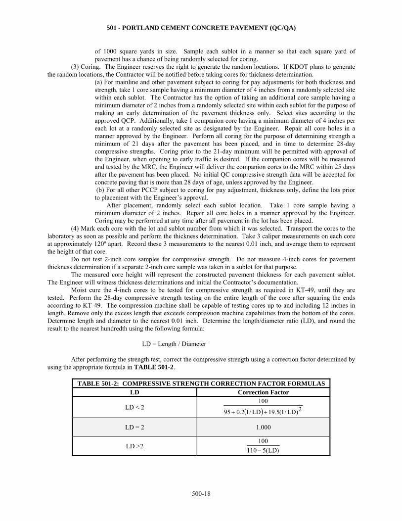
(4) Mark each core with the lot and sublot number from which it was selected. Transport the cores to the laboratory as soon as possible and perform the thickness determination. Take 3 caliper measurements on each core at approximately 120º apart. Record these 3 measurements to the nearest 0.01 inch, and average them to represent the height of that core.
Do not test 2-inch core samples for compressive strength. Do not measure 4-inch cores for pavement thickness determination if a separate 2-inch core sample was taken in a sublot for that purpose.
The measured core height will represent the constructed pavement thickness for each pavement sublot. The Engineer will witness thickness determinations and initial the Contractor’s documentation.
Moist cure the 4-inch cores to be tested for compressive strength as required in KT-49, until they are tested. Perform the 28-day compressive strength testing on the entire length of the core after squaring the ends according to KT-49. The compression machine shall be capable of testing cores up to and including 12 inches in length. Remove only the excess length that exceeds compression machine capabilities from the bottom of the cores. Determine length and diameter to the nearest 0.01 inch. Determine the length/diameter ratio (LD), and round the result to the nearest hundredth using the following formula:
LD = Length / Diameter
After performing the strength test, correct the compressive strength using a correction factor determined by using the appropriate formula in TABLE 501-2.
TABLE 501-2: COMPRESSIVE STRENGTH CORRECTION FACTOR FORMULAS
LD Correction Factor
LD < 2 2)LD/1(5.19LD/12.095
100
LD = 2 1.000
LD >2 )LD(5110
100
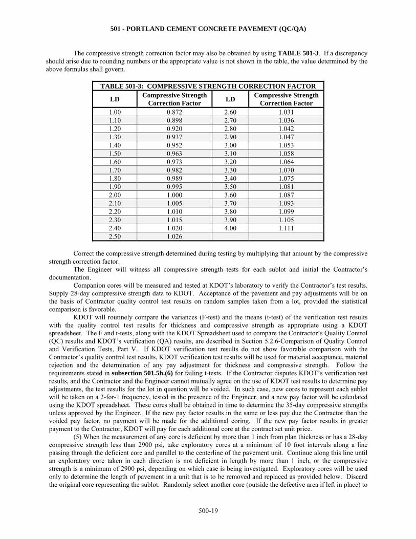
501 - PORTLAND CEMENT CONCRETE PAVEMENT (QC/QA)
500-19
The compressive strength correction factor may also be obtained by using TABLE 501-3. If a discrepancy should arise due to rounding numbers or the appropriate value is not shown in the table, the value determined by the above formulas shall govern.
TABLE 501-3: COMPRESSIVE STRENGTH CORRECTION FACTOR
LD Compressive Strength
Correction Factor LD
Compressive Strength Correction Factor
1.00 0.872 2.60 1.031 1.10 0.898 2.70 1.036 1.20 0.920 2.80 1.042 1.30 0.937 2.90 1.047 1.40 0.952 3.00 1.053 1.50 0.963 3.10 1.058 1.60 0.973 3.20 1.064 1.70 0.982 3.30 1.070 1.80 0.989 3.40 1.075 1.90 0.995 3.50 1.081 2.00 1.000 3.60 1.087 2.10 1.005 3.70 1.093 2.20 1.010 3.80 1.099 2.30 1.015 3.90 1.105 2.40 1.020 4.00 1.111 2.50 1.026
Correct the compressive strength determined during testing by multiplying that amount by the compressive strength correction factor.
The Engineer will witness all compressive strength tests for each sublot and initial the Contractor’s documentation.
Companion cores will be measured and tested at KDOT’s laboratory to verify the Contractor’s test results. Supply 28-day compressive strength data to KDOT. Acceptance of the pavement and pay adjustments will be on the basis of Contractor quality control test results on random samples taken from a lot, provided the statistical comparison is favorable.
KDOT will routinely compare the variances (F-test) and the means (t-test) of the verification test results with the quality control test results for thickness and compressive strength as appropriate using a KDOT spreadsheet. The F and t-tests, along with the KDOT Spreadsheet used to compare the Contractor’s Quality Control (QC) results and KDOT’s verification (QA) results, are described in Section 5.2.6-Comparison of Quality Control and Verification Tests, Part V. If KDOT verification test results do not show favorable comparison with the Contractor’s quality control test results, KDOT verification test results will be used for material acceptance, material rejection and the determination of any pay adjustment for thickness and compressive strength. Follow the requirements stated in subsection 501.5h.(6) for failing t-tests. If the Contractor disputes KDOT’s verification test results, and the Contractor and the Engineer cannot mutually agree on the use of KDOT test results to determine pay adjustments, the test results for the lot in question will be voided. In such case, new cores to represent each sublot will be taken on a 2-for-1 frequency, tested in the presence of the Engineer, and a new pay factor will be calculated using the KDOT spreadsheet. These cores shall be obtained in time to determine the 35-day compressive strengths unless approved by the Engineer. If the new pay factor results in the same or less pay due the Contractor than the voided pay factor, no payment will be made for the additional coring. If the new pay factor results in greater payment to the Contractor, KDOT will pay for each additional core at the contract set unit price. (5) When the measurement of any core is deficient by more than 1 inch from plan thickness or has a 28-day compressive strength less than 2900 psi, take exploratory cores at a minimum of 10 foot intervals along a line passing through the deficient core and parallel to the centerline of the pavement unit. Continue along this line until an exploratory core taken in each direction is not deficient in length by more than 1 inch, or the compressive strength is a minimum of 2900 psi, depending on which case is being investigated. Exploratory cores will be used only to determine the length of pavement in a unit that is to be removed and replaced as provided below. Discard the original core representing the sublot. Randomly select another core (outside the defective area if left in place) to
501 - PORTLAND CEMENT CONCRETE PAVEMENT (QC/QA)
500-20
represent the remainder of the sublot and use to compute the pay factor for the lot. All exploratory cores will be obtained in time to determine the compressive strengths within 35 days from the time the pavement was placed, unless approved by the Engineer. Obtain all cores representing the remainder of the sublot and used to compute the pay factor for the lot in time to determine the 35-day compressive strengths, unless approved by the Engineer. When the Engineer determines that deficient pavement must be removed, the Contractor is required to remove the deficient areas and replace them with pavement of satisfactory quality, strength and thickness. When it is necessary to remove and replace a length of pavement and one end of the deficient pavement is less than 10 feet from an expansion, contraction or construction joint, remove and replace the entire pavement up to the joint. Remove the area so that new joints are a minimum of 10 feet apart. No additional compensation for materials or labor involved in the removal or replacement of the deficient concrete pavement will be made. (6) For sublot thickness results greater than 1 inch more than design thickness, change the sublot thickness result to 1 inch more than the design thickness. The KDOT spreadsheet will calculate a new lot mean and sample standard deviation based on the corrected value. h. Pay Adjustments for Mainline and Other Specified Pavement. (1) General. A single combined pay adjustment for thickness and compressive strength will be made on a lot-by-lot basis and will be based on Contractor quality control test results on all quality control samples representing the lot of the completed pavement provided the statistical check is favorable. Otherwise follow subsection 501.5g.(4). Compute the combined pay factor (P) (positive or negative) as shown in Equation 1. Combined Pay Adjustment = P x (the number of square yards included in the lot) x (the contract unit price
per square yard)
The thickness component of the combined pay factor will be based on values determined by using the difference between plan thickness and the measured core sample thickness, and the lower specification limit (LSL). LSL is defined as 0.2 inch less than plan thickness. The compressive strength component of P will be based on the corrected measured compressive strength of core samples taken from the pavement (see subsection 501.5g.(4) for LD correction). The pay adjustment amount will be added or subtracted as Concrete Pavement Composite Pay Adjustment on the pay estimate.
Note 1: A lot will normally be comprised of the results of 5 tests performed on a day’s placement of a given pavement type. Lot and sublot size is defined in subsection 501.5g.(2).
Note 2: The sample standard deviation (S) will be computed as shown in Section 5.2.1-Statistics, Part V. (2) Thickness Quality Index (QT) Computation. Calculate QT for each lot as shown in 5.2.1, Part V, using the following definitions, and round to hundredths.
Where: X is the average measured core length of all QC samples representing a lot, rounded to the nearest 0.1 inch. LSL is the lower specification limit for thickness, and equals plan thickness minus 0.2 inch. S is the sample standard deviation of the measured core lengths of all QC samples representing a lot, rounded to the nearest hundredth.
(3) Compressive Strength Quality Index (QS) Computation. Calculate QS for each lot as shown in Section
5.2.1-Statistics, Part V, using the following definitions, and round to the nearest 0.1 inch.
Where: X is the average measured compressive strength of all QC core samples representing a lot, rounded to 1 psi. LSL is the lower specification limit for compressive strength and is defined as 3900 psi. S is the sample standard deviation of the compressive strength of all QC samples representing a lot, rounded to the hundredth.
(4) Determination of the Percent within Limits Values. First, use the computed QT to determine the
thickness percent within limits value (PWLT) by locating QT in the left column of the Percent Within Limits (PWL) Table in Section 5.2.1-Statistics, Part V. Select the appropriate (PWLT) by moving across the selected Q row to the
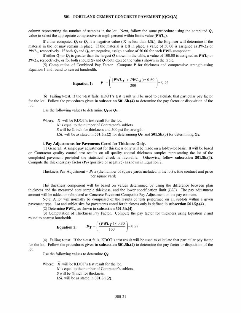
501 - PORTLAND CEMENT CONCRETE PAVEMENT (QC/QA)
500-21
column representing the number of samples in the lot. Next, follow the same procedure using the computed QS value to select the appropriate compressive strength percent within limits value (PWLS).
If either computed QT or QS is a negative value ( X is less than LSL), the Engineer will determine if the material in the lot may remain in place. If the material is left in place, a value of 50.00 is assigned as PWLT or PWLS, respectively. If both QT and QS are negative, assign a value of 50.00 for each PWL component.
If either QT or QS is greater than the largest Q shown in the table, a value of 100.00 is assigned as PWLT or PWLS, respectively, or for both should QT and QS both exceed the values shown in the table.
(5) Computation of Combined Pay Factor. Compute P for thickness and compressive strength using Equation 1 and round to nearest hundredth.
Equation 1: 54.0200
60.0 )(
ST PWLPWL
P
(6) Failing t-test. If the t-test fails, KDOT’s test result will be used to calculate that particular pay factor
for the lot. Follow the procedures given in subsection 501.5h.(4) to determine the pay factor or disposition of the lot.
Use the following values to determine QT or QS :
Where: X will be KDOT’s test result for the lot. N is equal to the number of Contractor’s sublots. S will be ⅜ inch for thickness and 500 psi for strength. LSL will be as stated in 501.5h.(2) for determining QT, and 501.5h.(3) for determining QS.
i. Pay Adjustments for Pavements Cored for Thickness Only.
(1) General. A single pay adjustment for thickness only will be made on a lot-by-lot basis. It will be based on Contractor quality control test results on all quality control thickness samples representing the lot of the completed pavement provided the statistical check is favorable. Otherwise, follow subsection 501.5h.(4). Compute the thickness pay factor (PT) (positive or negative) as shown in Equation 2. Thickness Pay Adjustment = PT x (the number of square yards included in the lot) x (the contract unit price
per square yard)
The thickness component will be based on values determined by using the difference between plan thickness and the measured core sample thickness, and the lower specification limit (LSL). The pay adjustment amount will be added or subtracted as Concrete Pavement Composite Pay Adjustment on the pay estimate.
Note: A lot will normally be comprised of the results of tests performed on all sublots within a given pavement type. Lot and sublot size for pavements cored for thickness only is defined in subsection 501.5g.(4). (2) Determine PWLT as shown in subsection 501.5h.(4).
(3) Computation of Thickness Pay Factor. Compute the pay factor for thickness using Equation 2 and round to nearest hundredth.
Equation 2: 27.0100
30.0 )(
TPWL
PT
(4) Failing t-test. If the t-test fails, KDOT’s test result will be used to calculate that particular pay factor
for the lot. Follow the procedures given in subsection 501.5h.(4) to determine the pay factor or disposition of the lot.
Use the following values to determine QT:
Where: X will be KDOT’s test result for the lot. N is equal to the number of Contractor’s sublots. S will be ⅜ inch for thickness. LSL will be as stated in 501.5 i.(2).

501 - PORTLAND CEMENT CONCRETE PAVEMENT (QC/QA)
500-22
j. Pay Adjustments for Urban PCCP Environment. (1) General. A single pay adjustment will be made on a sublot-by-sublot basis. The adjustment will be
based on a single randomly-selected (by KDOT) core for both strength and thickness. Compute the pay factor (PU) (incentive or disincentive) as shown in Equation 3.
The thickness component will be based on values determined by using the difference between plan thickness and the measured core sample thickness. When the measured core sample thickness is greater than the plan thickness, the “ thickness” of Equation 3 is positive. When the core thickness is less than the plan thickness, the “ thickness” is negative. The compressive strength component will be based on values determined by breaking the core. Pay adjustment amount will be added or subtracted on the pay estimate. Remove and replace when values are less than those stipulated in subsection 501.5g.(5). Maximum individual or combined pay adjustment is 103%.
(2) Computation of Urban PCCP Pay Factor. Compute the pay factor for thickness and strength using Equation 3 and round to nearest hundredth.
Equation 3: PU = (PUC + PUT)/2 Where: PUC = 0.0001*(strength) + 0.59; where strength is measured to the nearest 1 psi.
PUT = 0.15*(∆ thickness) + 1.00; where thickness is measured to the nearest 0.01 inch from plan thickness.
(3) Computation of Urban PCCP Pay Adjustment. Compute the sublot pay adjustment using Equation 4. Equation 4: Urban PCCP Pay Adjustment = (PU – 1)
x (the number of square yards included in the
sublot) x (the contract unit price per square yard) This adjustment will be paid for under the bid item Concrete Pavement Composite Pay Adjustment. k. Computations and Rounding. KDOT will use a MICROSOFT EXCEL spreadsheet program to
calculate pay adjustments for thickness and compressive strength and to compare the Contractor’s QC and KDOT’s verification test results. KDOT will provide a copy of this program to the Contractor, when requested. Additional information on the program may be obtained from the Bureau of Construction and Materials. It is the Contractor’s responsibility to obtain the software required to run this program.
Values computed using equations referenced in this specification may vary slightly from the spreadsheet values due to rounding of numbers. In such cases the numbers computed by the spreadsheet take precedence.
l. General Payment. Payment for "Concrete Pavement", "Early Strength Concrete Pavement" and
"Quality Control Testing" with pay adjustments as specified above is full compensation for the work specified. Payment for "Concrete Core (Set Price)" at the contract set unit price will be paid when the results from the
core information (required for disputed tests) increases payment to the Contractor. In the event of overruns or underruns of the Contractor quality control testing, the Engineer will not adjust the contract unit price.
Pay adjustments for thickness-only and pay adjustments for thickness and strength combined will use the bid item "Concrete Pavement Composite Pay Adjustment", and will be shown as an added item to the contract.
502 - PORTLAND CEMENT CONCRETE PAVEMENT (NON-QC/QA)
500-23
SECTION 502
PORTLAND CEMENT CONCRETE PAVEMENT (NON-QC/QA)
Note: PCCP is considered NON-QC/QA when the bid item Quality Control Testing is not included in the contract.
502.1 DESCRIPTION Construct portland cement concrete pavement (PCCP) on a prepared subgrade or base course. BID ITEMS UNITS Concrete Pavement (* Uniform) (AE) (**) Square Yard
Concrete Pavement (* Variable) (AE) (**) Square Yard Early Strength Concrete Pavement (*Uniform) (AE) (**) Square Yard Early Strength Concrete Pavement (*Variable) (AE) (**) Square Yard
* Thickness ** No entry denotes PCCP with mesh and dowel assemblies. "Plain" denotes PCCP without mesh and dowel assemblies. "NRDJ" denotes non-reinforced dowel jointed PCCP. "Br App" denotes bridge approach pavement.
502.2 MATERIALS Provide materials that comply with the applicable requirements.
Concrete and Grout ................................................................................. SECTIONS 401 & 403 Aggregates for On Grade Concrete ......................................................... SECTION 1116 Reinforcing Steel ..................................................................................... DIVISION 1600 Epoxy Coated Steel Bars for Concrete Reinforcement ........................... DIVISION 1600 Joint Sealants ........................................................................................... DIVISION 1500 Expansion Joint Filler ............................................................................. DIVISION 1500 Concrete Curing Materials ...................................................................... DIVISION 1400 Preformed Elastomeric Compression Joint Seals .................................... DIVISION 1500 Cold Applied Chemically Cured Joint Sealant ........................................ DIVISION 1500 Hot Type Joint Sealing Compound ......................................................... DIVISION 1500 Backer Rod………………………………………………………………DIVISION 1500 Epoxy Resin-Base Bonding System for Concrete ................................... SECTION 1705 Bond Breaker .......................................................................................... SECTION 1718
502.3 CONSTRUCTION REQUIREMENTS a. Preparation of the Subgrade. Before placing any surfacing material on any section, complete the ditches and drains along that section to effectively drain the highway. Trim the base or subgrade to the line, grade and typical cross-section as shown in the Contract Documents. Maintain the subgrade or base to the as-constructed condition under other bid items, repairing any encountered defects to the specifications of those bid items. Maintain the subgrade surface to readily drain at all times. Protect the subgrade from damage when handling materials, tools and equipment. Do not store or stockpile materials on the subgrade. Do not place material or lay pavement on a frozen or muddy subgrade, or when it is raining or snowing. Lightly spray the subgrade or base with water to obtain a thoroughly moistened condition when the concrete is deposited on it. Do not puddle water on the grade. Do not deposit any material until the subgrade or base has been checked and approved by the Engineer.
502 - PORTLAND CEMENT CONCRETE PAVEMENT (NON-QC/QA)
500-24
b. Slip Form Paving. When paving is performed with a slip form paving unit, use equipment as described in subsection 154.5. Pave 24-foot wide mainline pavement in a single operation. Do not exceed 24-foot paving width in a single operation except as follows:
The Contractor may pave a maximum of 2 lanes plus a 6-foot shoulder (30 feet maximum) in a single operation.
For pavements of 3 lanes or more, pave a minimum of 2 lanes mainline (with the option of including a single shoulder for a maximum of 30 feet) in a single operation.
Approval will be based on satisfactory performance of the Contractor’s operation. Place ramps and auxiliary lanes/shoulders as shown in the Contract Documents. Once the paving operation has started, provide adequate equipment and supply of materials to maintain
continuous placement for any given working period. Keep all concrete conveying equipment clean. Do not apply any tractive forces to the slip form paver, except that which is controlled from the machine. Trim to grade the subgrade or surface of the base over which the tracks of the paver will travel. Do not
disturb this surface with other equipment. If the equipment or method of operation requires the subbase to be wider than shown in the Contract Documents, place additional material to provide an adequate surface for the tracks of the paver. Upon completion of the paving operations, remove or repair any base material damaged by the slip form paver’s tracks. All necessary construction and removal of this additional base material is subsidiary to other items of the contract.
Operate the paver continuously, stopping only when absolutely necessary. If the forward motion of the paver is stopped, immediately stop the vibrator and tamping elements.
Deposit the concrete on the grade in successive batches to minimize re-handling. Place concrete over and against any joint assemblies so the joint assembly is retained in its correct position. Spread the concrete using approved mechanical spreaders to prevent segregation and separation of the materials.
After striking the concrete off with the spreader, leave sufficient concrete in place to allow the final shaping by the use of screeds, templates and pans, depending on make, model and type of machines approved for use in the paving train. Adjust the paving units to meet the required final cross-section, minimizing the need to carry back concrete to fill voids or depressions. Adjust each screed or template so a uniform roll of concrete extends the full length of the screed or template and allows just enough concrete to pass under the unit to properly feed the next machine. Do not shove large volumes of concrete with the screed or template. Adjust the screed or template to maintain a uniform cross-section.
Use multiple spreaders for single and multiple lift operations. Place concrete ahead of the initial spreader strikeoff no more than 30 minutes ahead of the final spreader strikeoff.
The use of any paving machine in the paving train is contingent on its ability to finish the pavement satisfactorily to the required grade, section and specified degree of consolidation. The Engineer may at any time require the adjustment, repair or replacement of the machine for unsatisfactory performance.
Correct any edge slump of the pavement in excess of ¼ inch, exclusive of edge rounding, before the concrete hardens. Excessive edge slumping will be sufficient reason to discontinue paving until machinery (or mix) is properly adjusted or removed from the project.
When the machine finishing has been completed, check the surface with a straightedge a minimum of 10 feet in length before texturing. Operate the straightedge parallel to the pavement centerline, starting at the center and progressing outward. Advance in successive stages of less than ½ the length of the straightedge. At the Contractor’s option, this requirement may be eliminated when smoothness is to be determined by the profilograph.
c. Placing Reinforcement. Place pavement reinforcement at the locations shown in the Contract
Documents. Use a sufficient number of approved metal, bar supports or pins to hold all dowel bars and tie bars in proper position as required by the Contract Documents. Install tie bars perpendicular to the concrete face being tied together. Do not use stones, concrete or wood to support the reinforcement.
Joint tie bars may be installed mechanically if approved by the Engineer. The satisfactory placement of the bars depends on the ability of the Contractor’s operation to place and maintain the bars in their true position. When satisfactory placement is not obtained by mechanical means, the Engineer may require the tie bars be installed ahead of placing the concrete, and that they be securely held in their exact position by staking and tying.
Do not install dowel bars mechanically. Install the dowel bars ahead of placing the concrete, and hold them securely in their exact position by staking or tying.
502 - PORTLAND CEMENT CONCRETE PAVEMENT (NON-QC/QA)
500-25
Thoroughly coat each dowel with hard grease or other approved bond breaker as shown in the Contract Documents. The bond breaker coating shall not exceed 15 mils ± 5 mils in thickness when averaged over 3 points measured at the ¼ points on the bar at 90º intervals around the bar.
When reinforced concrete pavement is placed in 2 layers, strike off the entire width of the bottom layer to such length and depth that the sheet of fabric or bar mat may be laid full length on the concrete in its final position without further manipulation. Place the reinforcement directly on the concrete, then place the top layer of concrete, strike it off and screed it. Remove any portion of the bottom layer of concrete that has been placed more than 30 minutes, and replace it with fresh mixed concrete at the Contractor’s expense. When reinforced concrete is placed in 1 layer, the reinforcement may be positioned in advance of the concrete placement or it may be placed in the plastic concrete after initial spreading, by mechanical or vibratory means.
Place the wire mesh reinforcement in the pavement at the locations shown in the Contract Documents. When 2 layers of wire mesh reinforcement are required, support the bottom layer in the required position with bar chairs. Use separators for the top layer if the strike-off can not be used properly for the operation. Lap the reinforcement as shown in the Contract Documents. Laps parallel to the centerline of the pavement are prohibited except for unusual width of pavement lanes or for irregular areas. If the Contract Documents do not show dimensions for laps, the minimum lap either perpendicular or parallel to the centerline of the pavement is 6 inches. Fasten or tie adjacent wire mesh sheets together to hold all parts of the wire mesh sheets in the same plane.
If a “wire pattern” appears on the surface of the fresh pavement, immediately modify placement procedures to eliminate the problem.
Use reinforcing steel free from detrimental materials that could impair the bond between the steel and concrete.
d. Consolidation and Finishing. Perform hand spreading with shovels, not rakes. Do not allow workers
to walk in the fresh concrete with boots or shoes coated with earth or foreign substance. Do not apply moisture to the surface of the concrete pavement unless the Engineer approves the use of
additional water on the fresh concrete surface to lubricate the float of the longitudinal finisher. If unusual weather conditions require the addition of superficial water to the concrete surface, apply it only in the form of a fine, fog mist.
Uniformly consolidate the concrete without voids, and finish to the cross-section and elevation shown in the Contract Documents.
Use vibrators or other approved equipment to consolidate each layer of concrete, when placed in more than 1 lift, or full depth if placed in 1 lift. Uniformly vibrate the concrete across the full width and depth of the pavement so that the density of pavement concrete is a minimum of 98% of the vibrated unit weight. The 98% density requirement may be eliminated on miscellaneous areas such as entrance pavement, median pavement and gore areas.
Vibrators, either of the surface type (pan or screed) or the immersion type (tube or spud) may be attached to the spreader, paver or finishing machine, or may be mounted on a separate carriage. Only operate the vibrators when the machine they are mounted on is moving forward. Do not operate hand vibrators more than 15 seconds, or less than 5 seconds in any one location unless approved otherwise by the Engineer. Place vibrators in and withdraw from concrete vertically in a slow deliberate manner.
On mainline paving, every 4 hours, check the electronic monitoring system vibrator frequencies with the vibrator under load to comply with the frequencies shown in subsection 154.2e.
If the system indicates a vibrator is not working properly, manually check the vibrators, immediately. If a vibrator is not functioning properly, immediately replace.
If the electronic monitoring system fails to operate properly, manually check the vibrators, immediately. If the vibrators are functioning properly, paving may continue but make all efforts to correct the problem within 3 paving days. The Engineer may allow additional time if circumstances are beyond the Contractor’s control. Perform the vibrator checks manually until the system is fixed.
Maintain a uniform, continuous roll of concrete over the vibrators ahead of the strike-off. The height of the roll shall be approximately the same height as the thickness of the pavement being vibrated.
In order to obtain concrete consolidation in the vicinity of joint assemblies, the Engineer may require that these areas be hand vibrated with an immersion spud vibrator.
In the event the specified density is not attained, cease paving operations and make necessary adjustments to produce concrete to conform to the density requirements.
502 - PORTLAND CEMENT CONCRETE PAVEMENT (NON-QC/QA)
500-26
Use an approved nuclear density measuring device to monitor in-place density. Provide a moveable bridge and move it to test locations as required to allow the Inspector to work over the fresh concrete.
On projects or areas within projects where the use of conventional equipment is impracticable, other consolidation and finishing equipment may be used with approval of the Engineer.
e. Fixed Form Paving. At the Contractor’s option, the fixed form paving method may be used. (1) Forms. Use straight, metal forms having adequate strength to support the equipment. Each section
shall be a minimum of 10 feet in length. Use forms with a depth equal to the prescribed edge thickness of the concrete, a base width at least equal to the depth of the forms and without a horizontal joint. Use flexible or curved forms of proper radius for curves of 150-foot radius or less, except approved straight forms of 5-foot lengths may be used for curves of a radius from 75 to 150 feet. Flexible or curved forms must be approved by the Engineer. The Engineer may approve the use of wood forms in areas requiring hand finishing. Secure the forms in place to withstand the impact and vibration of the consolidating and finishing equipment without visible spring or settlement. Extend flange braces outward on the base a minimum of ⅔ the height of the form. Remove forms with battered top surfaces or bent, twisted or broken forms. Do not use repaired forms until they have been inspected and approved by the Engineer. Do not use buildup forms, except where the total area of pavement of any specified thickness on the project is less the 2,000 square yards. Do not vary the top face of the form from a true plane more than ⅛ inch in 10 feet, and do not vary the vertical face of the form by more than ¼ inch. The forms shall contain provisions for locking the ends of abutting form sections together tightly, and for secure setting.
(2) Base Support. Provide a foundation under the forms that is compact and true to the specified grade so that the whole length of the form will be set firmly in contact with the grade.
(3) Form Setting. Set forms sufficiently in advance of the point where concrete is being placed so that line and grade may be checked. After the forms have been correctly set, thoroughly tamp the grade mechanically at both the inside and outside edges of the base of the forms. Stake forms into place with a minimum of 3 pins for each 10-foot section. Place a pin at each side of every joint. Tightly lock form sections, free from play or movement in any direction. Do not deviate the form from true line by more than ¼ inch at any point. No excessive settlement or springing of forms under the finishing machine is permitted. Clean and oil forms before the placing of concrete.
(4) Grade and Alignment. Check the alignment and grade elevations of the forms immediately before placing the concrete and make any necessary corrections. When any form has been disturbed or any grade has become unstable, reset and recheck the form.
(5) Placing Reinforcement and Consolidating and Finishing Concrete. Meet the requirements in subsections 502.3 c. and d.
(6) Removing Forms. Unless otherwise provided, do not remove forms from freshly placed concrete until it has set for a minimum of 12 hours, except auxiliary forms used temporarily in widened areas. Remove forms carefully to avoid damage to the pavement.
f. Texturing. Use texturing equipment and devices as described in subsection 154.7. Use a burlap drag as soon as all excess moisture has disappeared and while the concrete is still plastic
enough to make a granular surface possible. Following the dragging operation, use a mechanical device to make a final finish or texture by giving the
surface of the plastic pavement a longitudinal tining, unless shown otherwise in the Contract Documents. Perform the operation at such time to minimize displacement of larger aggregate particles and before the surface permanently sets.
Small or irregular areas may be tined by hand methods. On projects of less than 5,000 square yards, or projects with longitudinal tining, the tining and curing
devices may be mounted on the same carriage when approved by the Engineer. Operations of this type will be based on satisfactory performance.
Before final texturing, finish the exposed edge of the pavement to a radius of ¼ inch with an edger. Edge the interior longitudinal joints on multiple-lane pavement to a radius of ⅛ inch. Eliminate any tool marks appearing on the slab adjacent to the joints or edge of the slab. Do not disturb the rounding of the corner of the slab.
g. Joints. (1) General. Construct joints according to the Contract Documents. Failure to construct the joints in the
best possible manner will be cause for suspension of work until the cause of the defective work is remedied.
502 - PORTLAND CEMENT CONCRETE PAVEMENT (NON-QC/QA)
500-27
If existing pavement of any type is required to abut with the new pavement, and the termination of the removal is not at an existing joint, make the new joint by sawing the existing pavement full depth with a diamond saw before removal.
The objective is to create or form a plane of weakness in the fresh concrete before uncontrolled or erratic cracking occurs. The following methods are acceptable:
Use concrete saws to saw all contraction joints no wider than the initial saw cut and to a depth of D/3 ± ¼ inch. Extreme conditions could exist which make it impracticable to prevent erratic cracking by sawing the joints early. At the onset of the project, devise methods, with the approval of the Engineer, to control this cracking.
Make a “plastic concrete cut” straight and well defined so it can be sawed out by the saw crew. The “plastic concrete cut” would replace the specified initial saw cut. Suggested procedures could be the use of a stiff metal parting strip, with or without handles that would be gently inserted in the fresh concrete and removed, thereby parting the interlocking coarse aggregate and providing a plane of weakness.
Cut the fresh concrete with a mason’s trowel and straightedge from a worker’s bridge. It is imperative that the “plastic concrete cut” joint and the second stage saw cut are in the same exact location.
At the Contractor’s option, “early entry” saws may be used based on satisfactory performance and depth of cut recommended by the equipment manufacturer.
Procedures to control erratic cracking are not limited to these examples. Edge any transverse joint requiring hand finishing and edging with a tool having a radius of ⅛ inch. Do not indent the surface of the pavement with the horizontal face of the edger.
(2) Pressure Relief Joints. Install pressure relief joints according to the bridge approach details in the Contract Documents.
Form or saw openings for the joint material approximately 1 ¾ inches wide for the 2 inch joint and approximately 3 ¾ inches wide for the 4 inch joint at the locations shown in the Contract Documents. Use the lubricant adhesive as recommended by the manufacturer of the pressure relief joint material.
Just before the installation of the joint material, clean the faces of the joint by sandblasting, followed by an air blast to clean all dust from joint faces.
The Engineer may approve pre-positioning of the 2 inch material if adequate means are taken to obtain proper placement and retention, and if deformation of the material does not occur when the fresh concrete is placed against it.
Use a foam spacer block beneath the 4 inch joint filler material to maintain the specified grade. The spacer block is an easily compressed foam material cut to fill the void beneath the joint filler.
(3) Contraction Joints. Install contraction joints of the type, dimensions and spacing shown in the Contract Documents.
Stretch a stringline along the centerline of the joint, or otherwise adequately mark it to verify dowel bar joint assembly alignment.
Install the dowel bar joint assembly so the centerline of the assembly is perpendicular to the centerline of the slab, and the dowels lie parallel to the slab surface and slab centerline. Place concrete so it will not displace or disarrange the joint assembly. Mark the location of contraction joints to assure the joints are sawed in the proper location.
(4) Longitudinal Joints. Construct longitudinal joints according to the Contract Documents. When sawed joints are specified or used, provide approved guide lines or devices to cut the longitudinal joint on the true line as shown in the Contract Documents. Perform the sawing of longitudinal joints at a time that will prevent erratic or uncontrolled cracking. When “plastic concrete cut” methods are used, no sawing or widening of the joint will be required to make a sealant reservoir.
(5) Construction Joints. Make a butt construction joint perpendicular to the centerline of the pavement at the close of each day’s work, or when the process of depositing concrete is stopped for a length of time sufficient for the concrete to take its initial set. Form this joint by using a clean header having a nominal thickness of 2 inches, and minimum cross-sectional area equal to pavement thickness by pavement width. Cut the header true to the crown of the finished pavement. Accurately set and hold it in place in a plane at right angles to centerline and perpendicular to the surface of the pavement.

502 - PORTLAND CEMENT CONCRETE PAVEMENT (NON-QC/QA)
500-28
Protect the top surface of the header with steel. Securely fasten a trapezoidal piece of metal or wood approximately 2 inches wide and a minimum of 1 inch in depth on the face of the header, along the center of the header to form a grooved or keyed joint.
With approval of the Engineer, the Contractor may pave beyond the joint location a distance to maintain the line and grade. Saw the construction joint when the concrete has hardened. Drill holes for reinforcing tie bars and epoxy the bars in-place. Place fresh concrete against the previously placed concrete taking care to avoid injury to the edge. Vibrate the concrete to obtain an interlocking joint and prevent a honeycombed face of the joint. The additional concrete, removal of debris and other work created by this alternative is at the Contractor’s expense.
Unless shown otherwise in the Contract Documents, do not place any construction joint within 5 feet of an expansion, contraction or other construction joint.
(6) Special Joint Construction. Construct special joints as shown in the Contract Documents or as ordered by the Engineer around drainage, utility and other structures located within the concrete pavement boundaries. Hold temporary forms securely in place during the concrete placement operation.
(7) Joint Construction. Construct all joints as shown in the Contract Documents. Repair or replace any curing medium damaged during joint construction. Construct joints as follows:
(a) Induced Plane of Weakness. The first saw cut is a relief cut at the proper joint location, approximately ⅛ inch wide and to the full joint depth as shown in the Contract Documents (D/3 ± ¼ inch). Make the relief cut as soon as the concrete has hardened enough so that no excess raveling or spalling occurs, but before any random cracks develop. The sequence of the relief sawing is at the Contractor’s option, provided all relief sawing is completed before random cracking develops. Use suitable guide lines or devices to cut the joint straight and in the correct location. Repair curing membrane damaged during sawing as directed by the Engineer. See subsection 502.3g.(1) for alternate methods to the first stage sawing. (b) Reservoir Construction. Do not perform widening of the relief joints to full width until the concrete is a minimum of 48 hours old. Delay it longer if the sawing causes raveling of the concrete. If second stage sawing is performed before completion of the curing period, maintain the cure by use of curing tapes, plastic devices or other materials approved by the Engineer. Center the joint groove over the relief cut, and saw it to the dimensions shown in the Contract Documents. Should any spalling of the sawed edges occur that would detrimentally affect the joint seal, patch it with an approved epoxy patching compound and allow it to harden before installing the joint material. Make each patch true to the intended neat lines of the finished cut joint.
(8) Cleaning Joints. (a) Immediately clean freshly cut sawed joints by flushing with a jet of water under pressure and other necessary tools to remove the resulting slurry from the joint and immediate area. (b) To clean the joints, use air compressors equipped with suitable traps capable of removing all surplus water and oil from the compressed air. The Engineer will check the compressed air for contamination, daily. When contaminated air is found to exist, work will be stopped until suitable adjustments are made, and the air stream is found to be free of contaminants. (c) Just before applying the hot or cold joint sealant, complete a final cleaning by air blasting to clean incompressibles from the joint. (d) Before installing preformed elastomeric joint seals, use water or sandblasting equipment to clean the seal reservoir of the transverse joint a minimum of the vertical height of the installed elastomeric joint material plus ½ inch measured from the pavement surface. Use a multiple pass technique until the surfaces are free of dirt, curing compound or any residue that might prevent ready insertion of the seal, or uniform contact with the concrete. (Note: These seals are held in place by compressive forces and friction acting on the faces of the joint, not chemical bonding as with other joint sealants.) After final cleaning, and immediately before installing the seal, blow out the joint seal reservoir with compressed air until it is free of debris and visible water.
(9) Sealing Joints. The joint location, size and configuration is shown in the Contract Documents. Use applicable materials to obtain the required joint sealant configuration. Seal transverse pavement joints with preformed elastomeric compression joint seals, unless shown otherwise in the Contract Documents. Seal longitudinal pavement joints full depth with either a cold applied chemically cured joint sealant or a hot joint sealing compound. Use only 1 type of longitudinal joint sealant on a project, unless otherwise approved by the Engineer. Seal joints before opening to traffic. For opening to construction traffic, see subsection 502.3i.(3)(a).
502 - PORTLAND CEMENT CONCRETE PAVEMENT (NON-QC/QA)
500-29
When using cold applied chemically cured joint sealant, hot joint sealing compound or preformed elastomeric compression joint seals, arrange for a technical representative of the manufacturer to be present during installation of the joint seal to provide guidance on cleaning, preparation of the joint and installation of the seal.
Keep the manufacturer’s technical representative on the project until Contractor and KDOT personnel have been thoroughly trained in the proper installation of the material. The Engineer may waive this requirement for Contractors that are experienced in installing the type and brand of material being used. Provide the Engineer with a résumé of experience for evaluation.
(a) Cold Applied Chemically Cured Joint Sealants. Do not seal joints until they are clean and dry, and the pavement has attained the age recommended by the manufacturer of the sealant. Do not apply sealant to damp concrete, or install it during inclement weather. Do not apply joint sealant when the ambient air temperature is below 40ºF, or as specified by the manufacturer. Place the sealer full depth in close conformity with dimensions shown in the Contract Documents. Any deviation will be cause for rejection of the joint until satisfactory corrective measures are taken.
Apply the joint sealant by an approved mechanical device. Any failure of the joint material in either adhesion or cohesion will be cause for rejection. Repair the joint to the Engineer’s satisfaction.
Some cold applied, chemically cured sealants are not self-leveling and will not position properly in the joint under its own weight. Tool the sealant surface as shown in the Contract Documents. Accomplish tooling before a skin forms on the surface. Do not use soap or oil as a tooling aid.
After a joint has been sealed, promptly remove all surplus joint sealer from the pavement or structure surfaces.
Do not permit traffic over sealed joints until the sealer is tack free, or until debris from traffic can not embed into the sealant. (b) Hot Applied Joint Sealing Compound. Do not seal joints until they are clean and dry, and the pavement has attained the age recommended by the manufacturer of the joint sealing compound. Install joint sealing compound according to the manufacture’s recommendations.
Completely clean out the application unit when changing brands of materials, or if the material exhibits any sign of changes in application characteristics, polymer or oil separation, balling or any signs of jelling. If the application unit contains compatible material from a previous project at start-up, provide the Engineer a certification covering the material in the application unit, including the manufacturer, type, etc. Before start-up completely clean out any material that can not be identified and certified.
After a joint has been sealed, promptly remove all surplus joint sealer from the pavement or structure surfaces.
Do not permit traffic over sealed joints until the sealer is tack free, or until debris from traffic can not embed into the sealant. (c) Preformed Elastomeric Joint Seals. Concrete that has reached an age that permits proper sawing and cleaning without causing deterioration of the joint edges and joint faces, is considered acceptable for seal installation.
Under normal construction procedures, seal transverse joints full width with no splices made in the preformed joint seal. However, under phased construction of widenings, where the lanes placed earlier have been opened to traffic, the preformed joint seal may be spliced at the construction joint. When the existing seal is peeled back to saw the construction joint, clean it, reapply the lubricant/adhesive and reinstall as soon as possible. After the new seal is installed, place the longitudinal joint sealant through the intersection with the transverse joint, with the transverse seals butted in. Place the longitudinal sealant to encase and seal the ends of the preformed seals.
Install the joint seal with a machine especially designed to compress and install the sealant in an upright position, without cutting, nicking, distorting or otherwise damaging the seal. Apply lubricant to the concrete or the preformed seal (or both), and install the seal in a substantially compressed condition. Place the top of the seal at a depth below the finished surface of the pavement recommended by the manufacturer.
Use a method of installation such that the joint seal will not be stretched or compressed longitudinally more than 3% of the length, unless stated otherwise in the manufacturer’s
502 - PORTLAND CEMENT CONCRETE PAVEMENT (NON-QC/QA)
500-30
instructions. The method of installation will be checked for stretching or compression by comparing the distance between 2 marks on the surface of the seal measured before and after the installation. If the check indicates stretching or compression beyond the limits stated above, modify the method of installation to correct the situation. The Contractor may proceed slightly out of specification for a short distance under the supervision of the manufacturer’s technical representative, while making corrections and adjustments to return to specification limits. This material may remain in place, provided the stretching does not exceed 5% and the Contractor makes a good faith effort to correct the problem. Once the machine is in proper adjustment and the installation is proceeding satisfactorily, further checks (approximately every 100 joints) will be made to verify proper installation.
Remove any joint seal not conforming to the above stated limits of installation and replace with new material. After being removed for any reason, no seal may be reused.
(10) Sawed (Non-Sealed) Joints. (a) Joint Construction. The joint location, size and configuration are shown in the Contract Documents. Use concrete saws to saw all joints a nominal 1/8 inch wide to the full joint depth, D/3± ¼ inch, unless shown otherwise in the Contract Documents.
Make the saw cut as soon as the concrete has hardened enough so that no excess raveling or spalling occurs, but before any random cracks develop. The sequence of the sawing is at the Contractor’s option, provided all sawing is completed before random cracking develops. Use suitable guide lines or devices to cut the joint straight and in the correct location. (b) Cleaning Joints. Immediately clean freshly cut sawed joints by flushing with a jet of water under pressure and other necessary tools to remove the resulting slurry from the joint and immediate area. Repair curing membrane damaged during sawing and cleaning, as directed by the Engineer. (c) Backer Rod. Install and maintain backer rod (of a size sufficient to prevent debris from entering the joint) in the joint. When major construction traffic is no longer driving on the pavement, and prior to opening to the public, remove the backer rod, and follow with an air blast to remove any debris. (d) Repair of Joints. If the sawed joint is ≥ ¼ inch, seal the joint using Hot Applied Joint Sealing Compound, according to subsections 502.4g.(7) thru (9)(b). Seal transverse joints the full width of pavement. Seal longitudinal joints the full length of the panel. If the joint can not be properly sealed, see subsection 502.4k. (e) Opening to Traffic. When no joints require sealing, disregard subsection 502.4i.(3)(a), third bullet and 502.4i.(3)(b). (f) Side Roads and Entrance Pavement. If the PCCP is designated with sawed (non-sealed joints), construct the side road and entrance pavement joints according to subsection 502.4g.(10), unless otherwise specified in the Contract Documents. (g) Curb and Gutter/Valley Gutter. Unless specified otherwise in the Contract Documents, if the PCCP is designated with sawed (non-sealed) joints, construct the curb and gutter/valley gutter joints according to subsections 502.4g.(10)(a) thru (c) with the following exception: saw to a depth a minimum of 1 ¼ inches below the surface of the gutter. If the curb and gutter is placed monolithically with the pavement, saw to the same depth as the pavement.
h. Hand Finishing. Hold hand finishing methods to a minimum. Generally, hand methods of placement
and finishing will be permitted as follows: For pavement when a breakdown of some portion of the paving train occurs, making the hand
finishing of that portion of the concrete already in place necessary. For pavement lanes that may be too narrow or a length too short to accommodate a full paving spread. For all irregular shaped areas. For special approach sections to bridges, widened portions at bridges, intersections and sections
widened beyond traffic lanes. When the dimensions of the work make the use of a complete power operated paving impossible, or
impracticable.
502 - PORTLAND CEMENT CONCRETE PAVEMENT (NON-QC/QA)
500-31
For uniform width areas or transition width areas using false forms, finish handwork with a mechanical finishing machine or approved vibrating screed, whenever possible.
Use spud hand vibrators on any area considered impracticable to vibrate with a vibrating screed. Approved metal or wood floats may be used if needed to help close an open or porous surface condition.
Continue the operation of consolidation and screeding or striking off the concrete until the concrete is uniformly consolidated and the surface is true to line, grade and cross-section.
After the pavement has been properly struck off, straightedge the pavement for trueness and finish it. Use a burlap drag to remove surface straightedge marks. The burlap drag may be pulled by hand, but the results shall be similar to that on the mainline pavement.
Manual methods may be used for texturing hand finished pavement areas. Where applicable, the tined texture applies. Use a metal comb with dimensions and spacing shown in subsection 154.7c. Obtain a finished textured surface similar to that produced mechanically.
On miscellaneous areas such as entrance pavement, median pavement and gore areas, texturing with the metal comb may be eliminated. Final finish may be attained by the use of a drag that consists of a seamless strip of damp burlap, cotton fabric or other suitable material capable of producing a uniform surface of gritty texture.
i. Protection and Curing of Concrete. Cure the pavement by using burlap, liquid membrane-forming
compounds, white polyethylene sheeting, concrete curing blankets or reinforced white polyethylene sheeting. Failure to provide proper curing is cause for immediate suspension of the concreting operations.
(1) Burlap, Concrete Curing Blankets, White Polyethylene Sheeting and Reinforced White Polyethylene Sheeting. Place the curing material on the pavement immediately after the pavement has been finished, and the concrete has hardened sufficiently to avoid harmful marring of the surface, yet early enough to prevent undue loss of moisture from the concrete. If the pavement becomes dry before the curing material is placed, moisten the concrete with a fine spray of water. Place burlap-polyethylene blankets with the dampened burlap side down. Dampen burlap and place on the surface. Keep burlap damp throughout the entire curing period.
Lap adjacent units of curing materials approximately 18 inches. Upon removal of the forms, extend the material to completely cover the full depth of the exposed pavement.
Weigh the curing material down using continuous windrows of earth placed along the sides and edges of the pavement and transversely across the pavement on the laps to cause the material to remain in contact with the covered surface throughout the curing period. Other methods may be used with approval of the Engineer.
Walking on the pavement surface to place the curing material is prohibited. Walking on the curing material is prohibited until the pavement has cured sufficiently to prevent damage to the surface.
Leave the curing material in place for a minimum of 4 days, unless otherwise directed by the Engineer. Immediately repair any tears or holes appearing in the material during the curing period, or replace it with material in good condition.
The material may be reused, provided it is kept serviceable by proper repairs, and if in the judgment of Engineer it will provide water retention during the curing period.
(2) Type 2 White Liquid Membrane-Forming Compounds. After finishing operations have been completed and immediately after the free water has left the surface, completely coat and seal the surface of the slab with a uniform layer of compound. Apply the compound in 1 application at a minimum rate of 1 gallon per 150 square feet of surface. Thoroughly mix the compound at all times during usage. Do not dilute the compound. Daily provide the Inspector with documentation of the quantity of curing compound used.
Protect the treated surface from injury a minimum of 4 days, unless otherwise directed by the Engineer. If the newly coated film is damaged in any way, apply a new coat of material to the affected areas equal in coverage to that specified for the original coat. A minimum of foot traffic will be permitted on the dried film as necessary to properly carry on the work, provided any damage to the film is immediately repaired by application of an additional coat of compound.
Immediately after the forms are removed (fixed form and slip form), coat the entire area of the sides of the slab with compound at the rate specified for the pavement surface, regardless of whether or not further concrete placement will be made against the pavement edge. Approved hand spray equipment will be permitted only for the application of compound on the sides of the slab, for repairing damaged areas and for hand finished areas. Repair any damaged areas caused by joint sawing.
(3) Opening to Traffic. No motorized traffic is allowed on the pavement until all of the following conditions are met.
(a) Construction Traffic Only.
502 - PORTLAND CEMENT CONCRETE PAVEMENT (NON-QC/QA)
500-32
The flexural strength of the pavement shall meet or exceed 450 psi. Determine the flexural strength of the pavement by testing flexural strength specimens utilizing the third point loading method, or by use of a calibrated maturity meter.
If flexural strength does not meet or exceed 450 psi, observe a 10 day curing period before allowing motorized traffic on the pavement. Provide a strength gain curve of concrete cured at 45°F to justify a curing period of less than 10 days.
Provide protection to keep foreign material out of the unsealed joints by an approved method. (b) All Traffic. In addition to subsection 502.3i.(3)(a), seal the joints according to subsection 502.3g.(9).
The Contractor may, at own expense, increase the cement content from the minimum shown in DIVISION 400 to accelerate the strength gain of the PCCP.
(4) Cold Weather Curing. Maintain the concrete pavement at a minimum temperature of 40ºF, as measured along the surface of the concrete, for a minimum of 4 days after placing. When the ambient air temperature is expected to drop below 35ºF anytime during the curing period, take precautions to maintain the concrete temperature. Keep a sufficient supply of approved moisture barrier material, other than liquid curing compound, and suitable blanketing material, such as straw, hay and burlap close by. Be prepared to cover the pavement with a moisture barrier and protect all pavement less than 4 days old with blanketing material. Remove, dispose of and replace concrete damaged by cold weather, as determined by the Engineer.
(5) Early Strength Concrete Curing. The curing period shall conform to the requirements specified for regular concrete pavement in subsection 502.3.i.(3). Construct joints according to the manufacturer’s recommendations for early strength concrete pavement.
j. Cold Weather Limitations. If concrete is placed in cold weather, comply with DIVISION 400. k. Repair of Defective Pavement Slabs. It is the responsibility of the Contractor to repair any spalled,
cracked or broken panels as specified hereinafter at no cost to KDOT. Completely remove and replace pavement panels (area between contraction joint and contraction joint) containing both transverse and longitudinal cracks (separating the panel into 4 or more parts) through the full depth of the slab.
Properly seal the joints of the repaired or replaced panels. (1) Repair of Spalls.
In no case shall an individual patch of a spall be less than 1 square foot with no dimension less than 1 foot.
For spalls greater than ¼ inch and less than or equal to ½ inch from edge of the original sawed joint, repair with hot pour.
For spalls greater than ½ inch and less than or equal to 1 inch from the edge of the original sawed joint, blast clean and repair with epoxy patch material.
For spalls greater than 1 inch from the edge of original sawed joint, repair by making a saw cut a minimum of 1 inch outside the spalled area to a minimum depth of 2 inches. The interior angles formed by the intersection of adjacent sides of the patch shall be a minimum of 60º. When the spalled area abuts a joint, make the saw cut to a depth of 2 inches or 1/6 the slab thickness, whichever is greater. Chip out the concrete between the saw cut and the joint or primary crack to solid concrete. Do not use chipping hammers greater than 15 pounds. Thoroughly clean all loose material from the formed cavity. Apply a coat of an approved concrete bonding epoxy to the dry, cleaned surface of all sides of the cavity, except the joint. Apply the epoxy by scrubbing the material into the surface with a stiff bristle brush. Place portland cement concrete, epoxy resin concrete or mortar, immediately following application of the epoxy, according to the manufacturer’s recommendations. If the spalled area to be patched abuts a working joint, use an insert or other bond breaking medium during the repair work to maintain working joints. Remove and replace major honeycombed areas found after removal of the forms. Removed areas or sections so removed shall be a minimum of 6 feet in length if less than full width of the lane involved. When it is necessary to remove a section of pavement, also remove and replace any remaining portion of the slab adjacent to the joints that is less than 6 feet in length.
502 - PORTLAND CEMENT CONCRETE PAVEMENT (NON-QC/QA)
500-33
(2) Repair of Cracks in New Reinforced, Dowel Jointed PCCP. (a) Transverse and Diagonal Cracks.
(i) Full Depth. When a single full-depth transverse crack falls within the middle ⅓ of the panel, no
corrective work will be required. Should a second full-depth crack develop within the middle ⅓ of the panel, remove and
replace the panel to the nearest planned contraction joint, eliminating both cracks. If the location of the mid-panel full-depth crack is within 6 feet of the boundaries of the area to be repaired, extend the area to be repaired to include the mid-panel crack.
When any portion of a full-depth crack falls outside the middle ⅓ of the panel, remove and replace the portion of panel between the contraction joint and the crack. Make 1 full-depth saw cut parallel to the contraction joint on the mid-panel side of the crack to be removed. Make another cut in the adjacent panel, parallel to the contraction joint, clear of the basket assembly, but not less than 6 feet from the first cut. Remove the cracked section and basket assembly. Drill holes in both sawed faces, and insert bars to make 2 contraction joints. Use dowels of the same size and spaced the same distance as those shown in the Contract Documents. Drill bar holes ¼ inch ± 0.05 inch larger than the diameter of the bar and fill them with epoxy or grout and insert the new dowel. Support the free ends of the bars parallel to the pavement surface until the epoxy or grout has set, obtaining proper alignment of the bar. Apply grease or an approved bond breaker to the free ends.
If the boundaries of consecutive areas to be repaired are less than 6 feet apart, also remove and replace the areas between the patches.
Saw off the longitudinal joint tie bars at the longitudinal joint. Drill holes midway between the existing bars and insert tie bars to make a new tied longitudinal hinged joint. Use tie bars of the same size and spacing as those in the Contract Documents. Drill bar holes ¼ inch ± 0.05 inch larger than the diameter of the bar and fill them with epoxy or grout and insert new tie bars.
(b) Longitudinal Cracks. When a single longitudinal crack falls within a panel, no corrective work will be required. When a second full-depth longitudinal crack falls within a panel, remove and replace the panel to the nearest planned contraction joint, eliminating both cracks.
(3) Repair of Cracks in both New Non-reinforced Dowel Jointed PCCP and Mainline Plain PCCP.
(a) Transverse and Diagonal Cracks. (i) Full Depth. If a maximum of 4 panels per any lane mile has a crack, repair according to SECTION
504 - DOWEL BAR RETROFIT-REPAIR, or remove and replace the pavement. If 5 to 18 of the panels per any lane mile has a crack, repair according to SECTION 504
- DOWEL BAR RETROFIT-REPAIR. When 2 consecutive panels have a crack, remove and replace the panels from contraction joint to contraction joint.
If more than 18 of the panels per any lane mile have a crack, remove and replace the pavement bounded by the cracks in that segment. Remove and replace until ¼ mile segment has less than 4 panels cracked, then repair or replace.
(ii) Partial Depth. If coring (at no additional cost to KDOT) verifies the transverse cracks are not full depth, repairs may be made by SECTION 505 - TIE BAR INSERTION-REPAIR. (iii) When required or at the Contractor’s option, remove and replace pavement panels containing any transverse or diagonal crack according to the following: Make a full-depth saw cut in the abutting panel nearest to the crack, parallel to the
contraction joint, just clear of the basket assembly to allow the existing dowel basket assembly to be completely removed. Make a second saw cut parallel with the contraction joint on the opposite side of the crack away from the contraction joint. For plain PCCP, make the saw cut at the joint nearest to the crack. Make the second saw cut opposite the
502 - PORTLAND CEMENT CONCRETE PAVEMENT (NON-QC/QA)
500-34
first cut a minimum of 6 feet from the first saw cut to include the crack. Remove the resulting area.
The minimum longitudinal length of a patch is 6 feet. Do not permit a patch to fall within 6 feet of a contraction joint. The maximum distance between doweled/non-doweled contraction joints is 18 feet. Drill holes and insert dowel bars to make new contraction joints within the vertical faces
of both newly created panel ends. Use dowels of the same size and spaced the same distance as shown in the Contract Documents. Drill bar holes ¼ inch ± 0.05 inch larger than the diameter of the bar and fill with epoxy or portland cement grout and insert the new dowel. Support the free ends of the bars until the epoxy or grout has set to obtain proper alignment of the bar. Apply grease or an approved bond breaker to the free ends. Do not use dowel bars in plain PCCP.
Saw off the longitudinal joint tie bars at the longitudinal joint. Drill holes midway between the existing bars and insert tie bars to make a new tied longitudinal hinged joint. Do not place new tie bars within 12 inches of doweled joint. Use tie bars of the same size and spacing as those in the Contract Documents. Drill bar holes ¼ inch ± 0.05 inch larger than the diameter of the bar and fill them with epoxy or grout and insert new tie bars.
(b) Longitudinal Cracks. Repair or remove and replace pavement panels that contain a single longitudinal crack, according to the following:
Repair longitudinal cracks that are within 3 inches of the planned longitudinal joint for their entire length with a partial depth patch as specified for spall in subsection 502.3k.(1), except make the transverse dimension of the patch 6 inches and saw cuts to D/3 ± ¼ inch.
For longitudinal cracks between 3 and 6 inches from the planned longitudinal joint, fill the entire planned longitudinal joint full depth with epoxy through the length of the longitudinal crack.
Repair longitudinal cracks that are 6 inches or more from the planned longitudinal joint by removing and replacing pavement panels, or repair pavement by SECTION 505 - TIE BAR INSERTION-REPAIR.
Remove and replace pavement panels that contain 2 or more longitudinal cracks. (4) Repair of Cracks in Shoulder Plain PCCP.
(a) Transverse and Diagonal Cracks. When a single transverse crack falls within a panel and is within 3 feet of the transverse
contraction joint, fill the contraction joint according to the Contract Documents and rout and seal the crack.
When 2 or more transverse cracks fall within a panel, remove and replace the panels. (b) Longitudinal Cracks.
When a single longitudinal crack falls within a panel, repair pavement by SECTION 505 - TIE BAR INSERTION-REPAIR.
When 2 or more longitudinal cracks fall within a panel, remove and replace the panels. l. Protection of Pavement from Rain. Before placing PCCP, prepare and submit to the Engineer for
approval, a Protection Plan to address the onset of rain during concrete placement. As a minimum, the plan shall include protective covering and side forms available at the project site at all times to protect the surfaces and edges of the newly placed concrete pavement. Polyethylene, burlap or other covering materials may be used. Side forms may be of wood or steel and shall have a depth a minimum of the thickness of the pavement. Specify the location of the storage site in order that a review of the protective materials may be conducted by the Engineer.
Include the type and amount of protective materials as well as the methods proposed to protect the pavement.
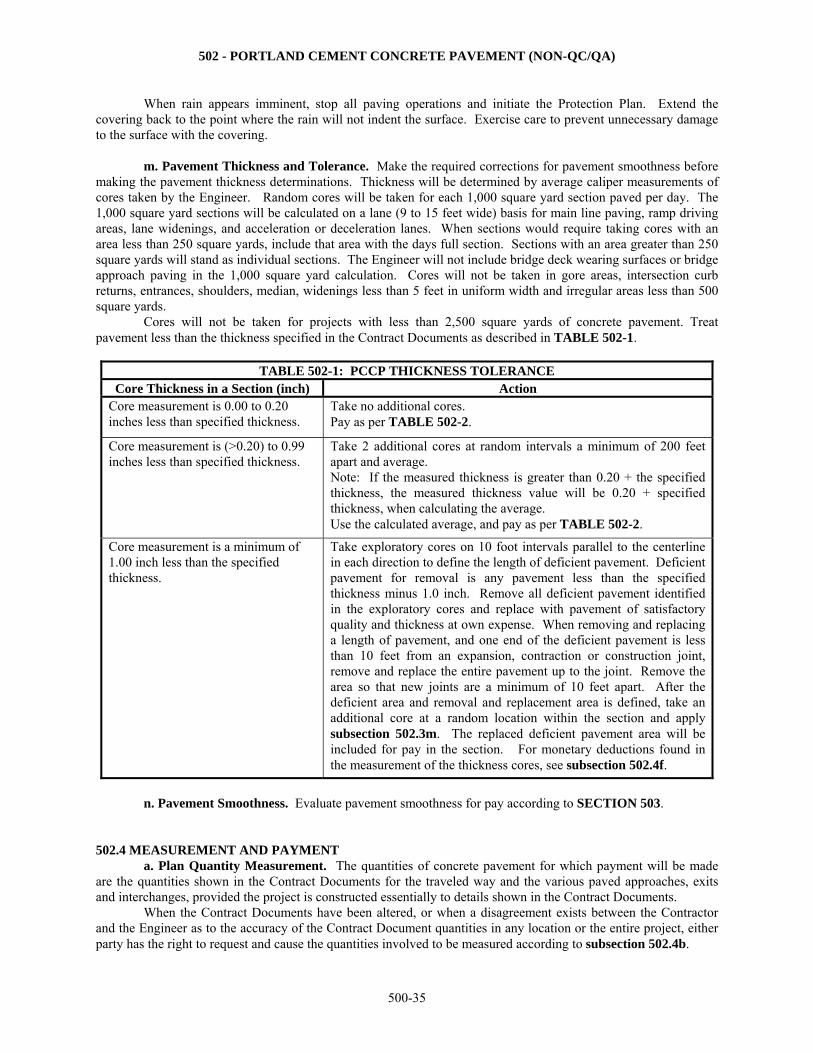
502 - PORTLAND CEMENT CONCRETE PAVEMENT (NON-QC/QA)
500-35
When rain appears imminent, stop all paving operations and initiate the Protection Plan. Extend the covering back to the point where the rain will not indent the surface. Exercise care to prevent unnecessary damage to the surface with the covering.
m. Pavement Thickness and Tolerance. Make the required corrections for pavement smoothness before
making the pavement thickness determinations. Thickness will be determined by average caliper measurements of cores taken by the Engineer. Random cores will be taken for each 1,000 square yard section paved per day. The 1,000 square yard sections will be calculated on a lane (9 to 15 feet wide) basis for main line paving, ramp driving areas, lane widenings, and acceleration or deceleration lanes. When sections would require taking cores with an area less than 250 square yards, include that area with the days full section. Sections with an area greater than 250 square yards will stand as individual sections. The Engineer will not include bridge deck wearing surfaces or bridge approach paving in the 1,000 square yard calculation. Cores will not be taken in gore areas, intersection curb returns, entrances, shoulders, median, widenings less than 5 feet in uniform width and irregular areas less than 500 square yards. Cores will not be taken for projects with less than 2,500 square yards of concrete pavement. Treat pavement less than the thickness specified in the Contract Documents as described in TABLE 502-1.
TABLE 502-1: PCCP THICKNESS TOLERANCE
Core Thickness in a Section (inch) Action Core measurement is 0.00 to 0.20 inches less than specified thickness.
Take no additional cores. Pay as per TABLE 502-2.
Core measurement is (>0.20) to 0.99 inches less than specified thickness.
Take 2 additional cores at random intervals a minimum of 200 feet apart and average. Note: If the measured thickness is greater than 0.20 + the specified thickness, the measured thickness value will be 0.20 + specified thickness, when calculating the average. Use the calculated average, and pay as per TABLE 502-2.
Core measurement is a minimum of 1.00 inch less than the specified thickness.
Take exploratory cores on 10 foot intervals parallel to the centerline in each direction to define the length of deficient pavement. Deficient pavement for removal is any pavement less than the specified thickness minus 1.0 inch. Remove all deficient pavement identified in the exploratory cores and replace with pavement of satisfactory quality and thickness at own expense. When removing and replacing a length of pavement, and one end of the deficient pavement is less than 10 feet from an expansion, contraction or construction joint, remove and replace the entire pavement up to the joint. Remove the area so that new joints are a minimum of 10 feet apart. After the deficient area and removal and replacement area is defined, take an additional core at a random location within the section and apply subsection 502.3m. The replaced deficient pavement area will be included for pay in the section. For monetary deductions found in the measurement of the thickness cores, see subsection 502.4f.
n. Pavement Smoothness. Evaluate pavement smoothness for pay according to SECTION 503.
502.4 MEASUREMENT AND PAYMENT a. Plan Quantity Measurement. The quantities of concrete pavement for which payment will be made are the quantities shown in the Contract Documents for the traveled way and the various paved approaches, exits and interchanges, provided the project is constructed essentially to details shown in the Contract Documents.
When the Contract Documents have been altered, or when a disagreement exists between the Contractor and the Engineer as to the accuracy of the Contract Document quantities in any location or the entire project, either party has the right to request and cause the quantities involved to be measured according to subsection 502.4b.
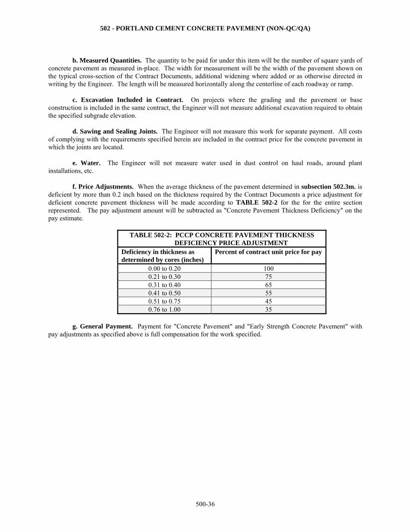
502 - PORTLAND CEMENT CONCRETE PAVEMENT (NON-QC/QA)
500-36
b. Measured Quantities. The quantity to be paid for under this item will be the number of square yards of
concrete pavement as measured in-place. The width for measurement will be the width of the pavement shown on the typical cross-section of the Contract Documents, additional widening where added or as otherwise directed in writing by the Engineer. The length will be measured horizontally along the centerline of each roadway or ramp.
c. Excavation Included in Contract. On projects where the grading and the pavement or base
construction is included in the same contract, the Engineer will not measure additional excavation required to obtain the specified subgrade elevation.
d. Sawing and Sealing Joints. The Engineer will not measure this work for separate payment. All costs
of complying with the requirements specified herein are included in the contract price for the concrete pavement in which the joints are located.
e. Water. The Engineer will not measure water used in dust control on haul roads, around plant
installations, etc. f. Price Adjustments. When the average thickness of the pavement determined in subsection 502.3m. is
deficient by more than 0.2 inch based on the thickness required by the Contract Documents a price adjustment for deficient concrete pavement thickness will be made according to TABLE 502-2 for the for the entire section represented. The pay adjustment amount will be subtracted as "Concrete Pavement Thickness Deficiency" on the pay estimate.
TABLE 502-2: PCCP CONCRETE PAVEMENT THICKNESS DEFICIENCY PRICE ADJUSTMENT
Deficiency in thickness as determined by cores (inches)
Percent of contract unit price for pay
0.00 to 0.20 100 0.21 to 0.30 75 0.31 to 0.40 65 0.41 to 0.50 55 0.51 to 0.75 45 0.76 to 1.00 35
g. General Payment. Payment for "Concrete Pavement" and "Early Strength Concrete Pavement" with
pay adjustments as specified above is full compensation for the work specified.
503 - PORTLAND CEMENT CONCRETE PAVEMENT SMOOTHNESS
500-37
SECTION 503
PORTLAND CEMENT CONCRETE PAVEMENT SMOOTHNESS 503.1 DESCRIPTION Determine the smoothness of the pavement surface. Correct the smoothness deficiencies discovered in the pavement surface.
BID ITEM UNITS Concrete Pavement Smoothness Lump Sum 503.2 MATERIALS - None specified. 503.3 CONSTRUCTION REQUIREMENTS a. General. Determine the pavement smoothness by profiling the pavement surface of through traffic lanes and ramps. Excluded from profilograph testing, and not eligible for pay adjustments, on all projects are:
bridge decks; acceleration and deceleration lanes of at-grade intersections; turning lanes; shoulders; pavement on horizontal curves with centerline radius of curvature of less than 1000 feet, and pavement
within the superelevation transition of such curves; individual sections of pavement less than 50 feet in length; sideroads less than 250 feet in length; and the first (or last) 15 feet of a pavement section where the Contractor is not responsible for the
adjoining surface county secondary projects b. Equipment. Use a California type profilograph, prequalified by the Bureau of Construction and Materials,
to determine the pavement profile. If approved by the Bureau of Construction and Materials, other types of profilographs that produce results compatible to the California type profilograph may be used. If the profilograph has a mechanical recorder, provide a ProScan electronic scanner with motorized paper transport to reduce the trace. Use the motorized paper transport when scanning the profilograph traces. The Bureau of Construction and Materials can provide the information necessary for the Contractor to obtain a ProScan electronic scanner. If approved by the Bureau of Construction and Materials, other types of automated trace reduction equipment may be used. If the profilograph has a computerized recorder, the trace produced is evaluated without further reduction.
Provide a self-propelled grinding machine specifically designed to grind and texture portland cement concrete pavement using diamond blades mounted on a multi-blade arbor. The arbor must contain enough blades to provide at least a 36-inch wide cutting head and provide 55 to 60 evenly spaced grooves per foot.
Do not use equipment that causes excessive ravels, aggregate fractures or spalls. Use equipment that provides a flat plane surface without crown and a uniform texture for the full width of the lane. Grind a nominal depth of 3/16 inch. When grinding is performed, use vacuum equipment or other continuous methods to remove grinding slurry and residue. Remove from the project and properly dispose of the material. Do not allow the grinding slurry to flow across lanes being used by traffic, onto shoulder slopes, into streams, lakes, ponds or other bodies of water, or gutters or other drainage facilities. Do not place grinding slurry on foreslopes.
Bush hammers or other impact devices will not be permitted. c. Profilograph Operation. Provide an operator for the profilograph certified according to KT-46, Part V. Determine the pavement profiles for each lane according to the procedures for 1 lane shown in Kansas Test
Method KT-46. Additional profiles may be taken only to define the limits of an out-of-tolerance surface variation. The
503 - PORTLAND CEMENT CONCRETE PAVEMENT SMOOTHNESS
500-38
Engineer may use a 10-foot straightedge (or other means) to detect irregularities outside the required trace paths. The Engineer may also use the straightedge to delineate the areas that require corrective action. Determine a profile index (in./mi.) for each pavement section of finished pavement. A pavement section is a continuous area of pavement surface 0.1 mile long by 1 lane wide (12 feet nominal). A partial pavement section resulting from an interruption (such as a bridge) of the continuous pavement surface is subject to the same testing and evaluation as a whole section.
During the initial paving operations (and after long shutdown periods), profile the pavement as soon as the concrete has cured sufficiently to permit testing. The Engineer and the Contractor will use the results of the initial testing to evaluate the paving methods and equipment. If the initial paving operation produces acceptable results, the Contractor may continue paving. Repair or replace any PCCP curing medium that is damaged or removed during the testing. On surfaces excluded from profilograph testing, the Engineer will determine the pavement smoothness using a 10-foot straightedge. The Engineer will select the locations to be tested. The variation of the surface from the testing edge of the straightedge shall not exceed ⅛ inch between any 2 contacts, longitudinal or transverse.
Correct all irregularities exceeding the specified tolerance using equipment and methods approved by the Engineer. After the irregularities are corrected, the Engineer will retest the area to verify compliance with the specified tolerance. d. Profilograph Evaluation and Corrective Actions. Evaluate the profilograph results according to KT-46. Provide the Engineer with the profilograms and their evaluation within 2 working days after placement of the pavement. Determine and evaluate the profile index (in./mi.) for each trace and the average profile index (in./mi.) for each section to identify required corrective action. Determine the daily average profile index (in./mi.) for each day’s paving operation. A day’s paving operation is the pavement placed in a day (a minimum of 1 pavement section).
If less than 1 pavement section is placed in a day, the day’s production is grouped with the next day’s production.
If the production of the last day of project paving is less than 1 pavement section, it is grouped with the previous day’s production.
The Contractor has the option of profiling the final portion of a day’s production (not to exceed 5 sections) the first working day that paving is continued in the same lane. If the Contractor opts to profilograph the final portion of a day’s paving the next working day that paving is continued in the same lane, those results (the final portion of the previous day’s paving) are grouped with the day’s paving as the lane is continued.
Make the required corrections for pavement smoothness before making the pavement thickness
determinations. Take the required corrective actions according to TABLE 503-1.
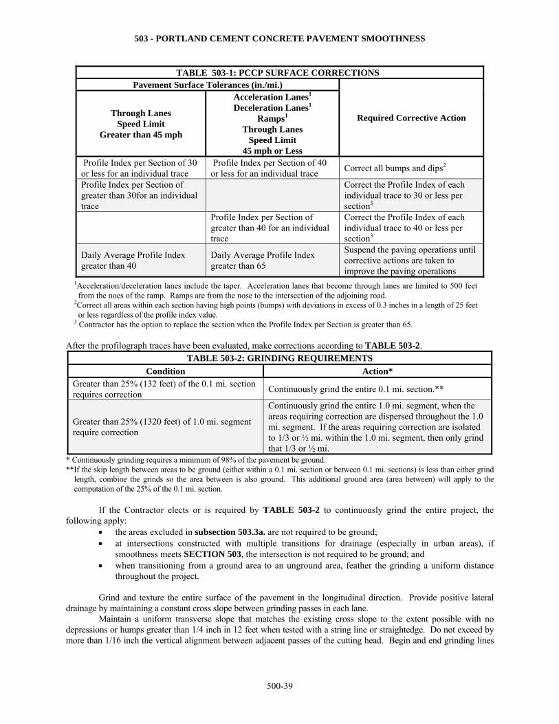
503 - PORTLAND CEMENT CONCRETE PAVEMENT SMOOTHNESS
500-39
TABLE 503-1: PCCP SURFACE CORRECTIONS Pavement Surface Tolerances (in./mi.)
Required Corrective Action Through Lanes Speed Limit
Greater than 45 mph
Acceleration Lanes1
Deceleration Lanes1
Ramps1
Through Lanes Speed Limit
45 mph or Less
Profile Index per Section of 30 or less for an individual trace
Profile Index per Section of 40 or less for an individual trace
Correct all bumps and dips2
Profile Index per Section of greater than 30for an individual trace
Correct the Profile Index of each individual trace to 30 or less per section3
Profile Index per Section of greater than 40 for an individual trace
Correct the Profile Index of each individual trace to 40 or less per section3
Daily Average Profile Index greater than 40
Daily Average Profile Index greater than 65
Suspend the paving operations until corrective actions are taken to improve the paving operations
1Acceleration/deceleration lanes include the taper. Acceleration lanes that become through lanes are limited to 500 feet from the noes of the ramp. Ramps are from the nose to the intersection of the adjoining road.
2Correct all areas within each section having high points (bumps) with deviations in excess of 0.3 inches in a length of 25 feet or less regardless of the profile index value.
3 Contractor has the option to replace the section when the Profile Index per Section is greater than 65. After the profilograph traces have been evaluated, make corrections according to TABLE 503-2.
TABLE 503-2: GRINDING REQUIREMENTS
Condition Action* Greater than 25% (132 feet) of the 0.1 mi. section requires correction
Continuously grind the entire 0.1 mi. section.**
Greater than 25% (1320 feet) of 1.0 mi. segment require correction
Continuously grind the entire 1.0 mi. segment, when the areas requiring correction are dispersed throughout the 1.0 mi. segment. If the areas requiring correction are isolated to 1/3 or ½ mi. within the 1.0 mi. segment, then only grind that 1/3 or ½ mi.
* Continuously grinding requires a minimum of 98% of the pavement be ground. **If the skip length between areas to be ground (either within a 0.1 mi. section or between 0.1 mi. sections) is less than either grind
length, combine the grinds so the area between is also ground. This additional ground area (area between) will apply to the computation of the 25% of the 0.1 mi. section.
If the Contractor elects or is required by TABLE 503-2 to continuously grind the entire project, the following apply:
the areas excluded in subsection 503.3a. are not required to be ground; at intersections constructed with multiple transitions for drainage (especially in urban areas), if
smoothness meets SECTION 503, the intersection is not required to be ground; and when transitioning from a ground area to an unground area, feather the grinding a uniform distance
throughout the project. Grind and texture the entire surface of the pavement in the longitudinal direction. Provide positive lateral
drainage by maintaining a constant cross slope between grinding passes in each lane. Maintain a uniform transverse slope that matches the existing cross slope to the extent possible with no
depressions or humps greater than 1/4 inch in 12 feet when tested with a string line or straightedge. Do not exceed by more than 1/16 inch the vertical alignment between adjacent passes of the cutting head. Begin and end grinding lines
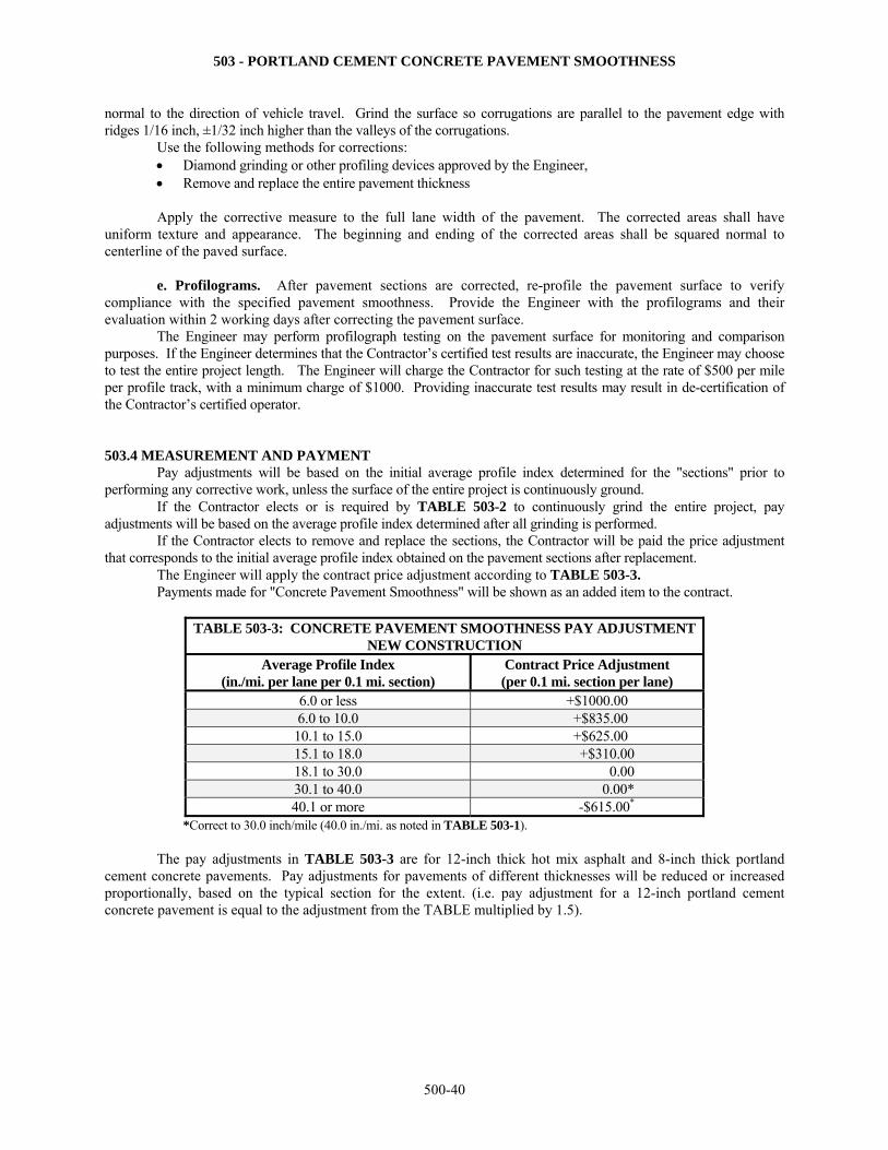
503 - PORTLAND CEMENT CONCRETE PAVEMENT SMOOTHNESS
500-40
normal to the direction of vehicle travel. Grind the surface so corrugations are parallel to the pavement edge with ridges 1/16 inch, ±1/32 inch higher than the valleys of the corrugations. Use the following methods for corrections:
Diamond grinding or other profiling devices approved by the Engineer, Remove and replace the entire pavement thickness
Apply the corrective measure to the full lane width of the pavement. The corrected areas shall have
uniform texture and appearance. The beginning and ending of the corrected areas shall be squared normal to centerline of the paved surface.
e. Profilograms. After pavement sections are corrected, re-profile the pavement surface to verify compliance with the specified pavement smoothness. Provide the Engineer with the profilograms and their evaluation within 2 working days after correcting the pavement surface. The Engineer may perform profilograph testing on the pavement surface for monitoring and comparison purposes. If the Engineer determines that the Contractor’s certified test results are inaccurate, the Engineer may choose to test the entire project length. The Engineer will charge the Contractor for such testing at the rate of $500 per mile per profile track, with a minimum charge of $1000. Providing inaccurate test results may result in de-certification of the Contractor’s certified operator. 503.4 MEASUREMENT AND PAYMENT Pay adjustments will be based on the initial average profile index determined for the "sections" prior to performing any corrective work, unless the surface of the entire project is continuously ground.
If the Contractor elects or is required by TABLE 503-2 to continuously grind the entire project, pay adjustments will be based on the average profile index determined after all grinding is performed. If the Contractor elects to remove and replace the sections, the Contractor will be paid the price adjustment that corresponds to the initial average profile index obtained on the pavement sections after replacement. The Engineer will apply the contract price adjustment according to TABLE 503-3. Payments made for "Concrete Pavement Smoothness" will be shown as an added item to the contract.
TABLE 503-3: CONCRETE PAVEMENT SMOOTHNESS PAY ADJUSTMENT NEW CONSTRUCTION
Average Profile Index (in./mi. per lane per 0.1 mi. section)
Contract Price Adjustment (per 0.1 mi. section per lane)
6.0 or less +$1000.00
6.0 to 10.0 +$835.00 10.1 to 15.0 +$625.00 15.1 to 18.0 +$310.00 18.1 to 30.0 0.00 30.1 to 40.0 0.00* 40.1 or more -$615.00*
*Correct to 30.0 inch/mile (40.0 in./mi. as noted in TABLE 503-1).
The pay adjustments in TABLE 503-3 are for 12-inch thick hot mix asphalt and 8-inch thick portland cement concrete pavements. Pay adjustments for pavements of different thicknesses will be reduced or increased proportionally, based on the typical section for the extent. (i.e. pay adjustment for a 12-inch portland cement concrete pavement is equal to the adjustment from the TABLE multiplied by 1.5).
504 – DOWEL BAR RETROFIT-REPAIR NEW PCCP
500-41
SECTION 504
DOWEL BAR RETROFIT-REPAIR NEW PCCP 504.1 DESCRIPTION Cut slots normal to the transverse cracks and place epoxy-coated steel dowel bars to repair the newly constructed Portland Cement Concrete Pavement (PCCP) that is damaged. See Standard Drawing RD723, latest version. 504.2 MATERIALS a. Epoxy-Coated Dowel Bars. Provide epoxy-coated steel dowel bars that comply with DIVISION 1600. Provide a tight fitting nonmetallic expansion cap on one end of the dowel bars. The Engineer must approve the expansion cap before it is used. Provide epoxy-coated or nonmetallic chair devices to support and hold the dowel bars. The Engineer must approve the chair devices before they are used. b. Bondbreaker for Dowel Bars. Provide a bondbreaker that complies with DIVISION 1700. c. Caulking Filler. Provide a silicone sealant caulking filler intended for filling cracks in PCCP. The Engineer must approve the caulking filler before it is used. d. Board Filler. Provide a closed-cell foam core board filler (the width of the joint thick) faced with poster board material on each side. The Engineer must approve the board filler before it is used. e. Grout. Provide a product that complies with DIVISION 1700 and is prequalified as “very rapid hardening” when extended. The grout may be extended as the manufacturer recommends. The extender aggregate must be of size to allow complete distribution and consolidation around the bar. For practical purposes the maximum aggregate size should be no more than 1/2 the size of the distance between the dowel bar and the adjacent concrete pavement. All extender aggregate used on contracts must be from a source that has a current Official Quality approval status for Mixed Aggregate per DIVISION 1100. f. Liquid Membrane-Forming Compound. Provide a liquid membrane-forming compound that complies with DIVISION 1400. 504.3 CONSTRUCTION REQUIREMENTS Cut slots for the dowel bars into the PCCP as needed to repair the damaged PCCP. Use a gang saw capable of simultaneously cutting all the slots at one location (one wheel path). A single or dual blade saw may be used provided the production rate for sawing equals or exceeds 15 slots per hour. Hand saws are prohibited. Make the slots large enough to provide the minimum clearances shown in the Contract Documents. If necessary, make multiple parallel saw cuts to remove the existing concrete from the slot. If jackhammers are used to break the concrete loose, do not use jackhammers larger than the nominal 15 pound class. Sandblast and clean all surfaces of the slot. Sandblast and clean all cracks in the slot. Remove all broken concrete and debris from the project. Fill the transverse crack in the bottom and sides of the slot with caulking filler. Prevent the caulking filler from contacting the surfaces outside the crack. Before the dowel bar is placed in the slot, cut a piece of the board filler material to fit tightly around the dowel bar and against the bottom and sides of the slot. Place the board filler material vertically above the transverse crack in the bottom of the slot and prevent it from being displaced in the slot. Keep the board filler material in this position during placement of the grout. Use chair devices to position and hold the dowel bars parallel (± 1/8 inch) to the pavement centerline and the pavement surface, and at the depth shown in the Contract Documents. Coat the dowel bars with an approved bondbreaker before the grout is placed.
504 – DOWEL BAR RETROFIT-REPAIR NEW PCCP
500-42
Place and consolidate the grout as recommended by the manufacturer. Cure the surface of the grouted slots with a liquid membrane-forming compound. The extended grout must obtain a minimum of 2000 psi compressive strength before the roadway can be opened to traffic, but no sooner than 2 hours. Provide data that accounts for actual temperatures work is being performed. Saw the transverse joint through the patched areas within 24 hours of the placement of the grout. Saw and seal the joint as shown in the Contract Documents. 504.4 MEASUREMENT AND PAYMENT
This work is subsidiary to bid items in DIVISIONS 501 and 502.
505 – TIE BAR INSERTION-REPAIR NEW PCCP
500-43
SECTION 505
TIE BAR INSERTION-REPAIR NEW PCCP
505.1 DESCRIPTION Drill holes and anchor deformed tie bar reinforcement diagonally across all longitudinal cracks and only those transverse cracks that extend partial depth, as determined through coring, to repair the newly constructed Portland Cement Concrete Pavement (PCCP) that is damaged. See Standard Drawing RD723, latest version. 505.2 MATERIALS a. Tie Bars. Provide epoxy-coated (including the ends) deformed reinforcing steel bars, hereafter referred to as tie bars that comply with SECTION 1600. b. Anchoring System. Use Type IV, Grade 1 - low viscosity Epoxy-Resin-Based Bonding System and the Class that complies with SECTION 1700. 505.3 CONSTRUCTION REQUIREMENTS a. Equipment. Use hydraulic or handheld pneumatic or electric drills with tungsten carbide bits. Control the forward and reverse travel of the drills by mechanically applied pressure. Mount the drill on a suitable piece of equipment such that it is quickly transported and positioned. Rest and reference the drill rig frame on and to the pavement surface such that the drilled holes are cylindrical and repeatable in terms of position and alignment on the surface being drilled. Handheld drills may be used when they can be demonstrated to produce the same results as hydraulic drills with regard to drilling cylindrical holes and repeatable in terms of position and alignment. The Engineer may establish production rates for the hand-held drills. b. General. Drill the holes in a slab at the offset, depth and angle shown in the Contract Documents. Drill such that the:
Centerline of the holes is perpendicular to the crack/joint (in plan view) at each location being drilled. Adjacent holes are drilled in opposite directions across the crack/joint.
Repair cracks and spalls that result from drilling with a partial or full-depth repair as directed by the
Engineer. Clean the drilled holes (and chipped areas at the surface resulting from drilling) in accordance with the anchoring material manufacturer’s written recommendations. Submit recommendations to the Engineer before drilling any holes. As a minimum, clean holes with oil-free and moisture-free compressed air. The Engineer will check the compressed air stream purity with a clean white cloth. Use a compressor that delivers air at a minimum flow volume of 120 cubic feet per minute and develops a minimum nozzle pressure of 90 psi. Insert the nozzle to the back of the hole to force out all dust and debris. Place the anchoring system material into the back of the hole using a nozzle or wand of sufficient length. Insert the tie bar such that the anchoring material is evenly distributed around the tie bar. Use an amount that slightly extrudes out the hole as the tie bar is inserted. Remove the excess and trowel the anchoring material smooth to the pavement surface, filling any chipped areas. Do not allow traffic on the repaired area until the anchoring material is cured as recommended by the manufacturer’s specifications. 505.4 MEASUREMENT AND PAYMENT
This work is subsidiary to bid items in DIVISIONS 501 and 502.
