division f drawing standards index › sites › default › files... · 11/14/2019 drawing...
TRANSCRIPT

11/14/2019 F-1
DIVISION F DRAWING STANDARDS INDEX F.1 GENERAL ...................................................................................................................................... 2 F.2 DRAWING STANDARDS............................................................................................................... 3 F.3 ADDENDUM FOR DRAWING STANDARDS .................................................................................. 4 F.4 TITLE BLOCK ................................................................................................................................ 5 F.5 DRAWING TITLES ......................................................................................................................... 5 F.6 DRAWING CHECKLIST................................................................................................................. 5 F.7 CRITERIA FOR ASSIGNING ROOM NUMBERS ......................................................................... 6 F.8 DRAWING SYMBOLS ................................................................................................................... 7 F.9 ARCHITECTURAL SYMBOLS ...................................................................................................... 8 F.10 ELECTRICAL SYMBOLS............................................................................................................... 9 F.11 MECHANICAL SYMBOLS ........................................................................................................... 14 F.12 TITLE BLOCK EXAMPLE ............................................................................................................ 19 F.13 KEY PLAN EXAMPLE .................................................................................................................. 20 F.14 CAMPUS BUILDING LOCATOR MAP ........................................................................................ 21

11/14/2019 Drawing Standards Division F-2
DIVISION F DRAWING STANDARDS
F.1 GENERAL
A. 1. The Office of Facilities Management has the responsibility for the care, use, storage and retrieval of all architectural and engineering drawings done by and for the University of Pittsburgh. This applies to drawings generated by projects contracted to outside Professionals as well as in-house design.
2. Facilities Management has developed these standards for continuity and to ensure that
certain drawing standards and instructions are applied to drawings produced by and for the University.
B. Drawings shall contain:
1. Adequate information to include schedules, details and pertinent information to perform the work.
2. Uniformity of methodology.
3. Uniformity of drawing size.
4. University assigned Job Numbers, Drawing Numbers, and Room Numbers.
5. Professional stamp and signature on drawings.
6. The cover sheet on new construction projects shall include the building construction
type and fire resistance ratings for building elements.
C. 1. Construction drawings must be submitted to Facilities Management in AutoCAD and PDF format. Contact Technical Services at Facilities Management during DD phase to verify what versions are acceptable.
2. Each CAD construction drawing, floor plan, elevation, etc., must have its own separate
CAD file. CAD floor plans must stack properly above on another with an insertion point of (0,0,0).
3. Drawings shall be drawn at full scale, 1 inch = 1 inch.
4. X-refs shall not be used. If unavoidable, X-ref’s shall be converted to blocks using
the X-ref bind (insert) command.
5. Unless the drawing is specifically intended to be 3D, great care should be taken to ensure that lines, blocks, etc., are drawn at and have a Z value of 0 (zero).
6. One Set of electronic files shall be submitted on a USB OR electronically through an FTP SITE in AutoCAD and Adobe PDF, accompanied by an index file. The index file should be an Excel file describing the contents of each sheet.

11/14/2019 Drawing Standards Division F-3
D. Facilities Management's Technical Services Support Group will provide assistance in the development of documents, and provide key plans, reference prints, archival information, drawing numbers and is also responsible for assigning appropriate room numbers to new configurations.
F.2. DRAWING STANDARDS A. Standard drawing sizes shall be 24" X 36" or 30" X 42", with current University Title Block. (See
Sample Attached) B. Exceptions to the above drawing sizes must be approved BEFORE drawings are made. C. A minimum 3/32” size lettering will be permitted when space is limited, but larger point
sizes are preferred. D. Projects with five (5) or more drawings shall have a Cover Sheet with an Index listing of
drawings, showing the reference number of each drawing and a Descriptive Title of the Drawing.
E. The cover sheet shall show the Name of the Project, the Job number, a Key Plan, Legend and
a Complete List of Drawings with their Drawing Numbers. F. A Legend showing reference symbols and abbreviations used in the preparation of the
drawings, with a clear explanation of each must appear on appropriate drawings. G. Each set of drawings shall include General, HVAC, Plumbing and Electrical notes where
applicable. Notes shall indicate areas of Owner/Contractor responsibilities and any special conditions or instructions relating to the work to be performed.
H. Drawings shall include Structural Notes describing Live Loads used in the structural design and
highlight any Structural Design Characteristics such as post-tensioning, etc. which may have to be taken into consideration in future renovations of the structure.
I. Each drawing shall show a reference to the drawings having the Notes and Legends. Lettering
must be 3/32”, or larger.
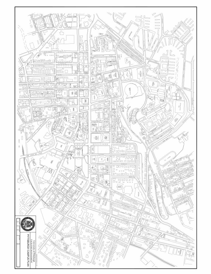
J. Drawings that show a floor plan or partial plan, shall show a Campus North Arrow and a Key Plan indicating Area of Renovation or Alteration, Nearest Street, and Best access for the Contractors (See Campus Plan attached).
K. Plan drawings shall show Column and Row identification as shown on the original building
construction drawings, where applicable.
L. Room Numbers shall be assigned by Facilities Management's Technical Services Office via the Project Manager. Room Numbers must be assigned as soon as the new design configuration has been approved. Architectural design shall be coordinated with Mechanical, Plumbing and Electrical Design regarding new or changed room numbers.
M. Fire Walls and Smoke Barriers shall be defined and identified on the drawings; openings or
penetrations shall be fully coordinated with all disciplines. N. Specifications shall be a part of every design project. Drawings and Specifications shall be
submitted to the assigned Project Manager for circulation and review.

11/14/2019 Drawing Standards Division F-4
O. During the construction period, Contractors must provide "As-Built" prints to the Professional of Record. The Professional shall revise the original drawings accordingly and supply Facilities Management with revised AutoCAD files and PDF files. NOTE: Payment of last invoice for Professional services will not be released until these reproducible drawings are provided to the Project Manager.
P. Drawings shall bear a Professional Stamp with Signature. Q. Standard symbols have been adopted by Facilities Management for the development of
drawing documents. Certain primary Architectural, Mechanical, Plumbing and Electrical Reference Symbols shall be used (refer to illustrations provided in this Division).
R. Drawings not conforming to these standards shall be corrected by the Professional at no cost
to the University. F.3 ADDENDUM TO DRAWING STANDARDS Providing "As Built" Drawings:
1. AutoCAD is the method of preference for drawings done by and for the University of Pittsburgh.
2. Original bid drawings plotted on reproducible media and "as builts" provided on a USB
OR electronically through an FTP SITE in an AutoCAD compatible format will satisfy the requirements of the University.
3. Drawing files using AutoCAD-compatible software i.e., MicroStation, etc., must be
formatted and provided as AutoCAD.DWG, and must be accompanied by hard copy.
4. USB OR an FTP SITE are acceptable for delivery of electronic files.
5. The Professional must provide original drawings to the University for bid and construction prints, and is responsible for obtaining "as built" information from the Contractor and revising the originals.
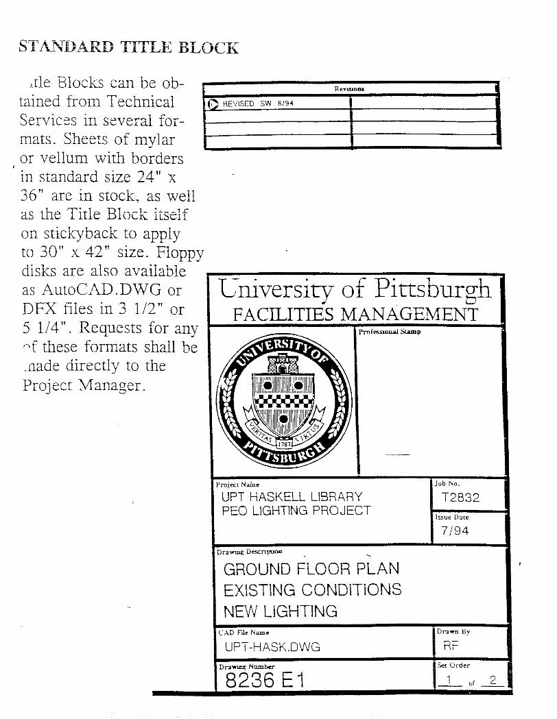
F.4 TITLE BLOCK
A. Title Block shall be standard University of Pittsburgh as shown in this manual. B. Title Block shall state Building Name, Area of Renovation, and Clear Description of what
is being conveyed on the drawings. C. A Drawing File Number shall be assigned by the Technical Services Office via the Project
Manager. This number shall be shown in the title block along with the University's Project Job Number.
D. A Categorized Sequential Number shall accompany the assigned drawing number, i.e.
XXXX A1, XXXX A2 etc. E. Total Number of Complete Working Drawings in Set, including all disciplines, shall be
indicated on the Title Block to the right of Categorized Sequential Number, and also on the cover sheet. For example: (2 of 5), (9 of 15) etc.
11/14/2019 Drawing Standards Division F-5
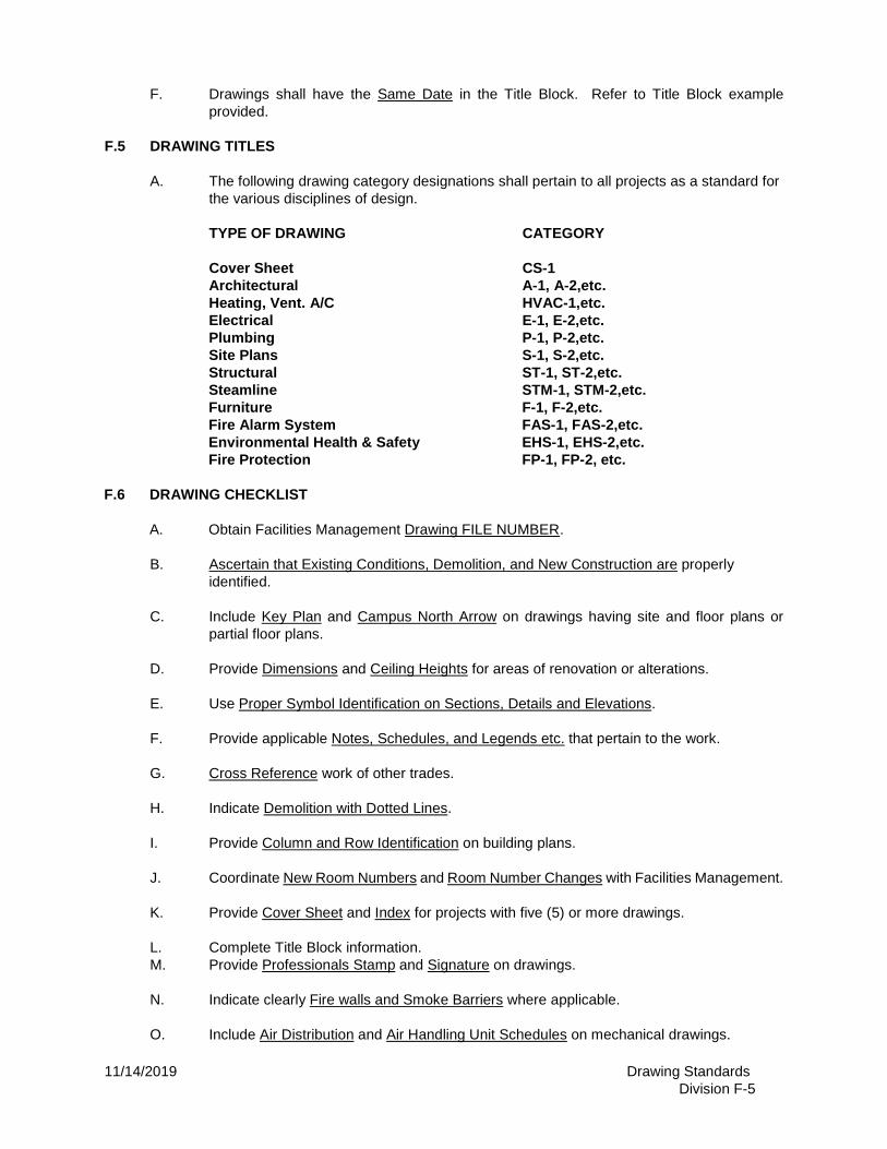
F. Drawings shall have the Same Date in the Title Block. Refer to Title Block example provided.
F.5 DRAWING TITLES A. The following drawing category designations shall pertain to all projects as a standard for
the various disciplines of design. TYPE OF DRAWING CATEGORY Cover Sheet CS-1 Architectural A-1, A-2,etc. Heating, Vent. A/C HVAC-1,etc. Electrical E-1, E-2,etc. Plumbing P-1, P-2,etc. Site Plans S-1, S-2,etc. Structural ST-1, ST-2,etc. Steamline STM-1, STM-2,etc. Furniture F-1, F-2,etc. Fire Alarm System FAS-1, FAS-2,etc. Environmental Health & Safety EHS-1, EHS-2,etc. Fire Protection FP-1, FP-2, etc. F.6 DRAWING CHECKLIST A. Obtain Facilities Management Drawing FILE NUMBER. B. Ascertain that Existing Conditions, Demolition, and New Construction are properly
identified. C. Include Key Plan and Campus North Arrow on drawings having site and floor plans or
partial floor plans. D. Provide Dimensions and Ceiling Heights for areas of renovation or alterations. E. Use Proper Symbol Identification on Sections, Details and Elevations. F. Provide applicable Notes, Schedules, and Legends etc. that pertain to the work. G. Cross Reference work of other trades. H. Indicate Demolition with Dotted Lines. I. Provide Column and Row Identification on building plans. J. Coordinate New Room Numbers and Room Number Changes with Facilities Management. K. Provide Cover Sheet and Index for projects with five (5) or more drawings. L. Complete Title Block information. M. Provide Professionals Stamp and Signature on drawings. N. Indicate clearly Fire walls and Smoke Barriers where applicable. O. Include Air Distribution and Air Handling Unit Schedules on mechanical drawings.
11/14/2019 Drawing Standards Division F-6
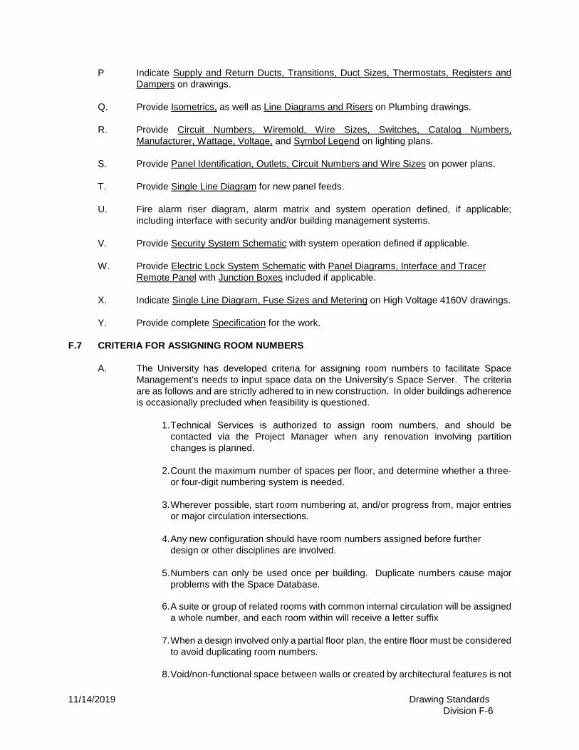
P Indicate Supply and Return Ducts, Transitions, Duct Sizes, Thermostats, Registers and
Dampers on drawings. Q. Provide Isometrics, as well as Line Diagrams and Risers on Plumbing drawings. R. Provide Circuit Numbers, Wiremold, Wire Sizes, Switches, Catalog Numbers,
Manufacturer, Wattage, Voltage, and Symbol Legend on lighting plans. S. Provide Panel Identification, Outlets, Circuit Numbers and Wire Sizes on power plans. T. Provide Single Line Diagram for new panel feeds. U. Fire alarm riser diagram, alarm matrix and system operation defined, if applicable;
including interface with security and/or building management systems. V. Provide Security System Schematic with system operation defined if applicable. W. Provide Electric Lock System Schematic with Panel Diagrams, Interface and Tracer
Remote Panel with Junction Boxes included if applicable. X. Indicate Single Line Diagram, Fuse Sizes and Metering on High Voltage 4160V drawings. Y. Provide complete Specification for the work. F.7 CRITERIA FOR ASSIGNING ROOM NUMBERS A. The University has developed criteria for assigning room numbers to facilitate Space
Management’s needs to input space data on the University’s Space Server. The criteria are as follows and are strictly adhered to in new construction. In older buildings adherence is occasionally precluded when feasibility is questioned.
1. Technical Services is authorized to assign room numbers, and should be
contacted via the Project Manager when any renovation involving partition changes is planned.
2. Count the maximum number of spaces per floor, and determine whether a three‐
or four‐digit numbering system is needed.
3. Wherever possible, start room numbering at, and/or progress from, major entries or major circulation intersections.
4. Any new configuration should have room numbers assigned before further
design or other disciplines are involved.
5. Numbers can only be used once per building. Duplicate numbers cause major problems with the Space Database.
6. A suite or group of related rooms with common internal circulation will be assigned
a whole number, and each room within will receive a letter suffix
7. When a design involved only a partial floor plan, the entire floor must be considered to avoid duplicating room numbers.
8. Void/non‐functional space between walls or created by architectural features is not

11/14/2019 Drawing Standards Division F-7
numbered.
9. Numbers are arranged on each floor to follow an ascending order if possible, such as 201 being directly above 101, etc.
10. Each door with a lock needs to be identified for tumblers to be set, keys cut
and control of key distribution. When a space has more than one (1) door, all doors have the same number installed on the side leading into that space, but the space itself has only one number.
F.7.1 CLOSE OUT DOCUMENTS During the construction period, Contractors must provide "As-Built" prints to the Professional of Record. The Professional shall revise the original drawings accordingly and supply Facilities Management with revised AutoCAD files and PDF files on a USB or FTP SITE.
NOTE: Payment of last invoice for Professional services will not be released until these reproducible drawings/electronic files are provided to the Project Manager.
OPERATION AND MAINTENANCE MANUALS
Responsibility: Architect/Engineer, coordinated by the Project Manager
Purpose: to take over maintenance with written instructions sufficient to insure operations and maintenance in accordance with manufacturer’s specifications.
Format: Submit final approved O&M Manual prior to Substantial completion. Final submission shall include three hard copies and one electronic copy (PDF) on a USB or FTP SITE.
Content:
A. Certificate of Occupancy (Copy)
B. Signed Permits (Originals)
C. Phone Lists: Names, addresses, telephones numbers, “person to contact (if known) of
subcontractors, their suppliers, manufacturers’ representative, available service facilities and
normal channels of supply.
a. Design Intent of Building Systems
b. Drawings, Flowcharts, Riser Diagrams, Zone Control Layouts, other visual aids showing
the components and their relationship to the entire system.
D. Manuals of Systems Components to be Specified by Architect: The Architect shall specify, as
applicable:
a. Manufacturer’s printed installation and operating instructions: technical specifications and
instructions, not “sales” brochures/promotional material. Instructions shall include all
11/14/2019 Drawing Standards Division F-8
modes of operation in sufficient detail to be readily understood by Stanford maintenance
personnel.
b. Complete information on actual equipment installed as described in the manufacturers’
instructions, including dimensional drawings, model, type, size, capacity, performance
parameters such as curves, efficiencies, power requirements, operating ranges, etc. (Only
one manual is needed for multiple, identical equipment.
c. Serial numbers for all equipment
d. Detailed Parts List showing manufacturers’ parts numbers and such other identification as
necessary to facilitate procurement of spare or renewal parts and Owner-Manufacturer
communications.
e. Schedules showing proper time intervals for lubrication, adjustment, calibration or
checking. Contractor shall consolidate manufacturers’ schedules with a single master
schedule of required maintenance. This requirement is for the Contractor’s as well as the
Owner’s protection to insure proper early maintenance during the warranty period.
NOTE: Payment of last invoice for Professional services will not be released until the Operation and Maintenance manuals, as noted above, are provided to the Project Manager.
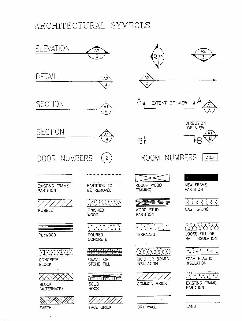
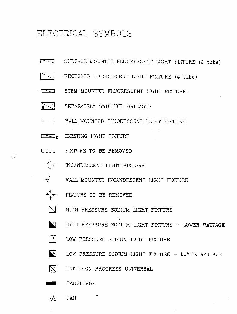
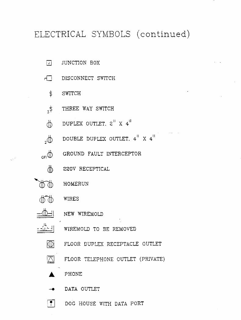
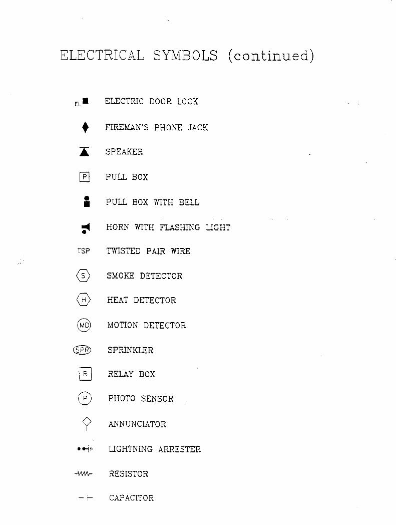
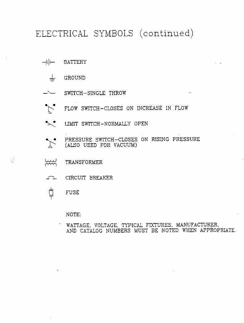
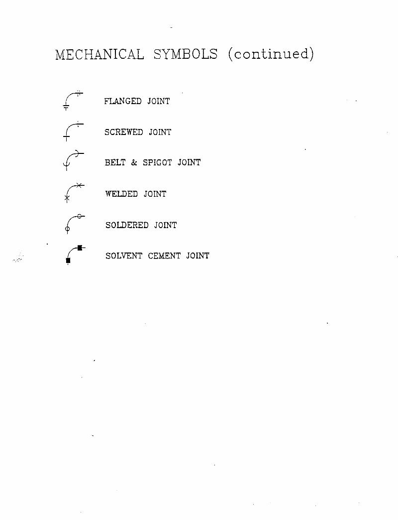
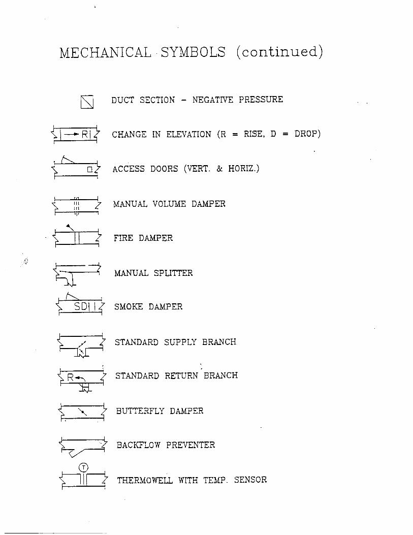
F.8 DRAWING SYMBOLS The following are Standard Symbols for drawings designed for the University of Pittsburgh.
Designers are expected to adhere to these symbols. To symbolize other information for which no standard is illustrated in Division F, Designers may use their discretion about other commonly used symbols.
END OF DIVISION