division iii roadway construction - virginia ... iii – roadway construction special provision...
TRANSCRIPT

Last Saved: 04/01/2016 2:41 PM UPDATED Apr 1, 2016 Today’s Date: April 1, 2016
*These SPECIFICATIONS REVISIONS are subject to change on short notice.
III-1
DIVISION III – ROADWAY CONSTRUCTION
SPECIAL PROVISION COPIED NOTES (SPCNs), SPECIAL PROVISION (SPs) and SUPPLEMENTAL
SPECIFICATIONS (SSs)
VDOT web file users (“pdf”) may obtain more information and other resources by downloading the accompanying “zip” file (compressed WORD
® files).
http://www.virginiadot.org/business/resources/const/07ImpRev.zip These sheets may also be found at the following locations:
Global Web Access: http://www.virginiadot.org/business/const/spec-default.asp
VDOT Only Access: https://outsidevdot.cov.virginia.gov/P0JQP/2007_Standard_Specifications/Forms/AF.aspx
________________________________________________________
TABLE OF CONTENTS
———— STANDARD 300 SERIES SPCNs, SPs and SSs ———— .................................................... 3-1
(c302h00) SECTION 302.03(b) PRECAST DRAINAGE STRUCTURES 1-14-08 (SPCN) ................ 3-2
(c303kg0) AGGREGATE MATERIAL Re. 7-08c (SPCN) .................................................................. 3-2
S302B00 - RESTORING EXISTING PAVEMENT 1-14-08cc ............................................................ 3-3
S302G02 - FLOWABLE BACKFILL 3-11-10 ...................................................................................... 3-6
S302H01 - TEMPORARY VEHICULAR WATERCOURSE CROSSING 3-25-09 ............................. 3-8
S303DP0 - NO PLAN AND MINIMUM PLAN CONCEPT Re. 7-08c .................................................. 3-10
S303J00 - TURBIDITY CURTAIN 1-14-08c ....................................................................................... 3-12
S303L00 - TEMPORARY SILT FENCE TYPE B 3-10-14 ................................................................ 3-14
S305BM2 - STABILIZED AND PAVED SHOULDER OVERLAY 12-3-15 ........................................ 3-16
S305EM1 - SHOULDER RENOVATION 12-9-15 .............................................................................. 3-19

Last Saved: 04/01/2016 2:41 PM UPDATED Apr 1, 2016 Today’s Date: April 1, 2016
*These SPECIFICATIONS REVISIONS are subject to change on short notice.
III-2
S312CM1 - BLOTTED SEAL COATS 8-22-08c ................................................................................ 3-23
S312DM2 - EMULSIFIED ASPHALT SLURRY SEAL 9-28-12 ........................................................ 3-25
S312EM2 - LATEX MOD. EMULSION TREATMENT (MICRO-SURFACING) 8-10-10 .................... 3-30
S314CM3 - ASPHALT SURFACE TREATMENT 9-13-12................................................................. 3-36
S314DM1 - MACRO-TEXTURE SURFACE TREATMENT 11-6-09 ................................................. 3-41
S315AA0 - COLD CENTRAL PLANT RECYCLING MATERIAL 8-7-15 ........................................ 3-46
S315AB0 - COLD CENTRAL PLANT RECYCLING MATERIAL PLACEMENT 8-7-15 ................. 3-54
S315AC0 - COLD IN-PLACE RECYCLING (CIR) 8-7-15 ............................................................... 3-59
S315AD0 - FULL-DEPTH RECLAMATION (FDR) 8-7-15 .............................................................. 3-70
S315AE0 - ASP. CONC. SCRATCH/LEVEL COURSE PRIOR PLA. MIX OVERLAY 9-24-15 ........ 3-79
S315HP0 - SECTION 315—ASPHALT CONCRETE PLACEMENT 1-29-16 ................................. 3-81
S315LM2 - SURFACE PREPARATION & RESTORATION PRIOR TO OVERLAY 2-2-11 ............ 3-100
S315NM5 - PLACEMENT OF ASPHALT CONCRETE OVERLAYS 12-3-15 ................................... 3-102
S315OM0 - TRENCH WIDEN. ASP. MIX BM-25.0(T), IM-19.0D(T) or IM19.0A(T) 10-17-08cc ........ 3-107
S315QM1 - LIMITS OF MAINLINE OVERLAY AT INTERSECTIONS 7-28-10 .............................. 3-109
S315R01 - RIDEABILITY 1-22-15 .................................................................................................. 3-111
S315SM1 - SEALING CRACKS IN ASP. CONC. / HYDR. CEM. CONC. PAVE. 10-19-14 ........... 3-115
S315U02 - DENSE GRADED ASPHALT MIX TYPE SM-4.75 10-16-15 ....................................... 3-119
S315V01 - BM-25.0D WITH INCREASED ASPHALT CONTENT 10-19-14 ................................... 3-123
S315Z00 - PAVEMENT SHOULDER WEDGE 12-4-13 ................................................................. 3-126
S316B00 - RIDEABILITY FOR HYDRAULIC CEMENT CONC. PAVE. Re.7-08c .......................... 3-128
S316D00 - SEALING SHOULDER JOINTS Re. 7-08c .................................................................... 3-130
SS30101 - SUPP. SEC. 301—CLEARING AND GRUBBING 9-3-14.............................................. 3-131
SS30204 - SUPP. SEC. 302—DRAINAGE STRUCTURES 3-14-13 ............................................... 3-132
SS30306 - SUPP. SEC. 303—EARTHWORK 9-3-14 ..................................................................... 3-141
SS30401 - SUPP. SEC. 304—CONSTRUCTING DENSITY CONTROL STRIPS 4-27-11 ............. 3-145
SS30601 - SUPP. SEC. 306—LIME STABILIZATION 10-2-08 ........................................................ 3-146
Last Saved: 04/01/2016 2:41 PM UPDATED Apr 1, 2016 Today’s Date: April 1, 2016
*These SPECIFICATIONS REVISIONS are subject to change on short notice.
III-3
SS31001 - SUPP. SEC. 310—TACK COAT 12-4-15 ........................................................................ 3-149
SS31510 - SUPP. SEC. 315—ASPHALT CONCRETE PLACEMENT 12-2-14c ............................. 3-153
SS31601 - SUPP. SEC. 316—HYDRAULIC CEMENT CONCRETE PAVEMENT 2-24-09 ............ 3-170
SS31706 - SUPP. SEC. 317—STONE MATRIX ASPHALT CONC. PLACEMENT 12-2-14 ........... 3-171
———— CNSP SELECT USE 300 SERIES SPCNs and SPs ———— ............................................ 3-175
VACUUMING EMULSIFIED ASPHALT SLURRY SEALS 9-4-14a (SPCN) ....................................... 3-176
CAPE SEAL TREATMENT 10-21-14a (SPCN) ............................................................................... 3-176
VACUUMING ASPHALT SURFACE TREATMENTS 9-4-14a (SPCN)............................................... 3-177
SECTION 315—ASPHALT CONCRETE PAVEMENT (Rideability) 1-25-10a (SPCN) .................... 3-177
PIPE REHABILITATION 7-30-15 ........................................................................................................ 3-179
PIPE REPLACEMENT 2-28-13 ......................................................................................................... 3-193
MODIFIED. AGGREGATE SHOULDER MATERIAL (Loudoun Co. Only) 10-2-08a ........................ 3-196
SAW & SEAL JOINTS IN ASPHALT OVERLAYS OVER JOINTED CONC. PAVE. 10-31-08a ....... 3-197
HOT MIX ASPHALT PATCHES 12-28-06a ...................................................................................... 3-201
ASPHALT PATCHING OF EXISTING ASPHALT CONCRETE PAVEMENT 10-11-11a .................. 3-203

Last Saved: 04/01/2016 2:41 PM UPDATED Apr 1, 2016 Today’s Date: April 1, 2016
*These SPECIFICATIONS REVISIONS are subject to change on short notice.
3-1
1- 2- 3-
———— STANDARD 300 SERIES SPCNs, SPs and SSs ————

Last Saved: 04/01/2016 2:41 PM UPDATED Apr 1, 2016 Today’s Date: April 1, 2016
*These SPECIFICATIONS REVISIONS are subject to change on short notice.
3-2
GUIDELINES — PROJECTS REQUIRING DRAINAGE ITEMS (END SECTION, EW-12, DROP INLET, JUNCTION
BOX-TYPE A).
(c302h00-0708) SECTION 302.03(b) PRECAST DRAINAGE STRUCTURES of the Specifications is amended to include the following:
Precast units, excluding concrete pipe, prestressed concrete items and soundwalls, conforming to the requirements herein will only be accepted under a Quality Control/Quality Acceptance Program (QC/QA). The Contractor shall have the producer perform quality control functions in accordance with a Department approved QC/QA plan. Each piece, manufactured under the QC/QA program, in addition to the date and other required markings, shall be stamped with the letters (QC), as evidence that the required QC/QA procedures have been performed. Each shipping document shall be affixed with the following: We certify that these materials have been tested and conform to VDOT Precast Concrete Products Quality Assurance Program
Signature and Title 1-14-08 (SPCN)
GUIDELINES — USE WHEN REQUESTED BY THE DESIGNER (NOT FOR USE IN PAVEMENT STRUCTURE
AND RARELY USED IN BEDDING MATERIAL).
(c303kg0-0708) AGGREGATE MATERIAL shall be the size specified conforming to Section 203 of the Specifications. The aggregate shall be placed at locations shown on the plans or as directed by the Engineer. Aggregate material will be measured in units of tons for the size specified in accordance with Section 109 of the Specifications. Payment will be made at the contract unit price per ton, which bid price shall be full compensation for furnishing, placing, and shaping and compaction, if required. Payment will be made under:
Pay Item
Pay Unit
Aggregate Material (Size) Ton 5-23-95c, Reissued 7-2008c (SPCN)

Last Saved: 04/01/2016 2:41 PM UPDATED Apr 1, 2016 Today’s Date: April 1, 2016
*These SPECIFICATIONS REVISIONS are subject to change on short notice.
3-3
GUIDELINES — FOR PROJECTS THAT ALLOW EXISTING PAVEMENT TO BE OPEN CUT. WHEN THIS PROVISION APPLIES INCLUDE THE FOLLOWING IN THE PROPOSAL: SS21113 SuperPave -Asphalt Concrete and SS31510 SuperPave -Asphalt Conc Place or SS21402 Hydraulic Cement, SS21501 Hydraul Cement Conc Admixtures, SS21706 Hydraulic Cement Concrete, or S312CM1 Blotted Seal Coats or S314CM3 Asphalt Surface Treatment. S302B00-1212
VIRGINIA DEPARTMENT OF TRANSPORTATION SPECIAL PROVISION FOR
RESTORING EXISTING PAVEMENT
January 14, 2008cc I. DESCRIPTION
This work shall consist of restoring existing pavement, removed for installation or repair of utilities such as, but not limited to pipe culverts, conduits, water and sanitary sewer items.
II. MATERIALS Asphalt Concrete shall conform to the requirements of Section 211 of the Specifications. Aggregate Subbase material shall conform to the requirements of Section 208 of the Specifications. Asphalt Material shall conform to the requirements of Section 210 of the Specifications. Fine Aggregate shall conform to the requirements of Section 202 of the Specifications. Coarse Aggregate for surface treatment shall conform to the requirements of Section 203 of the Specifications. Hydraulic Cement Concrete Class A3 shall conform to the requirements of Section 217 of the Specifications. Steel Reinforcement shall conform to the requirements of Section 223 of the Specifications.
III. PROCEDURES Pavement restoration shall be in accordance with this Provision and plan notes. Backfill shall be in accordance with Section 302.03(a)2.g. of the Specifications. Asphalt Concrete shall be placed and compacted in accordance with Section 315 of the Specifications. Surface Treatment shall be placed in accordance with the Asphalt Surface Treatment special provision and the attached drawing. Concrete Pavement shall be placed in accordance with Section 509 of the Specifications and this special provision. Open trench in Hydraulic Cement Concrete Pavement should be located at existing transverse joints if at all possible. If concrete pavement is removed within two feet of an existing transverse joint, pavement removal shall be extended two feet beyond the joint. Reinforcing steel and dowels shall be installed in accordance with Road and Bridge Standard PR-2. Joint replacement shall be in accordance with Road and Bridge Standard PR-2.

Last Saved: 04/01/2016 2:41 PM UPDATED Apr 1, 2016 Today’s Date: April 1, 2016
*These SPECIFICATIONS REVISIONS are subject to change on short notice.
3-4
IV. MEASUREMENT AND PAYMENT Restoring Existing Pavement unless otherwise specified will not be measured for separate payment, the cost thereof shall be included in the price bid for the utility to which it pertains in accordance with Section 302.04, Section 520.06 or Section 700.05 of the Specifications, as appropriate. However, widths and depths in excess of the attached drawing that are authorized or directed by the Engineer will be paid for in accordance with Section 109.05 of the Specifications.

Last Saved: 04/01/2016 2:41 PM UPDATED Apr 1, 2016 Today’s Date: April 1, 2016
*These SPECIFICATIONS REVISIONS are subject to change on short notice.
3-5
NOTES: The following methods for restoring existing pavement shall be adhered to unless otherwise specified on the plans. 1. Pipe culverts, conduits and utility items shall be
installed in accordance with the applicable Road and Bridge Standards and Specifications.
2. Subbase - Aggregate material Type 1, Size 21A
or 21B. 3. Asphalt Concrete Type BM-25.0 4. Surface - Asphalt Concrete Type SM-9.5D @
165 lbs. per sq. yd.
5. Surface - Blotted Seal Coat Type C: The initial
seal and final seal shall be CRS-2, CMA-2 or CMS-2h liquid asphalt material @ 0.17 gal./sq. yd. with 15 lbs. of No. 8P stone/sq. yd. each. The blot seal shall be CRS-2, CMS-2 or CMS-2h liquid asphalt material @ 0.15 gal./sq. yd. with 10 lbs. of fine aggregate grade B sand per sq. yd.
6. Subbase - Aggregate material Type 1 Size 21B 7. Surface - Hydraulic Cement Concrete, high
early strength, matching existing structure for depth and surface texture.

Last Saved: 04/01/2016 2:41 PM UPDATED Apr 1, 2016 Today’s Date: April 1, 2016
*These SPECIFICATIONS REVISIONS are subject to change on short notice.
3-6
GUIDELINES — PROJECTS REQUIRING CULVERTS OR UNDERGROUND UTILITIES. WHEN THIS PROVISION APPLIES INCLUDE THE FOLLOWING IN THE PROPOSAL: SS21402 Hydraulic Cement, SS21501 Hydraul Cement Conc Admixtures,
SS21706 Hydraulic Cement Concrete.
S302G02-0610 VIRGINIA DEPARTMENT OF TRANSPORTATION
SPECIAL PROVISION FOR FLOWABLE BACKFILL
March 11, 2010
I. DESCRIPTION
This work shall consist of furnishing and placing flowable backfill for use as backfill material in pipe installations or in other uses at locations as designated on the plans, and as backfill material for plugging designated abandoned pipes and culverts.
II. MATERIALS
Hydraulic Cement shall conform to the requirements of Section 214 of the Specifications. Fly Ash shall conform to the requirements of Section 241.02(a) of the Specifications. Water shall conform to the requirements of Section 216 of the Specifications with the exception that wash water as described in Section 216.02 may comprise the total mix water. Aggregates shall conform to the requirements of Sections 202 and 203 of the Specifications with a combined gradation as determined by the Contractor. Admixtures shall conform to the requirements of Section 215 of the Specifications. Granulated Iron Blast Furnace Slag shall conform to the requirements of Section 215 of the Specifications.
III. MIX DESIGN
Mix design for flowable backfill shall be provided by the Contractor. When used as backfill material in pipe installations or in other uses at locations as designated on the plans flowable backfill shall have a design compressive strength of 30 to 200 pounds per square inch. When used as backfill material for plugging designated abandoned pipes and culverts flowable backfill shall have a design compressive strength of 30 to 1200 pounds per square inch. The design compressive strength requirement shall be at 28 days when tested in accordance with ASTM D 4832. Mix design shall result in a fluid product having no less than an 8-inch slump at time of placement. The Contractor shall submit a mix design for approval supported by laboratory test data verifying compliance with 28 day compressive strength requirements. Mix design shall be approved by the Engineer prior to placement.
IV. PROCEDURES
Mixing and transporting shall be in accordance with Section 217 of the Specifications or by other methods approved by the Engineer. Temperature of flowable backfill shall be at least 50 degrees F at time of placement. Material shall be protected from freezing for 24 hours after placement.

Last Saved: 04/01/2016 2:41 PM UPDATED Apr 1, 2016 Today’s Date: April 1, 2016
*These SPECIFICATIONS REVISIONS are subject to change on short notice.
3-7
When used as backfill for pipe installation and floatation or misalignment occurs, correct alignment of the pipe shall be assured by means of straps, soil anchors or other approved means of restraint. When used to fill the voids in abandoned pipes and culverts, they shall be plugged and backfilled in accordance with the plan details or as directed by the Engineer. The plugs shall be in accordance with the plan details. The backfill material shall be flowable backfill placed into the abandoned pipe or culvert without voids. When deemed necessary by the Engineer, the Contractor shall submit a plan of operations for acceptance showing how the flowable backfill will be placed without voids. The opening for culvert backfill installation shall be sealed with masonry or Class A-3 concrete at completion of backfilling.
V. MEASUREMENT AND PAYMENT
Flowable Backfill will be measured and paid for in cubic yards complete-in-place. When used as backfill material in pipe installations or in other uses at locations as designated on the plans this price shall be full compensation for furnishing and placing flowable backfill, securing the pipe alignment, and for all materials, labor, tools, equipment and incidentals necessary to complete the work. When used as backfill material for plugging designated abandoned pipes and culverts the price bid shall include furnishing and placing of backfill material and furnishing and installing plugs. Payment will be made under:
Pay Item
Pay Unit
Flowable Backfill Cubic yard

Last Saved: 04/01/2016 2:41 PM UPDATED Apr 1, 2016 Today’s Date: April 1, 2016
*These SPECIFICATIONS REVISIONS are subject to change on short notice.
3-8
GUIDELINES — FOR PROJECTS WITH WATERCOURSES THAT HAVE TO BE FUNCTIONALLY PRESERVED
AND YET ALLOW VEHICULAR TRAFFIC (INCLUDING CONSTRUCTION VEHICLES) TO CROSS.
S302H01-0909 VIRGINIA DEPARTMENT OF TRANSPORTATION
SPECIAL PROVISION FOR TEMPORARY VEHICULAR WATERCOURSE CROSSING
March 25, 2009
I. GENERAL
This work shall consist of constructing a temporary vehicular watercourse crossing in accordance with these specifications and in conformity with the plans, Standard Drawings, permits and Contract documents.
II. MATERIALS Pipe shall conform to the requirements of Section 232 of the Specifications. Class I Dry Riprap shall conform to the requirements of Section 204.02 (b) of the Specifications. Number 1 coarse aggregate shall conform to the requirements of Section 203 of the Specifications. Geotextile Bedding Material shall conform to the requirements of Section 245 of the Specifications. Timber shall be structural grade material conforming to the requirements of Section 236 of the Specifications.
III. CONSTRUCTION The Contractor shall construct the temporary vehicular watercourse crossing at right angle to the stream. Where approach conditions dictate, the crossing may vary 15 degrees from a line drawn perpendicular to the approximate centerline of the stream. The finished grade elevation of the crossing shall be 3 feet above the ordinary high water elevation. When not specified in the plans, or elsewhere in the Contract Documents, the Contractor shall determine the ordinary high water elevation using appropriate methods, and submit this information to the Engineer for approval prior to commencement of construction of the crossing. Clearing and excavation of the stream bed and banks shall be kept to a minimum. The installation and removal of the crossing shall be accomplished in the dry utilizing a dry pump around or a stream diversion. The Engineer may make minor adjustments in the location of any temporary vehicular watercourse crossing identified in the construction plans provided that the adjustment does not change the design for the temporary vehicular watercourse crossing or impact the environmental permits. In the event that the modifications are not covered by the permit, the Contractor shall be responsible for providing the information necessary for VDOT to secure the required permit modification. All temporary vehicular watercourse crossings will require a water quality permit. Inlet and outlet ends of culverts greater than 24 inches in diameter shall be countersunk a minimum of 6 inches below the natural stream bed. Inlet and outlet ends of culverts 24 inches or less in diameter shall be countersunk a minimum of 3 inches below the natural stream bed. If bedrock is

Last Saved: 04/01/2016 2:41 PM UPDATED Apr 1, 2016 Today’s Date: April 1, 2016
*These SPECIFICATIONS REVISIONS are subject to change on short notice.
3-9
encountered during installation or if steep slopes prohibit countersinking to the prescribed depth, then the work shall cease and the Contractor shall notify the Engineer. Geotextile bedding material shall be placed on the stream bed and stream banks prior to installation of the culverts and aggregate. The geotextile bedding material shall cover the stream bed and extend a minimum of one foot beyond the end of the culverts and rip rap material. The culverts shall extend a minimum of one foot beyond the upstream and downstream toe of the aggregate placed around the culvert. Timbers used for temporary vehicular watercourse crossing shall be 12-inch x 12-inch timbers and shall be anchored sufficiently to prevent displacement during use or storm events. The Contractor shall maintain the temporary vehicular watercourse crossing until no longer needed. When no longer needed, all material associated with the temporary vehicular watercourse crossing shall be removed in their entirety and the stream bed and stream banks restored to their previous elevations. Stream banks shall be reseeded and seed bed protected by the use of geotextile embankment stabilization fabric conforming to the requirements of Section 245.03(d) of the Specifications.
IV. MEASUREMENT AND PAYMENT
Temporary Vehicular Watercourse Crossing will be measured and paid for on an each basis per location. This price shall include full compensation for furnishing and installing all materials including pipe, aggregate riprap, geotextile bedding material, timbers, providing pump around or stream diversion during construction and removal, and all labor, equipment, materials, and incidentals needed for construction, maintenance, and removal and disposal of the crossing when no longer required. Payment will be made under: Pay Item Pay Unit
Temporary Watercourse Crossing Each

Last Saved: 04/01/2016 2:41 PM UPDATED Apr 1, 2016 Today’s Date: April 1, 2016
*These SPECIFICATIONS REVISIONS are subject to change on short notice.
3-10
GUIDELINES — FOR PROJECTS DIRECTED FOR CONSTRUCTION UNDER NO PLAN OR MINIMUM PLAN
CONCEPTS. THIS SP IS NOT NECESSARY UNLESS SOME EARTHWORK IS ANTICIPATED. UNIT PRICE FOR EXTRA EXCAVATION “($fill-in amount) MUST BE FURNISHED BY THE DISTRICT.
S303DP0-0708 VIRGINIA DEPARTMENT OF TRANSPORTATION
SPECIAL PROVISION FOR NO PLAN AND MINIMUM PLAN CONCEPT
December 6, 2007cc Reissued July 2008c
I. DESCRIPTION
This work shall consist of all construction or reconstruction activities in accordance with the applicable requirements of the Specifications, except where otherwise specified in this provision, and in conformity with the lines, grades and typical sections shown or established by the Engineer. This work shall include clearing and grubbing; excavation within the area of the typical section(s), construction of embankments and shoulders, construction of connections with intersecting roads, streets and entrances, both public and private, and the construction of all ditches and channels within the area of the right-of-way or easements. Unless otherwise specified, this work shall include the removal and disposal of existing road surface material, abandoned pipe culverts and minor structures. The existing road surface material shall be salvaged and used for maintenance of traffic, except when the Engineer determines that this condition is impractical.
II. MATERIALS
Materials shall be in accordance with the applicable requirements of the Specifications, except as otherwise specified in this provision or elsewhere in the contract documents.
III. TESTING
Testing on this project will be in accordance with the policy for testing on no plan and minimum plan projects in Sections 207 and 208 of the Specifications and the Material Division's Manual of Instructions.
IV. PROCEDURES
The Contractor shall perform all construction or reconstruction activities in accordance with the applicable requirements of the Specifications, except as specified as follows:
The roadway centerline shall be in accordance with the centerline shown on the plans or established by the Engineer. The grade shall generally follow that shown on the plans. In the absence of a grade line on the plans, the proposed grade shall generally follow the existing grade as directed by the Engineer. The approximate depth of centerline cuts and fills shall be obtained from the plans, except that at certain locations and at the discretion of the Engineer, a minimum number of centerline grade stakes may be furnished by the Department whereby the approximate depth of centerline cuts and fills may be obtained therefrom. Slope tolerances specified in the Specifications are waived; however, all disturbed slopes shall be uniformly grooved or rough graded as directed by the Engineer. The roadbed shall be shaped and worked until it is smooth and free from large clods or other material unfit for use in the roadbed. Sharp breaks in the roadbed shall be eliminated and the final grade shall be compacted. The maximum gradient on all connections with intersecting roads, streets and entrances shall not exceed 10 percent, unless otherwise noted on plans or directed by the Engineer. Ditchlines shall be graded to facilitate drainage and to prevent the impoundment of water.

Last Saved: 04/01/2016 2:41 PM UPDATED Apr 1, 2016 Today’s Date: April 1, 2016
*These SPECIFICATIONS REVISIONS are subject to change on short notice.
3-11
Excess material from slides, ditches and channels, slopes or drainage easements, and unsuitable material cut from below grade, which cannot be used to flatten fill slopes within the right-of-way or easements, shall be disposed of by the Contractor in accordance with Section 106.04 of the Specifications.
The construction or clean out of ditches or channels extending beyond the roadway right-of-way,
the removal and disposal of slide material and the removal and disposal of unsuitable material required to be removed from below subgrade will be classified as extra excavation.
V. MEASUREMENT AND PAYMENT
Measurement and payment for items of work shall be in accordance with the applicable requirements of the Specifications, except as specified as follows:
Grading will be paid for at the contract lump sum price, which price shall be full compensation for mobilization when not specified as a separate bid item; for the cost of clearing and grubbing; for all regular excavation; for construction of embankments, grading of unpaved shoulders and ditches and channels; for allaying of dust when not specified as a separate bid item; for removal and disposal of excess or unsuitable material above grade; and for removal and disposal of existing minor structures and roadway surface materials. Extra excavation, when specified as a bid item, will be measured in cubic yards in accordance with Section 109.01 of the Specifications and will be paid for at the contract unit price per cubic yard; which price shall be full compensation for performing the required excavation and disposing of material in accordance with Section 106.04 of the Specifications or as directed by the Engineer. When not specified as a contract bid item, extra excavation will be paid for at the unit price of $ fill-in amount per cubic yard. Payment will be made under:
Pay Item
Pay Unit
Grading Extra Excavation
Lump Sum Cubic Yard

Last Saved: 04/01/2016 2:41 PM UPDATED Apr 1, 2016 Today’s Date: April 1, 2016
*These SPECIFICATIONS REVISIONS are subject to change on short notice.
3-12
GUIDELINES — FOR PROJECTS THAT SPECIFY A TURBIDITY CURTAIN.
S303J00-0708
VIRGINIA DEPARTMENT OF TRANSPORTATION SPECIAL PROVISION FOR
TURBIDITY CURTAIN
January 14, 2008c I. DESCRIPTION
This work consists of installation, maintenance and removal of a turbidity curtain, including all necessary cables, weights and floats in accordance with this provision and in conformity with the lines, grades and details shown on the plans or established by the Engineer. The curtain shall be provided as a temporary measure to minimize the drift of suspended material during construction of the project.
II. MATERIALS
The curtain shall be synthetic fabric coated with suitable elastomeric or polymeric compound; having high resistance to weathering, hydrocarbons, fresh and salt water, and temperature extremes. The fabric shall be impervious or pervious as shown in the contract. Pervious is defined as 20 percent of the fabric material allowing the passage of water. The fabric shall have a tensile strength of not less than 200 pounds per square inch when measured lengthwise or crosswise. The curtain shall form a continuous vertical and horizontal barrier for the entire width and length of each section. Seams, if required, shall be either vulcanized welded or sewn and shall develop the full strength of the fabric.
Floatation shall be flexible, buoyant units contained in a floatation sleeve or collar attached to the curtain. Buoyancy provided by the floatation units shall be sufficient to support the required width of the curtain and maintain a freeboard of at least 3 inches above the water surface level, to a minimum of one foot above the bottom or a maximum ten foot depth at all stages of water levels.
Load lines shall be fabricated into the top and bottom of the curtain. The top load line shall consist of woven webbing or vinyl sheathed steel cable and shall have a break strength in excess of 10,000 pounds. The bottom loadline shall consist of a chain incorporated into the bottom hem of the curtain of sufficient weight to serve as ballast to hold the curtain in a vertical position. Additional anchorage shall be provided if necessary. The load lines shall have suitable devices, which develop the full breaking strength for connecting to load lines in adjacent sections.
The Contractor shall submit working drawings to the Engineer for review in accordance with Section 105.10 of the Specifications.
III. INSTALLATION
The curtain shall be placed at the locations shown on the plans and in accordance with the approved working drawings. The Contractor shall maintain the turbidity curtain in order to insure the continuous protection of the waterway.
The depth of the curtain shall be such that it shall extend from the water surface to no less than one foot above the bottom, or no more than ten feet depth for the entire length of curtain at all stages of water level.
When the curtain is no longer required as determined by the Engineer, the curtain and related components shall be removed in such a manner as to minimize turbidity. The curtain and related components shall become the property of the Contractor and shall be removed from the project.

Last Saved: 04/01/2016 2:41 PM UPDATED Apr 1, 2016 Today’s Date: April 1, 2016
*These SPECIFICATIONS REVISIONS are subject to change on short notice.
3-13
IV. MEASUREMENT AND PAYMENT
Turbidity curtain will be measured in linear feet from edge of the curtain along the support cable. Turbidity curtain will be paid for at the contract unit price per linear foot, which price shall be full compensation for furnishing, installing, maintaining and removal of all materials necessary to complete the work.
Payment will be made under:
Pay Item
Pay Unit
Turbidity Curtain (Type) Linear Foot

Last Saved: 04/01/2016 2:41 PM UPDATED Apr 1, 2016 Today’s Date: April 1, 2016
*These SPECIFICATIONS REVISIONS are subject to change on short notice.
3-14
GUIDELINES — FOR PROJECTS REQUIRING TEMPORARY SILT FENCE TYPE B.
S303L00-1014 VIRGINIA DEPARTMENT OF TRANSPORTATION
SPECIAL PROVISION FOR TEMPORARY SILT FENCE TYPE B
March 10, 2014
I. DESCRIPTION
This work consists of installation, maintenance and removal of a temporary sediment barrier consisting of a geotextile with wire-fence reinforcement stretched across and attached to supporting posts and entrenched.
II. MATERIALS
The geotextile shall be a pervious sheet of propylene, nylon, polyester or ethylene yarn in accordance with Section 245 of the Specifications. The geotextile shall conform to the physical requirements provided below:
Filtering Efficiency – 75% (minimum)
Flow Rate – 0.2 gallon/square foot/minute (minimum)
Ultraviolet Radiation – ASTM-G-26 90% (minimum)
Posts must have a minimum weight of 1.33 pounds per linear foot and have a minimum length of 5 feet.
The wire fence shall be a minimum of 14 gauge and shall have a mesh spacing of 2 inches by 4 inches. Alternative mesh spacing may be approved by the Engineer, but shall be no more than 6 inches by 6 inches.
III. INSTALLATION
The silt fence type B shall be placed at the locations shown on the plans and in accordance with the approved working drawings. The height of the silt fence type B geotextile shall be 24 inches above the original ground surface and the wire fence shall be 30 inches above the ground surface. The geotextile shall be purchased in a continuous roll cut to the length of the barrier to avoid the use of joints. When joints are unavoidable, geotextile shall be spliced together only at a support post, with a minimum 6-inch overlap, and securely sealed by double folding ends together.
The silt fence type B shall be removed when it has served its useful purpose, but not before the upslope areas have been permanently stabilized.
IV. MEASUREMENT AND PAYMENT
Silt fence type B will be measured in linear feet from edge of the fence to edge of fence. Silt fence type B will be paid for at the contract unit price per linear foot, which shall be full compensation for furnishing, installing, maintaining and removing all materials necessary to complete the work.
Payment will be made under:
Pay Item Pay Unit

Last Saved: 04/01/2016 2:41 PM UPDATED Apr 1, 2016 Today’s Date: April 1, 2016
*These SPECIFICATIONS REVISIONS are subject to change on short notice.
3-15
Temporary Silt Fence Type B Linear Foot

Last Saved: 04/01/2016 2:41 PM UPDATED Apr 1, 2016 Today’s Date: April 1, 2016
*These SPECIFICATIONS REVISIONS are subject to change on short notice.
3-16
GUIDELINES — ASPHALT PROJECTS (PLANT MIX ONLY). INCLUDE S305EM1 Shoulder Renovation, SS21113
SuperPave -Asphalt Concrete and SS31510 SuperPave -Asphalt Conc Place and if SMA is used SS24807 SMA -Asphalt Concrete and SS31706 SMA -Asphalt Concrete Place.
S305BM2-1215
VIRGINIA DEPARTMENT OF TRANSPORTATION SPECIAL PROVISION FOR
STABILIZED AND PAVED SHOULDER OVERLAY
December 3, 2015
I. DESCRIPTION
This work shall consist of furnishing and placing stabilized and paved shoulder overlay on existing stabilized and paved shoulder surfaces in accordance with the requirements of the Road and Bridge Standards and the Specifications. The purpose of this work is to provide a resurfaced shoulder with a slope and guardrail height that conforms to the Road and Bridge Standards, the Specifications and the requirements herein when work is completed.
II. MATERIALS
Materials for stabilized and paved shoulder overlay shall be in accordance with the applicable requirements for the materials placed at the locations indicated in the Contract.
III. PROCEDURES
The Contractor shall furnish and place stabilized and paved shoulder overlay where specified. The material shall be spread, graded, and compacted in accordance with the requirements for stabilized and paved shoulders in Section 305.03(e) of the Specifications or as indicated elsewhere in the Contract. When overlaying the existing stabilized shoulder, the material may be paced in a single lift.
At locations without guardrail or other guide device, the width of placement of stabilized and paved shoulder overlay shall be the same as the existing stabilized or paved shoulder.
At locations with guardrail or other guide device where the existing stabilized or paved shoulder does not extend to the guardrail or other guide device, the width of placement of stabilized and paved shoulder overlay shall be the same as the existing stabilized or paved shoulder.
At locations with guardrail or other guide device where the existing stabilized or paved shoulder extends to and behind the guardrail or other guide device, the width of placement of stabilized and paved shoulder overlay shall extend to the front edge of the guardrail.
The final compacted resurfaced stabilized and paved shoulder overlay slope shall be in accordance with the requirements of the applicable standard shoulder design of Road and Bridge Standards and the Specifications. At locations where existing guardrail is not disturbed or where guardrail improvements or replacements are required, the finished guardrail height shall conform to the Road and Bridge Standards when work is completed. Shoulder renovation shall be as applied as required in accordance with the requirements in the Special Provision for Shoulder Renovation.
IV. MEASUREMENT AND PAYMENT
Stabilized and paved shoulder overlay will be measured and paid for in accordance with the applicable items required for overlaying stabilized and paved shoulders.

Last Saved: 04/01/2016 2:41 PM UPDATED Apr 1, 2016 Today’s Date: April 1, 2016
*These SPECIFICATIONS REVISIONS are subject to change on short notice.
3-17
Shoulder Renovation will be measured and paid for in accordance with the Special Provision for Shoulder Renovation.

Last Saved: 04/01/2016 2:41 PM UPDATED Apr 1, 2016 Today’s Date: April 1, 2016
*These SPECIFICATIONS REVISIONS are subject to change on short notice.
3-18

Last Saved: 04/01/2016 2:41 PM UPDATED Apr 1, 2016 Today’s Date: April 1, 2016
*These SPECIFICATIONS REVISIONS are subject to change on short notice.
3-19
GUIDELINES — FOR PROJECTS WHERE THE EXISTING SHOULDER IS OUT OF COMPLIANCE WITH THE ROAD
AND BRIDGE STANDARDS EITHER DUE TO PLANT MIX OVERLAY WORK OR BECAUSE THE EXISTING SHOULDER WAS ALREADY OUT OF COMPLIANCE. THIS INCLUDES SHOULDER WORK IN AREAS SCHEDULED FOR NEW GUARDRAIL, GUARDRAIL IMPROVEMENTS OR GUARDRAIL REPLACEMENTS.
S305EM1-1215
VIRGINIA DEPARTMENT OF TRANSPORTATION SPECIAL PROVISION FOR SHOULDER RENOVATION
December 9, 2015
I. DESCRIPTION
This work shall consist of renovating existing low (erosion or overlay) and high shoulders (debris buildup) and shoulders disturbed due to plant mix overlay and/or guardrail work as specified in the Contract to provide finished shoulder designs and guardrail heights that conform to the applicable Road and Bridge Specifications, Road and Bridge Standards, and these specifications. For the purposes of this provision, machining shoulders and manual shoulder restoration shall be viewed as placing, grading, and compacting operations of approved shoulder materials performed by mechanized equipment or manually. Materials allowed for renovating shoulders shall include furnishing and delivery of these materials to the jobsite or to the location(s) designated in the contract documents.
II. MATERIALS Allowable shoulder materials shall conform to the following:
Aggregate base material (type and size as specified) shall be virgin material conforming to Section 208 of the Specifications. Alternate Shoulder Material may include Recycled Asphalt Pavement Material (RAP), non-fractionated Crushed Hydraulic Cement Concrete (CHCC), or a blend of virgin aggregate base material and RAP or CHCC as requested for use. The use of Alternate Shoulder Material is permissive and subject to the limitations as described herein and elsewhere in the Special Provision Copied Note for Alternate Category Bid Items and Award of Contract included in the Contract.
Alternate Shoulder Material, if used, shall be 1-inch maximum size as determined visually or by field measurement. Alternate Shoulder Material shall have a loose, unconsolidated consistency and shall not contain any clusters of materials that exceed the 1-inch grading requirement. Material out of conformance with the maximum size limitation will be rejected. Blended material, if used, shall be thoroughly mixed (manipulated) and shall have a dappled appearance when placed, graded, and compacted.
III. PROCEDURES
The following general procedures shall apply to shoulder renovation work:
The use of more than one type of approved material on uninterrupted runs of shoulder work will not be permitted.

Last Saved: 04/01/2016 2:41 PM UPDATED Apr 1, 2016 Today’s Date: April 1, 2016
*These SPECIFICATIONS REVISIONS are subject to change on short notice.
3-20
The use of CHCC or any CHCC blended material as Alternate Shoulder Material will only be permitted in areas meeting the following conditions: No more than 3 feet in width and no more than 3 inches in compacted depth once placed. Shoulder material shall be spread, graded, and compacted in accordance with the requirements of Section 305.03(e) of the Specifications, except as noted herein. Subgrade shaping will generally not be required unless directed by the Engineer. However, when shaping of the subgrade is required, the cost of such work shall be included in the cost of machining shoulders or manual shoulder renovation work. The maximum compacted lift thickness of Aggregate Base Material or Alternate Shoulder Material (except CHCC or CHCC blends) shall be 6 inches. The acceptability of furnished and finished (compacted) shoulder material will be determined by visual inspection, field measurement, or a combination thereof, at the discretion of the Engineer. Final pavement surface edge or final paved or stabilized shoulder surface edge shall include existing pavement not designated for overlay and completely compacted pavement overlays, and their corresponding shoulders. The Contractor shall promptly remove and dispose of surplus shoulder material encountered as a result of shoulder renovation work as well as any shoulder material spilled, left or tracked on the pavement.
Grading for shoulder renovation shall be performed by the following methods:
A. Machining shoulders shall be performed in areas where there is no existing guardrail
and none is scheduled to be placed or updated under this contract, or in areas with existing guardrail where that guardrail will not be disturbed. Machining shoulders shall also be performed in areas scheduled for new guardrail installation before new guardrail is installed, or in areas where existing guardrail will be removed in preparation for guardrail improvement or guardrail replacement. In each of these grading situations it is to be assumed grading can be performed by mechanized equipment unencumbered by existing or newly installed guardrail.
Machining shoulders shall include grading shoulders to appropriate slope and grade where sufficient material is present to renovate the existing shoulders, grading existing shoulders to fill in low areas after allowable shoulder material has been placed, or grading down areas where high shoulders exist due to debris buildup. Machining shoulders shall result in a uniformly finished slope to the shoulder break that conforms to the applicable Road and Bridge Standards (See included sketch) after compaction. Renovated shoulders shall smoothly tie the graded shoulder edge elevation to the adjoining elevation of the final pavement surface edge and final paved or stabilized shoulder surface edge.
B. Manual shoulder restoration shall be used to renovate shoulders in areas where
existing guardrail will be undisturbed by adjacent plant mix or other operations specified in the contract.
Manual shoulder restoration shall include grading shoulders around existing guardrail by hand or other intensive production methods to appropriate slope and grade where sufficient material is present to restore the existing shoulders, grading existing shoulders to fill in low areas after allowable shoulder material has been placed, or grading down areas where high shoulders exists due to debris buildup.

Last Saved: 04/01/2016 2:41 PM UPDATED Apr 1, 2016 Today’s Date: April 1, 2016
*These SPECIFICATIONS REVISIONS are subject to change on short notice.
3-21
Manual shoulder restoration shall result in a uniformly finished slope to the shoulder break that conforms to the applicable Road and Bridge Standards (See included sketch) after compaction. Restored shoulder work shall smoothly tie the graded shoulder edge elevation to the adjoining elevation of the final pavement surface edge and final paved or stabilized shoulder surface edge. Note: Aggregate base material is the only allowable material for manual shoulder restoration work unless otherwise approved by the Engineer.
Allowable shoulder materials (depending on the type of shoulder renovation operation specified in the contract or directed by the Engineer) shall be furnished and placed by the Contractor in low shoulder areas, then machined or manually graded off as necessary, and then compacted to provide a finished cross slope that conforms to the applicable Road and Bridge Standards as well as the existing road profile grade.
Where guardrail is to be installed or reinstalled, the placement widths and limits of allowable shoulder materials shall be in accordance with the detail requirements for the specific type of guardrail as designated in the contract documents and as shown in the Road and Bridge Standards, the attached sketch, or as otherwise indicated in the contract documents. Guardrail height shall conform to the Road and Bridge Standards for the applicable guardrail type once work is completed. This work shall proceed as directed by the Engineer.
IV. MEASUREMENT AND PAYMENT Machining shoulders will be measured in linear feet along the adjacent edge of pavement and will be paid for at the contract unit price per linear foot. The price shall include placing, grading, and compaction. This price shall also include removing and disposing of surplus, spilled, and tracked material resulting from the Contractor’s operations. Manual shoulder restoration will be measured in linear feet along the adjacent edge of pavement specified in the contact documents or directed by the Engineer, and will be paid for at the contract unit price per linear foot. The price shall include placing, grading, and compaction. This price shall also include removing and disposing of surplus, spilled, and tracked material resulting from the Contractor’s operations. Aggregate base material will be measured in tons and will be paid for at the contract unit price per ton. The price bid shall include furnishing and delivery. Alternate Shoulder Material, if requested and authorized for use, will be measured in tons and will be paid for at the contract unit price per ton as bid in Section 0002 of the Special Provision Copied Note for Alternate Category Bid Items and Award of Contract. The price bid shall include furnishing and delivery. Tonnage for Alternate Shoulder Material will be based on certified weigh tickets from the source of supply, or when supplied directly from the field, will be computed on the basis of 110 pounds per inch of depth per square yard, converted to tons. Payment will be made under:
Pay Item Pay Unit Aggregate Base Material, Type ( ), No. ( ) Ton Machining Shoulders Linear Foot Manual Shoulder Restoration Linear Foot Alternate Shoulder Material Ton

Last Saved: 04/01/2016 2:41 PM UPDATED Apr 1, 2016 Today’s Date: April 1, 2016
*These SPECIFICATIONS REVISIONS are subject to change on short notice.
3-22

Last Saved: 04/01/2016 2:41 PM UPDATED Apr 1, 2016 Today’s Date: April 1, 2016
*These SPECIFICATIONS REVISIONS are subject to change on short notice.
3-23
GUIDELINES – ASPHALT SURFACE TREATMENT PROJECTS. WHEN THIS PROVISION APPLIES INCLUDE
THE FOLLOWING IN THE PROPOSAL: S314CM3 Asphalt Surface Treatment..
S312CM1-1010
VIRGINIA DEPARTMENT OF TRANSPORTATION SPECIAL PROVISION FOR BLOTTED SEAL COATS
August 22, 2008c
I. DESCRIPTION
This work shall consist of application of asphalt surface treatment in accordance with this provision and in conformity with the line and grades indicated in the contract documents or designated by the Engineer. Type B Blotted Seal is defined as two applications of liquid asphalt material, one application of cover aggregate and one application of blot fine aggregate. Type C Blotted Seal is defined as three applications of asphalt material, two applications of cover aggregate and one application of blot fine aggregate. Type D Blotted Seal is defined as four applications of asphalt material, three applications of cover aggregate and one application of blot fine aggregate.
II. MATERIALS
Liquid asphalt materials shall conform to Section 210 of the Specifications. Cover aggregate shall conform to Section 203 of the Specifications.
Fine aggregate for blotting shall conform to Section 202 minimum Grading B of the Specifications except that material shall have no more than 5 percent passing the 200 sieve by washing.
III. APPLICATION Application rates for asphalt and aggregate material shall be as indicated in the contract documents. These rates of application are approximate only and such rates may be altered at the direction of the Engineer. During application, liquid asphalt material shall be maintained between 160 to 175 degrees F. Cover material shall be applied to a complete coverage of only one aggregate depth over the treated surface.
IV. PROCEDURES
Procedures shall be in accordance with the Asphalt Surface Treatment special provision and the following provisions:
Each coat of liquid asphalt material shall be applied to existing surface and immediately followed by an application of aggregate. Aggregate shall be rolled one pass immediately with a self-propelled steel wheel roller. The roller weight shall be between 6 and 8 tons for tandem type and between 8 and 10 tons for the three wheel type.

Last Saved: 04/01/2016 2:41 PM UPDATED Apr 1, 2016 Today’s Date: April 1, 2016
*These SPECIFICATIONS REVISIONS are subject to change on short notice.
3-24
Blot coat shall be applied with a self-propelled aggregate spreader of approved design and shall be rolled one pass immediately with a self-propelled roller.
V. MEASUREMENT AND PAYMENT Blotted seal coat will be measured and paid for in square yards for type specified complete-in-place, which price shall be full compensation for furnishing and applying liquid asphalt material, cover material and blot fine aggregate, protection of treatment, rolling, brooming and for all labor, tools, equipment and incidentals necessary to complete the work. Payment will be made under: Pay Item
Pay Unit
Blotted Seal Coat (Type) Square Yard

Last Saved: 04/01/2016 2:41 PM UPDATED Apr 1, 2016 Today’s Date: April 1, 2016
*These SPECIFICATIONS REVISIONS are subject to change on short notice.
3-25
GUIDELINES – ASPHALT SLURRY SEAL PROJECTS.
S312DM2-1112
VIRGINIA DEPARTMENT OF TRANSPORTATION SPECIAL PROVISION FOR
EMULSIFIED ASPHALT SLURRY SEAL
September 28, 2012 I. DESCRIPTION
This work shall consist of furnishing and applying an emulsified asphalt slurry seal as specified herein and as directed by the Engineer.
II. MATERIALS
A. Asphalt Emulsion: Emulsified asphalt shall conform to the requirements of Section 210 of the Specifications; except it shall be a quick setting emulsion and the following requirements shall apply: 1. The emulsion shall be designated CQS-1h cationic quick setting emulsion and shall
conform to the requirements of Cationic Type CSS-1h. 2. The Cement Mixing Test will not be enforced. 3. Emulsion Setting Time - Prior to shipment of each new formulation of emulsified asphalt,
the Contractor shall perform a towel test to verify that the emulsion will set quickly enough to accommodate early release of traffic. Testing for setting time shall be in accordance with VTM-89.
B. Aggregate: Aggregate shall be non-polishing crushed stone and except for locations where
the posted speed limit is 15 miles per hour or less and for roadways in Traffic Groups I through VII. Aggregate shall conform to the requirements of Section 202 of the Specifications except that the loss on soundness shall not exceed 18 percent. The sand equivalent value shall not be less than 40. Gradation shall be as follows for the type mix specified:
DESIGN RANGE TABLE
SIEVE SIZE
TYPE A (% Passing)
TYPE B (% Passing)
TYPE C (% Passing)
No.3/8 100 100 100
No.4 100 90-100 70-95
No.8 65-90 65-90 45-70
No.16 45-70 45-70 32-54
No.30 30-50 30-50 23-38
No.50 18-33 18-33 16-29
No.100 10-21 10-21 9-20
No.200 5-15 5-15 5-12
Design Asphalt 8.0 – 10.5% 8.0 - 10.5% 7.0 - 9.5%

Last Saved: 04/01/2016 2:41 PM UPDATED Apr 1, 2016 Today’s Date: April 1, 2016
*These SPECIFICATIONS REVISIONS are subject to change on short notice.
3-26
Content Range*
*Residual Asphalt content by weight of dry aggregate.
C. Mineral Filler: Mineral filler shall be non-air-entrained Type I hydraulic cement
conforming to the requirements of Section 214 of the Specifications or hydrated lime conforming to the requirements of Section 240.02(a) of the Specifications. When requested by the Engineer a manufacturer’s certification will be required.
D. Water: Water used in the mix shall conform to the requirements of Section 216 of the
Specifications. E. Mix Design: The Contractor shall submit the following for the Engineer's approval:
● a mix design for each type slurry on Form TL-127, ● results of the Compatibility Test per VTM-60, and ● wear loss by the Wet Track Abrasion Test (WTAT) per VTM -14 prepared by an
approved testing laboratory. The wear loss shall not be greater than 75 grams per square foot. The wear loss shall apply to the asphalt content limits designated on the job mix formula. Such limits shall be determined by selecting the optimum asphalt content from the WTAT loss curve and within the ranges shown in the Design Range Table in II.B herein and applying a tolerance of plus or minus 1.5 percent. WTATs shall then be taken only once per mix type per aggregate type.
F. Test Strip: The Contractor shall place a test strip prior to beginning the work for
approval by the Engineer. The mix consistency shall be determined by the Contractor in accordance with current International Slurry Seal Association Technical Bulletin Number 106 and shall be 2.5 cm, plus or minus 0.5 cm. Calibration data as specified in III.B of herein shall be provided to the Engineer prior to placing the test strip.
G. Mix Sampling and Testing Requirements: Testing for gradation shall be based on an
approved aggregate producer's modified acceptance production control plan. Gradation shall conform to the ranges specified in II.B herein. Samples for asphalt content shall be taken from the completed mix and will be tested by the Department. The frequency of sampling and testing will be established by the Engineer based upon the Department's current acceptance program. The Engineer will determine the asphalt content by the Ignition Method (VTM-102) or nuclear gauge (VTM-90). At the start of production samples representing a maximum of 25,000 square yards will be taken from material produced by each mixing unit for asphalt content determination in the beginning. Upon establishing the consistent production of a quality mix meeting these specification requirements, testing frequency will be reduced to a minimum of one test per 50,000 square yards. At the discretion of the Engineer, the Contractor shall perform a minimum of two consistency tests for each day's production as specified in F herein, and shall conduct additional tests as requested.

Last Saved: 04/01/2016 2:41 PM UPDATED Apr 1, 2016 Today’s Date: April 1, 2016
*These SPECIFICATIONS REVISIONS are subject to change on short notice.
3-27
At the discretion of the Engineer, materials from the job site will be tested for Wet Track Abrasion in accordance with VTM-14 and the Department's current acceptance program. The WTAT loss shall not be greater than 75 grams per square foot.
H. Personnel The Contractor shall have a Department certified Slurry Surfacing Technician on the job site to control the work.
III. EQUIPMENT A. General: All equipment, including hand tools, shall be designed or suitable for the
application of slurry and be in good working order. A mobile unit equipped with an accurate mineral filler feeder and a fog type spray bar is required. The unit shall be capable of an operation speed of 60 feet per minute and have the capacity to store mix components to produce a minimum of five tons of slurry seal. The unit shall be capable of delivering a continuous uniform and homogeneous mixture of aggregate, emulsion, water, and mineral filler to the spreader box. Mixing aid additive dispensers, if used, shall be capable of uniformly adding the additive to the water line prior to entering the mixing chamber.
B. Equipment Calibration: The Contractor shall provide current year data for each mixing
unit utilizing materials from the same sources as those to be used on the project. Data for each unit shall be in the form of a graphic scale indicating the stone gate setting required to obtain the residual asphalt content as determined in the mix design. Such data shall be maintained with each unit.
C. Spreader: The spreader shall be equipped with a flexible type squeegee positioned in
contact with the pavement surface. The spreader shall be designed to apply a uniform spread with a minimum loss of slurry. The spreader box shall be equipped with augers extending its full width that uniformly distribute the slurry mixture across the entire width of the box. The box shall be equipped with an approximately 18-inch wide burlap drag to smooth the slurry surface.
D. Suspension of Work: If during the life of this project excessive loss of cover aggregate
occurs, the Engineer may suspend the work in accordance with Section 108.05 of the Specifications until the cause of the loss of cover material is corrected.
IV. PROCEDURES
A. Beginning Work: The Contractor shall notify the Engineer at least three work days prior
to beginning work. Upon request by the Department, the Contractor shall provide 6 quarts of liquid emulsion and 50,000 grams of aggregate material for the Department’s use in determining asphalt content. The contractor shall perform ignition oven calibrations and submit these with the job-mix formula (JMF) to the Department two weeks prior to the beginning of the work.
B. Preparation of Surface: The surface upon which slurry seal is to be applied shall be
thoroughly cleaned of all loose material, vegetation, silt spots, and other objectionable materials by either brooming or the use of compressed air.
C. Application: When warranted by local conditions or when the pavement temperature is
above 90 degrees F, the surface of the pavement shall be fogged with water at a rate of 0.05 gallons per square yard immediately preceding the pass of the spreader. The slurry mixture shall be of a consistency such that it "rolls" in the spreader box in a continuous

Last Saved: 04/01/2016 2:41 PM UPDATED Apr 1, 2016 Today’s Date: April 1, 2016
*These SPECIFICATIONS REVISIONS are subject to change on short notice.
3-28
mass. Slurry that segregates in the spreader box, so that flowing of liquids (water and emulsion) is evident, is not acceptable and shall not be applied. The liquid portion of a slurry mixture shall not flow from either the spreader box or the applied slurry. Evidence of such flow shall be sufficient cause for rejection of the applied material. A mixing aid additive may be used when necessary to accommodate slow placements or high temperatures. The slurry shall be uniformly placed on the road in full lane widths up to and including 12 feet. Excess buildup of slurry on longitudinal and transverse joints shall be corrected. Treated areas shall not be opened to traffic until such time as the slurry seal has cured to the extent that it will no longer be damaged by traffic. Where earlier opening to traffic is necessary, such as at entrances, the Contractor may lightly sand the surface using the same aggregate as in the mix and may be required to remove excess aggregate from the roadway in curb and gutter sections. The applied slurry mixture shall be uniform in texture and shall not flush under traffic. In the event a failure occurs prior to acceptance, the Contractor shall repair or replace the failed treatment as directed by the Engineer. Slurry Seal surface course shall not be applied on surfaces containing puddled water and on surfaces less than 50 degrees F, except that during early “AM” hours the minimum surface temperature is reduced to 40 degrees F provided the ambient temperatures are expected to be above 60 degrees F and there is no forecast of ambient temperatures below 32 degrees F within 24 hours from the time the material is applied. Should oversize aggregate be encountered in the mix, the Contractor shall immediately cease operation until approved corrective measures have been taken.
D. Rate of Application: The minimum aggregate application rate shall be 16 pounds per square yard for Types A and B, and 20 pounds per square yard for Type C. 1. Exceptions for Salem District, Henry and Patrick counties only: Type B
minimum aggregate application rate shall be 14 pounds per square yard. The Contractor shall provide to the Engineer aggregate weight tickets, a daily delivery summary, and an estimate of aggregate lost and otherwise not used in the work for each stockpile location. Where disagreements occur, the Engineer shall have the final judgment of such loss.
E. Test Failure:
1. Asphalt Content - The Department will take samples representing a maximum of
25,000 or 50,000 square yards will be taken from material produced by each mixing unit for asphalt content determination. The asphalt content of such samples shall be within plus or minus 1.5 percent of the approved job mix. When two successive tests from a mixing unit fail or one test fails by more than two percent, that mixing unit shall be removed from service until approved by the Engineer.
2. Consistency Test - If failure occurs, adjustment shall be made in the mix
immediately and rechecked. If more than two consecutive tests fail, work shall cease. The Contractor shall adjust the equipment and/or materials and such adjustments must be approved by the Engineer before proceeding.
3. Wet Track Abrasion Test (WTAT) - If failure occurs, The Contractor shall make
adjustments to the mix and/or process immediately and the WTAT shall be
Last Saved: 04/01/2016 2:41 PM UPDATED Apr 1, 2016 Today’s Date: April 1, 2016
*These SPECIFICATIONS REVISIONS are subject to change on short notice.
3-29
rechecked prior to proceeding. If two or more consecutive tests fail, work shall cease until the cause is determined and remedied and approved by the Engineer.
F. Price Adjustment:
1. The Contractor shall provide the Engineer emulsified asphalt certified weight
tickets showing the residual asphalt content. Asphalt not used shall be documented and considered in determining the percent of asphalt used on the total project. Upon completion of the project, the percent of asphalt shall be determined by dividing the calculated weight of residual asphalt by the delivery ticket weight of aggregate used in the work. A one percent reduction in the unit price per square yard will be applied for each one-tenth of a percent the residual asphalt content is more than one percent below the approved job mix formula (JMF).
2. Application Rate - a three percent reduction in price per square yard will be
applied for each pound of aggregate per square yard less than the specified application rate. The square yards retreated, if any, shall be added to the total square yards retreated, if any, shall be added to the total square yards for calculation of application rate. The price adjustment will be applied to the total square yards for which payment is made. Material applied over the specified application rate will not be considered for extra payment.
Price adjustments under 1 and 2 herein shall apply concurrently.
V. MEASUREMENT AND PAYMENT Emulsified asphalt slurry seal will be measured and paid for in square yards on a plan quantity basis for the type specified. Authorized increases and decreases to plan quantities will be adjusted in accordance with Section 109.02 of the Specifications. Payment will be full compensation for furnishing, applying, and testing emulsified asphalt slurry seal and for maintenance of traffic. When vacuuming is required by the Engineer, the Contractor will be paid $85 per hour for loose particle removal, by mobile vacuum unit with no less than an eight cubic yard capacity, which price shall include each operator and the necessary equipment, maintenance and all incidentals necessary to perform this operation. Payment will be made under:
Pay Item
Pay Unit
Emulsified asphalt slurry seal, (Type) Square yard

Last Saved: 04/01/2016 2:41 PM UPDATED Apr 1, 2016 Today’s Date: April 1, 2016
*These SPECIFICATIONS REVISIONS are subject to change on short notice.
3-30
GUIDELINES – ASPHALT LATEX MODIFIED EMULSION TREATMENT PROJECTS.
S312EM2-1110
VIRGINIA DEPARTMENT OF TRANSPORTATION SPECIAL PROVISION FOR
LATEX MODIFIED EMULSION TREATMENT (MICRO-SURFACING)
August 10, 2010 I. DESCRIPTION
This work shall include furnishing and placing a latex modified emulsion to existing roadway surfaces as specified herein and as directed by the Engineer.
II. MATERIALS
A. Emulsified asphalt shall be a quick set latex modified cationic emulsion conforming to the requirements of Section 210 of the Specifications and the following: 1. The emulsion shall be designated CQS-1h cationic quick setting emulsion and
shall conform to the requirements of Cationic Type CSS-1h. 2. Ring and ball softening point of the residue, minimum = 140 degrees F. 3. Pass towel test (VTM-89) in the 30 minutes at room temperature with job
materials. 4. Residue, percent by evaporation, minimum 62 percent as determined by VTM-
78. 5. Material shall be furnished in accordance with the Departments Asphalt
Acceptance Program.
B. Aggregate shall be non-polishing crushed stone conforming to the requirements Section 202 of the Specifications, except the soundness loss shall not exceed 18 percent.
Gradation of the aggregate shall be in accordance with the following:
SCREEN SIZE
TYPE A (% Passing)
TYPE B (% Passing)
TYPE C (% Passing)
RUTFILLING (% Passing)
No.3/8 100 100 100 100
No.4 100 90-100 70-95 70-95
No.8 65-90 65-90 45-70 45-70
No.16 45-70 45-70 32-54 32-54
No.30 30-50 30-50 23-38 23-38
No.50 18-33 18-33 16-29 16-29
No.100 10-21 10-21 9-20 9-20
No.200 5-15 5-15 5-12 5-12

Last Saved: 04/01/2016 2:41 PM UPDATED Apr 1, 2016 Today’s Date: April 1, 2016
*These SPECIFICATIONS REVISIONS are subject to change on short notice.
3-31
C. Mineral filler shall be non-air entrained hydraulic cement, Type I, conforming to the requirements of Section 214 of the Specifications or hydrated lime conforming to the requirements of Section 240.02(a) of the Specifications. When requested by the Engineer a manufacturers Certification will be required.
D. Water shall conform to the requirements of Section 216 of the Specifications. E. Latex modifier along with emulsifiers shall be milled into the asphalt emulsion by an
approved emulsion manufacturer. F. Additives may be used by the Contractor to provide control of the break/set time in the
field. The type of additive shall be specified in the mix design. G. Sampling requirements for gradation shall be taken from aggregate stockpiles
designated by the Contractor. These stockpiles shall be located in the aggregate producer's quarry and acceptance for gradation will be based on an approved aggregate Producer's modified acceptance production control plan. Samples for Marshall tests and asphalt content shall be taken from the completed mix for testing by the Department. The frequency of sampling and testing will be established by the Engineer based upon the Department's acceptance program. The asphalt content will be determined by the Ignition Method (VTM-102) or nuclear gauge (VTM-93), as determined by the Engineer.
III. MIX DESIGN
A. The mixture shall be designed in a Department approved lab by the Contractor for the
Engineer's approval and the job mix formula shall provide the following: 1. Compatibility of latex, aggregate and emulsion in accordance with the Schulze-
Breuer Test procedure. Other procedures approved by the Engineer may be used. The test shall be run at the design stage and when requested by the Engineer.
2. A minimum Marshall Stability of 1800 pounds when tested in accordance with
VTM-95. 3. A flow of between 6 and 16 units when tested in accordance with VTM-95. 4. An asphalt content that produces 4.7 percent voids in total mix for surface and
6.5 percent voids for rutfilling when tested in accordance with VTM-95. Aggregate used in the job mix formula shall be from the same source and representative of the material proposed by the Contractor for use on the project.
B. Proportioning of the mix design shall be within the following limits:
Type A Type B Type C Rutfilling
% Residual Asphalt (by wt. of dry aggr.)
6.5-8.5 6.5-8.5 5.0-7.5 4.5-6.5
% Mineral Filler 0.26-3.00 0.26-3.00 0.25-3.00 0.25-3.00
% Latex Modified-Solids (by wt. of residual asp.)
3.0 Min. 3.0 Min. 3.0 Min. 3.0 Min.
Additive As Required As Required As Required As Required

Last Saved: 04/01/2016 2:41 PM UPDATED Apr 1, 2016 Today’s Date: April 1, 2016
*These SPECIFICATIONS REVISIONS are subject to change on short notice.
3-32
IV. EQUIPMENT All equipment, including hand tools, shall be designed or suitable for the application of micro-surfacing and in good working condition. A. Mixing equipment shall produce the asphalt mixture in a self-propelled, front feed,
continuous loading, and mixing machine. The unit shall deliver and proportion the aggregate, emulsion, mineral filler, control setting additive and water to a revolving multi-blade shafted mixer and discharge the mixture on a continuous and uniform basis. A mobile unit will be permitted on areas less than 15,000 square yards provided a sufficient number of units are used to promote an efficient continuous type operation which minimizes disruption to traffic and provided the units are equipped with a twin shaft mixer capable of an operational speed of 60 feet per minute and have a capacity to store and mix components to produce a minimum of 5 tons of mix. All equipment shall be capable of delivering a continuous, uniform, properly proportioned, and homogenous mixture to the spreading unit. Individual volume or weight controls for proportioning each material shall be provided and meters or counters shall be such that the Engineer may readily and accurately determine the amount of each material used at anytime. The mixing machine shall be equipped with a water pressure system and nozzle type spray bar to provide a water spray immediately ahead of and outside the spreader box when required.
B. Equipment calibration shall be provided by the Contractor stating the current year data for each mixing unit using materials from the same sources as those to be used on the project. Data for each unit shall be in the form of a graphic scale indicating the proportioning controls settings required to obtain the residual asphalt content as determined in the mix design. Such data shall be maintained with each unit.
C. Spreading equipment shall uniformly spread the paving mixture by means of a
mechanical type spreader box attached to the mixer and equipped to agitate and spread the materials throughout the box. The box shall be designed and operated so all the mixed material will be kept homogenous and moving with no evidence of premature breaking during laydown. A front seal shall be provided to ensure no loss of the mixture at the road contact surface. The rear flexible seal shall act as a final strike off and shall be adjustable. The spreader shall be maintained to prevent the loss of the paving mixture in the surfacing super-elevated curves. The spreader box and rear strike-off shall be so designed and operated that a uniform consistency is achieved and produces a free flow of material to the rear strike-off without causing skips, lumps, ripples or tears in the finished surface. A secondary strike-off may be used to improve surface texture. Rutfilling, when required, shall be accomplished by means of a box specifically designed for that purpose. The box shall be of one-half lane width and have a dual chamber with an inner v configuration of augers to channel the large aggregate to the center of the rut and the fines to the edges of the rut fill pass. The box shall be equipped with dual steel strike-off to control both the width and depth of the rutfill.
D. Pneumatic roller may be required by the Engineer, at no cost to the Department, if excessive loss of aggregate is observed. The roller shall be equipped with treaded tries having an air pressure of 40 – 60 pounds per square inch (psi).
V. PROCEDURES

Last Saved: 04/01/2016 2:41 PM UPDATED Apr 1, 2016 Today’s Date: April 1, 2016
*These SPECIFICATIONS REVISIONS are subject to change on short notice.
3-33
A. Beginning work, The Contractor shall notify the Engineer at least three work days prior to beginning work. Up on request by the Department, the Contractor shall provide 6 quarts of liquid emulsion and 50,000 grams of aggregate material for the Department’s use in determining asphalt content. The contractor shall perform ignition oven calibrations and submit them with the job-mix formula (JMF) to the Department two weeks prior to the beginning of the work.
B. Surface preparation, prior to applying the paving mixture, the surface shall be
thoroughly cleaned of all vegetation, loose materials, dirt, mud and other objectionable materials. Prior to paving, an asphalt tack coat Type CSS-1h diluted three parts water to one part asphalt shall be applied at a rate 0.05 gallons per square yard. When required by field conditions prewetting of the tacked surface shall be applied evenly at a rate that will uniformly dampen the entire roadway surface. All cost for furnishing and applying the tack coat and prewetting shall be included in the price bid for "Latex Modified Emulsion Treatment".
C. Application types and rates
1. Rutfilling shall be placed by means of a specially designed rutfilling box that will leave the surface crowned between 1/8 and 1/4 inch per inch depth to allow for traffic compaction to approximately a level surface. The Contractor shall provide and use a ten foot straight edge to control the depth and crown.
2. Latex Modified Emulsion Treatment for leveling course shall consist of an initial
application to prepare for the surface course. The minimum application rates shall be 16 pounds per square yard for Type B and 20 pounds per square yard for Type C.
3. Latex Modified Emulsion Treatment (LMET) for surface course shall consist of
the final application which serves as the pavement surface. The LMET shall be placed at an application rate of 16 to 20 pounds of mix per square yard for Type B and 18 to 22 pounds per square yard for Type C. Where neither rutfilling nor leveling is used, the mix application rates shall be 18 to 22 pounds per square yard for Type B and 20 to 24 pounds per square yard for Type C. The Contractor shall provide to the Engineer aggregate weight tickets, a daily delivery summary, and an estimate of aggregate lost and otherwise not used in the work for each stockpile location (rutfilling aggregate shall be stockpiled and inventoried separately). When disagreements occur, the Engineer will make the final determination of such loss.
D. Application
The mixture shall be spread to fill minor cracks and shallow potholes and leave a high-skid resistant surface uniform in texture and appearance. Longitudinal joints shall not overlap more than four inches, except on irregular roadway widths when approved by the Engineer; however the joints shall be neat in appearance. Pavement edges shall be reasonably straight and shall be tapered to tie in neatly at gutters, entrances, and connections. When possible, longitudinal joints shall be placed on lane lines. During night paving operations sufficient lighting shall be provided by the Contractor to insure proper application of micro-surfacing.

Last Saved: 04/01/2016 2:41 PM UPDATED Apr 1, 2016 Today’s Date: April 1, 2016
*These SPECIFICATIONS REVISIONS are subject to change on short notice.
3-34
Rutfilling must be compacted by traffic or by a minimum of three passes with a pneumatic tire roller not in excess of 5 miles per hour (mph) prior to application of the surface course and must be cured such that applied material is totally free of detectable water. Rutfilling or scratch courses placed at night shall not be overlaid the same night or until such time that the materials totally free of detectable water. Any oversized aggregate or foreign materials shall be screened from the aggregate stockpile prior to delivery to the mixing machine. A mixing aid additive shall be used to accommodate spreading due to slow placements or high temperatures. Additionally, water in a very limited quantity may be sprayed into the sprayed box to prevent build-up on the blades. All excess material shall be removed immediately from the ends of each run. Loose aggregate that is determined to be objectionable by the Engineer shall be immediately removed without damaging the surface. Based upon a visual examination or test results the Engineer may reject any work due to poor workmanship, loss of texture, raveling or apparent instability. The entire area specified shall be treated and the contract quantity shall not be exceeded.
E. Test requirements Samples representing a maximum of 500 tons will be taken from material produced by each mixing unit for asphalt content determination. The residual asphalt content of such samples shall be within plus or minus 1.5 percent of the approved job mix. When successive tests from a mixing unit fail or one test fails by more than two percent, that unit shall be removed from service until approved by the Engineer.
F. Price Adjustment Emulsified asphalt certified weight tickets showing the residual asphalt content shall be provided to the Engineer. Asphalt not used shall be documented and considered in determining the percent of asphalt used on the total project. Upon completion of the project, the percent of asphalt shall be determined by dividing the calculated weight of residual asphalt by the delivery ticket weight of aggregate used in the work. A one percent reduction in the unit price per ton will be applied for each one tenth of a percent the residual asphalt content is more than one percent below the approved job mix formula. The price adjustment will be applied to the total tons for which payment is made.
G. Weather Limitations Micro-surfacing shall not be applied on surfaces containing puddle water and on surfaces less than 50 degrees F, except that in the early morning the minimum surface temperature may be 40 degrees F provided the ambient temperature is expected to be above 60 degrees F and there is no forecast of ambient temperature below 32 degrees F within 24 hours from the time the material is applied.
H. Personnel The Contractor shall have a Department certified Slurry Surfacing Technician on the job site to control the work.
VI. MEASUREMENT AND PAYMENT

Last Saved: 04/01/2016 2:41 PM UPDATED Apr 1, 2016 Today’s Date: April 1, 2016
*These SPECIFICATIONS REVISIONS are subject to change on short notice.
3-35
The quantity of latex modified emulsion treatment used in the accepted portions of the work will be measured by net ticket weight of aggregate, latex modified emulsion and mineral filler delivered and incorporated in the accepted work. No deduction will be made for moisture naturally occurring in the aggregate and mineral filler. The accepted quantity of latex modified emulsion rutfilling will be paid for at the contract unit price per ton. The accepted quantity of latex modified emulsion treatment will be paid for at the contract unit price per ton for the type material specified. Payment will be made under: Pay Item
Pay Unit
Latex modified emulsion rutfilling Ton *Latex modified emulsion treatment, (Type) Ton
*(For asphalt schedule work projects the leveling and surfacing courses are shown as separate line items in the schedule of work but combine into one bid item in the schedule of items.)

Last Saved: 04/01/2016 2:41 PM UPDATED Apr 1, 2016 Today’s Date: April 1, 2016
*These SPECIFICATIONS REVISIONS are subject to change on short notice.
3-36
GUIDELINES – ASPHALT SURFACE TREATMENT PROJECTS.
S314CM3-1012
VIRGINIA DEPARTMENT OF TRANSPORTATION SPECIAL PROVISION FOR
ASPHALT SURFACE TREATMENT
September 13, 2012 I. DESCRIPTION
This work shall consist of the application of a single or multiple course of asphalt surface treatment in accordance with the Specifications and as specified herein.
II. DEFINITION OF TERMS Seal Treatment is defined as one application of asphalt material and one application of cover aggregate. Modified Single Seal is defined as two applications of asphalt material, one application of cover aggregate and one application of blot fine aggregate. Modified Double Seal is defined as three applications of asphalt material, two applications of cover aggregate and one application of blot fine aggregate.
III. MATERIALS The Contractor shall demonstrate the compatibility of the asphalt emulsion and cover aggregate (excluding the blot seal) prior to construction of the surface treatment. This testing shall be conducted in accordance with VTM-65 in the presence of the Engineer for each asphalt and aggregate combination. In addition, the Contractor shall conduct the compatibility test at least once a week on stockpiled materials and any additional test, as deemed necessary by the Engineer. Compatibility test results shall be submitted to the Engineer. All material combinations shall pass the compatibility test unless waived in writing by the Engineer. If during the life of this project excessive loss of cover aggregate occurs, the Engineer may suspend the work in accordance with the requirements of Section 108 of the Specifications until the cause of the loss of cover material is corrected. (a) Asphalt Materials shall conform to Section 210 of the Specifications except as specified
herein. CRS-2 shall be a rapid setting cationic emulsified asphalt when tested in accordance with ASHTO T59 Testing Emulsified Asphalt. CRS-2 shall meet the requirements of Type II coating ability. CRS-2h shall conform to CRS-2 except that the penetration shall be 40 to 100. RC-250 when permitted during the period of May 1 to October 1 shall meet the requirements of Type I coating ability. When permitted during the period of October 1 to May 1 the requirements of Type II coating ability shall apply.
Last Saved: 04/01/2016 2:41 PM UPDATED Apr 1, 2016 Today’s Date: April 1, 2016
*These SPECIFICATIONS REVISIONS are subject to change on short notice.
3-37
CRS-2M (Polymer Modified Cationic Emulsified Asphalt) shall meet the physical requirements of asphalt material per AASHTO M316 for CRS-2L or CRS-2P except as modified herein. The minimum elastic recovery for CRS-2L, as tested in accordance to AASHTO T301, shall be 50 percent.
The Contractor shall provide written certification of the test results.
(b) Cover Material — Coarse and Fine aggregate shall conform to Section 203 and 202 of the Specifications. Coarse aggregate shall be a minimum Grade B. Lightweight aggregate shall conform to the requirements of Section 206 of the Specifications except as noted herein. For light weight aggregate when the material passing the No. 200 sieve by washing is dust of fracture, the percentage of deleterious material shall not exceed 1.7 percent. Crushed stone shall only be used on roads of Traffic Groups VI and above unless the surface treatment consists of modified single seal treatment or modified double seal treatment. Aggregates shall not be used within 24 hours of washing. Aggregate from more than one source shall not be furnished for a specified route or a group of sub-division routes unless permitted by the Engineer. The following modifies the aggregate material as defined in Section 203 of the Specifications:
Designation Modification
N Non-polishing material only L Lightweight G Washed gravel only
Notes: Where 8N is specified, it shall meet the gradation requirements of No. 8P. Where 8L is specified it shall meet the following gradation:
Sieve Size Percent Passing
1/2 100 3/8 75-100
No. 4 10-40 No. 8 max. 5
Where 8G is specified, it shall meet the gradation requirements of No. 8P.
IV. PROCEDURES
Weather limitations for asphalt surface treatment work shall be in accordance with the requirements of Section 314 of the Specifications. The Contractor shall have a certified Surface Treatment Technician present during the surface treatment operation. The Contractor shall use one steel wheel roller and one pneumatic-tire roller on modified single seal, modified double seal and seal treatments using CRS-2L asphalt material in a sequence approved by the Engineer. The Contractor is directed to the exceptions to these requirements found in IV.(c) of this special provision. These treatments shall be subjected to a minimum of one complete pass of each type of roller on either the cover aggregate or the blot seal coat. (a) Seal Treatment shall conform to the requirements of Section 312 of the Specifications.
When seal treatment is specified, the Contractor shall protect the cover aggregate from

Last Saved: 04/01/2016 2:41 PM UPDATED Apr 1, 2016 Today’s Date: April 1, 2016
*These SPECIFICATIONS REVISIONS are subject to change on short notice.
3-38
traffic until the asphalt material has sufficiently cured to carry traffic without damage to the treatment. The rate of application shall be in accordance with VTM-66. The rate of application for the cover aggregate and asphalt emulsion shown in the contract are approximate and the actual rate shall be determined by the Contractor and approved by the Engineer. After the roadway has been treated and cured, the Contractor shall lightly broom the surface to remove any excessive aggregate in accordance with the requirements of Section 312.04 of the Specifications and as directed by the Engineer. Brooming shall be performed in such a manner as not to damage the embedded aggregate material.
(b) Modified Single Seal and Modified Double Seal Treatments, when specified, shall be lightly broomed on the surface by the Contractor to remove any excessive aggregate in accordance with the requirements of Section 312.04 of the Specifications and as directed by the Engineer. Brooming shall be performed in such manner as not to damage the embedded aggregate material. No traffic, including delivery trucks, shall be allowed on modified seal treatments until after the blot coat material has been placed and rolled. 1. Modified Single Seal Treatment
a. Approximately 0.17 gallons per square yard of asphalt material, of the
type specified, shall be applied to the existing surface immediately followed by an application of approximately 15 pounds per square yard of aggregate size No. 8P. The aggregate shall be spread uniformly (one aggregate deep) over the treated surface. The aggregate shall be rolled immediately at least once with a self-propelled roller of an approved design. When a continuous uninterrupted modified single seal treatment train method is employed, rolling of the initial aggregate course may be omitted.
b. Immediately after the seal coat has been rolled in accordance with IV.(b)1.a., herein a blot seal coat consisting of approximately 0.15 gallons per square yard of asphalt material, of the type specified, shall be applied to the surface treated pavement followed by a uniform application of approximately 10 pounds per square yard of fine aggregate. The fine aggregate shall be Grading A, B or F natural or manufactured in accordance with Section 202 or No. 9 aggregate in accordance with Section 203 of the Specifications, except that the material shall have no more than 5 percent passing the No. 200 sieve by washed analysis. The Contractor is directed to the exceptions to these requirements found in IV.(c) of this special provision. An increase in the application rate for blotter material may be necessary when using natural sand and if the desired results are not achieved with this material, the Engineer may require the use of manufactured sand. Fine aggregate from more then one source shall not be used intermittently. The fine aggregate shall be applied by the use of a self-propelled aggregate spreader of approved design. The blot coat shall be rolled immediately at least once with a self-propelled roller of an approved design. At least 48 hours after the blot coat application, the roadway surface shall be lightly broomed as directed by the Engineer.

Last Saved: 04/01/2016 2:41 PM UPDATED Apr 1, 2016 Today’s Date: April 1, 2016
*These SPECIFICATIONS REVISIONS are subject to change on short notice.
3-39
2. Modified Double Seal Treatment
a. Two applications of asphalt material and cover aggregate shall be applied in accordance with Section IV.(b)1.a. herein, except that at least one complete pass shall be made with the roller after each aggregate application.
b. A blot coat shall be applied in accordance with IV.(b)1.b. herein.
The application temperature for liquid asphalt material shall conform to Table III-1 of Section 310 of the Specifications, except that the minimum application temperature for CRS-2 and CRS-2L shall be 160 degrees F.
(c) District-Specific Exceptions for Modified Single Seal and Modified Double Seal
Treatments and Seal Treatment
Bristol District — The blot coat for use in modified single seal and modified double seal shall be No. 9 aggregate conforming to Section 203 of the Specifications and applied at a rate of 12 pounds per square yard in lieu of sand. Two pneumatic-tire rollers shall be used on modified single seal, modified double seal and seal treatments using CRS-2L asphalt material. Lynchburg, Salem, and Staunton Districts — The blot coat for use in modified single seal and modified double seal shall be No. 9 aggregate conforming to Section 203 of the Specifications and applied at a rate of 12 pounds per square yard in lieu of sand. Hampton Roads District — The blot coat for use in modified single seal and modified double seal shall be manufactured sand only conforming to Section 202 of the Specifications. Fredericksburg District (only Caroline, Spotsylvania, and Stafford Counties) — The blot coat for use in modified single seal and modified double seal shall be manufactured stone sand conforming to Section 202 of the Specifications.
(d) Prime Coat, when specified, shall be applied in accordance with Section 311 of the Specifications. When cover material is specified, rolling shall be performed in accordance with the requirements of Section 312 of the Specifications. The prime coat shall be permitted to cure prior to the next application of asphalt. During the period between application of the prime coat and the seal coat, the primed surface shall be kept in repair. Holes, ravels, and areas deficient in primer shall be patched and repaired with asphalt-treated materials by penetration methods or other approved procedures.
(e) Maintenance, Protection and Performance of the Work — The Contractor shall be responsible for the maintenance and protection of the seal treatment on the roadway for a period of 48 hours after application. The Contractor shall exercise control of the delivery and application of the surface treatment materials to prevent damage to the roadway surface. The speed of the delivery equipment and pilot truck shall be limited to a maximum 15 miles per hour. The maintenance and protection shall include, but not be limited to, the placement of signs; the use of flaggers and pilot trucks; and placement of additional asphalt and aggregate material. In the event a failure occurs prior to acceptance, the Contractor shall repair or

Last Saved: 04/01/2016 2:41 PM UPDATED Apr 1, 2016 Today’s Date: April 1, 2016
*These SPECIFICATIONS REVISIONS are subject to change on short notice.
3-40
replace the failed treatment as directed by the Engineer, at no additional cost to the Department.
V. EQUIPMENT (a) Asphalt Distributors and Aggregate Spreaders
1. Distributors and spreaders shall be calibrated by the Contractor in the presence
of the Engineer prior to placing surface treatment; to ensure an even and accurate spray, and aggregate distribution.
2. Asphalt distributors shall be equipped with proper spray nozzles including end
nozzles for the application rate specified, to provide uniform coverage throughout the width of the application.
(b) Rollers
1. One steel wheel roller and one pneumatic-tire roller shall be used on modified
single seal, modified double seal and seal treatment using CRS-2L asphalt material. The Contractor is directed to the exceptions to these requirements found in IV.(c) of this special provision. The steel wheel roller weight shall be between 6 and 8 tons for the tandem type and between 8 and 10 tons for the three-wheel type.
2. Two pneumatic-tire rollers shall be used on the conventional type seal treatment.
VI. MEASUREMENT AND PAYMENT Liquid asphalt material for seal treatment will be measured and paid for in accordance with Section 312 of the Specifications. Aggregate for seal treatment will be measured and paid for in square yards on a plan quantity basis, which price bid shall include furnishing and applying aggregate, protection of the asphalt surface treatment and all incidentals necessary to complete the work. Authorized increases or decreases to the plan quantity will be adjusted in accordance with Section 109 of the Specifications. Modified single seal and modified double seal treatments will be measured and paid for in square yard on a plan quantity basis, which price bid shall include all cost for furnishing and applying liquid asphalt material and cover aggregate, protection of the asphalt surface treatment and all incidentals necessary to complete the work. Authorized increases and decreases to the plan quantities will be adjusted in accordance with Section 109 of the Specifications. Brooming shall be included in the price bid for other appropriate items. Payment will be made under: Pay Item
Pay Unit
Aggregate (type) Square Yard Modified Single Seal Square Yard Modified Double Seal Square Yard

Last Saved: 04/01/2016 2:41 PM UPDATED Apr 1, 2016 Today’s Date: April 1, 2016
*These SPECIFICATIONS REVISIONS are subject to change on short notice.
3-41
GUIDELINES – ASPHALT SURFACE TREATMENT PROJECTS.
S314DM1-1109
VIRGINIA DEPARTMENT OF TRANSPORTATION SPECIAL PROVISION FOR
MACRO-TEXTURE SURFACE TREATMENT
November 6, 2009
I. DESCRIPTION
This work shall consist of the production and placement of a polymer modified macro-texture surface treatment in accordance with the Contract, as specified herein, and as directed by the Engineer.
II. MATERIALS A. Asphalt: The asphalt emulsion shall be polymer modified conforming to the requirements
of Section 210 of the Specifications except as noted herein:
Tests Method Minimum Maximum
Sieve Test, 20 mesh, percent AASHTO T 59 0.5
Storage Stability Test, 24 hour, percent AASHTO T 59 1.0
Viscosity, Sayboult Furol @ 1220F, sec. AASHTO T 59 50 600
Particle Charge AASHTO T 59 Positive
Classification Test AASHTO T 59 Pass
Distillation:
Oil distillate by volume of emulsion, percent AASHTO T 55 2
Residue from distillation, percent Note 1 65
Tests on Residue from Distillation:
Penetration, 770F, 100g., 5 sec. AASHTO T 59 60 140
Ductility, 39.20F, 5cm/min., cm AASHTO T 51 30
Softening Point, Ring & Ball, degrees F AASHTO T 53 38
Elastic Recovery, 500F Note 2 60
Note 1: AASHTO T 59 modified to maintain a 3500F maximum temperature for 15 minutes.

Last Saved: 04/01/2016 2:41 PM UPDATED Apr 1, 2016 Today’s Date: April 1, 2016
*These SPECIFICATIONS REVISIONS are subject to change on short notice.
3-42
Note 2: AASHTO T 301 Elastic Recovery Test: Condition the ductilometer and samples to be treated at 50
0F. Prepare the brass plate, mold and briquette specimen in accordance
with AASHTO T 51. The molds shall be the non-tapered type used for Force Ductility Testing. Keep the specimen at the specified test temperature for 85-90 minutes. Immediately after conditioning, place the specimen in the ductilometer and proceed to elongate the sample to 20 cm at a rate of pull of 5cm/min. After the 20 cm elongation has been reached, stop the ductilometer and hold the sample in it’s elongated position for five minutes. After five minutes, clip the sample approximately in half by means of scissors or other suitable cutting device. Let the sample remain in the ductilometer in an undisturbed condition for one hour. At the end of this time period, retract the half sample specimen until the two broken ends touch. At this point note the elongation (E) in cm. Calculate the percent recovery by the following formula:
% Recovery = 20 - E x 100
20
Modifiers shall not be post-added to the finished emulsion. All modifiers shall be incorporated into the base asphalt prior to the emulsification process at the manufacturing facility. The emulsion, upon standing undisturbed for a period of 24 hours shall show no milky white colored substance on its surface. It shall have a homogeneous brown color throughout. The emulsion used for the sweep test shall be the same as that used on the jobsite.
B. Aggregate: Aggregate shall conform to the requirements of Section 203 of the Specifications except as noted herein.
1. All aggregate shall be crushed. 2. Moisture shall be maintained so that the surface is visibly moist by using
methods as needed. The aggregate shall not be excessively moistened. If water is free draining from aggregate haul trucks, moisture will be considered excessive.
3. Fractured Faces – (ASTM D 5821) One Fractured Face 98% minimum Two or more Fractured Faces 95% minimum 4. Flakiness Index – (FLH T 508) 17% maximum Federal Land Highways (FLH) Test Method T 508 5. Grading – (AASHTO T 27) Sieve Size Percent Passing 1/2 inch 100 3/8 inch 90-100 No. 4 12 max. No. 200 1.0 max.
C. Macro-Texture Surfacing Design. At least 3 weeks before beginning this work, the
Contractor shall submit a macro-surfacing wearing course design to the Engineer for review. The Contractor shall indicate on the design all material sources, emulsion and aggregate application rates, and certify that the emulsion and aggregate, when tested in accordance with the Macro-Surfacing Sweep Test available from the Central Office

Last Saved: 04/01/2016 2:41 PM UPDATED Apr 1, 2016 Today’s Date: April 1, 2016
*These SPECIFICATIONS REVISIONS are subject to change on short notice.
3-43
Materials Division, Pavement Design and Evaluation Section, results in a maximum aggregate mass loss equal to or less than 15 percent.
III. PROCEDURES
A. Weather Limitations shall conform to Section 314.03 of the Specifications. B. Surface Preparation: Immediately prior to application of the macro-surfacing wearing
course, clean the surface of vegetation, loose materials, dirt, mud, and other objectionable items. When sealing open cracks any over-banding of crack sealant shall not be left on either side of the crack. Thermoplastic and tape pavement markings shall be removed prior to placement. Protect existing raised/recessed pavement markers by methods acceptable to the Engineer.
C. Macro-Texture Application: Emulsion and aggregate shall be uniformly applied in a
continuous variable width. Emulsion shall be applied with a self-propelled, front feed, continuous-loading vehicle. Emulsion shall be applied so that no more than 48 inches of emulsion is exposed without aggregate cover. The Contractor shall apply both the emulsion and aggregates in a single pass within + 10 percent of the design application rates. Damp or moist aggregates may be used if no free water is evident in the support vehicles. The emulsion shall be maintained at a minimum temperature of 140
degrees F in the
transport vehicles. No emulsion shall be stored in the application or support units overnight. Material not used within 48 hours of initial delivery to the job site shall be returned to the production facility at no additional cost to the Department. Transfer of emulsion and aggregates shall be done without spillage. Immediately stop application of the macro-texture if spillage occurs and remove the loose aggregate and/or emulsion. The Contractor shall daily provide the Engineer with the gallons of emulsion applied and tons of aggregate and the area covered at the end of each day’s work. For inaccessible areas, portable pressurized units shall be used to spray the emulsion uniformly over the surface. Gage quantity of material placed at one time, according to facilities for handling, spreading, and rolling coarse aggregate, as well as the temperature of the surface and the bituminous material. Insure uniformity at the junction of the two applications both transversely and longitudinally. Within 2 minutes of application, roll the entire surface of the macro-texture wearing course with a minimum of one pass of a roller. Use a sufficient number of rollers to keep pace with the continuous application operation. Complete additional passes of the roller, as needed, within 10 minutes of application. Complete all rolling before sweeping. Use a sufficient number of sweepers to keep pace with the continuous application operation. When the surface temperature is less than 125
degrees F and the relative humidity no more than 75 percent, sweep the entire
surface of the macro-texture to remove excess aggregate, without damage, within 1 hour after application. When the surface temperature is greater than 125
degrees F and the
relative humidity is greater than 75 percent, sweep the macro-texture to remove excess aggregate when recommended by the bituminous material producer. Sweep the entire surface of the macro-texture a minimum of three times.
IV. PROTECTION OF SURFACE

Last Saved: 04/01/2016 2:41 PM UPDATED Apr 1, 2016 Today’s Date: April 1, 2016
*These SPECIFICATIONS REVISIONS are subject to change on short notice.
3-44
Traffic will not be allowed on the newly completed surface until adequate stability and adhesion has been attained and the material is sufficiently cured to prevent distortion, flushing of bituminous material to the surface, or loss of aggregate. Do not allow vehicular traffic on the newly completed surface until excess aggregate is removed.
V. EQUIPMENT A. Asphalt Distributor: Shall be calibrated by the Contractor in the presence of the
Engineer prior to placement to ensure an even and accurate spray. Calibration will be considered acceptable when the spray rate is within 0.02 gallon per square yard
of the
design application rate. The asphalt distributor shall have an insulated tank with access for cleaning, a functional volume measuring device or calibrated tank, and a thermometer for measuring emulsion temperature in the tank. It shall have dual, full circulation spray bars that are adjustable laterally and vertically and spray nozzles, including end nozzles that have individual control valves for adjustment. The asphalt distributor shall be capable of synchronizing the emulsion spray bar width to the aggregate spreader width to prevent exposed emulsion.
B. Aggregate Distributor: Shall be calibrated by the Contractor in the presence of the
Engineer prior to placement to ensure an even and accurate distribution of material. Calibration will be considered acceptable when the application rate is within 1.0 pound per square yard of the design application rate. The aggregate distributor shall have an integrated, aggregate hopper and variable width spreader, including power-driven augers and spread rolls to uniformly deliver the aggregate to the spreader gate openings. It shall also have a continuous conveyor to feed the hopper, and full-width screen to reject oversize aggregate and foreign objects from entering the hopper.
C. Rollers: The Contractor shall use either a steel wheel or pneumatic-tire roller or
combination of rollers to seat the aggregate. The pneumatic-tire roller shall have a minimum contact pressure of 80 pounds per square inch and maximum speed of 5 miles per hour. The steel wheel roller weight shall be between 6 and 8 tons for the tandem type.
D. Sweeper: Shall be vehicle mounted with variable speed, angle, and contact pressure.
Sweepers shall have rotary brooms with bristles of not less than 5 inches in length. Other types of sweeping devices may be used if acceptable to the Engineer. No sweeping vehicles equipped with tractor tires shall be used.
E. Support Vehicles: Use support vehicles as necessary to continuously load emulsion
and aggregates to allow for a continuous, non-stop operation. F. Flagger Service and Pilot Vehicles: When needed, the Contractor shall provide in
accordance with Section 512 of the Specifications.
VI. TEST SECTION At the start of this work, unless waived by the Engineer, the Contractor shall construct at least a 400-foot test section at no cost to the Department. Construct the test section at a location designated by the Engineer. Construct the test section using the same equipment, and the same material sources and application rates indicated on the design and that will be used on the project. During construction of the test section, demonstrate that the macro-texture wearing
Last Saved: 04/01/2016 2:41 PM UPDATED Apr 1, 2016 Today’s Date: April 1, 2016
*These SPECIFICATIONS REVISIONS are subject to change on short notice.
3-45
course is capable of final sweeping, without damage, within one hour after application. If the demonstration is unsuccessful, corrective actions shall be taken until results are acceptable to the Engineer. Additional test section(s) shall be placed at no cost to the Department until the demonstration is satisfactory to the Engineer.
VII. DEFECTIVE WORK Where the Engineer deems work defective, the Contractor shall remove and replace, apply additional applications of macro-texture, or repair such areas using methods acceptable to the Engineer at no cost to the Department.
VIII. MEASUREMENT AND PAYMENT Macro-texture surface treatment will be measured and paid for at the contract unit price per square yard on a plan quantity basis, complete-in-place, which price bid shall include furnishing and applying aggregate and modified polymer asphalt emulsion, protection of the macro-texture surface treatment and all incidentals necessary to complete the work. Sweeping shall be included in the price bid for other appropriate items. Pay Item
Pay Unit
Macro-Texture Surface Treatment Square Yard

Last Saved: 04/01/2016 2:41 PM UPDATED Apr 1, 2016 Today’s Date: April 1, 2016
*These SPECIFICATIONS REVISIONS are subject to change on short notice.
3-46
GUIDELINES – USE WHEN REQUESTED BY THE DESIGNER FOR ASPHALT PROJECTS.
S315AA0-1215
VIRGINIA DEPARTMENT OF TRANSPORTATION SPECIAL PROVISION FOR
COLD CENTRAL PLANT RECYCLING MATERIAL
August 7, 2015 I. DESCRIPTION
These specifications cover the requirements for Cold Central Plant Recycling Material (CCPRM). Cold Central Plant Recycling (CCPR) is a process in which recycled asphalt concrete pavement is processed and stabilized using foamed asphalt or emulsified asphalt at a plant and then placed using conventional asphalt paving equipment. CCPRM shall not be used as a final riding surface.
II. MATERIALS
1. Stabilizing Agent (Emulsified or Foamed Asphalt) – All liquid asphalts used for stabilizing agents shall be emulsions or PG binders (List Nos.50 and 50.1) on the VDOT Materials Division’s Approved List. Emulsified asphalts shall conform to the requirements of Section 210 of the Specifications; liquid asphalts shall be a neat (i.e., not modified) asphalt that meets the requirements of Section 211.02 of the Specifications.
2. Water – Any water used for mixing shall meet the requirements of Section 216 of the
Specifications.
3. Crushed Reclaimed Asphalt Pavement (RAP) Material –
RAP material shall meet the requirements of Section 211.02(j) 4. of the Specifications and
TABLE 1 herein.
TABLE 1
CRUSHED RAP PROPERTIES
4. Aggregate – Based on the results of the job mixture design(s) or other requirements of this
provision, the Contractor shall determine if additional aggregate is required. If the Contractor
determines additional aggregate is needed any additional aggregate shall meet the
requirements of Section 203 of the Specifications and TABLE 2 herein, and it shall be graded to
produce a product which meets the specification requirements given in TABLE 3. The
percentage of additional aggregate used in the mixture shall not exceed 50%.
5. Other Additives – If necessary, additional additives may be
used to meet the requirements in TABLE 4. In the case where an additional additive is used,
the type and dosage must be described in the Job Mix Formula(s) submitted to the Department.
Tests Method Limit
Deleterious Materials: Clay Lumps and Friable Particles in Aggregate
AASHTO T 112 0.2% maximum
Maximum Sieve Size, 1.5 inches (37mm) AASHTO T 27 100% Passing,

Last Saved: 04/01/2016 2:41 PM UPDATED Apr 1, 2016 Today’s Date: April 1, 2016
*These SPECIFICATIONS REVISIONS are subject to change on short notice.
3-47
TABLE 2
AGGREGATE PROPERTIES
III. Job-Mix Formula
A job-mix formula (JMF) for CCPRM shall be submitted to the Engineer for approval no less than 30
calendar days prior to the start of CCPRM operations. More than one JMF may be required. The
gradation of each JMF shall fall within the bands shown in TABLE 3. If gradation fails to meet the
requirements, the Department at its discretion reserves the right to require appropriate
measures that may include stopping the work.
TABLE 3
CCPRM DESIGN RANGE
Sieve Size
Percentage by Weight Passing
Square Mesh Sieves (in)
Lower Upper
1.5” 100 100
3/4" -- --
3/8” -- --
No. 4 -- --
No. 200 2 9
Values based on AASHTO T 27 using washed, pulverized materials, prior to stabilization. For CCPRM using Foamed Asphalt, cement can be used as a portion of the material passing the No.
200 sieve.
The Contractor shall establish, as part of the JMF, a target percent passing for the 1.5”, 3/4", 3/8”, No.
4 and No. 200 sieves. The JMF(s) shall be created using either existing materials obtained directly
from the project site (prior to the start of construction) or from an existing stockpile of Reclaimed
Asphalt Pavement (RAP). Sampling shall be conducted at a maximum of once per 2500 lane-feet
when sampled from the road. When sampling from a stockpile, material shall be taken from various
locations around the stockpile and combined to produce a representative sample. Each JMF shall
provide as a minimum the following mix design parameters:
1) Target field density,
2) Percent by weight of all stabilizing agent(s) to be added to the recycled mix,
3) Percent by weight of water (at room temperature) required,
4) Expansion ratio and half-life characteristics and temperature of asphalt binder at the time of
dosage into foaming chamber (for mixtures using foamed asphalt), minimum curing time/set time
Tests Method Limit
Los Angeles Abrasion Value AASHTO T 96 45% maximum loss
Sand Equivalent AASHTO T 176 45% minimum
Maximum size, 100% Passing, Sieve Size
AASHTO T 27 1.5 inches (37mm)
Water absorption AASHTO T 85 3% maximum

Last Saved: 04/01/2016 2:41 PM UPDATED Apr 1, 2016 Today’s Date: April 1, 2016
*These SPECIFICATIONS REVISIONS are subject to change on short notice.
3-48
for the emulsified asphalt and temperature of emulsified asphalt at the time of dosage into the
mixture (for mixtures using emulsified asphalt), and
5) Target gradation for sieve sizes 1.5”, ¾”, 3/8”, No. 4 and No. 200 (including any aggregate to
be added).
If a change in source materials is made during construction, the Contractor shall create a new JMF(s)
and submit it to the Engineer for approval prior to use. The JMF(s) shall meet the criteria of Table 4
at the approved stabilizing agent(s) content.
TABLE 4 CCPRM MIX DESIGN CRITERIA
Item Test Method Criteria Fabrication / Conditioning Procedure
Emulsified Asphalt Stabilized Materials
1 Moisture Density Relations AASHTO T 180, Method D
Determined by Design
2 Marshall Stability Test ASTM 5581 (6 inch specimens), AASHTO T 245 (4 inch specimens)
2500 lbs minimum (6 inch (150mm) diameter specimen), or 1250 lbs (4 inch (100mm) diameter specimen)
Three (3) specimens shall be produced at 75 blows per side (or 30 gyrations per AASHTO T 312) and cured at 140ºF (60°C) to constant mass, hold specimens at 104ºF (40°C) for 2 hours in a forced draft oven immediately prior to testing.
3 Retained Stability ASTM 5581 (6 inch specimens), AASHTO T 245 (4 inch specimens)
70% of results of #2
An additional three (3) specimens shall be produced at cured at 140ºF (60°C) to constant mass. Specimens shall then be vacuum saturated to 55-65%, 77ºF (25°C) water bath for 23 hours and 104ºF (40°C) water bath for an additional hour immediately prior to testing
4 Raveling Stability (ASTM D 7196)
Maximum 2%
Specimens shall be produced using a gyratory at 20 gyrations and cured at 50ºF (10°C) for 4 hours at 50% humidity.
5 Thermal Cracking (Indirect Tensile Test, AASHTO T 322)
The critical cracking temperature must be less than or equal to the pavement temperature given for the project climate area and pavement depth by LTPPBind.
See Notes 1 through 7 below.
Foamed Asphalt Stabilized Materials
1 Moisture Density Relations AASHTO T 180, Method
Determined by Design

Last Saved: 04/01/2016 2:41 PM UPDATED Apr 1, 2016 Today’s Date: April 1, 2016
*These SPECIFICATIONS REVISIONS are subject to change on short notice.
3-49
D
2 Dry Indirect Tensile Strength (ITS), AASHTO T 283 Section 11
45 psi minimum Three (3) specimens shall be produced using 75 blows per side (or 30 gyrations per AASHTO T 312) compacted at or below OMC and cured as follows: 4 inch (100 mm) diameter specimens, oven dry at 104ºF (40°C) for 72 hrs and cool to ambient temperature for 24 hrs; 6 inch (150 mm) diameter specimens, air dried for 24 hours, then an additional 48 hours at 104ºF (40ºC) in sealed plastic bag, cool to ambient temperature for 24 hrs.
3 Retained Indirect Tensile Strength, AASHTO T 283 Section 11
Minimum, 70% of the Dry ITS
An additional three (3) specimens shall be produced and cured according to Item 9, and then submerged in 77ºF (25ºC) water bath for 24 hours prior to testing.
4 Expansion Ratio. Wirtgen 2012 Cold Recycling Manual
10 times when Aggregate Temperature is 50ºF to 77ºF (10 ºC to 25 ºC) 8 times when Aggregate Temperature is greater than 77ºF (25 ºC)
5 Half-Life – Wirtgen 2012 Cold Recycling Manual
6 second minimum
All materials (emulsified asphalt and foamed asphalt) shall be controlled following Item 1.
1 Materials Gradation Test (AASHTO T 27), prior to stabilization
Gradation to control field production.
Notes: 1. Specification temperature shall be chosen using current FHWA LTPPBind software, using the
weather station closest to the project. The required temperature shall be the coldest temperature at the top of the recycled layer, using 98% reliability.
2. Samples shall be compacted to 150 mm diameter and at least 115 mm height, compacted to within 1% of design air voids at the design stabilizing agent content. Compacted samples shall be cured at 140ºF (60 ºC) no less than 48 hours. Before testing, sample mass shall be checked every two (2) hours until change in mass between successive checks does not exceed 0.05%. After curing, two specimens shall be sawcut from each compacted sample to 50 mm in height. Perform bulk density testing after sawcutting.
3. Three specimens are required at each of the three (3) testing temperatures. 4. Select two testing temperatures that bracket the specification temperature above. For example, if
the specification temperature is -13ºF (-25 ºC), then two of the selected testing temperatures shall be -4ºF and -22ºF (-20 ºC and -30 ºC). A temperature of 14ºF or -40ºF (-10 ºC or -40 ºC) shall be used as the third testing temperature.
5. The tensile strength test shall be performed on each specimen directly after the tensile creep test (at the same temperature as the creep test).
6. The critical cracking temperature is defined as the temperature at the intersection of the thermal stress curve (derived from the creep data) and the tensile strength line (the line connecting the average tensile strengths at the three testing temperatures).

Last Saved: 04/01/2016 2:41 PM UPDATED Apr 1, 2016 Today’s Date: April 1, 2016
*These SPECIFICATIONS REVISIONS are subject to change on short notice.
3-50
7. To meet this specification, the critical cracking temperature predicted by the Indirect Tensile Test must be less than or equal to the pavement temperature given for the project climate area and pavement depth by LTPPBind.
IV. QUALITY CONTROL PLAN
The Contractor shall be responsible for developing and implementing a Quality Control Plan to ensure that
operational techniques and activities are controlled to provide a homogeneous and finished material of acceptable quality meeting the requirements of this provision. Contractor sampling and testing shall be performed to control the processes and ensure material compliance with the requirements of this special provision. The Contractor shall provide the Quality Control Plan (in accordance with this special provision) and Job Mix Formula(s) to the Department for approval no less than thirty (30) calendar days prior to the start of CCPRM operations.
For each CCPRM project, a project specific Quality Control Plan is required, and shall include the following (minimum) information: 1. A description of the Contractor’s Quality Control organization, including the number of full-time
equivalent employees or Sub-Contractors with specific Quality Control responsibilities, including an organizational chart showing lines of authority and reporting responsibilities.
2. A listing by discipline with the name, qualifications, duties, responsibilities and authorities for all persons proposed to be responsible for Construction Quality Control.
3. A Quality Control Sampling, Testing and Analysis Plan with methods that include a description of how random locations for testing and sampling are determined;
4. Identification and description (including any accreditation) of the laboratory(s) to be used for each type of testing. Lab shall meet the requirements of Section 106.07 of the Specifications.
5. Specify documentation for Quality Control activities;
6. Procedures to meet contract requirements for corrective action when Quality Control criteria are not met.
7. Procedures to protect stabilized material from receiving excessive moisture from weather events (i.e. rain, fog, etc.) and corrective actions when criteria are not met.
8. Contingency Plan including:

Last Saved: 04/01/2016 2:41 PM UPDATED Apr 1, 2016 Today’s Date: April 1, 2016
*These SPECIFICATIONS REVISIONS are subject to change on short notice.
3-51
(1) Inclement weather (2) Equipment breakdowns (3) Materials shortages (4) Deficient density of installed CCPRM (5) Material doesn’t break or cure in timely manner (6) Gradation is outside tolerance(s) (7) Production modifications based on changes in ambient and/or material temperature.
V. ACCEPTANCE
1. Gradation– CCPRM acceptance for gradation will be based on a mean of the results of eight
tests performed on pre-stabilized samples taken in a stratified random manner from each 4,000-ton lot (8,000-ton lots may be used when the normal daily production of the source from which the material is being obtained is in excess of 4,000 tons).
A lot will be considered to be acceptable for gradation if the mean of the test results obtained is within the tolerance allowed for the job-mix formula as specified in TABLE 5. If a lot does not conform to the acceptance requirements for gradation, the Department will determine adjustment points in conformance with Section 211.09 of the Specifications. In addition, variability will be determined in accordance with Section 211.09 of the Specifications.
2. Stabilizing Agent Content – The Contractor will provide with each gradation sample, a computer printout of the stabilizing agent content percentage/rate of the plant at the time of sampling. If the dosage rate is outside 0.20 percentage points, then paving/production shall stop and the Contractor shall take corrective measures to bring the dosage rate within tolerance of the approved JMF. In addition, a daily summary of the stabilizing agent content percentage/rate will be provided to the Department.
3. Moisture Content – Moisture content will be reported for each Asphalt Content test. After drying as noted if (a) above, the following equation shall be used:
% Moisture = Original Mass – Final Mass x 100 Final Mass
4. Marshall Stability – When emulsified asphalt is used as the stabilizing agent, acceptance for Marshall Stability will be based on results of samples taken in a stratified random manner at a frequency of at least one per day or one per 1,000 tons per mix per day if more than 1,000 tons are produced daily. If the results are less than the established job-mix target, the following pay adjustment will be applied for the tonnage represented by the results:
% of Job-Mix Target Marshall Stability
% of Payment
99.0 to 100.0 100
95.0 to 98.9 95
90.0 to 94.9 90
Less than 90.0* 90% pay and Cease Production
* The Contractor shall immediately cease production and notify the Department when results fall below 90.0% of the approved job-mix target. The Contractor shall make any necessary corrective actions to the mix and provide verification to the Engineer that it conforms to the approved job-mix formula. Should the results fall below the minimum specified in Table 4, the material represented by the failing results shall be removed and replaced at no cost to the Department. With approval of the Engineer, subsequent paving operations can resume.

Last Saved: 04/01/2016 2:41 PM UPDATED Apr 1, 2016 Today’s Date: April 1, 2016
*These SPECIFICATIONS REVISIONS are subject to change on short notice.
3-52
5. Dry Indirect Tensile Strength - When foamed asphalt is used as the stabilizing agent, acceptance for Dry Indirect Tensile Strength will be based on results of samples taken in a stratified random manner at a frequency of at least one per day or one per 1,000 tons per mix per day if more than 1,000 tons are produced daily. If the results are less than the established job-mix target, the following pay adjustment will be applied for the tonnage represented by the results:
% of Job-Mix Target Dry Indirect Tensile Strength
% of Payment
99.0 to 100.0 100
95.0 to 98.9 95
90.0 to 94.9 90
Less than 90.0* 90% and Cease Production
* The Contractor shall immediately cease production and notify the Department when results fall below 90.0% of the approved job-mix target. The Contractor shall make any necessary corrective actions to the mix and provide verification to the Engineer that it conforms to the approved job-mix formula. Should the results fall below the minimum specified in Table 4, the material represented by the failing results shall be removed and replaced at no cost to the Department. With approval of the Engineer, subsequent paving operations can resume.
6. Half-Life and Expansion Ratio – The Contractor shall verify and provide reports to the
Department confirming that each load of asphalt binder used for foaming meets the requirements of TABLE 4.
7. Testing Records – The Contractor shall prepare separate test reports meeting the requirements
of AASHTO R 18. Records documenting the test results from TABLE 4 shall be provided to the Engineer, unless specified otherwise.
TABLE 5
Process Tolerance
Tolerance on Each Laboratory Sieve and Asphalt Content: Percent Plus and Minus
No. Tests 1 ½” 3/4" 3/8” No. 4 No. 200
1 0.0 8.0 8.0 8.0 2.0
2 0.0 5.7 5.7 5.7 1.4
3 0.0 4.4 4.4 4.4 1.1
4 0.0 4.0 4.0 4.0 1.0
5 0.0 3.6 3.6 3.6 0.9
6 0.0 3.3 3.3 3.3 0.8
7 0.0 3.0 3.0
3.0 0.8
8 0.0 2.8 2.8 2.8 0.7
12 0.0 2.3 2.3 2.3 0.6

Last Saved: 04/01/2016 2:41 PM UPDATED Apr 1, 2016 Today’s Date: April 1, 2016
*These SPECIFICATIONS REVISIONS are subject to change on short notice.
3-53
VI. TESTING
The Contractor shall perform Asphalt Content testing and report the results as extractable asphalt or weight after ignition (VTM-102). In addition, a RAP correction factor shall be determined in accordance with VTM-102. For production samples, testing shall be conducted at a rate of 1 sample per 1,000 tons and the material shall be cured to constant weight in an oven at 225° F (107° C) until the weight loss in a two hour period does not exceed 0.02% by weight ( i.e., for a 5000 gram sample, the sample does not lose more than 1 gram in a two hour period). There will be no price adjustment for asphalt content.
VII. EQUIPMENT
1. CCPRM Plant: The plant shall be capable of homogeneously incorporating all stabilizing agent(s)
and materials up to the sizes shown in TABLE 3. The plant shall be capable of delivering the amount of additives to within +/- 0.2% of the required amount by weight of the pulverized bituminous material, except that a capability of adding up to 5% water by weight of the pulverized bituminous material is mandatory. Automated systems shall be used to regulate the application of stabilizing agent(s) and water and shall adjust automatically to the mass of the material being processed. When using foamed asphalt, the plant shall also be outfitted with a test or inspection nozzle at one end of the spray bar that can produce a representative sample. The plant shall be capable of maintaining the temperature of the liquid asphalt at a minimum of 300°F. The plant shall be equipped with the means for the operator to verify the stabilizing agent(s) and water are being evenly distributed and that the correct dosage rates of each are being applied. The plant shall have the ability to print out stabilizing agent(s) and water quantities used during production. The equipment shall be operated in accordance with the manufacturers’ recommendations.
2. Plant Scales: Scales shall be approved in accordance with the requirements of Section 109.01.
3. Trucks, Truck Scales and Automatic Printer System: Shall conform to the requirements of Section 109.01.

Last Saved: 04/01/2016 2:41 PM UPDATED Apr 1, 2016 Today’s Date: April 1, 2016
*These SPECIFICATIONS REVISIONS are subject to change on short notice.
3-54
GUIDELINES – USE WHEN REQUESTED BY THE DESIGNER FOR ASPHALT PROJECTS.
S315AB0-1215
VIRGINIA DEPARTMENT OF TRANSPORTATION SPECIAL PROVISION FOR
COLD CENTRAL PLANT RECYCLING MATERIAL PLACEMENT
August 7, 2015 I. Description
This specification covers the furnishing, installation and acceptance criteria for Cold Central Plant Recycling (CCPRM) pavement.
II. Materials
1. Cold Central Plant Recycling Material (CCPRM) shall conform to the requirements of the
Special Provision for Cold Central Plant Recycling Material. 2. Asphalt for tack coat shall conform to the requirements of Section 310 of the Specifications or
the Special Provision for Nontracking Tack Coat. 3 Fog Seal shall be a CSS-1h or CQS-1h conforming to the requirements of Section 210 of the
Specifications or a tack coat as specified in the Special Provision for Nontracking Tack Coat. 4. Fine Aggregate used for Grit application shall conform to the requirements of Section 202 of
the Specifications.
III. Equipment
1. Hauling Equipment shall conform to the requirements of Section 315.03(a) of the Specifications. 2. Asphalt Pavers shall conform to the requirements of Section 315.03(b) of the Specifications. 3. Rollers shall conform to Section 315.03 (c) of the Specifications.
IV. Weather Limitations
Recycling operations shall be completed when both the atmospheric temperature and material to be processed (measured in the shade and away from artificial heat) is a minimum 50°F (10 °C). The weather forecast shall not call for freezing temperatures within 48 hours after placement of the CCPRM on any portion of the project.
V. Placing and Finishing
1. Emulsified Asphalt, used as a stabilizing agent, shall not be used when placement occurs during
night time hours and will be opened to traffic the next morning. 2. Compaction of the recycled mix shall be completed using rollers meeting the requirements herein.
In addition, the vibratory setting shall be at the highest frequency and lowest amplitude setting. The Contractor shall establish rolling patterns to achieve the density target as determined by nuclear density testing. Final rolling to eliminate pneumatic tire marks and to achieve density shall be done by double drum steel roller(s), either operating in a static, oscillating or vibratory mode. Oscillating and vibratory mode should only be used if it is shown to not damage the

Last Saved: 04/01/2016 2:41 PM UPDATED Apr 1, 2016 Today’s Date: April 1, 2016
*These SPECIFICATIONS REVISIONS are subject to change on short notice.
3-55
pavement. Rolling shall be performed until the material reaches a density of 98% of the maximum theoretical density from the mix design as measured via a nuclear density gauge. Rolling shall start no more than 30 minutes after initiation of paving. Finish rolling shall be completed no more than one hour after paving is completed, unless otherwise approved by the Engineer. When possible, rolling shall not be started or stopped on uncompacted material, but performed with rolling patterns established so that they begin or end on previously compacted material or the existing pavement.
3. If CCPRM is subjected to traffic, after compaction of the recycled material but prior to asphalt
overlay, a fog seal and grit application shall be applied. The fog seal shall be applied to the recycled surface at a uniform application rate of 0.06 gal/sy (0.04 gal.sy residual). The fog seal shall be a CSS-1h, CQS-1h, or Non Tracking Tack Coat conforming to the requirements of Section 310 of the Specifications or the Special Provision For Nontracking Tack Coat included in the Contract. A light grit shall be applied to the fog seal to aide in the reduction of CCPRM pickup and raveling. After fog sealing, no traffic, including the Contractor’s equipment, will be permitted on the completed recycled material for at least two (2) hours. After two hours rolling traffic may be permitted on the recycled material. This time may be adjusted by the Engineer to allow establishment of sufficient cure so traffic will not initiate raveling. After opening to traffic, the surface of the recycled pavement shall be maintained in a condition suitable for the safe movement of traffic. All loose particles that may develop on the pavement surface shall be removed without damaging the surface.
4. Any damage to the completed CCPRM, such as raveling or other surface imperfections, shall be
repaired by the Contractor at their expense, to the Engineer’s satisfaction in accordance with Section 105.14 of the Specifications, prior to the placement of any additional asphalt layer(s), or other applicable surface treatment.
5. Before placing any asphalt layer(s), additional CCPRM layers or other applicable surface
treatment, the CCPRM shall be allowed to cure until the moisture of the material is a maximum of 50% of the optimum moisture content or until approval of the Engineer is received. Moisture content shall be measured per AASHTO T 329 on samples (immediately placed in sealed plastic bag) taken from two stratified random locations as determined by the Engineer per each production day. Other methods and sampling rates may be used if supplied in the Contractor’s Quality Control Plan and approved by the Engineer. Split samples may be taken at the direction of the Engineer. Split samples may be part of the stratified random locations or at additional locations determined by the Engineer. A tack coat, in accordance Section 310 of the Specifications or the Special Provision for Nontracking Tack Coat, shall be applied prior to any additional asphalt layers. CCPRM shall not be used as a final riding surface.
VI. Acceptance
1. Field Compaction –A nuclear density gauge conforming to the requirements of VTM-10 shall be used for determining mat density by the Direct Transmission method. The Contractor’s nuclear density gauge shall have been calibrated within the previous 12 months by an approved calibration service. In addition, the Contractor shall maintain documentation of such calibration service for the 12-month period from the date of the calibration service and furnish the same to the Engineer if requested. The Contractor shall determine a roller pattern and construct a control strip in accordance with the requirements of VTM-10. Density test locations shall be marked and labeled in accordance with the requirements of VTM-76. The control strip will be acceptable if the field proctor (AASHTO T 180, Method D) is at least 98% of the maximum theoretical density from the approved job mix design. The required density of the compacted CCPRM course shall not be less than 98.0 percent of the maximum theoretical density from the approved job mix design. The Contractor will construct an additional control strip when a change in the source of material is made; when a change in compaction equipment is made; when a significant change occurs in the

Last Saved: 04/01/2016 2:41 PM UPDATED Apr 1, 2016 Today’s Date: April 1, 2016
*These SPECIFICATIONS REVISIONS are subject to change on short notice.
3-56
composition of the material being placed from the same source; or when there is a failing test section. Test section (lot) – For the purposes of acceptance, each day’s production will be considered a lot unless the paving length is less than 3,000 linear feet or greater than 7,500 linear feet. When paving is less than 3,000 linear feet, it shall be combined with the previous day’s production or added to the next day’s production to create a lot as described below. The standard size of a lot shall be 5,000 linear feet, with 1,000 linear foot sublots, of any pass 6 feet or greater made by the paving train for the thickness of the course. If the Engineer approves, the lot size may be increased to 7,500 linear foot lots with five 1,500 foot sublots when the Contractor’s normal daily production exceeds 7,500 feet. Pavers traveling in echelon will be considered as two passes. When a partial lot occurs at the end of a day’s production or upon completion of the project, the lot shall be 1) added to the previous lot if the partial lot contains one or two complete sublots or 2) redefined to be an entire lot if the partial lot contains three or four complete sublots. The Contractor shall test each lot for acceptance for density by taking a nuclear density reading from two random test sites selected by the Engineer within each sublot. Test sites shall not be located within 18 inches of the edge of any application width of CCPRM. The average of the sublot density measurements will be compared to the target nuclear density established by the approved job mix design to determine the acceptability of the lot. Once the average density of the lot has been determined, the Contractor will not be permitted to provide additional compaction to raise the average. If two consecutive sublots produce density results less than 98 percent of the maximum theoretical density, the Contractor shall immediately notify the Engineer and institute corrective action to bring lot density to at least 98% of the maximum theoretical density. By the end of the day’s operations, the Contractor shall furnish the test data developed during the day’s recycling to the Engineer. The Contractor shall verify the results every lot by performing a field proctor (AASHTO T180, Method D). The field proctor shall be at least 98% of the maximum theoretical density from the approved mix design. The tonnage of each lot will be based on the lot’s width and length and the mixture thickness as designated in the Contract or as revised by the Engineer. Payment will be made in accordance with the requirements of TABLE 1. Percent of payment will be calculated based on the Cold Central Plant Recycling Material (CCPRM).
TABLE 1 - Payment Schedule for Lot Densities
% of Target Control Strip Density % of Payment
98.0 or greater 100
97.0 to less than 98.0 95
96.0 to less than 97.0 90
Less than 96.0 75
2. Depth Check – Depth checks shall be performed by the Contractor at a rate of twice per 5,000
linear feet after compaction in accordance with VTM-38, Method B. Depth checks shall be taken at the Engineer’s direction. In the event that a slit trench cannot be created in accordance with VTM-38, Method B, the contractor may remove the CCPRM by use of a core rig and depth measurements taken in accordance with VTM-38B. . Acceptance of CCPRM course for depth will be based on the mean result of measurements of samples taken from each lot of material placed.

Last Saved: 04/01/2016 2:41 PM UPDATED Apr 1, 2016 Today’s Date: April 1, 2016
*These SPECIFICATIONS REVISIONS are subject to change on short notice.
3-57
A lot will be considered acceptable for depth if the mean result of the tests is within the tolerance of the plan depth for the number of tests taken as shown in TABLE 2.
TABLE 2 – PROCESS TOLERANCE FOR DEPTH CHECKS
Plan Depth, inches Tolerance, inches (Plus or Minus)
2 tests 3 tests 4 tests
≤ 4 0.45 0.35 0.30
>4 ≤ 8 0.65 0.50 0.40
>8 ≤ 12 0.90 0.70 0.50
>12 1.00 0.80 0.60
If the mean depth of a lot of material is in excess of the tolerance, the Contractor will not be paid for that material in excess of the tolerance throughout the length and width represented by the tests. For excessive depth CCPRM courses, the rate of deduction from the tonnage allowed for payment as CCPRM course will be calculated based on the JMF weight per square yard per inch of depth in excess of the tolerance for the plan depth and the number of tests taken as specified in TABLE 2 or the Department can require excessive material to be removed at the Contractor’s expense. If the mean depth of a lot of material is deficient by more than the allowable tolerance for the plan depth specified, correction will be required and the Contractor will be paid for the quantity of material that has been placed in the lot. For sections of CCPRM course that are deficient in depth beyond the tolerance, the Contractor shall furnish and place material specified for the subsequent course or as approved by the Engineer to bring the deficient CCPRM course depth within the tolerance of the specified plan depth. This additional material shall be placed at the Contractor’s expense.
3. Density and Depth Check Construction Records – The Contractor shall prepare and submit to the Engineer separate test reports for density and depth testing meeting the requirements of AASHTO R 18 or may use the current appropriate VDOT forms.
VII. Trial Section At least one week but not more than 30 days prior to the start of production, the Contractor will
construct a 1,000 foot long trial section, one-lane wide, at the designated thickness and designed optimal stabilizing agent(s) content provided in the approved job mix design. The trial section will be constructed at a location approved by the Engineer on the project using the same construction procedures and equipment intended for the entire project. Production will cease after construction of the trial section until the trial section is evaluated and accepted by the Engineer in accordance with the requirements herein and The Special Provision for Cold Central Plant Recycling Material. The Trial Section shall be considered a lot and payment will follow the payment tables established in this specification and The Special Provision for Cold Central Plant Recycling Material.
Should the initial trial section fail, the Contractor shall construct a second trial section on the project site and may be required by the Department to have a Technical Representative present during mixing and placing operations for the second trial section. When a Technical Representative is required, they shall remain present during mixing and placement of any additional trial sections until acceptance has been made by the Department. In addition, the Technical Representative shall also be present for the next day of production to oversee the mixing and placing operation. If during the next production day, the materials meet the mixture and placement acceptance criteria, the Technical Representative will no longer be required on the project site. If additional trial sections beyond the first two are needed, the Contractor shall construct the trial section at sites approved by the Engineer.

Last Saved: 04/01/2016 2:41 PM UPDATED Apr 1, 2016 Today’s Date: April 1, 2016
*These SPECIFICATIONS REVISIONS are subject to change on short notice.
3-58
The Technical Representative shall meet the following criteria:
• Have 2 years minimum experience with the CCPRM process • Have personally supervised a minimum of 5 successful CCPRM projects • Have personal experience in developing CCPRM mix designs • Have the experience to perform and supervise field process control testing • Submit a list of references, with current telephone numbers, of persons who are able to
verify the experience required herein The Contractor may use consultants or manufacturers’ representatives to satisfy the technical representative requirements listed above.
VIII. Measurement and Payment
Cold Plant Recycling Material (CCPRM) will be measured by the ton of the completed sections and will be paid for at the Contract unit price per ton. This price shall be full compensation for removal, hauling and processing of the existing pavement (if RAP from the same project is used) and/or existing RAP stockpile(s); for additional aggregate if needed; for preparing, hauling, placing and compacting of all materials; furnishing stabilizing agents, fog seal, grit and additives; for all freight involved; for all manipulations, rolling and brooming; for testing and documentation; asphalt supplier services; and for all labor, tools, equipment and incidentals necessary to complete the work. Net weight information shall be furnished with each load of material delivered in accordance with the requirements of Section 211 of the Specifications. Batch weights will not be permitted as a method of measurement unless the Contractor’s plant is equipped in accordance with the requirements of Section 211 of the Specifications, in which case the cumulative weight of the batches will be used for payment. The initial trial section will be paid for at the contract unit price for CCPRM, to include price adjustments. If needed, the Department will pay for up to one additional trial section of CCPRM at the contract unit price, to include price adjustments. The Department will pay for a maximum of two trial sections at the contract unit price. If more than two trial sections are needed, the Contractor shall bear all costs associated with producing and placing the material at a site approved by the Engineer. Payment will be made under:
Pay Item
Pay Unit
Cold Central Plant Recycling Material (CCPRM) Ton

Last Saved: 04/01/2016 2:41 PM UPDATED Apr 1, 2016 Today’s Date: April 1, 2016
*These SPECIFICATIONS REVISIONS are subject to change on short notice.
3-59
GUIDELINES – USE WHEN REQUESTED BY THE DESIGNER FOR ASPHALT PROJECTS.
S315AC0-1215
VIRGINIA DEPARTMENT OF TRANSPORTATION SPECIAL PROVISION FOR
COLD IN-PLACE RECYCLING (CIR)
August 7, 2015
I. DESCRIPTION Cold In-place Recycling (CIR) is defined as a process in which a portion of existing asphalt concrete pavement layers are pulverized, stabilized, and repaved in place. This is most commonly performed using foamed asphalt or emulsified asphalt as the primary stabilizing additive. The pavement may be milled, stabilized, and repaved using the same machine or machine train, or paved from a stabilized, windrowed material using traditional practices. The Contractor shall furnish all labor, materials and equipment required for completing the work. The Contractor shall select the final mix design (job mix formula- JMF) and construction methods to meet the performance requirements specified herein.
II. MATERIALS
1. Stabilizing agent (Emulsified or Foamed Asphalt) – All liquid asphalts used as recycling
agents shall be emulsions and PG binders (Lists Nos.50 and 50.1) on the VDOT Materials Division’s Approved List. Emulsified asphalts shall conform to the requirements of Section 210 of the Specifications; liquid asphalts shall be a neat (i.e. not modified) asphalt that meets the requirements of Section 211.02 of the Specifications. Emulsion shall not be used for night-time work.
2. Water – Any water used for mixing shall meet the requirements of Section 216 of the
Specifications.
3. CIR – The CIR material shall meet the gradation requirements in TABLE 3 herein .
4. Other Additives – If necessary, additional additives may be used to meet the requirements in TABLE 4. In the case where an additional additive is used, the type and dosage must be described in the Job Mix Formulae submitted to the Department.
5. Addition of Crushed Reclaimed Asphalt Pavement (RAP) Material – Additional RAP
material (other than that reclaimed from the project) may be added by the Contractor and, if added, shall meet the requirements of Section 211.02(j) of the Specifications and TABLE 1 herein.
TABLE 1 – ADDITIONAL CRUSHED RAP
Tests Method Limit
Deleterious Materials: Clay Lumps and Friable Particles in Aggregate
AASHTO T 112 0.2% maximum
Maximum Sieve Size, 1.5 inches (37mm) AASHTO T 27 100% Passing,

Last Saved: 04/01/2016 2:41 PM UPDATED Apr 1, 2016 Today’s Date: April 1, 2016
*These SPECIFICATIONS REVISIONS are subject to change on short notice.
3-60
6. Additional aggregate – Based on the results of the job mixture designs or other requirements of this provision, the Contractor shall determine if additional aggregate is required. If the Contractor determines additional aggregate is needed, any additional aggregate shall meet the requirements of Section 203 of the Specifications and TABLE 2 herein, and it shall be graded to produce a product which meets the specification given in TABLE 3.
TABLE 2 – ADDITIONAL AGGREGATE
Tests Method Limit
Los Angeles Abrasion Value AASHTO T 96 45% maximum loss
Sand Equivalent AASHTO T 176 45% minimum
Maximum size, 100% Passing, Sieve Size AASHTO T 27 1.5 inches (37mm)
Water absorption AASHTO T 85 3% maximum
III. QUALITY CONTROL PLAN
The Contractor shall also be responsible for developing and implementing a Quality Control Plan to ensure that operational techniques and activities under their control provide a homogeneous and finished material of acceptable quality. Contractor sampling and testing shall be performed to control the processes and ensure material compliance with the requirements of this special provision. The Contractor shall provide their Quality Control Plan (in accordance with the requirements of this special provision) and the Job Mix Formulae they intend to accomplish the work to the District Materials Engineer for approval no less than thirty (30) calendar days prior to the start of CIR operations. For each CIR project, a project specific Quality Control Plan is required, and shall include the following (minimum) information: 1. A description of the Contractor’s Quality Control organization, including the number of full-
time equivalent employees or Sub-Contractors with specific Quality Control responsibilities, including an organizational chart showing lines of authority and reporting responsibilities.
2. A listing by discipline with the name, qualifications, duties, responsibilities and authorities for
all persons proposed to be responsible for Construction Quality Control.
3. A Quality Control Sampling, Testing and Analysis Plan with methods that include a description of how random locations for testing and sampling are determined.
4. Identification and description (Accreditation) of the laboratories to be used for each type of
testing.
5. Specific list of documentation for Quality Control activities.
6. Procedures to meet contract requirements for corrective action when QC criteria are not met.
7. Procedures to protect stabilized material from receiving excessive moisture from weather events (i.e. rain, fog, etc.) and corrective actions when criteria are not met.
8. Contingency Plan including:
1. Inclement weather

Last Saved: 04/01/2016 2:41 PM UPDATED Apr 1, 2016 Today’s Date: April 1, 2016
*These SPECIFICATIONS REVISIONS are subject to change on short notice.
3-61
2. Equipment breakdowns
3. Materials shortages
4. Excessive fluff - (greater than approximately 10%). Fluff is defined as the increase in material thickness of the recycled layer over the specified recycling depth due to remixing in place.
5. Deficient density of installed CIR
6. Material doesn’t break or cure in timely manner, as established by the job-mix design
7. Gradation is outside tolerances
8. Production modifications based on changes in ambient and/or material temperature
The Contractor is required to have a technical representative at the project site during mixing and placement operations. At a minimum, this person must: ● Have 2 years minimum experience with the CIR process
● Have personally supervised a minimum of 5 successful CIR projects
● Have personal experience in developing CIR mix designs
● Have the experience to perform and supervise field process control testing
● Submit a list of references, with current telephone numbers, of persons who are able to verify the experience required herein
The Contractor may use consultants or manufacturers’ representatives to satisfy the technical representative requirements of this section provided these individuals meet the requirements listed above and are on-site at all times construction operations are being performed.
IV. Job Mix Formula Mixture Designs – CIR mix designs in the form of a job-mix formulae (JMF’s) shall be submitted to the Engineer for approval no less than 30 calendar days prior to the start of CIR operations More than one JMF may be required. The gradation of each JMF shall fall within the bands shown in TABLE 3. The contractor’s contingency plan should address actions to be taken if gradation fails to meet the requirements The Department at its discretion reserves the right to require appropriate measures that may include stopping the work.
TABLE 3 – DESIGN RANGE
Sieve Size
Gradation Band* (Percent Passing)
Lower Upper
1.5” 100 100
3/8” -- 55
*based on pulverized materials, prior to stabilization, washed, following AASHTO T 27

Last Saved: 04/01/2016 2:41 PM UPDATED Apr 1, 2016 Today’s Date: April 1, 2016
*These SPECIFICATIONS REVISIONS are subject to change on short notice.
3-62
The JMF’s shall be created using existing materials obtained directly from the project site prior to the start of construction. Sampling shall be conducted at a minimum of once per 2500 lane-feet. Each JMF shall provide, as a minimum, the following mix design parameters: 1. Target field density
2. Percent by weight of all stabilizing agents to be added to the recycled mix
3. Percent by weight of water (at room temperature) required
4. Expansion ratio and half-life characteristics and temperature of asphalt binder at the time of
dosage into foaming chamber (for mixtures using foamed asphalt)
5. Minimum curing time/cure time for the emulsified asphalt
6. Temperature of emulsified asphalt at the time of dosage into the mixture (for mixtures using emulsified asphalt)
7. Target gradation (including any aggregate to be added).
If a change in source materials is made during construction, new JMF’s shall be created, submitted to the Engineer and approved prior to use on the project. The JMF’s shall meet the criteria of TABLE 4 at the approved stabilizing agents’ content.
TABLE 4 – CIR MIX DESIGN REQUIREMENTS
Item Test Method Criteria Fabrication / Conditioning
Procedure
Emulsified Asphalt Stabilized Materials
1 Moisture Density Relations AASHTO T 180, Method D
Determined by Design; Used to Establish Target Field Density
2
Marshall Stability Test ASTM 5581 (6 in. specimens), AASHTO T 245 (4 in. specimens)
2500 lbs. minimum (6 in. (150mm) diameter specimen), or 1250 lbs. minimum (4 in. (100mm) diameter specimen)
Three specimens shall be produced at 75 blows per side (or 30 gyrations per AASHTO T 312) and cured at 140ºF (60°C) to constant mass, hold specimens at 104ºF (40°C) for 2 hours in a forced draft oven immediately prior to testing.
3
Retained Stability ASTM 5581 (6 in. specimens), AASHTO T 245 (4 in. specimens)
Minimum 70% of results of #2
An additional three specimens shall be produced at cured at 140ºF (60°C) to constant mass. Specimens shall then be vacuum saturated to 55-65% moisture content, 77ºF (25°C) water bath for 23 hours and 104ºF (40°C) water bath for an additional hour immediately prior to testing
4 Raveling Stability (ASTM D 7196)
Maximum 2%
Specimens shall be produced using a gyratory at 20 gyrations and cured at 50ºF (10°C) for 4 hours at 50% humidity.
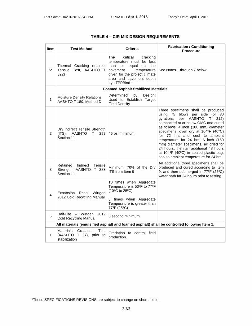
Last Saved: 04/01/2016 2:41 PM UPDATED Apr 1, 2016 Today’s Date: April 1, 2016
*These SPECIFICATIONS REVISIONS are subject to change on short notice.
3-63
TABLE 4 – CIR MIX DESIGN REQUIREMENTS
Item Test Method Criteria Fabrication / Conditioning
Procedure
5* Thermal Cracking (Indirect Tensile Test, AASHTO T 322)
The critical cracking temperature must be less than or equal to the pavement temperature given for the project climate area and pavement depth by LTPPBind
1.
See Notes 1 through 7 below.
Foamed Asphalt Stabilized Materials
1 Moisture Density Relations AASHTO T 180, Method D
Determined by Design; Used to Establish Target Field Density
2 Dry Indirect Tensile Strength (ITS), AASHTO T 283 Section 11
45 psi minimum
Three specimens shall be produced using 75 blows per side (or 30 gyrations per AASHTO T 312) compacted at or below OMC and cured as follows: 4 inch (100 mm) diameter specimens, oven dry at 104ºF (40°C) for 72 hrs and cool to ambient temperature for 24 hrs; 6 inch (150 mm) diameter specimens, air dried for 24 hours, then an additional 48 hours at 104ºF (40ºC) in sealed plastic bag, cool to ambient temperature for 24 hrs.
3 Retained Indirect Tensile Strength, AASHTO T 283 Section 11
Minimum, 70% of the Dry ITS from Item 9
An additional three specimens shall be produced and cured according to Item 9, and then submerged in 77ºF (25ºC) water bath for 24 hours prior to testing.
4 Expansion Ratio. Wirtgen 2012 Cold Recycling Manual
10 times when Aggregate Temperature is 50ºF to 77ºF (10ºC to 25ºC) 8 times when Aggregate Temperature is greater than 77ºF (25ºC)
5 Half-Life – Wirtgen 2012 Cold Recycling Manual
6 second minimum
All materials (emulsified asphalt and foamed asphalt) shall be controlled following Item 1.
1 Materials Gradation Test (AASHTO T 27), prior to stabilization
Gradation to control field production.

Last Saved: 04/01/2016 2:41 PM UPDATED Apr 1, 2016 Today’s Date: April 1, 2016
*These SPECIFICATIONS REVISIONS are subject to change on short notice.
3-64
TABLE 4 – CIR MIX DESIGN REQUIREMENTS
Item Test Method Criteria Fabrication / Conditioning
Procedure
Notes:
1. Specification temperature shall be chosen using current FHWA LTPPBind software, using the weather station closest to the project. The required temperature shall be the coldest temperature at the top of the recycled layer, using 98% reliability.
2. Samples shall be compacted to 150 mm (6 in.) diameter and at least 115 mm height, compacted to within 1% of design air voids at the design stabilizing agent content. Compacted samples shall be cured at 140ºF (60ºC) no less than 48 hours. Before testing, sample mass shall be checked every two hours until change in mass between successive checks does not exceed 0.05%. After curing, two specimens shall be saw-cut from each compacted sample to 50 mm (2 in.) in height. Perform bulk density testing after saw-cutting.
3. Three specimens are required at each of the three testing temperatures.
4. Select two testing temperatures that bracket the specification temperature above. For example, if the specification temperature is -13ºF (-25ºC), then two of the selected testing temperatures shall be -4ºF and -22ºF (-20ºC and -30ºC). A temperature of 14ºF or -40ºF (-10ºC or -40ºC) shall be used as the third testing temperature.
5. The tensile strength test shall be performed on each specimen directly after the tensile creep test (at the same temperature as the creep test).
6. The critical cracking temperature is defined as the temperature at the intersection of the thermal stress curve (derived from the creep data) and the tensile strength line (the line connecting the average tensile strengths at the three testing temperatures).
7. To meet this specification, the critical cracking temperature predicted by the Indirect Tensile Test must be less than or equal to the pavement temperature given for the project climate area and pavement depth by LTPPBind.
V. EQUIPMENT
1. CIR – The CIR work shall be completed with a self-propelled machine with a down cutting
milling head that is capable of pulverizing and recycling the existing asphalt concrete pavement to a maximum depth of 6 inches, uniformly incorporating the stabilizing agent(s) and water, and mixing the materials to produce a homogeneous product. The machine shall be capable of pulverizing and recycling the full lane width in no more than two passes (with the longitudinal joint located between the anticipated wheel paths). The machine shall have the ability to meter dosage rates for stabilizing agent(s) and water relative to the machine’s ground speed. Individual valves on the spray bar shall be capable of being turned off as necessary to minimize stabilizing agent(s) and water overlap on subsequent passes. The equipment shall be operated in accordance with the manufacturers’ recommendations.
The self-propelled machine may also have a screed attached to the milling and mixing unit. The screed shall have slope control and the ability to convey material out to the side of the screed if there is a surge of material between the mixing chamber and the screed. The mixing unit and screed combination must have electronic grade controls. In lieu of a screed attachment, the material may be placed into an asphalt paver that meets the requirements of Section 315.03(b) of the Specifications by means of a material transfer device.
Any additives such as water, lime slurry, etc. added by the equipment at the milling head or mixing unit shall be controlled through liquid metering devices capable of automatically

Last Saved: 04/01/2016 2:41 PM UPDATED Apr 1, 2016 Today’s Date: April 1, 2016
*These SPECIFICATIONS REVISIONS are subject to change on short notice.
3-65
adjusting for the variation in bituminous material going into the mixing unit, by means of weighing device or proportional control systems.
The metering devices shall be capable of delivering the amount of additive to within +/- 0.2 percent of the required amount, except that a capability of adding up to 5 percent water by weight of the pulverized bituminous material is mandatory. The Department will not require metering of the water added at the milling machine to control dust in the screens, belts, or crusher/material sizing unit.
A pozzolonic material distributor truck shall be used if dry stabilizing agents is/are applied directly to the asphalt concrete pavement prior to CIR operations. The pozzolonic material distributor truck shall have the ability to uniformly apply the stabilizing agent(s) at the specified rate.
2. Rollers – All rollers shall be self-propelled. At least one pneumatic tire roller shall have a
minimum gross operating weight of not less than 50,000 lbs. At least one double steel-wheeled vibratory roller shall have a gross operating weight of not less than 24,000 lbs. and a width of 78 inches. All rollers must have properly working scrapers and water spraying systems.
VI. Test Strip
Before planned start of full production, stabilize a 2,500 foot long test strip, one-lane wide, at the designated thickness and designed optimal stabilizing agent(s) content provided in the approved job mix design. Construct the test strip on the project at an approved location, using construction procedures intended for the entire project. Cease production after construction of the test strip until the test strip is evaluated and accepted. Test strip acceptance will be determined in accordance with Section VII below. The test strip shall be considered a lot and payment will follow the payment tables established in this Special Provision.
VII. CONSTRUCTION METHODS 1. Grass and other vegetation shall be removed from the edge of the existing pavement to
prevent contamination of the pulverized asphalt concrete material during the milling operation.
2. The existing asphalt concrete pavement shall be milled to the required depth and width as
indicated on the plans. Recycling shall be performed in a manner that minimizes disturbance of the underlying material in the existing roadway. The milling operation shall be conducted so that the amount of fines occurring along the vertical faces of the cut shall not prevent bonding of the CIR materials. If needed, the CIR materials shall be processed by crushing or sizing to the required gradation specified in TABLE 3. When a paving fabric is encountered during the CIR operation, the Contractor shall make the necessary adjustments in equipment or operations so that at least ninety percent (90 percent) of the shredded fabric in the recycled material is no more than the particle size specified in TABLE 3 herein. These changes may include, but shall not be limited to: adjusting the forward machine speed, milling rate, the milling depth, and/or adding or removing screens in order to obtain the specified recycled material. The Contractor will be required to waste material containing over-sized pieces of paving fabric as directed by the Engineer. The Contractor will not receive additional payment for the necessary adjustments to his equipment or CIR operations to accommodate the presence and processing of the paving fabric.
3. Adjacent CIR passes shall overlap by a minimum 4 inches. The stabilizing agent shall be
controlled such that it is not applied at the joint overlap location more than the dosage rate in the approved mix design by the total of the passes.
Last Saved: 04/01/2016 2:41 PM UPDATED Apr 1, 2016 Today’s Date: April 1, 2016
*These SPECIFICATIONS REVISIONS are subject to change on short notice.
3-66
4. Compaction of the recycled mix shall be completed using rollers meeting the requirements of
Section V-3herein. The Contractor shall establish rolling patterns to achieve the density target as determined by nuclear density testing. Final rolling to eliminate pneumatic tire marks and to achieve density shall be done by double drum steel roller(s), either operating in a static, oscillating or vibratory mode. Oscillating and vibratory mode should only be used if it is shown to not damage the pavement. Rolling shall be performed until the material reaches a density of 98 percent the maximum theoretical density as measured via a nuclear density gauge. Rolling shall start no more than 30 minutes after initiation of paving. Finish rolling shall be completed no more than one hour after paving is completed, unless otherwise approved by the Engineer. When possible, rolling shall not be started or stopped on uncompacted material but performed with rolling patterns established so that they begin or end on previously compacted material or the existing pavement.
5. After compaction of the recycled material, a fog seal shall be applied to the recycled surface
at a uniform application rate of 0.06 gal/sy (0.04 gal/sy residual). The fog seal shall be a CSS-1h, CQS-1h, or Non Tracking Tack Coat conforming to the requirements of Section 210 of the Specifications and the Special Provision For Nontracking Tack Coat included in the Contract. A light grit conforming to Section 202, Grading A, shall be applied to reduce raveling. After fog sealing, no traffic, including the Contractor’s equipment, will be permitted on the completed recycled material until the water content of the CIR material is a maximum of 50 percent of the optimum water content in accordance with paragraph 7 below. After this “curing” period, rolling traffic may be permitted on the recycled material. This time may be adjusted by the Engineer to allow establishment of sufficient cure so traffic will not initiate raveling. After opening to traffic, the surface of the recycled pavement shall be maintained in a condition suitable for the safe movement of traffic. All loose particles that may develop on the pavement surface shall be removed without damaging the surface.
6. Any damage to the completed CIR material, such as raveling or other surface imperfections,
shall be repaired by the Contractor at their expense, to the Engineer’s satisfaction in accordance with Section 105.14, prior to the placement of the asphalt concrete surface course(s), or other applicable surface treatment.
7. Before placing the asphalt concrete surface courses, or other applicable surface treatment,
the CIR material shall be allowed to cure until the moisture of the material is a maximum of 50 percent of the optimum water content or until approval of the Engineer is received. Moisture content shall be measured per AASHTO T 329 on samples taken from two stratified random locations and immediately placed in a sealed plastic bag, as determined by the Engineer for each production day. Other methods and sampling rates may be used if supplied in the Contractor’s Quality Control Plan and approved by the Engineer. Split samples may be taken at the direction of the Engineer. A tack coat, in accordance with the Special Provision for Nontracking Tack Coat, shall be applied prior to any additional asphalt layers.
VIII. ACCEPTANCE TESTING
1. Field Compaction – A nuclear density gauge conforming to the requirements of VTM-10
shall be used for determining mat density by the Direct Transmission method. The Contractor’s nuclear density gauge shall have been calibrated within the previous 12 months by an approved calibration service. In addition, the Contractor shall maintain documentation of such calibration service for the 12-month period from the date of the calibration service and furnish the same to the Engineer if requested. The Contractor shall determine a roller pattern and construct a control strip in accordance with the requirements of VTM 10. Density test locations shall be marked and labeled by the Contractor in accordance with the requirements of VTM-76. The control strip will be acceptable if the field proctor (AASHTO T 180, Method

Last Saved: 04/01/2016 2:41 PM UPDATED Apr 1, 2016 Today’s Date: April 1, 2016
*These SPECIFICATIONS REVISIONS are subject to change on short notice.
3-67
D) is at least 98 percent of the target density from the approved job mix designs. The required density of the compacted CIR course shall not be less than 98.0 percent of the target density from the approved job mix designs.
2. Test section (lot) – For the purposes of acceptance, each day’s production will be
considered a lot unless the paving length is less than 3,000 linear feet or greater than 7,500 linear feet. When paving is less than 3,000 feet, it shall be combined with the previous day’s production or added to the next day’s production to create a lot as described below.
The standard size of a lot shall be 5,000 linear feet, with 1,000 linear foot sublots, of any pass 6 feet or greater made by the paving train for the thickness of the course. If the Engineer approves, the lot size may be increased to 7,500 linear foot lots with five 1,500 foot sublots when the Contractor’s normal daily production exceeds 7,500 feet. When a partial lot occurs at the end of a day’s production or upon completion of the project, the lot shall be either added to the previous lot if the partial lot contains one or two complete sublots or redefined to be an entire lot if the partial lot contains three or four complete sublots.
Each lot shall be tested for density by taking a nuclear density reading from two random test sites selected by the Engineer within each sublot used for acceptance. Test sites shall not be located within 18 inches of the edge of any application width for CIR mixes.
The average of the sublot density measurements will be compared to the target nuclear density established by the approved mix design to determine the acceptability of the lot. Once the average density of the lot has been determined, the Contractor will not be permitted to provide additional compaction to raise the average. If two consecutive sublots produce density results less than 98 percent of the target density, the Contractor shall immediately notify the Engineer and institute corrective action. By the end of the day’s operations, the Contractor shall furnish the test data developed during the day’s recycling to the Engineer. The Contractor shall verify their results for every lot by performing a field proctor (AASHTO T180, Method D). The field proctor shall be at least 98 percent of the target density from the approved mix design.
The tonnage or square yards of each lot will be based on the lot’s width and length and the mixture application rate as designated in the Contract or as revised by the Engineer. Payment will be made in accordance with the requirements of TABLE 5. Percent of Payment will be calculated based on the Cold In-Place Recycling (CIR) (Depth), Liquid Asphalt (Emulsion) and Liquid Asphalt (Foamed).
TABLE 5 - PAYMENT SCHEDULE FOR LOT DENSITIES
% of Target Control Strip Density % of Payment
98.0 or greater 100
97.0 to less than 98.0 95
96.0 to less than 97.0 90
Less than 96.0 75
3. Gradation – For CIR, the Contractor shall verify that the unstabilized gradation conforms to
the JMF at the beginning of each production day and wherever there are changes in the pavement structure being recycled. Gradation bands shall be established for the day by operating the machine at two distinct forward speeds and sampling the associated unstabilized material for field gradation testing.
4. Depth Check – Depth checks shall be performed by the Contractor in accordance with VTM-
38, Method B at a minimum rate of twice per 5,000 linear feet after compaction. Depth

Last Saved: 04/01/2016 2:41 PM UPDATED Apr 1, 2016 Today’s Date: April 1, 2016
*These SPECIFICATIONS REVISIONS are subject to change on short notice.
3-68
checks shall be taken at the Engineer’s direction. In the event that a slit trench cannot be created in accordance with VTM-38, Method B, the contractor may remove the CIR materials by use of a core rig and depth measurements taken in accordance with VTM-38, Method B.
Acceptance of CIR course for depth will be based on the mean result of measurements of samples taken from each lot of material placed.
A lot will be considered acceptable for depth if the mean result of the tests is within the tolerance of the plan depth for the number of tests taken as shown in TABLE 6.
TABLE 6 – PROCESS TOLERANCE FOR DEPTH CHECKS
Plan Depth, inches Tolerance, inches (Plus or Minus)
2 tests 3 tests 4 tests
≤ 4 0.45 0.35 0.30
>4 ≤ 6 0.65 0.50 0.40
If the mean depth of a lot of material is in excess of the tolerance, the Contractor will not be paid for that material in excess of the tolerance for the plan depth specified throughout the length and width of the lot of material represented by the tests. For excessive depth CIR courses, the rate of deduction from the square yardage allowed for payment as CIR course will be calculated by prorating the mean depth measured based on the plan depth specified or the Department can require excessive material to be removed at the Contractor’s expense.
If the mean depth of a lot of material is deficient by more than the allowable tolerance for the plan depth specified, correction will be required and the Contractor will be paid for the quantity of material that has been placed in the lot. For sections of CIR course that are deficient in depth beyond the tolerance, the Contractor shall furnish and place material specified for the subsequent course or as approved by the Engineer to bring the deficient CIR course depth within the tolerance of the specified plan depth. This additional material shall be placed at the Contractor’s expense.
5. Stabilizing Agent Dosage Rate – The Contractor shall verify the stabilizing agent dosage
rate by reading a calibrated meter ten times per lot. The dosage rate shall be within 0.20 percentage points of the approved JMF. If the dosage rate is outside 0.20 percentage points, then paving/production shall stop and the Contractor shall take corrective measures to bring the dosage rate within tolerance. The Engineer will calculate the yield at the end of each production day.
6. Construction Records – The Contractor shall prepare separate test reports meeting the
requirements of AASHTO R 18 or may use the current appropriate VDOT forms. Records documenting the dosage rate of stabilizing agent(s) and other test results from TABLE 4 shall be provided to the Engineer, unless specified otherwise.
IX. WEATHER LIMITATIONS
Recycling operations shall be completed when both the atmospheric temperature and material to be processed (measured in the shade and away from artificial heat) is a minimum 50°F. The weather forecast shall not call for freezing temperatures within 48 hours after placement of CIR on any portion of the project.
X. MEASUREMENT AND PAYMENT

Last Saved: 04/01/2016 2:41 PM UPDATED Apr 1, 2016 Today’s Date: April 1, 2016
*These SPECIFICATIONS REVISIONS are subject to change on short notice.
3-69
Cold In-Place Recycling (CIR) will be measured by the square yard of the completed sections for the depth specified in the plans and will be paid for at the Contract unit price per square yard of depth. This price shall be full compensation for removal and processing of the existing pavement; preparing, hauling, and placing of all materials; furnishing stabilizing agents, fog seal, grit and additives (including all freight involved); for all manipulations, including removal of grass and other vegetation, rolling and brooming; testing and documentation; asphalt supplier services; and for all labor, tools, equipment and incidentals necessary to complete the work. Liquid Asphalt (Emulsion) will be measured and paid for at the Contract unit price per ton. This price shall be full compensation for furnishing and incorporating the emulsion into the mixture. An emulsion content of 2.5 percent by weight of the milled bituminous material shall be used for bidding purposes prior to the approved mix design. The actual emulsion content will be adjusted based on the quantity necessary to meet the design requirements in TABLE 4. Liquid Asphalt (Foamed) will be measured and paid for at the Contract unit price per ton. This price shall be full compensation for furnishing and incorporating the foamed asphalt into the mixture. A foamed asphalt content of 2.5 percent by weight of the milled bituminous material shall be used for bidding purposes prior to the approved mix design. The actual foamed asphalt content will be adjusted based on the quantity necessary to meet the design requirements in TABLE 4. Payment will be made under:
Pay Item
Pay Unit
Cold In-Place Recycling (CIR) (Depth) Square Yard
Liquid Asphalt (Emulsion) Ton
Liquid Asphalt (Foamed) Ton
Additional Crushed RAP if required to meet the contract requirements will be measured and paid for at $ fill in amount per ton. This price shall be full compensation for furnishing and incorporating the additional RAP into the mixture. The additional RAP must meet the requirements of Section II-5 herein for payment purposes. Additional Aggregate, if required, in accordance with the JMF and other contract requirements, will be measured and paid for at $ fill in amount per ton. This price shall be full compensation for furnishing and incorporating the additional aggregate material into the mixture. The additional aggregate material must meet the requirements of Section II-6 herein for payment purposes.

Last Saved: 04/01/2016 2:41 PM UPDATED Apr 1, 2016 Today’s Date: April 1, 2016
*These SPECIFICATIONS REVISIONS are subject to change on short notice.
3-70
GUIDELINES – USE WHEN REQUESTED BY THE DESIGNER FOR ASPHALT PROJECTS.
S315AD0-1215
VIRGINIA DEPARTMENT OF TRANSPORTATION SPECIAL PROVISION FOR
FULL-DEPTH RECLAMATION (FDR)
August 7, 2015
I. DESCRIPTION
Full-depth reclamation (FDR) is defined as those processes in which all of the asphalt pavement layers
and some portion of the underlying bound and unbound layers are pulverized, stabilized, and compacted in place. This is most commonly performed using hydraulic cement, lime, foamed asphalt or asphalt emulsion as the primary stabilizing additives.
The Contractor shall furnish all labor, materials, and equipment required for completing the work. The
Contractor shall select the final mix design (job mix formula- JMF) and construction methods to meet the performance requirements specified herein.
II. MATERIALS
Stabilizing Agent(s) – The amount of stabilizing agents to be used shall be determined by the Contractor by means of a mixture design process. Hydraulic cement shall conform to the requirements of Section 214 of the Specifications. Lime shall conform to the requirements of Section 240 of the Specifications. Fly ash shall conform to the requirements of Section 241 of the Specifications. All liquid asphalts used for stabilizing agents shall be emulsions and PG binders on the VDOT Approved List for emulsions and PG binders, Approved List 50 and 50.1. Liquid asphalts not currently on the Approved List shall be submitted to VDOT for approval. Asphalt emulsions shall conform to the requirements of Section 210 of the Specifications; liquid asphalts shall meet the requirements of Section 211.02 (a) of the Specifications.
1. Water – Any water used for mixing shall meet the requirements of Section 216 of the
Specifications.
2. FDR – The FDR material shall have 100% of all particles passing the 2.0 inch (50mm) sieve size and 55% of all particles passing the 3/8 inch (9.5mm) sieve size prior to the addition of any stabilizing agents.
3. Other Additives – If necessary, additional additives may be used by the Contractor to meet the
requirements in TABLE 4. In the case where an additional additive is used, the type and dosage
must be described in the JMF’s submitted to the Engineer. For FDR using asphalt emulsion,
hydrated lime shall be added according to the requirements in Section 211.02(i) of the
Specifications.
4. Addition of Crushed Reclaimed Asphalt Pavement (RAP) Material – RAP material may be
added by the Contractor and shall meet the requirements of Section 211.02(j) of the Specifications
and TABLE 1.
TABLE 1 – ADDITIONAL CRUSHED RAP

Last Saved: 04/01/2016 2:41 PM UPDATED Apr 1, 2016 Today’s Date: April 1, 2016
*These SPECIFICATIONS REVISIONS are subject to change on short notice.
3-71
5. Additional aggregate – Based on the results of the mixture design or other requirements, the
Contractor shall determine if additional aggregate is required. If the Contractor determines
additional aggregate is required any additional aggregate shall meet Section 203 of the
Specifications and the requirements in TABLE 2, and it shall produce a product which meets the
mixture requirements given in TABLE 4 and final mix gradation specified in Section IV-1.
TABLE 2 – ADDITIONAL AGGREGATE
6. Handling and Storage – Store cement to prevent moisture degradation and partial hydration. Do
not use cement that has become hard, caked or lumpy. Store aggregates and RAP so that segregation and inclusion of foreign materials are prevented. Do not use the bottom six (6) inches of aggregate or RAP piles in contact with the ground.
III. QUALITY CONTROL PLAN
The Contractor shall also be responsible for developing and implementing a Quality Control Plan to ensure that operational techniques and activities provide integral and finished material of acceptable quality. Contractor sampling and testing shall be performed to control the processes and ensure material compliance with the requirements of the Contract. The Contractor shall provide their Quality Control Plan and Job Mix Formulae to the District Materials Engineer for approval no less than 30 calendar days prior to the start of FDR operations.
For each FDR project, the Contractor is required to furnish a project specific Quality
Control Plan that shall include, at a minimum, the following information: 1. A description of the Contractor’s Quality Control organization, including the number of full-time
equivalent employees or Sub-Contractors with specific Quality Control responsibilities, including an organizational chart showing lines of authority and reporting responsibilities
2. A listing by discipline with the name, qualifications, duties, responsibilities and authorities for all persons proposed to be responsible for Construction Quality Control
3. A Quality Control Sampling, Testing and Analysis Plan with methods that include a description of how random locations for testing and sampling are determined
4. Identification and description of qualifications of the laboratory(s) to be used for each type of testing
5. Specific listing of documentation for Quality Control activities
Tests
Method
Limit
Deleterious Materials: Clay Lumps and Friable Particles in Aggregate
AASHTO T 112 0.2% maximum
Maximum Sieve size, 2.0 in. (50 mm) AASHTO T 27 100% passing
Tests
Method
Limit
Los Angeles Abrasion Value AASHTO T 96 45% maximum loss
Sand Equivalent AASHTO T 176 45% minimum
Maximum size, 100% Passing, Sieve Size AASHTO T 27 2.0 in. (50 mm)
Water absorption AASHTO T 85 3% maximum

Last Saved: 04/01/2016 2:41 PM UPDATED Apr 1, 2016 Today’s Date: April 1, 2016
*These SPECIFICATIONS REVISIONS are subject to change on short notice.
3-72
6. Procedures to meet contract requirements for corrective action when Quality Control criteria are not met
7. Procedures to protect stabilized material from receiving excessive moisture from weather events (i.e. rain, fog, etc.) and corrective actions when criteria are not met
8. Contingency Plan including but not limited to:
Inclement weather
Equipment breakdowns
Materials shortages
Excessive fluff - (greater than approximately 10%). Fluff is defined as the increase in material thickness of the recycled layer over the specified recycling depth due to remixing in place.
Deficient density of installed FDR
Material doesn’t break or cure in timely manner
Gradation is outside tolerance(s)
Production modifications based on changes in ambient and/or material temperature.
The Contractor shall have a technical representative at the project site during the mixing and placement operations for the trial section and first day of production. At a minimum, this person must:
Have 2 years minimum experience with the FDR process
Have personally supervised a minimum of 5 successful FDR projects
Have personal experience in developing FDR mix designs
Have the experience to perform and supervise field process control testing
Submit a list of references, with current telephone numbers, who are able to verify the experience required herein
The Contractor may use consultants or manufacturers’ representatives to satisfy the requirements of this section provided they meet the requirements above and are on-site or available for contact while construction operations are being performed.
IV. Job Mix Formula (JMF)
1. Mixture Designs – FDR mix designs in the form of a job-mix formula (JMF) shall be submitted to
the Engineer for the Department’s approval no less than 30 calendar days prior to the start of
FDR operations. More than one JMF may be required. The gradation of each JMF shall fall
within the bands shown below.
TABLE 3 - DESIGN RANGE

Last Saved: 04/01/2016 2:41 PM UPDATED Apr 1, 2016 Today’s Date: April 1, 2016
*These SPECIFICATIONS REVISIONS are subject to change on short notice.
3-73
Sieve Size
Percentage by Weight Passing
Square Mesh Sieves (in)
Lower Upper
2.0” 100 100
3/8” 55 --
The Contractor shall obtain sufficient samples of the material to be reclaimed directly from each roadway within the project for laboratory testing and mix design analysis. Samples shall be obtained from every 2500 linear feet, within each lane and to the proposed total recycling depth, with a minimum of six locations for each mix design. Sample locations from each lane may be offset or adjacent from each other. Additional locations may also be selected based on pavement conditions and variability.
2. Mixture Designs Submittal – The design shall be performed by the Contractor in accordance
with these specifications and submitted to the Engineer for approval (30) working days prior to the planned start of the work. The mix design submittal shall include, at a minimum, the following information:
A. Target field density
B. Percent by weight of all stabilizing agents to be added to the recycled mix
C. Percent water content (at room temperature) required
D. Expansion ratio and half-life characteristics and temperature of asphalt binder at the time of
injection into foaming chamber (for mixtures using foamed asphalt)
E. Minimum curing time/set time for the asphalt emulsion
F. Temperature of asphalt emulsion at the time of incorporating into the mixture (for mixtures
using asphalt emulsion)
G. Target gradation (including any aggregate to be added)
TABLE 4 – FULL-DEPTH RECLAMATION MIX DESIGN REQUIREMENTS
Test
Test Method
Criteria
Liquid Limit, Plastic Limit, and Plasticity Index of Soil
VTM-7 Report
Dry Preparation and Mechanical Analysis of Soils, Select Material, Subbase and Aggregate Bases
VTM-25 Report
Classification of Soils AASHTO M 145 Report
Moisture-Density Relations of Soil-Cement Mixtures
AASHTO T 134 Report
Moisture Density Relations for Bituminous Stabilizing Agents
AASHTO T 180 Report
Compressive Strength of Soil-Cement Cylinders ASTM D 1633 Min. 250 psi (Max. 450 psi) at seven (7) days
Determining the Strength of Soil-Lime Mixtures VTM-11 Min. 150 psi
Dry Indirect Tensile Strength (ITS) for Foamed Asphalt Stabilizing Agent
AASHTO T 283 Section 11*
45 psi minimum
Last Saved: 04/01/2016 2:41 PM UPDATED Apr 1, 2016 Today’s Date: April 1, 2016
*These SPECIFICATIONS REVISIONS are subject to change on short notice.
3-74
Marshall Stability Test for Asphalt Emulsion Stabilizing Agent
ASTM 5581 (6 inch specimens), AASHTO T 245 (4 inch specimens)**
2500 lbs minimum (6 inch (150mm) diameter specimen), or 1250 lbs (4 inch (100mm) diameter specimen)
* Three specimens shall be produced using either 75 blows per side (per VTM-57) or 30 gyrations (per AASHTO T 312) compacted at or below Optimum Moisture Content and cured as follows: 4 inch (100 mm) diameter specimens, oven dry at 104ºF (40°C) for 72 hrs and cool to ambient air temperature for 24 hrs; 6 inch (150 mm) diameter specimens, air dried for 24 hours, then an additional 48 hours at 104ºF (40ºC) in sealed plastic bag, cool to ambient air temperature for 24 hrs. ** Three specimens shall be produced at 75 blows per side (or 30 gyrations per AASHTO T 312) and cured at 140ºF (60°C) to constant mass, hold specimens at 104ºF (40°C) for 2 hours in a forced draft oven immediately prior to testing.
If a change in source materials is made during construction, a new JMF’s shall be created and
approved by the Engineer prior to use on the project. The JMF’s shall meet the above criteria at the
approved stabilizing agents content.
V. EQUIPMENT
1. Pulverizing – The equipment used to reclaim existing pavements shall be capable of pulverizing existing pavement, as well as any additional materials, to meet the gradation provided in the approved job mix design, for the widths provided in the Plans, to the depth specified in the approved pavement design.
2. Stabilizing – The equipment used to stabilize the pulverized materials shall be capable of incorporating the stabilizing agents at the rate provided in the approved job mix design, automatically metering dosage and mixing the full depth and width of pulverized material to a homogenous mixture.
3. Grading – The equipment used to grade the stabilized material shall be capable of working within the constraints of the excavation and grading the full width of stabilized material in conformity with the lines and grades provided in the Plans.
4. Compacting – The equipment used to compact the stabilized material shall be capable of working within the constraints of the excavation and compacting the stabilized material in conformity with the lines and grades provided in the Plans, as well as in conformity with the density requirements provided in the approved job mix design.
VI. TRIAL SECTION
One week before planned start of full production, stabilize a 2,500 foot long trial section, one-lane wide, at the designated thickness and designed optimal stabilizing agents content provided in the approved job mix design. Construct the trial section on the project at an approved location. Construct the trial section using construction procedures intended for the entire project. Cease production after construction of the trial section until the trial section is evaluated and accepted by the Engineer. The trial section shall be considered a lot and payment will follow the payment tables established in this specification.
VII. CONSTRUCTION METHODS

Last Saved: 04/01/2016 2:41 PM UPDATED Apr 1, 2016 Today’s Date: April 1, 2016
*These SPECIFICATIONS REVISIONS are subject to change on short notice.
3-75
1. Grass and Other Vegetation – All grass and other vegetation shall be removed from the edge of
the existing pavement to prevent contamination of the pulverized bituminous material during the
milling operation.
2. FDR – Recycling shall be performed to the depth provided in the plans, while incorporating stabilizing
agents, mineral filler, additional aggregate and water. Mixing shall continue until, and the speed of the recycling unit adjusted to ensure, a homogenous mixture of the above materials and pulverized materials is achieved. A. Pre-cutting, grading and light compacting of the recycled material shall be performed prior to
incorporation of the stabilizing agent.
B. The application rate of all stabilizing agents shall be continuously monitored using calibrated, automatic meters. The application rate shall be within 0.20 percentage points of the optimal stabilizing agents content provided in the approved job mix design. If the measured application rate falls outside the above tolerance, then the recycling operations shall be stopped and corrected before proceeding.
C. The water content of the stabilized material shall be monitored closely to ensure conformance with the approved job mix design within ± 2 percentage points of optimum and to ensure proper compaction.
D. Longitudinal joints between adjacent stabilization passes shall be overlapped at least 4 inches. Transverse joints created by the recycling process shall be saw-cut, if necessary, to provide a vertical, clean face to ensure proper compaction.
3. Final Grading and Compacting – The final grading and compacting shall be performed within the
constraints of the excavation and the stabilized material shall be compacted in conformity with the lines and grades provided in the Plans. Compaction shall progress across the full width of the stabilized area until maximum density is achieved.
A. Once the entire working width (full lane width plus affected shoulder width) has been stabilized,
and only after primary compaction has been completed, the entire working width shall be graded to the required profile and cross-slope. Disturbance to the stabilized and primarily compacted material shall be kept to a minimum during this grading and shaping operation.
B. Any additional water required to achieve maximum density shall be applied by spraying the surface of the stabilized material with light applications. Care shall be taken not to over-apply additional water to any areas of stabilized material.
4. Surfacing – The surface of the compacted material shall be kept moist until covered with an asphalt-
based layer in the case of cement stabilized materials. For bituminous stabilized materials, the FDR shall be allowed to cure until the moisture of the material is a maximum of 50% the optimum moisture content or until approval of the Engineer is received. Subsequent asphalt-based layers can be placed any time after finishing, as long as the FDR is sufficiently able to support the required construction equipment without marring or permanent distortion of the surface.
VIII. ACCEPTANCE TESTING
1. Field Compaction – Density shall be determined with a nuclear gauge operating in direct
transmission mode conforming to the requirements of VTM-10 to the full depth of the FDR layer. The Contractor shall have had the gauge calibrated within the previous 12 months by an approved calibration service. In addition, the Contractor shall maintain documentation of such calibration service for the 12-month period from the date of the calibration service.

Last Saved: 04/01/2016 2:41 PM UPDATED Apr 1, 2016 Today’s Date: April 1, 2016
*These SPECIFICATIONS REVISIONS are subject to change on short notice.
3-76
The project will be divided into lots by the Engineer for the purpose of defining areas represented by each series of tests.
2. Lot – For the purposes of acceptance, each day’s production shall be considered a lot unless the
paving length is less than 3,000 linear feet or greater than 7,500 linear feet. When paving is less than 3,000 feet, it shall be combined with the previous day’s production or added to the next day’s production to create a lot as described below.
For the purposes of acceptance, the standard size of a lot shall be 5,000 linear feet, with 1,000 foot sublots, the full width of the lane (including any affected shoulder width). If the Engineer approves, the lot size may be increased to 7,500 linear foot lots with five 1,500 foot sublots when the Contractor’s normal daily production exceeds 7,500 feet. When a partial lot occurs at the end of a day’s production or upon completion of the project, the lot shall be either added to the previous lot if the partial lot contains one or two complete sublots, or redefined to be an entire lot if the partial lot contains three or four complete sublots.
Each lot shall be tested for density by taking a nuclear density reading from two stratified-random test sites selected by the Engineer within each sublot. Test sites shall not be located within 18 inches of any longitudinal joint.
The average of the sublot density measurements will be compared to the maximum density from the approved mix design to determine the acceptability of the lot. Once the average density of the lot has been determined, the Contractor will not be permitted to provide additional compaction to raise the average. If two consecutive sublots produce density results less than 97.0 percent of the target density, the Contractor shall immediately notify the Engineer and institute corrective action. By the end of the day’s operations, the Contractor shall furnish the test data developed during the day’s production to the Engineer.
Payment will be made in accordance with the requirements of TABLE 5.
3. Depth Check – Depth checks shall be performed by the Contractor twice per lot after compaction and prior to the placement of the next pavement layer. The depth checks shall be performed twice per lot following VTM-38, Method B. Acceptance testing of FDR for depth will be based on the mean result of measurements of samples taken from each lot of material placed. A lot will be considered acceptable for depth if the mean result of the tests is within the tolerance of the plan depth for the number of tests taken as shown in TABLE 6.
TABLE 6 – PROCESS TOLERANCE FOR DEPTH CHECKS
Plan Depth, inches Tolerance, inches (Plus or Minus)
1 test 2 tests 3 tests 4 tests
TABLE 5 - PAYMENT SCHEDULE FOR LOT DENSITIES
% of Density from Approved Mix Design
% of Payment
97.0 or greater 100
96.0 to less than 97.0 95
95.0 to less than 96.0 90
Less than 95.0 75

Last Saved: 04/01/2016 2:41 PM UPDATED Apr 1, 2016 Today’s Date: April 1, 2016
*These SPECIFICATIONS REVISIONS are subject to change on short notice.
3-77
>6 ≤ 8 0.9 0.65 0.5 0.4
>8 ≤ 12 1 0.9 0.7 0.5
>12 1.2 1 0.8 0.6
If an individual depth test is in excess of the tolerance for one test, that portion of the lot represented by that test will be excluded from the lot. If an individual test result indicates that the depth of material represented by the test is more than the tolerance for one test, the Contractor will not be paid for that amount of material in excess of the tolerance throughout the length and width represented by the test. If an individual test result indicates that the depth of the material represented by the test is deficient by more than the tolerance for one test, correction of the base course represented by that test shall be made by the Contractor as specified hereinafter. If the mean depth of a lot of material is in excess of the tolerance, the Contractor will not be paid for that amount of material throughout the length and width represented by the tests. The Department can require excessive material to be removed at the Contractor’s expense. If the mean depth of a lot of material is deficient beyond the allowable tolerance, correction will be required and the Contractor will be paid for the quantity of material that has been placed in the lot. The Contractor will be required to furnish and place material specified for the subsequent course to bring the deficient FDR course depth within the tolerance. This additional material will be placed at the Contractor’s expense.
4. Gradation – The Contractor will check the unstabilized gradation twice per day.
5. Stabilizing Agent Dosage Rate – Contractor shall verify the dosage rate ten times per lot. The dosage rate shall be within 0.20 percentage points of the approved mix design. If the dosage rate is beyond this tolerance, then paving shall stop and the contractor shall take corrective measures.
6. Construction Records – The Contractor shall prepare separate test reports meeting the requirements of AASHTO R 18 or may use the current appropriate VDOT forms. Records documenting the dosage rate of stabilizing agents and other test results from Table 4 shall be provided to the Engineer, unless specified otherwise.
IX. WEATHER LIMITATIONS
Recycling operations shall be completed when both the atmospheric temperature and material to be processed (measured in the shade and away from artificial heat) is a minimum 40°F (4 °C). The weather forecast shall not call for freezing temperature within 48 hours after placement of any portion of the project.
X. MEASUREMENT AND PAYMENT
Full Depth Recycling (FDR) will be measured by the square yard of the completed sections for the depth specified in the plans and paid for at the Contract unit price per square yard of depth. This price shall be full compensation for removal and processing of the existing pavement; for preparing, hauling, and placing all materials; furnishing additives (not including stabilizing agents); for all freight involved; for all manipulations, including removal of grass and other vegetation; rolling and brooming; testing and documentation; stabilizing agent supplier services; and for all labor, tools, equipment and incidentals necessary to complete the work. Stabilizing agents will be paid as follows:

Last Saved: 04/01/2016 2:41 PM UPDATED Apr 1, 2016 Today’s Date: April 1, 2016
*These SPECIFICATIONS REVISIONS are subject to change on short notice.
3-78
Liquid Asphalt (Emulsion) will be paid for at the Contract unit price per ton. This price shall be full compensation for furnishing and incorporating the emulsion into the mixture. An emulsion content of 3.0% by weight of the reclaimed material shall be used for bidding purposes prior to the completed design. The actual emulsion content will be adjusted based on the quantity necessary to meet the design requirements in Table 4.
Liquid Asphalt (foamed) will be paid for at the Contract unit price per ton. This price shall be full compensation for furnishing and incorporating the foamed asphalt into the mixture. A foamed asphalt content of 2.5% by weight of the reclaimed material shall be used for bidding purposes prior to the completed mix design. The actual foamed asphalt content will be adjusted based on the quantity necessary to meet the design requirements in Table 4.
Hydraulic Cement will be paid for at the Contract unit price per ton. This price shall be full compensation for furnishing and incorporating the hydraulic cement into the mixture. A cement content of 5.0% by weight of the reclaimed material shall be used for bidding purposes prior to the completed design. The actual cement content will be adjusted based on the quantity necessary to meet the design requirements in Table 4.
Lime will be paid for at the Contract unit price per ton. This price shall be full compensation for furnishing and incorporating the lime into the mixture. A lime content of 5.0% by weight of the reclaimed material shall be used for bidding purposes prior to the completed design. The actual lime content will be adjusted based on the quantity necessary to meet the design requirements in Table 4. Other Cementitious Material will be paid for at the Contract unit price per ton. This price shall be full compensation for furnishing and incorporating the cementitious into the mixture. A cementitious content of 5.0% by weight of the reclaimed material shall be used for bidding purposes prior to the completed design. The actual cementitious content will be adjusted based on the quantity necessary to meet the design requirements in Table 4. Payment will be made under:
Pay Item Pay Unit Full-Depth Reclamation (Depth) Square Yard Liquid Asphalt (Emulsion) Ton Liquid Asphalt (Foamed) Ton Hydraulic Cement Ton Lime Ton Other Stabilizing Materials Ton
Additional Crushed RAP if required to meet the contract requirements will be measured and paid for at $ fill in amount per ton. This price shall be full compensation for furnishing and incorporating the additional RAP into the mixture. The additional RAP must meet the requirements of Section II-4 herein for payment purposes. Additional Aggregate, if required, in accordance with the JMF and other contract requirements, will be measured and paid for at $ fill in amount per ton. This price shall be full compensation for furnishing and incorporating the additional aggregate material into the mixture. The additional aggregate material must meet the requirements of Section II-5 herein for payment purposes.

Last Saved: 04/01/2016 2:41 PM UPDATED Apr 1, 2016 Today’s Date: April 1, 2016
*These SPECIFICATIONS REVISIONS are subject to change on short notice.
3-79
GUIDELINES — ASPHALT PROJECTS (PLANT MIX ONLY). WHEN THIS PROVISION APPLIES INCLUDE THE
FOLLOWING IN THE PROPOSAL: S515B03 Cold Planing Asphalt Operations, SS51505 Planing or Milling Pavement, S315LM2 Sur Prep-Restore -Before Overlay, S315SM1 Seal Crack ACP-HCCP-Bef Ovrly, S315QM1 Mainline Overlay Limits at Intersect.
S315AE0-1215
VIRGINIA DEPARTMENT OF TRANSPORTATION SPECIAL PROVISION FOR
ASPHALT CONCRETE SCRATCH/LEVELING COURSE PRIOR TO PLANT MIX OVERLAY
September 24, 2015 I. DESCRIPTION
This work shall consist of scratching and/or leveling a crack sealed, scabbed or distorted pavement surface (milled or unmilled) with the appropriate asphalt mixes in areas designated by the Engineer. This work is applicable only to the routes or areas designated to be overlaid in this contract and where the Engineer has authorized the limits for scratching/leveling. This work will be accomplished prior to the overlay paving operation. After the scratching/leveling, the Contractor will be responsible for maintaining the prepared surface until the overlay has been completed. Definitions: For the purpose of the Specifications surface preparation is defined as the following:
TYPE I - A localized scratch/level of the pavement, including crack sealed, distorted or
scabbed areas, no more than 50 percent of the surface area to be overlaid in each distinct paving site/location on the contract.
TYPE II - A widespread scratch/level of the pavement, including crack sealed, distorted or
scabbed areas, more than 50 percent of the surface to be overlaid in each distinct paving site/location on the contract.
II. MATERIALS
Asphalt concrete scratch and/or leveling material shall be the surface mix asphalt designated in the contract or as approved by the Engineer. SMA should not be used as a scratch/leveling course material. Limestone mixes (L) may be used in leveling courses when approved by the Engineer.
Tack coat shall conform to the requirements of Section 210 of the Specifications and be the same material as used for the final surface course.
III. PROCEDURES For surfaces that will receive a direct overlay, the Engineer will designate the limits of surface area for scratch/leveling course to be achieved prior to beginning the work. For pavements that are milled, the Engineer will identify and designate the limits of surface area for scratch/leveling course to be placed as the work progresses, with communication(s) frequency and method(s) agreed upon before the work begins. Areas designated for scratch/leveling course shall be thoroughly cleaned prior to applying tack coat. A tack coat shall be applied to all exposed surfaces of the area which will receive asphalt material in accordance with Section 310 of the Specifications.

Last Saved: 04/01/2016 2:41 PM UPDATED Apr 1, 2016 Today’s Date: April 1, 2016
*These SPECIFICATIONS REVISIONS are subject to change on short notice.
3-80
The Contractor shall utilize the mix and type of asphalt for scratch/leveling course in accordance with Section II Materials that he shall use with that route’s overlay unless otherwise approved by The Engineer. Asphalt material shall be placed in a lift of no more than 2 inches in depth; typical lifts are approximately 1 inch in depth. After each lift, it shall be compacted with equipment in accordance with Section 315.03(c) using a minimum of 3 passes of a minimum 8 ton roller. Density testing will not be required. Care shall be taken to ensure the surface of the finished repaired area conforms to the grade of the surrounding pavement.
IV. MEASUREMENT AND PAYMENT When the bid proposal contains a pay item, corresponding to any of the types below, specified in the “Schedule of Items”; that type of scratch/leveling course will include the work designated in the corresponding type’s description and be paid for in accordance with the price designated by the bidder. If the bid proposal contains no pay item for the type of scratch/leveling course as described herein, such as may be discovered in the field; that scratch/leveling course shall meet the definition of Section I and will be measured and paid for in accordance with the following:
Scratch/Leveling Course Type I will be measured in tons of asphalt material and paid for at the rate of two times the contract unit bid price per ton of the mix type(s) of asphalt authorized by the Engineer. This price shall include preparing the area, furnishing and applying tack coat, furnishing and applying asphalt material, and compaction. Scratch/Leveling Course Type II will be measured in tons of asphalt material and paid for at the rate of one and one-half times the contract unit bid price per ton of the mix type(s) of asphalt authorized by the Engineer. This price shall include preparing the area, furnishing and applying tack coat, furnishing and applying asphalt material, and compaction.
When included in the “Schedule of Items”, payment will be made under:
Pay Item Pay Unit Scratch/Level Type I Tons Scratch/Level Type II Tons

Last Saved: 04/01/2016 2:41 PM UPDATED Apr 1, 2016 Today’s Date: April 1, 2016
*These SPECIFICATIONS REVISIONS are subject to change on short notice.
3-81
GUIDELINES — FOR SPECIFICALLY CHOSEN PILOT PROJECTS IN THE 2016 PLANT MIX PAVING SEASON.
INCLUDE S211HP0 SuperPave -Asphalt Concrete.
S315HP0-0116 VIRGINIA DEPARTMENT OF TRANSPORTATION
SPECIAL PROVISION FOR SECTION 315— ASPHALT CONCRETE PLACEMENT
January 29, 2016
SECTION 315—ASPHALT CONCRETE PAVEMENT of the Specifications is replaced with the following:
315.01—Description This work shall consist of constructing one or more courses of asphalt concrete on a prepared foundation in accordance with the requirements of these specifications and within the specified tolerances for the lines, grades, thicknesses, and cross sections shown on the plans or established by the Engineer. At the Contractor’s option, the asphalt concrete mix may be produced using a warm-mix additive or warm-mix process approved by the Department. When used, the temperature placement limitations for Warm Mix Asphalt (WMA) shall apply. This work shall also consist of constructing asphalt concrete curb and rumble strips in accordance with the requirements of these specifications, plan details, and the Standard Drawings. 315.02—Materials
(a) Asphalt concrete shall conform to the requirements of Section 211. The Contractor shall
alter the design if SUPERPAVE design densities begin to exceed 98 percent of the theoretical maximum density during construction.
(b) Asphalt for Tack Coat Nontracking Tack will be required only between May 1 and
October 1. Tack coat, in accordance with Section 310 of the Specifications, may be used at other times. Asphalt for prime coat shall conform to the requirements in Section 311. Asphalt for Prime Coat may be changed one viscosity grade by the Engineer at no change in the contract unit price.
(c) Curb backup material shall be asphalt concrete conforming to any surface or
intermediate mixture listed in Table II-13 and Table II-14 of Section 211. (d) Liquid asphalt coating (emulsion) for rumble strips shall conform to the requirements
of Section 210. The Contractor shall use CSS-1h or CQS-1h asphalt emulsions conforming to Section 210 for centerline rumble strips. The CSS-1h or CQS-1h liquid asphalt may be diluted by up to 30 percent at the emulsion manufacturer’s facility.
315.03—Equipment
(a) Hauling Equipment: Trucks used for hauling asphalt mixtures shall have tight, clean,
smooth metal or other non-absorptive, inert material bodies equipped with a positive locking metal tailgate. Surfaces in contact with asphalt mixtures shall be given a thin coat of aliphatic hydrocarbon invert emulsion release agent (nonpuddling), a lime solution, or other release agent materials on the VDOT Materials Division Approved Products Listing
Last Saved: 04/01/2016 2:41 PM UPDATED Apr 1, 2016 Today’s Date: April 1, 2016
*These SPECIFICATIONS REVISIONS are subject to change on short notice.
3-82
(List No. 8). The beds of dump trucks shall be raised to remove excess release agent prior to loading except when a nonpuddling release agent is used. Only a nonpuddling agent shall be used in truck beds that do not dump. Each Contractor truck used for hauling asphalt shall be equipped with a tarpaulin or other cover acceptable to the Engineer that shall protect the mixture from moisture and foreign matter and prevent the rapid loss of heat during transportation.
(b) Asphalt Pavers: The asphalt paver shall be designed and recommended by the
manufacturer for the type of asphalt to be placed and shall be operated in accordance with the manufacturer’s recommendations. The Contractor shall readily have and maintain on the project site any written recommendations from the manufacturer of the mix relative to handling and placing of the mixture. In the absence of the manufacturer’s recommendations, the recommendations of the National Asphalt Pavement Association shall be followed. The paver shall be capable of producing a smooth uniform texture, dense joints, and a smooth riding surface even when screed extensions are used.
(c) Rollers: Rollers shall be steel wheel, static or vibratory, or pneumatic tire rollers and shall
be capable of reversing without backlash. The Contractor shall operate rollers at speeds slow enough to avoid displacement of the mixture. The number and weight of rollers shall be sufficient to compact the mixture to the required density while it is still in a workable condition. The Engineer will not allow the use of equipment that results in excessive crushing of aggregate or marring of the pavement surface. If during construction the Contractor’s equipment mars the surface of the pavement to the extent that imperfections cannot satisfactorily be corrected or produces permanent blemishes, the Engineer will require the Contractor to discontinue the use of that particular equipment and replace that equipment with satisfactory units.
(d) Rotary Saw: The Contractor shall supply a gasoline-powered rotary saw with a carbide
blade for cutting test samples from the pavement. The Contractor shall provide gasoline, oil, additional carbide blades, and maintenance for the rotary saw. The Contractor shall cool the pavement prior to sawing the sample. As an alternative, the Contractor may furnish the necessary equipment for coring and testing 4-inch core samples in accordance with the requirements of VTM-22.
(e) Material Transfer Vehicle (MTV): When required in the Contract, the Contractor shall
furnish a self-propelled MTV storage unit capable of receiving material from trucks, storing the material and transferring the material from the unit to the paver hopper or hopper insert via a conveyor system. The paver hopper insert and unit shall have a combined minimum storage capacity of 15 tons. The storage unit or paver hopper insert must be able to remix the material in order to produce a uniform, non-segregated mix having a uniform temperature prior to placing the asphalt material on the roadway surface.
315.04—Placement Limitations The Contractor shall not place asphalt concrete mixtures when weather or surface conditions are such that the material cannot be properly handled, finished, or compacted. The surface upon which asphalt mixtures is to be placed shall be free of standing water, dirt, and mud and the base temperature shall conform to the following:
(a) Asphalt Concrete Produced with Warm Mix Asphalt Additives or Processes: 1. When the base temperature is 40 degrees F and above: The Engineer will
permit laydown at any temperature below the maximum limits given in Section

Last Saved: 04/01/2016 2:41 PM UPDATED Apr 1, 2016 Today’s Date: April 1, 2016
*These SPECIFICATIONS REVISIONS are subject to change on short notice.
3-83
211.08 of the Specifications. The minimum base temperature for laydown shall be 40 degrees F, unless approved by the Engineer.
2. When the mixture temperature is below 200 degrees F, material shall not be permitted to be placed.
(b) Asphalt Concrete Produced without Warm Mix Asphalt Additives or Processes:
1. When the base temperature is above 80 degrees F: The Engineer will allow
laydown of the mixture at any temperature conforming to the limits specified in Section 211 of the Specifications.
2. When the base temperature is between 40 degrees F and 80 degrees F: The Contractor shall use the Nomograph, Table III-2, to determine the minimum laydown temperature of the asphalt concrete mixes. At no time shall the minimum base temperature for base (BM) and intermediate (IM) mixes be less than 40 degrees F. At no time shall the minimum laydown temperature for base (BM) and intermediate (IM) mixes be less than 250 degrees F. The minimum base and laydown temperatures for surface mixes (SM) shall never be less than the following:
PG Binder/Mix Designation
Percentage of Reclaimed Asphalt
Pavement (RAP) Added to Mix
Minimum Base Temperature
Minimum Placement
Temperature
PG 64S-22 (A) <=25% 40 oF 250
oF
PG 64S-22 (A) >25% 50 oF 270
oF
PG 64H-22 (D) <=30% 50 oF 270
oF
PG 64E-22 (E) <=15% 50 oF 290
oF
PG 64S-22 (S) <=30% 50 oF 290
oF
Intermediate and base courses that are placed at rates of application that exceed the application rates shown in Table III-2 shall conform to the requirements for the maximum application rate shown for 8-minute and 15-minute compaction rolling as per number of rollers used. If the Contractor is unable to complete the compaction rolling within the applicable 8-minute or 15-minute period, the Engineer will either require the placing of the asphalt mixture to cease until sufficient rollers are used or other corrective action be taken to complete the compaction rolling within the specified time period. The Contractor shall complete compaction rolling prior to the mat cooling down to 175 degrees F. Finish rolling may be performed at a lower mat temperature. The Contractor shall not place the final asphalt pavement finish course until construction (temporary) pavement markings will no longer be required.
315.05—Procedures
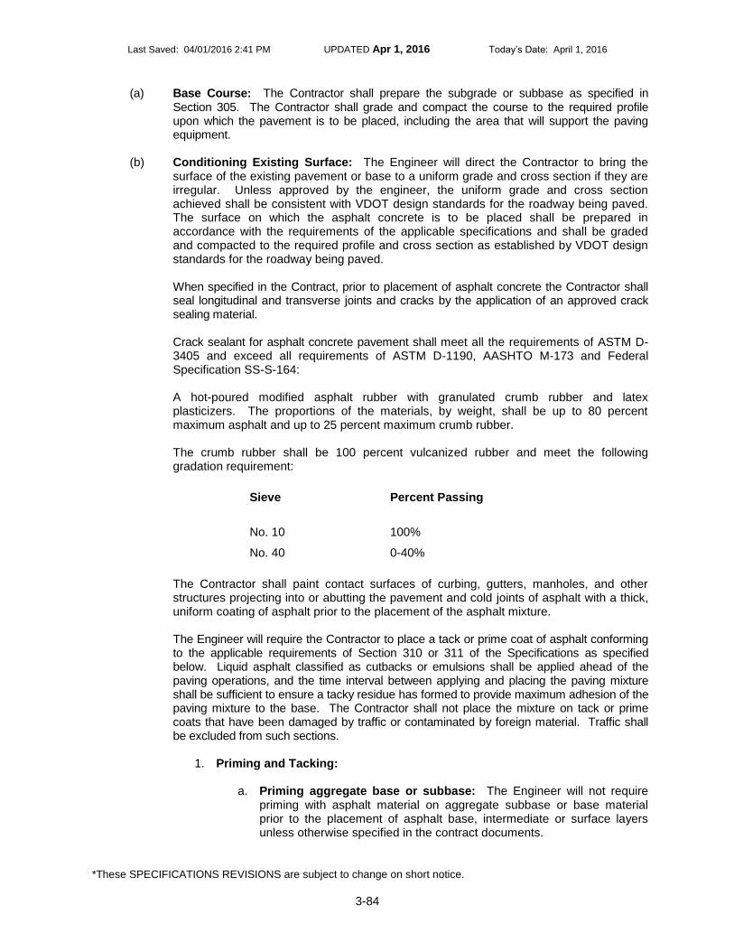
Last Saved: 04/01/2016 2:41 PM UPDATED Apr 1, 2016 Today’s Date: April 1, 2016
*These SPECIFICATIONS REVISIONS are subject to change on short notice.
3-84
(a) Base Course: The Contractor shall prepare the subgrade or subbase as specified in Section 305. The Contractor shall grade and compact the course to the required profile upon which the pavement is to be placed, including the area that will support the paving equipment.
(b) Conditioning Existing Surface: The Engineer will direct the Contractor to bring the
surface of the existing pavement or base to a uniform grade and cross section if they are irregular. Unless approved by the engineer, the uniform grade and cross section achieved shall be consistent with VDOT design standards for the roadway being paved. The surface on which the asphalt concrete is to be placed shall be prepared in accordance with the requirements of the applicable specifications and shall be graded and compacted to the required profile and cross section as established by VDOT design standards for the roadway being paved. When specified in the Contract, prior to placement of asphalt concrete the Contractor shall seal longitudinal and transverse joints and cracks by the application of an approved crack sealing material. Crack sealant for asphalt concrete pavement shall meet all the requirements of ASTM D-3405 and exceed all requirements of ASTM D-1190, AASHTO M-173 and Federal Specification SS-S-164: A hot-poured modified asphalt rubber with granulated crumb rubber and latex plasticizers. The proportions of the materials, by weight, shall be up to 80 percent maximum asphalt and up to 25 percent maximum crumb rubber. The crumb rubber shall be 100 percent vulcanized rubber and meet the following gradation requirement:
Sieve
Percent Passing
No. 10 100%
No. 40 0-40%
The Contractor shall paint contact surfaces of curbing, gutters, manholes, and other structures projecting into or abutting the pavement and cold joints of asphalt with a thick, uniform coating of asphalt prior to the placement of the asphalt mixture. The Engineer will require the Contractor to place a tack or prime coat of asphalt conforming to the applicable requirements of Section 310 or 311 of the Specifications as specified below. Liquid asphalt classified as cutbacks or emulsions shall be applied ahead of the paving operations, and the time interval between applying and placing the paving mixture shall be sufficient to ensure a tacky residue has formed to provide maximum adhesion of the paving mixture to the base. The Contractor shall not place the mixture on tack or prime coats that have been damaged by traffic or contaminated by foreign material. Traffic shall be excluded from such sections.
1. Priming and Tacking:
a. Priming aggregate base or subbase: The Engineer will not require priming with asphalt material on aggregate subbase or base material prior to the placement of asphalt base, intermediate or surface layers unless otherwise specified in the contract documents.

Last Saved: 04/01/2016 2:41 PM UPDATED Apr 1, 2016 Today’s Date: April 1, 2016
*These SPECIFICATIONS REVISIONS are subject to change on short notice.
3-85
b. Tacking: Application of tack at joints, adjacent to curbs, gutters, or other appurtenances shall be applied with a hand wand or with spray bar at the rate of 0.2 gallon per square yard. At joints, the tack applied by the hand wand or a spray bar shall be 2 feet in width with 4 to 6 inches protruding beyond the joint for the first pass. Tack for the adjacent pass shall completely cover the vertical face of the pavement mat edge so that slight puddling of asphalt occurs at the joint, and extend a minimum of 1 foot into the lane to be paved. Milled faces that are to remain in place shall be tacked in the same way for the adjacent pass. Use of tack at the vertical faces of longitudinal joints will not be required when paving is performed in echelon. On rich sections or those that have been repaired by the extensive use of asphalt patching mixtures, the tack coat shall be eliminated when directed by the Engineer. Tack shall not be required atop asphalt stabilized open-graded material drainage layers. Tack shall be applied between the existing asphalt surface and each asphalt course placed thereafter.
2. Removing depressions and elevating curves: Where irregularities in the existing surface will result in a course more than 3 inches in thickness after compaction, the Contractor shall bring the surface to a uniform profile by patching with asphalt concrete and thoroughly tamping or rolling the patched area until it conforms with the surrounding surface. The mixture used shall be the same as that specified for the course to be placed. When the Contractor elects to conduct operations to eliminate depressions, elevate curves, and place the surface course simultaneously, he shall furnish such additional spreading and compacting equipment as required to maintain the proper interval between the operations.

Last Saved: 04/01/2016 2:41 PM UPDATED Apr 1, 2016 Today’s Date: April 1, 2016
*These SPECIFICATIONS REVISIONS are subject to change on short notice.
3-86
TABLE III-2
Cold Weather Paving Limitations
(c) Placing and Finishing: The Contractor shall not place asphalt concrete until the Engineer
approves the surface upon which it is to be placed. The Contractor’s equipment and placement operations shall properly control the pavement width and horizontal alignment. The Contractor shall use an asphalt paver to distribute asphalt concrete over the widest pavement width practicable. Wherever practicable and when the capacity of sustained production and delivery is such that more than one paver can be successfully and continuously operated, pavers shall be used in echelon to place the wearing course in adjacent lanes. Crossovers, as well as areas containing manholes or other obstacles that prohibit the practical use of mechanical spreading and finishing equipment may be constructed using hand tools. However, the Contractor shall exercise

Last Saved: 04/01/2016 2:41 PM UPDATED Apr 1, 2016 Today’s Date: April 1, 2016
*These SPECIFICATIONS REVISIONS are subject to change on short notice.
3-87
care to obtain the required thickness, jointing, compaction, and surface smoothness in such areas. The longitudinal joint in one layer shall offset that in the layer immediately below by approximately 6 inches or more. The joint in the wearing surface shall be offset 6 inches to 12 inches from the centerline of the pavement if the roadway comprises two traffic lanes. The joint should be offset approximately 6 inches from the lane lines if the roadway is more than two lanes in width. The Engineer will not require offsetting layers when adjoining lanes are paved in echelon and the rolling of both lanes occurs within 15 minutes after laydown. The Contractor shall have a certified Asphalt Field Level II Technician present during all paving operations. Immediately after placement and screeding, the surface and edges of each layer shall be inspected by the Asphalt Field Level II Technician to ensure compliance with the asphalt placement requirements and be straightedge to verify uniformity and smoothness. The Asphalt Field Level II Technician shall make any corrections to the placement operations, if necessary, prior to compaction. The finished pavement shall be uniform and smooth. The Contractor’s Asphalt Field Level II Technician shall be present during all density testing. The placement of asphalt concrete shall be as continuous as possible and shall be scheduled such that the interruption occurring at the completion of each day’s work will not detrimentally affect the partially completed work. Material that cannot be spread and finished in daylight shall not be dispatched from the plant unless the Engineer approves the use of artificial lighting. When paving is performed at night, the Contractor shall provide sufficient light to properly perform and thoroughly inspect every phase of the operation. Such phases include cleaning planed surfaces, applying tack, paving, compacting, and testing. Lighting shall be provided and positioned so as to not create a blinding hazard to the traveling public. During compaction of asphalt concrete, the Contractor shall ensure the roller shall not pass over the end of freshly placed material except when a transverse construction joint is to be formed. Edges of pavement shall be finished true and uniform. Asphalt concrete SUPERPAVE pavement courses shall be placed in layers not exceeding four times the nominal maximum size aggregate in the asphalt mixture. The maximum thickness may be reduced if the mixture cannot be adequately placed in a single lift and compacted to the required uniform density and smoothness. The minimum thickness for a pavement course shall be no less than 2.5 times the nominal maximum size aggregate in the asphalt mixture. Nominal maximum size aggregate for each mix shall be defined as one sieve size larger than the first sieve to retain more than 10 percent aggregate as shown in the design range specified in Section 211.03, Table II-13. The Contractor may place base courses in irregularly shaped areas of pavement such as transitions, turn lanes, crossovers, and entrances in a single lift. The Contractor shall square up overlays in excess of 220 pounds per square yard or lanes with a milled depth greater than 2 inches prior to opening to traffic. The Contractor shall cut drainage outlets through the shoulder at locations the Engineer designates, excluding curb and gutter sections, on the milled roadway areas that are to be opened to traffic. Plan and prosecute the milling operation to avoid the trapping of water on the roadway and restore drainage outlets to original grade once paving operations are completed, unless otherwise directed by the Engineer. The cost for

Last Saved: 04/01/2016 2:41 PM UPDATED Apr 1, 2016 Today’s Date: April 1, 2016
*These SPECIFICATIONS REVISIONS are subject to change on short notice.
3-88
cutting and restoring the drainage slots in the roadway shoulder shall be included in the price bid for other items of work. The Contractor shall plan and prosecute a schedule of operations so that milled roadways shall be overlaid with asphalt concrete as soon as possible. In no instance, shall the time lapse exceed 14 days after the milling operations, unless otherwise specified in Section 515 or other provisions in the contract. The Contractor shall keep milled areas of the roadway free of irregularities and obstructions that may create a hazard or annoyance to traffic in accordance with the requirements of Section 104. The Contractor shall use a short ski or shoe to match the grade of the newly overlaid adjacent travel lane on primary, interstate, and designated secondary routes. Unless otherwise directed by the Engineer, a 24-foot minimum automatic grade control ski shall be used on asphalt mixtures on divided highways, with the exception of overlays that are less than full width and the first course of asphalt base mixtures over aggregate subbases. Care shall be exercised when working along curb and gutter sections to provide a uniform grade and joint. The Contractor shall construct the final riding surface to tie into the existing surface by an approved method, which shall include the cutting of a notch into the pavement. In addition to notching, the Contractor may use an asphalt mix design containing a fine-graded mix to achieve a smooth transition from the new asphalt concrete overlay to the existing pavement, with the approval of the Engineer. The material shall be of a type to ensure that raveling will not occur. The cost for constructing tie-ins in the asphalt concrete overlay shall be included in the price bid for asphalt concrete. The Contractor shall clean the existing pavement surface of all accumulated dust, mud, or other debris that may in the opinion of the Engineer detrimentally affect or prevent the bond of the new overlay prior to application of tack coat and commencement of paving operations. The Contractor shall ensure the surface remains clean until commencement of and during paving operations. The cost for cleaning and surface preparation shall be included in the bid price for asphalt concrete. The Contractor shall employ a Material Transfer Vehicle (MTV) during the placement of surface mixes (SM) on all Interstate routes. The Contractor’s paving operation shall have remixing capability in either the MTV or a paver-mounted hopper to produce a uniform, nonsegregated mix with uniform temperature. The MTV and paver combination shall have a minimum storage capacity of 15 tons. In the event of an equipment break down of the paving train, paving shall be discontinued once the material on-site has been placed and no more material shall be shipped from the asphalt plant. When required in the Contract, a MTV shall be used during the placement of designated asphalt mixes on full lane width applications.
(d) Compacting: Immediately after the asphalt mixture is placed and struck off and surface irregularities are corrected, the mixture shall be thoroughly and uniformly compacted by rolling. Rolling shall be a continuous process, insofar as practicable, and all parts of the pavement shall receive uniform compaction. The asphalt surface shall be rolled when the mixture is in the proper condition. Rolling shall not cause undue displacement, cracking, or shoving of the placed mixture. The Contractor shall use the number, weight, and type of rollers sufficient to obtain the required compaction while the mixture is in a workable condition. The sequence of rolling operations and the selection of roller types shall provide the specified pavement density.

Last Saved: 04/01/2016 2:41 PM UPDATED Apr 1, 2016 Today’s Date: April 1, 2016
*These SPECIFICATIONS REVISIONS are subject to change on short notice.
3-89
Rolling shall begin at the sides and proceed longitudinally parallel with the center of the pavement, each trip overlapping at least 6 inches, gradually progressing to the crown of the pavement. When abutting a previously placed lane, rolling shall begin at the outside unconfined side and proceed toward the previously placed lane. On superelevated curves, rolling shall begin at the low side and proceed to the high side by overlapping of longitudinal trips parallel with the centerline. The Contractor shall correct displacements occurring as a result of reversing the direction of a roller or other causes at once by the use of rakes or lutes and the addition of fresh mixture when required. Care shall be taken in rolling not to displace or distort the line and grade of the edges of the asphalt mixture. The Contractor shall keep the wheels/drums of the rollers properly moistened with water, water mixed with a very small quantity of detergent or other Engineer approved material to prevent adhesion of the mixture to the rollers. The Engineer will not allow the use or presence of excess liquid on the rollers. The Contractor shall thoroughly compact the mixture by the use of hot hand tampers, smoothing irons, or mechanical tampers along forms, curbs, headers, walls, and other places not accessible to rollers. On depressed areas, a trench roller or cleated compression strips may be used under the roller to ensure proper compression. Edges of finished asphalt pavement surfaces shall be true curves or tangents. The Contractor shall correct irregularities. The Contractor shall protect the surface of the compacted course until the material has cooled sufficiently to support normal traffic without marring.
(e) Density: Density shall be determined in accordance with the following:
1. The Contractor shall perform roller pattern and control strip density testing on surface, intermediate, and base courses in accordance with the requirements of VTM-76. The Contractor shall have a certified Asphalt Field Technician II perform all density testing. Density shall be determined with a thin-lift nuclear gauge conforming to the requirements of VTM-81 or from the testing of plugs/cores taken from the roadway where the mixture was placed. Density test locations shall be marked and labeled in accordance with the requirements of VTM-76. When acceptance testing is performed with a nuclear gauge, the Contractor shall have had the gauge calibrated within the previous 12 months by an approved calibration service. In addition, the Contractor shall maintain documentation of such calibration service for the 12-month period from the date of the calibration service. The required density of the compacted course when tested with a nuclear gauge shall not be less than 98.0 percent and not more than 102.0 percent of the target control strip density. Nuclear density roller pattern and control strip density testing shall be performed on asphalt concrete overlays placed directly on surface treatment roadways and when overlays are placed at an application rate less than 125 pounds per square yard, based on 110 pounds per square yard per inch, on any surface. In these situations, the Engineer will not require sawed plugs or core samples and the minimum control strip densities as specified in Table III-3 will not be required.

Last Saved: 04/01/2016 2:41 PM UPDATED Apr 1, 2016 Today’s Date: April 1, 2016
*These SPECIFICATIONS REVISIONS are subject to change on short notice.
3-90
The required density of the compacted course shall not be less than 98.0 percent and more than 102.0 percent of the target control strip.

Last Saved: 04/01/2016 2:41 PM UPDATED Apr 1, 2016 Today’s Date: April 1, 2016
*These SPECIFICATIONS REVISIONS are subject to change on short notice.
3-91
TABLE III-3
Minimum Control Strip Density Requirements
Mixture Type
Min. Control Strip Density (%)1
SM-9.5A, 12.5A 92.5
SM-9.5D, 12.5D 92.5
SM-9.5E, 12.5E 92.5
IM-19.0A, IM-19.0D, IM-19.0E 92.2
BM-25.0A, BM-25.0D 92.2
1The control strip density requirement is the percentage of theoretical maximum density
of the job-mix formula by SUPERPAVE mix design or as established by the Engineer based on two or more production maximum theoretical density tests.
The Engineer will divide the project into "control strips" and "test sections" for the purpose of defining areas represented by each series of tests.
a. Control Strip: Control strips shall be constructed in accordance with these specifications and VTM-76. The term control strip density is defined as the average of 10 determinations selected at stratified random locations within the control strip. The Contractor shall construct one control strip at the beginning of work on each roadway and shoulder course and on each lift of each course. The Engineer will require the Contractor to construct an additional control strip when a change is made in the type or source of materials; whenever a significant change occurs in the composition of the material being placed from the same source; or when there is a failing test strip. During the evaluation of the initial control strip, the Contractor may continue paving operations, however, paving and production shall be discontinued during construction and evaluation of any additional control strips. In the event two consecutive control strips fail, subsequent paving operations shall cease until the Contractor recommends correctives actions to the Engineer and the Engineer has approved the Contractor to proceed with the corrective action(s). If the Contractor and the Engineer mutually agree that the required density cannot be obtained because of the condition of the existing pavement structure, the target control strip density shall be determined from the roller pattern that achieves the optimum density and this target control strip density shall be used on the remainder of the roadway that exhibits similar pavement conditions. Either the Engineer or the Contractor may initiate the construction of an additional control strip at any time. The length of the control strip shall be approximately 300 feet and the width shall not be less than 6 feet. On the first day of construction or beginning of a new course, the control strip shall be started between 500 and 1,000 feet from the beginning of the paving operation. The

Last Saved: 04/01/2016 2:41 PM UPDATED Apr 1, 2016 Today’s Date: April 1, 2016
*These SPECIFICATIONS REVISIONS are subject to change on short notice.
3-92
Contractor shall construct the control strip using the same paving, rolling equipment, procedures, and thickness as shall be used on the remainder of the course being placed. The Contractor’s Asphalt Field Level II Technician shall take one reading at each of 10 stratified random locations. No determination shall be made within 12 inches of the edge of any application width for surface and intermediate mixes or within 18 inches of the edge of any application width for base mixes. The average of these 10 determinations shall be the control strip density recorded to the nearest 0.1 pound per cubic foot. The minimum control strip density shall be determined in accordance with the requirements of VTM-76. The control strip shall be considered a lot. If the control strip density conforms to the requirements specified in Table III-3, the Engineer will consider the control strip to be acceptable and the control strip density shall become the target control strip density. If the density does not conform to the requirements specified in Table III-3, the tonnage placed in the control strip and any subsequent paving prior to construction of another control strip will be paid for in accordance with Table III-4 on the basis of the percentage of the Table III-3 value achieved. The Contractor shall take corrective action(s) to comply with the density requirement specified in Table III-3.
TABLE III-4 Payment Schedule for Failing Control Strips
% TMD % of Payment
90.0-92.2/92.51 95
88.0-89.9 90
Less than 88.0 75
1 For SM-9.5 and SM-12.5 mixes, the minimum density value is 92.5%
per Table III-3. For IM-19.0 and BM-25.0 mixes, the minimum density value is 92.2 per Table III-3.
b. Test section (lot): For the purposes of determining acceptance, the Engineer will consider each day’s production as a lot unless the paving length is less than 3,000 linear feet or greater than 7,500 linear feet. When paving is less than 3,000 feet, that day’s production will be combined with the previous day’s production or added to the next day’s production to create a lot as described below. The standard size of a lot will be 5,000 linear feet (five 1,000 foot sublots) of any pass 6 feet or greater made by the paving train for the thickness of the course. If the Engineer approves, the lot size may be increased to 7,500 linear foot lots with five 1,500 foot sublots when the Contractor’s normal daily production exceeds 7,000 feet. Pavers traveling in echelon will be considered as two passes. When a partial lot occurs at the end of a day’s production or upon completion of the project, the lot size will be redefined as follows:
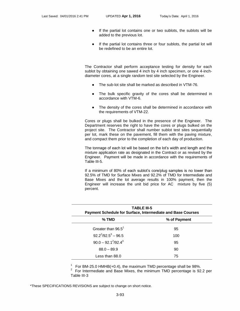
Last Saved: 04/01/2016 2:41 PM UPDATED Apr 1, 2016 Today’s Date: April 1, 2016
*These SPECIFICATIONS REVISIONS are subject to change on short notice.
3-93
● If the partial lot contains one or two sublots, the sublots will be added to the previous lot.
● If the partial lot contains three or four sublots, the partial lot will be redefined to be an entire lot.
The Contractor shall perform acceptance testing for density for each sublot by obtaining one sawed 4 inch by 4 inch specimen, or one 4-inch-diameter cores, at a single random test site selected by the Engineer.
● The sub-lot site shall be marked as described in VTM-76.
● The bulk specific gravity of the cores shall be determined in accordance with VTM-6.
● The density of the cores shall be determined in accordance with the requirements of VTM-22.
Cores or plugs shall be bulked in the presence of the Engineer. The Department reserves the right to have the cores or plugs bulked on the project site. The Contractor shall number sublot test sites sequentially per lot, mark these on the pavement, fill them with the paving mixture, and compact them prior to the completion of each day of production. The tonnage of each lot will be based on the lot’s width and length and the mixture application rate as designated in the Contract or as revised by the Engineer. Payment will be made in accordance with the requirements of Table III-5. If a minimum of 80% of each sublot’s core/plug samples is no lower than 92.5% of TMD for Surface Mixes and 92.2% of TMD for Intermediate and Base Mixes and the lot average results in 100% payment, then the Engineer will increase the unit bid price for AC mixture by five (5) percent.
TABLE III-5 Payment Schedule for Surface, Intermediate and Base Courses
% TMD % of Payment
Greater than 96.51 95
92.22/92.5
3 – 96.5 100
90.0 – 92.12/92.4
3 95
88.0 – 89.9 90
Less than 88.0 75
1 For BM-25.0 HMHB(+0.4), the maximum TMD percentage shall be 98%.
2 For Intermediate and Base Mixes, the minimum TMD percentage is 92.2 per
Table III-3

Last Saved: 04/01/2016 2:41 PM UPDATED Apr 1, 2016 Today’s Date: April 1, 2016
*These SPECIFICATIONS REVISIONS are subject to change on short notice.
3-94
3 For Surface Mixes, the minimum TMD percentage is 92.5% per Table III-3
The Engineer at any time on any project may perform lot density verification testing. Lot density verification is performed by testing plugs. The Contractor shall be responsible for taking plugs for testing. The Engineer will perform verification testing of the plugs per the VDOT Manual of Instructions Section 503.03 – Verification Density Testing. If the Contractor disputes either the density of the plugs determined or the resulting pay factor does not provide for at least 100% payment of the unit bid price, then the Contractor may request the referee procedure to be invoked as outlined in Section 503.03(a)(1). Payment for that lot, will be in accordance with the specifications in Table III-5. Longitudinal joints shall also be tested for density using a nuclear density gauge at each test site in the sublot. For surface and intermediate mixes, the edge of the gauge shall be placed within 4 inches of the joint. For base mixes, the edge of the gauge shall be placed within 6 inches of the joint. The Contractor shall not place the gauge over top of the joint. The joint density value shall be recorded. The Contractor shall report to the Engineer and institute corrective action if a single longitudinal joint density reading is less than 95 percent of the target control strip density. The Engineer will not use the values obtained from the joint readings in payment calculation. The Contractor shall furnish the test data developed during the day’s paving to the Engineer by the end of the day’s operations.
2. Surface, intermediate, and base courses not having a sufficient quantity of material to run a roller pattern and control strip shall be compacted to a minimum density of 91.5 percent of the theoretical maximum density as determined in accordance with the requirements of VTM-22. The Contractor shall be responsible for cutting cores or sawing plugs for testing by the Department. One set of plugs/cores shall be obtained within the first 20 tons of small quantity paving and every 100 tons thereafter for testing by the Department. Core/plug locations shall be randomly selected. If the density is determined to be less than 91.5 percent, the Engineer will make payment in accordance with the requirements of Table III-6.
TABLE III-6 Payment Schedule for Surface, Intermediate and Base Courses
(Not sufficient quantity to perform density roller pattern and control strip)
% TMD % of Payment
Greater than 91.5 100
90.2-91.4 95
88.3-90.1 90
Less than 88.2 75

Last Saved: 04/01/2016 2:41 PM UPDATED Apr 1, 2016 Today’s Date: April 1, 2016
*These SPECIFICATIONS REVISIONS are subject to change on short notice.
3-95
Any section in which a mixture (e.g., SM-9.0) is being placed at an application rate of less than 125 pounds per square yard (based on 110 pounds per square yard per inch) that does not have a sufficient quantity of material for a roller pattern and control strip shall be compacted by rolling a minimum of three passes with a minimum 8-ton roller. The Engineer will not require density testing. For asphalt patching, the minimum density of 91.5 percent of the maximum theoretical density will be determined in accordance with the requirements of VTM-22. The Contractor is responsible for cutting cores or sawing plugs. One set of plugs/cores shall be obtained within the first 20 tons of patching material and every 100 tons thereafter for testing by the Contractor or the Department. The Engineer will randomly select core/plug locations. If the density is less than the 91.5 percent, payment will be made on the tonnage within the 20 or 500 ton lot in accordance with the requirements of Table III-5.
(f) Joints: Transverse joints shall be formed by cutting back on the previous run to expose the full depth of the course. A coat of asphalt shall be applied to contact surfaces of transverse joints just before additional mixture is placed against the previously rolled material. Joints adjacent to curbs, gutters, or adjoining pavement shall be formed by hand placing sufficient mixture to fill any space left uncovered by the paver. The joint shall then be set up with rakes or lutes to a height sufficient to receive full compression under the rollers.
(g) Rumble Strips: This work shall consist of constructing rumble strips on mainline shoulders of highways by cutting 1/2-inch-deep concave depressions into existing asphalt concrete surfaces as shown on the VDOT Standards Drawings and as directed by the Engineer. Rumble strips shall be installed in accordance with the details of the RS-1 (shoulders) or RS-3 (centerline) Standard Drawings. The Contractor shall demonstrate to the Engineer the ability to achieve the desired surface regarding alignment, consistency, and conformity with these specifications and the Standards Drawings prior to beginning production work on mainline shoulders. The test site shall be approximately 25 feet longitudinally at a location mutually agreed upon by the Contractor and Engineer. The Contractor shall coat the entire rumble strip area with liquid asphalt coating (emulsion) using a pressure distributor following the cutting and cleaning of the depressions of waste material. For rumble strips installed on the shoulder, the approximate application rate shall be 0.1 gallons per square yard. For rumble strips installed in a new asphalt concrete surface (new construction or overlay) along the centerline, no sealing of the rumble strip area shall be performed. When the rumble strip is installed along the centerline in an existing asphalt concrete surface (i.e. more than one year since placement), the approximate application rate shall be 0.05 gallons per square yard. The application temperature shall be between 160 degrees F and 180 degrees F. For shoulder rumble strips only, overspray shall not extend more than 2 inches beyond the width of the cut depressions and shall not come in contact with pavement markings. Rumble strips shall not be installed on shoulders of bridge decks, in acceleration/deceleration lanes, on surface drainage structures, or in other areas identified by the Engineer.

Last Saved: 04/01/2016 2:41 PM UPDATED Apr 1, 2016 Today’s Date: April 1, 2016
*These SPECIFICATIONS REVISIONS are subject to change on short notice.
3-96
Waste material resulting from the operation shall be removed from the paved surface and shall not be disposed of where waterways may be at risk of contamination.
(h) Saw-Cut Asphalt Pavement: This work shall consist of saw-cutting the existing asphalt pavement to a depth shown on the plans or as directed by the Engineer.
315.06—Pavement Samples The Contractor shall cut samples from the compacted pavement for testing of depth and density. Samples shall be taken for the full depth of the course at the locations selected by the Engineer. The removed pavement shall be replaced with new mixture and refinished. No additional compensation will be allowed for furnishing test samples and reconstructing areas from which they were taken. 315.07—Pavement Tolerances
(a) Surface Tolerance: The Engineer will test the pavement surface by using a 10-foot
straightedge. The variation of the surface from the testing edge of the straightedge between any two contacts with the surface shall not be more than 1/4 inch. The Contractor shall correct humps and depressions exceeding the specified tolerance or the defective work shall be removed and replaced with new material.
(b) Finished Grade Tolerance: After placement of the final pavement layer, finished grade
elevations shall be within +/–0.04 foot of the elevations indicated in the plans unless otherwise specified, provided that the actual cross slope does not vary more than 0.20 percent from the design cross slope indicated in the plans and the pavement thickness conforms to the thickness tolerances specified herein.
If the Engineer determines either the finished grade elevations or cross slope exceed the tolerances specified, the Contractor shall submit a plan of corrective action to the Engineer for approval.
(c) Thickness Tolerance: The thickness of the base course will be determined by the
measurement of cores as described in VTM-32.
Acceptance of asphalt concrete base course for depth will be based on the mean result of measurements of samples taken from each lot of material placed. A lot of material is defined as the quantity being tested for acceptance except that the maximum lot size will be 1 mile of 24-foot-width base course. A lot will be considered acceptable for depth if the mean result of the tests is within the following tolerance of the plan depth for the number of tests taken:
Plan Depth 1 test 2 tests 3 tests 4 tests
≤ 4" 0.6" 0.5" 0.4" 0.3"
>4." ≤8" 0.9" 0.7" 0.5" 0.4"
>8"≤12" 1" 0.9" 0.7" 0.5"
>12" 1.2" 1" 0.8" 0.6"

Last Saved: 04/01/2016 2:41 PM UPDATED Apr 1, 2016 Today’s Date: April 1, 2016
*These SPECIFICATIONS REVISIONS are subject to change on short notice.
3-97
If an individual depth test exceeds the one test tolerance for the specified plan depth, the Engineer will exclude that portion of the lot represented by the test from the lot. If an individual test result indicates that the depth of material represented by the test is more than the tolerance for one test, the Contractor will not be paid for that material in excess of the tolerance throughout the length and width represented by the test. If an individual test result indicates that the depth of the material represented by the test is deficient by more than the one test tolerance for the plan depth, the Contractor shall correct the base course represented by the test as specified hereinafter. If the mean depth, based on two or more tests, of a lot of material is excessive (more than the plan depth specified in the contract), the Engineer will not pay the Contractor for any material in excess of the tolerance throughout the length and width of the lots represented by the tests. If the mean depth, based on two or more tests, of a lot of material is deficient (less than the plan depth specified in the contract) by more than the allowable tolerance, the Contractor will be paid for the quantity of material that has been placed in the lot. Any required corrective action will be determined by the Engineer. For excessive depth base courses, the rate of deduction from the tonnage allowed for payment as base course will be calculated at a weight of 115 pounds per square yard per inch of depth in excess of the tolerance. For sections of base course that are deficient in depth by more than the one test tolerance and less than two and half times the one test tolerance, the Contractor shall furnish and place material specified for the subsequent course to bring the base course depth within the tolerance. This material will be measured on the basis of tonnage actually placed, determined from weigh tickets, and will be paid for at the contract unit price for the base course material. Such material shall be placed in a separate course. If the deficiency is more than two and half times the one test tolerance, the Contractor shall furnish and place base course material to bring the base course thickness within the tolerance. Corrections for deficient base course depth shall be made in a manner to provide a finished pavement that is smooth and uniform. Sections requiring significant grade adjustments which have been previously identified and documented by the Engineer as being outside of the control of the Contractor will be exempt from deduction or corrective action. When the Contract provides for the construction or reconstruction of the entire pavement structure, the surface and intermediate courses shall be placed at the rate of application shown on the plans within an allowable tolerance of ±5 percent of the specified application rate for application rates of 100 pounds per square yard or greater and within 5 pounds per square yard for application rates of less than 100 pounds per square yard. The Engineer will deduct the amount of material exceeding the allowable tolerance from the quantities eligible for payment. When the Contract provides for the placement of surface or intermediate courses over existing pavement, over pavements constructed between combination curb and gutter, or in the construction or reconstruction of shoulders, such courses shall be placed at the approximate rate of application shown on the plans. However, the specified rate of application shall be altered where necessary to produce the required riding quality.
315.08—Measurement and Payment Asphalt concrete base will be measured in tons and will be paid for at the contract unit price per ton. This price shall include preparing and shaping the subgrade or subbase, constructing and finishing shoulders and ditches, and removing and replacing unstable subgrade or subbase.

Last Saved: 04/01/2016 2:41 PM UPDATED Apr 1, 2016 Today’s Date: April 1, 2016
*These SPECIFICATIONS REVISIONS are subject to change on short notice.
3-98
Asphalt concrete will be measured in tons and will be paid for at the contract unit price per ton. Net weight information shall be furnished with each load of material delivered in accordance with the requirements of Section 211. Batch weights will not be permitted as a method of measurement unless the Contractor’s plant is equipped in accordance with the requirements of Section 211, in which case the cumulative weight of the batches will be used for payment. Asphalt used in the mixtures, when a pay item, will be measured in tons in accordance with the requirements of Section 109.01 except that transporting vehicles shall be tare weighed prior to each load. The weight will be adjusted in accordance with the percentage of asphalt indicated by laboratory extractions. Tack coat shall be included in the price for other appropriate pay items. Asphalt curb backup material will be measured in tons and will be paid for at the contract unit price per ton. This price shall include placing, tamping, and compacting. Liquid asphalt cement, when a pay item, will be measured in tons and will be paid for at the contract unit price per ton. Material Transfer Vehicle (MTV), when required in the Contract, will not be measured for separate payment. The cost for furnishing and operating the MTV shall be included in the price bid for other appropriate items. Warm Mix Asphalt (WMA) additive or process will not be measured for separate payment, the cost of which, shall be included in the price bid for other appropriate items. Rumble strips will be measured in linear feet and will be paid for at the contract unit price per linear foot of shoulder where the rumble strips are actually placed and accepted, excluding the test site. This distance will be measured longitudinally along the edge of pavement with deductions for bridge decks, acceleration/deceleration lanes, surface drainage structures, and other sections where the rumble strips were not installed. This price shall be full compensation for installation, cleaning up debris and disposal of waste material. The test site will not be measured for payment but shall be included in the unit price for rumble strip. Liquid asphalt coating (rumble strips) will be measured in square yards and will be paid for at the contract unit price per square yard as described herein. This price shall include cleaning rumble strips prior to application of the coating and furnishing and applying coating as specified herein. Saw-cut asphalt concrete pavement will be measured in linear feet for the depth specified and will be paid for at the contract unit price per foot, which price shall be full compensation for saw-cutting the asphalt pavement to the depth specified. These prices shall also include heat stabilization additive, furnishing samples, and maintaining traffic. Payment will be made under:
Pay Item
Pay Unit

Last Saved: 04/01/2016 2:41 PM UPDATED Apr 1, 2016 Today’s Date: April 1, 2016
*These SPECIFICATIONS REVISIONS are subject to change on short notice.
3-99
Asphalt concrete base course (Type) Ton
Asphalt concrete (Type) (Class) Ton
Asphalt concrete curb backup material Ton
Liquid asphalt cement Ton
Rumble strip (Asphalt) Linear foot
Liquid asphalt coating (Rumble strips) Square yard
Saw-cut asphalt concrete (depth) Linear foot

Last Saved: 04/01/2016 2:41 PM UPDATED Apr 1, 2016 Today’s Date: April 1, 2016
*These SPECIFICATIONS REVISIONS are subject to change on short notice.
3-100
GUIDELINES — ASPHALT PROJECTS (PLANT MIX ONLY).
S315LM2-0211
VIRGINIA DEPARTMENT OF TRANSPORTATION SPECIAL PROVISION FOR
SURFACE PREPARATION AND RESTORATION PRIOR TO PLANT MIX OVERLAY
February 2, 2011 I. DESCRIPTION
This work shall consist of removing deteriorated pavement, cleaning the area and repairing with the appropriate asphalt mixes in areas designated by the Engineer. This work is applicable only to the routes or areas designated to be overlaid in this contract and where the Engineer has authorized the limits for preparation and restoration. This preparation and restoration will be accomplished prior to the overlay paving operation. After the preparation, the Contractor will be responsible for maintaining the prepared surface until the overlay has been completed. Definitions: For the purpose of the Specifications surface preparation is defined as the following:
TYPE I - A localized disintegration of the pavement, including distorted areas, no more than 5
inches in depth and no more than 20 square feet in surface area. TYPE II - A localized disintegration of pavement, including distorted areas, no more than 5
inches in depth and more than 20 square feet in surface area. TYPE III - A localized disintegration more than 5 inches in depth, limits of surface area as
defined by the Engineer.
II. MATERIALS Surface preparation and restoration material shall be as follows:
For 0-2 inches - use surface mix For 2-5 inches - use intermediate mix For greater than 5 inches - use base mix or intermediate mix
Tack coat shall conform to the requirements of Section 210 of the Specifications.
III. PROCEDURES The Engineer will designate the limits of surface area for preparation and restoration to be achieved prior to beginning the work. Areas designated for surface preparation and restoration shall be thoroughly cleaned, unsuitable material removed and edges shaped to vertical sides prior to applying tack coat. A tack coat shall be applied to all exposed surfaces of the area which will receive asphalt material. The Contractor shall utilize the mix and type of asphalt for surface preparation and restoration in accordance with Section II Materials that he shall use with that route’s overlay. Asphalt material shall be placed in lifts of no more than 3 inches in depth. After leveling each lift, it shall be compacted with

Last Saved: 04/01/2016 2:41 PM UPDATED Apr 1, 2016 Today’s Date: April 1, 2016
*These SPECIFICATIONS REVISIONS are subject to change on short notice.
3-101
an approved mechanical tamper or other approved method. Care shall be taken to ensure the surface of the finished repaired area conforms to the grade of the surrounding pavement.
IV. MEASUREMENT AND PAYMENT When the bid proposal contains a pay item, corresponding to any of the types below, specified in the “Schedule of Items”; that type of surface preparation and restoration will include the work designated in the corresponding type’s description and be paid for in accordance with the price designated by the bidder. If the bid proposal contains no pay item for the type of surface preparation and restoration as described herein, such as may be discovered in the field; that surface preparation and restoration shall meet the definition of Section I and will be measured and paid for in accordance with the following:
Surface Preparation and Restoration Type I will be measured in tons of asphalt material and paid for at the rate of three times the contract unit bid price per ton of the mix type(s) of asphalt authorized by the Engineer. This price shall include removing and disposing of unsuitable material, preparing the area, furnishing and applying tack coat, furnishing and applying asphalt material, and compaction. Surface Preparation and Restoration Type II will be measured in tons of asphalt material and paid for at the rate of four times the contract unit bid price per ton of the mix type(s) of asphalt authorized by the Engineer. This price shall include removing and disposing of unsuitable material, preparing the area, furnishing and applying tack coat, furnishing and applying asphalt material, and compaction. Surface Preparation and Restoration Type III will be measured in tons of asphalt material and paid for at the rate of five times the contract unit bid price per ton of the mix type(s) of asphalt authorized by the Engineer. This price shall include removing and disposing of unsuitable material, preparing the area, furnishing and applying tack coat, furnishing and applying asphalt material, and compaction.

Last Saved: 04/01/2016 2:41 PM UPDATED Apr 1, 2016 Today’s Date: April 1, 2016
*These SPECIFICATIONS REVISIONS are subject to change on short notice.
3-102
GUIDELINES — ASPHALT PROJECTS (PLANT MIX ONLY). WHEN THIS PROVISION APPLIES INCLUDE THE
FOLLOWING IN THE PROPOSAL: S515B03 Cold Planing Asphalt Operations, SS51505 Planing or Milling Pavement, S315LM2 Sur Prep-Restore -Before Overlay, S315SM1 Seal Crack ACP-HCCP-Bef Ovrly, S315QM1 Mainline Overlay Limits at Intersect.
S315NM5-1215
VIRGINIA DEPARTMENT OF TRANSPORTATION SPECIAL PROVISION FOR
PLACEMENT OF ASPHALT CONCRETE OVERLAYS
December 3, 2015 I. DESCRIPTION
This work shall consist of furnishing and placing asphalt concrete overlay pavement courses on existing roadway surfaces in accordance with the requirements herein and in conformity with the lines, grades, and thickness as established in the Contract or directed by the Engineer. This work shall be performed in accordance with the requirements of Section 211 and Section 315 of the Specifications, and where Stone Matrix Asphalt (SMA) is specified in the Contract, Sections 248 and 317 of the Specifications.
II. EQUIPMENT Equipment for placing asphalt concrete overlay material shall be conform to Section 315.03 of the Specifications, and where Stone Matrix Asphalt (SMA) is specified, Section 317 of the Specifications.
III. PROCEDURES Where pavement planing is required it shall be performed in accordance with the requirements of the Special Provision for COLD PLANING (MILLING) ASPHALT CONCRETE OPERATIONS and Section 515 of the Specifications. No placement of an overlay or deck planing will be permitted on a bridge deck without the prior written approval of the District Bridge Engineer. Limitations of operations for placing asphalt concrete overlays shall be in accordance with the requirements of Section 108.02 of the Specifications, the Contract requirements, and as specified herein. Prior to commencement of paving overlay operations the Contractor shall clean the existing pavement surface to the satisfaction of the Engineer of accumulated dust, mud, or other debris that may adversely affect the bond of the new overlay. In the event the thoroughness of the Contractor’s efforts to clean the existing pavement is questionable, the Engineer may require the Contractor to perform a bond strength test in accordance with the referee system for Nontracking Tack Coat in Section 310 of the Specifications. The cost for cleaning and surface preparation shall be included in the bid price for the asphalt concrete. The following will be corrected by the Engineer ahead of the Contractor’s operations or included in the work performed by the Contractor. When such corrective work is performed by the Contractor, the work will be paid for as designated by the specific pay item(s) in the Contract.
● Pavement irregularities greater than 1 inch in depth shall be filled with a material approved by the Engineer.

Last Saved: 04/01/2016 2:41 PM UPDATED Apr 1, 2016 Today’s Date: April 1, 2016
*These SPECIFICATIONS REVISIONS are subject to change on short notice.
3-103
● Pavement cracks or joints shall be cleaned and filled in accordance with the Special Provision for SEALING CRACKS IN ASPHALT CONCRETE SURFACES OR HYDRAULIC CEMENT CONCRETE PAVEMENT.
The Contractor shall remove thermoplastic and tape pavement markings and raised pavement markers prior to performing paving overlay operations. Thermoplastic and tape pavement markings shall be 90 percent removed so as not to interfere with bonding of pavement overlay or the transfer of the existing marking thickness up through the overlay. In lieu of grinding to eradicate thermoplastic, the Contractor will be permitted to mechanically scrape off thermoplastic markings employing adequate controls so as not to damage the affected pavement to a point where such markings are flush with the existing pavement surface. This work shall be performed in accordance with the requirements of Section 512 and Section 704 of the Specifications except as otherwise permitted herein. The Contractor shall protect and reference utility structures prior to paving in order to locate and/or adjust these structures, if necessary, after paving operations are completed. The protection and referencing of utility structures shall be at no cost to the Department. Temporary transverse pavement-wedge tie-ins shall be constructed where pavement overlay operations are temporarily halted as allowed or required herein, in Section 315 of the Specifications, elsewhere in the Contract documents, or by the Engineer. Each temporary tie-in shall be no less than 3 feet in length for every inch of depth of overlaid pavement and shall consist of a mix that is suitable as a surface mix asphalt to provide a smooth transition between the installed overlay and existing pavement or bridge deck. Such temporary tie-ins shall be constructed prior to the overlaid pavement being opened to traffic. Final transverse pavement tie-ins shall be constructed to provide a smooth transition between newly overlaid pavement and existing pavements, bridge decks, and existing pavement underneath bridge overpasses. Such tie-ins shall conform to the requirements of Standard Drawing ACOT-1 or Section 315.05(c) of the Specifications, as applicable, except that all joints at tie-in locations shall be tested using a 10-foot straightedge in accordance with the requirements of Section 315.07(a) of the Specifications. The variation from the testing edge of the straightedge between any two contact points with the pavement surface shall not exceed 1/4 inch. When planing is necessary at tie-ins to existing pavement or bridge decks to obtain the required overlay depth specified in the Contract; the existing pavement shall be planed in accordance with the requirements of the ACOT-1 Standard or the requirements herein. No pavement overlay shall decrease the vertical clearance under a bridge. In situations where the pavement under the overpass cannot be planed in direct proportion to the overlay to be placed, the new pavement is to be tied down to the existing pavement under the overpass a minimum of 75 feet from the outer edges of the bridge overpass in accordance with Standard Drawing ACOT-1. The ACOT-1 Standard for asphalt concrete overlay transitions shall apply when there is at least one (1.00) inch of grade change between the finished asphalt concrete overlay surface and the existing pavement surface and where any of the following conditions exist:
a. Bridge decks or bridge overpasses are located within the project site to receive the
overlay. b. The Contractor has to tie-in the top course of asphalt concrete overlay to an existing
hydraulic cement concrete pavement surface.
c. The Contractor has to tie-in the top course of the asphalt concrete overlay to an existing asphalt concrete pavement surface and planing is included in the Contract as pay item.

Last Saved: 04/01/2016 2:41 PM UPDATED Apr 1, 2016 Today’s Date: April 1, 2016
*These SPECIFICATIONS REVISIONS are subject to change on short notice.
3-104
When tying in the top course of the asphalt concrete overlay to an existing asphalt concrete pavement surface and there is no pay item in the Contract for planing, the asphalt concrete overlay tie-in shall conform to the requirements of Section 315.07 (a) of the Specifications When the Special Provision for RIDEABILITY applies as specified in the Contract, a distance of 105 feet (0.02 of a mile), measured from the line of the tie-in will be exempted from pay
adjustment. The following restrictions, based on the type of roadway, will apply:
Roadways with Posted Speed Limit of 55 Mph or Greater The Contractor shall install asphalt concrete overlays to the depths specified for the specific routes identified in the Contract. Where asphalt concrete is being overlaid by 2 inches or less on roadways carrying traffic, the Contractor shall have the option of squaring up the overlay operation at the end of each workday or squaring up all travel lanes, excluding shoulders, before the weekend. Shoulders must be squared up within 48 hours after the weekend and prior to continuing mainline paving. All lanes including shoulders must be squared up before holidays or any temporary shutdowns. Where overlays of more than 2 inches are being placed, the Contractor must square up the overlay operation at the end of each workday. This requirement shall apply to travel lanes and shoulders. Asphalt concrete pavement overlay operations shall be performed in only one travel lane at a time. Under no circumstance will the Contractor be permitted to overlay a portion of the width of a travel lane, ramp or loop and leave it exposed to traffic. Where uneven pavement joints exist either transversely or longitudinally at the edges of travel lanes due to the overlay operations, the Contractor shall provide advance warning signage and traffic control devices for the scope of the overlay operation the Contractor is performing in accordance with the details provided in the Contract. The cost for the advance warning devices and signage shall be included in the cost of other appropriate items. Temporary pavement markings and markers required as a result of staging such operations will be measured and paid for in accordance with the Special Provision for SECTION 704—PAVEMENT MARKINGS AND MARKERS included in the Contract. In the event an emergency or an unforeseen circumstance such as equipment failure or breakdown occurs during the Contractor’s operations that prevents the Contractor from squaring up the overlaid surface on adjacent lanes prior to a weekend, a holiday or a temporary shutdown, any additional signage, traffic control devices, or markings or markers required to protect the traveling public shall be provided at the Contractor’s expense. Ramps, exits, and turn lanes are to be paved in such a manner that a longitudinal joint with a surface elevation of 1 inch or more between the existing pavement and the overlay (where the overlay is the higher of the two elevations) will not be left for vehicles to cross within the posted speed limits in a “run-on” situation. Ramps, exits, and turn lanes are to be paved to the extent that the joint crossed by traffic is traversed at an angle close to 90 degrees (perpendicular), or the ramp, exit and turn lane shall be squared up with the adjacent mainline lane at the time of installation. Only approved mixes that have been verified in accordance with the requirements of Section 211.03(f) of the Specifications and have met the requirement for roller pattern density shall be placed on limited access roadways.

Last Saved: 04/01/2016 2:41 PM UPDATED Apr 1, 2016 Today’s Date: April 1, 2016
*These SPECIFICATIONS REVISIONS are subject to change on short notice.
3-105
The Contractor shall ensure positive drainage is provided for all overlaid surfaces in accordance with the requirements of Section 315.05(c) of the Specifications.
B. All Other Roadways Where asphalt concrete is being overlaid to a height of 2 inches or less on roadways carrying traffic, the Contractor shall have the option of squaring up the overlay operation at the end of each workday or squaring up all lanes including shoulders at least once every 4 consecutive workdays, excluding weekends. All lanes including shoulders must be squared up before weekends, holidays, or any temporary shutdowns. Where overlays of more than 2 inches are being placed on roadways carrying traffic the Contractor shall square up the overlay operation at the end of each workday. This requirement shall apply to travel lanes and shoulders. Asphalt concrete pavement overlay operations shall be performed in only one travel lane at a time. Under no circumstance will the Contractor be permitted to overlay a portion of the width of a travel lane, ramp or loop and leave it overnight. Where uneven pavement joints exist either transversely or longitudinally at the edges of travel lanes due to the overlay operations, the Contractor shall provide advance warning signage and traffic control devices at his expense in accordance with the details provided in the Contract for the scope of overlay operation he is performing. In the event an emergency or an unforeseen circumstance such as equipment failure or breakdown occurs during the Contractor’s operations that prevents the Contractor from squaring up the overlaid surface on adjacent lanes prior to a weekend, a holiday or a temporary shutdown, any additional signage, traffic control devices required to protect the traveling public shall be the Contractor’s expense Overlay tie-in requirements to intersecting roads or streets shall be in accordance with the Special Provision for LIMITS OF MAINLINE OVERLAY AT INTERSECTIONS TO PAVED ROADS. The Contractor shall ensure positive drainage is provided for all overlaid surfaces in accordance with the requirements of Section 315.05(c) of the Specifications.
(STANDARD DRAWING ACOT-1 is attached)

Last Saved: 04/01/2016 2:41 PM UPDATED Apr 1, 2016 Today’s Date: April 1, 2016
*These SPECIFICATIONS REVISIONS are subject to change on short notice.
3-106
(Attachment) STANDARD DRAWING ACOT-1 December 2012

Last Saved: 04/01/2016 2:41 PM UPDATED Apr 1, 2016 Today’s Date: April 1, 2016
*These SPECIFICATIONS REVISIONS are subject to change on short notice.
3-107
GUIDELINES — ASPHALT PROJECTS (PLANT MIX ONLY). DO NOT USE STANDARD DRAWING WP-2 (PAGE
303.02) UNLESS SPECIFICALLY REQUESTED BY THE DISTRICT. ANY ADDITION OR VARIATION FROM THIS SPECIFICATION MUST BE SUBMITTED TO AND APPROVED BY THE STATE MATERIALS ENGINEER.
S315OM0-0609
VIRGINIA DEPARTMENT OF TRANSPORTATION SPECIAL PROVISION FOR
TRENCH WIDENING ASPHALT MIXTURES BM-25.0(T), IM-19.0D(T) or IM-19.0A(T)
October 17, 2008cc
SECTION 315—ASPHALT CONCRETE PAVEMENT of the Specifications is amended as follows:
Section 315.01—Description is amended to include the following:
Certain routes in the Contract are designated to use asphalt concrete type BM-25.0(T), IM-19.0A(T) or IM-19.0D(T). Those routes are referred to herein as trench widening routes.
Section 315.02—Materials is amended to add the following:
(e) Trench widening route materials shall conform to the requirements of Section 211 of the
Specifications. IM-19.0A shall be used for IM-19.0A(T) and IM-19.0D shall be used for IM-19.0D(T). Where BM-25.0(T) is designated, either BM-25.0A or BM-25.0D shall be used by the Contractor.
Section 315.05(e)2 Surface, Intermediate and Base Courses is amended to include the following:
Trench Widening Routes — The minimum lift density as determined in accordance with the requirements of VTM-22 is based on the type of trench widening as defined below and specified in the Contract. Where trench widening is 2 foot in width compaction may be performed with small single drum walk-behind rollers or other mechanical means acceptable to the Engineer at the Contractor’s discretion.
Type 1 — Paved Shoulder Only:
Trench widening routes where the widening will serve as a paved shoulder and will not be subjected to constant traffic: The painted edge line will not be on the trench widening. The minimum density requirement will not be enforced. Steel double drum rollers weighing no less than 8 tons shall perform compaction of the asphalt concrete. No less than five passes shall be completed.
Type 2 — Widened Travel Lane and Paved Shoulder:
Trench widening routes where the widening will serve as a wider travel lane and paved shoulder that will be subjected to traffic: The widening will not include removal of existing travel lane pavement, i.e., inside the edge line marking. The painted edge line will be on the trench widening. The minimum density of 91.5 percent shall be enforced.
Type 3 — Repaired Travel Lane and Paved Shoulder:
Trench widening routes where the widening will include a portion of the existing travel lane, serve as a paved shoulder and will be subjected to traffic as a part of the travel lane: The widening will include removal of existing pavement (i.e. inside the
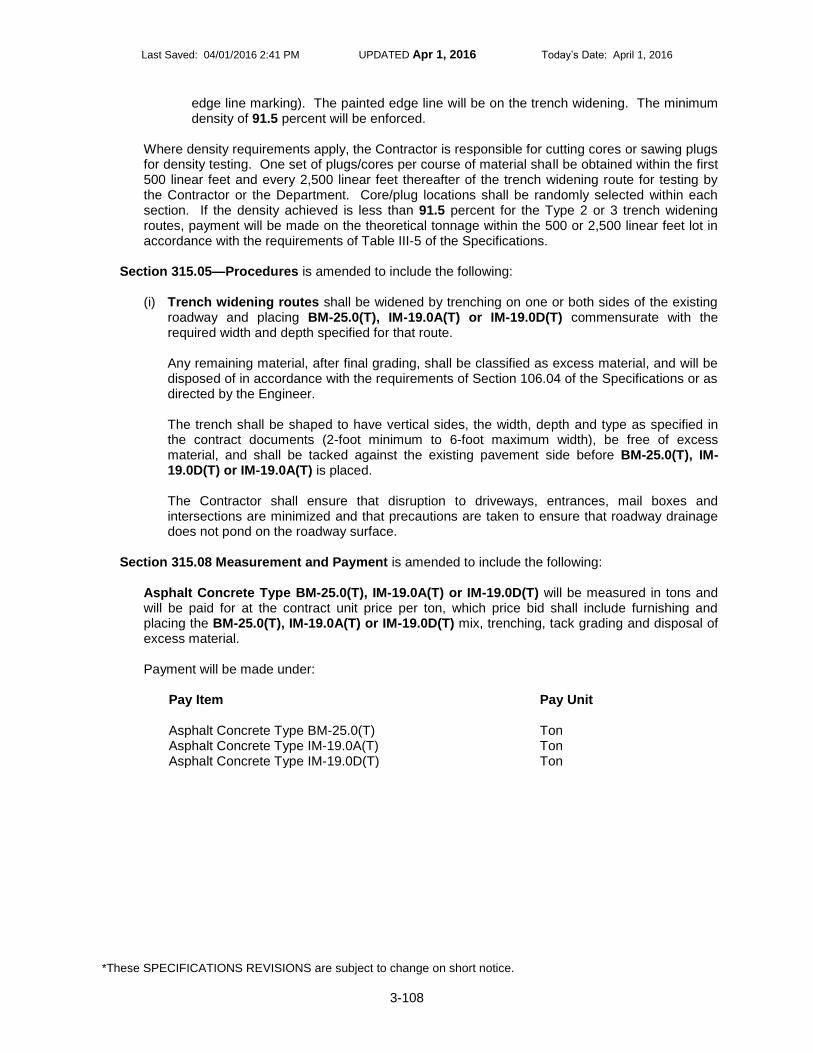
Last Saved: 04/01/2016 2:41 PM UPDATED Apr 1, 2016 Today’s Date: April 1, 2016
*These SPECIFICATIONS REVISIONS are subject to change on short notice.
3-108
edge line marking). The painted edge line will be on the trench widening. The minimum density of 91.5 percent will be enforced.
Where density requirements apply, the Contractor is responsible for cutting cores or sawing plugs for density testing. One set of plugs/cores per course of material shall be obtained within the first 500 linear feet and every 2,500 linear feet thereafter of the trench widening route for testing by the Contractor or the Department. Core/plug locations shall be randomly selected within each section. If the density achieved is less than 91.5 percent for the Type 2 or 3 trench widening routes, payment will be made on the theoretical tonnage within the 500 or 2,500 linear feet lot in accordance with the requirements of Table III-5 of the Specifications.
Section 315.05—Procedures is amended to include the following:
(i) Trench widening routes shall be widened by trenching on one or both sides of the existing
roadway and placing BM-25.0(T), IM-19.0A(T) or IM-19.0D(T) commensurate with the required width and depth specified for that route. Any remaining material, after final grading, shall be classified as excess material, and will be disposed of in accordance with the requirements of Section 106.04 of the Specifications or as directed by the Engineer. The trench shall be shaped to have vertical sides, the width, depth and type as specified in the contract documents (2-foot minimum to 6-foot maximum width), be free of excess material, and shall be tacked against the existing pavement side before BM-25.0(T), IM-19.0D(T) or IM-19.0A(T) is placed. The Contractor shall ensure that disruption to driveways, entrances, mail boxes and intersections are minimized and that precautions are taken to ensure that roadway drainage does not pond on the roadway surface.
Section 315.08 Measurement and Payment is amended to include the following:
Asphalt Concrete Type BM-25.0(T), IM-19.0A(T) or IM-19.0D(T) will be measured in tons and will be paid for at the contract unit price per ton, which price bid shall include furnishing and placing the BM-25.0(T), IM-19.0A(T) or IM-19.0D(T) mix, trenching, tack grading and disposal of excess material. Payment will be made under:
Pay Item
Pay Unit
Asphalt Concrete Type BM-25.0(T) Ton Asphalt Concrete Type IM-19.0A(T) Ton Asphalt Concrete Type IM-19.0D(T) Ton
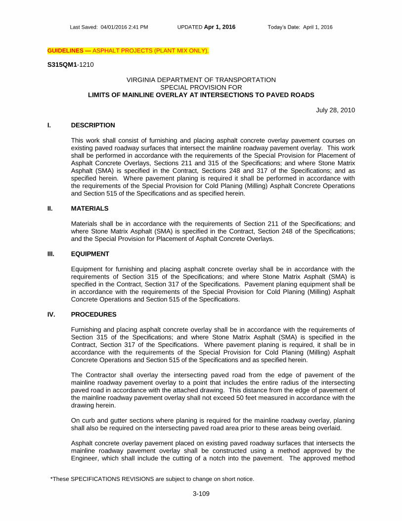
Last Saved: 04/01/2016 2:41 PM UPDATED Apr 1, 2016 Today’s Date: April 1, 2016
*These SPECIFICATIONS REVISIONS are subject to change on short notice.
3-109
GUIDELINES — ASPHALT PROJECTS (PLANT MIX ONLY).
S315QM1-1210
VIRGINIA DEPARTMENT OF TRANSPORTATION SPECIAL PROVISION FOR
LIMITS OF MAINLINE OVERLAY AT INTERSECTIONS TO PAVED ROADS
July 28, 2010 I. DESCRIPTION
This work shall consist of furnishing and placing asphalt concrete overlay pavement courses on existing paved roadway surfaces that intersect the mainline roadway pavement overlay. This work shall be performed in accordance with the requirements of the Special Provision for Placement of Asphalt Concrete Overlays, Sections 211 and 315 of the Specifications; and where Stone Matrix Asphalt (SMA) is specified in the Contract, Sections 248 and 317 of the Specifications; and as specified herein. Where pavement planing is required it shall be performed in accordance with the requirements of the Special Provision for Cold Planing (Milling) Asphalt Concrete Operations and Section 515 of the Specifications and as specified herein.
II. MATERIALS Materials shall be in accordance with the requirements of Section 211 of the Specifications; and where Stone Matrix Asphalt (SMA) is specified in the Contract, Section 248 of the Specifications; and the Special Provision for Placement of Asphalt Concrete Overlays.
III. EQUIPMENT Equipment for furnishing and placing asphalt concrete overlay shall be in accordance with the requirements of Section 315 of the Specifications; and where Stone Matrix Asphalt (SMA) is specified in the Contract, Section 317 of the Specifications. Pavement planing equipment shall be in accordance with the requirements of the Special Provision for Cold Planing (Milling) Asphalt Concrete Operations and Section 515 of the Specifications.
IV. PROCEDURES Furnishing and placing asphalt concrete overlay shall be in accordance with the requirements of Section 315 of the Specifications; and where Stone Matrix Asphalt (SMA) is specified in the Contract, Section 317 of the Specifications. Where pavement planing is required, it shall be in accordance with the requirements of the Special Provision for Cold Planing (Milling) Asphalt Concrete Operations and Section 515 of the Specifications and as specified herein. The Contractor shall overlay the intersecting paved road from the edge of pavement of the mainline roadway pavement overlay to a point that includes the entire radius of the intersecting paved road in accordance with the attached drawing. This distance from the edge of pavement of the mainline roadway pavement overlay shall not exceed 50 feet measured in accordance with the drawing herein. On curb and gutter sections where planing is required for the mainline roadway overlay, planing shall also be required on the intersecting paved road area prior to these areas being overlaid. Asphalt concrete overlay pavement placed on existing paved roadway surfaces that intersects the mainline roadway pavement overlay shall be constructed using a method approved by the Engineer, which shall include the cutting of a notch into the pavement. The approved method

Last Saved: 04/01/2016 2:41 PM UPDATED Apr 1, 2016 Today’s Date: April 1, 2016
*These SPECIFICATIONS REVISIONS are subject to change on short notice.
3-110
shall provide a smooth transition between new pavement and existing pavement. Such tie-ins shall conform to the requirements of Section 315.05(c) of the Specifications except that all joints at tie-in locations shall be tested using a 10-foot straightedge in accordance with the requirements of Section 315.07(a) of the Specifications. The variation from the testing edge of the straightedge between any two contact points with the pavement surface shall not exceed 1/4 inch.
V. MEASUREMENT AND PAYMENT Overlay at intersections to paved roads will be measured and paid for in accordance with the pay items of Section 315 of the Specifications; and where Stone Matrix Asphalt (SMA) is specified in the Contract, Section 317 of the Specifications, and the Special Provision for Cold Planing (Milling) Asphalt Concrete Operations and Section 515 of the Specifications.

Last Saved: 04/01/2016 2:41 PM UPDATED Apr 1, 2016 Today’s Date: April 1, 2016
*These SPECIFICATIONS REVISIONS are subject to change on short notice.
3-111
GUIDELINES — FOR PROJECTS WHERE RIDEABILTY EVALUATION OF ASPHALT CONCRETE PAVEMENT IS
REQUIRED IN WRITING BY THE MATERIALS ENGINEER. THE PROPOSAL MUST CONTAIN THE EXACT LOCATIONS AND LIMITS OF THE RIDEABILTY EVALUATION, INCLUDING INCENTIVE ONLY LOCATIONS. FOR PLANT MIX SCHEDULE PROJECTS THE EXACT LOCATIONS AND LIMITS MUST BE CONTAINED IN SCHEDULE NOTES OR IN A PROJECT SPECIFIC SPCN IN THE PROPOSAL. FOR ALL OTHER TYPES OF PROJECTS THE EXACT LOCATIONS AND LIMITS MUST BE INCLUDED IN A PROJECT SPECIFIC SPCN IN THE PROPOSAL.
S315R01-0115
VIRGINIA DEPARTMENT OF TRANSPORTATION SPECIAL PROVISION FOR
RIDEABILITY
January 22, 2015 SECTION 315—ASPHALT CONCRETE PAVEMENT of the Specifications is amended as follows:
Section 315.07 Pavement Tolerances is amended to include the following: For pavements designated in the Contract, the final ride quality acceptance will be based on the lowest average International Roughness Index (IRI) for each 0.01-mile section produced by a minimum of two test runs, using a South Dakota style road profiling device and reported for each travel lane. The device shall measure both wheelpaths with laser height sensing instruments. The Department will conduct the testing within 30 calendar days from Contractor’s written request for testing following the completion of the final surface course and final pavement striping over the designated section. If temporary pavement marking is placed and the lanes are clearly delineated over the completed final surface course, the Contractor may request ride testing in writing and the Department will conduct testing within 30 calendar days from the request. The Department will conduct the testing as soon as possible upon receipt of the Contractor’s testing request, providing the Contractor can arrange unimpeded access to the paved surface for constant highway speed test runs. Testing will be conducted in accordance to VTM – 106.
I. Acceptance An IRI number in inches per mile will be established for each 0.01-mile section for each designated lane. The last 0.01-mile (52 feet) section before a bridge, the first 0.01-mile (52 feet) section after a bridge, and the beginning and end 0.01-mile (52 feet) sections of the final surface will not be subject to a pay adjustment. Areas excluded from testing by the road profiling device will be tested using a 10-foot straightedge. The variation of the surface from the testing edge of the straightedge between any two contacts with the surface shall not be more than 1/4 inch. Humps and depressions exceeding the specified tolerance shall be subject to correction as directed by the Engineer, at no additional cost to the Department. A. Incentive-disincentive projects
1. General
The following tables provide the acceptance quality of pavement based on the finished rideability for interstate and non-interstate roadways.

Last Saved: 04/01/2016 2:41 PM UPDATED Apr 1, 2016 Today’s Date: April 1, 2016
*These SPECIFICATIONS REVISIONS are subject to change on short notice.
3-112
TABLE A - INTERSTATE SYSTEM
IRI After Completion (Inches Per Mile)
Pay Adjustment (Percent Pavement Unit Price)
45.0 and Under 115
45.1-55.0 110
55.1-70.0 100
70.1-80.0 90
80.1-90.0 80
90.1-100.0 70
100.1-120.0 60 or Subject To Corrective Action
120.1-140.0 40 or Subject to Corrective Action
140.1-160.0 20 or Subject to Correction Action
Over 160.1 0 or Subject to Corrective Action
TABLE B - NON- INTERSTATE SYSTEM
IRI After Completion (Inches Per Mile)
Pay Adjustment (Percent Pavement Unit Price)
55.0 and Under 115
55.1-65.0 110
65.1-80.0 100
80.1-90.0 90
90.1-100.0 80
100.1-110.0 70
110.1-130.0 60 or Subject To Corrective Action
130.1-150.0 40 or Subject to Corrective Action
150.1-170.0 20 or Subject to Corrective Action
Over 170.1 0 or Subject to Corrective Action
The Engineer reserves the right to require corrective action in accordance with Table A and B. The method of correction shall be reviewed and approved by the Engineer and correction shall be performed at the Contractor’s expense. The Engineer may require correction of any or all adjoining traffic lanes or shoulders at the Contractor’s expense to assure uniform cross section. Methods of correction may include, but are not limited to diamond grinding, remove and replace, and asphalt concrete (AC) overlay. Where corrections are made after the initial Department rideability test, the pavement will be retested by the Department to verify that corrections have produced the acceptable ride surface. No incentives will be provided for sections on which corrective actions have been required by the Engineer. Additional corrections may be required by the Engineer based on the retested IRI measurements at the Contractor’s expense. In the event the corrective action(s) do not result in 100 percent payment, and not subject to further corrective action, the Contractor will be assessed the corresponding percent payment.
2. Single-Lift Construction
An AC layer is defined as a material lift equal to or greater than 2.5 times the maximum nominal aggregate size for the AC mix(es) specified in the Contract. A material lift less

Last Saved: 04/01/2016 2:41 PM UPDATED Apr 1, 2016 Today’s Date: April 1, 2016
*These SPECIFICATIONS REVISIONS are subject to change on short notice.
3-113
than the specified application rate or less than 2.5 times the maximum nominal aggregate size for the AC mix(es) specified in the Contract is considered a “scratch course” and not an AC layer. Where only one AC layer shall be placed, the Department will test pavement sites subject to this special provision prior to work by the Contractor. Upon request by the Contractor, the Department will provide the IRI testing results. If this IRI testing is conducted more than 180 calendar days prior to the scheduled beginning of the work, the Department or Contractor may request new IRI testing. Based on the average IRI (original surface and completed overlay) for each 0.1-mile length of each travel lane subject to this special provision, no corrective action will be required if the completed surface has IRI test results which indicate a 30 percent or more improvement in the ride quality. This percent improvement is based on the 0.1-mile paved section average IRI and not the individual 0.01-mile increments. When the percent improvement is achieved for a 0.1-mile section, the payments (incentives, disincentives and full payment) for the individual 0.01-mile increments will be summed. The Contractor will then be paid the greater of the total adjusted payments or 100 percent for that 0.1-mile section.
This rideability specification does not relieve the Contractor from responsibility concerning workmanship in accordance with the requirements of the Specifications, other contract requirements or as defined by the Engineer.
B. Incentive Only Projects
For projects designated as “incentive only”, Table C will be applied for calculating pay adjustment. A pay adjustment calculation will be made at each 0.01 mile segment and summed over each 0.1 mile. Any penalties, calculated at each 0.1 mile, will be ignored for incentive only projects. Only pay adjustment calculation producing an incentive for each 0.1 mile (if any) section will be summed to determine the total incentive over the project. Therefore, no disincentive will be assessed over the entire project. The contractor will be paid the greater of the total incentive or 100 percent payment for the project. The standard exemptions will be applied to calculate the average IRI over the lane.
TABLE C – INCENTIVE ONLY PROJECT
IRI After Completion (Inches Per Mile)
Pay Adjustment (Percent Pavement Unit Price)
60.0 and Under 115
60.1-70.0 110
70.1-85.0 100
85.1-95.0 90
95.1-105.0 80
105.1-115.0 70
115.1-135.0 60
135.1-155.0 40
155.1-175.0 20
Over 175.1 0
Incentive only projects will not be subject to corrective action as a result of the rideability results. Ride testing prior to paving by the Department is not required for incentive only projects. Pay adjustments will be applied to the theoretical tonnage of the surface mix

Last Saved: 04/01/2016 2:41 PM UPDATED Apr 1, 2016 Today’s Date: April 1, 2016
*These SPECIFICATIONS REVISIONS are subject to change on short notice.
3-114
asphalt material for the lane width and section length tested. This rideability specification does not relieve the Contractor from responsibility concerning workmanship in accordance with the requirements of the Specifications, other contract requirements or as defined by the Engineer.
II. Payment Pay adjustments will be applied to the theoretical tonnage of the surface mix asphalt material for the lane width and section length tested (generally 12 feet wide and 52.8 feet long) based on testing prior to any corrective action directed by the Engineer. For the section(s) where corrective action is required, pay adjustment will be based on the testing after the corrective action has been accomplished.

Last Saved: 04/01/2016 2:41 PM UPDATED Apr 1, 2016 Today’s Date: April 1, 2016
*These SPECIFICATIONS REVISIONS are subject to change on short notice.
3-115
GUIDELINES – FOR PROJECTS REQUIRING CRACK SEALING.
S315SM1-1114
VIRGINIA DEPARTMENT OF TRANSPORTATION SPECIAL PROVISION FOR
SEALING CRACKS IN ASPHALT CONCRETE SURFACES OR HYDRAULIC CEMENT CONCRETE PAVEMENT
October 19, 2014
I. DESCRIPTION
This Specification covers the cleaning and sealing of cracks with Type A material for pavements which will not be overlaid with asphalt concrete (AC) within one year. Type B material shall be used to fill cracks in AC surfaces or hydraulic cement pavement (HCC) joints or cracks that will be overlaid within one year. Type C material shall be used to fill cracks in AC surfaces that may or may not be overlaid within one year. The Contract will designate which sites are to use each material. In addition, this Specification covers the routing (Type C only), cleaning and sealing of cracks in existing surfaces including, but not limited to, cracks along the longitudinal joint(s) between lanes. Cracks ranging in width from 1/8 inch to 1 ½ inches shall be sealed. Cracks that exceed 1 ½ inches are not included in this contract.
II. MATERIALS
All sealant materials shall be certified or tested and approved by the Department before being incorporated into the work. Where installation procedures or any part thereof are required to be in accordance with recommendations of the manufacturer of sealant compounds, the Contractor shall submit catalogue data and copies of recommendations to the Engineer prior to installation of the materials for review and approval. All such recommendations shall be adhered to unless directed otherwise by the Engineer. TYPE A The crack sealant shall be of the following type and shall meet all the requirements of ASTM D-6690 and exceed all requirements of AASHTO M-173 and Federal Specification SS-S-164:
A HOT-POURED MODIFIED ASPHALT RUBBER WITH GRANULATED CRUMB RUBBER AND LATEX PLASTICIZERS. The proportions of the materials, by weight, shall be up to 80 percent maximum asphalt and up to 25 percent maximum crumb rubber. The crumb rubber shall be 100 percent vulcanized rubber and meet the following gradation requirement:
Sieve
Percent Passing
No. 10 100% No. 40 0-40%
TYPE B Type B material shall consist of PG 64H-22 and polyester fibers from the Materials Division Manual of Instructions approved list of Stabilizers for Asphalt Mixtures (fibers only). The

Last Saved: 04/01/2016 2:41 PM UPDATED Apr 1, 2016 Today’s Date: April 1, 2016
*These SPECIFICATIONS REVISIONS are subject to change on short notice.
3-116
Contractor shall provide the PG 64H-22 suppliers data for heating. Fibers shall not exceed 5 percent by weight. Fiber loading will be determined at the project site in order to minimize/eliminate the need for over banding as described. The fiber loading will be approved by the Engineer. TYPE C Type C material shall consist of PG 64H-22 and polyester fibers from the Materials Division Manual of Instructions approved list of Stabilizers for Asphalt Mixtures (fibers only) at 5 percent by weight. The Contractor shall provide the PG 64H-22 suppliers data for heating.
III. EQUIPMENT
Proper sealing equipment must be used for the specific material listed in accordance with the manufacturer's recommendations for the Sealant specified. The equipment for hot applied sealant compounds shall be a melting kettle of double boiler, indirect heating type, using oil as a heat-transfer medium. The kettle shall have an effective mechanically operated agitator, a re-circulation pump and shall be equipped with a positive thermostatic temperature control which shall be checked for calibration before beginning work. The unit shall be capable of maintaining the specified mixing temperature within 10 degrees F. Manufacturer's recommendations for mixing and application temperatures shall be followed with the latter being measured at the nozzle of the applicator wand. Overheating or direct heating of the sealant material shall not be permitted. The hoses, connectors and applicator wand shall all be insulated.
IV. CONSTRUCTION
The sealant shall not be placed when the ambient or pavement temperatures fall below 45 degrees F, or when moisture is present in the crack to be sealed. Prior to sealing, cracks shall be thoroughly cleaned as approved by the Engineer using an oil free hot air blasting heat lance capable of a velocity of 3000 fps at 3000 degrees F. Cracks shall be cleaned such that all dirt, debris, moisture and other foreign materials that will prevent bonding of the sealant are removed to a minimum depth of 1 inch. All foreign material (i.e., dirt, grass, rocks) shall be removed from the pavement to prevent re-contamination of the crack. Cracks shall be completely dry before sealing. Any crack not meeting the approval of the Engineer shall be re-cleaned and dried. The sealant shall be pumped directly into the crack from the heater-melter unit at the temperature specified by the manufacturer immediately following the cleaning of each crack. Cracks shall be sealed in the following manner as approved by the Engineer:
TYPE A - Cracks shall be filled from the bottom up in a continuous manner such that the crack is completely filled level with the pavement surface, and the sealant shall overlay the crack at the pavement surface leaving a maximum “over-banded" appearance of 1-inch wide on each side of the crack. The material shall not continue to flow beyond these limits once a crack is sealed. The height of the sealant above the pavement surface shall not exceed 1/8 inch. For this method of sealing, the applicator wand shall be equipped with a shoe that will produce the extruded over-band as well as completely fill the crack. TYPE B - Cracks shall be filled from the bottom up in a continuous manner such that the crack is completely filled level with the pavement surface. The sealant may overlay the surface on each side of the by no more than ½ inch or leave a no “over-banded" appearance. The material shall not continue to flow beyond these limits once a crack is sealed. The height of the sealant above the pavement surface shall not exceed 1/8 inch. For this method of

Last Saved: 04/01/2016 2:41 PM UPDATED Apr 1, 2016 Today’s Date: April 1, 2016
*These SPECIFICATIONS REVISIONS are subject to change on short notice.
3-117
sealing, the applicator wand shall be equipped with a shoe that will minimize the extruded over-band as well as completely fill the crack. TYPE C – Prior to sealing, the cracks shall be routed to a minimum depth of 1 inch and to a minimal width of ½ inch. Cracks shall be filled from the bottom up in a continuous manner such that the crack is completely filled level with the pavement surface, and the sealant shall overlay the crack at the pavement surface leaving a no “over-banded" appearance. The material shall not continue to flow beyond these limits once a crack is sealed. The height of the sealant above the pavement surface shall not exceed 1/8 inch.
Prior to the start of each day’s operation, the applicator wand and hose shall be heated per the equipment manufacturer’s recommendations and the material in the heater-melter unit re-circulated. The applicator wand shall be returned to the mixing unit and the sealant material re-circulated immediately upon completion of each crack sealing. Any crack in hydraulic cement concrete pavement which cannot be filled due to the sealant draining into a large void, shall be plugged with a suitable material (i.e. backer rod) approved by the Engineer prior to the project, and then filled. After being plugged, recleaning of the crack may be required prior to filling with sealant. During the heating and application of the crack sealing material, the temperature of the material shall be measured and recorded on two hour intervals by the Contractor. For Type A material, the material shall never be heated over 420 degrees F. For Type B and C material, the material shall not be heated above 375 degrees F. Any material heated above these temperatures shall be discarded (i.e. all material in the heater-melter unit) and not paid for by the Department. Additionally, if the material becomes lumpy or has poor flow at elevated temperature, then the material shall be discarded (i.e. all material in the heater-melter unit) and not paid for by the Department. Traffic shall be kept off the pavement surface until the crack sealant has cured to the point it will not track or be distorted by traffic. The Contractor shall replace, at his or her expense, any sealant that pulls out within 96 hours after opening the pavement to traffic.
V. METHOD OF MEASUREMENT METHOD A – CONVERSION APPROACH Sealant for cracks or joints will be measured by the pound. At the beginning of each workday, the Engineer, or his or her appointed representative, shall measure the amount of material in the heater-melter unit and log all additional material added during the day, and measure the amount of material remaining in the heater-melter to determine the total poundage used for that day. No payment will be made for waste material. For the purpose of converting the liquid material in the heater-melter unit from gallons to pounds, the Contractor shall use a calibrated measuring rod to determine the actual quantity of material in gallons, and same shall be converted to pounds taking into consideration the temperature of the material at the time of measurement. A chart or other approved conversion method furnished by the sealant material manufacturer/supplier shall be used to perform the conversion from gallons to pounds. METHOD B – DIRECT MEASUREMENT APPROACH

Last Saved: 04/01/2016 2:41 PM UPDATED Apr 1, 2016 Today’s Date: April 1, 2016
*These SPECIFICATIONS REVISIONS are subject to change on short notice.
3-118
Sealant for cracks or joints will be measured by the pound. At the beginning of each workday, the Contractor shall provide the Engineer the certified weight of the heater-melter unit. During the day’s operation, the Engineer will log all additional material added to the heater-melter unit. At the end of the day’s operation, the Contractor shall provide the Engineer the certified weight of the heater-melter unit including the unused material in the heater-melter unit. The Engineer will determine the pounds of material applied for payment purposes. No payment will be made for waste material.
VI. BASIS OF PAYMENT TYPE A and B Crack Sealant/Filler will be paid for at the contract unit price per pound, which price shall be full compensation for providing the sealant/filler, complete-in-place, including cleaning and sealing the cracks and for all tools, labor, equipment, materials and incidentals related fully completing the installation. TYPE C Crack /Sealant/Filler will be paid for at the contract unit price per pound, which price shall be full compensation for providing the sealant/filler, complete-in-place, including routing, cleaning and sealing the cracks and for all tools, labor, equipment, materials and incidentals related fully completing the installation. Payment will be made under:
Pay Item
Pay Unit
Crack Sealant/Filler (Type A) Pound Crack Sealant/Filler (Type B) Pound Crack Sealant/Filler (Type C) Pound

Last Saved: 04/01/2016 2:41 PM UPDATED Apr 1, 2016 Today’s Date: April 1, 2016
*These SPECIFICATIONS REVISIONS are subject to change on short notice.
3-119
GUIDELINES — PROJECTS REQUIRING Asphalt Concrete Type SM-4.75. WHEN THIS PROVISION APPLIES
INCLUDE THE FOLLOWING IN THE PROPOSAL: SS21113 SuperPave -Asphalt Concrete, SS31510 SuperPave -Asphalt Conc Place.
S315U02-1215 VIRGINIA DEPARTMENT OF TRANSPORTATION
SPECIAL PROVISION FOR DENSE GRADED ASPHALT MIX TYPE SM-4.75
October 16, 2015
I. DESCRIPTION
This work shall consist of the production, placement and acceptance criteria of the thin asphalt concrete material designated as type SM-4.75 in accordance with the Contract requirements, this provision, and as directed by the Engineer. SM-4.75 mix types are specified as one of the types listed as follows:
Mix Type Asphalt Performance Grade
SM-4.75A 64S-22
SM-4.75D 64H-22
SM-4.75E 64E-22
II. MATERIALS A. Asphalt: The asphalt cement shall be performance graded asphalt (PG) 64S-22, 64H-22
or 64E-22 meeting the requirements of Section 210 of the Specifications or as designated by the Engineer.
B. RAP: Recycled asphalt pavement material will be permitted in accordance with Table II-
14A in Section 211 of the Specifications. C. Coarse aggregate shall conform to the requirements of Section 203 of the
Specifications, except for grading, or as directed by the Engineer. D. Fine aggregate shall conform to the requirements of Section 202 of the Specifications,
except for grading. The uncompacted void content shall not have a value less than 40 percent when tested in accordance with AASHTO T 304 Method A and the sand equivalent value shall not be less than 40 percent when tested in accordance with AASHTO T 176.
E. Anti-stripping Additive shall be hydrated lime at a rate of one percent of the total mix or
a chemical anti-stripping agent, which has a proven performance in asphalt concrete using the same aggregate sources as approved by the Engineer.
III. MIX GRADATION LIMITS The Contractor shall submit for the Engineer’s approval, a job mix formula within the following design ranges of percent passing each sieve size as noted:
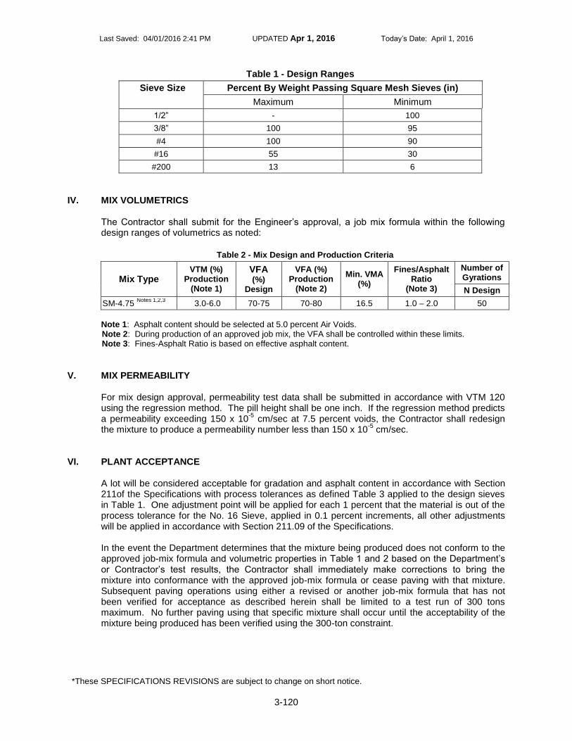
Last Saved: 04/01/2016 2:41 PM UPDATED Apr 1, 2016 Today’s Date: April 1, 2016
*These SPECIFICATIONS REVISIONS are subject to change on short notice.
3-120
Table 1 - Design Ranges
Sieve Size Percent By Weight Passing Square Mesh Sieves (in)
Maximum Minimum
1/2” - 100
3/8” 100 95
#4 100 90
#16 55 30
#200 13 6
IV. MIX VOLUMETRICS
The Contractor shall submit for the Engineer’s approval, a job mix formula within the following design ranges of volumetrics as noted:
Table 2 - Mix Design and Production Criteria
Mix Type
VTM (%) Production
(Note 1)
VFA (%)
Design
VFA (%) Production
(Note 2)
Min. VMA (%)
Fines/Asphalt Ratio
(Note 3)
Number of Gyrations
N Design
SM-4.75 Notes 1,2,3
3.0-6.0 70-75 70-80 16.5 1.0 – 2.0 50
Note 1: Asphalt content should be selected at 5.0 percent Air Voids. Note 2: During production of an approved job mix, the VFA shall be controlled within these limits. Note 3: Fines-Asphalt Ratio is based on effective asphalt content.
V. MIX PERMEABILITY For mix design approval, permeability test data shall be submitted in accordance with VTM 120 using the regression method. The pill height shall be one inch. If the regression method predicts a permeability exceeding 150 x 10
-5 cm/sec at 7.5 percent voids, the Contractor shall redesign
the mixture to produce a permeability number less than 150 x 10-5
cm/sec.
VI. PLANT ACCEPTANCE A lot will be considered acceptable for gradation and asphalt content in accordance with Section 211of the Specifications with process tolerances as defined Table 3 applied to the design sieves in Table 1. One adjustment point will be applied for each 1 percent that the material is out of the process tolerance for the No. 16 Sieve, applied in 0.1 percent increments, all other adjustments will be applied in accordance with Section 211.09 of the Specifications. In the event the Department determines that the mixture being produced does not conform to the approved job-mix formula and volumetric properties in Table 1 and 2 based on the Department’s or Contractor’s test results, the Contractor shall immediately make corrections to bring the mixture into conformance with the approved job-mix formula or cease paving with that mixture. Subsequent paving operations using either a revised or another job-mix formula that has not been verified for acceptance as described herein shall be limited to a test run of 300 tons maximum. No further paving using that specific mixture shall occur until the acceptability of the mixture being produced has been verified using the 300-ton constraint.

Last Saved: 04/01/2016 2:41 PM UPDATED Apr 1, 2016 Today’s Date: April 1, 2016
*These SPECIFICATIONS REVISIONS are subject to change on short notice.
3-121
TABLE 3 Process Tolerance
Tolerance on Each Laboratory Sieve and Asphalt Content: Percent Plus and Minus
No. Tests
Top Size
1
1 ½”
1”
¾”
½”
3/8”
No. 4
No. 16
No. 200
A.C.
1 1.0 8.0 8.0 8.0 8.0 8.0 8.0 8.0 2.0 .60
2 1.0 5.7 5.7 5.7 5.7 5.7 5.7 5.7 1.4 0.43
3 1.0 4.4 4.4 4.4 4.4 4.4 4.4 4.4 1.1 0.33
4 1.0 4.0 4.0 4.0 4.0 4.0 4.0 4.0 1.0 0.30
5 1.0 3.6 3.6 3.6 3.6 3.6 3.6 3.6 0.9 0.27
6 1.0 3.3 3.3 3.3 3.3 3.3 3.3 3.3 0.8 0.24
7 1.0 3.0 3.0 3.0 3.0 3.0 3.0 3.0 0.8 0.23
8 1.0 2.8 2.8 2.8 2.8 2.8 2.8 2.8 0.7 0.21
12 1.0 2.3 2.3 2.3 2.3 2.3 2.3 2.3 0.6 0.17 1Defined as the sieve that has 100% passing as defined in Table II-13.
A lot will be considered acceptable for permeability if each of the individual test results have a value less than 150 x 10
-5 cm/sec at 7.5 percent voids. Mixture samples for permeability testing
shall be collected at the same time volumetric samples are obtained. Permeability testing shall be performed using the regression or single point method in accordance with VTM 120. The Contractor shall provide the results of the permeability testing to the Engineer. In the event the Department or Contractor determines that the mixture being produced does not conform to the approved job-mix formula and permeability maximum value based on the Department’s or Contractor’s test results, the Contractor shall immediately make corrections to bring the mixture into conformance with the approved job-mix formula or cease paving with that mixture. Subsequent paving operations using either a revised or other job-mix formula that has not been verified for acceptance as described herein shall be limited to a test run of 300 tons maximum. No further paving using that specific mixture shall occur until the acceptability of the mixture being produced has been verified using the 300-ton constraint.
VII. PLACING, FINISHING AND COMPACTION The application rates of SM-4.75 will be specified in the Contract or as directed by the Engineer. The Contractor shall plan his operation so a continuous paving operation provides for a constant steady movement of the paver. The placement of the SM-4.75 shall be as continuous as possible and shall be scheduled such that the interruption occurring at the completion of each day’s work will not detrimentally affect the partially completed work. Immediately after the mixture has been spread and struck off, it shall be thoroughly and uniformly rolled and compacted. Breakdown rolling shall be accomplished with steel wheel roller(s) with a minimum weight of 10 tons. The mixture shall receive a minimum of three breakdown roller passes prior to intermediate and finish rolling. Should visual examination by the Engineer reveal that the material in any load, or portion of the paved roadway is contaminated, segregated, or flushed with asphalt cement, that load, or portion of the paved roadway may be rejected without additional sampling of the material.

Last Saved: 04/01/2016 2:41 PM UPDATED Apr 1, 2016 Today’s Date: April 1, 2016
*These SPECIFICATIONS REVISIONS are subject to change on short notice.
3-122
VIII. FIELD ACCEPTANCE Lot Density, roller pattern and control strip density testing shall be performed per VTM-76. However, sawn cores/plugs will not be required to determine the field percentage of the maximum theoretic density for the mixture. The required density of the compacted mixture shall not be less than 98.0 percent and not more than 102.0 percent of the target control strip for the test section. Payment schedules for lot density will be accordance with Table III-4 in Section 315.05 of the Specifications.
IX. MEASUREMENT AND PAYMENT Asphalt concrete type SM-4.75A will be measured in tons and paid for at the contract unit price per ton, which price shall include surface preparation; furnishing and applying tack coat; and all materials, additives, labor, testing and equipment necessary to complete the work. Asphalt concrete type SM-4.75D will be measured in tons and paid for at the contract unit price per ton, which price shall include surface preparation; furnishing and applying tack coat; and all materials, additives, labor, testing and equipment necessary to complete the work. Asphalt concrete type SM-4.75E will be measured in tons and paid for at the contract unit price per ton, which price shall include surface preparation; furnishing and applying tack coat; and all materials, additives, labor, testing and equipment necessary to complete the work. Payment will be made under: Pay Item
Pay Unit
Asphalt Concrete Type SM-4.75A Ton Asphalt Concrete Type SM-4.75D Ton Asphalt Concrete Type SM-4.75E Ton

Last Saved: 04/01/2016 2:41 PM UPDATED Apr 1, 2016 Today’s Date: April 1, 2016
*These SPECIFICATIONS REVISIONS are subject to change on short notice.
3-123
GUIDELINES — USE WHEN REQUESTED BY THE DISTRICT MATERIALS ENGINEER. WHEN THIS PROVISION APPLIES
INCLUDE THE FOLLOWING IN THE PROPOSAL: SS21113 SuperPave -Asphalt Concrete and SS31510 SuperPave -Asphalt Conc Place
S315V01-1214
VIRGINIA DEPARTMENT OF TRANSPORTATION SPECIAL PROVISION FOR
BM-25.0D WITH INCREASED ASPHALT CONTENT
October 19, 2014
I. DESCRIPTION The work described in this special provision is specifically intended for supplying, testing and installing asphalt concrete base with additional asphalt cement. BM-25.0D+0.4 and/or BM-25.0D+0.8 shall be placed at locations identified in the contract documents.
II. MATERIALS The Contractor shall furnish, test and install BM-25.0D with additional asphalt cement content in accordance with the requirements of this special provision. The mix(es) shall conform to all of the requirements of a standard BM-25.0D in Section 211 of the Specifications except as noted herein. Construction and Acceptance of one or more courses of asphalt concrete consisting of BM-25.0D+0.4 or BM-25.0D+0.8 asphalt concrete base shall be in accordance with the requirements of a BM-25.0D in Section 315 of the Specifications and the density specified in Table 5 herein. An equivalent single axle load (ESAL) will be established by the Engineer and the mix types may be specified as one of the types listed in Table 1 herein.
TABLE 1
Mix Type Equivalent Single Axle Load (ESAL)Range
(millions)
Final Asphalt Performance Grade
(PG)
Aggregate Nominal Maximum Size*
BM-25.0D+0.4 All ranges 64H-16 1”
BM-25.0D+0.8 All ranges 64H-16 1”
Asphalt concrete shall conform to the requirements for the type designated.
*Nominal Maximum Size is defined as one sieve size larger than the first sieve to retain more than 10 percent aggregate.
Job-Mix Formulas The asphalt concrete base mix(es) will be supplied to the project per the contract documents. To determine the AC content for the BM-25.0D plus additional asphalt cement, an approved BM-25.0D per Section 211 will be used to determine the optimum AC content and aggregate gradations. While the optimum AC content for the BM-25.0D will be selected at 2.5 percent per Section 211, the initial AC content for the BM-25.0D+0.4 and/or BM-25.0D+0.8 will be selected using the 3.5 percent air voids for the BM-25.0D. The additional asphalt cement (0.4% or 0.8%)

Last Saved: 04/01/2016 2:41 PM UPDATED Apr 1, 2016 Today’s Date: April 1, 2016
*These SPECIFICATIONS REVISIONS are subject to change on short notice.
3-124
will be added to the initial AC content at 3.5 percent air voids in order to establish the design AC content. During production the BM-25.0D+0.4 and BM-25.0D+0.8 mixes shall be controlled according to the requirements of Table 2 herein.
TABLE 2 PRODUCTION CRITERIA
Mix Type VTM
Production (%)
VFA (%)
Min. VMA (%)
Fines/Asphalt Ratio
Number of Gyrations
N Design N Initial
BM-25.0D+0.4 1.0 – 4.0 67 – 92 12.0 0.6 – 1.3 65 7
BM-25.0D+0.8
0.5 – 3.5 67 – 92 12.0 0.6 – 1. 3 65 7
1. The Laboratory mixing temperature shall be 310
oF to 320
oF and the compaction
temperature shall be 295 oF to 300
oF for both testing and design.
2. Field correction factor. The field correction factor is determined by subtracting the bulk
specific gravity of the aggregate from the effective specific gravity of the aggregate determined at the JMF AC content achieved.
TABLE 3 RECOMMENDED PERFORMANCE GRADE OF ASPHALT
Percentage of Reclaimed Asphalt Pavement (RAP) in Mix
Mix Type %RAP < 25.0 35.0 ≥ %RAP ≥ 25.0
BM-25.0D (+0.4 and +0.8) PG 64H-22 PG 64S-22
III. TESTING When asphalt cement is extracted and recovered in accordance with AASHTO T170, the recovered asphalt cement shall meet the required grade specified in Table 1 herein.
IV. ACCEPTANCE AND ADJUSTMENTS Acceptance and adjustments shall be in accordance with the requirements for a BM-25.0D in Section 211.08 and 211.09 of the Specifications.
V. DENSITY Density shall be determined in accordance of Section 315.05(e) of the Specifications. The minimum density requirements for BM-25.0D+0.4 and BM-25.0D+0.8 shall be as specified in Table 5 herein.
T A B L E 5
DENSITY REQUIREMENTS
Mixture Type Minimum Control Strip Density (%)¹
BM-25.0D+0.4 94.0

Last Saved: 04/01/2016 2:41 PM UPDATED Apr 1, 2016 Today’s Date: April 1, 2016
*These SPECIFICATIONS REVISIONS are subject to change on short notice.
3-125
BM-25.0D+0.8
96.0
¹ The control strip density requirement is the percentage of theoretical maximum density of the job mix formula by SUPERPAVE® mix design or as established by the Engineer based on two or more production maximum theoretical density tests.
VI. MEASUREMENT AND PAYMENT
BM-25.0D with increased asphalt content will be measured in tons and paid for at the contract unit price per ton. This price shall include all materials and labor specified in Section 315 of the Specifications as modified in this specification for asphalt concrete base. Payment will be made under:
Pay Item
Pay Unit
Asphalt Concrete Base Course Type BM-25.0D+0.4 Ton
Asphalt Concrete Base Course Type BM-25.0D+0.8 Ton

Last Saved: 04/01/2016 2:41 PM UPDATED Apr 1, 2016 Today’s Date: April 1, 2016
*These SPECIFICATIONS REVISIONS are subject to change on short notice.
3-126
GUIDELINES – USE WHEN REQUESTED BY THE PROJECT MANAGER.
S315Z00-0114
VIRGINIA DEPARTMENT OF TRANSPORTATION SPECIAL PROVISION FOR
PAVEMENT SHOULDER WEDGE
December 4, 2013 I. DESCRIPTION
This work consists of installing a consolidated pavement shoulder wedge shape at locations designated in the plans or as directed by the Engineer. This wedge is designed to assist motorists to safely facilitate operator recovery efforts when an errant vehicle has strayed off the pavement. The pavement shoulder wedge also provides a means of strengthening and stabilizing the pavement edge. A pavement shoulder wedge is formed by an approved pavement shoulder wedge system to produce a consolidated wedge shaped pavement edge.
II. EQUIPMENT
The Contractor shall use a wedge forming and consolidating device to create a sloped edge profile onto the roadway shoulder. All wedge forming devices shall be approved by the Engineer prior to use. The approved device shall accommodate varying paving thicknesses, compact the asphalt concrete, and provide a sloped wedge equal to 30 to 35 degrees measured from the pavement surface cross slope extended. The device shall be adjustable to accommodate transitions to cross roads, driveways and obstructions. The Engineer may require a test section constructed prior to the beginning of work to demonstrate the edge shape and compaction to the satisfaction of the Engineer. The Contractor shall remove and replace defective test sections to the satisfaction of the Engineer and at no additional cost to the Department.
III. PROCEDURES
Prior to placing asphalt pavement, prepare the shoulder material where the pavement wedge will be placed to provide a foundation that will support the placement of the pavement wedge. The Contractor shall attach the approved device to the screed of the paver that confines the material at the end gate and extrudes the asphalt material in such a way that results in a compacted wedge shape pavement edge equal to 30 degrees to 35 degrees measured from the pavement surface cross slope extended. Maintain contact between the device and the road shoulder surface, and allow for transitions to cross roads, driveways and obstructions. Do not use conventional single plate strike off. The Contractor shall obtain approval in advance from the Engineer for short sections of handwork such as transitions at driveways, intersections, interchanges, and bridges.
IV. MEASUREMENT AND PAYMENT
Pavement shoulder wedge will not be measured for payment. Excluding preparation of the shoulder, no separate payment will be made for the construction of the pavement wedge. Excluding preparation of the shoulder, all work associated in the pavement wedge construction
Last Saved: 04/01/2016 2:41 PM UPDATED Apr 1, 2016 Today’s Date: April 1, 2016
*These SPECIFICATIONS REVISIONS are subject to change on short notice.
3-127
shall be integral to the pavement work and shall be included in the contract pricing for those pay items Pavement shoulder wedge prep will be measured in linear feet along the adjacent edge of pavement and will be paid for at the contract unit price per linear foot. This price shall include preparing the shoulder to accept the pavement wedge material during placement; and the removal and disposal of tracked and spilled material resulting from the Contractor’s operations. Payment will be made under:
Pay Item Pay Unit
Pavement shoulder wedge prep Linear Foot

Last Saved: 04/01/2016 2:41 PM UPDATED Apr 1, 2016 Today’s Date: April 1, 2016
*These SPECIFICATIONS REVISIONS are subject to change on short notice.
3-128
GUIDELINES — PROJECTS WHERE RIDEABILTY EVALUATION OF HYDRAULIC CEMENT CONCRETE
PAVEMENT IS REQUIRED IN WRITING BY THE MATERIALS ENGINEER (A PROJECT-SPECIFIC SPCN STATING THE EXACT LOCATIONS AND LIMITS OF THE RIDEABILTY EVALUATION MUST BE INCLUDED IN THE CONTRACT).
S316B00-0708 VIRGINIA DEPARTMENT OF TRANSPORTATION
SPECIAL PROVISION FOR RIDEABILITY FOR HYDRAULIC CEMENT CONCRETE PAVEMENT
August 13, 2002ccc Reissued July 2008c
SECTION 316—HYDRAULIC CEMENT CONCRETE PAVEMENT of the Specifications is amended as follows:
For pavements designated for rideability testing Section 316.04(k) Surface Test is amended to include the following:
Pavement smoothness will be determined by a profiler on designated lanes having a design speed of 45 miles per hour or higher as specified herein. Intersections, transition lanes, and pavement within 52 feet of bridge approach slabs or manholes will be tested by a straightedge. Except as noted hereinbefore, the surface ride quality acceptance will be based on the lowest average International Roughness Index (IRI) for each 0.01-mile section produced by a minimum of two test runs, using a South Dakota type road profiling device and reported for each travel lane. The device shall measure both wheelpaths with laser height sensing instruments. The Department shall conduct the testing as soon as practical and prior to opening to public traffic, providing the Contractor can allow unimpeded access to the paved surface for constant highway speed test runs. Testing shall be conducted in accordance with the requirements of VTM – 106. Acceptance An IRI number in inches per mile will be established for each 0.01-mile section for each travel lane of the surface. The 0.01-mile section before and after a bridge, and the beginning and end 0.01-mile sections of the surface will not be subject to a pay adjustment. Areas excluded from testing by the profiler will be tested using a 10-foot straightedge. The variation of the surface from the testing edge of the straightedge between any two contacts with the surface shall not be more than 1/4 inch. Humps and depressions exceeding the specified tolerance shall be subject to correction as directed by the Engineer, at no additional cost to the Department. The following table provides the acceptance quality rating scale of pavement based on the final rideability determination. The pay incentive/disincentive schedule will be applied to the final surface area. The surface area, in square yards, shall be calculated based on the tested section length and lane width as shown on the plans.
IRI After Completion [Inches Per Mile]
Contract Unit Price Adjustment [Percent of Pavement Unit Price]
45.0 and Under 105
45.1-55.0 103 55.1-70.0 100 70.1-80.0 90 80.1-90.0 80

Last Saved: 04/01/2016 2:41 PM UPDATED Apr 1, 2016 Today’s Date: April 1, 2016
*These SPECIFICATIONS REVISIONS are subject to change on short notice.
3-129
90.1-100.0 70 Over 100.0 Subject To Corrective Action
This contract unit price adjustment will apply to the hydraulic cement concrete’s unit price for the total area of the 0.01-mile section for the lane width. When corrections to the pavement surface are required, the Contractor's method of correction shall be submitted for approval by the Engineer. In order to produce a uniform cross section, the Engineer may require correction to the adjoining traffic lanes or shoulders. Corrections to the pavement surface and/or the adjoining traffic lanes and shoulders will be at no cost to the Department. Where corrections are made after the official Department test, the pavement will be retested by the Department to verify that corrections have produced the acceptable ride surface. No incentives will be provided for sections on which corrective actions have been required. The Contractor will have one opportunity to perform corrective action(s). In the event the corrective action(s) do not result in a minimum of 70 percent payment, the Contractor will be assessed the corresponding percent payment based on the following table:
IRI After Correction [Inches Per Mile]
Contract Unit Price Adjustment [Percent of Pavement Unit Price]
100.1 – 120.0 60 120.1 – 140.0 40 140.1 – 160.0 20
Over 160.0 0 Corrective work shall be completed prior to determining pavement thickness.
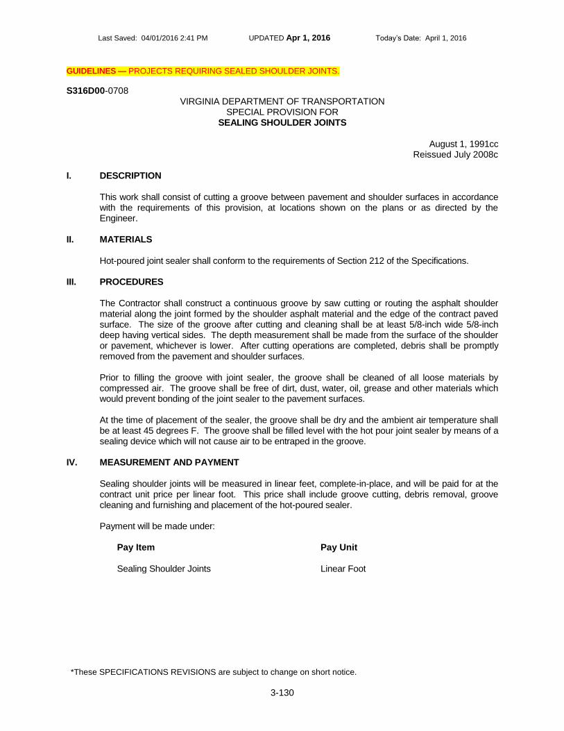
Last Saved: 04/01/2016 2:41 PM UPDATED Apr 1, 2016 Today’s Date: April 1, 2016
*These SPECIFICATIONS REVISIONS are subject to change on short notice.
3-130
GUIDELINES — PROJECTS REQUIRING SEALED SHOULDER JOINTS.
S316D00-0708 VIRGINIA DEPARTMENT OF TRANSPORTATION
SPECIAL PROVISION FOR SEALING SHOULDER JOINTS
August 1, 1991cc
Reissued July 2008c I. DESCRIPTION
This work shall consist of cutting a groove between pavement and shoulder surfaces in accordance with the requirements of this provision, at locations shown on the plans or as directed by the Engineer.
II. MATERIALS Hot-poured joint sealer shall conform to the requirements of Section 212 of the Specifications.
III. PROCEDURES The Contractor shall construct a continuous groove by saw cutting or routing the asphalt shoulder material along the joint formed by the shoulder asphalt material and the edge of the contract paved surface. The size of the groove after cutting and cleaning shall be at least 5/8-inch wide 5/8-inch deep having vertical sides. The depth measurement shall be made from the surface of the shoulder or pavement, whichever is lower. After cutting operations are completed, debris shall be promptly removed from the pavement and shoulder surfaces. Prior to filling the groove with joint sealer, the groove shall be cleaned of all loose materials by compressed air. The groove shall be free of dirt, dust, water, oil, grease and other materials which would prevent bonding of the joint sealer to the pavement surfaces. At the time of placement of the sealer, the groove shall be dry and the ambient air temperature shall be at least 45 degrees F. The groove shall be filled level with the hot pour joint sealer by means of a sealing device which will not cause air to be entraped in the groove.
IV. MEASUREMENT AND PAYMENT Sealing shoulder joints will be measured in linear feet, complete-in-place, and will be paid for at the contract unit price per linear foot. This price shall include groove cutting, debris removal, groove cleaning and furnishing and placement of the hot-poured sealer. Payment will be made under:
Pay Item
Pay Unit
Sealing Shoulder Joints Linear Foot

Last Saved: 04/01/2016 2:41 PM UPDATED Apr 1, 2016 Today’s Date: April 1, 2016
*These SPECIFICATIONS REVISIONS are subject to change on short notice.
3-131
GUIDELINES — ALL PROJECTS REQUIRING CLEARING AND GRUBBING.
SS30101-0914 September 3, 2014
VIRGINIA DEPARTMENT OF TRANSPORTATION 2007 ROAD AND BRIDGE SUPPLEMENTAL SPECIFICATIONS
SUPPLEMENTAL SECTION 301—CLEARING AND GRUBBING
SECTION 301—CLEARING AND GRUBBING of the Specifications is amended as follows:
Section 301.02—Procedures is amended to replace the second paragraph with the following:
The surface area of earth material exposed by grubbing, stripping topsoil, or excavation shall be limited to that necessary to perform the next operation within a given area. Grubbing of root mat and stumps shall be confined to that area of land which excavation or other land disturbance activities shall be performed by the Contractor within 14 days following grubbing.

Last Saved: 04/01/2016 2:41 PM UPDATED Apr 1, 2016 Today’s Date: April 1, 2016
*These SPECIFICATIONS REVISIONS are subject to change on short notice.
3-132
GUIDELINES — FOR PROJECTS REQUIRING DRAINAGE STRUCTURES.
SS30204-0613 March 14, 2013
VIRGINIA DEPARTMENT OF TRANSPORTATION 2007 ROAD AND BRIDGE SUPPLEMENTAL SPECIFICATIONS
SUPPLEMENTAL SECTION 302—DRAINAGE STRUCTURES
SECTION 302—DRAINAGE STRUCTURES of the Specifications is amended as follows:
Section 302.03(b) Precast Drainage Structures is amended to replace the second paragraph with the following:
Requests for approval of a precast design shall include detailed plans and supporting computations that have been reviewed by a registered Professional Engineer having at least 5 years experience in structural design of precast structures or components proposed and licensed in the Commonwealth. Unless otherwise specified, concrete exposed to freeze/thaw environments shall conform to Section 217.02 of the Specifications and shall have a design strength at 28 days of at least 4,000 pounds per square inch and an air content of 6 ± 2 percent. Concrete not exposed to freeze/thaw environments shall be exempt from the requirements of Section 217.02(a) of the Specifications. The design of the concrete mixture and the method of casting, curing handling and erecting of precast units shall be subject to review by the Engineer. Precast units may be shipped after reaching 85 percent of the design strength as determined by control cylinders. Sampling and testing concrete strength shall be performed using control cylinders in accordance with ASTM C31 and C39 at a rate of one set of cylinders per lot. A lot is defined as a maximum 250 cubic yards or a single weeks production (whichever quantity is less) of precast concrete from each batching operation, being of like material, strength and manufactured by the same process. Variations of lot definition will be governed by applicable specifications and approved by the Engineer. Control cylinders used for acceptance testing shall be cured under the same conditions as the concrete the cylinders represent. Units shall retain their structural integrity during shipment and shall be subject to inspection at the job site. Approval to use precast units shall not be construed as waiving the size and weight limitations specified in Section 107.21 of the Specifications.
Section 302.03(b)2. Precast arches is replaced with the following:
2. Precast arches shall conform to the applicable requirements of the current AASHTO’s LRFD
Bridge Design Specifications and VDOT modifications (current VDOT I&IM-S&B-80) and the following modifications: a. Protection against corrosion: The concrete cover of reinforcement shall be at least 1 1/2
inches.
Reinforcing steel for arches in 0 to 2 foot fills, in corrosive or marine environments, or in other severe exposure conditions shall be corrosion resistant reinforcing steel, Class I. When corrosion resistant reinforcing steel is required, the minimum cover specified shall not be reduced.
Exposed reinforcing bars, inserts, and plates intended for bonding with future extensions shall be protected from corrosion as directed by the Engineer.

Last Saved: 04/01/2016 2:41 PM UPDATED Apr 1, 2016 Today’s Date: April 1, 2016
*These SPECIFICATIONS REVISIONS are subject to change on short notice.
3-133
Reinforcement shall be designed and detailed in consideration of fabrication and construction tolerances so that the minimum required cover and proper positioning of reinforcement shall be maintained.
b. Anchorage: Sufficient anchorage shall be provided at the terminus of lines of precast units.
Anchorage may consist of a cast-in-place end section at least 3 feet in length with a headwall or collar around the precast unit(s) provided adequate connection can be made between the collar and units.
c. Joints: Joints between units shall be sealed by preformed plastic or mastic gaskets or grout.
When preformed gaskets are used, they shall be of a type listed on the Department’s approved products list.
d. Pipe openings: Pipe openings will not be allowed in the precast arch but may be provided
through the wingwalls. When required, openings shall conform to the requirements of (b)1.b. herein.
Section 302.03(b)3. Precast box culverts is replaced with the following:
3. Precast box culverts shall conform to the applicable requirements of the current AASHTO’s
LRFD Bridge Design Specifications and VDOT modifications (current VDOT I&IM-S&B-80) and the following modifications:
a. Precast Box Culverts shall conform to the applicable material requirements of ASTM C1577.
The design shall be a Special Design which need not conform to the reinforcing steel and geometry shown in the design tables and the appendix in ASTM C1577.
b. For protection against corrosion, the following minimum concrete cover shall be provided for
reinforcement: For boxes with more than 2 feet of fill over the top slab: 1 1/2 inches. For boxes with less than 2 feet of fill over the top slab: top reinforcement of top slab: 2 1/2 inches; bottom reinforcement of top slab: 2 inches; all other reinforcement: 1 1/2 inches.
Reinforcing steel for arches in 0 to 2 foot fills, in corrosive or marine environments, or in other severe exposure conditions shall be corrosion resistant reinforcing steel, Class I. When corrosion resistant reinforcing steel is required, the minimum cover specified shall not be reduced.
c. The type of sealant used in joints between units shall be from the Department’s Approved
List of Preformed Plastic or Mastic Gaskets.
Where double or greater lines of precast units are used, a buffer zone of 3 to 6 inches between lines shall be provided. This buffer zone shall be backfilled with porous backfill conforming to the requirements of Section 204. The porous backfill shall be drained by a 3-inch-diameter weep hole, formed by non-rigid tubing, located at the top of the bottom haunch, centered in the outlet end section and at approximately 50-foot intervals along the length of the box. Weep holes shall be covered with a 3-foot-square section of filter barrier cloth firmly attached to the outside of the box. A 3-foot width of filter barrier cloth shall also be centered over the buffer zone for the entire length of the structure after placement of the porous backfill material. Filter barrier cloth shall conform to the requirements of Section 245.
Forming weep holes and furnishing and placing of the filter barrier cloth shall be included in the price bid per linear foot for the precast box culvert.
d. At the terminus of precast units, sufficient anchorage shall be provided. This anchorage may
consist of a cast-in-place end section at least 3 feet in length with a headwall and curtain

Last Saved: 04/01/2016 2:41 PM UPDATED Apr 1, 2016 Today’s Date: April 1, 2016
*These SPECIFICATIONS REVISIONS are subject to change on short notice.
3-134
wall or a collar cast-in-place around the units provided adequate connection can be made between the collar and units.
When the ends of precast units are skewed, the end section shall be cast monolithically. The skew may be provided by forming, saw cutting, or other methods approved by the Engineer. Regardless of the method used, the variation in the precast unit from the exact skew shall be not greater than 1 1/2 inches at any point.
e. Pipe openings shall conform to the requirements of 1.b. herein. f. Bedding and backfill shall be in accordance with Standard PB-1 for box culverts.
Section 302.03 Procedures is amended to add the following
(d) Post Installation Inspection In addition to the visual inspection performed by the Department during the initial installation of storm sewer pipes and pipe culverts, a post installation visual/video camera inspection shall be conducted by the Contractor in accordance with the requirements of this specification and VTM 123 on all storm sewer pipe and a selected number of pipe culverts. For the purposes of this Section, a storm sewer pipe is defined as either a component of a storm sewer system as defined in Section 101.02 of the Specifications or any pipe identified on the plans as storm sewer pipe. All other pipe shall be considered pipe culverts. Post installation Inspections shall be performed on straight line and radial installations. For pipe culverts, a minimum of one pipe installation for each size of each material type utilized on the project will be randomly selected by the Engineer for inspection, however, in no case will the amount of pipe subject to inspection be less than ten percent of the total contract amount for the size and material type indicated. Where possible, for all installations in which the pipe or culvert’s size, orientation, or location permit deflection to be easily visually identified, (as verified with the Engineer) the Contractor may perform visual inspections in lieu of video inspections. If defects as described herein are noted during the inspection, the Engineer may require additional pipe installations of that size and/or material be inspected. The Contractor shall coordinate and schedule all post installation inspections so that these are made in the presence of the Engineer. The post installation inspection shall be performed no sooner than 30 days after completion of the pipe installation and placement of final cover (except for pavement structure). The Contractor shall issue a report detailing all issues or deficiencies noted during the inspection (including a remediation plan for each deficiency noted where applicable) no later than 5 days after completion of the inspection. While the intent of this requirement is to perform the post installation inspection prior to paving, project scheduling may dictate that a particular site be paved before the end of the 30 day period. In such cases, a preliminary inspection of the pipe shall be made, prior to paving over it, to insure that the pipe has been properly installed and is performing well. Performing such a preliminary inspection prior to paving will not relieve the Contractor from the requirement to perform the post installation inspection after the 30 day period. The Contractor’s inspection report shall identify and address any of the following items observed during the post installation inspection including identifying any proposed remediation measures the Contractor plans to perform where applicable. Remediation measures may consist of repairing or replacing the defective pipe section(s) or a combination of the two where differing conditions exist within the same run of pipe.

Last Saved: 04/01/2016 2:41 PM UPDATED Apr 1, 2016 Today’s Date: April 1, 2016
*These SPECIFICATIONS REVISIONS are subject to change on short notice.
3-135
Where permitted as an option, remediation methods for the various installation defects shall be proposed by the Contractor, reviewed with the Engineer and must have the Engineer’s approval prior to implementation of the corrective action. Remediation shall be the sole responsibility of the Contractor. Further, if remediation measures are shown to be necessary, any time associated with such measures shall be reflected in the impact to the Contractor’s progress schedule (may take the form of a time impact analysis, where required by the scheduling requirements) and will not relieve the Contractor of his responsibilities to finish the work required by the contract within the contract time limits or form the basis for any claim of delay where such remediation measures are determined to be a result of the Contractor’s fault, omission or negligence. Upon completion of any corrective remedial measures, the corrected installations are to be re-inspected prior to final acceptance of the project utilizing the test methods identified in VTM 123. The following criteria shall form the basis for inspections for the respective pipe or culvert types listed:
1. Concrete Pipe\Culverts:
a. Misalignment: Vertical and horizontal alignment of the pipe culvert or storm drain pipe barrel shall be checked by sighting along the crown, invert and sides of the pipe, and by checking for sagging, faulting and invert heaving. For the purposes of this provision faulting is defined as differential settlement between joints of the pipe, creating a non-uniform profile of the pipe. The person assigned by the Contractor to perform the inspection should take into account pipe or culvert laid with a designed camber or grade change in accordance with project or site requirements. Horizontal alignment shall be checked for straightness or smooth curvature. Any issues involving incorrect horizontal and/or vertical alignment shall be noted in the inspection report. If any vertical and/or horizontal misalignment problems are visually noted by the Engineer or in the inspection report, a further evaluation shall be conducted by the Engineer to determine the impact of the misalignment on the joints and wall of the pipe to ascertain what corrective actions are needed. All corrective actions determined necessary by the Engineer that are a result of the Contractor’s negligence, omission or fault shall be the sole responsibility of the Contractor to remedy.
b. Joints: Leaking joints may be detected during low flows by visual observation of the joints or checking around the ends of pipes or culverts for evidence of piping or seepage. Differential movement, cracks, spalling, improper gasket placement, movement or settlement of pipe\culvert sections, and leakage shall be noted by the Contractor in the report. Joint separation greater than one inch shall be remediated by the Contractor at his expense to the satisfaction of the Engineer. . Evidence of soil migration through the joint will be further evaluated by the Engineer to determine the level of corrective action necessary. All corrective actions determined necessary by the Engineer that are a result of the Contractor’s negligence, omission or fault shall be the sole responsibility of the Contractor to remedy.

Last Saved: 04/01/2016 2:41 PM UPDATED Apr 1, 2016 Today’s Date: April 1, 2016
*These SPECIFICATIONS REVISIONS are subject to change on short notice.
3-136
c. Cracks: Longitudinal cracks with a width less than one hundredth of an inch (0.01) are considered hairline and minor. They shall be noted in the inspection report; however, no remedial action is necessary. Longitudinal cracks having a width equal to or greater than one hundredth of an inch (0.01 but equal to or less than one tenth of an inch (0.1) and determined by the Engineer to be detrimental to the structure shall be sealed by a method proposed by the pipe\culvert manufacturer and approved by the Engineer. Pipes or culverts having longitudinal cracks with widths greater than one tenth of an inch (0.1) and determined to be beyond the limits of a satisfactory structural repair shall be replaced by the Contractor at his expense to the satisfaction of the Engineer. Pipes or culverts having displacement across the crack greater than 0.1 inch but less than 0.3 inch shall be remediated. Remediation methods shall be in accordance with recommendations of the pipe or culvert manufacturer, be acceptable to and authorized by the Engineer before implementation and shall be the sole responsibility of the Contractor. Pipes\culverts having displacement across the crack greater than 0.3 inch shall be replaced by the Contractor at his expense to the satisfaction of the Engineer. Transverse cracks will be evaluated using the same criteria as indicated above for longitudinal cracks.
d. Spalls: Spalling is defined as a localized pop-out of concrete along the wall of the pipe\culvert generally caused by corrosion of the steel reinforcement or at the edges of longitudinal or circumferential cracks. Spalling may be detected by visual examination of the concrete along the edges of the crack. The person conducting the inspection shall check for possible delamination. If delamination is noted or if a hollow sound is produced when the area is tapped with a device such as a hammer, the pipe\culvert shall be remediated. Remediation methods shall be in accordance with recommendations of the pipe\culvert manufacturer, be acceptable to and authorized by the Engineer before proceeding, and shall be the sole responsibility of the Contractor.
e. Slabbing: Any pipe\culvert experiencing slabbing shall be remediated. Slabbing is a structural failure of the pipe\culvert that results from radial or diagonal tension forces in the pipe\culvert. These failures appear as a separation of the concrete from the reinforcing steel near the crown or invert of the pipe\culvert and may span the entire length of a pipe or culvert section (joint to joint). Remediation methods shall be in accordance with recommendations of the pipe or culvert manufacturer, be acceptable to and authorized by the Engineer before proceeding, and shall be the sole responsibility of the Contractor. Where slabbing is of such magnitude that, in the opinion of the Engineer the integrity or service life of the pipe or culvert is severely compromised, the section(s) of pipe or culvert exhibiting such deficiency shall be replaced at the Contractor’s expense to the satisfaction of the Engineer.
2. Thermoplastic Pipe\Culvert: a. Misalignment: Vertical and horizontal alignment of the pipe culvert or
storm drain pipe barrel(s) shall be checked by sighting along the crown,

Last Saved: 04/01/2016 2:41 PM UPDATED Apr 1, 2016 Today’s Date: April 1, 2016
*These SPECIFICATIONS REVISIONS are subject to change on short notice.
3-137
invert and sides of the pipe, and by checking for sagging, faulting and invert heaving. The person assigned by the Contractor to perform the inspection should take into account pipes\culverts laid with a designed camber or grade change. Horizontal alignment shall be checked for straightness or smooth curvature. Any issues with horizontal and/or vertical alignment shall be noted in the inspection report. If any vertical and/or horizontal misalignment problems are noted in the inspection, a further evaluation will be performed by the Engineer to determine the impact of the misalignment on the joints and wall of the pipe\culvert to ascertain what corrective actions are needed. All corrective actions determined necessary by the Engineer that are a result of the Contractor’s negligence, omission or fault shall be the sole responsibility of the Contractor to remedy.
b. Cracks: Cracks or splits in the interior wall of the pipe shall be
remediated. Remediation methods shall be in accordance with recommendations of the pipe manufacturer, be acceptable to and authorized by the Engineer before proceeding, and shall be the sole responsibility of the Contractor
c. Joints: Pipes\culverts showing evidence of crushing at the joints shall be remediated. Differential movement, improper joint sealing, movement or settlement of pipe\culvert sections, and leakage shall be noted in the inspection report. Joint separation of greater than 1 inch shall be remediated. Evidence of soil migration through the joint will be further investigated by the Engineer to determine the level of remedial action required by the Contractor. Remediation methods shall be in accordance with recommendations of the pipe manufacturer, be acceptable to and authorized by the Engineer before proceeding. All corrective actions determined necessary by the Engineer that are a result of the Contractor’s negligence, omission or fault shall be the sole responsibility of the Contractor to remedy.
d. Buckling, bulging, and racking: Flat spots or dents at the crown, sides
or flow line of the pipe due to racking shall be noted in the inspection report and will be evaluated by the Engineer. Areas of wall buckling and bulging shall also be noted in the inspection report and evaluated by the Engineer for corrective action if deemed necessary by the Engineer. All corrective actions determined necessary by the Engineer shall be the sole responsibility of the Contractor.
e. Deflection: Any one of several methods may be used to measure
deflection of thermoplastic pipe\culvert (laser profiler, mandrel, direct manual measure, etc.) If the initial inspection indicates the pipe\culvert has deflected 7.5 percent or more of its original diameter, and if the original inspection was performed using a video camera, then a mandrel test shall also be performed in accordance with VTM 123. All deflections shall be noted in the inspection report. Deflections of less than 5 percent of the original pipe\culvert’s diameter shall not require remediation. Deflection of 5 percent up to 7.4 percent will be evaluated by the Engineer. If the pipe\culvert experiences additional defects along with deflection of 5 percent up to 7.4 percent of the original pipe\culvert’s diameter, the pipe\culvert shall be remediated. Remediation methods shall be in accordance with recommendations of the pipe\culvert

Last Saved: 04/01/2016 2:41 PM UPDATED Apr 1, 2016 Today’s Date: April 1, 2016
*These SPECIFICATIONS REVISIONS are subject to change on short notice.
3-138
manufacturer, be acceptable to and authorized by the Engineer before proceeding, and shall be the sole responsibility of the Contractor. If the pipe\culvert is deflected 7.5 percent or greater of the original diameter, the pipe\culvert shall be replaced by the Contractor at his expense to the satisfaction of the Engineer In lieu of the options noted above for remediation of deflection in thermoplastic pipe\culvert installations, the Contractor may elect to follow the payment schedule below:
Amount of Deflection Percent of Payment
0.0 % TO 5.0% 100% of Unit Bid Price
5.1% to 7.5% 75% of Unit Bid Price
Greater than 7.5% Remove and Replace at Contractor’s Expense
Remediation efforts and payment shall apply to the entire section(s) of the deflected pipe or culvert, joint to joint.
3. Metal Pipe\Culvert:
a. Misalignment: Vertical and horizontal alignment of the pipe culvert or storm drain pipe barrel shall be checked by sighting along the crown, invert and sides of the pipe\culvert, and by checking for sagging, faulting and invert heaving. The person assigned by the Contractor to perform the inspection should take into account pipe laid with a designed camber or grade change. Horizontal alignment shall be checked for straightness or smooth curvature. Any issues with horizontal and/or vertical alignment shall be noted in the inspection report for evaluation by the Engineer. If any vertical and/or horizontal misalignment problems are noted in the inspection, further evaluation will be conducted by the Engineer to determine the impact of the misalignment on the joints and wall of the pipe\culvert to ascertain what corrective actions by the Contractor are needed. All corrective actions determined necessary by the Engineer that are a result of the Contractor’s negligence, omission or fault shall be the sole responsibility of the Contractor to remedy.
b. Buckling, bulging, and racking: Flat spots or dents at the crown, sides or flow line of the pipe due to racking shall be noted by the Contractor’s inspector in the inspection report and will be evaluated by the Engineer for possible remediation by the Contractor. Areas of wall buckling and bulging shall also be noted in the inspection report and evaluated by the Engineer for possible remediation by the Contractor. If the Engineer determines corrective actions are necessary they shall be in accordance with the pipe\culvert manufacturer’s recommendations, be acceptable to and authorized by the Engineer prior to implementation and be the sole responsibility of the Contractor.
c. Joints: Pipes showing evidence of crushing at the joints shall be remediated. Differential movement, improper joint sealing, movement or settlement of pipe sections, and leakage shall be noted in the report. Joint separation of greater than 1.0 inch shall be remediated. Evidence of soil migration through the joint will be further investigated by the Engineer to determine the level of remedial action required by the
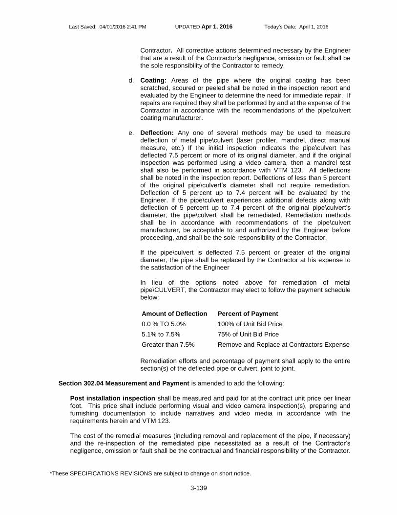
Last Saved: 04/01/2016 2:41 PM UPDATED Apr 1, 2016 Today’s Date: April 1, 2016
*These SPECIFICATIONS REVISIONS are subject to change on short notice.
3-139
Contractor. All corrective actions determined necessary by the Engineer that are a result of the Contractor’s negligence, omission or fault shall be the sole responsibility of the Contractor to remedy.
d. Coating: Areas of the pipe where the original coating has been scratched, scoured or peeled shall be noted in the inspection report and evaluated by the Engineer to determine the need for immediate repair. If repairs are required they shall be performed by and at the expense of the Contractor in accordance with the recommendations of the pipe\culvert coating manufacturer.
e. Deflection: Any one of several methods may be used to measure deflection of metal pipe\culvert (laser profiler, mandrel, direct manual measure, etc.) If the initial inspection indicates the pipe\culvert has deflected 7.5 percent or more of its original diameter, and if the original inspection was performed using a video camera, then a mandrel test shall also be performed in accordance with VTM 123. All deflections shall be noted in the inspection report. Deflections of less than 5 percent of the original pipe\culvert’s diameter shall not require remediation. Deflection of 5 percent up to 7.4 percent will be evaluated by the Engineer. If the pipe\culvert experiences additional defects along with deflection of 5 percent up to 7.4 percent of the original pipe\culvert’s diameter, the pipe\culvert shall be remediated. Remediation methods shall be in accordance with recommendations of the pipe\culvert manufacturer, be acceptable to and authorized by the Engineer before proceeding, and shall be the sole responsibility of the Contractor. If the pipe\culvert is deflected 7.5 percent or greater of the original diameter, the pipe shall be replaced by the Contractor at his expense to the satisfaction of the Engineer In lieu of the options noted above for remediation of metal pipe\CULVERT, the Contractor may elect to follow the payment schedule below:
Amount of Deflection Percent of Payment
0.0 % TO 5.0% 100% of Unit Bid Price
5.1% to 7.5% 75% of Unit Bid Price
Greater than 7.5% Remove and Replace at Contractors Expense
Remediation efforts and percentage of payment shall apply to the entire section(s) of the deflected pipe or culvert, joint to joint.
Section 302.04 Measurement and Payment is amended to add the following:
Post installation inspection shall be measured and paid for at the contract unit price per linear foot. This price shall include performing visual and video camera inspection(s), preparing and furnishing documentation to include narratives and video media in accordance with the requirements herein and VTM 123. The cost of the remedial measures (including removal and replacement of the pipe, if necessary) and the re-inspection of the remediated pipe necessitated as a result of the Contractor’s negligence, omission or fault shall be the contractual and financial responsibility of the Contractor.

Last Saved: 04/01/2016 2:41 PM UPDATED Apr 1, 2016 Today’s Date: April 1, 2016
*These SPECIFICATIONS REVISIONS are subject to change on short notice.
3-140
Payment will be made under:
Pay Item
Pay Unit
Post installation inspection Linear Foot
Section 302.04 Measurement and Payment is amended to add the following:
Epoxy-coated reinforcing steel, when a pay item, will be measured in pounds of uncoated steel and will be paid for at the contract unit price per pound. The weight will be computed from the theoretical weights of the nominal sizes of steel specified and placed in the structure. Measurement will not be made for epoxy-coating material. This price shall include furnishing steel and epoxy-coating material; applying coating material; fabricating, shipping, and placing epoxy-coated reinforcement in the structure; and necessary repairing of epoxy coatings. Payment will be made under:
Pay Item
Pay Unit
Epoxy-coated reinforcing steel Pound

Last Saved: 04/01/2016 2:41 PM UPDATED Apr 1, 2016 Today’s Date: April 1, 2016
*These SPECIFICATIONS REVISIONS are subject to change on short notice.
3-141
GUIDELINES — FOR PROJECTS REQUIRING EARTHWORK OR LAND DISTURBANCE ACTIVITIES.
SS30306-0914 September 3, 2014
VIRGINIA DEPARTMENT OF TRANSPORTATION 2007 ROAD AND BRIDGE SUPPLEMENTAL SPECIFICATIONS
SUPPLEMENTAL SECTION 303—EARTHWORK
SECTION 303—EARTHWORK of the Specifications is amended as follows:
Section 303.02—Materials is amended to add the following:
(e) Seed shall conform to Section 244.02(c) of the Specifications.
Section 303.03—Erosion and Siltation Control is amended to replace the title with Erosion and Siltation Control and Stormwater Pollution Prevention. Section 303.03—Erosion and Siltation Control is amended to replace the first three paragraphs with the following:
Erosion, siltation and stormwater pollution shall be controlled through the use of the devices and methods specified herein, identified in other contract documents or as is otherwise necessary. The Engineer reserves the right to require other temporary measures not specifically described herein or in other contract documents to correct an erosion, siltation or pollution condition. Erosion and sediment control and pollution prevention devices and measures shall be maintained in a functional condition at all times. Temporary and permanent erosion and sediment control and pollution prevention measures shall be inspected and deficiencies corrected in accordance with the requirements of Section 107.16(e) of the Specifications. In addition, the Contractor shall make a daily review of the location of silt fences, filter barriers and other perimeter controls to ensure that they are properly located for maximum effectiveness. Where deficiencies are found, corrections shall be made in accordance with the requirements of Section 107.16(e) of the Specifications or as directed by the Engineer. When erosion and sediment control devices function by using wet storage, sediments shall be removed when the wet storage volume has been reduced by 50 percent. Sediments shall be removed from dewatering basins when the excavated volume has been reduced by 50 percent. Sediments shall be removed from all other erosion and sediment control devices when capacity, height, or depth has been reduced by 50 percent. Removed sediment shall be disposed of in accordance with the requirements of Section 106.04 of the Specifications. Sediment deposits remaining in place after the device is no longer required shall be removed or dressed to conform to the existing grade. The site shall be prepared and seeded in accordance with the requirements of Section 603 of the Specifications.
Section 303.03(b) Soil Stabilization is replaced with the following:
(b) Soil Stabilization: Soil stabilization shall be initiated on any portion of the project where clearing, grading, excavation or other land disturbing activities have permanently ceased or where land disturbing activities have been temporarily suspended for an anticipated duration of greater than 14 days, or upon completion of grading operation for a specific area. Soil stabilization shall begin as soon as practicable but no later than the next business day (Monday through Friday excluding State holidays) following the day when land disturbing activities temporarily or permanently cease. Initiation of stabilization activities includes, but is

Last Saved: 04/01/2016 2:41 PM UPDATED Apr 1, 2016 Today’s Date: April 1, 2016
*These SPECIFICATIONS REVISIONS are subject to change on short notice.
3-142
not limited to 1) prepping the soil for vegetative or non-vegetative stabilization, 2) applying mulch or other non-vegetative product to exposed soil, 3) seeding or planting the exposed area 4) starting any of the above activities on a portion of the area to be stabilized but not on the entire area or 5) finalizing arrangements to have the stabilization product fully installed within the time frame for completing stabilization. Temporary or permanent soil stabilization shall be completed within 7 days after initiation. Areas excluded from this requirement include areas within 100 feet of the limits of ordinary high water or a delineated wetland which shall be continuously prosecuted until completed and stabilized immediately upon completion of the work in each impacted area. Soil stabilization includes: temporary and permanent seeding, riprap, aggregate, sod, mulching, and soil stabilization blankets and matting in conjunction with seeding. The applicable type of soil stabilization shall depend upon the location of areas requiring stabilization, time of year (season), weather conditions and stage of construction operations. Cut and fill slopes shall be shaped and topsoiled where specified. Seed and mulch shall be applied in accordance with the requirements of Section 603 of the Specifications as the work progresses in the following sequence: 1. Slopes whose vertical height is 20 feet or greater shall be seeded in three equal
increments of height. Slopes whose vertical height is more than 75 feet shall be seeded in 25-foot increments.
2. Slopes whose vertical height is less than 20 but more than 5 feet shall be seeded in two
equal increments. 3. Slopes whose vertical height is 5 feet or less may be seeded in one operation. Areas that cannot be seeded because of seasonal or adverse weather conditions shall be mulched to provide some protection against erosion to the soil surface. Mulch shall be applied in accordance with the requirements of Section 603.03(e) of the Specifications and paid for in accordance with the requirements of Section 603.04 of the Specifications. Organic mulch shall be used, and the area then seeded as soon as weather or seasonal conditions permit in accordance with the requirements of Section 603.03 of the Specifications. Organic mulch includes: straw or hay, fiber mulch, wood cellulose, or wood chips conforming to the requirements of Section 244.02(g) of the Specifications.
Section 303.03(f) Sediment Traps and Sediment Basins is replaced with the following: (f) Sediment Traps and Sediment Basins: Once a sediment trap or basin is constructed, the
earthen embankment and all outfall areas shall be stabilized immediately.
Section 303.03—Erosion and Siltation Control is amended to add the following:
(h) Temporary Diversion Dike: This work shall consist of constructing temporary diversion dikes at the locations designated on the plans and in accordance with the plan details and the Specifications, stabilizing with seed and mulch, maintaining, removing when no longer required, and restoration of the area. Temporary diversion dikes shall be installed as a first step in land-disturbing activities and shall be functional prior to downslope land disturbance. The dike shall be constructed to prevent failure in accordance with Section 303.04 of the Specifications. Seeding and mulch shall be applied to the dike in accordance with Section 603 of the Specifications immediately following its construction. The dikes should be located to minimize damages by construction operations and traffic.

Last Saved: 04/01/2016 2:41 PM UPDATED Apr 1, 2016 Today’s Date: April 1, 2016
*These SPECIFICATIONS REVISIONS are subject to change on short notice.
3-143
The Contractor shall inspect the temporary diversion dikes after every storm and repairs made to the dike, flow channel, outlet, or sediment trapping facility, as necessary. Once every two weeks, whether a storm event has occurred or not, the measure shall be inspected and repairs made if needed. Damages to the dikes caused by construction traffic or other activity must be repaired before the end of the working day.
Section 303.04(a)—Regular Excavation is amended to replace the last paragraph with the following:
Stripping topsoil shall be confined to the area over which grading is to be actively prosecuted within 14 calendar days following the stripping operation. Grading operations shall be confined to the minimum area necessary to accommodate the Contractor’s equipment and work force engaged in the earth moving work.
Section 303.06(e)—Erosion Control Items is amended to replace “4. Check dams” with the following:
4. Check dams will be paid for at the contract unit price per each. This price shall include
furnishing, excavating, constructing, maintaining, repositioning as may be required during construction and removing the check dams if, or when, no longer required.
Synthetic check dams may be substituted for Type II Rock Check dams (Standard EC-4) at no additional cost to the Department.
Section 303.06(e)—Erosion Control Items is amended to replace “6. Geotextile fabric” with the following:
6. Geotextile fabric attached to brush barriers or existing fence or used for another function
specified on the plans will be measured in square yards, complete-in-place, excluding laps, and will be paid for at the contract unit price per square yard. This price shall include trimming the brush barrier; furnishing, installing, maintaining, and removing the fabric; and dressing and stabilizing the area.
The brush barrier will not be measured for separate payment. The cost thereof shall be included in the price for clearing and grubbing.
Section 303.06(e)—Erosion Control Items is amended to replace “15. Drop Inlet Silt Trap” and its corresponding Pay Item and Pay Unit with the following:
15. Inlet protection:
a. Inlet Protection Type A will be measured in units of each and will be paid for at the
contract unit price per each location shown or specified. The price shall include furnishing and installing temporary filter barrier including posts and top rails, coarse aggregate and, if required, sediment forebay. This price shall also include maintenance and removal until no longer required. Inlet Protection Type A will be paid for only one time during the duration of the project.
b. Inlet Protection Type B will be measured in units of each and will be paid for at the
contract unit price per each location shown or specified. The price shall include furnishing and installing hardware mesh cloth, concrete blocks, wooden studs, coarse aggregate, and maintenance and removal until no longer required. Inlet Protection Type B will be paid for only one time during the duration of the project.

Last Saved: 04/01/2016 2:41 PM UPDATED Apr 1, 2016 Today’s Date: April 1, 2016
*These SPECIFICATIONS REVISIONS are subject to change on short notice.
3-144
c. Inlet Protection Type C will be measured and paid for in accordance with the individual pay items and pay units shown in the Standard Drawing for EC-6, Type C. The individual pay items for Inlet Protection Type C will be paid for only one time during the duration of the project for each location shown or specified
Payment will be made under:
Pay Item
Pay Unit
Inlet protection Type A Each Inlet protection Type B Each
Section 303.06(e)—Erosion Control Items is amended to add the following:
18. Temporary diversion dike will be measured in linear feet, complete-in-place, and will be
paid for at the contract unit price per linear foot. This price shall be full compensation for installing the diversion dike, stabilizing with seed and mulch, maintaining, removing when no longer required, and restoration of the area. Payment will be made under: Pay Item
Pay Unit
Temporary diversion dike Linear foot

Last Saved: 04/01/2016 2:41 PM UPDATED Apr 1, 2016 Today’s Date: April 1, 2016
*These SPECIFICATIONS REVISIONS are subject to change on short notice.
3-145
GUIDELINES — PROJECTS REQUIRING DENSITY CONTROL STRIPS.
SS30401-0911 April 27, 2011
VIRGINIA DEPARTMENT OF TRANSPORTATION 2007 ROAD AND BRIDGE SUPPLEMENTAL SPECIFICATIONS
SUPPLEMENTAL SECTION 304—CONSTRUCTING DENSITY CONTROL STRIPS
SECTION 304—CONSTRUCTING DENSITY CONTROL STRIPS of the Specifications is amended as follows:
Section 304.04—Procedures is amended to replace the second paragraph with the following:
One control strip shall be constructed at the beginning of work on each roadway and shoulder course and each lift of each course. An additional control strip shall be constructed when a change is made in the type or source of material or whenever a significant change occurs in the composition of the material from the same source. For subgrade and subbase materials, the maximum theoretical density from either one-point proctor test (VTM-12) or three point proctor tests (VTM-1) may be used in lieu of constructing a control strip, at the discretion of the Engineer.

Last Saved: 04/01/2016 2:41 PM UPDATED Apr 1, 2016 Today’s Date: April 1, 2016
*These SPECIFICATIONS REVISIONS are subject to change on short notice.
3-146
GUIDELINES — PROJECTS REQUIRING LIME STABILIZED ROADBED MATERIAL.
SS30601-0609 October 2, 2008
VIRGINIA DEPARTMENT OF TRANSPORTATION 2007 ROAD AND BRIDGE SUPPLEMENTAL SPECIFICATIONS
SUPPLEMENTAL SECTION 306—LIME STABILIZATION
SECTION 306—LIME STABILIZATION of the Specifications is amended as follows:
Section 306.01—Description is replaced with the following:
This work shall consist of stabilizing roadbed material by constructing one or more courses of the pavement structure using a mixture of soil or approved aggregates, lime or lime and fly ash, and water.
Section 306.02(b) Fly Ash is replaced with the following:
(b) Fly ash shall conform to the requirements of Section 241 of the Specifications. Bulk fly ash may be transported dry in bulk trucks and stored in tanks or may be transported in the dampened condition, with a maximum of 15 percent moisture, and stockpiled at the job site. Excessively wet or contaminated surface material shall not be used in mixing operations. Stockpiled material shall be covered with a non-absorptive cover material or periodically moistened to prevent moisture loss and becoming airborne.
Section 306.03—Procedures is amended to replace the opening paragraph with the following:
Lime stabilization will not be permitted when aggregate or the surface on which the course is to be placed is frozen. Manipulation shall not be started until the surface is free from mud and frost and the ambient air temperature is at least 40 degrees F.
Section 306.03(b) Preparing the Materials is replaced with the following:
(b) Preparing Materials: The prepared roadbed shall be scarified to the depth and width required for stabilization. The depth of scarification and the blading operation shall be controlled in such a manner that the surface of the roadbed below the scarified material shall remain undisturbed and shall conform to the established cross section. Prior to the beginning of stabilization work, material retained on the 3-inch sieve shall be removed.
Section 306.03(c) Applying Lime is amended to add following:
When applied in dry form, lime shall be spread uniformly over the top of the scarified material by an approved screw-type spreader box or other approved spreading equipment. The spreading operation shall be shrouded to minimize dust. Dry lime shall not be applied pneumatically, dropped from a dump truck, front end loader or bottom dumped. A motor grader shall not be used to spread the dry lime. Dry lime shall not be applied when, in the opinion of the Engineer, wind conditions are such that the blowing material would become objectionable to adjacent property owners or create potential hazards to traffic.
Section 306.03(d) Adding Water is replaced with the following:

Last Saved: 04/01/2016 2:41 PM UPDATED Apr 1, 2016 Today’s Date: April 1, 2016
*These SPECIFICATIONS REVISIONS are subject to change on short notice.
3-147
(d) Adding Water: Sufficient water shall be added by means of pressure water distributors or through the mixing chamber of a rotary mixer to provide moisture content at the time of compaction of not less than the optimum for the mixture no more than optimum +20 percent of optimum.
Section 306.03(e) Mixing is replaced with the following:
(e) Mixing: Lime and water shall be mixed throughout the scarified material as thoroughly as practicable using a self-propelled rotary mixer capable of mixing to a compacted depth of at least 12 inches. Disc harrows or motor graders shall not be used for mixing. The mixture shall then be spread over the roadbed. The surface shall be sealed with a steel wheel or pneumatic tire roller to retard the loss of moisture and then allowed to mellow for 4 to 48 hours. After mellowing, the lime-treated material shall be remixed with a rotary mixer until at least 60 percent of the material, exclusive of aggregates, will pass a No. 4 sieve. Additional water may be added, if necessary, during the remixing operations to ensure proper moisture for compaction. When a stationary mixer is used, the material may be placed, compacted, and finished immediately after mixing. When traveling plants are used, additional mixing with blades, tillers, discs, harrows, or repeated passes of the plant may be required. During the interval of time between lime application and initial mixing, lime that has been exposed to the open air for 6 hours or more, or lime that has been lost because of washing or blowing will not be measured for payment.
Section 306.03(f) Compacting and Finishing is replaced with the following:
(f) Compacting and Finishing: The mixture shall be placed and compacted to a density of at least 95 percent of the maximum density determined in accordance with the requirements of VTM-1 or VTM-12. Light sprinkling may be required during placement operations to maintain the specified moisture content. Compaction shall be accompanied by sufficient blading to eliminate irregularities. The surface shall be lightly scarified during finishing operations and bladed to eliminate imprints left by the equipment. Final rolling of the completed surface shall be accomplished with a pneumatic tire roller or steel wheel roller. Final compaction and finishing shall be completed within 12 hours after final mixing.
Section 306.03(g) Tolerances is replaced with the following:
(g) Tolerances: The finished stabilized course shall conform to the specified thickness, subject to the following tolerances: Thickness will be determined in accordance with the requirements of VTM-38A. Areas that are deficient in thickness by more than 1 inch shall be removed or reworked with an additional amount of lime equal to 50 percent of the original amount. In the case of stabilized base courses, the Contractor may correct sections deficient in depth by applying asphalt concrete provided such correction is authorized by the Engineer. Areas that are excessive in thickness by more than 2 inches shall be reworked, and an amount of lime equal to 50 percent of the original amount added to the mixture. Any replacement, corrective work and additional lime required to address deficiencies shall be at the Contractor’s expense.
Section 306.03(h) Protecting and Curing is replaced with the following:

Last Saved: 04/01/2016 2:41 PM UPDATED Apr 1, 2016 Today’s Date: April 1, 2016
*These SPECIFICATIONS REVISIONS are subject to change on short notice.
3-148
(h) Protecting and Curing: After finishing of the subgrade, no vehicles except sprinkling equipment shall be permitted on the subgrade for a curing period of 7 days or until the next course is placed, whichever is less. During the curing period, the subgrade shall be lightly sprinkled with water at frequent intervals to prevent the surface from drying and cracking. The Contractor shall plan and execute the work in such a manner as to place the next course during the curing period. If the Contractor has not placed the next course by the end of the curing period, he shall apply liquid asphalt and cover material at the rate specified on the plans. Damage to the stabilized course attributable to other phases of construction by the Contractor shall be repaired at the Contractor’s expense. At least one subsequent course shall be constructed on the stabilized course before hauling operations for the other phases of construction are permitted on the treated course. If the material loses the required stability, density, or finish before the next course is placed or the work accepted, it shall be recompacted and refinished at the Contractor’s expense.
Last Saved: 04/01/2016 2:41 PM UPDATED Apr 1, 2016 Today’s Date: April 1, 2016
*These SPECIFICATIONS REVISIONS are subject to change on short notice.
3-149
GUIDELINES —PROJECTS REQUIRING REGULAR OR NON-TRACKING TACK.
SS31001-1215 December 4, 2015
VIRGINIA DEPARTMENT OF TRANSPORTATION 2007 ROAD AND BRIDGE SUPPLEMENTAL SPECIFICATIONS
SUPPLEMENTAL SECTION 310—TACK COAT
SECTION 310—TACK COAT of the Specifications is completely replaced with the following: 310.01—Description This work shall consist of preparing and treating an existing asphalt or concrete surface with asphalt in accordance with these specifications and in conformity with the lines shown on the plans or as established by the Engineer. 310.02—Materials
(a) Tack Coat asphalt tack coat shall be CQS-1h, CRS-1h, or CSS-1h conforming to Section 210 of the Specifications. Asphalt emulsion CMS-2 conforming to Section 210 of the Specifications may be used during the winter months.
(b) Non-Tracking Tack Coat liquefied asphalt shall be selected from the Materials Division
Approved Products List 50.1A. The Contractor shall not dilute non-tracking tack coat materials with water.
310.03—Procedures The existing surface shall be patched, cleaned, and rendered free from irregularities to the extent necessary to provide a reasonably smooth and uniform surface. The Contractor shall remove unstable corrugated areas, and replace with suitable patching materials when required by the contract specifications. The Contractor shall clean the edges of existing pavements that are to be adjacent to new pavement to permit adhesion of asphalt. The Contractor shall uniformly apply tack coat or non-tracking tack coat material with a pressure distributor conforming to Section 314.04(b) of the Specifications. Hand spray equipment shall not be used except in areas inaccessible by a pressure distributor. The distributor shall be calibrated by the Contractor in the presence of the Engineer prior to initial asphalt plant mix placement to demonstrate an even and accurate spray application. Calibration will be considered acceptable when the spray rate is uniform and within 0.02 gallon per square yard of the design application rate. All tack coat and non-tracking tact coat materials stored longer than 30 days from the shipping date on the Bill of Lading shall be retested in accordance with Section 210.06 of the Specifications to verify the material still meets product specifications. Tack at joints, adjacent to curbs, gutters, or other appurtenances shall be applied with a hand wand or with spray bar at the rate of 0.2 gallon per square yard. At joints, the tack applied by the hand wand or a spray bar shall be 2 feet in width with 4 to 6 inches protruding beyond the joint for the first pass. Tack for

Last Saved: 04/01/2016 2:41 PM UPDATED Apr 1, 2016 Today’s Date: April 1, 2016
*These SPECIFICATIONS REVISIONS are subject to change on short notice.
3-150
the adjacent pass shall completely cover the vertical face of the pavement mat edge so that slight puddling of asphalt occurs at the joint, and extend a minimum of one foot into the lane to be paved. Care shall be taken to prevent spattering adjacent items during the application of tack coat. The distributor shall not be cleaned or discharged into ditches or borrow pits, onto shoulders, or along the right of way. When not in use, the Contractor shall ensure equipment is parked so that the spray bar or mechanism will not drip asphalt on the surface of the traveled way. The tack coat or non-tracking tack coat shall be applied to the pavement surface in such a manner that it will bond the overlay and the underlying surfaces together. The Contractor shall apply tack coat and non-tracking tack coat in accordance with the weather limitations that apply to the course being placed as well as the manufacturer’s recommendations. The Engineer will verify, and reserves the right to alter, the quantity, rate of application, temperature, and areas to be treated prior to application. The tack coat or non-tracking tack coat shall be applied in a manner to offer the least inconvenience to traffic and to permit one-way traffic without pick up or tracking of the asphalt onto adjacent non-treated areas. All traffic, including construction traffic, shall be excluded from tacked sections until the tack has cured. Tack shall not be required atop asphalt stabilized open-graded material drainage layers. The contractor shall measure and report to the agency on forms provided by the Engineer, the rate of tack material applied on a daily basis using VTM-137 Method B (Tack Yield Method). The Engineer shall verify the desired tack application rate is achieved using VTM-137 Method A (Tack Plate Method). This test shall be performed at a minimum frequency of once per each roadway, within the first 500 tons of asphalt mix placed, unless otherwise approved by the Engineer. The Engineer reserves the right to perform the tack plate method testing at a higher frequency, as determined necessary, to ensure adherence to specifications.
(a) Tack Coat Equipment for heating and applying asphalt shall conform to Section 314.04(b) of the Specifications. The maximum application temperature of liquid asphalt shall conform to Table III-1.
TABLE III-1
Liquid Asphalt Application Temperature
Type Max. Temperature (oF)
RC-70 180 RC-250 220 RC-800 225 RC-3000 290 MC-70 180 MC-250 220 MC-800 255 MC-3000 290 AC-5 300 AC-10 300
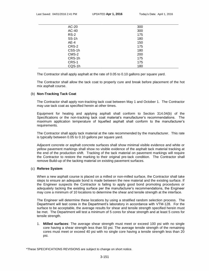
Last Saved: 04/01/2016 2:41 PM UPDATED Apr 1, 2016 Today’s Date: April 1, 2016
*These SPECIFICATIONS REVISIONS are subject to change on short notice.
3-151
AC-20 300 AC-40 300 RS-2 175 SS-1h 180 AE-4 150 CRS-2 175 CSS-1h 180 CMS-2 200 CRS-1h 175 CRS-1 175 CQS-1h 180
The Contractor shall apply asphalt at the rate of 0.05 to 0.10 gallons per square yard. The Contractor shall allow the tack coat to properly cure and break before placement of the hot mix asphalt course.
(b) Non-Tracking Tack Coat
The Contractor shall apply non-tracking tack coat between May 1 and October 1. The Contractor may use tack coat as specified herein at other times. Equipment for heating and applying asphalt shall conform to Section 314.04(b) of the Specifications or the non-tracking tack coat material’s manufacturer’s recommendations. The maximum application temperature of liquefied asphalt shall conform to the manufacturer’s requirements. The Contractor shall apply tack material at the rate recommended by the manufacturer. This rate is typically between 0.05 to 0.10 gallons per square yard. Adjacent concrete or asphalt concrete surfaces shall show minimal visible evidence and white or yellow pavement markings shall show no visible evidence of the asphalt tack material tracking at the end of the production shift. Tracking of the tack material on pavement markings will require the Contractor to restore the marking to their original pre-tack condition. The Contractor shall remove Build-up of the tacking material on existing pavement surfaces.
(c) Referee System
When a new asphalt course is placed on a milled or non-milled surface, the Contractor shall take steps to ensure an adequate bond is made between the new material and the existing surface. If the Engineer suspects the Contractor is failing to apply good bond promoting procedures or adequately tacking the existing surface per the manufacturer’s recommendations, the Engineer may core a minimum of 10 locations to determine the shear and tensile strength at the interface. The Engineer will determine these locations by using a stratified random selection process. The Department will test cores in the Department’s laboratory in accordance with VTM-128. For the surface to be acceptable, the average results for shear and tensile strength specified herein must be met. The Department will test a minimum of 5 cores for shear strength and at least 5 cores for tensile strength. 1. Milled surfaces: The average shear strength must meet or exceed 100 psi with no single
core having a shear strength less than 50 psi. The average tensile strength of the remaining cores must meet or exceed 40 psi with no single core having a tensile strength less than 20 psi.

Last Saved: 04/01/2016 2:41 PM UPDATED Apr 1, 2016 Today’s Date: April 1, 2016
*These SPECIFICATIONS REVISIONS are subject to change on short notice.
3-152
2. Un-milled surfaces: The average shear strength must meet or exceed 50 psi with no single core having a shear strength less than 30 psi. The average tensile strength of the remaining cores must meet or exceed 30 psi with no single core having a tensile strength less than 20 psi.
The Engineer will reduce the payment for the asphalt concrete tonnage placed in the area of dispute by 10 percent if the minimum shear or tensile strength requirements in that area are not met.
310.04—Measurement and Payment Tack coat, including Tack Coat and Non-Tracking Tack Coat materials, when a pay item, will be measured in gallons and will be paid for at the contract unit price per gallon. On a daily basis, the Contractor shall provide the Engineer readings taken from the calibrated distributor establishing the quantity of gallons placed for that day. Quantity for payment will be based on volume and temperature corrections in accordance with Section 109 of the Specifications. When not a pay item the Contractor shall include the cost in the contract unit price for other appropriate items.
Payment will be made under:
Pay Item
Pay Unit
Tack coat Gallon

Last Saved: 04/01/2016 2:41 PM UPDATED Apr 1, 2016 Today’s Date: April 1, 2016
*These SPECIFICATIONS REVISIONS are subject to change on short notice.
3-153
GUIDELINES — PROJECTS REQUIRING SUPERPAVE ASPHALT CONCRETE PAVEMENT. WHEN THIS
PROVISION APPLIES INCLUDE THE FOLLOWING IN THE PROPOSAL: SS21113 SuperPave -Asphalt Concrete and SS31001 Tack Coat.
SS31510-1214 December 2, 2014c
VIRGINIA DEPARTMENT OF TRANSPORTATION 2007 ROAD AND BRIDGE SUPPLEMENTAL SPECIFICATIONS
SUPPLEMENTAL SECTION 315—ASPHALT CONCRETE PLACEMENT
SECTION 315—ASPHALT CONCRETE PAVEMENT of the Specifications is replaced with the following:
315.01—Description This work shall consist of constructing one or more courses of asphalt concrete on a prepared foundation in accordance with the requirements of these specifications and within the specified tolerances for the lines, grades, thicknesses, and cross sections shown on the plans or established by the Engineer. At the Contractor’s option, the asphalt concrete mix may be produced using a warm-mix additive or warm-mix process approved by the Department. When used, the temperature placement limitations for Warm Mix Asphalt (WMA) shall apply. This work shall also consist of constructing asphalt concrete curb and rumble strips in accordance with the requirements of these specifications, plan details, and the Standard Drawings. 315.02—Materials
(a) Asphalt concrete shall conform to the requirements of Section 211. The Contractor shall
alter the design if SUPERPAVE design densities begin to exceed 98 percent of the theoretical maximum density during construction.
(b) Asphalt for Tack Coat Nontracking Tack will be required only between May 1 and
October 1. Tack coat, in accordance with Section 310 of the Specifications, may be used at other times. Asphalt for prime coat shall conform to the requirements in Section 311. Asphalt for Prime Coat may be changed one viscosity grade by the Engineer at no change in the contract unit price.
(c) Curb backup material shall be asphalt concrete conforming to any surface or
intermediate mixture listed in Table II-13 and Table II-14 of Section 211. (d) Liquid asphalt coating (emulsion) for rumble strips shall conform to the requirements
of Section 210. The Contractor shall use CSS-1h or CQS-1h asphalt emulsions conforming to Section 210 for centerline rumble strips. The CSS-1h or CQS-1h liquid asphalt may be diluted by up to 30 percent at the emulsion manufacturer’s facility.
315.03—Equipment
(a) Hauling Equipment: Trucks used for hauling asphalt mixtures shall have tight, clean,
smooth metal or other non-absorptive, inert material bodies equipped with a positive locking metal tailgate. Surfaces in contact with asphalt mixtures shall be given a thin coat of aliphatic hydrocarbon invert emulsion release agent (nonpuddling), a lime solution, or other release agent materials on the VDOT Materials Division Approved Products Listing

Last Saved: 04/01/2016 2:41 PM UPDATED Apr 1, 2016 Today’s Date: April 1, 2016
*These SPECIFICATIONS REVISIONS are subject to change on short notice.
3-154
(List No. 8). The beds of dump trucks shall be raised to remove excess release agent prior to loading except when a nonpuddling release agent is used. Only a nonpuddling agent shall be used in truck beds that do not dump. Each Contractor truck used for hauling asphalt shall be equipped with a tarpaulin or other cover acceptable to the Engineer that shall protect the mixture from moisture and foreign matter and prevent the rapid loss of heat during transportation.
(b) Asphalt Pavers: The asphalt paver shall be designed and recommended by the
manufacturer for the type of asphalt to be placed and shall be operated in accordance with the manufacturer’s recommendations. The Contractor shall readily have and maintain on the project site any written recommendations from the manufacturer of the mix relative to handling and placing of the mixture. In the absence of the manufacturer’s recommendations, the recommendations of the National Asphalt Pavement Association shall be followed. The paver shall be capable of producing a smooth uniform texture, dense joints, and a smooth riding surface even when screed extensions are used.
(c) Rollers: Rollers shall be steel wheel, static or vibratory, or pneumatic tire rollers and shall
be capable of reversing without backlash. The Contractor shall operate rollers at speeds slow enough to avoid displacement of the mixture. The number and weight of rollers shall be sufficient to compact the mixture to the required density while it is still in a workable condition. The Engineer will not allow the use of equipment that results in excessive crushing of aggregate or marring of the pavement surface. If during construction the Contractor’s equipment mars the surface of the pavement to the extent that imperfections cannot satisfactorily be corrected or produces permanent blemishes, the Engineer will require the Contractor to discontinue the use of that particular equipment and replace that equipment with satisfactory units.
(d) Rotary Saw: The Contractor shall supply a gasoline-powered rotary saw with a carbide
blade for cutting test samples from the pavement. The Contractor shall provide gasoline, oil, additional carbide blades, and maintenance for the rotary saw. The Contractor shall cool the pavement prior to sawing the sample. As an alternative, the Contractor may furnish the necessary equipment for coring and testing 4-inch core samples in accordance with the requirements of VTM-22.
(e) Material Transfer Vehicle (MTV): When required in the Contract, the Contractor shall
furnish a self-propelled MTV storage unit capable of receiving material from trucks, storing the material and transferring the material from the unit to the paver hopper or hopper insert via a conveyor system. The paver hopper insert and unit shall have a combined minimum storage capacity of 15 tons. The storage unit or paver hopper insert must be able to remix the material in order to produce a uniform, non-segregated mix having a uniform temperature prior to placing the asphalt material on the roadway surface.
315.04—Placement Limitations The Contractor shall not place asphalt concrete mixtures when weather or surface conditions are such that the material cannot be properly handled, finished, or compacted. The surface upon which asphalt mixtures is to be placed shall be free of standing water, dirt, and mud and the base temperature shall conform to the following:
(a) Asphalt Concrete Produced with Warm Mix Asphalt Additives or Processes: 1. When the base temperature is 40 degrees F and above: The Engineer will
permit laydown at any temperature below the maximum limits given in Section

Last Saved: 04/01/2016 2:41 PM UPDATED Apr 1, 2016 Today’s Date: April 1, 2016
*These SPECIFICATIONS REVISIONS are subject to change on short notice.
3-155
211.08 of the Specifications. The minimum base temperature for laydown shall be 40 degrees F, unless approved by the Engineer.
2. When the mixture temperature is below 200 degrees F, material shall not be permitted to be placed.
(b) Asphalt Concrete Produced without Warm Mix Asphalt Additives or Processes:
1. When the base temperature is above 80 degrees F: The Engineer will allow
laydown of the mixture at any temperature conforming to the limits specified in Section 211 of the Specifications.
2. When the base temperature is between 40 degrees F and 80 degrees F: The Contractor shall use the Nomograph, Table III-2, to determine the minimum laydown temperature of the asphalt concrete mixes. At no time shall the minimum base temperature for base (BM) and intermediate (IM) mixes be less than 40 degrees F. At no time shall the minimum laydown temperature for base (BM) and intermediate (IM) mixes be less than 250 degrees F. The minimum base and laydown temperatures for surface mixes (SM) shall never be less than the following:
PG Binder/Mix Designation
Percentage of Reclaimed Asphalt
Pavement (RAP) Added to Mix
Minimum Base Temperature
Minimum Placement
Temperature
PG 64S-22 (A) <=25% 40 oF 250
oF
PG 64S-22 (A) >25% 50 oF 270
oF
PG 64H-22 (D) <=30% 50 oF 270
oF
PG 64E-22 (E) <=15% 50 oF 290
oF
PG 64S-22 (S) <=30% 50 oF 290
oF
Intermediate and base courses that are placed at rates of application that exceed the application rates shown in Table III-2 shall conform to the requirements for the maximum application rate shown for 8-minute and 15-minute compaction rolling as per number of rollers used. If the Contractor is unable to complete the compaction rolling within the applicable 8-minute or 15-minute period, the Engineer will either require the placing of the asphalt mixture to cease until sufficient rollers are used or other corrective action be taken to complete the compaction rolling within the specified time period. The Contractor shall complete compaction rolling prior to the mat cooling down to 175 degrees F. Finish rolling may be performed at a lower mat temperature. The Contractor shall not place the final asphalt pavement finish course until construction (temporary) pavement markings will no longer be required.
315.05—Procedures

Last Saved: 04/01/2016 2:41 PM UPDATED Apr 1, 2016 Today’s Date: April 1, 2016
*These SPECIFICATIONS REVISIONS are subject to change on short notice.
3-156
(a) Base Course: The Contractor shall prepare the subgrade or subbase as specified in Section 305. The Contractor shall grade and compact the course to the required profile upon which the pavement is to be placed, including the area that will support the paving equipment.
(b) Conditioning Existing Surface: The Engineer will direct the Contractor to bring the
surface of the existing pavement or base to a uniform grade and cross section if they are irregular. Unless approved by the engineer, the uniform grade and cross section achieved shall be consistent with VDOT design standards for the roadway being paved. The surface on which the asphalt concrete is to be placed shall be prepared in accordance with the requirements of the applicable specifications and shall be graded and compacted to the required profile and cross section as established by VDOT design standards for the roadway being paved. When specified in the Contract, prior to placement of asphalt concrete the Contractor shall seal longitudinal and transverse joints and cracks by the application of an approved crack sealing material. Crack sealant for asphalt concrete pavement shall meet all the requirements of ASTM D-3405 and exceed all requirements of ASTM D-1190, AASHTO M-173 and Federal Specification SS-S-164: A hot-poured modified asphalt rubber with granulated crumb rubber and latex plasticizers. The proportions of the materials, by weight, shall be up to 80 percent maximum asphalt and up to 25 percent maximum crumb rubber. The crumb rubber shall be 100 percent vulcanized rubber and meet the following gradation requirement:
Sieve
Percent Passing
No. 10 100%
No. 40 0-40%
The Contractor shall paint contact surfaces of curbing, gutters, manholes, and other structures projecting into or abutting the pavement and cold joints of asphalt with a thick, uniform coating of asphalt prior to the placement of the asphalt mixture. The Engineer will require the Contractor to place a tack or prime coat of asphalt conforming to the applicable requirements of Section 310 or 311 of the Specifications as specified below. Liquid asphalt classified as cutbacks or emulsions shall be applied ahead of the paving operations, and the time interval between applying and placing the paving mixture shall be sufficient to ensure a tacky residue has formed to provide maximum adhesion of the paving mixture to the base. The Contractor shall not place the mixture on tack or prime coats that have been damaged by traffic or contaminated by foreign material. Traffic shall be excluded from such sections.
1. Priming and Tacking:
a. Priming aggregate base or subbase: The Engineer will not require priming with asphalt material on aggregate subbase or base material prior to the placement of asphalt base, intermediate or surface layers unless otherwise specified in the contract documents.

Last Saved: 04/01/2016 2:41 PM UPDATED Apr 1, 2016 Today’s Date: April 1, 2016
*These SPECIFICATIONS REVISIONS are subject to change on short notice.
3-157
b. Tacking: Application of tack at joints, adjacent to curbs, gutters, or other appurtenances shall be applied with a hand wand or with spray bar at the rate of 0.2 gallon per square yard. At joints, the tack applied by the hand wand or a spray bar shall be 2 feet in width with 4 to 6 inches protruding beyond the joint for the first pass. Tack for the adjacent pass shall completely cover the vertical face of the pavement mat edge so that slight puddling of asphalt occurs at the joint, and extend a minimum of 1 foot into the lane to be paved. Milled faces that are to remain in place shall be tacked in the same way for the adjacent pass. Use of tack at the vertical faces of longitudinal joints will not be required when paving is performed in echelon. On rich sections or those that have been repaired by the extensive use of asphalt patching mixtures, the tack coat shall be eliminated when directed by the Engineer. Tack shall not be required atop asphalt stabilized open-graded material drainage layers. Tack shall be applied between the existing asphalt surface and each asphalt course placed thereafter.
2. Removing depressions and elevating curves: Where irregularities in the existing surface will result in a course more than 3 inches in thickness after compaction, the Contractor shall bring the surface to a uniform profile by patching with asphalt concrete and thoroughly tamping or rolling the patched area until it conforms with the surrounding surface. The mixture used shall be the same as that specified for the course to be placed. When the Contractor elects to conduct operations to eliminate depressions, elevate curves, and place the surface course simultaneously, he shall furnish such additional spreading and compacting equipment as required to maintain the proper interval between the operations.

Last Saved: 04/01/2016 2:41 PM UPDATED Apr 1, 2016 Today’s Date: April 1, 2016
*These SPECIFICATIONS REVISIONS are subject to change on short notice.
3-158
TABLE III-2
Cold Weather Paving Limitations
(c) Placing and Finishing: The Contractor shall not place asphalt concrete until the Engineer
approves the surface upon which it is to be placed. The Contractor’s equipment and placement operations shall properly control the pavement width and horizontal alignment. The Contractor shall use an asphalt paver to distribute asphalt concrete over the widest pavement width practicable. Wherever practicable and when the capacity of sustained production and delivery is such that more than one paver can be successfully and continuously operated, pavers shall be used in echelon to place the wearing course in adjacent lanes. Crossovers, as well as areas containing manholes or other obstacles that prohibit the practical use of mechanical spreading and finishing equipment may be constructed using hand tools. However, the Contractor shall exercise

Last Saved: 04/01/2016 2:41 PM UPDATED Apr 1, 2016 Today’s Date: April 1, 2016
*These SPECIFICATIONS REVISIONS are subject to change on short notice.
3-159
care to obtain the required thickness, jointing, compaction, and surface smoothness in such areas. The longitudinal joint in one layer shall offset that in the layer immediately below by approximately 6 inches or more. The joint in the wearing surface shall be offset 6 inches to 12 inches from the centerline of the pavement if the roadway comprises two traffic lanes. The joint should be offset approximately 6 inches from the lane lines if the roadway is more than two lanes in width. The Engineer will not require offsetting layers when adjoining lanes are paved in echelon and the rolling of both lanes occurs within 15 minutes after laydown. The Contractor shall have a certified Asphalt Field Level II Technician present during all paving operations. Immediately after placement and screeding, the surface and edges of each layer shall be inspected by the Asphalt Field Level II Technician to ensure compliance with the asphalt placement requirements and be straightedge to verify uniformity and smoothness. The Asphalt Field Level II Technician shall make any corrections to the placement operations, if necessary, prior to compaction. The finished pavement shall be uniform and smooth. The Contractor’s Asphalt Field Level II Technician shall be present during all density testing. The placement of asphalt concrete shall be as continuous as possible and shall be scheduled such that the interruption occurring at the completion of each day’s work will not detrimentally affect the partially completed work. Material that cannot be spread and finished in daylight shall not be dispatched from the plant unless the Engineer approves the use of artificial lighting. When paving is performed at night, the Contractor shall provide sufficient light to properly perform and thoroughly inspect every phase of the operation. Such phases include cleaning planed surfaces, applying tack, paving, compacting, and testing. Lighting shall be provided and positioned so as to not create a blinding hazard to the traveling public. During compaction of asphalt concrete, the Contractor shall ensure the roller shall not pass over the end of freshly placed material except when a transverse construction joint is to be formed. Edges of pavement shall be finished true and uniform. Asphalt concrete SUPERPAVE pavement courses shall be placed in layers not exceeding four times the nominal maximum size aggregate in the asphalt mixture. The maximum thickness may be reduced if the mixture cannot be adequately placed in a single lift and compacted to the required uniform density and smoothness. The minimum thickness for a pavement course shall be no less than 2.5 times the nominal maximum size aggregate in the asphalt mixture. Nominal maximum size aggregate for each mix shall be defined as one sieve size larger than the first sieve to retain more than 10 percent aggregate as shown in the design range specified in Section 211.03, Table II-13. The Contractor may place base courses in irregularly shaped areas of pavement such as transitions, turn lanes, crossovers, and entrances in a single lift. The Contractor shall square up overlays in excess of 220 pounds per square yard or lanes with a milled depth greater than 2 inches prior to opening to traffic. The Contractor shall cut drainage outlets through the shoulder at locations the Engineer designates, excluding curb and gutter sections, on the milled roadway areas that are to be opened to traffic. Plan and prosecute the milling operation to avoid the trapping of water on the roadway and restore drainage outlets to original grade once paving operations are completed, unless otherwise directed by the Engineer. The cost for

Last Saved: 04/01/2016 2:41 PM UPDATED Apr 1, 2016 Today’s Date: April 1, 2016
*These SPECIFICATIONS REVISIONS are subject to change on short notice.
3-160
cutting and restoring the drainage slots in the roadway shoulder shall be included in the price bid for other items of work. The Contractor shall plan and prosecute a schedule of operations so that milled roadways shall be overlaid with asphalt concrete as soon as possible. In no instance, shall the time lapse exceed 14 days after the milling operations, unless otherwise specified in Section 515 or other provisions in the contract. The Contractor shall keep milled areas of the roadway free of irregularities and obstructions that may create a hazard or annoyance to traffic in accordance with the requirements of Section 104. The Contractor shall use a short ski or shoe to match the grade of the newly overlaid adjacent travel lane on primary, interstate, and designated secondary routes. Unless otherwise directed by the Engineer, a 24-foot minimum automatic grade control ski shall be used on asphalt mixtures on divided highways, with the exception of overlays that are less than full width and the first course of asphalt base mixtures over aggregate subbases. Care shall be exercised when working along curb and gutter sections to provide a uniform grade and joint. The Contractor shall construct the final riding surface to tie into the existing surface by an approved method, which shall include the cutting of a notch into the pavement. In addition to notching, the Contractor may use an asphalt mix design containing a fine-graded mix to achieve a smooth transition from the new asphalt concrete overlay to the existing pavement, with the approval of the Engineer. The material shall be of a type to ensure that raveling will not occur. The cost for constructing tie-ins in the asphalt concrete overlay shall be included in the price bid for asphalt concrete. The Contractor shall clean the existing pavement surface of all accumulated dust, mud, or other debris that may in the opinion of the Engineer detrimentally affect or prevent the bond of the new overlay prior to application of tack coat and commencement of paving operations. The Contractor shall ensure the surface remains clean until commencement of and during paving operations. The cost for cleaning and surface preparation shall be included in the bid price for asphalt concrete. The Contractor shall employ a Material Transfer Vehicle (MTV) during the placement of surface mixes (SM) on all Interstate routes. The Contractor’s paving operation shall have remixing capability in either the MTV or a paver-mounted hopper to produce a uniform, nonsegregated mix with uniform temperature. The MTV and paver combination shall have a minimum storage capacity of 15 tons. In the event of an equipment break down of the paving train, paving shall be discontinued once the material on-site has been placed and no more material shall be shipped from the asphalt plant. When required in the Contract, a MTV shall be used during the placement of designated asphalt mixes on full lane width applications.
(d) Compacting: Immediately after the asphalt mixture is placed and struck off and surface irregularities are corrected, the mixture shall be thoroughly and uniformly compacted by rolling. Rolling shall be a continuous process, insofar as practicable, and all parts of the pavement shall receive uniform compaction. The asphalt surface shall be rolled when the mixture is in the proper condition. Rolling shall not cause undue displacement, cracking, or shoving of the placed mixture. The Contractor shall use the number, weight, and type of rollers sufficient to obtain the required compaction while the mixture is in a workable condition. The sequence of rolling operations and the selection of roller types shall provide the specified pavement density.

Last Saved: 04/01/2016 2:41 PM UPDATED Apr 1, 2016 Today’s Date: April 1, 2016
*These SPECIFICATIONS REVISIONS are subject to change on short notice.
3-161
Rolling shall begin at the sides and proceed longitudinally parallel with the center of the pavement, each trip overlapping at least 6 inches, gradually progressing to the crown of the pavement. When abutting a previously placed lane, rolling shall begin at the outside unconfined side and proceed toward the previously placed lane. On superelevated curves, rolling shall begin at the low side and proceed to the high side by overlapping of longitudinal trips parallel with the centerline. The Contractor shall correct displacements occurring as a result of reversing the direction of a roller or other causes at once by the use of rakes or lutes and the addition of fresh mixture when required. Care shall be taken in rolling not to displace or distort the line and grade of the edges of the asphalt mixture. The Contractor shall keep the wheels/drums of the rollers properly moistened with water, water mixed with a very small quantity of detergent or other Engineer approved material to prevent adhesion of the mixture to the rollers. The Engineer will not allow the use or presence of excess liquid on the rollers. The Contractor shall thoroughly compact the mixture by the use of hot hand tampers, smoothing irons, or mechanical tampers along forms, curbs, headers, walls, and other places not accessible to rollers. On depressed areas, a trench roller or cleated compression strips may be used under the roller to ensure proper compression. Edges of finished asphalt pavement surfaces shall be true curves or tangents. The Contractor shall correct irregularities. The Contractor shall protect the surface of the compacted course until the material has cooled sufficiently to support normal traffic without marring.
(e) Density: Density shall be determined in accordance with the following:
1. The Contractor shall perform roller pattern and control strip density testing on surface, intermediate, and base courses in accordance with the requirements of VTM-76. The Contractor shall have a certified Asphalt Field Technician II perform all density testing. Density shall be determined with a thin-lift nuclear gauge conforming to the requirements of VTM-81 or from the testing of plugs/cores taken from the roadway where the mixture was placed. Density test locations shall be marked and labeled in accordance with the requirements of VTM-76. When acceptance testing is performed with a nuclear gauge, the Contractor shall have had the gauge calibrated within the previous 12 months by an approved calibration service. In addition, the Contractor shall maintain documentation of such calibration service for the 12-month period from the date of the calibration service. The required density of the compacted course shall not be less than 98.0 percent and not more than 102.0 percent of the target control strip density. Nuclear density roller pattern and control strip density testing shall be performed on asphalt concrete overlays placed directly on surface treatment roadways and when overlays are placed at an application rate less than 125 pounds per square yard, based on 110 pounds per square yard per inch, on any surface. In these situations, the Engineer will not require sawed plugs or core samples and the minimum control strip densities as specified in Table III-3 will not be required. The required density of the compacted course shall not be less than 98.0 percent and more than 102.0 percent of the target control strip.

Last Saved: 04/01/2016 2:41 PM UPDATED Apr 1, 2016 Today’s Date: April 1, 2016
*These SPECIFICATIONS REVISIONS are subject to change on short notice.
3-162
TABLE III-3
Density Requirements
Mixture Type
Min. Control Strip Density (%)1
SM-9.5A, 12.5A 92.5
SM-9.5D, 12.5D 92.2
SM-9.5E, 12.5E 92.2
IM-19.0A, IM-19.0D, IM-19.0E 92.2
BM-25.0A, BM-25.0D 92.2
1The control strip density requirement is the percentage of theoretical maximum density
of the job-mix formula by SUPERPAVE mix design or as established by the Engineer based on two or more production maximum theoretical density tests.
The Engineer will divide the project into "control strips" and "test sections" for the purpose of defining areas represented by each series of tests.
a. Control Strip: Control strips shall be constructed in accordance with these specifications and VTM-76. The term control strip density is defined as the average of 10 determinations selected at stratified random locations within the control strip. The Contractor shall construct one control strip at the beginning of work on each roadway and shoulder course and on each lift of each course. The Engineer will require the Contractor to construct an additional control strip when a change is made in the type or source of materials; whenever a significant change occurs in the composition of the material being placed from the same source; or when there is a failing test strip. During the evaluation of the initial control strip, the Contractor may continue paving operations, however, paving and production shall be discontinued during construction and evaluation of any additional control strips. In the event two consecutive control strips fail, subsequent paving operations shall cease until the Contractor recommends correctives actions to the Engineer and the Engineer has approved the Contractor to proceed with the corrective action(s). If the Contractor and the Engineer mutually agree that the required density cannot be obtained because of the condition of the existing pavement structure, the target control strip density shall be determined from the roller pattern that achieves the optimum density and this target control strip density shall be used on the remainder of the roadway that exhibits similar pavement conditions. Either the Engineer or the Contractor may initiate the construction of an additional control strip at any time. The length of the control strip shall be approximately 300 feet and the width shall not be less than 6 feet. On the first day of construction or beginning of a new course, the control strip shall be started between 500 and 1,000 feet from the beginning of the paving operation. The

Last Saved: 04/01/2016 2:41 PM UPDATED Apr 1, 2016 Today’s Date: April 1, 2016
*These SPECIFICATIONS REVISIONS are subject to change on short notice.
3-163
Contractor shall construct the control strip using the same paving, rolling equipment, procedures, and thickness as shall be used on the remainder of the course being placed. The Contractor’s Asphalt Field Level II Technician shall take one reading at each of 10 stratified random locations. No determination shall be made within 12 inches of the edge of any application width for surface and intermediate mixes or within 18 inches of the edge of any application width for base mixes. The average of these 10 determinations shall be the control strip density recorded to the nearest 0.1 pound per cubic foot. The minimum control strip density shall be determined in accordance with the requirements of VTM-76. The control strip shall be considered a lot. If the control strip density conforms to the requirements specified in Table III-3, the Engineer will consider the control strip to be acceptable and the control strip density shall become the target control strip density. If the density does not conform to the requirements specified in Table III-3, the tonnage placed in the control strip and any subsequent paving prior to construction of another control strip will be paid for in accordance with Table III-4 on the basis of the percentage of the Table III-3 value achieved. The Contractor shall take corrective action(s) to comply with the density requirement specified in Table III-3.
TABLE III-4 Payment Schedule for Lot Densities
% of Target Control Strip Density % of Payment
Greater than 102.0 95
98.0 to 102.0 100
97.0 to less than 98.0 95
96.0 to less than 97.0 90
Less than 96.0 75
b. Test section (lot): For the purposes of determining acceptance, the
Engineer will consider each day’s production as a lot unless the paving length is less than 3,000 linear feet or greater than 7,500 linear feet. When paving is less than 3,000 feet, that day’s production will be combined with the previous day’s production or added to the next day’s production to create a lot as described below. The standard size of a lot will be 5,000 linear feet (five 1,000 foot sublots) of any pass 6 feet or greater made by the paving train for the thickness of the course. If the Engineer approves, the lot size may be increased to 7,500 linear foot lots with five 1,500 foot sublots when the Contractor’s normal daily production exceeds 7,000 feet. Pavers traveling in echelon will be considered as two passes. When a partial lot occurs at the end of a day’s production or upon completion of the project, the lot size will be redefined as follows:
● If the partial lot contains one or two sublots, the sublots will be added to the previous lot.

Last Saved: 04/01/2016 2:41 PM UPDATED Apr 1, 2016 Today’s Date: April 1, 2016
*These SPECIFICATIONS REVISIONS are subject to change on short notice.
3-164
● If the partial lot contains three or four sublots, the partial lot will be redefined to be an entire lot.
The Contractor shall test each lot for density by taking a nuclear density gauge reading from two random test sites selected by the Engineer within each sublot. When saw cores are used to determine acceptance, a single test site will be selected by the Engineer. Test sites will not be located within 12 inches of the edge of any application width for surface and intermediate mixes or within 18 inches of the edge of any application width for base mixes. The Engineer will compare the average of the sublot density measurements to the target nuclear density, or for cores, to the target percent of theoretical maximum density achieved on the control strip to determine the acceptability of the lot. Once the average density of the lot has been determined, the Engineer will not allow the Contractor to provide additional compaction to raise the average. The Contractor shall immediately institute corrective action if two consecutive sublots produce density results less than 98 percent or more than 102 percent of the target control strip density. Longitudinal joints shall also be tested for density using a nuclear density gauge at each test site in the sublot. For surface and intermediate mixes, the edge of the gauge shall be placed within 4 inches of the joint. For base mixes, the edge of the gauge shall be placed within 6 inches of the joint. The Contractor shall not place the gauge over top of the joint. The joint density value shall be recorded. The Contractor shall report to the Engineer and institute corrective action if a single longitudinal joint density reading is less than 95 percent of the target control strip density. The Engineer will not use the values obtained from the joint readings in payment calculation. The Contractor shall furnish the test data developed during the day’s paving to the Engineer by the end of the day’s operations. When sawn cores are used for density acceptance, the Contractor shall perform acceptance testing for density for each sublot by obtaining one sawed 4 inch by 4 inch specimen, or one 4-inch-diameter cores, at a single random test site selected by the Engineer.
● The sub-lot site shall be marked as described in VTM-76.
● The bulk specific gravity of the cores shall be determined in accordance with VTM-6.
● The density of the cores shall be determined in accordance with the requirements of VTM-22.
Cores or plugs shall be bulked in the presence of the Engineer. The Department reserves the right to have the cores or plugs bulked on the project site. The Contractor shall number sublot test sites sequentially per lot, mark these on the pavement, fill them with the paving mixture, and compact them prior to the completion of each day of production. The tonnage of each lot will be based on the lot’s width and length and the mixture application rate as designated in the Contract or as revised by the

Last Saved: 04/01/2016 2:41 PM UPDATED Apr 1, 2016 Today’s Date: April 1, 2016
*These SPECIFICATIONS REVISIONS are subject to change on short notice.
3-165
Engineer. Payment will be made in accordance with the requirements of Table III-4. The Engineer at any time on any project may perform lot density verification testing. Lot density verification is performed by testing plugs. The Contractor shall be responsible for taking plugs for testing. The Engineer will perform verification testing of the plugs. Surface, Intermediate, and Base mixes: The Contractor shall take two plugs per Verification, Sampling and Testing (VST) lot at locations selected by the Engineer. If the Engineer determines the density of the plugs does not conform to the requirements for the lot in question or the same payment percentage determined by the Contractor’s testing for that lot, then the Contractor may request the referee procedure to be invoked. The Contractor shall take one additional plug from the remaining sublots. Payment for that lot, based on the results of the initial two plugs/cores or referee procedure, will be in accordance with the specifications in Table III-4 on the basis of the percentage of the control strip bulk density achieved.
2. Surface, intermediate, and base courses not having a sufficient quantity of material to run a roller pattern and control strip shall be compacted to a minimum density of 91.5 percent of the theoretical maximum density as determined in accordance with the requirements of VTM-22. The Contractor shall be responsible for cutting cores or sawing plugs for testing by the Department. One set of plugs/cores shall be obtained within the first 20 tons of small quantity paving and every 100 tons thereafter for testing by the Department. Core/plug locations shall be randomly selected. If the density is determined to be less than 91.5 percent, the Engineer will make payment in accordance with the requirements of Table III-5.
TABLE III-5 Payment Schedule for Surface, Intermediate and Base Courses
(Not sufficient quantity to perform density roller pattern and control strip)
% TMD % of Payment
Greater than 91.5 100
90.2-91.4 95
88.3-90.1 90
Less than 88.2 75
Any section in which a mixture (e.g., SM-9.0) is being placed at an application rate of less than 125 pounds per square yard (based on 110 pounds per square yard per inch) that does not have a sufficient quantity of material for a roller pattern and control strip shall be compacted by rolling a minimum of three passes with a minimum 8-ton roller. The Engineer will not require density testing. For asphalt patching, the minimum density of 91.5 percent of the maximum theoretical density will be determined in accordance with the requirements of VTM-22. The Contractor is responsible for cutting cores or sawing plugs. One

Last Saved: 04/01/2016 2:41 PM UPDATED Apr 1, 2016 Today’s Date: April 1, 2016
*These SPECIFICATIONS REVISIONS are subject to change on short notice.
3-166
set of plugs/cores shall be obtained within the first 20 tons of patching material and every 100 tons thereafter for testing by the Contractor or the Department. The Engineer will randomly select core/plug locations. If the density is less than the 91.5 percent, payment will be made on the tonnage within the 20 or 500 ton lot in accordance with the requirements of Table III-5.
(f) Joints: Transverse joints shall be formed by cutting back on the previous run to expose the full depth of the course. A coat of asphalt shall be applied to contact surfaces of transverse joints just before additional mixture is placed against the previously rolled material. Joints adjacent to curbs, gutters, or adjoining pavement shall be formed by hand placing sufficient mixture to fill any space left uncovered by the paver. The joint shall then be set up with rakes or lutes to a height sufficient to receive full compression under the rollers.
(g) Rumble Strips: This work shall consist of constructing rumble strips on mainline shoulders of highways by cutting 1/2-inch-deep concave depressions into existing asphalt concrete surfaces as shown on the VDOT Standards Drawings and as directed by the Engineer. Rumble strips shall be installed in accordance with the details of the RS-1 (shoulders) or RS-3 (centerline) Standard Drawings. The Contractor shall demonstrate to the Engineer the ability to achieve the desired surface regarding alignment, consistency, and conformity with these specifications and the Standards Drawings prior to beginning production work on mainline shoulders. The test site shall be approximately 25 feet longitudinally at a location mutually agreed upon by the Contractor and Engineer. The Contractor shall coat the entire rumble strip area with liquid asphalt coating (emulsion) using a pressure distributor following the cutting and cleaning of the depressions of waste material. For rumble strips installed on the shoulder, the approximate application rate shall be 0.1 gallons per square yard. For rumble strips installed in a new asphalt concrete surface (new construction or overlay) along the centerline, no sealing of the rumble strip area shall be performed. When the rumble strip is installed along the centerline in an existing asphalt concrete surface (i.e. more than one year since placement), the approximate application rate shall be 0.05 gallons per square yard. The application temperature shall be between 160 degrees F and 180 degrees F. For shoulder rumble strips only, overspray shall not extend more than 2 inches beyond the width of the cut depressions and shall not come in contact with pavement markings. Rumble strips shall not be installed on shoulders of bridge decks, in acceleration/deceleration lanes, on surface drainage structures, or in other areas identified by the Engineer. Waste material resulting from the operation shall be removed from the paved surface and shall not be disposed of where waterways may be at risk of contamination.
(h) Saw-Cut Asphalt Pavement: This work shall consist of saw-cutting the existing asphalt pavement to a depth shown on the plans or as directed by the Engineer.
315.06—Pavement Samples The Contractor shall cut samples from the compacted pavement for testing of depth and density. Samples shall be taken for the full depth of the course at the locations selected by the Engineer. The

Last Saved: 04/01/2016 2:41 PM UPDATED Apr 1, 2016 Today’s Date: April 1, 2016
*These SPECIFICATIONS REVISIONS are subject to change on short notice.
3-167
removed pavement shall be replaced with new mixture and refinished. No additional compensation will be allowed for furnishing test samples and reconstructing areas from which they were taken. 315.07—Pavement Tolerances
(a) Surface Tolerance: The Engineer will test the pavement surface by using a 10-foot
straightedge. The variation of the surface from the testing edge of the straightedge between any two contacts with the surface shall not be more than 1/4 inch. The Contractor shall correct humps and depressions exceeding the specified tolerance or the defective work shall be removed and replaced with new material.
(b) Finished Grade Tolerance: After placement of the final pavement layer, finished grade
elevations shall be within +/–0.04 foot of the elevations indicated in the plans unless otherwise specified, provided that the actual cross slope does not vary more than 0.20 percent from the design cross slope indicated in the plans and the pavement thickness conforms to the thickness tolerances specified herein.
If the Engineer determines either the finished grade elevations or cross slope exceed the tolerances specified, the Contractor shall submit a plan of corrective action to the Engineer for approval.
(c) Thickness Tolerance: The thickness of the base course will be determined by the
measurement of cores as described in VTM-32.
Acceptance of asphalt concrete base course for depth will be based on the mean result of measurements of samples taken from each lot of material placed. A lot of material is defined as the quantity being tested for acceptance except that the maximum lot size will be 1 mile of 24-foot-width base course. A lot will be considered acceptable for depth if the mean result of the tests is within the following tolerance of the plan depth for the number of tests taken:
Plan Depth 1 test 2 tests 3 tests 4 tests
≤ 4" 0.6" 0.5" 0.4" 0.3"
>4." ≤8" 0.9" 0.7" 0.5" 0.4"
>8"≤12" 1" 0.9" 0.7" 0.5"
>12" 1.2" 1" 0.8" 0.6"
If an individual depth test exceeds the one test tolerance for the specified plan depth, the Engineer will exclude that portion of the lot represented by the test from the lot. If an individual test result indicates that the depth of material represented by the test is more than the tolerance for one test, the Contractor will not be paid for that material in excess of the tolerance throughout the length and width represented by the test. If an individual test result indicates that the depth of the material represented by the test is deficient by more than the one test tolerance for the plan depth, the Contractor shall correct the base course represented by the test as specified hereinafter. If the mean depth, based on two or more tests, of a lot of material is excessive (more than the plan depth specified in the contract), the Engineer will not pay the Contractor for

Last Saved: 04/01/2016 2:41 PM UPDATED Apr 1, 2016 Today’s Date: April 1, 2016
*These SPECIFICATIONS REVISIONS are subject to change on short notice.
3-168
any material in excess of the tolerance throughout the length and width of the lots represented by the tests. If the mean depth, based on two or more tests, of a lot of material is deficient (less than the plan depth specified in the contract) by more than the allowable tolerance, the Contractor will be paid for the quantity of material that has been placed in the lot. Any required corrective action will be determined by the Engineer. For excessive depth base courses, the rate of deduction from the tonnage allowed for payment as base course will be calculated at a weight of 115 pounds per square yard per inch of depth in excess of the tolerance. For sections of base course that are deficient in depth by more than the one test tolerance and less than two and half times the one test tolerance, the Contractor shall furnish and place material specified for the subsequent course to bring the base course depth within the tolerance. This material will be measured on the basis of tonnage actually placed, determined from weigh tickets, and will be paid for at the contract unit price for the base course material. Such material shall be placed in a separate course. If the deficiency is more than two and half times the one test tolerance, the Contractor shall furnish and place base course material to bring the base course thickness within the tolerance. Corrections for deficient base course depth shall be made in a manner to provide a finished pavement that is smooth and uniform. Sections requiring significant grade adjustments which have been previously identified and documented by the Engineer as being outside of the control of the Contractor will be exempt from deduction or corrective action. When the Contract provides for the construction or reconstruction of the entire pavement structure, the surface and intermediate courses shall be placed at the rate of application shown on the plans within an allowable tolerance of ±5 percent of the specified application rate for application rates of 100 pounds per square yard or greater and within 5 pounds per square yard for application rates of less than 100 pounds per square yard. The Engineer will deduct the amount of material exceeding the allowable tolerance from the quantities eligible for payment. When the Contract provides for the placement of surface or intermediate courses over existing pavement, over pavements constructed between combination curb and gutter, or in the construction or reconstruction of shoulders, such courses shall be placed at the approximate rate of application shown on the plans. However, the specified rate of application shall be altered where necessary to produce the required riding quality.
315.08—Measurement and Payment Asphalt concrete base will be measured in tons and will be paid for at the contract unit price per ton. This price shall include preparing and shaping the subgrade or subbase, constructing and finishing shoulders and ditches, and removing and replacing unstable subgrade or subbase. Asphalt concrete will be measured in tons and will be paid for at the contract unit price per ton. Net weight information shall be furnished with each load of material delivered in accordance with the requirements of Section 211. Batch weights will not be permitted as a method of measurement unless the Contractor’s plant is equipped in accordance with the requirements of Section 211, in which case the cumulative weight of the batches will be used for payment. Asphalt used in the mixtures, when a pay item, will be measured in tons in accordance with the requirements of Section 109.01 except that transporting vehicles shall be tare weighed prior to each load. The weight will be adjusted in accordance with the percentage of asphalt indicated by laboratory extractions.
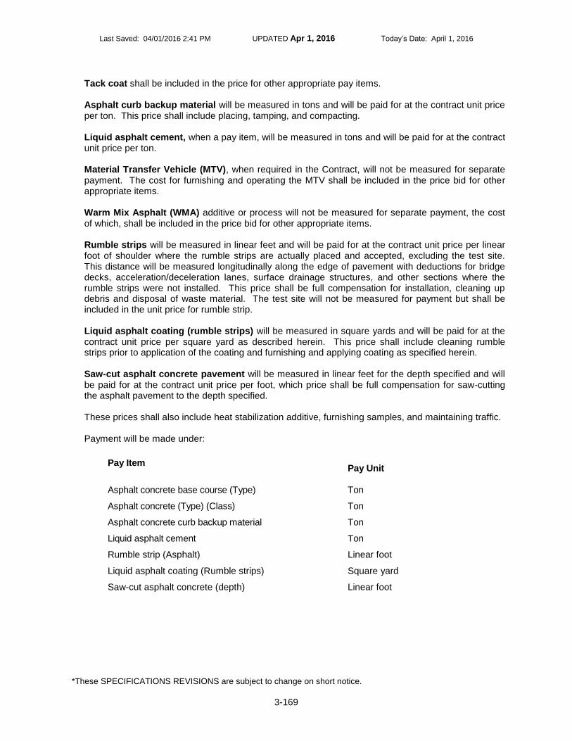
Last Saved: 04/01/2016 2:41 PM UPDATED Apr 1, 2016 Today’s Date: April 1, 2016
*These SPECIFICATIONS REVISIONS are subject to change on short notice.
3-169
Tack coat shall be included in the price for other appropriate pay items. Asphalt curb backup material will be measured in tons and will be paid for at the contract unit price per ton. This price shall include placing, tamping, and compacting. Liquid asphalt cement, when a pay item, will be measured in tons and will be paid for at the contract unit price per ton. Material Transfer Vehicle (MTV), when required in the Contract, will not be measured for separate payment. The cost for furnishing and operating the MTV shall be included in the price bid for other appropriate items. Warm Mix Asphalt (WMA) additive or process will not be measured for separate payment, the cost of which, shall be included in the price bid for other appropriate items. Rumble strips will be measured in linear feet and will be paid for at the contract unit price per linear foot of shoulder where the rumble strips are actually placed and accepted, excluding the test site. This distance will be measured longitudinally along the edge of pavement with deductions for bridge decks, acceleration/deceleration lanes, surface drainage structures, and other sections where the rumble strips were not installed. This price shall be full compensation for installation, cleaning up debris and disposal of waste material. The test site will not be measured for payment but shall be included in the unit price for rumble strip. Liquid asphalt coating (rumble strips) will be measured in square yards and will be paid for at the contract unit price per square yard as described herein. This price shall include cleaning rumble strips prior to application of the coating and furnishing and applying coating as specified herein. Saw-cut asphalt concrete pavement will be measured in linear feet for the depth specified and will be paid for at the contract unit price per foot, which price shall be full compensation for saw-cutting the asphalt pavement to the depth specified. These prices shall also include heat stabilization additive, furnishing samples, and maintaining traffic. Payment will be made under:
Pay Item
Pay Unit
Asphalt concrete base course (Type) Ton
Asphalt concrete (Type) (Class) Ton
Asphalt concrete curb backup material Ton
Liquid asphalt cement Ton
Rumble strip (Asphalt) Linear foot
Liquid asphalt coating (Rumble strips) Square yard
Saw-cut asphalt concrete (depth) Linear foot
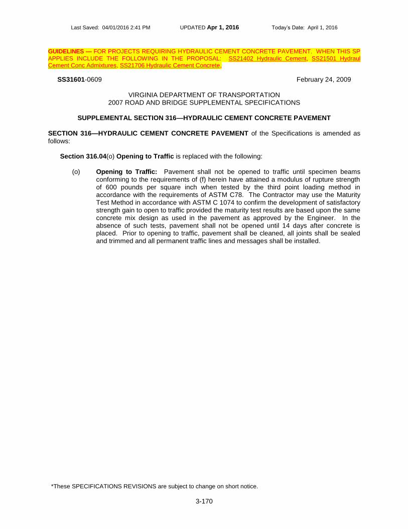
Last Saved: 04/01/2016 2:41 PM UPDATED Apr 1, 2016 Today’s Date: April 1, 2016
*These SPECIFICATIONS REVISIONS are subject to change on short notice.
3-170
GUIDELINES — FOR PROJECTS REQUIRING HYDRAULIC CEMENT CONCRETE PAVEMENT. WHEN THIS SP
APPLIES INCLUDE THE FOLLOWING IN THE PROPOSAL: SS21402 Hydraulic Cement, SS21501 Hydraul Cement Conc Admixtures, SS21706 Hydraulic Cement Concrete,
SS31601-0609 February 24, 2009
VIRGINIA DEPARTMENT OF TRANSPORTATION 2007 ROAD AND BRIDGE SUPPLEMENTAL SPECIFICATIONS
SUPPLEMENTAL SECTION 316—HYDRAULIC CEMENT CONCRETE PAVEMENT
SECTION 316—HYDRAULIC CEMENT CONCRETE PAVEMENT of the Specifications is amended as follows:
Section 316.04(o) Opening to Traffic is replaced with the following:
(o) Opening to Traffic: Pavement shall not be opened to traffic until specimen beams conforming to the requirements of (f) herein have attained a modulus of rupture strength of 600 pounds per square inch when tested by the third point loading method in accordance with the requirements of ASTM C78. The Contractor may use the Maturity Test Method in accordance with ASTM C 1074 to confirm the development of satisfactory strength gain to open to traffic provided the maturity test results are based upon the same concrete mix design as used in the pavement as approved by the Engineer. In the absence of such tests, pavement shall not be opened until 14 days after concrete is placed. Prior to opening to traffic, pavement shall be cleaned, all joints shall be sealed and trimmed and all permanent traffic lines and messages shall be installed.

Last Saved: 04/01/2016 2:41 PM UPDATED Apr 1, 2016 Today’s Date: April 1, 2016
*These SPECIFICATIONS REVISIONS are subject to change on short notice.
3-171
GUIDELINES — PROJECTS REQUIRING STONE MATRIX ASPHALT CONCRETE PAVEMENT. WHEN THIS
PROVISION APPLIES INCLUDE THE FOLLOWING IN THE PROPOSAL SS21113 SuperPave -Asphalt Concrete and SS31510 SuperPave -Asphalt Conc Place, SS24807 SMA -Asphalt Concrete
SS31706-1214 December 2, 2014
VIRGINIA DEPARTMENT OF TRANSPORTATION 2007 ROAD AND BRIDGE SUPPLEMENTAL SPECIFICATIONS
SUPPLEMENTAL SECTION 317—STONE MATRIX ASPHALT CONCRETE PLACEMENT
SECTION 317—STONE MATRIX ASPHALT CONCRETE PAVEMENT of the Specifications is replaced with the following:
317.01—Description This specification covers the furnishing, installation, and acceptance criteria for constructing stone matrix asphalt (SMA) concrete pavement. SMA shall be in accordance with these specifications and Section 315. 317.02—Materials
(a) Coarse aggregate shall conform to the requirements of Section 248.02(a). (b) Fine aggregate shall conform to the requirements of Section 248.02(b). (c) Asphalt binder shall conform to the requirements of Section 248.02(c). (d) Mineral filler shall conform to the requirements of Section 248.02(d). (e) Fiber additive shall conform to the requirements of Section 248.02(e).
317.03—Composition of SMA Mixture Composition of Stone Matrix Asphalt shall conform to the requirements of Section 248. 317.04—Acceptance Acceptance of Stone Matrix Asphalt shall conform to the requirements of Section 248. 317.05—SMA Mixing Plant
(a) Mineral filler handling shall be in accordance with the requirements of Section
248.05(a). (b) Fiber addition shall be in accordance with the requirements of Section 248.05(b). (c) Hot-mixture storage shall conform to the requirements of Section 248.05(c). (d) Mixing temperatures shall conform to the requirements of Section 248.05(d).

Last Saved: 04/01/2016 2:41 PM UPDATED Apr 1, 2016 Today’s Date: April 1, 2016
*These SPECIFICATIONS REVISIONS are subject to change on short notice.
3-172
317.06—Weather Restrictions SMA mixture shall be placed only when the ambient and surface temperatures are 50 degrees F or above, unless a warm mix additive or process approved by the Department is used to produce the SMA at which the surface temperature must be 40 degrees F or above. 317.07—Placing and Finishing For mixtures containing PG 64H-22 asphalt binder, the mixture temperature shall not be less than 300 degrees F in the truck and less than 290 degrees F
immediately behind the screed.
For mixtures containing PG 64E-22 asphalt binder, the mixture temperature in the truck and immediately behind the screed shall not be less than the minimum compaction temperature provided by the liquid asphalt supplier. The minimum mixture or compaction temperature immediately behind the screed when a warm mix asphalt additive or process is used to produce the SMA shall not be less than 200
oF.
The Contractor shall be responsible for a continuous paving operation that provides for maintaining constant steady movement of the paver. In the event that stop and go of the paver occurs to the extent that screed settlement, thermal segregation, mechanical segregation, or any other visibly deleterious impacts to the mat are being observed, the Engineer will stop production and laydown of the mixture until the Contractor has made satisfactory changes in the production, hauling, and placement operations resulting in a constant steady movement of the paver. The Contractor shall employ a Material Transfer Vehicle (MTV) during the placement of SMA mixes. The Contractor’s paving operation shall have remixing capability in either the MTV or a paver-mounted hopper to produce a uniform, nonsegregated mix with uniform temperature. The MTV and paver combination shall have a minimum storage capacity of 15 tons. In the event of an equipment break down of the paving train, paving shall be discontinued once the material on-site has been placed and no more material shall be shipped from the hot-mix plant. 317.08—Compaction Immediately after the mixture has been spread and struck off, it shall be thoroughly and uniformly compacted by rolling. Rolling shall be accomplished with steel wheel roller(s) with a minimum weight of 10 tons. A minimum of three rollers shall be available at all times for compaction and/or finish rolling. The Contractor shall approach the use of vibratory rollers on SMA with caution to minimize coarse aggregate fracture/breakage in the aggregate skeleton of SMA mixes. If the Contractor elects to use a vibratory roller, the mat should not receive more than three vibratory passes. The Contractor shall use the roller on only the highest frequency and lowest amplitude setting. It shall be the Contractor’s responsibility to adjust the rolling procedures to provide the specified pavement density. Rollers shall move at a uniform speed. Rolling shall be continued until all roller marks are eliminated and the minimum density has been obtained. The Contractor shall monitor density during the compaction process by use of nuclear density gages to ensure that the minimum required compaction is being obtained. During the trial section, the Department will randomly select 3 plug or core locations to determine the in-place density in accordance to VTM-22.

Last Saved: 04/01/2016 2:41 PM UPDATED Apr 1, 2016 Today’s Date: April 1, 2016
*These SPECIFICATIONS REVISIONS are subject to change on short notice.
3-173
The Contractor shall keep the wheels of the rollers properly moistened with water that has been mixed with very small quantities of detergent or other approved additives to prevent adhesion of the mixture to the rollers. For the purposes of evaluating and determining acceptance, each day’s production shall be considered a lot unless the paving length is less than 3,000 linear feet or greater than 7,500 linear feet. When paving is less than 3,000 feet, it shall be combined with the previous day’s production or added to the next day’s production to create a lot as described below. The standard size of a lot shall be 5,000 linear feet, with 1,000 foot sublots, of any pass 6 feet or greater made by the paving train for the thickness of the course. With the Engineer’s approval the lot size may be increased to 7,500 linear foot lots with 1,500 foot sublots when the normal daily production is in excess of 7,000 feet. Pavers traveling in echelon will be considered as two passes. When a partial lot occurs at the end of a day’s production or upon completion of the project, the lot size shall be redefined as follows:
● If the partial lot contains one or two sublots, the sublots will be added to the previous lot. ● If the partial lot contains three or four sublots, the partial lot will be redefined to be an
entire lot. The Contractor shall perform acceptance testing for density for each sublot by obtaining one sawed 4 inch by 4 inch specimen, or one 4-inch-diameter cores, at a single random test site specified by the Engineer. Test sites shall not be located within 12 inches of the edge of any application width for surface and intermediate mixes.
● The sub-lot site shall be marked as described in VTM-76. ● The bulk specific gravity of the cores shall be determined in accordance with VTM-6. ● The density of the cores shall be determined in accordance with the requirements of
VTM-22. Cores or plugs shall be bulked in the presence of the Department. The Department reserves the right to have the cores or plugs bulked on the project site. Sublot test sites shall be numbered sequentially per lot, marked on the pavement, filled with the paving mixture, and compacted prior to completion of each day’sproduction. The payment for lot density will be in accordance with the following schedule:
Payment Schedule
% Density Achieved % of Payment
More than 98.0 97
94.0 to 98.0 100
92.0 to 93.9 85
90.0 to 91.9 65
Less than 90.0 Remove and replace
317.09—Trial Section

Last Saved: 04/01/2016 2:41 PM UPDATED Apr 1, 2016 Today’s Date: April 1, 2016
*These SPECIFICATIONS REVISIONS are subject to change on short notice.
3-174
The Engineer will require the Contractor to construct a trial section(s) for evaluation at least 1 week but not more than 30 days prior to the start of production of a SMA mix not placed the previous year on a state roadway. The trial section shall be a maximum of 300 tons, and shall be constructed at a site designated in the contract or proposed by the contractor and approved by the Engineer. The Department will use the trial section to evaluate the mixing plant process control, mixture draindown characteristics, placement procedures, SMA surface appearance, and compaction patterns and to calibrate the nuclear density device. In addition, the percentage of flat and elongated particles will be calculated on the SMA material produced for the trial section in accordance with the requirements of VTM-121 and compared to the maximum limits specified in the Coarse Aggregate Table in Section 248.02(a). The Engineer will require a passing flat and elongated sample for acceptance of the trial section. During the trial section(s), the Engineer will randomly select 3 plugs or core locations to determine the in-place density in accordance with VTM-22. Payment for density will be in accordance with the Payment Schedule listed in Sec. 317.08. The Contractor shall remove and replace failing trial sections based on the following criteria. The Engineer will deem a trial section to have failed if the VTM is less than 1.0 percent or exceeds 5.0 percent; if the VCA of the mix exceeds the VCA of the dry rodded condition; if the field density is less than 90.0 percent of the maximum theoretical density; or if excessive flushing/bleeding occurs in the wheel paths. Payment for, and limitations on, the trial section shall be as stipulated in Section 317.11. The Contractor shall be responsible for the cost for removing any failed trial section. 317.10—Prepaving Conference The Department will hold a prepaving conference with the Contractor prior to the start of production for those contractors who have never produced or placed Stone Matrix Asphalt. 317.11—Measurement and Payment Stone matrix asphalt will be measured in tons and will be paid for at the contract unit price per ton for the mix type specified, which price shall include all materials, additives, and equipment as described herein. The initial trial section will be paid for at the contract unit price for the mix type specified. Up to one additional trial section of the mix type specified will be paid for at the contract unit price. If additional trial sections are needed, the Department and the Contractor shall negotiate the price based upon a reduced percentage of the contract unit price. The Department will pay for no more than four trial sections. The Contractor shall be fully responsible for any additional test sections required to produce and install an acceptable mixture at the Contractor’s expense.
Payment will be made under:
Pay Item
Pay Unit
Stone matrix asphalt, (Type) (Class) Ton

Last Saved: 04/01/2016 2:41 PM UPDATED Apr 1, 2016 Today’s Date: April 1, 2016
*These SPECIFICATIONS REVISIONS are subject to change on short notice.
3-175
———— CNSP SELECT USE 300 SERIES SPCNs and SPs ————
The following are Select Use Special Provisions. None have been through the Department’s complete Specifications Committee review/comment/acceptance process and are not part of the Standard Specifications. They are to be considered as project-specific and may be subject to modifications required to meet specific project conditions or requirements for Federal funding. Anyone making modifications is responsible for obtaining the appropriate expertise in the discipline applicable to the modification. If modifications are made the date must also be changed to reflect the current date. Please send a copy of the modified special provision with the new date and specific project number to [email protected] so it may be added to the Specifications Stockpile.

Last Saved: 04/01/2016 2:41 PM UPDATED Apr 1, 2016 Today’s Date: April 1, 2016
*These SPECIFICATIONS REVISIONS are subject to change on short notice.
3-176
cu312000a Vacuuming Emul Asp Slurry Seal GUIDELINES – FOR RICHMOND DISTRICT PROJECTS WITH EMULSIFIED ASPHALT SLURRY SEAL.
VACUUMING EMULSIFIED ASPHALT SLURRY SEALS
The Special Provision for EMULSIFIED ASPHALT SLURRY SEAL (S312DM2-1112) is amended as follows:
Section IV. C. Application is amended to include the following as the third paragraph:
All routes receiving an Emulsified Asphalt Slurry Seal or a Cape Seal (Modified Single Seal or Modified Double Seal with Slurry Seal) shall be lightly broomed to remove loose aggregate prior to opening the pavement surface to traffic. All excess aggregate material on the pavement surface travel lane(s) and accumulated along curb and gutter sections, the edge of pavement/lawns, and hard-surfaced driveway entrances shall be removed by mobile vacuum unit after either final or interim riding surface has been opened to traffic as directed by the Engineer up to three weeks after pavement surface has been opened to traffic.
9-4-14a (SPCN) cu312001a Cape Seal Treatment GUIDELINES – USE WHEN REQUESTED BY THE DESIGNER. INCLUDE S314CM3 Asphalt Surface Treatment, S312DM2
Emulsified Asphalt Slurry Seal, S512L10 Maintaining Traffic -Sched, and S704M06 Pavement Markings and Markers.
CAPE SEAL TREATMENT — This work shall consist of furnishing and applying asphalt surface treatment to the existing roadway surface, allowing sufficient time for curing followed by cleanup, then furnishing and applying emulsified asphalt slurry seal as the finished surface. The sequence of work shall be as follows:
1. The existing asphalt surface shall be patched at locations in accordance with the provisions of
this contract and as directed by the Engineer. 2. All pavement markings shall be eradicated in accordance with the special provision for SECTION
512—MAINTAINING TRAFFIC (ASPHALT SCHEDULES). 3. Asphalt surface treatment shall be applied in accordance with the special provision for ASPHALT
SURFACE TREATMENT. Asphalt surface treatment shall be a modified single seal or modified double seal with liquid asphalt material of CRS-2L emulsified asphalt, aggregate size No. 8P, and blot coat of No. 9 aggregate.
4. Temporary pavement markings shall be installed and maintained in accordance with the special
provision for SECTION 704—PAVEMENT MARKINGS AND MARKERS. 5. Asphalt surface treatment shall be allowed to cure for two weeks after application. 6. After curing, excess and loose material resulting from the vehicular traffic that occurred during the
asphalt surface treatment curing period shall be removed from the roadway.
Last Saved: 04/01/2016 2:41 PM UPDATED Apr 1, 2016 Today’s Date: April 1, 2016
*These SPECIFICATIONS REVISIONS are subject to change on short notice.
3-177
7. Emulsified asphalt slurry seal shall be applied in accordance with the special provision for EMULSIFIED ASPHALT SLURRY SEAL. Emulsified asphalt slurry seal shall be Type B or C applied at a rate of 20 pounds per square yard.
8. Temporary and permanent pavement markings shall be installed in accordance with the special
provision for SECTION 704—PAVEMENT MARKINGS AND MARKERS.
Cape seal treatment will be measured and paid for in accordance with the appropriate asphalt surface treatment and emulsified asphalt slurry seal pay items and pay units specified in the Contract to complete the work. 10-21-14a (SPCN)
cu314000a Vacuuming Asp Sur Treat GUIDELINES – FOR RICHMOND DISTRICT PROJECTS WITH ASPHALT SURFACE TREATMENT.
VACUUMING ASPHALT SURFACE TREATMENTS
The Special Provision for ASPHALT SURFACE TREATMENT (S314CM3-1012) is amended as follows:
Section IV. (b) Modified Single Seal and Modified Double Seal Treatments is amended to include the following as the third paragraph:
All routes receiving an Asphalt Surface Treatment (Modified Single Seal or Modified Double Seal) shall be lightly broomed to remove loose aggregate prior to opening the pavement surface to traffic. All excess aggregate material on the pavement surface travel lane(s), and accumulated along curb and gutter sections, the edge of pavement/lawns, and hard-surfaced driveway entrances shall be removed by mobile vacuum unit after surface treatment has been exposed to traffic as directed by the Engineer up to three weeks after final treatment has been opened to traffic.
Section VI. - Measurement and Payment is amended to include the following:
Vacuuming shall be included in the price of other appropriate items. 9-4-14a (SPCN) cu315000a Thin Hot Mix (THMACO) Rideability GUIDELINES – ASPHALT PROJECTS WHERE “THIN HOT MIX ASPHALT CONCRETE OVERLAY” IS USED AND “RIDEABILITY” APPLIES (PLANT MIX ONLY).
SECTION 315—ASPHALT CONCRETE PAVEMENT - The Special Provision for Rideability is amended to include the following:
This project will be subject to the Special Provision for RIDEABILITY except that Rideability will not be waived as a result of AC layer thickness and the THIN HOT MIX ASPHALT CONCRETE OVERLAY will not be considered a “scratch course.”

Last Saved: 04/01/2016 2:41 PM UPDATED Apr 1, 2016 Today’s Date: April 1, 2016
*These SPECIFICATIONS REVISIONS are subject to change on short notice.
3-178
1-25-10a (SPCN)

Last Saved: 04/01/2016 2:41 PM UPDATED Apr 1, 2016 Today’s Date: April 1, 2016
*These SPECIFICATIONS REVISIONS are subject to change on short notice.
3-179
SU302001D Pipe Rehabilitation GUIDELINES – PROJECTS REQUIRING PIPE REHABILITATION.
VIRGINIA DEPARTMENT OF TRANSPORTATION SPECIAL PROVISION FOR
PIPE REHABILITATION
July 30, 2015 I. DESCRIPTION
This work shall consist of the rehabilitation of existing storm water, surface water pipe culverts and/or sanitary sewer lines by the method or methods specified at the designated locations described in the Contract using various standard and non-standard methodologies/technologies in accordance with the requirements of this provision and as directed by the Engineer.
II. MATERIALS Cement grout shall conform to Section 218.03(b) or (d) of the Specifications. Corrugated steel pipe liner used for Method C rehabilitation shall conform to Section 232.02 of the Specifications and shall be 10 gage with 3-inch by 1-inch angular corrugations. Corrugated steel pipe used as liners shall be manufactured by QC/QA producers on the VDOT Materials Division Approved Products List. Flexible pipe liner systems used for Method D rehabilitation shall be from the VDOT Materials Division Approved Products List 38 and may be subject to limitations for use as specified herein, by site-specific limitations for those locations listed in the Contract, or as shown on the VDOT Materials Division Approved Products List 38 for the specific liner system. Where such is the case, the Contractor shall use only that type or those types that conform to the requirements for all pipe rehabilitation systems listed in List 38 and what the Department has specified for the specific location listed in the bid proposal documents. The Contractor shall furnish information, services, or other requirements as detailed on List 38 for all materials used for pipe rehabilitation system(s) specified in the Contract. Flexible pipe liners shall be one or more of the following categories as designated in the Contract:
● Category A - Cured-In-Place Pipe (CIPP)
● Category B - Fold and Form flexible liners
● Category C – High Density Polyethylene (HDPE), Polyvinylchloride (PVC), or Polypropylene (PP) slip liners
● Category D - Spray-On liners When Category A - Cured-In-Place Pipe liners are specified, the liner system supplied by the Contractor shall conform to the following requirements as supported by submitted design calculations:
● Must meet Drainage Manual, Chapter 8, Section 8.3.6.7 - Table A, Flexible Liner (Method D) Type Selection Guidelines for Category A systems.

Last Saved: 04/01/2016 2:41 PM UPDATED Apr 1, 2016 Today’s Date: April 1, 2016
*These SPECIFICATIONS REVISIONS are subject to change on short notice.
3-180
● Must exactly follow ASTM F1216 Appendix X1.2.2 Fully Deteriorated Gravity Pipe Conditions.
● Provide groundwater table elevation at crown of pipe.
● Traffic loading is HL-93, ignore after 8 ft of cover except for multiple barrel rehabs, continue indefinitely.
● Total wet unit weight of soil is 120 pcf, 135 pcf saturated.
● Modulus of soil reaction (based on VDOT pipe installation standards):
● 0-5 ft of cover = 1.8 ksi
● >5-10 ft of cover = 2 ksi
● >10-30 ft of cover = 2.2 ksi
● >30-60 ft of cover = 2.6 ksi
● >60 ft of cover = 2.8 ksi
● Factor of safety N = 2.0.
● Construction:
● Any voids around exterior of host pipe must be filled for design assumptions to be valid.
● Shall specify the following:
● Method for installation and curing.
● Individual components.
● Tube type (whether reinforced or non-reinforced).
● Manufacturer name and type of resin including catalyst.
● Volume of resin required to achieve proper impregnation and curing.
● Shall include lot numbers and expiration dates of all supplied components.
● Shall have an impermeable inner and outer plastic film or plastic pre-liner to promote complete polymerization, prevent resin migration and loss, and prevent contamination of the interior of the finished product.
● Shall conform to the following table:
Property Test Procedures Physical Requirements
Tensile strength at yield ASTM D-638 3,000 PSI
Modulus of elasticity ASTM D-790 200,000 PSI
Flexural strength ASTM D-790 4,000 PSI
When Category B Fold and Form flexible liners are specified, the liner system supplied by the Contractor shall conform to the following requirements as supported by submitted design calculations:

Last Saved: 04/01/2016 2:41 PM UPDATED Apr 1, 2016 Today’s Date: April 1, 2016
*These SPECIFICATIONS REVISIONS are subject to change on short notice.
3-181
● Must meet Drainage Manual, Chapter 8, Section 8.3.6.7 - Table A, Flexible Liner
(Method D) Type Selection Guidelines for Category B systems. ● Must exactly follow ASTM F1947 Appendix X1.2.2 Fully Deteriorated Design
Condition or ASTM F1867 Appendix X1.2.3 Fully Deteriorated Design Condition.
● Provide groundwater table elevation at crown of pipe. ● Traffic loading is HL-93, ignore after 8 ft of cover except for multiple barrel
rehabs, continue indefinitely.
● Total wet unit weight of soil is 120 pcf, 135 pcf saturated.
● Modulus of soil reaction (based on VDOT pipe installation standards):
● 0-5 ft of cover = 1.8 ksi
● >5-10 ft of cover = 2 ksi
● >10-30 ft of cover = 2.2 ksi
● >30-60 ft of cover = 2.6 ksi
● >60 ft of cover = 2.8 ksi
● Factor of safety N = 2.0.
● Construction:
● Any voids around exterior of host pipe must be filled for design assumptions to be valid.
When Category C HDPE, PVC, PP slip liners or spirally wound liners are specified, the liner system supplied by the Contractor shall conform to the following requirements as supported by submitted design calculations:
● Must meet Drainage Manual, Chapter 8, Section 8.3.6.7 - Table A, Flexible Liner (Method D) Type Selection Guidelines for Category C systems.
● Must follow AASHTO LRFD Bridge Design Specifications, Section 12, version in use by VDOT Structure & Bridge Division at time of submittal, except that PVC spirally wound liners will follow ASTM F1697 and F1741.
● Must provide SDR and outside diameter of pipe, for solid wall pipe. ● Must provide outside diameter, inside diameter, diameter to centroid of wall,
moment of inertia, gross and effective areas of wall, for corrugated or profile wall pipe.
● Provide groundwater elevation at crown of pipe.
● Traffic loading is HL-93, ignored after 8 ft of cover except for multiple barrel rehabs continue indefinitely.
● Total wet unit weight of soil is 120 pcf, 135 pcf saturated.
● Constrained soil modulus (based on VDOT pipe installation standards):

Last Saved: 04/01/2016 2:41 PM UPDATED Apr 1, 2016 Today’s Date: April 1, 2016
*These SPECIFICATIONS REVISIONS are subject to change on short notice.
3-182
● 0-5 ft of cover = 1.8 ksi
● >5-10 ft of cover = 2 ksi
● >10-30 ft of cover = 2.2 ksi
● >30-60 ft of cover = 2.6 ksi
● >60 ft of cover = 2.8 ksi
● Shape factor shall be 3.0.
● Long term modulus shall be used for stiffness computation.
● Live Load Distribution Factor = 1.
● Deflection Lag Factor = 1.5.
● Bedding Factor = 0.1.
● Installation Factor = 1.5.
● Maximum deflection, deflection needed in any computations, and service long-term tension strain limit shall be 5 percent for PE, and either 5 percent or 3.5 percent for PVC depending on cell class as per AASHTO LRFD Bridge Design Specs Table 12.12.3.3.1, and 3.5 percent for PP.
● Poisson’s ratio of soil shall be 0.3.
● Earth load modifier shall be 1.05 and live load modifier shall be 1.0.
● Manning’s N number for open channel flow n = 0.011 for smooth interior PVC and 0.012 for smooth interior HDPE and PP. (For hydraulic design.)
● Construction:
● Any voids around exterior of host pipe must be filled for design assumptions to be valid.
● The annular space between host pipe and liner pipe must be fully grouted for design assumptions to be valid.
When Category D Spray-on liners are specified for structural rehabilitation, the liner system supplied by the Contractor shall conform to the following requirements as supported by submitted design calculations:
● Must meet Drainage Manual, Chapter 8, Section 8.3.6.7 - Table A, Flexible Liner (Method D) Type Selection Guidelines for Category D systems.
● Because of the variety of spray-on liners available, several design options may
be used. For cementitous liners, design shall be guided similarly to nonreinforced concrete pipe, or alternately, similar to fiberglass pipe (high modulus material). For other liners, polyurea for example, design shall be guided similarly to fiberglass pipe (high modulus material) or simply as plastic pipe if flexural modulus or ring bending strain results are not satisfactory.
● Cementitious liner treated similarly as fiberglass pipe (this method is based
on the proposed AASHTO LRFD Bridge Design Specifications for fiberglass pipe):
Last Saved: 04/01/2016 2:41 PM UPDATED Apr 1, 2016 Today’s Date: April 1, 2016
*These SPECIFICATIONS REVISIONS are subject to change on short notice.
3-183
● Articles referenced below are from AASHTO LRFD Bridge Design Specifications, Section 12, version in use by VDOT Structure & Bridge Division at time of submittal.
● The flexibility factor for fiberglass pipe shall be determined in accordance
with Article 12.12.3.6, but with the modulus replaced by flexural modulus, and the flexibility factor shall be limited as specified in Article 12.5.6.3.
● Follow Section 12.12.2.2 for deflection, except replace modulus with flexural modulus (ksi) and drop the “escD” term.
● Factored long term strain due to flexure shall be less than or equal to
0.9*Sb (Sb is ring bending strain). ● Factored buckling strain demand shall be less than or equal to
0.7*nominal strain capacity for buckling demand, computed per Eqn. 12.12.3.10.1e-2, except replace modulus with flexural modulus and soil resistance factor shall be 1.0. Factored buckling strain shall be:
● [[13.65 *Height of soil over crown (in feet) + 1.75*PL] * radius of liner to centroid of wall in in.]/(flexural modulus in ksi * X-S area of liner in in
2/in), where PL is determined from Eqn. 12.12.3.9-1.
● Flexural modulus shall be determined from pipe stiffness tests and
per Appendix 2 of ASTM D2412, and shall be at least 1,200 ksi. ● Long term ring bending strain, Sb, shall be determined in accordance
with ASTM D5365 and results extrapolated to both 50 years and 75 years, and shall be at least 0.006.
● It is recognized that for a spray-on product, obtaining specimens for flexural modulus and ring bending strain tests would require special formwork at a fabrication facility. Similarly as is done for watertight joint testing, these tests may be done and witnessed by a PE and a report submitted, which may then be used as proof of results without having to perform the tests for each future project, as long as materials and processes have not changed. Application thicknesses not tested may be interpolated by a satisfactory method. Extrapolation beyond thicknesses tested will not be permitted on the thin side, and will only be permitted for thicker applications by satisfactory statistical data.
● GW table at crown of pipe. ● Traffic loading is HL-93, ignored after 8 ft of cover except for multiple
barrel rehabs continue indefinitely.
● Unit weight of soil is 120 pcf, 135 pcf saturated.
● Modulus of soil reaction (based on VDOT pipe installation standards):
● 0-5 ft of cover = 1.8 ksi ● >5-10 ft of cover = 2 ksi
● >10-30 ft of cover = 2.2 ksi

Last Saved: 04/01/2016 2:41 PM UPDATED Apr 1, 2016 Today’s Date: April 1, 2016
*These SPECIFICATIONS REVISIONS are subject to change on short notice.
3-184
● >30-60 ft of cover = 2.6 ksi
● >60 ft of cover = 2.8 ksi
● Shape factor shall be 3.0.
● Live Load Distribution Factor = 1.
● Deflection Lag Factor = 1.5.
● Bedding Factor = 0.1.
● Installation Factor = 1.5.
● Maximum deflection and deflections needed in any computations shall be 5 percent.
● Poisson’s ratio of soil shall be 0.3.
● Earth load modifier shall be 1.05 and live load modifier shall be 1.0.
● Other liner types treated similarly as fiberglass pipe: ● Same as for cementitous liner treated similarly as fiberglass pipe
above.
● Other liner types treated same as plastic pipe: ● Follow AASHTO LRFD Bridge Design Specifications, Section 12, for
thermoplastic pipe, version in use by VDOT Structure & Bridge Division at time of submittal.
● GW table at crown of pipe. ● Traffic loading is HL-93, ignored after 8 ft of cover except for multiple
barrel rehabs continue indefinitely.
● Unit weight of soil is 120 pcf, 135 pcf saturated.
● Modulus of soil reaction (based on VDOT pipe installation standards):
● 0-5 ft of cover = 1.8 ksi ● >5-10 ft of cover = 2 ksi
● >10-30 ft of cover = 2.2 ksi
● >30-60 ft of cover = 2.6 ksi
● >60 ft of cover = 2.8 ksi
● Shape factor shall be 3.0.
● Live Load Distribution Factor = 1.
● Deflection Lag Factor = 1.5.
● Bedding Factor = 0.1.

Last Saved: 04/01/2016 2:41 PM UPDATED Apr 1, 2016 Today’s Date: April 1, 2016
*These SPECIFICATIONS REVISIONS are subject to change on short notice.
3-185
● Installation Factor = 1.5.
● Maximum deflection and deflections needed in any computations shall be 5 percent.
● Poisson’s ratio of soil shall be 0.3.
● Earth load modifier shall be 1.05 and live load modifier shall be 1.0.
● Construction:
● Any voids around exterior of host pipe must be filled for design assumptions to be valid.
Smooth-wall steel pipe liner used for Method E rehabilitation shall conform to Section 232.02(c)5 of the Specifications.
III. GENERAL PROCEDURES The Contractor shall submit site specific working drawings (and supportive calculations) to the Engineer according to the requirements herein and Section 105.10 of the Specifications for the rehabilitation method selected by the Contractor from the allowable methods per each location listed in the Contract prior to the start of pipe rehabilitation operations. The Contractor shall furnish to the Engineer a certification of the acceptability of the proposed rehabilitation system to provide the necessary hydraulic capacity and structural strength to support the anticipated total load and hydrology at the site of rehabilitation, as determined from a review that has been signed and sealed by a Professional Engineer holding a valid license to practice engineering in the Commonwealth of Virginia. Such certification shall cover all design data, supporting calculations and planned rehabilitation materials. All work and equipment shall be contained within the existing right-of-way. In the event a temporary construction easement is deemed necessary due to the selected method or product chosen by the Contractor, the Contractor shall obtain such additional easement for his convenience at no additional cost to the Department. The Contractor shall maintain all lanes of traffic at all times in accordance with the Special Provision for Section 512—Maintaining Traffic – Non-Schedules (Lump Sum) unless otherwise directed by the Engineer. This maintenance of traffic shall include temporary detours if required by the Contractor’s method of operations to facilitate construction and where permitted by the locality and the Department. When temporary detours are required, the Contractor shall design and construct temporary detours in accordance with Sections 105.14 and 512 of the Specifications and Standard GS-10 of the Road and Bridge Standards respectively. The cost for maintenance of traffic including temporary detours shall be bid as a lump sum amount for the specific location of each pipe rehabilitation as shown in the Contract in accordance with the Special Provision for Section 512—Maintaining Traffic – Non-Schedules (Lump Sum) unless otherwise specified in the Contract. The Contractor shall contact Miss Utility prior to commencing any work that may conflict with existing utilities, and shall coordinate with the utility company(ies) and the Engineer for any adjustments deemed necessary to complete the work. The Contractor shall notify the VDOT Area Construction Engineer at least 48 hours prior to initiation of rehabilitation operations at the site.

Last Saved: 04/01/2016 2:41 PM UPDATED Apr 1, 2016 Today’s Date: April 1, 2016
*These SPECIFICATIONS REVISIONS are subject to change on short notice.
3-186
In the event the selected method of rehabilitation requires disturbing existing surfaces, these surfaces shall be restored in kind to original pre-construction conditions after rehabilitation operations have been completed and the cost thereof shall be included in the price bid for Pipe Rehabilitation for the specified location. The Contractor shall obtain all required OSHA confined space entry permits where these are required by the Contractor’s operations and the scope of work in the Contract. The Department has performed an inspection of the existing pipes in each location listed in the Contract to determine the extent and nature of each pipe’s deterioration or damage so as to designate the allowable methods of rehabilitation of the pipe at that specific site. Using the information collected from this inspection, the Department has determined through its engineering analysis the best practical method(s) of rehabilitation for each respective site (location) taking into account site specific conditions such as installation working space for the various types of liners, hydraulic capacity before and after rehabilitation, height of cover, soil density, and loading conditions, among other criteria. The Contractor shall select from the allowable method(s)/category(ies) for each specified location or site indicated in the Contract, how the Contractor chooses to perform the work. Regardless of the final method selected, the Contractor shall provide the Engineer documentation of the proposed procedures, materials, equipment, incidentals and resources the Contractor shall use to ensure successful rehabilitation of the existing pipe(s) to assist the Engineer in monitoring the Contractor’s operations. The Contractor will not be permitted to substitute a different method(s) and category(ies), if designated, than that or those specified for the location described in the Contract. The Contractor shall clear the existing pipe(s) designated for rehabilitation of any debris, protrusions greater than ½ inch in height and any other potential obstructions prior to the start of rehabilitation efforts. The Contractor shall then thoroughly clean and prepare the host pipe prior to the liner installation. Cleaning shall conform to the recommendations of the liner manufacturer/producer or supplier of the methodology to be used. In the absence of such recommendations, the Contractor shall submit his/her proposed method for cleaning and preparing the host pipe for the Engineer’s review and acceptance. A copy of the cleaning methodology and materials shall be provided to the Engineer at least 2 working days prior to beginning the work at that location. Please note: All specified time limits in these specifications refer to working days, not calendar days. Pre-Installation Inspection – In addition to the inspection performed by the Department, and not later than 2 to 3 weeks after cleaning the host pipe at the specified location, the Contractor shall perform a pre-installation visual/video inspection at the designated location of the pipe shown in the Contract or where directed by the Engineer. This visual/video inspection shall be conducted in accordance with the requirements of this specification and VTM 123 to verify pre-construction conditions. The inspection shall be performed in the presence of the Engineer. Video inspections shall be clearly labeled on the media with the time, date, and location of the pipe inspected. A copy of the video inspection shall be furnished to the Engineer prior to the start of rehabilitative construction. The cost of pre-Installation Inspection will be considered incidental to the cost of the installation. In the event the Contractor’s inspection shows the method of rehabilitation the Contractor has selected is no longer viable at that location as verified by the Engineer, the Contractor shall select another allowable method, if specified, from those designated in the Contract. If no other method is designated, or if other methods of rehabilitation also now are deemed impracticable at that location, further work will be determined in accordance with Section 104.03. The following methods of pipe rehabilitation are approved by the Department; however, not all methods may be appropriate for each individual location. The Contractor shall consult the Contract to determine the method (and category if designated) or methods (and categories if designated) that are permitted per the location cited. Individual methods shall conform to the criteria specified.

Last Saved: 04/01/2016 2:41 PM UPDATED Apr 1, 2016 Today’s Date: April 1, 2016
*These SPECIFICATIONS REVISIONS are subject to change on short notice.
3-187
PIPE REHABILITATION BY LINER Method C - Corrugated steel pipe liner shall be rehabilitation by insertion of a rigid corrugated steel pipe liner through an existing host pipe (36" diameter or larger corrugated or concrete pipe). Where required, pipe shall be joined by the use of coupling bands of an internal expansion type that shall provide a leak-proof joint after grouting. Expansion devices shall be installed above the mid-point of the pipe. After the Engineer approves installation and alignment of the liner within the host pipe, the Contractor shall pressure grout the annular space between the existing pipe and the liner. Prior to grouting, the annular space shall be adequately sealed at each end. Plug holes required for injection of grout shall be satisfactorily plugged and sealed following the grouting operation. Method D - Flexible pipe liner shall be rehabilitation by the use of a flexible pipe liner. Rehabilitation, as indicated in the Contract, shall be accomplished by the use of the following:
● Category A - Cured-In-Place Pipe (CIPP)
● Category B - Fold and Form flexible liners
● Category C - HDPE, PVC, or PP slip liners
● Category D - Spray-On liners Installation and curing requirements of pipe sections for the various flexible pipe liners shall be according the manufacturer recommendations for the specific product as applicable. Joints shall meet the requirements of Section 30 of the AASHTO Bridge Construction Specifications and leak resistance as defined in AASHTO PP 63-09.
The Contractor shall furnish curing requirements for the various flexible liners to include as applicable individual components of the system, tube type (whether reinforced or non-reinforced), manufacturer name and type of resin including catalyst, volume of resin required to achieve proper impregnation and curing. All components of the systems shall be as recommended by the manufacturer for the specific system used, and all components shall include lot numbers and expiration dates. The Contractor shall submit documentation from the manufacturer to verify compliance with the requirements of this paragraph as well as installation recommendations to the Engineer at least 72 hours prior to the start of installation.
Method D, Category A – Cured-In-Place Pipe liner method. The Cured-In-Place Pipe liner system shall be designed, fabricated and installed in such a manner as to result in a maintained full contact tight fit to the internal circumference of the host pipe for its entire length. The installation shall adhere to the cure times and temperatures stipulated in the manufacturer’s recommended installation and cure specifications and the finished product shall be free of de-lamination, bubbling, rippling or other signs of installation failure. Pulled-in-place liner installation must be accomplished without significant liner twisting or stretching during installation. At no time shall the pulling force for liner installation exceed that established by the liner manufacturer. All Cured-In-Place Pipe installations shall be performed in the dry. The Contractor shall consider the cost to accommodate this requirement as incidental to the cost of the installation.

Last Saved: 04/01/2016 2:41 PM UPDATED Apr 1, 2016 Today’s Date: April 1, 2016
*These SPECIFICATIONS REVISIONS are subject to change on short notice.
3-188
Curing for styrene-based, epoxy-based, and vinyl ester-based CIPP may be accomplished by water, steam or ultraviolet light and shall be in accordance with the liner manufacturer's recommendations. The Contractor shall submit preconstruction installation and cure specifications (to include site specific cure time and temperature calculations) and design calculations (stamped by a licensed professional engineer) to the VDOT Engineer a minimum of 72 hours prior to initiation of installation. The Contractor shall place an impermeable sheet immediately upstream and downstream of the host pipe prior to liner insertion to capture any possible raw resin spillage during installation and shall remove and properly dispose of any waste materials. Where the pulled-in-place method of installation is used, the Contractor shall install a semi-rigid plastic slip sheet over any interior portions of the host pipe that could tear the outer film or over any significant voids in the host pipe. The Contractor shall ensure there is no loss of impermeability of the inner and outer plastic films or pre-liner during installation. The Contractor shall promptly repair any pinholes or tears in the plastic films or pre-liner before proceeding with the installation. Where such damaged areas cannot be repaired, the Contractor shall promptly replace the impermeable plastic films or pre-liner before proceeding with the installation. The Contractor shall not perform work without oversight of the VDOT Engineer or Inspector for the duration of the installation. The Contractor shall monitor temperature via a minimum of three thermocouples on the outer surface of the liner (one each at the upstream and downstream ends and one approximately mid-length of the host pipe) and automatically log cure time-temperature data with a print-out from the data logger and provide such information to the VDOT Engineer. The Contractor shall obtain and comply with all discharge-related permits, including air, water, and wastewater treatment (i.e. Publicly Owned Treatment Works or “POTW”). For any discharge to a Publicly Owned Treatment Works (POTW), the Contractor shall obtain advanced written approval from the receiving facility for acceptance of effluent waste before repair work can start and shall provide such documentation of the POTW discharge approval to the Engineer prior to the start of the installation. The Contractor shall capture and properly dispose of all cure water and/or steam condensate and be responsible for the proper transportation and off-site disposal of process residuals. The Contractor shall provide disposal documentation from the receiving facility to the VDOT Engineer. For any discharge to a Publicly Owned Treatment Works (POTW), the Contractor shall comply with all the requirements of the POTW receiving the discharge. The Contractor shall thoroughly rinse the cured lined pipe with clean water and capture and properly dispose of rinse water prior to re-introducing flow. For styrene-based CIPP and vinyl ester-based CIPP, the Contractor shall employ the services of a qualified independent environmental services laboratory or environmental consultant to collect the following samples:
● pre-rehabilitation soil and water samples within 3 feet of the pipe ends (or otherwise as close as possible) upstream and downstream of the pipe location; and

Last Saved: 04/01/2016 2:41 PM UPDATED Apr 1, 2016 Today’s Date: April 1, 2016
*These SPECIFICATIONS REVISIONS are subject to change on short notice.
3-189
● soil and water samples within 3 feet of the pipe ends (or otherwise as close as possible) upstream and downstream of the pipe location within one week after the pipe liner has cured.
These samples shall be collected in accordance with applicable ASTM standard procedures. For styrene-based liners, samples shall be analyzed for styrene using USEPA SW 846 Method 8260. Styrene concentrations in water samples shall not exceed 2.5 mg/L. For vinyl ester-based liners, samples shall be analyzed for diallyl phthalate. Diallyl phthalate concentrations in water samples shall not exceed 0.4 mg/L. The Contractor shall report the results of all sampling to the Engineer within 4 weeks after completion of the rehabilitation. The following information shall also be supplied in the water or soil sampling reports:
Location of pipe:
● County, VDOT Residency ● Route number and distance to nearest intersection
● Name of stream if applicable or known Description of pipe:
● Length, diameter, type i.e. concrete, corrugated steel
● Conveyance conditions i.e. wet weather only, perennial, current conditions
● General flow description i.e. high, medium, low
● Site description i.e. stream bed, earthen ditch, concrete ditch, subsurface stormwater drainage
It shall be the Contractor’s responsibility to report and take appropriate corrective actions to contain and remediate any release of contaminants from cured-in-place process materials, effluent or condensate into the environment in accordance with applicable local, state or federal regulations and the Specifications. The cost for such remediation shall be at the Contractor’s expense. Method D, Category B - Fold and form flexible liners shall be installed in accordance with the requirements of ASTM F1216, ASTM F2019, ASTM F1743, or ASTM D5813 (as applicable) or as recommended by the liner manufacturer. Method D, Category C - HDPE, PVC, or PP slip liner shall be installed in accordance with the requirements of AASHTO M326 or in accordance with ASTM F1698 as applicable or as recommended by the liner manufacturer. Method D, Category D - Spray-On cementitious and polyurea liners shall be installed in accordance with the liner material manufacturer’s recommendations. For spray-on cementitious or polyurea liner systems, the following requirements shall apply:
● The Contractor shall perform all installations in the dry. ● The Contractor shall thoroughly rinse the lined pipe with clean water.
● The Contractor shall install a temporary curtain at the outlet and inlet to prevent overspray during installation;

Last Saved: 04/01/2016 2:41 PM UPDATED Apr 1, 2016 Today’s Date: April 1, 2016
*These SPECIFICATIONS REVISIONS are subject to change on short notice.
3-190
● The Contractor shall reinstate water flow no sooner than 24 hours following installation.
● For cementitious spray-on liners, the Contractor shall prevent the
escape of any rinse water from the lined pipe or otherwise capture it until he/she can either (1) pump it to a container for proper transportation and off-site disposal; or (2) continuously monitor the pH of the rinse water until the pH is less than 9 whereupon he/she may release it.
● For polyurea spray-on liners, the Contractor shall capture and properly dispose of the rinse water prior to reinstating flow; and employ the services of a qualified independent environmental services laboratory or environmental consultant to collect the following samples:
● pre-rehabilitation water and soil samples within 3 feet of the pipe
ends (or otherwise as close as possible) upstream and downstream of the pipe location; and
● soil and water samples within 3 feet of the pipe ends (or otherwise as close as possible) upstream and downstream of the pipe location within one week after the liner has cured.
Samples shall be collected in accordance with applicable ASTM standard procedures and analyzed for total methylene diphenyl diisocyanate (MDI), methylenedianiline (MDA), and total cyanide. Concentrations of methylene diphenyl diisocyanate (MDI) in water samples must not exceed 1,000 mg/L and concentrations of methylenedianiline (MDA) in water samples must not exceed 39 mg/L. Water characterization for chemical oxygen demand (COD) and total nitrogen (TN) concentrations shall also be conducted. The Contractor shall report the results of all sampling to the Engineer within 4 weeks after completion of the rehabilitation. The following information shall also be supplied in the sampling reports:
Location of pipe:
● County, VDOT Residency ● Route number and distance to nearest intersection ● Name of stream if applicable or known
Description of pipe:
● Length, diameter, type i.e. concrete, corrugated steel ● Conveyance conditions i.e. wet weather only, perennial,
current conditions ● General flow description i.e. high, medium, low ● Site description i.e. stream bed, earthen ditch, concrete
ditch, subsurface stormwater drainage
Last Saved: 04/01/2016 2:41 PM UPDATED Apr 1, 2016 Today’s Date: April 1, 2016
*These SPECIFICATIONS REVISIONS are subject to change on short notice.
3-191
● It shall be the Contractor’s responsibility to report and take appropriate corrective actions to remediate any water quality alteration resulting from the lining materials in accordance with applicable local, state or federal regulations. The cost for such remediation shall be at the Contractor’s expense.
Method E – Smooth wall steel pipe liner shall be rehabilitation by the insertion of a smooth wall steel pipe into a host pipe. Where required, pipe shall be joined by butt welds in accordance with AWWA C-206. The Contractor shall pressure inject a non-shrink grout into the annular space between the existing host pipe and the steel liner. The annular space between the existing pipe and the smooth wall steel liner shall not exceed 3 inches at any given point, unless otherwise approved by the Engineer. Prior to grouting, the annular space shall be sealed at each end. Holes required to facilitate injecting grout shall be plugged and sealed following grouting operations. In order to ensure stability during placement, the wall thickness of the liner shall not be less than ½”.
Post Installation Inspection – The Contractor shall perform a post-installation inspection on all flexible liners installations in accordance with Section 302.03(d) of the Specifications and Virginia Test Method (VTM) 123. The finished liner shall be continuous over its entire length and be free from visual defects such as foreign inclusions, dry spots, pinholes, and delamination. In the event a post inspection of the installation reveals a tight fit of the liner was not achieved in localized areas of the host pipe (comprising less than 20 percent of the pipe length) the annular space between the liner and the host pipe shall be filled with a resin mixture or a cementitious grout (at no cost to the Department) that is compatible with the liner system as specified by the manufacturer. Where a tight fit was not achieved on 25 percent or more of the pipe length the annular space shall be filled as designated herein, however, the Contractor will not be allowed to continue with his methodology of installation and/or the liner system used until he/she can demonstrated to the Engineer that he/she has remedied his/her operations so that it results in a snug tight fit between the installed liner and the host pipe. All such remedial efforts shall be at the Contractor’s expense. Further failure(s) to perform a proper installation may result in the disallowance of the use that liner system and an adjustment in the cost or non-payment of the failed installations depending on the severity of the failure. In the event the post installation inspection is not conducted until all or most of the locations in the Contract permitting this methodology have been performed, and the inspection reveals a tight fit between host pipe and liner has not been achieved on 25 percent or more of the host pipe’s length or the finished liner is not free from visual defects such as foreign inclusions, dry spots, pinholes, and delamination, then an adjustment in the cost or non-payment of the failed installations maybe made by the Engineer depending on the severity of the failure. The cost of post Installation Inspection will be considered incidental to the cost of the installation.
IV. MEASUREMENT AND PAYMENT Pipe rehabilitation (Method) will be measured and paid for in units of linear feet of pipe for the Size, Method(s) and Category (if specified) as detailed in the Contract. Note: At locations shown in the Contract where multiple methods are permitted, the Contractor may select any of the methods specified, however, if only one method is specified, this will be the only method permitted at that location. This price shall include inspection, cleaning and preparation of the host pipe, furnishing and installing the liner, coupling and expansion devices, cement grout, design and shop drawing preparation, furnishing and installing liner and all components of the liner system, capturing any

Last Saved: 04/01/2016 2:41 PM UPDATED Apr 1, 2016 Today’s Date: April 1, 2016
*These SPECIFICATIONS REVISIONS are subject to change on short notice.
3-192
discharges or releases during installation or curing operations, obtaining any local, POWT, state or federal permits required to perform the work, furnishing any documentation or fees required for effluent or condensate disposal, all testing and sampling including furnishing reports and post installation video inspections for flexible liners, and waste disposal costs. Prices for pipe rehabilitation shall also include excavating when not designated as a separate pay item attributable to this specific work; sheeting; shoring; dewatering; disposing of surplus and unsuitable material; backfilling and backfill material; compaction, restoring existing surfaces; and clearing debris and obstructions. Payment will be made under:
Pay Item Pay Unit
(Size) Pipe Rehabilitation (Method, Category-if specified)
Linear Foot

Last Saved: 04/01/2016 2:41 PM UPDATED Apr 1, 2016 Today’s Date: April 1, 2016
*These SPECIFICATIONS REVISIONS are subject to change on short notice.
3-193
SU302002A Pipe Replacement GUIDELINES – PROJECTS REQUIRING PIPE REPLACEMENT.
VIRGINIA DEPARTMENT OF TRANSPORTATION SPECIAL PROVISION FOR
PIPE REPLACEMENT
February 28, 2013 I. DESCRIPTION
This work shall consist of the replacement of existing storm water, surface water pipe culverts and/or sanitary sewer lines by the method or methods specified at the designated locations described in the Contract using various standard and non-standard methodologies/technologies in accordance with the requirements of this provision and as directed by the Engineer.
II. MATERIALS Cement grout shall conform to Section 218 of the Specifications except the grout shall be a non-shrink mix design. Pipe used in replacement operations shall conform to Section 232 of the Specifications.
III. GENERAL PROCEDURES All work shall be contained within the existing right-of-way. In the event a temporary construction easement is deemed necessary due to the selected method or product chosen by the Contractor, the Contractor shall obtain such additional easement for his convenience at no additional cost to the Department. The Contractor shall maintain all lanes of traffic at all times in accordance with the Special Provision for Section 512—Maintaining Traffic – Non-Schedules (Lump Sum) unless otherwise directed by the Engineer. This maintenance of traffic shall include temporary detours if required by the Contractor’s method of operations to facilitate construction and where permitted by the locality and the Department. When temporary detours are required the Contractor shall design and construct temporary detours in accordance with Sections 105.14 and 512 of the Specifications and Standard GS-10 of the Road and Bridge Standards respectively. The cost for maintenance of traffic including temporary detours shall be bid as a lump sum amount for the specific location of each pipe replacement as shown in the Contract in accordance with the Special Provision for Section 512—Maintaining Traffic – Non-Schedules (Lump Sum) unless otherwise specified in the Contract. The Contractor shall contact Miss Utility prior to commencing any work that may conflict with existing utilities, and shall coordinate with the utility company(ies) and the Engineer for any adjustments deemed necessary to complete the work. The Contractor shall notify the VDOT Area Construction Engineer at least 48 hours prior to initiation of replacement operations at the site. In the event the selected method of replacement requires disturbing existing surfaces, these surfaces shall be restored in kind to original pre-construction conditions after replacement operations have been completed. The cost shall be included in the price bid for Pipe Replacement for the specified location. The Contractor shall obtain all required OSHA confined space entry permits where these are required by the Contractor’s operations and the scope of work in the Contract.

Last Saved: 04/01/2016 2:41 PM UPDATED Apr 1, 2016 Today’s Date: April 1, 2016
*These SPECIFICATIONS REVISIONS are subject to change on short notice.
3-194
The Department has performed an inspection of the existing pipes in the Contract to determine the extent and nature of each pipe’s deterioration or damage in each location so as to designate the allowable methods of replacement of the pipe at that specific site. Using the information collected from this inspection the Department has determined through its engineering analysis the best practical method(s) of replacement for each respective site (location) taking into account site specific conditions such as installation working space, hydraulic capacity before and after replacement, height of cover, soil density, and loading conditions, among other criteria. The Contractor shall select, according to the method or options of methods designated by the Department for each specified location or site indicated in the Contract, how he/she chooses to perform the work. Regardless of the final method selected, the Contractor shall provide the Engineer documentation of the procedures, materials, equipment, incidentals and resources he/she shall employ to ensure successful replacement of the existing culvert(s) and/or sewers to assist the Engineer in monitoring the Contractor’s operations. The Contractor will not be permitted to substitute a different method(s), if designated, than that or those specified for the location described in the Contract. Replacement procedures shall be performed according to the method specified in accordance with the requirements of Section 302.03 of the Specifications at the location shown or described in the Contract. Pipes shall be installed to the line and grade shown or derived from invert elevations specified in the plans. Unless otherwise specified, pipes abandoned in place shall be grouted to fill the entire inside void with flowable backfill conforming to the requirements of the Special Provision for Flowable Backfill. The following methods of pipe replacement are approved by the Department; however, not all methods may be appropriate for each individual location. The Contractor shall consult the Contract to determine the method or methods that are permitted per the location cited. Individual methods shall conform to the criteria specified.
Method A – Jacked pipe installation shall be the jack and bore method in accordance with Section 302.03(a)1 of the Specifications. Method B - Open trench pipe installation shall be the open trench method in accordance with Section 302.03(a)2 of the Specifications.
Post installation inspection shall be performed in accordance with Section 302.03(d) of the Specifications. The cost of such inspection will be considered incidental to the cost of the installation.
IV. MEASUREMENT AND PAYMENT Pipe Replacement (Method A) will be measured and paid for in units of linear feet of “Jacked Pipe” in accordance with Section 302.04 of the Specifications. Pipe Replacement (Method B) will be measured and paid for in units of linear feet of “Pipe” in accordance with Section 302.04 of the Specifications. These prices shall also include excavating when not designated as a separate pay item attributable to this specific work; sheeting; shoring; dewatering; disposing of surplus and unsuitable material; backfilling and backfill material; compaction; restoring existing surfaces; clearing obstructions, and flowable backfill when not designated as a separate pay item attributable to this specific work. Payment will be made under:
Pay Item Pay Unit

Last Saved: 04/01/2016 2:41 PM UPDATED Apr 1, 2016 Today’s Date: April 1, 2016
*These SPECIFICATIONS REVISIONS are subject to change on short notice.
3-195
(Size) Pipe Replacement (Method A) (Size) Pipe Replacement (Method B)
Linear Foot Linear Foot

Last Saved: 04/01/2016 2:41 PM UPDATED Apr 1, 2016 Today’s Date: April 1, 2016
*These SPECIFICATIONS REVISIONS are subject to change on short notice.
3-196
SU305000A Mod Aggr Shldr Matl (Loudoun Co) GUIDELINES – MODIFIED AGGREGATE SHOULDER MATERIAL (LOUDOUN COUNTY ONLY).
VIRGINIA DEPARTMENT OF TRANSPORTATION SPECIAL PROVISION FOR
MODIFIED AGGREGATE SHOULDER MATERIAL (Northern Virginia District – Loudoun County Only)
October 2, 2008a
I. DESCRIPTION
This work shall consist of furnishing and placing aggregate shoulder material in accordance with the requirements herein and as directed by the Engineer. Shoulder material shall consist of aggregate No. 21A mixed with topsoil for the purpose of establishing a vegetative cover on the roadway shoulder.
II. MATERIALS Aggregate No. 21A material shall conform to the requirements of Section 208 of the Specifications. Class B topsoil material shall conform to the requirements of Section 244 of the Specifications.
III. PROCEDURES Modified aggregate shoulder material shall consist of 80 percent aggregate No. 21A and 20 percent Class B topsoil by weight. Modified aggregate shoulder material shall be mixed in a central mixing plant or pugmill. The Contractor shall furnish a certified weigh ticket in accordance with the requirements of Section 109.01 of the Specifications upon delivery of the material. Subbase and shoulder material shall be placed in accordance with the requirements of Section 305.03(e) of the Specifications. The material shall be well compacted for stability, however, the density requirements are waived.
IV. MEASUREMENT AND PAYMENT Modified aggregate shoulder material will be measured in tons in accordance with the requirements of Section 109.01 of the Specifications and paid for at the contract unit price per ton. The price bid for such work shall be full compensation for furnishing aggregate and Class B topsoil, mixing, placing and for all labor, tools and incidentals necessary to complete the work. Payment will be made under:
Pay Item
Pay Unit
Modified Aggregate Shoulder Material Ton
Last Saved: 04/01/2016 2:41 PM UPDATED Apr 1, 2016 Today’s Date: April 1, 2016
*These SPECIFICATIONS REVISIONS are subject to change on short notice.
3-197
SU315001A Saw-Seal Conc Joint Pav-Asp Ovrly GUIDELINES – FOR ASPHALT PROJECTS (ASPHALT OVERLAYS ONLY).
VIRGINIA DEPARTMENT OF TRANSPORTATION SPECIAL PROVISION FOR
SAWING AND SEALING JOINTS IN ASPHALT OVERLAYS OVER JOINTED CONCRETE PAVEMENTS
October 31, 2008a
I. DESCRIPTION
This work shall consist of saw cutting, cleaning and sealing transverse joints in asphalt overlays and shoulders. Asphalt overlay joints shall be constructed over, and in line with, the existing underlying transverse concrete pavement joints in accordance with the provisions herein, and as directed by the Engineer.
II. MATERIALS A. Joint Sealant: The sealant shall meet the requirements of ASTM D 3405. The sealant shall
be accepted on the manufacturer’s certification that the material supplied to the project conforms to the requirements of ASTM D 3405. The Department reserves the right to sample and test the joint sealer. The joint sealant compound shall be packaged in sealed containers. Each container shall be clearly marked with the name of the manufacturer, the trade name of the sealant, the manufacturer’s batch and lot number, the pouring temperature, and the safe heating temperature.
B. Bond Breaker Tape: Bond breaker tape shall consist of regular masking tape or a suitable
bond breaker tape designed for use with hot poured sealants. The width of the tape may be equal to but not more than 1/8 inch narrower than the 1/2 inch wide reservoir.
III. PROCEDURES
A. General: The contractor shall conduct his operation so that sawcutting of transverse joints, cleaning, and sealing is a continuous operation. Traffic shall not be allowed to knead together or damage the sawed joints. Sawed joints should be filled and cured prior to opening to traffic. Sawcutting, cleaning and sealing shall be done within seven days after placement of the top course of asphalt overlay.
B. Location of Sawed Joints: It shall be the Contractor’s responsibility to reference the
location of the existing joints in the concrete pavement prior to placing the asphalt overlay. All joints shall be referenced by methods approved by the Engineer so that sawcuts can be made in the asphalt overlay directly over the existing joints. Sawcuts which are determined to be out of alignment with underlying joints shall be resawed at the correct location at no additional expense to the Department. Arbitrarily measuring the distance between sawcuts without appropriate referencing and notes will not be allowed.
C. Sawcutting of Transverse Joints: The Contractor shall sawcut transverse joints to the
dimensions prescribed in the attached drawing. The sawcut joints shall be directly over the existing concrete pavement joints and shall be accurately located by reference pins and stringline Tolerance of ± 1 inch will be allowed. Details for locating the sawcuts shall be approved by the Engineer. The blade or blades shall be of such size and configuration that the desired dimensions of the sawcut can be made with one pass. Either dry or wet cutting will be allowed. No spacers between blades will be allowed. All sawcuts shall produce neat, smooth vertical faces. The transverse sawcut joints shall extend the full width of the

Last Saved: 04/01/2016 2:41 PM UPDATED Apr 1, 2016 Today’s Date: April 1, 2016
*These SPECIFICATIONS REVISIONS are subject to change on short notice.
3-198
underlying concrete pavement and shall extend through any adjacent asphalt. Existing transverse joints that are offset at the longitudinal joint by more than 1 inch, measured between the centers of the joint cavities, shall require separate sawcuts terminating at the longitudinal joints.
D. Cleaning: Dry sawed joints shall be thoroughly cleaned with a minimum stream of air of 100
pounds per square inch (psi) to remove any dirt, dust or deleterious matter adhering to the joint walls or remaining in the joint cavity. Wet sawed joints shall be thoroughly cleaned with a minimum 50 psi water blast immediately after sawing to remove any sawing slurry, dirt, or deleterious matter adhering to the joint walls or remaining in the joint cavity. Wet sawed joints shall be blown with air to provide dry joint surfaces prior to sealing. All sawing slurry from the wet sawing process shall be immediately flushed from the pavement surface. Dry dust and material from the dry sawing process shall be blown or brushed off the pavement surface. The Contractor shall be required to provide protective screening, subject to the approval of the Engineer, if his cleaning operations are capable of causing damage to or interfering with traffic in adjacent lanes.
E. Sealing: The joint sealant material shall be heated in a kettle or melter constructed as a
double boiler, with the space between the inner and outer shells filled with oil or other heat transfer medium. The equipment shall include positive temperature control, mechanical agitation, recirculation pumps and thermometers for continuous reading of the temperature of both the sealing compound and the heat transfer medium. The applicator wand shall be heated or insulated to maintain the pouring temperature of the sealant during placing operation. The first gallon of heated material is to be considered spoil and shall be discarded into a container so designated. Pour pots or similar devices shall not be used to fill sawed joints. A copy of the manufacturer’s recommendations pertaining to the heating and application of the joint seal material shall be submitted to the Engineer prior to the commencement of work. These recommendations shall be adhered to and followed by the Contractor. The temperature of the sealant material in the field application equipment shall never exceed the safe heating temperature recommended by the manufacturer. Any given quantity of material shall never be heated at the pouring temperature for more than six hours and shall never be reheated. After cleaning, and just prior to sealing, a bond breaker tape shall be placed in the bottom of the sawcut joint. The joints shall be sealed when the sealant materials is at the pouring temperature recommended by the manufacturer. The sealant shall fill the joint such that after cooling, the level of the sealer will not be greater than 1/8 inch below the pavement or shoulder surface. Care shall be taken in the sealing of the joints so that the joints are not overfilled and the final appearance will present a neat fine line. The applicator wand shall be returned to the machine and the joint sealant material recirculated immediately upon completion of each joint sealing. Sand shall not be spread on the sealed joints to allow early opening to traffic. Sealant shall be tack free prior to opening to traffic.
IV. MEASUREMENT AND PAYMENT
Sawing and sealing asphalt transverse joints will be measured and paid for in linear feet of sawed and sealed transverse joints completed and accepted. Payment shall be full compensation for referencing concrete pavement transverse joints, marking, sawing, additional sawcuting performed because initial sawcut was determined to be out of alignment with underlying joints, cleaning and sealing the joints and furnishing all labor, materials and cleanup necessary to complete the work.
Pay Item
Pay Unit
Sawing and sealing asphalt transverse joints Linear foot

Last Saved: 04/01/2016 2:41 PM UPDATED Apr 1, 2016 Today’s Date: April 1, 2016
*These SPECIFICATIONS REVISIONS are subject to change on short notice.
3-199

Last Saved: 04/01/2016 2:41 PM UPDATED Apr 1, 2016 Today’s Date: April 1, 2016
*These SPECIFICATIONS REVISIONS are subject to change on short notice.
3-200

Last Saved: 04/01/2016 2:41 PM UPDATED Apr 1, 2016 Today’s Date: April 1, 2016
*These SPECIFICATIONS REVISIONS are subject to change on short notice.
3-201
SU315003A Hot Mix Asphalt Patches GUIDELINES – FOR PROJECTS REQUIRING ASPHALT PATCHING.
VIRGINIA DEPARTMENT OF TRANSPORTATION SPECIAL PROVISION FOR
HOT MIX ASPHALT PATCHES
December 28, 2006a I. DESCRIPTION
This work shall consist of repairing specified sections of existing flexible or existing composite pavements by removing all or part of the defective materials in the sections and replacing them with hot mix asphalt (HMA) paving material. The locations of the repairs will be specified in the Contract document and specific locations as directed by the Engineer.
II. SCOPE OF WORK Patching repair shall consist of the removal of areas of unsound pavement material as determined by the Engineer and replaced with hot mix asphalt (HMA).
III. MATERIALS All hot mix asphalt (HMA) shall conform to the requirements of Section 211 of the specifications.
IV. PROCEDURES Asphalt patches shall be placed in accordance with the requirements of Section 315 of the Specifications. The existing pavement shall be removed with a minimum disturbance to the aggregate base material and the faces of the remaining pavement shall be cut to a smooth, vertical face without ragged edges. The existing pavement shall be removed by milling, grinding, saw cutting or any other approved method to the specified depth for the full perimeter of the designated area. A tack coat of CRS-2 (or other asphalt material approved by the Engineer) at a rate of 0.2 gallon per square yard shall be applied to surface and vertical faces of exposed asphalt concrete. Exposed base aggregate shall be primed with liquid asphalt CRS-2 at an application rate of 0.4 gallon per square yard. Where concrete is encountered prior to reaching the specified depth, the depth of the patch shall then be limited to the top elevation of the concrete. Prior to application of the patch, the bottom of the excavation of all patches shall be cleaned of all loose and foreign materials and stabilized by hand or mechanical tamping. Manual placement will be permitted for installation of the HMA. Control strip and pavement profile measurements will be waived. Variation between surfaces at the run on and run off joints shall not be more than 1/4 inch when tested with a 10-foot straight edge. The existing pavement materials that are removed shall be hauled away from the repair site immediately, and disposed of properly by the Contractor in accordance with Section 106.04 of the Specifications. Minimum and maximum lift thickness for patching with HMA Superpave mixes shall be maintained during construction of the patches in conformance with the following:
HMA SUPERPAVE LIFT THICKNESS (PATCHING)

Last Saved: 04/01/2016 2:41 PM UPDATED Apr 1, 2016 Today’s Date: April 1, 2016
*These SPECIFICATIONS REVISIONS are subject to change on short notice.
3-202
MIX TYPE MINIMUM (in.) MAXIMUM (in.) RECOMMENDED (in.)
SM-9.0 0.75 1.5 1.0
SM-9.5 1.25 2.0 1.5
SM-12.5 1.5 2.0 1.75
IM-19.0 2.0 3.0 2.0
BM-25.0 2.5 4.0 3.0
V. MEASUREMENT AND PAYMENT
Asphalt concrete patching will be measured and paid for at the contract unit price per square yard of pavement surface for the mix and depth specified. The payment shall be full compensation for furnishing materials and installing pavement patches complete in place. The work shall include, but not be limited to supplying materials, saw cutting, milling, grinding, removing and disposing of existing material, the cost to haul and place asphalt concrete, and all labor, equipment, tools, supervision, fuel and incidentals necessary to complete the work. Liquid Asphalt tack or prime will not be measured for separate payment and the cost thereof to furnish and apply the liquid asphalt shall be included in the bid price for patching. Payment will be made under:
Pay Item
Pay Unit
Asphalt Concrete Patch (Depth) Square Yard

Last Saved: 04/01/2016 2:41 PM UPDATED Apr 1, 2016 Today’s Date: April 1, 2016
*These SPECIFICATIONS REVISIONS are subject to change on short notice.
3-203
SU315004A Asp Patch of Exist Asp Conc Pave GUIDELINES – FOR PROJECTS REQUIRING ASPHALT PATCHING.
VIRGINIA DEPARTMENT OF TRANSPORTATION SPECIAL PROVISION FOR
ASPHALT PATCHING OF EXISTING ASPHALT CONCRETE PAVEMENT
October 11, 2011a
I. DESCRIPTION This work shall consist of repairing specified sections of existing pavements by removing all or part of the defective materials in the sections and replacing them with asphalt concrete paving material. The locations of the repairs will be specified in the Contract document and specific locations as directed by the Engineer.
II. SCOPE OF WORK Patching repair shall consist of the removal of areas of unsound pavement material as indicated on attached patching locations and/or as determined by the Engineer and replacing these areas with asphalt concrete. Asphalt Patching shall consist of the removal of specified areas of the remaining asphalt thickness of the pavement section and replacing such areas with asphalt concrete as specified in the Contract documents or as directed by the Engineer. In the event an Asphalt Patch fails prior to overlay, the Contractor will be responsible for removing and replacing the failed patch at no cost to VDOT.
III. MATERIALS AND EQUIPMENT A. Materials
All asphalt concrete shall conform to the requirements of Section 211 of the Specifications and shall be IM-19.0A or D, unless otherwise approved by the Engineer.
B. Equipment Material in the areas identified for existing asphalt pavement patching may be removed by a milling machine, backhoe, or other excavating equipment as approved by the Department.
IV. PROCEDURES Asphalt patches shall be placed in accordance with the requirements of Section 315 of the Specifications. The existing defective pavement shall be removed with a minimum disturbance to the base material and the faces of the remaining pavement shall be cut to a smooth, vertical face without ragged edges. The existing pavement shall be removed by planning (milling), grinding, saw cutting or any other approved method to the specified depth within the full perimeter of the designated area. A tack coat of CRS-2 (or other asphalt material approved by the Engineer) at a rate of 0.2 gallon per square yard shall be applied to surface and vertical faces of exposed pavement. Exposed base material shall be primed with liquid asphalt CRS-2 at an application rate of 0.4 gallon per square yard.

Last Saved: 04/01/2016 2:41 PM UPDATED Apr 1, 2016 Today’s Date: April 1, 2016
*These SPECIFICATIONS REVISIONS are subject to change on short notice.
3-204
Manual placement will be permitted for installation of the asphalt concrete. Control strip and pavement profile measurements will be waived. Variation between surfaces at the run on and run off joints shall not be more than 1/4 inch when tested with a 10-foot straight edge. The existing pavement materials that are removed shall be hauled away from the repair site immediately, and disposed of properly by the Contractor in accordance with Section 106.04 of the Specifications.
V. MEASUREMENT AND PAYMENT Asphalt Patching will be measured and paid for at the contract unit price per ton of the mix specified. This payment shall be full compensation for furnishing materials and installing pavement patches, complete in place. The work shall include, but not be limited to supplying materials, removing existing pavement (saw cutting, milling, grinding) disposing of existing material, delivery and placement of asphalt concrete, and all labor, equipment, tools, and incidentals necessary to fully complete the work. Liquid Asphalt tack or Prime will not be measured for separate payment and the cost thereof to furnish and apply the liquid asphalt shall be considered incidental to the bid price for asphalt patching. Payment will be made under:
Pay Item Pay Unit
Asphalt Patching (Asphalt Patch IM-19.0A or D) Ton

Last Saved: 04/01/2016 2:41 PM UPDATED Apr 1, 2016 Today’s Date: April 1, 2016
*These SPECIFICATIONS REVISIONS are subject to change on short notice.
3-205

Last Saved: 04/01/2016 2:41 PM UPDATED Apr 1, 2016 Today’s Date: April 1, 2016
1-