division, memorandum 15 3000/2000 gph rowpu ... memorandum 15 fort belvoir, va 22060 "3000/2000...
TRANSCRIPT

Source: Army Mobility Eýqupipment Researchand Development Command,Petroleum and Environmental TechnologyDivision, MEMORANDUM 15Fort Belvoir, VA 22060
"3000/2000 GPH ROWPU /
ARMY IQUIREMENT
The Army's need for a 3000/2000 GPH ROWPU is stated in a ROC (Required• ~Operational Capability)s :
"Required Operational Capability for a Family of Water Supply Equipment.CARDS Reference Number 0655. Approved: 4 March 1974".
,VIn response to the above requirement, MERADCOM is d•veloping a 3000/2000vft GPH water punification unit for field use, based on the reverse osmosis principle.
The unit must be capable of producing drinking water from any of the followingraw water sources:
a. -Raw fresh water) (-:i
kcSea water b Ck"",c... Brackish water,
-d.--. Water contaminated with nuclear agent,
e. Water contaminated with biological agent/ '.
,f )Water contaminated with chemical agent, .
The unit will be patterned after a 600 GPH u'ait which has already beenstandardized. The 3000/2000 GPH ROWPU is scheduled to be type classified3QFY83, and to reach Initial Operational Capability2QFY85. The unit willsupply water to the Division.
The new unit will replace the following pieces of equipment:a. 420, 600, 1500, 3000 GPH Erdlators
b. 150 GPH distillation unit\.MAR 14 19 8 3 71
c. 3000 GPH BW-CW pretreatment unit
d. 3000 GPH ion exchange unit
Figure 1 is an artist's concept of the basic flow pattern of the3000/2000 GPH ROWPU. Figure 2 is an artist's concept of the unit asused in the field. Figure 3 is a line diagram of the flow pattern. Figure
' u..'4 is an artist's concept of a reverse osmosis unit being used in the field- for decontaminating water containing NBC agents.
Lu-
L .. . . . .. . . . . . . . . .

[ -.Zee
4,Z
0-.
D I
ILI~~cc
L, z a
IJu
Ir
"t.,o_
J V6
r~u
ui luuj a

a- I I
0 /0
Lui-
mm
CVLL
( VOW w

252
con m
coll
1H P--
I.I.
C~4J3
444,

4.4
4.)
LU 44
ccO
(4.4

Reverse osmosis is a membrane process in which the input water ispressurized to a value above the osmotic pressure. Pure water passesthrough the membrane, leaving most of the soluble salts behind. At thesame time, essentially all particulate matter, including microorganismsand suspended colloids, is removed.
Passage of water through the membrane is governed by diffusivetransport according to the following equation, which relates topermeate quantity..
F =K 1(Pa - Po)
where:
F = Product (permeate) water flux in gal/sq ft of membrane area/day- ,Pa = Applied pressure in psi
Po = Osmotic pressure in psiK1 = Proportionality constant
An examination of the above equation indicates that no product water is
producedi when the apmplied pressure is less than the osmotic pressure.Above the osmotic pressure, the more the pressure, the more the water.Seawater, for example, has an osmotic pressure of 350 psi. The fluxobtained at 550 psi would be doubled by going to 750 psi.
Perm~eate quality is governed by the following:
S= K2 (Cr - Cp)
where:
S = Salt flux in gramis/sq ft of membrane area/dayCr = Concentration of salt in raw water
'4 Cp = Concentration of salt in product (permeate) waterK2 =Proportionality constant
When a tight, high rejection, membrane is used, the Cp term becomesnegligible and can be dropped. Under this condition, the amount of saltmigrating through the membrane is directly proportional to the saltconcentration in the raw water. It is interesting to note that the saltmigration is independent of pressure. Hence, the quality of the productwater is best at high applied pressure, where a constant salt migrationis diluted with a large volume of pure water.
6

Also, it should be noted that the pressurized water passing thru anyRO system is continously being "'dewatered". Therefore, the feed becomesmore concentrated and the quality of the product continually deteriorates
* through the system as more salt migrates through the membrane, with lesswater migrating through the membrane to dilute it. At the end of thesystem, the concentrated feed is discharged as the waste stream. Alle-viation of the concentration problem is achievable by operation at a low"water recovery"; i.e., maintaining a high feed rate so that the product 'output is a small fraction of the feed. However, when a highly concen-trated waste stream is desired, such as when processing wastewater, low"water recovery" is undesirable. Also, low "water recovery" results ina comparatively high energy requirement.
Three basic configurations may be used for employing the RO principle: I* tubular, hollow-fiber, and spiral-wound.
The tubular configuration has several assets: (a) it utilizes awell-known technology: pumping water through a pipe; (b) the tube it- :self serves as the pressure vessel and, thus, an outside pressurecontainer is not needed; (c) turbulent flow is easily maintainable, re-ducing the probability of fouling; and (d) it is more easily cleanable.On the debit side, the tubular configuration has a poor packing density
Th hlo-iecofgreturn bes: not without its onunique assetsadliabilities. A typical hollow-fiber module is a 4-foot-long,. 4 ½-inh-iaetraluminum tube cotiigabout 900,000 nylon fibers, eachfibr masuing85microns outside'diameter and 42 microns inside diameter:totl aea190squrefeet. It is noted that the packing density of atypial ollw-fbermodule is sensationally high. Much of the effectJ
of tremendous area per cubic foot of equipment is lost, however, due tolow flux. Also, the hollow-fiber configuration is particularly subjectto the common problem of membrane fouling.
The spiral-wound configuration is illustrated in Figure S. This con-figuration, by tradeoff analysis, is probably the most suitable for useby the modern mobile Army.
With any of the RO configurations, it is noted that a drop ix fluxas a function of time is a commonly encountered occurrence. It isbelieved that this phenomenon is a direct result of increased flowresistance due to any or all of the following reasons: Ca) compactionof the porous membrane substructure; (b) release of tiny pinpoints ofair or dissolved gas on and in the membrane; Cc) electrical charge build-up due to streaming potential; (d) deposition of raw water turbidity(including micro-organisms, clay, organic turbidity, suspended iron andmanganese, and colloidal color particles); (e) deposition of scale dueto the precipitation of sparingly soluble dissolved salts; and (f)accumulation of ions adjacent to the membrane surface, which is respon-sible for "concentration polarization". Three operational approachesto the fouling problem are as fol~ows: (a) preclarification of the feed,(b) accept the fouling phenomenoni, but clean the2 membrane occasionally,
7

pi 1 4
Eu .'
NE. ~-
C02

or (c) accept the fouling phenomenon, but practice modular replacement.
Many polymers have been or are being used for fabrication of themembrane used in the RO process; including the following:
PolyfwranePiperazineCellulose AcetateCellulose Acetate ButyrateModified Sulfonated Polyphenylene OxidePolybenzimidazolePolysulfonePolyamidePoly(ether/amide)Poly (ether/urea) .
At the present time, the poly(ether/urea) is the material of choiceby the US Army. A membrane fabricated of poly(ether/urea) is identicalin configuration to tho poly(ether/amide) membrane shown in cross-sectionin Figure 6 It is important to note that the effective part of the mem-brane is the thin skin, shown in red in the diagram. The rest of themembrane is essentially porous support material. The poly(ether/amide) thinfilm dry composite membrane is produced by the procedure sh-awn in Table 1.
Table 1. Procedure, In-situ Interfacial Polymeri:ation Technique
(1) Deposit a thin layer of an aqueous solution of an epichlorohydrin/ethylene diamine condensate on the finely porous surface of a polysulfonesupport medium.
(2) Contact the poly(ether/amine).layer with a water immiscible solutionof isophthaloyl chloride. A thin semipermeable film of a crosslinkedpoly(etlier/amide) copolymer is formed at the interface. bi
It is of paramotunt importance that the RO membrane give both ahigh flux and a high rejection of dissolved solids. In addition, thefollowing characteristics are highly desirable: •~
Abrasion resistanceErosion resistancepH independence (3-10.5)Microbiological attack resistanceFreeze damage resistance
Anti-scalingAnti-foulingOsmotic shock resistance (relates to problem of permeate tending to
float-off the thin skin upon shutdown)
It should be noted that the RO membrane being used by the Army atthe present time 4s not resistant to chlorine. Consequently chlorination(which is required) takes place after the RO step and just prior to dis-tribution. It would be very desirable to have a chlorine-resistantmembrane. In this case, chlorination could take place as an initial
9

0 ca
m..J
AJ~
LhU
to acU. CS. " -8 F. I
0A uJ , m.@
06-~ ~~~ t

processing step. This would (1) prevent undesirable microbiologicalg.8wths and alines in the system, (2) prevent microbiological attackof the membrane itself (3) destroy biological warfare agents and certainchemical warfare agents, such as VX, and (4) provide extended chlorinecontact thus meeting the SC requirement of 30 minutes.
• ~~3000/2000 GPR ROWPU Component Information .'
1. Raw Water Pumps (2)centrifugal
60 GPM at 110 ft head
2. FeederFour heads:Cationic polyelectrolyteCalcium hypochloriteSodium hexametaphosphateCitric acid
3. Mixed Media Filters (2)AnthraciteSand
* GarnetGravel
4. Booster Pumps (2)
5. Cartridge FiltersWoven polypropylene elements(opening, 5 micrometers)
6. High Pressure Pumps (2)
Positive displacement plunger60 GPM at 1200 psig '
7. RO Systems2 banks
Each bank8 pressure vessels3 RO modules/vessel(Total modules: 48)
ModuleSpiral wound6" dia, 36" long (40" product tube) -Thin-film-composite memb.,ane (wet/dry reversible)Effective membrane area: 165 sq ft/module
11
r , , - • • . - -. ." - -,-. -. . . - . ..- _ . . . . .-. . .

S. DistributionPump
9. Filter Backwash ?,"mp.
The 3000/2000 GPM R will be housed in a S' X 81 X 20'ANSI/190 inclosedframe.
The 3000/2000 GPM ROWPU will operate electrically frm a 100 KD, diesel,e
4-wire, 3-phase, 120/208 volt generator.
;5000/2000 GpH RO U- 100 !KV
But, Grtee
The 3000/2000 GPH ROWPU will be transported on a standard Army M871 semi-trailer pulled by an 4818 Tractor. See Figures 7 and 8.
The 3000/2000 GPH ROWPU will be transported by C-130, C-141, C-SA, and CXaircraft.
The 3000/2000 GPH ROWPU will be operated according to the following modes,depending upon the problem water being used-
PROBLEM WATER OPERATIONAL MODE
(1) Raw fresh water Pretreatment onlyCoagulationFiltrationChlorination
No RONOTE: Filter back wash
accomplished withfiltered water
12
- w --- - - - - A
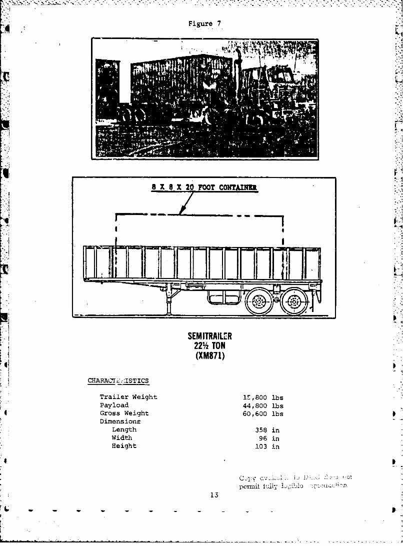
-4 Figure 7
Al
8 X 8 X 20 FOOT CONTAINER
I-fl
SEMITRAILER22% TON
(XM871)
CHARACrK'_-,-ISTICS
Trailer Weight 1E,800 lbsPayload 44,800 lbsGross Weight 60,600 lbsDimensions
Length 358 inWidth 96 inHeight 103 in
penuit ly !-lll ' V('t, (". l
13

Figure 8
., 1, M
TRACTOR
5-TON, 6x6
(M818)
CHARACTERISTICS
W0/W W/W
Federal Stock No. 2320-050-8984 2320-050-8978Gross Combination Weight, 75,690 lbs 76,355 lbs
Payload and CrewShipping Dimensions
Length 264 in 280 inWidth 97 in 97 inHeight 116 in 116 in
Maximum Speed -52 MPHMaximum Grade 42%Cruising Range 350 milesFuel Diesel (3.2MPG)Air Transport Classification Phase II U~nladen
Copy available to DTIC does notper'nit fully legiblo ieproductjon
14

(2) Sea Water Pretreatment
*RO (33% water recovery)Post Chlorination 1
NOTE: Filter back wash accomplishedwith RO waste brine
(3) Brackish water PretreatmentCoagulationFiltration
RO (45& water recovery)Post ChlorinationNOTE: Filter back wash accomplished
with RO waste brine
(4) Water contaminated Same as for Problem Water 3* with nuclear warfare agent
(5) water contaminated with Same as for Problem Water 1 1* biological warfare agent
(6) Water contaminated with Same as for Problem Water 3chemical warfare agent
Taking into account the above operational modes, plus the effects of temperature,backwash requirements, 20 hour operational day, etc., the projected true outputof the machine is shown in Table 2.
The schedule for the development of the 3 000/2000 GPH ROWPU is shown in Figure 9.
.7,,
"Did I have a nightmare last night! Idreamed that they had a thousand RO unitsand we had only a hundred."
15 J
w ~~ ~ . .w . . . . . . .

41§
in M N
c- C4%a0 e.o c
5441
9 E-4
04 0
00 C:N0 0H4j0 c J r
.,4 41N4 0 4 4 . 1 -
04$4fdr- 5I 0 e4 M $4 r-4IV2541
P4TA11 0'o54 00of 0404
41 4
4J 0.4V 4) 40
P-.04 ld $4 f-4 9: iU5 54 a to he 0 0 54
04 $ A 4 a 4 I
E- I -ý (d - 11
1604r

r44
0.00
w. wo wo w co GO o 00 ao go 00 co Go CIO ao wo w Co Co Go aco C 00C4. W-. 0.4. > $4 ba" U. c0. >
CL C4 Q N O 4 Cm 0 4 0-4 0 N4 V.4 P4 N 0-4 0(0 0 CO
P co aI so o o o c a m co a co ao a a* a a* a a A co ao a*~14 04 02 0- 4 '-4 4 m > 14 04 bN > N .
cu 0 a 0
un -O4 0 0 4 V N 'qi I( 0 Oh %0(N 0 n P') 4 "4 -4 ý N N- 04 O N N- N- - -
bl 4 10 IA
F- Ig
4..
*1 I-4 1. L
.*0 0 03t 4. 0. 1.4 IL
4. 0 4. (6 'Inn4.o 4.'d 41 J U 4. 6
g gI 4' *' 14 :1 a.a EU N UI- a 0 1-.4 Q
0 10 j 4 J +j 1 J 4 0 0 41 IL 4- 4 a - 41-H0c 0 E4 =4 ý4 =-d
., 0 W0~4000 4 10 $4 00 0 0 0 4 0 0 1 .4.4 co
O u0 .4l~ 00 tO 0~ U~ &40
17 Q 0 0 0- ao C 0 N a, 0 CI.. 4
>- - -- -4-4-o -- -4 -4 .- - --
4-a

Opp
4) .
VIC