dk fr de series...• ventilstyringen 2224 er en mikroprocessor-styret enhed, som indeholder...
TRANSCRIPT

Programmable displays with a wide se-lection of inputs and outputs for display of temperature, volume and weight, etc. Feature linearisation, scaling, and difference measurement functions for programming via PReset software.
Interfaces for analogue and digitalsignals as well as HART® signals between sensors / I/Pconverters / frequency signals and control systems in Ex zone 0, 1 & 2 and for some modules in zone 20, 21 & 22.
Galvanic isolators for analogue and digital signals as well as HART® signals. A wide product range with both loop-powered and universal isolators featuring linearisation, inversion, and scaling of output signals.
PC or front programmable modules with universal options for input, output and supply. This range offers a number of advanced features such as process calibration, linearisation and auto-diagnosis.
A wide selection of transmitters for DIN form B mounting and DIN rail modules with analogue and digital bus communication ranging from application-specifi c to universal transmitters.
Displays
Temperature
Isolation
Ex barriers
Universal
DK
UK
FR
DE
Side 1
Page 19
Page 37
Seite 55
S I G N A L S T H E B E S T
2 2 2 4
V a l v e C o n t r o l l e r
N o . 2 2 2 4 V 1 0 2 - I N ( 0 6 0 6 )F r o m s e r . n o . 0 1 0 3 5 2 0 0 1
VENTILSTYRING
TYPE 2224
INDHOLDSFORTEGNELSE
Overensstemmelseserklæring ............................................ 2Adskillelse af SYSTEM 2200 .............................................. 3Anvendelse ......................................................................... 4Teknisk karakteristik ........................................................... 4Indgang .............................................................................. 5Udgang ............................................................................... 5Bestillingsskema ................................................................. 5Elektriske specifikationer ................................................... 6Blokdiagram ....................................................................... 7Timing diagram .................................................................. 8DIP-switchprogrammering ................................................. 8Fortrådningsdiagrammer for joystick / potentiometerindgang ................................................... 10Fortrådningsdiagrammer for DC strømindgang ................. 11Fortrådningsdiagrammer for DC spændingsindgang ........ 12Teknisk beskrivelse ............................................................ 13Rutediagram ....................................................................... 14Programmering / Betjening af trykknapper ........................ 16
1

ADSKILLELSE AF SYSTEM 2200
Billede 1.Modulets bagplade frigøres fra huset ved hjælp af en skruetrækker.
Billede 2.Bagpladen kan udtrækkes sammen med printet, men vær opmærksom på printets placering i huset, da det er muligt at isætte dette i flere posi-tioner. Træk ikke unødigt i lednin-gerne, men tag fat i printet.Nu kan switche og jumpere ændres. Det er vigtigt, at ingen ledninger kommer i klemme, når bagplade og huset samles.
3
OVERENSSTEMMELSESERKLÆRINGSom producent erklærer
PR electronics A/S
Lerbakken 10
DK-8410 Rønde
hermed at følgende produkt:
Type: 2224
Navn: Ventilstyring
er i overensstemmelse med følgende direktiver og standarder:
EMC-direktivet 2004/1086/EF og senere tilføjelser
EN 61326
Denne erklæring er udgivet i overensstemmelse med EMC-direktivets paragraf 10, stk. 1. For specifikation af det acceptable EMC-niveau henvises til modu-lets elektriske specifikationer.
Rønde, 6. feb. 2006 Peter Rasmussen Producentens underskrift
2

• Udgangsstrømmen aktiveres / afbrydes med et digitalt styresignal. Vær derfor opmærksom på, at udgangsstrømmen er afbrudt, indtil +Vforsyning påtrykkes terminal 3.
Indgang:
• Programmerbar strøm- eller spændingsindgang for standardsignaler i henhold til ordreskema, joystick / potmeter eller speciel ikke-programmerbar indgang.
• Enheden har digitale indgange for eksterne styrefunktioner.
Udgang:
• Pulserende strømudgang sikrer, at den tilsluttede ventil ikke hænger.
• Modulationsfrekvensen (PWM) kan frit programmeres mellem 8 og 400 Hz.
• Det interne måle- & reguleringskredsløb sikrer, at middelstrømmen aldrig over-stiger den indtastede Iventil.
• Hvis peak-strømmen overstiger 7 A, lukkes udgangen ned, så den ingen strøm afgiver.
5
VENTILSTYRING 2224
• Programmerbar via frontknapper• mA, V, Ω programmerbar indgang• Rampetider, springværdier, invertering, chopper - frekvens og dødbånd• 3-cifret LED-display viser % af Iventil• 1 eller 2 kanaler• Moduleret strømudgang for proportionalventilAnvendelse:
• Styring og regulering af enkelt- eller dobbeltspolede hydrauliske og pneumati-ske proportionalventiler.
• Enheden anvendes, hvor der stilles krav om nøjagtig oliestrømsregulering, line-ær blød acceleration og deceleration, moduleret udgangssignal og program-merbart dødbånd.
• Er yderst velegnet til joystick-regulering af A/B bevægelse.
Teknisk karakteristik:
• Ventilstyringen 2224 er en mikroprocessor-styret enhed, som indeholder ram-pefunktioner til blød start og stop og springfunktioner således, at dødbånd undgås ved start og ved skift mellem A & B ventil.
• Ventilstyringens brugerinterface består af tre trykknapper og et 3-cifret LED-display. Via dette ændres udgangsstrømme, rampetider, springværdier, chop-per-frekvens, invertering, dødbånd og on/off rampefunktion.
• Under drift vil displayet vise aktuelt udgangssignal som % af Iventil.
• Alle parametre er password-beskyttet mod uautoriserede ændringer.
• Skift mellem A og B ventil kan ske på to måder. Ved funktion 1 vælges A ventil ved påtrykning af +Vforsyning på terminal 2. Ved funktion 2 sker skift mellem A / B ventil automatisk i henhold til indgangssignalets værdi (intet signal på terminal 2).
4

BLOKDIAGRAM
7
Elektriske specifikationer:Specifikationsområde:-20°C til +60°CFælles specifikationer:Forsyningsspænding ................................... 9,6...14,4eller 19,2...28,8 VDCEgetforbrug ................................................. 2 W / 24 V 1,8 W / 12 VKommunikation ........................................... FrontprogrammeringOpdateringstid ............................................. 30 msTemperaturkoefficient .................................. 0,01% / °CLinearitetsfejl ............................................... 0,2%EMC-immunitetspåvirkning ......................... < 2% af spanRelativ luftfugtighed .................................... < 95% RH (ikke-kond.)Mål (HxBxD) ................................................ 80,5 x 35,5 x 84,5 mmTæthedsgrad ............................................... IP50Vægt ............................................................ 160 gIndgang:Strømindgang .............................................. 0/4...20 mA / 50 Ω + PTC (54 Ω)Spændingsindgang ..................................... 0/0,2...1 V og 0/2...10 V / 10 MΩPotentiometerindgang ................................. 0...10 V eller ± 10 V / 10 kΩEksternt potentiometer ................................ 1 kΩ ≤ potmeter ≤ 10 kΩStyresignaler:Drift / stilstand ............................................. PNP / 2,2 kΩ, 12 / 24 VImax1 og Imax2 ........................................... PNP / 2,2 kΩ, 12 / 24 VA / B kanal ................................................... PNP / 2,2 kΩ, 12 / 24 VDødbånd ...................................................... 0...99,9% af indgangsspanUdgang:Udgangsspænding (max.) ........................... Forsyningsspænding -0,5 VUdgangsstrøm (max.) .................................. 3000 mA middelStrøm-peak ................................................. 7 AUdgangseffekt (max.) .................................. 36 WReferencespænding .................................... 10 VDC (A ventil) ± 10 VDC (A & B ventil)Rampe op & ned ......................................... Tid 0...10,0 sPWM-frekvens ............................................. 8...400 Hz i spring af 1 HzGOST R godkendelse:VNIIM ........................................................... Cert. no. Ross DK.ME48.V01899Overholdte myndighedskrav: Standard:EMC 2004/108/EF Emission og immunitet ....................... EN 61326
Af span = Af det aktuelt valgte område
6

9
TIMING-DIAGRAM
DIP-switchprogrammering:Med DIP-switchindstillingen vælges både indgangssignalet og funktionen.Funktion 1:Enkelt- og dobbelt ventilstyring. Ved dobbelt ventilstyring vælges A ventil ved at påtrykke +Vforsyning på terminal 2. Funktion 2:Dobbelt ventilstyring med automatisk skift mellem A og B ventil (intet signal på terminal 2).
Indgang: 0...50% = A ventil 100...0%.Indgang: 50...100% = B ventil 0...100%.
8

FORTRÅDNINGSDIAGRAMMER FORDC STRØMINDGANG
Dobbelt ventilstyring med0...20 mA indgangssignal.DIP-switchprogrammering:Funktion 1 ellerFunktion 2.
Enkelt ventilstyring med 4...20 mA indgangssignal.DIP-switchprogrammering:Funktion 1.
11
FORTRÅDNINGSDIAGRAMMER FOR JOYSTICK- / POTENTIOMETERINDGANG
Dobbelt ventilstyring via +/- 10 VDC referencespænding.DIP-switchprogrammering:Funktion 2.
Dobblet ventilstyring via + 10 VDC referencespænding.DIP-switchprogrammering:Funktion 1 ellerFunktion 2.
Enkelt ventilstyring via + 10 VDC referencespænding.DIP-switchprogrammering:Funktion 1.
10
TEKNISK BESKRIVELSE• For at hindre at programmering kan ske under drift, er der indlagt to sik-
kerhedsforanstaltninger. Det korrekte password (030) skal indtastes i menuen [PAS], og udgangen må ikke give signal (displayet skal vise 000). Dette opnås ved at afbryde +Vforsyning på terminal 3.
• Enheden kan styres med joystick / potentiometer, tilsluttet den interne +10V og evt. -10V forsyning, eller et proces strøm- / spændingssignal. Benyttes processignal, kan indgangen kobles som differentialforstærker (DP1 switch 6 off) og modvirke potentialefejl på grund af uhensigtmæssig jording. Ved joystick- / potentiometerindgang skal indgangen kobles single-ended (stellet), og der er mulighed for at indkoble en 10kΩ belastningsmodstand (DP1 switch 5 on), så der altid går strøm i potentiometerets glidekontakt.
• Skift mellem A / B ventil kan ske på to måder. Ved funktion 1 vælges A ventil ved påtrykning af +Vforsyning på terminal 2. Ved funktion 2 sker skift mellem A / B ventil automatisk i henhold til indgangssignalets værdi (intet signal på terminal 2). Indgang: 0...50% = A ventil 100...0%. Indgang: 50...100% = B ventil 0...100%.
• Ved tilslutning af ventilspole er det vigtigt at sikre, at impulsstrømmen =Vfors. / Rspole ikke overskrider den tilladte spidsværdi på 7A.
• For at undgå utilsigtet betjening i forbindelse med f.eks. en upræcis neu-tral stilling på et joystick er det muligt at programmere et dødbånd. Dette dødbånd bevirker, at indgangen skal over et vist niveau, inden udgangen reagerer.
• Der er mulighed for at indstille springrespons (bias), således at der tages højde for ventilsædets vandring, inden der er oliegennemstrømning.
• Man har mulighed for at programmere to faste maksimalstrømme (Imax1 & Imax2). Skiftet mellem de to strømme sker med et eksternt PNP-signal på terminal 7. Funktionen kan bl.a. anvendes i forbindelse med endestop, såle-des at den sidste vandring sker langsomt.
• Ventilstyringen overholder EMC-data, når installationskablet til tilsluttede ventiler er skærmet. Skærmen forbindes til forsyningsground.
13
FORTRÅDNINGSDIAGRAMMER FOR DC SPÆNDINGSINDGANG
Dobbelt ventilstyring med 0...1 VDC indgangssignal. DIP-switch-programmering:Funktion 1 ellerFunktion 2.
Enkelt ventilstyring med 0...1 VDC indgangssignal.DIP-switchprogrammering:Funktion 1.
Dobbelt ventilstyring med -10...+10 VDC indgangssignal.DIP-switchprogrammering:Funktion 1 ellerFunktion 2.
12

1514

0.0. Normal tilstand - displayet viser udgangsværdi i procent af Iventil.
Displayet går til denne tilstand ved power ON, eller hvis ingen taster har været aktiveret i en periode på 2 minutter.
1.0 VAL - Indtastning af password.
1.1 PAS - Programmeringsadgang. Accepteret password gælder, indtil forsyningsspændingen afbrydes.Password er 030.
2.0 CUA - Indstilling af strømme for ventil A.
2.1 LOA - Springrespons for ventil A.Indstilles i procent af Iventil.Lovlige valg er 0...99,9%.
2.2 IA1 - Strømbegrænsning Imax1.Indstilles i procent af Iventil.Lovlige valg er 0...99,9%.
2.3 IA2 - Strømbegrænsning Imax2.Indstilles i procent af Iventil.Lovlige valg er 0...99,9%.
3.0 CUB - Indstilling af strømme for ventil B.
Indstilles på samme måde som for ventil A.
4.0 RAN - Indstilling af rampeparametre.
4.1 ON - Valg af rampe on/off.1 = rampe aktiv, 0 = rampe afbrudt.Lovlige valg er 0 eller 1.
4.2 UP - Indstilling af rampetid op.Indstilles i sekunder.Lovlige valg er 0...10 s.
4.3 DO - Indstilling af rampetid ned.Indstilles i sekunder. Lovlige valg er 0...10 s.
17
PROGRAMMERING / BETJENINGAF TRYKKNAPPER
DOKUMENTATION TIL RUTEDIAGRAM
Generelt: Programmeringen er menustyret. Hovedmenuerne er nummereret i niveau 0 (X.0), og undermenuerne i niveau 1 (X.1...X.4). Til hver undermenu findes en indtastningsmenu. Opbygningen er udført, så de menuer, der anvendes oftest, ligger nærmest normaltilstanden menu 0.0. Vær opmærksom på, at programmering kun er mulig, når der i undermenu 1.1 PAS indtastes værdien 030.Alle foretagne ændringer gemmes først i EEPrommen, når der returneres til normaltilstanden - menu 0.0.
Man finder rundt i underprogrammet og sidegrenene ved hjælp af de 3 taster 3,1 og 2.
Rutedi agram met viser tasternes funktion.
I sidegrenene vil tryk på 2 gå til indtast-nings- / parametervalgmenu, hvor aktuel værdi vises.
I indtastningsmenuer vil ciffer, der kan ændres, blinke.
Blinkende cifferposi tion flyttes med 3 tasten, og cifferets værdi ændres med 1 tasten.
Når kommaet blinker, kan placeringen ændres med 1 tasten.
I parametervalgmenuer skiftes mellem parametrene med 1.
Gem midlertidigt ved at trykke 31 samtidigt.Gem alle ændringer permanent ved at gå til menu 0.0.
Forlad indtastningsmenu uden at gemme - tryk på 2.
16

VALVE CONTROLLER
TYPE 2224
CONTENTS
Declaration of Conformity .................................................. 20How to dismantle SYSTEM 2200 ....................................... 21Applications ........................................................................ 22Technical characteristics .................................................... 22Input ................................................................................... 23Output ................................................................................ 23Order .................................................................................. 23Electrical specifications ...................................................... 24Block diagram .................................................................... 25Timing diagram .................................................................. 26DIP-switch programming ................................................... 26Wiring diagrams for joystick / potentiometer input ....................................................... 28Wiring diagrams for DC current input ................................ 29Wiring diagrams for DC voltage input ................................ 30Technical description ......................................................... 31Routing diagram ................................................................. 32Programming / Operating the function keys ...................... 34
19
5.0 PAR - Indstilling af parametre for udgang.
5.1 REV - Valg af direkte / inverteret udgang.0 = direkte, 1 = inverteret.Lovlige valg er 0 eller 1.
5.2 DOD - Indstilling af dødbånd for f.eks. joystick.Indstilles i % af indgangsspan.Lovlige valg er 0...99,9%.
5.3 FRQ - Indstilling af modulationsfrekvens for udgangsstrøm.Indstilles i Hz. Lovlige valg er 8...400 Hz.
5.4 GA - Indstilling af Iventil.Indstilles i ampere - med 2 decimaler.Lovlige valg er 0...3,00 A
6.0 PRO - Produktion.
OBS! Værdier må ikke ændres!Hovedmenu med undermenuer, som PR electronics A/S anvender til opsætning og kalibrering af 2224.
18

HOW TO DISMANTLE SYSTEM 2200
Picture 1.The back panel of the module is detached from the housing by way of a screwdriver.
Picture 2. After this, the back panel can be pulled out together with the PCB, but please notice the position of the PCB as there is a number of dif-ferent positions in the house. Do not pull the wires unnecessarily, instead pull the PCB. Switches and jumpers can now be moved. When assem-bling the back plate and housing, please make sure no wires are stuck.
21
DECLARATION OF CONFORMITYAs manufacturer
PR electronics A/S
Lerbakken 10
DK-8410 Rønde
hereby declares that the following product:
Type: 2224
Name: Valve Controller
is in conformity with the following directives and standards:
EMC directive 2004/108/EC and later amendments
EN 61326
This declaration is issued in compliance with article 10, subclause 1 of the EMC directive. For specification of the acceptable EMC performance level, refer to the electrical specifications for the module.
Rønde, 6 Feb. 2006 Peter Rasmussen Manufacturer’s signature
20

• The output current is enabled / disabled by a digital controlling signal. Please note that the output current is disconnected until +Vsupply is applied to termi-nal 3.
Input:
• Programmable current or voltage input for standard signals acc. to order schedule, joystick / potentiometer or a special non-programmable input.
• Digital inputs for external control functions.
Output:
• A pulsating current output prevents the connected valve from sticking.
• Optional programming of the modulation frequency (PWM) between 8 and 400 Hz.
• The internal measuring and control circuit ensures that the mean current never exceeds the entered Ivalve.
• If the peak current ex ceeds 7 A the output will be disabled.
23
VALVE CONTROLLER 2224
• Front-programmable• mA, V, and Ω-programmable input• Ramp times, jump values, reversal, chopper frequency, and deadband• 3-digit LED display shows Ivalve % value• 1 or 2 channels• Modulated current output for proportional valveApplications:
• Control and regulation of single or double-coil hydraulic and pneumatic pro-portional valves.
• The unit is used for accurate oil flow regulation, linear soft acceleration and deceleration, modulated output signal, and programmable deadband.
• Is highly suitable for joystick regulation of A/B movements.
Technical characteristics:
• The 2224 Valve Controller is a microprocessor-based unit containing ramp functions for soft start and stop and jump functions thus avoiding deadband at start and changes between A & B valves.
• The user interface of the valve controller consists of three pushbuttons and a 3-digit LED display. By using these, output currents, ramp times, jump values, chopper frequency, reversal, deadband, and on/off functions are changed.
• During operation the display shows the present output signal as a % of the Ivalve.
• All parameters are protected against unauthorised changes with a password.
• Changes between A and B valves can be made in two ways. By way of function 1, the A valve is chosen when +Vsupply is applied to terminal 2. By way of function 2, changes between A/B valves take place automatically according to the value of the input signal (no signal on terminal 2).
22

BLOCK DIAGRAM
25
Electrical specifications:
Specifications range:-20°C to +60°C
Common specifications:Supply voltage ............................................ 9.6...14.4 or 19.2...28.8 VDCInternal consumption .................................. 2 W / 24 V 1.8 W / 12 VCommunication ........................................... Front-programmableUpdating time .............................................. 30 msTemperature coefficient ............................... 0.01%/°CLinearity error .............................................. 0.2%EMC immunity influence ............................. < 2% of spanRelative air humidity .................................... < 95% RH (non-cond.)Dimensions (HxWxD) ................................... 80.5 x 35.5 x 84.5 mmTightness ..................................................... IP50Weight ......................................................... 160 gInput:Current input ............................................... 0/4...20 mA / 50 Ω + PTC (54 Ω)Voltage input ............................................... 0/0.2...1 V and 0/2...10 V / 10 MΩPotentiometer input ..................................... 0...10 V or ±10 V / 10 kΩExternal potentiometer ................................ 1 kΩ ≤ potentiometer ≤ 10 kΩControl signals:Operation / shutdown ................................. PNP / 2.2 kΩ, 12 / 24 VImax1 & Imax2 ............................................. PNP / 2.2 kΩ, 12 / 24 VA / B channel ............................................... PNP / 2.2 kΩ, 12 / 24 VDeadband .................................................... 0...99.9% of input spanOutput:Output voltage (max.) .................................. Supply voltage -0.5 VOutput current (max.) .................................. 3000 mA meanCurrent peak ................................................ 7 AOutput power (max.) ................................... 36 WReference voltage ....................................... 10 VDC (A valve) ±10 VDC (A & B valve)Ramp up & down ........................................ Time 0...10.0 sPWM frequency ........................................... 8...400 Hz in steps of 1 HzGOST R approval:VNIIM ........................................................... Cert. no. Ross DK.ME48.V01899Observed authority requirements: Standard:EMC 2004/108/EC Emission and immunity ....................... EN 61326Of span = Of the presently selected range
24

27
TIMING DIAGRAM
DIP-switch programming:Input signal and function are chosen via the DIP-switch setting.Function 1:Single and double valve control. By double valve control, A valve is chosen by applying +Vsupply to terminal 2.Function 2:Double valve control with automatic change between A and B valves (no signal on terminal 2).
Input: 0...50% = A valve 100...0%.Input: 50...100% = B valve 0...100%.
26

WIRING DIAGRAMS FORDC CURRENT INPUT
Double valve control (A/B valves) from a 4...20 mAinput signal. DIP-switch programming:Function 1 orFunction 2.
Single valve control froma 4...20 mA input signal.DIP-switch programming:Function 1.
29
WIRING DIAGRAMS FOR JOYSTICK /POTENTIOMETER INPUT
Double valve control (A/B valves) from +/-10 VDCreference supply.DIP-switch programming:Function 2.
Double valve control (A/B valves) from +10 VDCreference supply.DIP-switch programming:Function 1 orFunction 2.
Single valve control from +10 VDC reference supply.DIP-switch programming:Function 1.
28

TECHNICAL DESCRIPTION• To prevent programming during operation, two safety measures have been
included: The correct password (030) must be entered in menu [PAS], and the output must give no signal (000 must be displayed). This is achieved by disconnecting +Vsupply on terminal 3.
• The 2224 Valve Controller can be controlled by a joystick / potentiometer using the internal +10 V and -10 V supply, or a process current / voltage signal. For process signals the differential amplifier (DP1 switch 6 off) will pre-vent potential electrical error due to improper grounding. Joysticks / potentio-meters are connected single-ended (grounded), and it is possible to connect a 10 kΩ load resistor (DP1 switch 5 on), providing a minimum potentiometer load current.
• A switch between A and B valves can be made in two ways. By way of function 1, the A valve is chosen when +Vsupply is applied to terminal 2. By way of function 2, changes between A/B valves are made automatically according to the value of the input signal (no signal on terminal 2). Input: 0...50% = A valve 100...0%. Input: 50...100% = B valve 0...100%.
• When connecting the output to a solenoid please ensure that the peak valve current = Vsupply / Rsolenoid does not exceed 7A.
• A deadband can be programmed to avoid unintentional activation of the valve in connection with e.g. an inaccurate neutral position of joysticks. The deadband introduces a threshold which must be exceeded before any output activity will take place.
• The spring response (bias) can be adjusted to account for the valve seat travel before oil flow.
• Two current limits can be programmed (Imax1 & Imax2) for limit stop detection featuring slow motion before stop. The active current limit (Imax1 & Imax2) is selected by the PNP input signal on terminal 7.
• The 2224 Valve Controller complies with EMC data only when shielded cabling is used and the shield is connected to supply ground.
31
WIRING DIAGRAMS FORDC VOLTAGE INPUT
Double valve control (A/B valves) from a 0...1 VDCinput signal.DIP-switch programming:Function 1 orFunction 2.
Single valve control froma 0...1 VDC input signal.DIP-switch programming:Function 1.
Double valve control (A/B valves) from a -10...+10VDC input signal.DIP-switch programming:Function 1 orFunction 2.
30

3332

0.0. DEFAULT - Output percentage value of Ivalve is displayed.
At power ON, or if no keys have been activated for a period of 2 minutes, the display returns to default.
1.0 VAL - Enter password.
1.1 PAS - Programming access.Accepted password is valid until power off. The password is 030.
2.0 CUA - Setting of currents for A valve.
2.1 LOA - Spring response for A valve.The parameter is entered as a percentage of the Ivalve.Valid selections are 0...99.9%.
2.2 IA1 - Current limit Imax1.The parameter is entered as a percentage of the Ivalve.Valid selections are 0...99.9%.
2.3 IA2 - Current limit Imax2.The parameter is entered as a percentage of the Ivalve.Valid selections are 0...99.9%.
3.0 CUB - Setting of currents for B valve.
Please see the setup of the A valve (2.0 CUA).
4.0 RAN - Setting of ramp parameters.
4.1 ON - Selection of on/off ramp.1 = ramp enable, 0 = ramp disable.Valid selections are 0 or 1.
4.2 UP - Setting of ramp time up.The ramp time is set in seconds.Valid selections are 0...10 s.
4.3 DO - Setting of ramp time down.The ramp time is set in seconds.Valid selections are 0...10 s.
35
PROGRAMMING / OPERATINGTHE FUNCTION KEYS
DOCUMENTATION FOR ROUTING DIAGRAM
General:The programming is menu-controlled. The main menus are numbered in level 0 (X.0), and the submenus are numbered in level 1 (X.1 to X.4). Each submenu has an accompanying entry menu. The menus are structured in such a way that the menus most frequently used are closer to the default menu 0.0. Please note that programming is only possible when submenu 1.1 PAS has the value 030. All changes are not permanently saved in the EEP rom, until you return to menu 0,0.
Menus and submenus are selected by the 3 function keys 3, 1, and 2 as outlined in the routing diagram.
Activating 2 in the submenu will display the current value in the entry menu.In entry menus, the digit that can be changed will flash.
Active digit position is shifted by the 3 key, and the value is changed by the 1 key.When the decimal point flashes, its position can be changed by the 1 key.
In parameter selection menus you switch between the parameters by using the 1 key.
To store changes temporarily press 31 simultaneously.To store changes permanently go to menu 0,0. To return to the previous menu without changing the parameters - press 2.
34

REGULATEUR DE VANNE
TYPE 2224
SOMMAIRE
Déclaration de conformité .................................................. 38Démontage du SYSTEME 2200 ......................................... 39Applications ........................................................................ 40Caractéristiques techniques .............................................. 40Entrée ................................................................................. 41Sortie .................................................................................. 41Commande ......................................................................... 41Spécifications électriques .................................................. 42Schéma de principe ........................................................... 43Diagramme de fonctionnement .......................................... 44Configuration des commutateurs ...................................... 44Schémas de raccordement : entrée manette / potentiomètrique ............................................................ 46Schémas de raccordement pour entrée courant cc .......... 47Schémas de raccordement pour entrée tension cc .......... 48Description technique ........................................................ 49Diagramme de programmation .......................................... 50Programmation / Utilisation des touches de fonction ....... 52
37
5.0 PAR - Setting of parameters for output.
5.1 REV - Selection of direct / inverted output.0 = direct, 1 = inverted.Valid selections are 0 or 1.
5.2 DOD - Setting of deadband for e.g. joystick.The parameter is entered as a percentage of the input span.Valid selections are 0...99.9%.
5.3 FRQ - Setting of modulation frequency for output current.The frequency is set in Hz. Valid selections are 8...400 Hz.
5.4 GA - Setting of Ivalve.The parameter is set in Ampere - with two decimals.Valid selections are 0...3.00 A
6.0 PRO - Production.
NB! The factory settings must not be changed.Main menu with submenus that PR electronics A/S use for the set-up and calibration of the 2224 Valve Controller.
36

DEMONTAGE DU SYSTEME 2200
Figure 1.A l’aide d’un tournevis, dégagez la face arrière du module du boîtier.
Figure 2.Vous pouvez maintenant extraire la face arrière du module ainsi que la carte à circuits imprimés. Veuillez repérer la position de cette carte car il existe de nombreuses positions possibles dans le boîtier. Lorsque vous extrayez la carte à circuits imprimés, tirez sur celle-ci et évitez de tirer sur les fils. Vous pouvez maintenant déplacer les commuta-teurs et les cavaliers. Lorsque vous assemblez la face arrière du module et le boîtier, veuillez vérifier que les fils ne sont pas coincés.
39
DECLARATION DE CONFORMITEEn tant que fabricant
PR electronics A/S
Lerbakken 10
DK-8410 Rønde
déclare que le produit suivant :
Type : 2224
Nom : Regulateur de vanne
correspond aux directives et normes suivantes :
La directive CEM (EMC) 2004/108/CE et les modifications subséquentes
EN 61326
Cette déclaration est délivrée en correspondance à l’article 10, alinéa 1 de la directive CEM. Pour une spécification du niveau de rendement acceptable CEM (EMC) renvoyer aux spécifications électriques du module.
Rønde, le 6 février 2006 Peter Rasmussen Signature du fabricant
38

• Le décalage entre les vannes A et B peut être réalisé comme suit : Par la fonc-tion 1, la vanne A est choisie en appliquant le + de la tension d’alimentation à la borne 2. Par la fonction 2, le décalage entre A/B se fait automatiquement par rapport à la valeur du signal d’entrée (pas de signal sur la borne 2).
• La sortie courant est activée ou désactivée par un signal d’entrée digital. Veuillez noter que le courant de sortie est coupé jusqu’à ce que le + de la tension d’alimentation soit raccordé à la borne 3.
Entrée :
• Tension ou courant programmable pour des signaux standards, manette potentiométrique ou entrée spéciale non programmable.
• Entrées digitales pour les fonctions de contrôle externes.
Sortie :
• La sortie courant hachée évite le blocage de la vanne.
• La fréquence de modulation (PWM) peut être programmée entre 8 et 400 Hz.
• Les circuits de mesure et régulation interne assurent au courant moyen de ne pas excéder la valeur entrée : Ivanne.
• Si le courant de pointe excède 7A, la sortie sera désactivée.
41
REGULATEUR DE VANNE 2224
• Programmable en face avant• Entrée programmable : mA, V, Ω • Rampes, offset de démarrage, inversion, fréquence du hacheur et bande morte• Affichage LED 3-chiffres indication de Ivanne en %• 1 ou 2 voies• Courant de sortie moduléApplications :
• Contrôle et régulation de vannes / distributeurs hydrauliques et pneumatiques à bobinage simple ou double.
• Ce module est utilisé pour la régulation précise du débit d’huile avec les pos-sibilités suivantes : accélération et décélération linéaires progressives, signal de sortie modulé et bande morte programmable.
• Le régulateur de vanne 2224 est idéal pour la régulation de mouvements A/B par manettes potentiométriques.
Caractéristiques techniques :
• Le régulateur de vanne 2224 fonctionne sur la base d’un microprocesseur et permet le démarrage et l’arrêt progressif grâce aux fonctions de rampes. Les fonctions sauts évitent la bande morte au démarrage et le décalage entre les vannes A et B.
• L’interface utilisateur est constituée de 3 boutons-poussoirs et d’un affichage LED 3-chiffres. Ainsi, tous les paramètres tels que le courant de sortie, les rampes, les valeurs de sauts, la fréquence du hacheur, l’inversion, la bande morte et la fonction de rampe ON/OFF sont modifiables en face avant.
• En fonctionnement l’affichage indique le signal de sortie actuel en % de la Ivanne.
• Tous les paramètres sont protégés par un mot de passe contre les modifica-tions non autorisées.
40

SCHÉMA DE PRINCIPE
43
Spécifications électriques :
Plage des spécifications :-20°C à +60°CSpécifications communes :Tension d’alimentation ................................ 9,6...14,4 ou 19,2...28,8 VccConsommation interne ................................ 2 W / 24 V 1,8 W / 12 VConfiguration ............................................... Programmable en face avantTemps de réponse ....................................... 30 msCoefficient de température ......................... 0,01% / °CErreur de linéarité ........................................ 0,2%CEM (EMC) : Effet de l’immunité ................ < 2% de l’ECHumidité relative ......................................... < 95% HR (sans cond.)Dimensions (HxLxP) .................................... 80,5 x 35,5 x 84,5 mmEtanchéité .................................................... IP50Poids ........................................................... 160 gEntrée :Entrée courant ............................................. 0/4...20 mA / 50 Ω + PTC (54 Ω)Entrée tension ............................................. 0/0,2...1 V et 0/2...10 V / 10 MΩEntrée potentiomètre ................................... 0...10 V ou ±10 V / 10 kΩPotentiomètre externe ................................. 1 kΩ ≤ potentiomètre ≤ 10 kΩSignaux de contrôle :Opération / arrêt .......................................... PNP / 2,2 kΩ, 12 / 24 VImax1 et Imax2 ............................................ PNP / 2,2 kΩ, 12 / 24 VVanne A / B ................................................. PNP / 2,2 kΩ, 12 / 24 VBande morte ................................................ 0...99,9% de l’ECSortie :Sortie tension (max.) ................................... Tension d’alimentation -0,5 VSortie courant (max.) ................................... 3000 mA moyen Crête courant .............................................. 7 APuissance de sortie (max.) .......................... 36 WTension de référence ................................... 10 Vcc (vanne A) ±10 Vcc (vanne A & B)Temps de monté et de descente ................ 0...10,0 sFréquence PWM ......................................... 8...400 Hz par pas de 1 HzApprobation GOST R :Standard : VNIIM ......................................... Cert. no. Ross DK.ME48.V01899Agréments et homologations : Standard :CEM (EMC) 2004/108/CE Emission et immunité ............ EN 61326EC = Echelle configurée
42
45
DIAGRAMME DE FONCTIONNEMENT
Configuration des commutateurs :Le signal d’entrée et les fonctions sont choisis à l’aide de commutateurs.Fonction 1 :Contôle de vanne simple ou double. Dans le cas de contrôle d’une vanne double, la vanne A est choisie en raccordant le +de la tension d’alimentation à la borne 2.Fonction 2 :Contrôle de vanne double avec changement automatique entre les vannes A et B (pas de signal sur la borne 2).
Entrée : 0...50% = vanne A 100...0%.Entrée : 50...100% = vanne B 0...100%.
44

DIAGRAMMES DE RACCORDEMENT POUR L’ENTRÉE COURANT CC
Contrôle double par un signal d’entrée de 4...20 mA. Configuration des commuta-teurs :Fonction 1 ouFonction 2.
Contrôle unique par un signal d’entrée de 4...20 mA.Configuration des commuta-teurs :Fonction 1.
47
DIAGRAMMS DE RACCORDEMENT POUR ENTRÉE MANETTE / POTENTIOMÈTRE
Contrôle double par tension de référence de +/- 10 Vcc. Configuration des commuta-teurs : Fonction 2.
Contrôle double par tension de référence de +/- 10 Vcc. Configuration des commuta-teurs : Fonction 1 ouFonction 2.
Contrôle double par tension de référence de +/- 10 Vcc. Configuration des commuta-teurs : Fonction 1.
46
DESCRIPTION TECHNIQUE• Pour plus de sûreté, une double sécurité protège l’accès à la programmation.
Afin de pouvoir programmer l’appareil, le code 030 doit être présent dans le sous-menu 1.1 et la sortie ne doit pas donner de signal (affichage de 000). Cela est obtenu en coupant le + de la tension d’alimentation de la borne 3.
• Le PR-2224 peut être contrôlé par une manette / un potentiomètre en utilisant l’alimentation interne de +10 V ou ±10 V, ou un signal courant / tension. Pour les signaux de contrôle, l’entrée peut être connectée comme un amplificateur différentiel (DP1 switch 6 off) et ainsi neutraliser des erreurs électriques dues à la connexion à la masse. L’entrée manette / potentiomètre est non-chargée, et une résistance de charge de 10 kΩ peut être connectée (DP1 switch 5 on) pour qu’il y ait toujours du courant sur le contact glissant du potentiomètre.
• Le décalage entre les vannes A et B peut être réalisé comme suit : Par la fonction 1, la vanne A est choisie en appliquant le + de la tension d’alimenta-tion à la borne 2. Par la fonction 2, le décalage entre A/B se fait automatique-ment par rapport à la valeur du signal d’entrée (pas de signal sur la borne 2). Entrée : 0...50% = vanne A 100...0%. Entrée : 50...100% = vanne B 0...100%.
• Lors de la connexion d’une vanne il est très important de s’assurer que le courant d’impulsion = Valim. / Rvanne n’excède pas la valeur crête de 7 A.
• Une bande morte peut être programmée pour éviter l’activation non inten-tionnelle de la vanne en relation d’une position neutre inexacte d’une manette.
• L’offset de démarrage peut être réglée pour éliminer la zone débit nulle de la vanne au démarrage de celle-ci.
• Deux limites de courants (Imax1 & Imax2) peuvent être programmées. Pour réaliser un démarrage ou un arrêt en douceur par l’intermediaire de détecteur de position. Le changement entre les deux courants est détecté par un signal PNP externe sur la borne 7.
• Le contrôle de vanne répond aux critères CEM quand le câble d’installation est armé et lorsque l’armature est connectée à la masse d’alimentation.
49
DIAGRAMMES DE RACCORDEMENT POUR ENTRÉE TENSION CC
Contrôle double par un signal d’entrée de 0...1 Vcc. Configuration des commuta-teurs :Fonction 1 ouFonction 2.
Contrôle unique par un signal d’entrée de 0...1 Vcc.Configuration des commuta-teurs :Fonction 1.
Contrôle double par un signal d’entrée de -10...+10 Vcc.Configuration des commuta-teurs :Fonction 1 ouFonction 2.
48

5150

0.0. Mise sous tension - La valeur de la Ivanne.
L’affichage prend cet état lors de la mise sous tension ou si aucune touche n’est actionnée pendant deux minutes.
1.0 VAL - Accès à la programmation.
1.1 PAS - Accès à la programmation. Ce mot de passe est valide jusqu’à ce que la tension d’alimentation soit déconnectée. Le mot de passe est 030.
2.0 CUA - Réglage des courants pour vanne A.
2.1 LOA - Offset de démarrage pour la vanne A.La valeur est réglée en % de la Ivanne.Les sélections possibles sont 0...99,9%.
2.2 IA1 - Limite de courant Imax1.La valeur est réglée en % de la Ivanne.Les sélections possibles sont 0...99,9%.
2.3 IA2 - Limite de courant Imax2.La valeur est réglée en % de la Ivanne.Les sélections possibles sont 0...99,9%.
3.0 CUB - Réglage des courants pour vanne B.
Ils sont réglés de la même manière que pour la vanne A.
4.0 RAN - Réglage des paramètres de rampe.
4.1 ON - Rampe activée / désactivée.1 = Activée, 0 = Désactivée.Les sélections possibles sont 0 ou 1.
4.2 UP - Rampe de montée.La valeur est réglée en secondes.Les sélections possibles sont 0...10 s.
4.3 DO - Rampe de descente.La valeur est réglée en secondes. Les sélections possibles sont 0...10 s.
53
PROGRAMMATION / UTILISATIONDES TOUCHES DE FONCTION
DOCUMENTATION POUR LE DIAGRAMME DE PROGRAMMATION
Généralités : La programmation est réalisée à l’aide de menus. Les menus principaux sont numérotés au niveau 0 (X.0), et les sous-menus au niveau 1 (X.1...X.4). Chacun des sous-menus a un menu d’introduction. Les menus sont posi tionnés de sorte que les plus utilisés soient le plus prés possible de la position 0.0 à la mise sous tension. Noter que la programmation n’est pos-sible que lorsque le sous-menu 1.1 PAS comporte la valeur 030.Tous les changements ne sont pas sauvegardés définitivement, tant que vous n’êtes pas retourné au menu 0.0.
Les menus et sous-menus sont sélection-nés à partir des 3 touches de fonction 3, 1 et 2.
Le diagramme de programmation indique la fonction des touches.
Dans les sous-menus, une pression sur 2 affichera la valeur de paramètre actuelle du menu d’introduction en question.
Dans les menus d’introduction, les paramètres modifiables clignotent.
La sélection du paramètre est réalisée en actionnant 3 et sa valeur modifiée en actionnant 1.
Lorsque la virgule clignote, son positionnement peut être modifié en action-nant 1.
Dans les menus indiquant les fonctions vous changez entre les différentes fonctions en actionnant 1.
Pour mémoriser temporairement les valeurs, actionner 31 simultanément.Pour sauvegarder définitivement les changements il faut retourner au menu 0.0. Le retour au menu précédent sans modification des paramètres s’obtient en actionnant 2.
52

VENTILSTEUERUNG
TYP 2224
INHALTSVERZEICHNIS
Konformitätserklärung ........................................................ 56Zerlegung des SYSTEMs 2200 .......................................... 57Anwendung ........................................................................ 58Technische Merkmale ......................................................... 58Eingang .............................................................................. 59Ausgang ............................................................................. 59Bestellangaben ................................................................... 59Elektrische Daten ............................................................... 60Blockdiagramm .................................................................. 61Zeitdiagramm ..................................................................... 62DIP-Schalter Programmierung ........................................... 62Verdrahtungsdiagramme für Joystick/ Potentiometereingang .................................................... 64Verdrahtungsdiagramme für DC Stromeingang ................. 65Verdrahtungsdiagramme für DC Spannungseingang ........ 66Technische Beschreibung .................................................. 67Schleifendiagramm ............................................................. 68Programmierung / Bedienung der Drucktasten ................. 70
55
5.0 PAR - Réglage des paramètres pour la sortie.
5.1 REV - Sélection de la sortie directe / inverse.0 = Directe, 1 = Inverse.Les sélections possibles sont 0 ou 1.
5.2 DOD - Réglage de la bande morte pour par ex. la manette.La valeur est réglée en % de la gamme d’entrée.Les sélections possibles sont 0...99,9%.
5.3 FRQ - Réglage de la fréquence modulation pour le courant sortie.La valeur est réglée en Hz. Les sélections possibles sont 8...400 Hz
5.4 GA - Réglage de la Ivanne.La valeur est réglée en ampère avec 2 décimales. Les sélections possibles sont 0...3,00 A.
6.0 PRO - Production.
NB ! Vous ne devez pas modifier ces valeurs !Le menu principal avec les sous-menus qu’utilise PR electronics A/S pour la programmation et configuration de PR-2224.
54

ZERLEGUNG DES SYSTEMS 2200
Abbildung 1.Die hintere Abdeckplatte des Moduls wird vom Gehäuse mit Hilfe eines Schraubendrehers gelöst.
Abbildung 2.Die hintere Abdeckung kann zusam-men mit der Platine herausgezo-gen werden, jedoch beachte man die positionierung der Platine im Gehäuse, da es möglich ist, sie in mehreren Stellungen einzusetzen. Unnötiges Ziehen an den Leitungen ist zu vermeiden; ziehen Sie an der Platine. Jetzt können Schalter und Überbrücker verändert werden. Es ist wichtig, dass keine Leitungen eingeklemmt werden, wenn die hin-tere Abdeckplatte und das Gehäuse zusammengefügt werden.
57
KONFORMITÄTSERKLÄRUNGAls Hersteller bescheinigt
PR electronics A/S
Lerbakken 10
DK-8410 Rønde
hiermit für das folgende Produkt:
Typ: 2224
Name: Ventilsteuerung
die Konformität mit folgenden Richtlinien und Normen:
EMV Richtlinien 2004/108/EG und nachfolgende Änderungen
EN 61326
Diese Erklärung ist in Übereinstimmung mit Artikel 10, Unterklausel 1 der EMV Richtlinie ausgestellt. Zur Spezifikation des zulässigen Erfüllungsgrades, siehe die Elektrische Daten des Moduls.
Rønde, 6. Feb. 2006 Peter Rasmussen Unterschrift des Herstellers
56

Funktion 1: das A Ventil ist angewählt, wenn Klemme 2 mit +UB beaufschlagt wird.
Funktion 2: die Umschaltung zwischen A/B Ventil erfolgt automatisch über den Wert des Eingangssignals (kein Signal an Klemme 2).
• Der Ausgangsstrom wird über ein digitales Steuersignal aktiviert / deaktiviert.Ein Aufschalten der Versorgungsspannung (+UB) an Klemme 3 führt zur inter-nen Trennung des Ausgangsstromes.
Eingang:
• Programmierbarer Strom- oder Spannungseingang für Standardsignale in Beziehung auf das Auftragsschema, Joystick/Potentiometer oder ein speziel-ler nichtprogrammierbarer Eingang.
• Die Einheit hat digitale Eingänge für externe Steuerfunktionen.
Ausgang:
• Pulsierenter Stromausgang sichert, dass das angeschlossene Ventil nicht hängen bleibt.
• Die Modulationsfrequenz (PWM) kann frei zwischen 8 und 400 Hz program-miert werden.
• Der interne Mess- und Regelkreislauf sichert, das der Mittelstrom nie den eingetasteten Wert des I Ventils übersteigt.
• Beim überschreiten des Spitzenstroms von 7A, wird der Ausgang deaktiviert.
59
VENTILSTEURERUNG 2224
• Programmierbar mit Frontdrucktasten• mA, V, Ω programmierbarer Eingang• Rampenzeiten, Springwerte, Umsteuerung, Chopperfrequenz und Todband• 3-stelliges LED-Display zeigt % des I Ventils• 1 oder 2 Kanäle• Modulierter Stromausgang für ProportionalventilAnwendung:
• Steuerung und Regelung von einfachen- oder zweispuligen hydraulischen oder pneumatischen Proportionalventilen.
• Die Einheit wird da angewandt, wo Forderungen für genaue Ölstromregelung, lineare weiche Beschleunigung und Verzögerung, moduliertes Ausgangssignal und programmierbares Todband.
• Ist sehr gut für eine Joystickregelung einer A/B-Bewegung geeignet.
Technische Merkmale:
• Die Ventilsteuerung 2224 ist eine mikroprozessorgesteuerte Einheit, die Rampenfunktionen für einen weichen Start und Stopp enthält, weiterhin Springfunktionen und zwar so, dass das Todband bei Start und beim Wechsel zwischen A&B-Ventil vermieden wird.
• Die Nutzerinterface der Ventilsteuerung besteht aus drei Drucktasten und einem 3-stelligen LED-Display. Mit diesen werden Ausgangsströme, Rampenzeiten, Springwerte, Chopperfrequenz, Umsteuerung, Todband und on/off-Rampenfunktion geändert.
• Im Betrieb zeigt das Display das aktuelle Ausgangssignal in % des I Ventils, an.
• Alle Parameter sind mit einem Passwort gegen unautorisierte Änderungen geschützt.
• Zur Umschaltung der A und B Ventile stehen zwei Funktionen zur Auswahl.
58

BLOCKDIAGRAMM
61
Elektrische Daten:
Spezifikationsbereich:-20°C bis +60°CGemeinsame Daten:Versorgungsspannung ................................. 9,6...14,4 oder 21,2...28,8 VDCEigenverbrauch ........................................... 2 W / 24 V 1,8 W / 12 VKommunikation ........................................... FrontprogrammierungAufdatierungszeit ......................................... 30 ms.Temperaturkoeffizient .................................. 0,01% / °CLinearitätsfehler ........................................... 0,2%Immunitätseinwirkung ................................. < 2% d. MessspanneRelative Luftfeuchtigkeit .............................. < 95% RH (nicht kond.)Abmessung (HxBxT) .................................... 80,5 x 35,5 x 84,5 mm.Dichte .......................................................... IP50Gewicht ....................................................... 160 g.Eingang:Stromeingang .............................................. 0/4...20 mA / 50 Ω + PTC (54 Ω)Spannungseingang ..................................... 0/0,2...1 V und 0/2...10 V / 10 MΩPotentiometereingang ................................. 0...10 V oder ± 10 V / 10 kΩExternes Potentiometer ............................... 1 kΩ ≤ Potentiometer ≤ 10 kΩSteuersignale:Betrieb / Stillstand ....................................... PNP / 2,2 kΩ, 12 / 24 VImax1 & Imax2 ............................................ PNP / 2,2 kΩ, 12 / 24 VA / B-Kanal .................................................. PNP / 2,2 kΩ, 12 / 24 VTodband ...................................................... 0...99,9% der EingangsspanneAusgang:Ausgangsspannung (Max.) .......................... Versorgungsspannung -0,5 V.Ausgangsstrom (Max.) ................................ 3000 mA Mittel Stromspitze ................................................. 7 AAusgangsleistung (Max.) ............................. 36 WReferenzspannung ...................................... 10 VDC (A-Ventil) ± 10 VDC (A & B-Ventil)Rampe auf & ab .......................................... Zeit 0...10,0 sPWM-Frequenz ........................................... 8...400 Hz im Sprung von 1 HzGOST R Zulassung:Standard: VNIIM .......................................... Cert. no. Ross DK.ME48.V01899Eingehaltene Behördenvorschriften: Norm:EMV 2004/108/EG Emission und Immunität ...................... EN 61326d. Messspanne = der gewählten Messspanne
60

63
ZEITDIAGRAMM
DIP-Schalterprogrammierung:Eingangssignal und Funktionen werden über DIP-Schalter gewählt.Funktion 1:Einfach- und Doppelventilsteuerung. Bei Doppenventilsteuerung wird das Ventil A durch Anlegen der +UB Versorgung an Klemme 2 angewählt.Funktion 2:Doppelventilsteuerung mit automatischem Wechsel zwischen Ventil A und B (kein Signal an Klemme 2)
Eingangssignal: 0...50 % = Ventil A 100...0%Eingangssignal: 50...100 % = Ventil B 0...100%
62
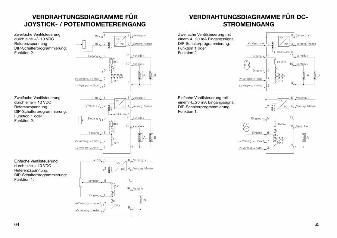
VERDRAHTUNGSDIAGRAMME FÜR DC-STROMEINGANG
Zweifache Ventilsteuerung mit einem 4...20 mA Eingangssignal.DIP-Schalterprogrammierung:Funktion 1 oderFunktion 2.
Einfache Ventilsteuerung mit einem 4...20 mA Eingangssignal.DIP-Schalterprogrammierung:Funktion 1.
65
VERDRAHTUNGSDIAGRAMME FÜRJOYSTICK- / POTENTIOMETEREINGANG
Zweifache Ventilsteuerung durch eine +/- 10 VDC ReferenzspannungDIP-Schalterprogrammierung:Funktion 2.
Zweifache Ventilsteuerung durch eine + 10 VDC Referenzspannung.DIP-Schalterprogrammierung:Funktion 1 oderFunktion 2.
Einfache Ventilsteuerungdurch eine + 10 VDC Referenzspannung.DIP-Schalterprogrammierung:Funktion 1.
64

TECHNISCHE BESCHREIBUNG• Zwei Sicherheitsmaßnahmen sind eingelegen um Programmierung während des
Betriebs zu verhindern. Das korrekte Passwort (030) muss ins Menü [PAS] einge geben werden und der Ausgang muss kein Signal abgeben (das Display muss000 zeigen). Dies wird durch Ausschaltung der +UB auf der Klemme 3 gesichert.
• Die Einheit kann mit einem Joystick / Potentiometer oder einem Prozess-strom / Spannungssignal und einer internen Versorgung von +10 V und eventuell -10 V gesteuert werden. Wird das Prozesssignal benutzt, kann der Eingang als Differenzialverstärker angeschlossen werden (DP1 SW 6 off) und wirkt so einem Potentialfehler auf Grund einer unzweckmäßigen Erdung, entgegen. Bei einem Joystick / Potentiometereingang muss der Eingang als Einzelausgang geschaltet werden und es besteht die Möglichkeit, einen 10 kΩ Belastungs-widerstand mit einzuschalten (DP1 SW 5 on), sodass immer Strom im Gleitkontakt des Potentiometer fließt.
• Zur Umschaltung der A und B Ventile stehen zwei Funktionen zur Auswahl. Funktion 1: das A Ventil ist angewählt, wenn Klemme 2 mit +UB beaufschlagt wird. Funktion 2: die Umschaltung zwischen A/B Ventil erfolgt automatisch über den Wert des Eingangssignals (kein Signal an Klemme 2). Eingangs signal: 0...50% = Ventil A 100...0%. Eingangssignal: 50...100% = Ventil B 0...100%
• Beim Anschluss der Ventilspule ist es wichtig zu beachten, dass der Impulsstrom = VVersorg./R-Spule den zugelassenen Höchstwert von 7A nicht überschreitet.
• Um eine unbeabsichtigte Bedienung in Verbindung mit z.B. einer unpräzisen neutralen Stellung auf einem Joystick zu verhindern, besteht die Möglichkeit, ein Todband zu programmieren. Dieses Todband bewirkt, dass der Eingang über ein gewisses Niveau kommen muss, bevor der Ausgang reagiert.
• Es besteht die Möglichkeit die Vorspannung (Bias) einzustellen und zwar so,dass man Rücksicht auf die Wanderung des Ventilsitzes nimmt vor dem Öldurchfluss.
• Man hat auch die Möglichkeit zwei feste Maximalströme (IMax1 & IMax2) zu programmieren. Der Wechsel zwischen den beiden Strömen geschieht mit einem externen PNP-Signal auf der Klemme 7. Die Funktion kann unter ande-rem in Verbindung mit einem Endschalter angewandt werden und zwar so, dass der letzte Teil der Wanderung langsam geschieht.
• Die Ventilsteuerung erfüllt die EMC-Daten, sofern das Installationskabel der angeschlossenen Ventile abgeschirmt ist. Der Schirm wird an die Versorgungserde angeschlossen.
67
VERDRAHTUNGSDIAGRAMME FÜR DC-SPANNUNGSEINGANG
Zweifache Ventilsteuerung mit einem Eingangssignal von 0...1 VDC.DIP-Schalterprogrammierung:Funktion 1 oderFunktion 2.
Einfache Ventilsteuerung mit einem Eingangssignal von 0...1 VDC.DIP-Schalterprogrammierung:Funktion 1.
Zweifache Ventilsteuerung mit einem Eingangssignal von -10...+10 VDC.DIP-Schalterprogrammierung:Funktion 1 oderFunktion 2.
66
6968

0.0. Normalzustand - Das Display zeigt den Ausgangswert von IVentil in Prozent an.
Das Display geht in diesen Zustand beim Einschalten der Spannung, oder wenn keine Taste innerhalb einer Periode von 2 Minuten aktiviert worden ist.
VAL - Eintasten des Passwortes.
1.1 PAS - Programmierzutritt. Das akzeptierte Passwort gilt bis die Versorgungsspannung abgeschal-tet ist. Das Passwort ist 030
2.0 CUA - Einstellung der Ströme für Ventil A.
2.1 LOA - Rückstellung Ventil A.Der Wert wird in % im Verhältnis zu IVentil eingestellt.Zulässige Wahlmöglichkeiten 0...99.9%.
2.2 IA1 - Strombegrenzung Imax1.Der Wert wird in % im Verhältnis zu IVentil eingestellt.Zulässige Wahlmöglichkeiten 0...99.9%.
2.3 IA2 - Strombegrenzung Imax2.Der Wert wird in % im Verhältnis zu IVentil eingestellt.Zulässige Wahlmöglichkeiten 0...99.9%.
3.0 CUB - Einstellung des Stromes für Ventil B.
Wird auf die gleiche Weise wie Ventil A eingestelt.
4.0 RAN - Einstellung der Rampenparameter.
4.1 ON - Wahl der Rampe on/off.1 = Rampe aktiv, 0 = Rampe inaktiv.Zulässige Wahlmöglichkeiten 0 oder 1.
4.2 UP - Einstellung der Rampenzeit aufwärts.Wird in Sekunden eingestellt.Zulässige Wahlmöglichkeiten 0...10 s.
4.3 DO - Einstellung der Rampenzeit abwärts.Wird in Sekunden eingestellt.Zulässige Wahlmöglichkeiten 0...10 s.
71
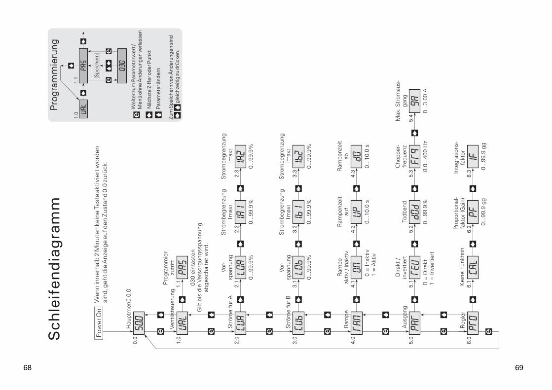
PROGRAMMIERUNG / BEDIENUNGDER DRUCKTASTEN
DOKUMENTATION ZUM SCHLEIFENDIAGRAMM
Allgemeines:
Die Programmierung ist menügesteuert. Die Hauptmenüs sind nummeriert im Niveau 0 (X.0), und die Untermenüs im Niveau 1 (X.1..X.4). Unter jedem Untermenü befindet sich ein Eintastmenü. Der Aufbau ist so ausgeführt, dass die Menüs die am meisten angewandt werden, am nächsten dem Normalzustand Menü 0.0 liegen. Bitte beachten Sie, dass die Program-mierung nur möglich ist, wenn das Untermenü 1.1 PAS den Wert 030 hat. Die Änderungen werden erst nach Rückkehr zum Menüpunkt 0.0 im EEprom gespeichert.
Man findet rund in den Haupt- Unter- und Eintastmenüs mit Hilfe von 3 Drucktasten und zwar 3 , 1 und 2,
Das Schleifendiagramm zeigt die Funktion der Drucktasten an.
Beim Drücken auf 2 wechselt das Untermenü zu dem Eintastmenü und gibt den aktuellen Wert an.
In den Eintastmenüs blinken die Ziffern die geändert werden können.
Eine aktive Zifferposition wird mit der Taste
3 verschoben und mit der Taste 1 geän-dert.
Wenn das Komma blinkt, kann die Plazierung mit der Taste 1 geändert werden.
Bei Eintastmenüs mit festen Parametern, wird zwischen den Parametern mit der Taste 1 gewechselt.
Um Änderungen vorläufig zu specihern sind 31 gleichzeitig zu aktivieren. Um Ânderungen permanent zu speichern wechseln Sie zum Menü 0.0.
Verlassen der Einstellung ohne zu speichern geschieht durch das Drücken auf die Taste 2.
70

5.0 PAR - Parametereinstellung für den Ausgang.
5.1 REV - Wahl von direktem / invertiertem Ausgang.0 = direkt, 1 = invertiert.Zulässige Wahlmöglichkeiten 0 oder 1.
5.2 DOD -Einstellung des Todbandes für z.B. den Joystick.Die Einstellung geschieht in % vom Eingangsbereich.Zulässige Wahlmöglichkeiten 0...99,9%.
5.3 FRQ - Einstellung der Chopperfrequenz für den Ausgangsstrom.Wird in Hz eingestellt. Zulässige Wahlmöglichkeiten 8...400 Hz.
5.4 GA - Einstellung von IVentil.Die Einstellung geschieht in Ampère - mit 2 Dezimalen. Zulässige Wahlmöglichkeiten 0...3,00 A.
6.0 PRO - Produktion.
OBS - Die Werte müssen nicht geändert werden!Das Hauptmenü mit den Untermenüs das PR electronics A/S zum Aufsetzen und Kalibrieren von 2224 anwendet.
72

PR electronics A/S tilbyder et bredt program af analoge og digi-tale signalbehandlingsmoduler til industriel automation. Vores kompetenceområder omfatter: Isolation, Displays, Ex-barrierer, Temperatur samt Universal-moduler. Alle produkter opfylder de strengeste internationale standarder, og størstedelen integrerer den patenterede STREAM-SHIELD teknologi, der sikrer driftsik-kerhed i selv de værste omgivelser. Vores motto »Signals the Best« er indbegrebet af denne fi losofi – og din garanti for kvalitet.
PR electronics A/S offers a wide range of analogue and digital signal conditioning modules for industrial automation. Our areas of competence include: Isolation, Displays, Ex barriers, Tem-perature, and Universal Modules. All products comply with the most exacting international standards and the majority feature our patented STREAM-SHIELD technology ensuring reliability in even the worst of conditions. »Signals the Best« is the epitome of our philosophy – and your guarantee for quality.
PR electronics A/S offre une large gamme de produits pour le traite ment des signaux analogiques et numériques dans tous lesdomaines industriels. Nos compétences s’étendent des transmet-teurs de température aux affi cheurs, des isolateurs aux barrières SI, jusqu’aux modules universels. Tous nos produits sont conformes aux normes internationales les plus strictes et la majorité d’entre eux répondent même à la technologie brevetée STREAM-SHEILD qui garantie un fonctionnement fi able sous les conditions les plus défavorables. Notre devise »SIGNALS the BEST« c’est notre ligne de conduite - et pour vous l’assurance de la meilleure qualité.
PR electronics A/S verfügt über ein breites Produktprogramm an analogen und digitalen Signalverarbeitungsmodule für die indu-strielle Automatisierung. Unsere Kompetenzbereiche umfassen: Displays, Temperaturtransmitter, Ex- und galvanische Signal-trenner, und Universalgeräte. Alle Produkte von PR electronics werden in Überein stimmung mit den strengsten internationalen Normen produziert. Für die Mehrzahl aller Produkte garantiert die patentierte STREAM-SHIELD Technologie höchste Zuverläs-sigkeit auch unter schwierigsten Einsatzbedingungen. »Signals the Best« ist Ihre Garantie für Qualität!
DK
UK
FR
DE
SubsidiariesFrancePR electronics SarlZac du Chêne, Activillage2, allée des Sorbiers,F-69500 Bron
GermanyPR electronics GmbHBamlerstraße 92D-45141 Essen
ItalyPR electronics S.r.l.Via Giulietti, 8IT-20132 Milano
SpainPR electronics S.L.Avda. Meridiana 354, 6°-AE-08027 Barcelona
SwedenPR electronics ABAugust Barks gata 6AS-421 32 Västra Frölunda
UKPR electronics LtdFairlie Quay Enterprise ParkMain Road, FairlieAyrshire, KA29 0AS
USAPR electronics Inc16776 Bernardo Center DriveSuite 203San Diego, California 92128
[email protected]. +33 (0) 4 72 14 06 07fax +33 (0) 4 72 37 88 20
[email protected]. +49 (0) 201 860 6660fax +49 (0) 201 860 6666
[email protected]. +39 02 2630 6259fax +39 02 2630 6283
[email protected]. +34 93 311 01 67fax +34 93 311 08 17
[email protected]. +46 (0) 3149 9990fax +46 (0) 3149 1590
[email protected]. +44 (0) 1475 568 000fax +44 (0) 1475 568 222
[email protected]. +1 858 521 0167fax +1 858 521 0945
Head offi ce
Denmark www.prelectronics.comPR electronics A/S [email protected] 10 tel. +45 86 37 26 77DK-8410 Rønde fax +45 86 37 30 85