dk-s124 simple tone generator - application project...application note r12an0051eu0104 rev.1.04 page...
TRANSCRIPT
Application Note
R12AN0051EU0104 Rev.1.04 Page 1 of 23 Feb 9, 2018
Renesas Synergy™ Platform
DK-S124 Simple Tone Generator Introduction This simple tone generator example dynamically generates the data necessary to represent one full cycle of a sine wave. It uses that data to generate an audio tone by repetitively driving the on-board Digital-to-Analog converter (DAC) of the DK-S124 Synergy™ MCU, that in turn drives the amplifier connected to the earphone jack. The frequency of the sine wave is varied by changing the sample rate used to output the data.
While the DK-S124 Synergy MCU comes with the PMOD LCD display shown in Figure 1. This program uses a simple two-button interface for control and the on-board LEDs for operator feedback. The PMOD LCD is not used in this example application.
Required Resources The example application targets the DK-S124 Synergy MCU Group. To build and run the application, you will need:
• DK-S124 kit v3.0 or later • PC running Microsoft® Windows® 7 or later with the following Renesas software installed:
e2 studio ISDE v6.2.0 or newer Synergy Software Package (SSP) v1.3.0 or later IAR Embedded Workbench® for Renesas Synergy™ v8.21.1 Synergy Standalone Configurator (SSC) v6.2.0.
You can download the required Renesas software from the Renesas Synergy™ Gallery: https://synergygallery.renesas.com
Prerequisites You should have some experience with either the Renesas Synergy e2 studio ISDE or the IAR Embedded Workbench® for Renesas Synergy™ ISDE. This program may be compiled and run using either tool chain.
You should also be familiar with the Synergy Software Package (SSP). Before you perform the procedures in this application note, you may want to follow the procedure referenced in your board’s Quick Start Guide to build and run the Blinky project. By doing so, you will become familiar with building and running the SSP applications while ensuring that the debug connection to your board is functioning properly.
Time Required You should be able to install, build, and run the example application in under 30 minutes. The high-level steps involved are:
1. Configure the DK-S124 Synergy MCU to run the tone generator example application.
2. Import, build, and debug the project.
3. Play audio tones through the earphone jack or an external speaker.
4. Cycle through a predefined list of audio tones using the momentary push button S1.
5. Enable/disable the audio output using the momentary push button S2.
6. Vary the volume using POT1.
R12AN0051EU0104 Rev.1.04
Feb 9, 2018

Renesas Synergy™ Platform DK-S124 Simple Tone Generator
R12AN0051EU0104 Rev.1.04 Page 2 of 23 Feb 9, 2018
Contents
1. Overview and Design Considerations ...................................................................................... 3
2. Synergy Platform Capabilities .................................................................................................. 3
3. Design Overview ..................................................................................................................... 5 3.1 Debouncing Switch Input ......................................................................................................................... 5 3.2 Accelerator Initialization .......................................................................................................................... 8 3.3 Threads ................................................................................................................................................... 8 3.4 Audio Thread Logic ................................................................................................................................. 9 3.5 Threads and Modules ............................................................................................................................ 10 3.6 Using the Periodic ADC Framework ...................................................................................................... 11 3.7 Configuring the ADC Unit ...................................................................................................................... 13 3.7.1 Callback for ADC Periodic Framework ................................................................................................ 14 3.8 Source Code Layout .............................................................................................................................. 14
4. Design Demonstration ........................................................................................................... 15 4.1 Configure the DK-S124 for the Tone Generator Example .................................................................... 15 4.2 Interacting with the Test Generator Example Program ......................................................................... 17
5. Importing and Building the Project ......................................................................................... 17
6. e2 studio Tricks - Examining Variables ................................................................................... 17 6.1 Visual Expressions ................................................................................................................................ 20
7. Next Steps ............................................................................................................................. 21

Renesas Synergy™ Platform DK-S124 Simple Tone Generator
R12AN0051EU0104 Rev.1.04 Page 3 of 23 Feb 9, 2018
Figure 1 DK-S124 with included PMOD LCD attached
1. Overview and Design Considerations The main goal of this application is to generate a pure audio tone, which could be used to examine the fidelity of the amplifier circuit connected to the earphone jack. The application builds the data points that are necessary to represent one cycle of a sine wave, and stores the data in a buffer. That data is then used to repeatedly drive the 12 bit Digital-to-Analog Converter connected to the amplifier that drives the earphone jack.
One of the design challenges in this application is to playback this sine wave data at varying frequencies. This is accomplished by one of the timer API calls that changes the period of the timer each time the momentary button S1 is pressed.
Another design challenge is to use the on-board potentiometer (POT1) to vary the volume of the tone being output by the application. The application must periodically read the analog voltage present at POT1 and adjust the output volume accordingly. Some ways to achieve this are:
1. Manually perform a single scan of data each time the main thread loop executes. 2. Use the periodic ADC framework and a callback function to scan the analog channel at a rate determined by a timer
module dedicated to the ADC scan. This application uses the second approach. Other example applications like the Thermostat application use the first method.
2. Synergy Platform Capabilities This application primarily deals with writing data to the on-board Digital-to-Analog Converter, that drives the earphone amplifier (U9). The playback is performed at a controlled rate, using the General Purpose Timer module. This controlled rate determines the frequency of the tone being generated. The SSP provides both higher level framework modules as well as the lower level driver modules to interface with these types of hardware peripherals without the need to write any low level driver code.
The following figure, highlights the S1 hardware peripherals used by the tone generator example application.

Renesas Synergy™ Platform DK-S124 Simple Tone Generator
R12AN0051EU0104 Rev.1.04 Page 4 of 23 Feb 9, 2018
Figure 2 S1 peripherals used by the tone generator example The following table, defines the processor pin connections used to connect the peripherals used in this example to the various external components on the DK-S124 Synergy MCU board. For additional information, you may also refer to the DK-S124 Synergy MCU Group schematics.

Renesas Synergy™ Platform DK-S124 Simple Tone Generator
R12AN0051EU0104 Rev.1.04 Page 5 of 23 Feb 9, 2018
Table 1 Port summary of peripheral connections used by the Tone Generator
Schematic part Description S1 port connection Pin function S1 Momentary switch Port 2 pin 6 I/O port pin S2 Momentary switch Port 0 pin 4 I/O port pin POT1 10K potentiometer Port 0 pin 12 Analog channel 7 U13 BMA250 3-axis Accelerometer Port 2 pin 6 IRQ U13 BMA250 3-axis Accelerometer Port 4 pin 1 SDA0 (I2C clock) U13 BMA250 3-axis Accelerometer Port 0 pin 0 SCL0 (I2C data) U11 Audio power amplifier Port 0 pin 14 DAC output
3. Design Overview The DK-S124 Synergy MCU Group board contains two momentary switches S1 and S2, and a potentiometer (POT1) that can be used for operator input. While the PMOD LCD display is not used, the DK-S124 Synergy MCU has three LEDs that can be used for operator feedback. The board also contains an earphone jack, that accepts the standard 3.5 mm connector found on typical earbuds. The following figure shows a simple block diagram of how inputs and outputs are connected to the S124 MCU.
Figure 3 Simple block diagram showing hardware connections The Tone Generator example application has a single operation mode. The two push buttons on the DK-S124, S1 and S2, control the application. Only one of the three on-board LEDs are used for operator feedback. For more details on the operator interface, see section 4, Design Demonstration.
3.1 Debouncing switch input One of the challenges always present when dealing with the switch input is the switch bounce. Most mechanical switches have what is known as contact bounce. This is a period of time when the state of the switch bounces from one state to the next, after being pressed. To avoid false triggers, these false transitions must be ignored by either the hardware or the firmware. A typical firmware technique is to sample the switch state at regular intervals, waiting for the switch state to remain constant for a pre-determined number of samples, before considering it a valid state.
Both the pushbuttons on the DK-S124 Synergy MCU Group are connected to hardware pins with interrupt capability. Some applications such as the Simple Record application poll these pins using the g_ioport driver. This driver is typically added to your application automatically in the HAL/Common area before any user defined threads. This application highlights the use of the Synergy External IRQ driver (r_icu) to simultaneously detect button presses and filter out the switch bounce.
In the following figure, shows the delayed sweep of an oscilloscope trace being used to examine the contact bounce on S2. The oscilloscope is set to a single capture mode, triggering on a falling edge. The top trace is 200 ms per division, and multiple button presses are captured. The bottom trace uses the delayed sweep (zoom) mode to expand one of the edges where contact bounce exists. As seen in the following figure, switch only bounced once and the bounce is of short duration. The board mounted momentary switches used on the DK-S124 have minimal bounce, and this necessitated many samples to

Renesas Synergy™ Platform DK-S124 Simple Tone Generator
R12AN0051EU0104 Rev.1.04 Page 6 of 23 Feb 9, 2018
be taken before capturing the bounce shown in the below figure. Many mechanical switches have a bounce that is much worse, and no longer a debounce period is needed.
Figure 4 Contact bounce on S2 The external interrupt pins on the S124 MCU provides digital filtering that eliminates the need to debounce inputs in firmware. You can configure this filtering using two properties in r_icu stack as highlighted in the following figure. The digital filter samples the input signal and ignores any signal with a pulse width less than three sample cycles. The sample cycle is based on the current setting of PCLKB divided by the value set in the Properties tab, which in this case is 64.

Renesas Synergy™ Platform DK-S124 Simple Tone Generator
R12AN0051EU0104 Rev.1.04 Page 7 of 23 Feb 9, 2018
Figure 5 Digital filtering properties for r_icu driver The value of PCLKB may be set using the Clocks tab in the Synergy configurator. As seen in the following figure, PCLKB for the Tone Generator Application is set to the high-speed oscillator (HOCO) divided by 2, for a frequency of 24 MHz. Dividing this 24 MHz frequency by 64 yields a digital filter frequency of 375 kHz, which means that the sampling period is 1/375,000 or 2.66 µs. Three of these sampling periods are just under 8 µs. This means that any pulse width less than 8 µs is ignored by the digital filter.
Figure 6 Clock tree as displayed in the Clocks tab for the Tone Generator example As mentioned previously, the switches used on the DK-S124 board have minimal bounce and so this value of 10 µs for the digital filtering works well for the tone generator application. However, it is quite possible that you will encounter switches with longer bounce times. In this case, you would need to increase the digital filter time to avoid false triggers.
Since the maximum divide ratio you can set in the digital filter properties (Figure 5) is 64, you would need to increase the divide ratio of PCLKB in the Clocks tab, thereby lowering the frequency of PCKLB. For example, you could increase the divide ratio to PCLKB Div/4 to double the effective debounce time provided by the digital filtering, or quadruple it by increasing the divide ratio to PCLKB Div/8 for a total of ~32µs of debounce time.

Renesas Synergy™ Platform DK-S124 Simple Tone Generator
R12AN0051EU0104 Rev.1.04 Page 8 of 23 Feb 9, 2018
Note: When increasing the digital filtering time by reducing the PCLKB frequency, keep in mind that PCLKB is also used for other peripherals on the S124 MCU (such as the SCI, IIC, SPI). Section 8 of the SSP User’s Manual describes the S124 MCU clocks, and lists all the peripherals that are driven by PCLKB. You may find that a throughput reduction in other peripherals, resulting from a slower PCLKB frequency, may adversely affect your application. In such a case, you would need to leave PCLKB set to a higher frequency and either replace or augment the digital filtering with a firmware debounce scheme.
3.2 Accelerator Initialization On the DK-S124 Synergy MCU v2.0, the accelerometer IRQ line is shared with S1, seen in the following figure.
Figure 7 S1 input shared with accelerometer IRQ line The accelerometer IRQ pin defaults to a push/pull configuration and active high IRQ state. This means that it is always pulling down on the line connected to S1, which prevents the use of this line for reading the state of S1. To use S1, you must change the interrupt configuration of the accelerometer. To do this, the I2C framework is added to the audio thread, and several I2C commands are issued to the accelerometer during the audio thread initialization sequence.
3.3 Threads For simplicity, this application is designed with a single thread, as summarized in the table below.
Table 2 Application thread names and functions
Thread name Thread function Audio thread Handles all logic associated with the tone generator
In the following figure is a conceptual diagram of the Tone Generator example application. Peripherals internal to the S124 MCU are highlighted in blue, and external peripherals (such as the accelerometer) are highlighted in gray. The component used to access each peripheral is shown in text on the connecting line.

Renesas Synergy™ Platform DK-S124 Simple Tone Generator
R12AN0051EU0104 Rev.1.04 Page 9 of 23 Feb 9, 2018
Figure 8 Conceptual diagram of the Tone Generator application
3.4 Audio thread logic The code in the audio thread, or other threads, can be divided into three separate sections:
• Any initialization code that executes prior to entering the main thread loop • Code that executes each time the main thread loop executes • Code that executes inside callback routines, which are executed in response to an interrupt The tone generator example application is special because the only code that actually executes in the main thread loop is the tx_thread_sleep(). This is the call that suspends the thread execution allowing other threads to run.
The audio thread contains four callback routines that do all the work:
• A separate callback routine for each switch (S1 and S2) • A callback routine for the ADC period framework that samples analog data from the on-board potentiometer (POT1) at
regular intervals, and then uses this data to determine the output volume • Another callback routine associated with the General Purpose Timer (GPT) interrupt, is used to play back the sine wave
data at a set rate. This rate determines the frequency of the tone you hear. The rate changes in response to one of the switch interrupts, to rotate through all the pre-defined frequencies.
In the following figure it shows the logic implemented in the main thread loop. To be responsive, the audio thread samples the button states every 50 ns. Normal button presses of S1 and S2 result in a few variables (for example, cur_freq or amp_enable) being set. These variables are examined inside the other callback routines if necessary.

Renesas Synergy™ Platform DK-S124 Simple Tone Generator
R12AN0051EU0104 Rev.1.04 Page 10 of 23 Feb 9, 2018
Figure 9 Simplified flowchart of the inputs thread logic
3.5 Threads and modules As is the case with all Renesas Synergy™ Platform applications, module drivers are added to threads and their properties are configured using the e2 studio ISDE Configurator. The configurator is opened by double clicking on the configuration.xml file from inside the project explorer in e2 studio. For more information on Synergy modules and drivers, refer to the SSP User’s Manual.
To configure interfaces to external peripherals, you must understand how a peripheral is connected to the S124 MCU. As mentioned previously, for example, it is necessary to initialize the accelerometer to free up S1 for our use. The S124 MCU communicates with accelerometer over an I2C bus. It is therefore necessary to add an I2C driver to the thread that communicates with the accelerometer. As shown in the following figure, the r_riic driver has been added.
Figure 10 Audio thread stacks The Synergy MCU Group contains two different peripherals for I2C communication, a dedicated I2C peripheral, and the Serial Communications Interface (SCI), that may act as either a simple I2C, simple SPI, or UART (Synchronous or Asynchronous). The SSP supports both types of I2C peripherals. The same scenario is true for SPI peripherals.
Choosing which peripheral to use depends on the complexities of your system. In many cases, you may not need all the power available on the dedicated SPI or I2C peripherals. You may need to use the pins assigned to the dedicated I2C

Renesas Synergy™ Platform DK-S124 Simple Tone Generator
R12AN0051EU0104 Rev.1.04 Page 11 of 23 Feb 9, 2018
peripheral for another use. The decision on which peripheral to use must typically be made during the hardware design phase since it affects which physical processor pins are connected to the peripheral.
One consideration to make when designing the system are the types of peripherals your design requires and how many of each type will be needed. While the S124 MCU only has two dedicated SPI and I2C peripherals, it has nine SCI peripherals which can be configured as either simple SPI or I2C.
The reason that the Tone Generator application uses the dedicated I2C peripheral, rather than one of the nine SCI peripherals, is simply because these are the pins that the hardware designers chose to connect the S124 MCU to the accelerometer.
3.6 Using the Periodic ADC Framework The Tone Generator application uses the ADC Periodic Framework component to sample the analog value present on the potentiometer (POT1). The value read is then scaled appropriately and used to set one of four volume levels as you rotate the potentiometer. The ADC Periodic Framework component provides the ability to sample analog data at a prescribed rate. You define a callback function to process the data each time a new sample is complete.
The ADC periodic framework can be a bit confusing to get working. If you already have experience using this framework component, you can skip ahead to the next section. If not, study this section carefully and review the application code for the callback function associated with it to understand how to configure and handle scan data in the callback.
Note: One of the key strengths of the Periodic ADC Framework component is the ability to sample multiple analog channels. You can even configure the ADC Periodic Framework component to take multiple samples of each channel during each iteration. This application note does not explore that functionality but other application notes such as the Simple Record Example use additional features of the Periodic ADC Framework.
The ADC Periodic Framework component, in the following figure is essentially a framework layer built on top of the r_adc ADC driver, a r_gpt timer driver, and the r_dtc transfer driver. You need to configure a few parameters in each of these components except for the transfer driver (r_dtc), whose role is completely transparent to the user.
Figure 11 ADC Periodic Framework Stack As is the case with configuring all SSP components, you click on the appropriate box and then define the properties using the Properties tab. The ADC Periodic Framework component contains numerous properties and the default values are acceptable for many of them. Once you have imported and built the application, as outlined in section 4, Design Demonstration, you can browse all the properties for each of the components used in the applications. A few of the properties are reviewed in this section.
As you can see in the following figure, the buffer g_user_buffer that holds the samples is 16 bytes deep. A single sample is taken at each scan iteration and the GPT timer channel 0 is used to trigger the scan. The callback name is g_adc_framework_user_callback. You may choose any name for the callback function if the callback function in your code matches the name you define here.

Renesas Synergy™ Platform DK-S124 Simple Tone Generator
R12AN0051EU0104 Rev.1.04 Page 12 of 23 Feb 9, 2018
Figure 12 Properties for sf_adc_periodic The data-buffer (g_user_buffer) used to store the samples will be defined for you in the auto-generated audio_thread.c file. We will reference this buffer in the callback routine to read the data associated with each scan. An important consideration here is the GPT channel selection. In this case, we must use channel 0 since the channel used by the GPT timer module is locked at channel 0, shown in the following figure.
The key parameters for the r_rgpt module are outlined in the following figure. You must enable and pick a priority for the GPT0 COUNTER OVERFLOW IRQ (interrupt) for the scan to work. Additionally, the sample rate of 50 ms is defined by setting the Period Value to 50 and the Period Unit to Milliseconds. This means that the ADC framework samples the analog value present on the potentiometer and call the callback function we defined in the sf_adc_periodic component every 50 ms.
Figure 13 r_rgpt properties for ADC Periodic Framework Note: You can select from a large range for the Period Unit based on the specific needs of your application. The options
currently include Raw Count, Nanoseconds, Microseconds, Milliseconds, Seconds, Hertz, and Kilohertz.

Renesas Synergy™ Platform DK-S124 Simple Tone Generator
R12AN0051EU0104 Rev.1.04 Page 13 of 23 Feb 9, 2018
3.7 Configuring the ADC Unit The component with the largest number of properties is the r_adc component, which is used to configure the ADC unit. Most of the default values are acceptable. Since no changes to the lower half of the properties are necessary, the focus is only on the highlighted properties shown in the following figure. As with many SSP components, you must enable the IRQ associated with it. Here, the ADC0 SCAN END interrupt is set to Priority 1. This interrupt priority could be lower since the analog sampling in this application is only used to set the volume control. In other applications, such as the Simple Record example, audio data is being sampled in real time so a higher priority interrupt id is justified.
As is the case with many SSP components, you may optionally assign your own name to the component. That name would then be used in the various API calls used to access the component inside your code. Here, the default name of g_adc0 is used. A name such as g_adc_volume_control could have been easily selected to make the code more readable. Many of these decisions will either be based on personal preference or your coding standards used.
Figure 14 Properties for r_adc component of ADC periodic framework One of the most important properties that needs to be set correctly in the r_adc component is Resolution. At the time writing this application note, the default for this field is 8 bit (S7G2 MCU only), that will not work for the S124 MCU as seen in the following figure. Note: If you are working on an S124 MCU and forget to select either 12 bit or 14 bit (S3A7/S124 MCU only), you will
receive an invalid parameter error at run time, which can be a bit confusing to track down at run time.

Renesas Synergy™ Platform DK-S124 Simple Tone Generator
R12AN0051EU0104 Rev.1.04 Page 14 of 23 Feb 9, 2018
Figure 15 ADC resolution defaults to 8 bit (S7G2 MCU only) The actual channels to be sampled each time an ADC scan occurs need to be configured. You can see that only channel 7 has been selected, which is the analog channel connected to the potentiometer. Other application notes, such as the Simple Record example show how to sample multiple channels, for example, the potentiometer and the microphone input at the same time.
3.7.1 Callback for ADC Periodic Framework Once you have defined all the properties and built your code, you will see a section of code like that shown below in the audio_thread.h file:
/** Buffer where the sampled data will be stored for application usage */ extern uint16_t g_user_buffer[16]; #ifdef g_adc_framework_user_callback #define ADC_PERIODIC_ON_ADC_PERIODIC_CALLBACK_USED_g_sf_adc_periodic0 (0) #else #define ADC_PERIODIC_ON_ADC_PERIODIC_CALLBACK_USED_g_sf_adc_periodic0 (1) #endif #if ADC_PERIODIC_ON_ADC_PERIODIC_CALLBACK_USED_g_sf_adc_periodic0 /** Declaration of user callback function. This function MUST be defined in the user application.*/ void g_adc_framework_user_callback(sf_adc_periodic_callback_args_t * p_args); #endif This code defines the function prototype of the call back for you. It also says this code must be defined in your application. You will find the code for g_adc_framework_user_callback() at the bottom of the audio_thread_entry.c file. The flowchart in Figure 9, highlights the functionality of each callback routine.
3.8 Source Code Layout This section gives a brief overview of the source code layout that you would expect to see when you build the Tone Generator project with e2 studio. If you are already experienced writing Synergy applications, you are probably familiar with how e2 studio organizes a standard project, and can skip ahead to the next section.
After you have imported the Tone Generator application into the e2 studio and built the project, you should see a directory structure like the one shown in the following figure. The first time you import the project, you may notice that the synergy_gen, synergy, debug, synergy and synergy_cfg folders do not exist. These folders are built automatically by the framework when you compile the project. To reduce size, these subfolders are normally not included when applications are distributed.
The only files you typically need to work with (for example, add/delete code) in your project are the files highlighted in green.

Renesas Synergy™ Platform DK-S124 Simple Tone Generator
R12AN0051EU0104 Rev.1.04 Page 15 of 23 Feb 9, 2018
Figure 16 Source code layout for DK-S124 OOB v1.0 program
4. Design Demonstration The DK-S124 Synergy MCU Group comes preloaded with the Out-of-Box application software, that displays the values of the various analog sensors on the PMOD LCD screen. Prior to running the tone generator example code, you need to reprogram the board with the Tone Generator firmware. Before doing this, you should first configure the board shown in the following section.
4.1 Configure the DK-S124 for the Tone Generator Example The steps to configure the DK-S124 Synergy MCU Group are:
1. Verify that all headers near the battery are configured with all jumpers to make connections as shown in the top portion of the following figure.
2. Connect the JLink®-OB on J18 of the DK-S124 MCU to the PC using a micro USB cable, as shown in the bottom portion of the following figure.
3. Connect speakers or headphones to J16 using a 3.5 mm jack plug as shown in Figure 18 following.

Renesas Synergy™ Platform DK-S124 Simple Tone Generator
R12AN0051EU0104 Rev.1.04 Page 16 of 23 Feb 9, 2018
Figure 17 Power setup (top) and J-Link OB connection (bottom)
Figure 18 Connecting headphones or external speaker Now that you have configured the board, you need to import the Tone Generator application into e2 studio, compile it, and load it onto your DK-S124 board.
On power up, the Tone Generator program defaults to outputting a tone and playing the first tone in its list of pre-defined frequencies. The following section describes how to interact with the program.
Renesas Synergy™ Platform DK-S124 Simple Tone Generator
R12AN0051EU0104 Rev.1.04 Page 17 of 23 Feb 9, 2018
4.2 Interacting with the Test Generator Example Program The steps to interact with the Test Generator program are:
1. S1 enables/disables the output. When enabled, the red LED (LED1) lights up, and the tone generator outputs the currently selected frequency. When disabled, the red LED turns off and no sound is passed to the earphone jack. On power up, the program defaults to the output being enabled.
2. S2 increments through the list of frequencies that the tone generator is programmed to play if the output is enabled. If the output is disabled (using S1) S2 has no effect.
3. POT1 acts as a volume control, where rotating clockwise increases the volume. CAUTION: Listening to excessive volume levels can damage your hearing.
5. Importing and Building the Project Follow the procedure in the SSP Import Guide (r11an0023eu0119-synergy-ssp-import-guide.pdf ) to import the project into the e2 studio ISDE, and to build and debug the project. For the debug configuration, select ToneGenerator Debug (under Renesas GDB Hardware Debugging).
6. e2 studio Tricks - Examining Variables When debugging your applications, you often need to examine the values of certain variables as you step through your code in the debugger. The e2 studio provides several ways to do this. Once you have compiled your project and loaded it onto your board, e2 studio asks you if you want to switch to the Debug view. The next few images assume you are in the Debug perspective.
You can change to the Debug perspective at any time by choosing Window > Perspective > Open Perspective > Other and then choosing the Debug perspective.
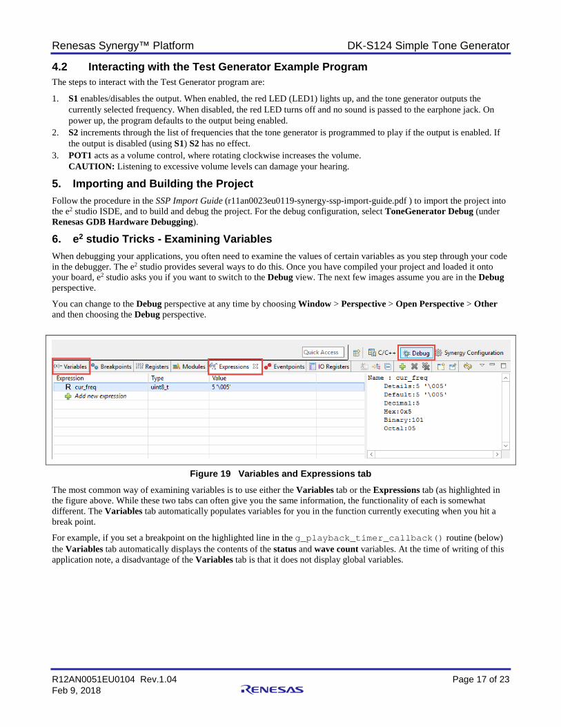
Figure 19 Variables and Expressions tab The most common way of examining variables is to use either the Variables tab or the Expressions tab (as highlighted in the figure above. While these two tabs can often give you the same information, the functionality of each is somewhat different. The Variables tab automatically populates variables for you in the function currently executing when you hit a break point.
For example, if you set a breakpoint on the highlighted line in the g_playback_timer_callback() routine (below) the Variables tab automatically displays the contents of the status and wave count variables. At the time of writing of this application note, a disadvantage of the Variables tab is that it does not display global variables.

Renesas Synergy™ Platform DK-S124 Simple Tone Generator
R12AN0051EU0104 Rev.1.04 Page 18 of 23 Feb 9, 2018
void g_playback_timer_callback(timer_callback_args_t * p_args) { SSP_PARAMETER_NOT_USED (p_args); ssp_err_t status; static uint16_t wave_count = 0;
/* If the output is enabled, write the current data point for the sine wave to the DAC */ if(amp_enable){ /* Write out the sine wave data */ status = g_playback_dac.p_api->write(g_playback_dac.p_ctrl, (dac_size_t)(sine[wave_count++] << volume_level)); APP_ERR_TRAP(status); if (wave_count >= SINE_POINTS) { wave_count = 0;} } } This is where the Expressions tab comes into play. The Expressions tab allows you to enter variable names or even expressions that use variable names. You are not restricted to only seeing the local variables of the function you are currently in. It does not populate its view automatically with the contents of any variables.
Figure 20 Variable tab automatically displays function variables To display a variable, you click on the green arrow next to the prompt that says Add New Expression and enter the name of your variable. This is illustrated in the following figure, by adding the variables, cur_freq, amp_enable and volume_level. The associated display shows columns for the Expression, Type, and Value of the expression. In this case, the expression is just the variable name. Clicking on any of the expressions shows you the differing views of the data (for example, hex or decimal) in the pane to the right of the Expressions tab.
Figure 21 Expressions tab displaying content of three variables Notice in the above figure, that the cur_freq variable has an upper case R just to the left of it. By default, the values of the expressions in the Expressions tab are only updated when you hit a break point. One of the benefits of the Expressions tab is the ability to display the contents of your variables in real time. There are several ways of accomplishing this. The first way is to click on the (x)= next to the variable you are interested in, while your application is running. This presents the dialog you see in the following figure, asking if you want to change this expression to be refreshed in real time.

Renesas Synergy™ Platform DK-S124 Simple Tone Generator
R12AN0051EU0104 Rev.1.04 Page 19 of 23 Feb 9, 2018
Figure 22 Dialog prompting to change to real-time refresh The second way is to right click on the variable and select Real-time refresh from the dropdown menu as shown in the following figure. You may also use this dropdown menu to disable real-time refresh, change the expression associated with the current item selected, delete the expression, and so on.
Once you have enabled real-time refresh on a specific expression, you do not need to hit a breakpoint and pause execution of your application to see the value of the variable.
Note: Some variables are easier to examine at run time compared to others. If you have a variable that changes too fast, it will be difficult to see all its values as it changes. In this case, it is better to set a break point to examine the variable value at specific points in your program execution.
Figure 23 Enabling real-time refresh

Renesas Synergy™ Platform DK-S124 Simple Tone Generator
R12AN0051EU0104 Rev.1.04 Page 20 of 23 Feb 9, 2018
6.1 Visual Expressions One final way of examining variables is using Visual Expressions. The e2 studio provides several graphical ways of representing your data. These are accessed through the Visual Expressions tab. If you do not see the Visual Expressions tab displayed, you may access it by selecting Window >Show View>Other and then selecting Visual Expressions under the Debug folder.
The following figure shows an example of the type of display that you can make inside the Visual Expressions tab.
Figure 24 Visual Expressions We will refer to these graphical representations of your data as widgets. You drag and drop a widget from Gauges, Controllers, or Indicators column in the left selection pane on to the canvas (right pane) and then configure their properties.
From left to right, we have three labels, the small square boxes, followed by a Gauge and a Thermometer. Right clicking on an item presents a dropdown list of operations that allows you to configure it as shown in the following figure.
Figure 25 Configuring the gauge To associate a visual expression with a variable, choose the Set expression option and simply type in the variable name or an expression.
Note: At the time of writing this application note, certain visual expressions such as the Gauge seem to only recognize float type values. To display integer variables, you must cast the value to a float before it is displayed.

Renesas Synergy™ Platform DK-S124 Simple Tone Generator
R12AN0051EU0104 Rev.1.04 Page 21 of 23 Feb 9, 2018
As shown in the figure below, label widgets have an additional option that allows you to choose the number format.
Figure 26 Choosing the number format of a Label widget
7. Next Steps After you run the example application, you can learn more about how the application works, and the API calls involved by examining the application source code.
Some experiments you might try are:
1. Explore the result of disabling the digital filtering on S1 (see section 4.1). With the digital filtering disabled, you may hear the frequency increase by more than one increment as you push S1. This is because the IRQ is responding to the switch bounce causing the IRQ callback (that increments the current frequency) to be called multiple times for a single switch press.
2. Increase/decrease the number of data points used to represent the sine wave. This can be done by changing the value of SINE_POINTS in audio_thread_entry.c and rebuilding the project. An increase in the number of points used to represent the sine wave results in a decrease in the frequency of the tone produced. A decrease in the number of points used to represent the sine wave results in an increase in the tone you hear.
If you have access to an oscilloscope, you can monitor the output of the DAC at P0_14, which is connected to pin 7 of the header J6 for easy access. Below are two different captures of ~1 kHz. The first capture uses more data points to represent the sine wave, and the second uses about half the data points.

Renesas Synergy™ Platform DK-S124 Simple Tone Generator
R12AN0051EU0104 Rev.1.04 Page 22 of 23 Feb 9, 2018
Figure 27 Effect of different number of data points Note: According to the Nyquist the orem, multiplying a given frequency by 2 gives the minimum number of data points
necessary to represent that frequency. In practice, many designers will want at least 4 to 10 data points. The more points sampled, the better the fidelity of the captured waveform.

Renesas Synergy™ Platform DK-S124 Simple Tone Generator
R12AN0051EU0104 Rev.1.04 Page 23 of 23 Feb 9, 2018
Website and Support Support: https://synergygallery.renesas.com/support
Technical Contact Details:
• America: https://www.renesas.com/en-us/support/contact.html • Europe: https://www.renesas.com/en-eu/support/contact.html • Japan: https://www.renesas.com/ja-jp/support/contact.html All trademarks and registered trademarks are the property of their respective owners.

Revision History
Rev. Date Description Page Summary
1.00 Aug 11, 2016 - Initial version 1.01 Feb 16, 2017 - Upgraded to SSP 1.2.0 1.02 Jul 06, 2017 - Upgraded to SSP 1.3.0 1.03 Sep 27, 2017 - Final edit to SSP 1.3.0 2 Required resources of SSP version changed 1.04 Feb 9, 2018 - Updated for SSP v1.4.0

http://www.renesas.comRefer to "http://www.renesas.com/" for the latest and detailed information.
Renesas Electronics America Inc.1001 Murphy Ranch Road, Milpitas, CA 95035, U.S.A.Tel: +1-408-432-8888, Fax: +1-408-434-5351Renesas Electronics Canada Limited9251 Yonge Street, Suite 8309 Richmond Hill, Ontario Canada L4C 9T3Tel: +1-905-237-2004Renesas Electronics Europe LimitedDukes Meadow, Millboard Road, Bourne End, Buckinghamshire, SL8 5FH, U.KTel: +44-1628-651-700, Fax: +44-1628-651-804Renesas Electronics Europe GmbHArcadiastrasse 10, 40472 Düsseldorf, GermanyTel: +49-211-6503-0, Fax: +49-211-6503-1327Renesas Electronics (China) Co., Ltd.Room 1709 Quantum Plaza, No.27 ZhichunLu, Haidian District, Beijing, 100191 P. R. ChinaTel: +86-10-8235-1155, Fax: +86-10-8235-7679Renesas Electronics (Shanghai) Co., Ltd.Unit 301, Tower A, Central Towers, 555 Langao Road, Putuo District, Shanghai, 200333 P. R. ChinaTel: +86-21-2226-0888, Fax: +86-21-2226-0999Renesas Electronics Hong Kong LimitedUnit 1601-1611, 16/F., Tower 2, Grand Century Place, 193 Prince Edward Road West, Mongkok, Kowloon, Hong KongTel: +852-2265-6688, Fax: +852 2886-9022Renesas Electronics Taiwan Co., Ltd.13F, No. 363, Fu Shing North Road, Taipei 10543, TaiwanTel: +886-2-8175-9600, Fax: +886 2-8175-9670Renesas Electronics Singapore Pte. Ltd.80 Bendemeer Road, Unit #06-02 Hyflux Innovation Centre, Singapore 339949Tel: +65-6213-0200, Fax: +65-6213-0300Renesas Electronics Malaysia Sdn.Bhd.Unit 1207, Block B, Menara Amcorp, Amcorp Trade Centre, No. 18, Jln Persiaran Barat, 46050 Petaling Jaya, Selangor Darul Ehsan, MalaysiaTel: +60-3-7955-9390, Fax: +60-3-7955-9510Renesas Electronics India Pvt. Ltd.No.777C, 100 Feet Road, HAL 2nd Stage, Indiranagar, Bangalore 560 038, IndiaTel: +91-80-67208700, Fax: +91-80-67208777Renesas Electronics Korea Co., Ltd.17F, KAMCO Yangjae Tower, 262, Gangnam-daero, Gangnam-gu, Seoul, 06265 KoreaTel: +82-2-558-3737, Fax: +82-2-558-5338
SALES OFFICES
© 2018 Renesas Electronics Corporation. All rights reserved.Colophon 7.0
(Rev.4.0-1 November 2017)
Notice1. Descriptions of circuits, software and other related information in this document are provided only to illustrate the operation of semiconductor products and application examples. You are fully responsible for
the incorporation or any other use of the circuits, software, and information in the design of your product or system. Renesas Electronics disclaims any and all liability for any losses and damages incurred by
you or third parties arising from the use of these circuits, software, or information.
2. Renesas Electronics hereby expressly disclaims any warranties against and liability for infringement or any other claims involving patents, copyrights, or other intellectual property rights of third parties, by or
arising from the use of Renesas Electronics products or technical information described in this document, including but not limited to, the product data, drawings, charts, programs, algorithms, and application
examples.
3. No license, express, implied or otherwise, is granted hereby under any patents, copyrights or other intellectual property rights of Renesas Electronics or others.
4. You shall not alter, modify, copy, or reverse engineer any Renesas Electronics product, whether in whole or in part. Renesas Electronics disclaims any and all liability for any losses or damages incurred by
you or third parties arising from such alteration, modification, copying or reverse engineering.
5. Renesas Electronics products are classified according to the following two quality grades: “Standard” and “High Quality”. The intended applications for each Renesas Electronics product depends on the
product’s quality grade, as indicated below.
"Standard": Computers; office equipment; communications equipment; test and measurement equipment; audio and visual equipment; home electronic appliances; machine tools; personal electronic
equipment; industrial robots; etc.
"High Quality": Transportation equipment (automobiles, trains, ships, etc.); traffic control (traffic lights); large-scale communication equipment; key financial terminal systems; safety control equipment; etc.
Unless expressly designated as a high reliability product or a product for harsh environments in a Renesas Electronics data sheet or other Renesas Electronics document, Renesas Electronics products are
not intended or authorized for use in products or systems that may pose a direct threat to human life or bodily injury (artificial life support devices or systems; surgical implantations; etc.), or may cause
serious property damage (space system; undersea repeaters; nuclear power control systems; aircraft control systems; key plant systems; military equipment; etc.). Renesas Electronics disclaims any and all
liability for any damages or losses incurred by you or any third parties arising from the use of any Renesas Electronics product that is inconsistent with any Renesas Electronics data sheet, user’s manual or
other Renesas Electronics document.
6. When using Renesas Electronics products, refer to the latest product information (data sheets, user’s manuals, application notes, “General Notes for Handling and Using Semiconductor Devices” in the
reliability handbook, etc.), and ensure that usage conditions are within the ranges specified by Renesas Electronics with respect to maximum ratings, operating power supply voltage range, heat dissipation
characteristics, installation, etc. Renesas Electronics disclaims any and all liability for any malfunctions, failure or accident arising out of the use of Renesas Electronics products outside of such specified
ranges.
7. Although Renesas Electronics endeavors to improve the quality and reliability of Renesas Electronics products, semiconductor products have specific characteristics, such as the occurrence of failure at a
certain rate and malfunctions under certain use conditions. Unless designated as a high reliability product or a product for harsh environments in a Renesas Electronics data sheet or other Renesas
Electronics document, Renesas Electronics products are not subject to radiation resistance design. You are responsible for implementing safety measures to guard against the possibility of bodily injury, injury
or damage caused by fire, and/or danger to the public in the event of a failure or malfunction of Renesas Electronics products, such as safety design for hardware and software, including but not limited to
redundancy, fire control and malfunction prevention, appropriate treatment for aging degradation or any other appropriate measures. Because the evaluation of microcomputer software alone is very difficult
and impractical, you are responsible for evaluating the safety of the final products or systems manufactured by you.
8. Please contact a Renesas Electronics sales office for details as to environmental matters such as the environmental compatibility of each Renesas Electronics product. You are responsible for carefully and
sufficiently investigating applicable laws and regulations that regulate the inclusion or use of controlled substances, including without limitation, the EU RoHS Directive, and using Renesas Electronics
products in compliance with all these applicable laws and regulations. Renesas Electronics disclaims any and all liability for damages or losses occurring as a result of your noncompliance with applicable
laws and regulations.
9. Renesas Electronics products and technologies shall not be used for or incorporated into any products or systems whose manufacture, use, or sale is prohibited under any applicable domestic or foreign laws
or regulations. You shall comply with any applicable export control laws and regulations promulgated and administered by the governments of any countries asserting jurisdiction over the parties or
transactions.
10. It is the responsibility of the buyer or distributor of Renesas Electronics products, or any other party who distributes, disposes of, or otherwise sells or transfers the product to a third party, to notify such third
party in advance of the contents and conditions set forth in this document.
11. This document shall not be reprinted, reproduced or duplicated in any form, in whole or in part, without prior written consent of Renesas Electronics.
12. Please contact a Renesas Electronics sales office if you have any questions regarding the information contained in this document or Renesas Electronics products.
(Note 1) “Renesas Electronics” as used in this document means Renesas Electronics Corporation and also includes its directly or indirectly controlled subsidiaries.
(Note 2) “Renesas Electronics product(s)” means any product developed or manufactured by or for Renesas Electronics.