dk2914_11
TRANSCRIPT

11Advanced Motor Drives for VehicularApplications
11.1 Brushless DC Motor Drives
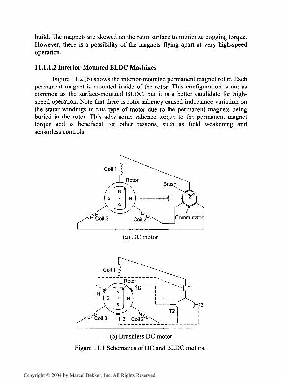
New advancements in fast semiconductor switches and cost-effectiveDSP processors have revolutionized the adjustable speed motor drives. Thesenew opportunities have contributed to novel configurations for electric machinesin which the burden is shifted from complicated structures to software andcontrol algorithms. This in turn has resulted in considerable reduction in cost,while improving the performance of the overall drive system. Brushless DC(BLDC) is one example of this trend. Very compact geometry, high efficiency,and a simple control are among the main incentives for satisfying manyadjustable speed applications with this emerging technology. Figure 11.1 showsthe DC motor and brushless DC motor configurations. The DC motor hasmechanical components, such as commutators and brushes, whereas thebrushless DC motor replaces the mechanical commutators with electronicswitches.
11.1.1 Machine Structure
A BLDC machine can be categorized according to the way the magnetsare mounted on the rotor. The magnets can either be surface mounted or interiormounted.
11.1.1.1 Surface-Mounted BLDC Machines
Figure 11.2 (a) shows the surface mounted permanent magnet rotor. Eachpermanent magnet is mounted on the surface of the rotor. This rotor is simple to
Copyright © 2004 by Marcel Dekker, Inc. All Rights Reserved.
build. The magnets are skewed on the rotor surface to minimize cogging torque.However, there is a possibility of the magnets flying apart at very high-speedoperation.
11.1.1.2 Interior-Mounted BLDC Machines
Figure 11.2 (b) shows the interior-mounted permanent magnet rotor. Eachpermanent magnet is mounted inside of the rotor. This configuration is not ascommon as the surface-mounted BLDC, but it is a better candidate for high-speed operation. Note that there is rotor saliency caused inductance variation onthe stator windings in this type of motor due to the permanent magnets beingburied in the rotor. This adds some salience torque to the permanent magnettorque and is beneficial for other reasons, such as field weakening andsensorless controls.
Coin
(a) DC motor
(b) Brushless DC motor
Figure 11.1 Schematics of DC and BLDC motors.
Copyright © 2004 by Marcel Dekker, Inc. All Rights Reserved.

N
(a) Surface-mounted PM rotor
(b) Interior-mounted PM rotor
Figure 11.2 Cross sectional view of the permanent magnet rotor.
11.1.1.3 Machine Classification
There are two major classes of BLDC motor drives, which can becharacterized by the shapes of their respective back-EMF waveforms:trapezoidal and sinusoidal.
11.1.1.3.1 Trapezoidal Back-EMF
The trapezoidal back-EMF BLDC motor is designed to developtrapezoidal back-EMF waveforms. Ideally, it has the following characteristics:
• Rectangular distribution of magnetic flux in the airgap• Rectangular current waveform• Concentrated stator windings
Copyright © 2004 by Marcel Dekker, Inc. All Rights Reserved.

Excitation of the stator poles is by 120° wide quasi-square currentwaveforms, with a 60° electrical interval of zero current each side, per cycle.The square stator excitation current waveforms, along with the trapezoidal back-EMF, permits important control system simplifications, compared to thesinusoidal back-EMF machines. In particular, the rotor position sensorrequirements are much simpler since only six commutation instants arenecessary per electrical cycle. Figure 11.3 shows the winding configuration ofthe trapezoidal back-EMF BLDC machine.
STATOR
Figure 11.3 Trapezoidal back-EMF BLDC machine winding.
Figure 11.4 (a) shows equivalent circuit and (b) shows trapezoidal back-EMF, stator winding current profiles, and Hall sensor signals of a 3-phaseBLDC motor drive. The voltages seen in this figure (ea, eb, and ec) are the line-to-neutral back-EMF voltages, which are the result of the permanent-magnetflux crossing the airgap in the radial direction and linking the windings of thestator with the rotor speed. The windings of the stator are positioned in thestandard 3-phase full-pitch, concentrated arrangement, and thus the phasetrapezoidal back-EMF waveforms are displaced by 120° electrical degrees. Thestator phase current is on for 120° and off for 60°, resulting in each phasecurrent flowing for 2/3 of the electrical 360° period, 120° positively and 120°negatively. To drive the motor with maximum torque/ampere, it is necessary forthe phase current pulses to be synchronized with the line-neutral back-EMFvoltages of that phase. This is different from the operation of the conventional
Copyright © 2004 by Marcel Dekker, Inc. All Rights Reserved.

synchronous motors in which no rotor position information is required for itsoperation. The BLDC is therefore called a self-synchronous motor.
Hall Sensor A
Hall Sensor B
Hall Sensor C
(a)
K X X X X XI \ 7*/6 y2 n"/6
n/6 it/2 5n/6 it V / / / /
/ / / /
r X X X X XX / X
I l | 1 " 1 1 i iiiiiiiiiT'iTi'ii i";1 u'HTi'n I'lfljiii 1111.,inilil.Iill.Iii ,. iiiiii.ill,,.. ii,i.iii
1
| Phase Current /,, ib.ic / \BackEMF ea, eb, eelF,i| Hall Sensor Signals
Figure 11.4 (a) Three-phase equivalent circuit, (b) back-EMFs, currents, and hallsensor signals.
Copyright © 2004 by Marcel Dekker, Inc. All Rights Reserved.

11.1.1.3.2 Sinusoidal Back-EMF
The sinusoidal back-EMF BLDC motor is designed to develop sinusoidalback-EMF waveforms. It has the following ideal characteristics:
• Sinusoidal distribution of magnetic flux in the airgap• Sinusoidal current waveforms• Sinusoidal distribution of stator conductors
The most fundamental aspect of this motor is that the back-EMF generated ineach phase winding by the rotation of the rotor magnet is a sinusoidal functionof the rotor angle. The stator phase current of a sinusoidal back-EMF BLDCmachine is similar to that of the AC synchronous motor. The rotating statorMMF is similar to that of the synchronous motor and, therefore, can be analyzedwith a phasor diagram. Figure 11.5 shows the winding configuration of thesinusoidal shape back-EMF BLDC machine.
STATOR
Figure 11.5 Sinusoidal back-EMF BLDC machine winding.
11.1.2 Control of the Brushless DC Machine
11.1.2.1 Analysis of BLDC Motor Drive
The analysis of the BLDC drive is based on the following simplifyingassumptions:
• The motor is not saturated.
Copyright © 2004 by Marcel Dekker, Inc. All Rights Reserved.

• Stator resistances of the windings are equal and self- and mutualinductances are constant.
• Power semiconductor devices in the inverter are ideal.• Iron losses are negligible.
Under the above assumptions, a BLDC motor can be represented by
Rs o o0 tfs 0
0 0 R.
Xhic_
+
'L-M 0 0 "
0 £-Af 00 0 L-M_
d•j.dt
ia
hic_
+
ea
6b
ec_
(11.1)
where ea, eb, and ec are back-EMFs and L—M—LS is the stator self-
inductance per phase. The electromagnetic torque is expressed by
T= (11.2)
The interaction of Te with the load torque determines the motor speeddynamics:
(11.3)c#
where 7^ is load torque, 7 is the total rotating inertia, and B is friction. Basedon the equivalent circuit of Figure 11.6, the system equations can be expressed,using the Laplace transform, as
(S) (11.4)
(11.5)
(11.6)
(s) (H.7)
From the above equations, the transfer function of the drive system is
kTOJAS) =
, + sLs ~kE '(11.8)
Copyright © 2004 by Marcel Dekker, Inc. All Rights Reserved.

The physical significance of the electrical and mechanical time constantsin this transfer function is as follows:
• The electrical time constant determines how quickly the armature currentchanges in response to a step change in the terminal voltage, when therotor speed is assumed to be constant.
• The mechanical time constant determines how quickly the speed changesin response to a step change in the motor torque.
Figure 11.6 Simplified equivalent circuit of BLDC motor.
11.1.2.2 Control of BLDC Motor Drive
Figure 11.7 shows the block diagram of the classical position and speedcontrol scheme for a BLDC motor drive. If only speed control is desired, theposition controller and position feedback circuitry may be eliminated. Usually,both position and velocity feedback transducers are required in high-performance position controllers. A position sensor without a velocity sensorwould necessitate differentiating the position signal to obtain the velocity, whichwould tend to amplify noise in an analog system. However, in digital systems,this usually is not a problem. The position sensor, or some other means ofobtaining position information, is required, however, in position and speedcontrol of BLDC motor.
Many high-performance applications include current feedback for torquecontrol. At the minimum, a DC bus current feedback is required to protect thedrive and the machine from over-currents. The controller blocks, "positioncontroller", and "velocity controller" may be any type of classical controllersuch as a proportional-integral (PI) controller or a more advanced controllersuch as an artificial intelligence based controller. The "current controller andcommutation sequencer" provides the properly sequenced gating signals to the3-phase inverter. By comparing the sensed currents with a reference current,current control is achieved by hysteresis control method or some other method.Using position information, the commutation sequencer causes the inverter toelectronically commutate, as in the mechanical commutator in a conventionalDC machine. The commutation angle of each stator winding is selected tomaximize the torque per stator current ampere.
Copyright © 2004 by Marcel Dekker, Inc. All Rights Reserved.

Figure 11.7 Block diagram of a classical speed and position control fora BLDC motor.
The "position sensor" is usually either a 3-element Hall-effect sensor oran optical encoder. The resolver is another option, which allows phase shifting(advancing) of the current pulses with respect to rotor position. Advancing ofthe angle is required due to the electrical time constant of the windings. A givenamount of time is needed for the current to build up. At higher speeds, there isless time available for this current buildup. Furthermore, the growing back-EMF, due to increasing speed, is opposing the rapid rise of the phase current.This is called the field weakening operation of the BLDC. A problem with thistype of operation is that the drive will produce lower torque per ampere, as infield-weakening operations of DC machines.
11.1.3 Sensorless Techniques
Many methods of sensorless operation of BLDC motors have beendescribed in the literature [l]-[47]. The sensorless techniques can be primarilygrouped into the following categories:
• those using measured currents, voltages, fundamental machine equations,and algebraic manipulations
• those using observers• those using back-EMF methods
11.1.3.1 Methods Using Measurables and Math
This consists of two sub-categories: (1) those which calculate the fluxlinkages using measured voltages and currents, and (2) those which utilize amodel's prediction of a measurable voltage or current, compare the model'svalue with the actual measured voltage or current, and calculate the change in
Copyright © 2004 by Marcel Dekker, Inc. All Rights Reserved.

position which is proportional to the difference between the measured and actualvoltage or current. The first sub-category is described in [l]-[8]. Thefundamental idea is to start with the voltage equation of the machine:
V = Ri + — [// (11.9)
where
V is the voltage vector,
I is the current vector,
R is the resistance matrix, and
cp is the flux linkage vector.
This equation is then manipulated to obtain,
(11.10)
With the knowledge of initial position, machine parameters, and the fluxlinkages' relationship to rotor position, the rotor position can be estimated. Bydetermining the rate of change of the flux linkage from the integration results,the speed can also be determined. An advantage of the flux-calculating methodis that line-line voltages may be used in the calculations and, thus, no motorneutral connection is required. This is desirable because the most commonBLDC configuration is the Y-connected stator windings with no neutralconnection.
The second sub-category is described in [9]-[12], This method consists offirst developing an accurate d-q model of the machine. For background in the d-q model of the machine, see the above references. Utilizing the measuredcurrents and their d-q transformation, the output voltages of the model arecompared to the measured and transformed voltages. The difference isproportional to the difference in angular reference between the model'scoordinate system and the actual coordinate system. This is the rotor positionwith reference to the actual coordinate system's reference. Conversely, themeasured voltages are used and the differences in the currents are found. Ineither case, the difference between the measured and the calculated is used asthe multiplier in an update equation for the rotor position.
11.13.2 Methods Using Observers
These methods determine the rotor position and/or speed using observers.The first of these are those utilizing the well-known Kalman filter as a positionestimator [20]-[25]. One of the first to appear in the literature was by M.
Copyright © 2004 by Marcel Dekker, Inc. All Rights Reserved.

Schroedl in 1988. In his many publications, Schroedl utilized various methodsof measuring system voltages and currents, which could produce roughestimates of the angular rotor position. The Kalman filtering added additionalrefinement to the estimates of position and speed. Other observer-based systemsinclude those utilizing non-linear [27]-[29], full-order [2], [30], [31], andsliding-mode observers [1], [10], [32].
Observers are like models of a system, which take as inputs the outputand inputs of the actual system. Typically, the state of the system is produced asthe output. The observer-produced state, or a part of it, can then be fed back intothe system as if it was the actually measured state to be used as in any closed-loop system. The full-order observer is designed using the designer's choice ofeigenvalues. The eigenvalues are usually chosen to be slightly faster (of a largernegative value) than those of the actual system so the state estimation errorapproaches zero as time approaches infinity. If the observer eigenvalues arechosen to be an order of magnitude larger (or more) than the actual system's,then the estimated values will converge to the actual values within a sufficientlyshort time [24].
In [1], [32], and [34], reduced-order observers are utilized to estimate theback-EMF, which is used to derive position and speed. In [29], the rotor positionand speed are directly estimated, as the outputs of a non-linear reduced-orderobserver. Sliding-mode observers, an offspring of the sliding-mode control,utilize a varying switching function in order to confine the state estimation errorto a trajectory which leads toward zero on a phase-plane sliding surface [35]. In[36] and [37], the sliding-mode observers were based on the observation of thed-q transformed stator currents. From the resulting current estimations, the back-EMFs were estimated, producing speed and position estimates.
11.1.3.3 Methods Using Back-EMF Sensing
A) Terminal Voltage Sensing
In normal operation of the BLDC motors, the flat top part of a phaseback-EMF is aligned with the phase current. The switching instants of theconverter can be obtained by knowing the zero-crossings of the back-EMF and aspeed-dependent period of time delay [39]. The method utilizes this concept toestimate commutation instants. The BLDC motor has a rectangular flux densitydistribution in the airgap. For this reason the induced back-EMF in the statorwindings is trapezoidal. By monitoring the phase back-EMF during the silentphase intervals, the zero crossing can be detected. To produce a properswitching pattern for the motor, the terminal voltages are filtered by low passfilters. The low pass filters are used to eliminate higher harmonics in theterminal voltages. Low pass filters can be designed to introduce a near 90-degree phase delay. At the point where a filtered terminal voltage crosses theneutral point voltage, back-EMF of that phase becomes zero and that point
Copyright © 2004 by Marcel Dekker, Inc. All Rights Reserved.

corresponds to the transition at the output of a comparator. Comparator outputscan be decoded to provide the gating signals for the inverter switches.
Since back-EMF is zero at rotor stand-still and proportional to speed afterthat, it is not possible to use the terminal voltage sensing method to obtain aswitching pattern at low speeds. As the speed increases, the average terminalvoltage increases and the frequency of excitation increases. The capacitivereactance in the filters varies with the frequency of excitation, introducing aspeed-dependent delay in switching instants. This speed-dependent reactancedisturbs current alignment with the back-EMF and stator field orientation in theairgap, which causes problems at higher speeds. With this method, a reducedspeed operating range is normally used, typically around 1000-6000 rpm.
In conclusion, the zero-crossing is a good method for steady-stateoperation; however, phase differences in the circuits used due to speedvariations do not allow optimal torque/amp over a wide speed range.
B) Third Harmonic Back-EMF Sensing
Rather than using the fundamental of the phase back-EMF waveform asin the previous technique, the third harmonic of the back-EMF can be used inthe determination of the switching instants in the wye connected 120-degreecurrent conduction operating mode [40]. This method is not as sensitive to phasedelay as the zero voltage crossing method, as the frequency to be filtered is threetimes as high. The reactance of the filter capacitor in this case dominates thephase angle output of the filter.
The terminal voltage equation of the BLDC motor for phase A can beexpressed as
- + ea ( l l . l l )
Back-EMF voltage, ea , is made up of many voltage harmonic components,
ea = E(cos cat + k-, cos 3a>ft + k. cos 5a> J(11.12)
The third harmonic of the terminal voltages is acquired by the summation of theterminal voltages.
v = 3Ek cos 3<cs
= v3(11.13)
The summed terminal voltage contains only the triplens due to the fact that onlyzero sequence current components can flow through the motor neutral. This
Copyright © 2004 by Marcel Dekker, Inc. All Rights Reserved.

voltage is dominated by the third harmonic, which does not require muchfiltering. To obtain switching instants, the filtered voltage signal, which providesthe third harmonic voltage component, is integrated to find the third harmonicflux linkage.
>dt (n.14)
The third harmonic flux linkage lags the third harmonic of the phase back-EMFvoltages by 30 degree. The zero crossings of the third harmonic of the fluxlinkage correspond to the commutation instants of the BLDC motor. The thirdharmonic method provides a wider speed range than the zero-crossing method,does not introduce as much phase delay as the zero-crossing method, andrequires less filtering.
C) Freewheeling Diode Conduction
This method uses indirect sensing of the zero-crossing of the phase back-EMF to obtain the switching instants of the BLDC motor [41]. In the 120 degreeconducting Y-connected BLDC motor, one of the phases is always open-circuited. For a short period after opening the phase, there remains phase currentflowing, via a free-wheeling diode, due to the inductance of the windings. Thisopen phase current becomes zero in the middle of the commutation interval,which corresponds to the point where back-EMF of the open phase crosses zero.The biggest downfall of this method is the requirement of six additional isolatedpower supplies for the comparator circuitry for each free-wheeling diode.
D) Back-EMF Integration
In this method, position information is extracted by integrating the back-EMF of the unexcited phase [42]-[45]. The integration is based on the absolutevalue of the open phase's back-EMF. Integration of the voltage divider scaled-down back-EMF starts when the open phase's back-EMF crosses zero. Athreshold is set to stop the integration which corresponds to a commutationinstant. As the back-EMF is assumed to vary linearly from positive to negative(trapezoidal back-EMF assumed), and this linear slope is assumed speed-insensitive, the threshold voltage is kept constant throughout the speed range. Ifdesired, current advance can be implemented by the change of the threshold.Once the integrated value reaches the threshold voltage, a reset signal is assertedto zero the integrator output.
In conclusion, the integration approach is less sensitive to switchingnoise, and it automatically adjusts to speed changes; but its low speed operationis poor. With this type of sensorless operation scheme, up to 3600 rpm has beenreported [45].
Copyright © 2004 by Marcel Dekker, Inc. All Rights Reserved.

11.1.4 Advantages and Disadvantages of BLDC Motor Drives for VehicularApplications
Advantages of BLDC motors are:
• High efficiency: BLDC motors are the most efficient of all electricmotors. This is due to the use of permanent magnets for the excitation,which consumes no power. The absence of a mechanical commutator andbrushes means low mechanical friction losses and, therefore, higherefficiency.
• Compactness: The recent introduction of high-energy density magnets(rare-earth magnets) has allowed achieving very high flux densities in theBLDC motor. This allows achieving accordingly high torques, which inturn allows making the motor small and light.
• Ease of control: The BLDC motor can be controlled as easily as a DCmotor because the control variables are easily accessible and constantthroughout the operation of the motor.
• Ease of cooling: There is no current circulation in the rotor. Therefore,the rotor of a BLDC motor does not heat up. The only heat production ison the stator, which is easier to cool than the rotor because it is static andon the periphery of the motor.
• Low maintenance, great longevity, and reliability: The absence of brushesand mechanical commutator suppresses the need for associated regularmaintenance and suppresses the risk of failure associated with theseelements. The longevity is therefore only a function of the windinginsulation, bearings, and magnet life-length.
• Low noise emissions: There is no noise associated with the commutationbecause it is electronic and not mechanical. The driving converterswitching frequency is high enough so that the harmonics are not audible.
Disadvantages of BLDC motors are:
• Cost: Rare-earth magnets are much more expensive than other magnetsand result in an increased motor cost.
• Limited constant power range: A large constant power range is crucial toachieving high vehicle efficiencies. The permanent magnet BLDC motoris incapable of achieving a maximum speed greater than twice the basespeed.
• Safety: Large rare-earth permanent magnets are dangerous during theconstruction of the motor because of flying metallic objects attractedtowards them. There is also a danger in case of vehicle wreck if the wheelis spinning freely; the motor is still excited by its magnets and highvoltage is present at the motor terminals that can possibly endanger thepassengers or rescuers.
Copyright © 2004 by Marcel Dekker, Inc. All Rights Reserved.

• Magnet demagnetization: Magnets can be demagnetized by largeopposing magneto motive forces and high temperatures. The criticaldemagnetization force is different for each magnetic material. Great caremust be brought to cooling the motor, especially if it is compactly built.
• High-speed capability: The surface mounted permanent magnet motorscannot reach high speeds because of the limited mechanical strength ofthe assembly between the rotor yoke and the permanent magnets.
• Inverter failures in BLDC motor drives: Because of the permanentmagnets on the rotor, BLDC motors present major risks in case of shortcircuit failures of the inverter. Indeed, the rotating rotor is alwaysenergized and constantly induces an electromotive force in the short-circuited windings. A very large current circulates in those windings andan accordingly large torque tends to block the rotor. The dangers ofblocking one or several wheels of a vehicle are not negligible. If the rearwheels are blocked while the front wheels are spinning, the vehicle willspin uncontrollably. If the front wheels are blocked, the driver has nodirectional control over the vehicle. If only one wheel is blocked, it willinduce a yaw torque that will tend to spin the vehicle, which will bedifficult to control. In addition to the dangers to the vehicle, it should benoted that the large current resulting from an inverter short circuit poses arisk to demagnetize and destroy the permanent magnets.
Open circuit faults in BLDC motor drives are no direct threat to the vehiclestability. The impossibility of controlling a motor due to an open circuit mayhowever pose problems in terms of controlling the vehicle. Because the magnetsare always energized and cannot be controlled, it is difficult to control a BLDCmotor in order to minimize the fault. This is a particularly important issue whenthe BLDC motor is operated in its constant power region. Indeed, in this region,a flux is generated by the stator to oppose the magnet flux and allow the motorto rotate at higher speeds. If the stator flux disappears, the magnet flux willinduce a large electromotive force in the windings, which can be harmful to theelectronics or passengers.
11.2 Switched Reluctance Motor Drives
11.2.1 Basic Operation
The structure of the switched reluctance motor (SRM) is simple, robust,and very reliable in operation. The machine has a salient pole stator withconcentrated excitation windings and a salient pole rotor with no conductors orpermanent magnets. A typical three phase 6/4 switched reluctance motor isshown in Figure 11.8. The motor has six stator poles and four rotor poles. Thecoil is wound around each stator pole and is connected in series with the coil onthe diametrically opposite stator pole to form a phase winding. The reluctance ofthe flux path between the two diametrically opposite stator poles varies as a pair
Copyright © 2004 by Marcel Dekker, Inc. All Rights Reserved.

of the rotor poles rotates into and out of alignment. The inductance of a phasewinding is maximum when the rotor is in aligned position and minimum whenthe rotor is in unaligned position.
Figure 11.8 Cross sectional view of a 6/4 switched reluctance machine.
Figure 11.9 shows a typical change in the stator self-inductance as afunction of the rotor position. The flat portion La of the inductance profile iscaused by a difference in the width between the stator and rotor poles. This flatportion is normally provided to avoid or reduce negative torques duringdemagnetization. Usually, stator poles are made narrow, thus providing morespace for the winding at the same time. A pulse of positive torque is produced ifcurrent flows in a phase winding as inductance of that phase winding isincreasing. A positive voltage is applied to a phase winding in the unalignedrotor position, where the inductance is lowest, and thus, the rate of rise ofcurrent is high. In the region where the rotor poles overlap the excited statorteeth (region of rising inductance), the current level is usually maintainedconstant with the aid of a current chopping regulator. In this region, shear forcesare generated, which tend to align the rotor poles. As the rotor poles approachalignment position, the phase current is commutated. In the aligned position, themagnetic forces will tend to close the air gap by pulling opposite memberstogether. The stator, under such conditions, is subjected to compressive forces
Copyright © 2004 by Marcel Dekker, Inc. All Rights Reserved.

while the rotor is under tension. A negative torque contribution is avoided if thecurrent is reduced to zero before the inductance starts to decrease again.Rotation is maintained by switching on and off the current in the stator phasewinding in synchronism with the rotor position. The ideal inductance profile,ideal phase current, and ideal torque are shown in Figure 11.10.
La
Lu
q2I
93
R R R R
q\ ql q3 q4
Figure 11.9 Ideal inductance profile.
The flux versus current curve is shown in Figure 11.11. The CO, is the
stored field energy, where as G71 is the co-energy.
i
co - energy = m' = \<f>di (11.15)
The torque produced by one phase at any rotor position is given by the equationsbelow.
T = (11.16)
2 dO(11.17)
Copyright © 2004 by Marcel Dekker, Inc. All Rights Reserved.

The positive or negative sign of current does not affect the torque, sincetorque is proportional to the square of current. Torque is totally related to theslop of the inductance. Therefore, phase excited during positive slop givesmotoring mode and phase excited during negative slope gives generating mode.This means that a single machine can be operated as motor as well as generator.
LaIdealInductance
Lu
I deal Current
I deal Torque
Figure 11.10 Ideal current and torque in motoring mode.
flux
current
Figure 11.11 Flux versus current characteristic.
Copyright © 2004 by Marcel Dekker, Inc. All Rights Reserved.

11.2.2 Torque-Speed Characteristics and Control Techniques
The torque-speed curve is shown in Figure 11.12. The torque speed planecan be divided into five regions. Below the base speed, the torque remainsconstant. Base speed (cob) is the lowest speed at which maximum power can beextracted. This region offers the flexibility of current control or hysteresiscontrol to obtain the desired performance from the motor. The controlparameters are Imax, 9on, and 6off. In hysteresis control, we define I,̂ and Imin, orAI. If we decrease the AI, the switching frequency increases. It must be notedthat, at very low speeds (region 1 and 2), motional back-emf is much smallerthan the DC bus voltage and can be neglected. As the speed increases, themotional back-emf is quite considerable (region 3), necessitating theadvancement of the current turn-off angle to obtain a maximum average torque.Hysteresis current control is simple and has variable switching frequency andresidual current ripples as shown in Figure 11.13.
Torque =
speed
Figure 11.12 Torque-speed characteristics of SRM.
When the speed increases further, the motional back-emf exceeds the DCbus voltage and the machine operates in the single pulse mode (region 4). In thismode, the current is limited by the motional back-emf and never reaches therated current. Hence, current control is not possible and the torque is maintainedat the optimal value by controlling the 9on and 00ff angles. Usually, high-speedoperation requires advancement of the turn on angle well before the unalignedposition (Figure 11.14). In this region, torque is inversely proportional to thespeed; therefore, it is called the "constant power region." By further increasingthe speed in the constant power region, the available time for onlinecomputations of the rotor position will be limited. In addition, simultaneousconduction of stator phases in this region will result in an unusual magnetic
Copyright © 2004 by Marcel Dekker, Inc. All Rights Reserved.

distribution in the back iron of the stator with major contribution from mutualfluxes. This mode of operation is called "ultra-high speed" (region 5). It must benoted that this mode of operation will end once continuous conduction in allphases occurs.
• Imax
tain
Figure 11.13 Hysteresis current control of SRM.
-\<k
Figure 11.14 Single pulse operation of SRM.
Copyright © 2004 by Marcel Dekker, Inc. All Rights Reserved.

11.2.3 Power Electronic Driver
The SRM relies upon reluctance torque rather than the more conventionalreactive torque of wound field synchronous, surface magnet PM, and inductionmachines. The SRM is a doubly salient reluctance machine with independentphase windings on the stator. The rotor does not have any winding, and isusually made of steel lamination. The stator and rotor have an unequal numberof poles, with three phase 6/4, four phase 8/6, and three phase 12/8 beingcommon configurations. Due to the absence of rotor windings this motor is verysimple to construct, has low inertia, and allows an extremely high-speedoperation.
The absence of rotor copper loss eliminates the problem, as in aninduction motor, associated with rotor cooling, which has a poor thermal path.SRMs normally are low cost machines for their extremely simple construction.Moreover, due to the unipolar excitation, it is possible to design SRM converterswhich require a minimum of one switch per phase. SRM operation is safe. Thismotor is particularly suitable for hazardous environments. The SRM driveproduces zero or small open circuit voltage and no short circuit current.Furthermore, most SRM converters are immune to shoot through faults, unlikethe inverters of induction and brushless DC motors. A circuit diagram of themost commonly SRM converter, the classical converter, is shown in Figure11.15.
Figure 11.15 Classical SRM converter.
Rapid acceleration and extremely high speed operation in SRM ispossible for its low rotor inertia and simple construction. As was explained,SRM operates in constant torque from zero speed up to the rated speed. Aboverated speed up to a certain speed, the operation is in constant power. The rangeof this constant power operation depends on the motor design and its control.Beyond constant power operation and up to the maximum speed, the motoroperates in the natural mode, where the torque reduces as the square of the
Copyright © 2004 by Marcel Dekker, Inc. All Rights Reserved.

speed. Because of this wide speed range operation, SRM is particularly suitablefor traction applications in propulsion systems.
11.3 References
[I] T. Senjyu and K. Uezato, "Adjustable speed control of brushless DCmotors without position and speed sensors," in Proc. IEEE/IAS Conf. onIndustrial Automation and Control: Emerging Technologies, 1995, pp.160-164.
[2] A. Consoli, S. Musumeci, A. Raciti, and A. Testa, "Sensorless vector andspeed control of brushless motor drives," IEEE Trans, on IndustrialElectronics, vol. 41, pp. 91-96, Feb. 1994.
[3] P. Acarnley, "Sensorless position detection in permanent magnet drives,"IEE Colloquium on Permanent Magnet Machines and Drives, pp. 10/1-10/4, 1993.
[4] T. Liu and C. Cheng, "Adaptive control for a sensorless permanent-magnet synchronous motor drive," IEEE Trans, on Aerospace andElectronic Systems, vol. 30, pp. 900-909, July 1994.
[5] R. Wu and G. R. Slemon, "A permanent magnet motor drive without ashaft sensor," IEEE Trans, on Industry Applications, vol. 27, pp. 1005-1011,Sep./Oct. 1991.
[6] T. Liu and C. Cheng, "Controller design for a sensorless permanentmagnet synchronous drive system," IEE Proc.-B, vol. 140, pp. 369-378,Nov. 1993.
[7] N. Ertugrul, P. P. Acarnley, and C. D. French, "Real-time estimation ofrotor position in PM motors during transient operation," in Proc. IEEFifth European Conf. on Power Electronics and Applications, 1993, pp.311-316.
[8] N. Ertugrul and P. Acarnley, "A new algorithm for sensorless operationof permanent magnet motors," IEEE Trans, on Industry Applications, vol.30, pp. 126-133, Jan./Feb. 1994.
[9] T. Takeshita and N. Matsui, "Sensorless brushless DC motor drive withEMF constant identifier," in Proc. IEEE Conf. on Industrial Electronics,Control, and Instrumentation, vol. 1, 1994, pp. 14-19.
[10] N. Matsui and M. Shigyo, "Brushless DC motor control without positionand speed sensors," IEEE Trans, on Industry Applications, vol. 28, pp.120-127, Jan./Feb. 1992.
[II] N. Matsui, "Sensorless operation of brushless DC motor drives," in Proc.IEEE Conf. on Industrial Electronics, Control, and Instrumentation, vol.2, Nov. 1993, pp. 739-744.
[12] N. Matsui, "Sensorless PM brushless DC motor drives," IEEE Trans, onIndustrial Electronics, vol. 43, pp. 300-308, April 1996.
[13] M. A. Hoque and M. A. Rahman, "Speed and position sensorlesspermanent magnet synchronous motor drives," in Proc. 1994 Canadian
Copyright © 2004 by Marcel Dekker, Inc. All Rights Reserved.

Conf. on Electrical and Computer Engineering, vol. 2, Sep. 1994, pp.689-692.
[14] H. Watanabe, H. Katsushima, and T. Fujii, "An improved measuringsystem of rotor position angles of the sensorless direct drive servomotor,"in Proc. IEEE 1991 Conf. on Industrial Electronics, Control, andInstrumentation, 1991, pp. 165-170.
[15] J. S. Kim and S. K. Sul, "New approach for the low speed operation ofthe PMSM drives without rotational position sensors," IEEE Trans, onPower Electronics, vol. 11, pp. 512-519, 1996.
[16] A. H. Wijenayake, J. M. Bailey, and M. Naidu, "A DSP-based positionsensor elimination method with on-line parameter identification schemefor permanent magnet synchronous motor drives," IEEE Conf. Record ofthe 13th Annual IAS Meeting, vol. 1, 1995, pp. 207-215.
[17] H. Watanabe, S. Miyazaki, and T. Fujii, "Improved variable speedsensorless servo system by disturbance observer," 16th Annual Conf. ofIEEE Industrial Electronics Society, vol. 1, pp. 40-45, 1990.
[18] J. Oyama, T. Abe, T. Higuchi, E. Yamada, and K. Shibahara, "Sensor-less control of a half-wave rectified brushless synchronous motor," Conf.Record of the 1995 IEEE Industry Applications Conf., vol. 1, pp. 69-74,1995.
[19] J. S. Kim and S. K. Sul, "New approach for high performance PMSMdrives without rotational position sensors," IEEE Conf. Proc. 1995,Applied Power Electronics Conf. and Exposition, vol. 1, pp. 381-386,1995.
[20] M. Schrodl, "Digital implementation of a sensorless control algorithm forpermanent magnet synchronous motors," Proc. Int'l. Conf. "SM 100",ETH Zurich (Switzerland), pp. 430-435, 1991.
[21] M. Schrodl, "Operation of the permanent magnet synchronous machinewithout a mechanical sensor," IEE Proc. Int'l. Conf. on Powerelectronics and Variable Speed Drives, pp. 51-56, July 1990.
[22] M. Schrodl, "Sensorless control of permanent magnet synchronousmotors," Electric Machines and Power Systems, vol. 22, pp. 173-185,1994.
[23] B. J. Brunsbach, G. Henneberger, and T. Klepsch, "Position controlledpermanent magnet excited synchronous motor without mechanicalsensors," IEE Conf. on Power Electronics and Applications, vol. 6, pp.38-43, 1993
[24] R. Dhaouadi, N. Mohan, and L. Norum, "Design and implementation ofan extended Kalman filter for the state estimation of a permanent magnetsynchronous motor," IEEE Trans, on Power Electronics, vol. 6, pp. 491-497, July 1991.
[25] A. Bado, S. Bolognani, and M. Zigliotto, "Effective estimation of speedand rotor position of a PM synchronous motor drive by a Kalman filtering
Copyright © 2004 by Marcel Dekker, Inc. All Rights Reserved.

technique," PESC'92 Record, 23rd Annual IEEE Power ElectronicsSpecialist Conf., vol. 2, pp. 951-957, 1992.
[26] M. S. Santini, A. R. Stubberud, and G. H. Hosteller, Digital ControlSystem Design, New York: Saunders College Publishing, 1994.
[27] K. R. Shouse and D. G. Taylor, "Sensorless velocity control ofpermanent-magnet synchronous motors," Proc. of the 33rd Conf. onDecision and Control, pp. 1844-1849, Dec. 1994.
[28] J. Hu, D. M. Dawson, and K. Anderson, "Position control of a brushlessDC motor without velocity measurements," IEE Proc. on ElectronicPower Applications, vol. 142, pp. 113-119, March 1995.
[29] J. Solsona, M. I. Valla, and C. Muravchik, "A nonlinear reduced orderobserver for permanent magnet synchronous motors," IEEE Trans, onIndustrial Electronics, vol. 43, pp. 38-43, Aug. 1996.
[30] R. B. Sepe and J. H. Lang, "Real-time observer-based (adaptive) controlof a permanent-magnet synchronous motor without mechanical sensors,"IEEE Trans, on Industry Applications, vol. 28, pp. 1345-1352, Nov./Dec.1992.
[31] L. Sicot, S. Siala, K. Debusschere, and C. Bergmann, "Brushless DCmotor control without mechanical sensors," IEEE Power ElectronicsSpecialist Conf., pp. 375-381, 1996.
[32] T. Senjyu, M. Tomita, S. Doki, and S. Okuma, "Sensorless vector controlof brushless DC motors using disturbance observer," PESC'95 Record,26lh Annual IEEE Power Electronics Specialists Conf., vol. 2, pp. 772-777, 1995.
[33] R. Bronson, Matrix Methods - An Introduction, New York: AcademicPress, Inc., 1991.
[34] J. Kim and S. Sul, "High performance PMSM drives without rotationalposition sensors using reduced order observer," Record of the 1995 IEEEIndustry Applications Conf., vol. 1, pp. 75-82, 1995.
[35] Y. Kim, J. Ahn, W. You, and K. Cho, "A speed Sensorless vector controlfor brushless DC motor using binary observer," Proc. of the 1996 IEEEIECON 22nd Int'l. Conf. on Industrial Electronics, Control, andInstrumentation, vol. 3, pp. 1746-1751, 1996.
[36] T. Furuhashi, S. Sangwongwanich, and S. Okuma, "A position-and-velocity Sensorless control for brushless DC motors using an adaptivesliding mode observer," IEEE Trans, on Industrial Electronics, vol. 39,pp. 89-95, April 1992.
[37] Z. Peixoto and P. Seixas, "Application of sliding mode observer forinduced e.m.f, position and speed estimation of permanent magnetmotors," IEEE Conf. Proc. of IECON, pp. 599-604, 1995.
[38] J. Hu, D. Zhu, Y. Li, and J. Gao, "Application of sliding observer tosensorless permanent magnet synchronous motor drive system," IEEEPower Electronics Specialist Conf., vol. 1, pp. 532-536, 1994.
Copyright © 2004 by Marcel Dekker, Inc. All Rights Reserved.

[39] K. lizuka, H. U/uhashi, and M. Kano, "Microcomputer control forsensorless brushless motor," IEEE Trans, on Industry Applications, vol.IA-27, pp. 595-601, May/June 1985.
[40] J. Moreira, "Indirect sensing for rotor flux position of permanent magnetAC motors operating in a wide speed range," IEEE Trans, on IndustryApplications Society, vol. 32, pp. 401-407, Nov./Dec. 1996.
[41] S. Ogasawara and H. Akagi, "An approach to position sensorless drivefor brushless DC motors," IEEE Trans, on Industry Applications, vol. 27,pp. 928-933, Sep./Oct. 1991.
[42] T. M. Jahns, R. C. Becerra, and M. Ehsani, "Integrated current regulationfor a brushless ECM drive," IEEE Trans, on Power Electronics, vol. 6,pp. 118-126, Jan. 1991.
[43] R. C. Becerra, T. M. Jahns, and M. Ehsani, "Four-quadrant sensorlessbrushless ECM drive," IEEE Applied Power Electronics Conf. andExposition, pp. 202-209, March 1991.
[44] D. Regnier, C. Oudet, and D. Prudham, "Starting brushless DC motorsutilizing velocity sensors," Proc. of the 14th Annual Symposium onIncremental Motion Control Systems and Devices, Champaign, Illinois:Incremental Motion Control Systems Society, pp. 99-107, June 1985.
[45] D. Peters and J. Harth, "I.C.s provide control for sensorless DC motors,"EDN, pp. 85-94, April 1993.
[46] J. P. Johnson, "Synchronous-misalignment detection/correction techniqueof sensorless BLDC control," Ph.D. Dissertation, Texas A&M University,1998.
[47] J. R. Hendershot and T. J. E. Miller, Design of Brushless Permanent-Magnet Motors, Oxford, 1994.
[48] T. J. E. Miller and J. R. Hendershot, Switched Reluctance Motors & TheirControls, Magna Physics Publishing, Madison, WI, 1993.
[49] R. Krishnan, Switched Reluctance Motor Drives: Modeling, Simulation,Analysis, Design, and Applications, CRC Press, 2001.
[50] M. Barnes and C. Pollock, "Power electronic converters for switchedreluctance drives," IEEE Transactions on Power Electronics, vol. 13, pp.1100-1 111, Nov. 1998.
[51] V. R. Stefanovic and S. Vukosavic, "SRM inverter topologies: acomparative evaluation," IEEE Transactions on Industry Applications,vol. 27, pp. 1034-1047, Nov./Dec. 1991.
[52] K. W. E. Cheng, D. Sutanto, C. Y. Tang, X. D. Xue, and Y. P. B. Yeung,"Topology analysis of switched reluctance drives for electric vehicle," inProc. 81 International Power Electronics and Variable Speed DrivesConf., 2000, pp. 512-517.
[53] B. Fahimi, G. Suresh, J. Mahdavi, and M. Ehsani, "A new approach tomodel switched reluctance motor drive: application to analysis, designand control," in Proc. IEEE Power Electronics Specialists Conference,Fukuoka, 1998.
Copyright © 2004 by Marcel Dekker, Inc. All Rights Reserved.

[54] J. Mahdavi, G. Suresh, B. Fahimi, and M. Ehsani, "Dynamic modeling ofnon-linear SRM using Pspice," in Proc. IEEE Industry ApplicationsSociety Annual Meeting, New Orleans, 1997.
[55] S. Filizadeh, L. S. Safavian, and A. Emadi, "Control of variablereluctance motors: A comparison between classical and Lyapunov-basedfuzzy schemes," Journal of Power Electronics, pp. 305-311, Oct. 2002.
Copyright © 2004 by Marcel Dekker, Inc. All Rights Reserved.