dl.booktolearn.comdl.booktolearn.com/ebooks2/engineering/... · 2019-06-24 · contents preface ix...
TRANSCRIPT

VOICE OVER LTE

VOICE OVER LTEVoLTE
Miikka Poikselka, Harri Holma, Jukka Hongisto,Juha Kallio and Antti ToskalaNokia Siemens Networks, Finland
A John Wiley & Sons, Ltd., Publication

This edition first published 2012© 2012 John Wiley & Sons Ltd
Registered officeJohn Wiley & Sons Ltd, The Atrium, Southern Gate, Chichester, West Sussex, PO19 8SQ, United Kingdom
For details of our global editorial offices, for customer services and for information about how to apply for permission toreuse the copyright material in this book please see our website at www.wiley.com.
The right of the author to be identified as the author of this work has been asserted in accordance with the Copyright,Designs and Patents Act 1988.
All rights reserved. No part of this publication may be reproduced, stored in a retrieval system, or transmitted, in anyform or by any means, electronic, mechanical, photocopying, recording or otherwise, except as permitted by the UKCopyright, Designs and Patents Act 1988, without the prior permission of the publisher.
Wiley also publishes its books in a variety of electronic formats. Some content that appears in print may not be availablein electronic books.
Designations used by companies to distinguish their products are often claimed as trademarks. All brand names andproduct names used in this book are trade names, service marks, trademarks or registered trademarks of their respectiveowners. The publisher is not associated with any product or vendor mentioned in this book. This publication is designedto provide accurate and authoritative information in regard to the subject matter covered. It is sold on the understandingthat the publisher is not engaged in rendering professional services. If professional advice or other expert assistance isrequired, the services of a competent professional should be sought.
Library of Congress Cataloging-in-Publication Data
Poikselka, Miikka.Voice over LTE (VoLTE) / Miikka Poikselka, Harri Holma, Jukka Hongisto, Juha Kallio and Antti Toskala.
pages cmIncludes bibliographical references and index.
ISBN 978-1-119-95168-11. Long-Term Evolution (Telecommunications) 2. Internet telephony. I. Holma, Harri, 1970- II. Hongisto, Jukka. III.Kallio, Juha. IV. Toskala, Antti. V. Title.
TK5103.48325.P65 2012621.3845′6–dc23
2011047199
A catalogue record for this book is available from the British Library.
Print ISBN: 9781119951681
Set in 10/12 Times by Laserwords Private Limited, Chennai, India

Contents
Preface ix
Acknowledgements xi
List of Abbreviations xiii
1 Background 1
2 VoLTE Deployment Strategies 52.1 Common Networks Everywhere 52.2 GSM/WCDMA View 62.3 CDMA View 6
3 VoLTE System Architecture 93.1 Overview 93.2 LTE Radio 10
3.2.1 LTE Radio Background 103.2.2 LTE Radio Architecture 11
3.3 Evolved Packet Core 143.3.1 What is the Evolved Packet Core? 143.3.2 EPC Entities and Functionalities 143.3.3 EPS Mobility Management 173.3.4 EPS Session Management and QoS 20
3.4 Control 223.4.1 What is an IP Multimedia Subsystem? 223.4.2 IMS Development History 233.4.3 IMS Fundamentals 263.4.4 IMS Entities 323.4.5 Home Subscriber Server 423.4.6 Policy and Charging Rule Function 43
3.5 Summary 44

vi Contents
4 VoLTE Functionality 474.1 Overview 474.2 Radio Functionalities 47
4.2.1 Bearers and Scheduling 474.2.2 Mobility 494.2.3 Circuit Switched Fallback Handover 514.2.4 Mobility from 2G/3G Back to LTE 544.2.5 Power Saving Features 554.2.6 Positioning Solutions 564.2.7 UE Radio Access Capabilities for VoLTE 57
4.3 EPC Functionalities 584.3.1 LTE subscriber identification 594.3.2 PDN Connectivity Establishment for the VoLTE User 604.3.3 EPS Dedicated Bearer Setup 65
4.4 IMS Identification 654.4.1 IP Multimedia Services Identity Module 664.4.2 Public User Identity 674.4.3 Private User Identity 674.4.4 Relationship between Private and Public User Identities 674.4.5 Identification of User’s Device 684.4.6 Identification of Network Entities 704.4.7 Identification of Services (Public Service Identities) 704.4.8 Identification Without ISIM 70
4.5 IMS Service Provisioning 714.5.1 Enforcement of Allowed Services 724.5.2 Service-Triggering Information 734.5.3 Selection of AS 754.5.4 AS Behaviour 754.5.5 Service Provisioning in Action 76
4.6 IMS Multimedia Telephony 794.6.1 Introduction 794.6.2 Multimedia Communication 804.6.3 Supplementary Services 81
5 VoLTE End to End and Signalling 995.1 Overview 995.2 VoLTE Subscription and Device Configuration 1005.3 EPS Attach for CSFB/IMS VoIP and Default Bearer Activation 1025.4 IMS Registration 107
5.4.1 Constructing the REGISTER Request 1095.4.2 From the UE to the P-CSCF 1105.4.3 From the P-CSCF to the I-CSCF 1105.4.4 From the I-CSCF to the S-CSCF 1115.4.5 S-CSCF Challenges the UE 111

Contents vii
5.4.6 UE’s Response to the Challenge 1125.4.7 Registration at the S-CSCF 1135.4.8 The 200 (OK) Response 1135.4.9 Third-Party Registration to Application Servers 1145.4.10 Subscription to Registration Event Package 1155.4.11 Re-Registration and Re-Authentication 1155.4.12 De-Registration 1165.4.13 Related Standards 117
5.5 IMS VoIP Session 1185.5.1 Constructing the INVITE Request 1205.5.2 Routing 1225.5.3 Media Negotiation 1275.5.4 Media Resource Reservation and Policy Control 1295.5.5 Charging 1355.5.6 Session Release 1415.5.7 Related Standards 143
5.6 Voice Continuity 1445.6.1 PS-PS Intersystem Handover 1445.6.2 Single Radio Voice Call Continuity 1455.6.3 Summary 157
5.7 IMS Emergency Session 1605.7.1 PDN Connection Setup for Emergency Session 1605.7.2 Emergency Registration 1615.7.3 Emergency Session 163
5.8 CS Fallback for Evolved Packet System Call Case(s) 1645.8.1 Architecture of CS Fallback for EPS 1665.8.2 Description of SGs Interface 1685.8.3 Idle Mode Signalling Reduction and Use of CS
Fallback for EPS 1695.8.4 Idle Mode versus Active Mode UE with CS
Fallback for EPS 1725.8.5 CS Fallback Attachment 1735.8.6 Mobile Originating Call Using CSFB 1745.8.7 Mobile Terminating Call Using CSFB 1805.8.8 Call Unrelated CSFB Procedures 1875.8.9 Mobile Terminating Roaming Retry and Forwarding 1895.8.10 Summary 193
5.9 VoLTE Messaging 1945.9.1 Native IMS Messaging 1945.9.2 SMS Interworking 1965.9.3 Multimedia Messaging Service 2145.9.4 Unstructured Supplementary Services Data Simulation in IMS 2145.9.5 Summary 215

viii Contents
6 IMS Centralized Services 217
7 VoLTE Radio Performance 2237.1 Coverage 2237.2 Capacity 2247.3 Latency 2267.4 Summary 228
8 HSPA Voice over IP 229
References 233
Index 237

Preface
Voice communication has become mobile in a massive way and the mobile is the preferredway for voice communication for more than six billion subscribers. The introduction ofhigh speed packet access (HSPA) also allows a large set of data services from smartphones,tablets and laptops to go mobile. The data volumes in mobile networks greatly exceedthe voice volumes – from the traffic point of view, networks have already turned fromvoice dominated to data dominated. The next generation mobile radio system, called longterm evolution (LTE), started commercially in 2009 and is designed to boost further thedata rates and capacities. LTE radio is primarily optimised for high capacity data but canalso support voice efficiently. During 2012, smartphones with the capability to provide avoice service using the LTE network are becoming available. This book describes how thevoice service is supported with LTE capable terminals. The voice support in LTE is not astrivial as in second generation (2G) GSM and third generation (3G) WCDMA solutionswhere circuit switched (CS) voice was used, since LTE is designed only for packetswitched (PS) connections. The voice service in LTE uses the voice over Internet protocol(VoIP) – called VoLTE (voice over LTE) – together with the IP multimedia system (IMS).There are also alternative solutions for supporting voice in the initial phase where thevoice service runs on legacy 2G/3G networks while only data is carried on LTE. Thevoice solutions, architectures and required functionalities are described in this book.
The book is structured as follows. Chapter 1 gives the background and Chapter 2describes the operator VoLTE deployment strategies. The system architecture is presentedin Chapter 3 and VoLTE functionalities in Chapter 4. End to end signalling is illustratedin Chapter 5 and IMS centralized services in Chapter 6. The VoLTE radio performanceis presented in Chapter 7 and the VoIP over HSPA networks in Chapter 8.
LTE will access a very large global market – not only GSM/WCDMA operators, butalso CDMA and WiMAX operators and potentially also fixed network service providers.The large potential market can attract a large number of companies to the market placepushing the economics of scale, which enables wide scale LTE adoption with lower cost.The voice solution is a key part of the system design – every single LTE capable smart-phone needs to have a good quality voice solution. This book is particularly designed forchip set and mobile vendors, network vendors, network operators, technology managersand regulators who would like to get a deeper understanding of voice over LTE.

Acknowledgements
We would like to thank the following colleagues for their valuable comments: JariValimaki, Peter Leis, Curt Wong and Martin Ottl.
The authors appreciate the fast and smooth editing process provided by John Wiley &Sons Ltd and especially Susan Barclay, Sandra Grayson, Sarah Tilley, Sophia Travis andMark Hammond.
We are grateful to our families for their patience during the late night and weekendediting sessions.
The authors welcome any comments and suggestions for improvements or changesthat could be used to improve future editions of this book. The feedback is welcomedto the authors’ email addresses - [email protected], [email protected],[email protected], [email protected] and [email protected].

List of Abbreviations
1×RTT Single carrier radio transmission technology3GPP Third generation partnership project3GPP2 Third generation partnership project 2AAA Authentication, authorization and accountingAAL ATM adaptation layerAAR AA requestACA Accounting answerACK AcknowledgementACR Accounting requestAGCF Access gateway control functionA-GNSS Assisted global navigation satellite systemAGW Access gatewayAKA Authentication and key agreementALG Application level gatewayAMR Adaptive multi-rateAMR-WB Adaptive multi-rate widebandAOC Advice of chargeAP Authentication proxyAPN Access point nameAPN-AMBR Access point name–aggregate maximum bit rateARP Allocation and retention priorityAS Application serverASA Abort session answerASR Abort session requestATCF Access transfer control functionATGW Access transfer gatewayATM Asynchronous transfer modeAUC Authentication centreAUID Application usage identificationAUTN Authentication token

xiv List of Abbreviations
AVC Advanced video codingAVP Attribute value pair; audio visual profileAVPF Audio visual profile with feedbackB2BUA Back to back user agentBGCF Breakout gateway control functionBICC Bearer independent call controlBS Billing systemBSC Base station controllerBSS Base station systemBTS Base transceiver stationCAT Customized alerting toneCB Communication barringCCBS Completion of communications to busy subscriberCCF Charging collection functionCCNR Completion of communications on no replyCD Communication deflectionCDF Charging data functionCDMA Code division multiple accessCDR Charging data recordCLI Calling line identificationCN Core networkCSFB Circuit switched fallbackDCH Dedicated traffic channelPCH Paging channelCFB Communication forwarding busyCFNL Communication forwarding on not logged inCFNR Communication forwarding no replyCFNRc Communication diversion on mobile subscriber not
reachableCFU Communication forwarding unconditionalCGF Charging gateway functionCGI Cell global identificationCK Ciphering keyCLIP Calling line identification presentationC-MSISDN Correlation mobile subscriber international ISDN
numberCONF Conference callingCPC Continuous packet connectivityCPE Customer premise equipmentCRS Customized ringing signalCS Circuit switchedCSCF Call session control functionCSFB Circuit switched fallbackCSMO Circuit switched mobile originatingCTF Charging trigger function
List of Abbreviations xv
CUG Closed user groupCW Communication waitingDCH Dedicated channelDFCA Dynamic frequency and channel allocationDL DownlinkDNS Domain name systemDOCSIS Data over cable service interface specificationDPCCH Dedicated physical control channelDPDCH Dedicated physical data channelDRB Data radio bearerDRX Discontinuous receptionDTAP Direct transfer application partDTM Dual transfer modeDTMF Dual-tone Multi-frequencyDTX Discontinuous transmissionEATF Emergency access transfer functionECF Event charging functionECM Evolved packet system connection managementE-CSCF Emergency CSCFECT Explicit communication transferE-DCH Enhanced dedicated channelEDGE Enhanced data rates for global evolutionEFR Enhanced full rateeHRPD Evolved high rate packet dataEMM Evolved packet system mobility managementeMSS Enhanced mobile switching centre servereNB Evolved nodeBeNodeB Evolved nodeBEPC Evolved packet coreePDG Evolved packet data gatewayEPS Evolved packet systemE-SMLC Evolved serving mobile location centreE-STN-SR Emergency session transfer number for SRVCCETSI European Telecommunications Standards InstituteE-UTRAN Evolved universal mobile telecommunications
system terrestrial radio access networkEV-DO Evolution data onlyFA Flexible alertingFGI Feature group indicatorFoR Follow on requestFTP File transfer protocolGAA Generic authentication architectureGBR Guaranteed bit rateGERAN Global system for mobile communications/EDGE
radio access network

xvi List of Abbreviations
GGSN Gateway general packet radio servicesupport node
GMLC Gateway mobile location centreGPRS General packet radio serviceGPS Global positioning systemGRUU Globally routable user agent URIGSM Global system for mobile communicationsGSMA GSM associationGTP GPRS tunnelling protocolGTP-C GPRS tunnelling protocol control planeGTP-U GPRS tunnelling protocol user planeGWF Gateway functionHARQ Hybrid automatic repeat requestHLR Home location registerHOLD Communication holdHPLMN Home public land mobile networkHRPD High rate packet dataHSDPA High speed downlink packet accessHS-DSCH High speed downlink shared channelHSGW HRPD serving gatewayHSPA High speed packet accessHSS Home subscriber serverHSUPA High speed uplink packet accessHTTP Hyper text transfer protocolIAM Initial address messageIBCF Interconnection border control functionICID Internet protocol multimedia subsystem charging
identifierICS Internet protocol multimedia subsystem centralised
servicesI-CSCF Interrogating CSCFICSI Internet protocol multimedia subsystem
communication service identificationIETF Internet engineering task forceiFC Initial filter criteriaIK Integrity keyIM Instant messagingIMEI International mobile equipment identityIMPI IMS private user identityIMPU Internet protocol multimedia subsystem public user
identityIMS Internet protocol multimedia subsystemIMSI International mobile subscriber identifierIMS-MGW IMS media gatewayIM-SSF Internet protocol multimedia service switching
function

List of Abbreviations xvii
IMTC International multimedia teleconferencingconsortium
IOI Inter-operator identifierIP Internet protocolIP-CAN IP connectivity access networkIP-PBX IP private branch exchangeIPsec Internet protocol securityIP-SM-GW IP short message gatewayIPv4 Internet protocol version 4IPv6 Internet protocol version 6ISC IMS service controlISDN Integrated services digital networkISIM IP multimedia services identity moduleISR Idle mode signaling reductionISUP ISDN user partLAI Location area identityLCS Location control servicesLIA Location info answerLIR Location info requestLRF Location retrieval functionLTE Long term evolutionMAA Multimedia–multimedia answerMAC Medium access controlMaM Mid-call assisted mobile switching centre serverMAP Mobile application partMAR Multimedia authorisation requestMBR Maximum bit rateMCC Mobile country codeMCID Malicious communication identificationME Mobile equipmentMGCF Media gateway control functionMGW Media gateway functionMIME Multipurpose Internet mail extensionMI-USSD Mobile initiated unstructured supplementary
service dataMME Mobility management entityMMS Multimedia messaging serviceMMTel Multimedia telephony communication serviceMNC Mobile network codeMO-LR Mobile originating location requestMRB Media resource brokerMRFC Multimedia resource function controllerMRFP Media resource function processorMSC Mobile switching centreMSIN Mobile subscriber identification numberMSISDN Mobile subscriber ISDN

xviii List of Abbreviations
MSRN Mobile station roaming numberMSRP Message session relay protocolMSS MSC serverMT-LR Mobile terminating location requestMTP Message transfer partMTRF Mobile terminating roaming forwardingMTRR Mobile terminating roaming retryMTU Maximum transmission unitMWI Message waiting indicationNACC Network assisted cell changeNAI Network access identifierNAS Network access stratumNAT Network address translatorNB NarrowbandNDS Network domain securityNGMN Next generation mobile networks allianceNGN Next generation networkNI-USSD Network initiated unstructured supplementary
service dataNW NetworkOCS Online charging systemOFDMA Orthogonal frequency division multiple accessOIP Originating identification presentationOIR Originating identification restrictionOMA Open mobile allianceOSA Open service architectureOTDOA Observed time difference of arrivalPCC Policy and charging controlPCEF Policy enforcement functionPCRF Policy and charging rules functionP-CSCF Proxy-CSCFPDCCH Physical downlink control channelPDCP Packet data convergence protocolPDN Packet data networkPDP Packet data protocolPDSCH Physical downlink shared channelP-GW PDN gatewayPHY Physical layerPLMN Public land mobile networkPNM Personal network managementPoC Push to talk over cellularPOTS Plain old telephone servicePRACK Provisional response acknowledgementPRN Provide roaming numberPS Packet switched; presence serverPS HO Packet switched handover

List of Abbreviations xix
PSAP Public safety answering pointPSTN Public switched telephone networkQCI QoS class identifierQoS Quality of serviceRAA Re-authorisation requestRAB Radio access bearerRAN Radio access networkRAND Random challengeRAR Re-authorisation requestRAT Radio access technologyRCS Rich communication suiteRDF Routing determination functionRES ResponseRF Radio frequencyRFC Requests for commentsRLC Radio link controlRNC Radio network controllerRoHC Robust header compressionRR Receiver reportsRRC Radio resource controlRSH Resume call handlingRSRP Reference symbol received powerRSRQ Reference signal received qualityRTCP Real-time transport protocol control protocolRTP Real-time transport protocolRTP/AVP RTP audio and video profileS1AP S1 application protocolSA Security associationSAA Server assignment answerSAE System architecture evolutionSAI Service area identifierSAR Server assignment requestSCC AS Service centralisation and continuity application
serverSCCP Signalling connection control partSC-FDMA Single carrier FDMAS-CSCF Serving CSCFSCTP Stream control transmission protocolSDP Session description protocolSEG Security gatewaySGsAP SGs application partSGSN Serving GPRS support nodeS-GW Serving gatewaySIB System information blockSIM Subscriber identity moduleSIP Session initiation protocol

xx List of Abbreviations
SLF Subscription locator functionSM Short messageSMS Short message serviceSMSC Short message service centreSPR Subscription profile repositorySPS Semi persistent schedulingSPT Service point triggerSQN Sequence numberSR-VCC Single radio voice call continuitySRVCC Single radio voice call continuitySUPL Secure user plane locationSV-DO Simultaneous voice and data onlySV-LTE Simultaneous voice and LTETA Tracking areaTAI Tracking area identityTAS Telephony application serverTCP Transmission control protocolTFT Traffic flow templateTHIG Topology hiding inter-network gatewayTIP Terminating identification presentationTIR Terminating identification restrictionTISPAN Telecommunications and Internet converged
services and protocols for advanced networkingTLS Transport layer security protocolTLV Tag length valueTMR Transport medium requirementTMSI Temporary mobile subscriber identityTrGW Transition gatewayTTI Transmission time intervalUA User agentUDP User datagram protocolUE User equipmentUE-AMBR UE aggregate maximum bit rateUICC Universal integrated circuit cardUL UplinkUM Unacknowldeged modeUMTS Universal mobile telecommunications systemURA UTRAN registration areaURI Uniform resource identifierURL Universal resource locatorUSI User service informationUSIM Universal subscriber identity moduleUSSD Unstructured supplementary service dataUSSI Unstructured supplementary services data
simulation in IMSUTDOA Uplink time difference of arrival

List of Abbreviations xxi
UTRAN UMTS terrestrial radio access networkVLR Visitor location registerVMSC Visited MSCVoIP Voice over IPVoLGA Voice over LTE via generic accessVoLTE Voice over LTEVPLMN Visited PLMNWCDMA Wideband code division multiple accessWLAN Wireless local area networkXCAP XML configuration access protocolXDM XML document managementXDMS XML document management serverxDSL Digital subscriber lineXML Extensible markup languageXRES Expected response

1Background
At the end of 2004 the third generation partnership project (3GPP) Standardisation Forumstarted to evaluate a new radio technology as a successor for wideband code division mul-tiple access (WCDMA). This work was called long term evolution (LTE) and is nowadaysthe radio interface name used in most official publications. Inside 3GPP the newly devel-oped radio access network is called the evolved UMTS terrestrial radio access network(E-UTRAN) to indicate the path from the global system for mobile communications(GSM)/Enhanced data rates for global evolution (EDGE) radio access network (GERAN)via the GSM/general packet radio service (GPRS)/EDGE to UTRAN [WCDMA/high-speed packet access (HSPA)] and finally to E-UTRAN (LTE). In parallel to the work ona new radio interface 3GPP initiated a study to evolve the 2G/3G packet core network(known as the GPRS core) in order to cope with the new demands of LTE. This corenetwork study was called system architecture evolution (SAE) and it was documentedin the 3GPP technical report (3GPP TR 23.882). The final outcome of this work was anew packet core design in Release 8 documented in (3GPP TS 23.401) and (3GPP TS23.402), called the evolved packet core (EPC). 3GPP Release 8 was officially completedin March 2009 and the world’s first commercial LTE network was opened in December2009 by TeliaSonera.
3GPP Release 8 introduces major advances in mobile networks. For the subscriber,it means higher access rates and lower latency on the connection, while for the mobilecommunication service provider, LTE radio technology provides lower cost per transmittedbit thanks to more efficient use of radio network resources and delivers excellent voicespectral efficiency, as described in Chapter 7. The technology also offers more flexibilityin frequency allocation, thanks to the ability to operate LTE networks across a very widespectrum of frequencies. LTE also minimises the power consumption of terminals that areused ‘always on’. 3GPP Release 8 also introduces major advances in the core network thatimprove service quality and networking efficiency, leading to a better end user experience.GPRS technology has already introduced the always on concept for subscriber connectivityand 3GPP Release 8 mandates this ability, with at least one default bearer being alwaysavailable for all subscribers. This allows fast access to services as well as network initiatedservices such as terminating voice calls and push e-mail. The connection setup time forperson to person communication is also minimised with always on bearers.
Voice over LTE: VoLTE, First Edition. Miikka Poikselka, Harri Holma, Jukka Hongisto, Juha Kallio and Antti Toskala.© 2012 John Wiley & Sons, Ltd. Published 2012 by John Wiley & Sons, Ltd.

2 Voice over LTE
But considering the fact that LTE is an all-internet protocol (IP) technology we can get tothe conclusion that the voice service will have to be delivered in a different way as circuitswitched voice will not be possible. So there is a need for a voice solution on top of LTE.Voice in this IP world, would be implemented as voice over Internet protocol (VoIP). The3GPP-specified way to support VoIP is the IP multimedia subsystem (IMS). It is an access-independent and standard-based IP connectivity and service control architecture thatenables various types of multimedia services to end users using common Internet-basedprotocols. 3GPP has worked with the IMS since 2000 and there exist thousands of pages, indifferent specifications, that cover IMS related functionalities. In the meantime, a sophis-ticated architecture and feature set has been developed. Moreover, 3GPP has specifiedmultiple, different ways to complete single functions (e.g. authentication, session setup,supplementary service execution, bearer setup) which increases complexity of the IMS.
While 3GPP has specified all of the ‘ingredients’ needed to implement IMS-based voiceover long term evolution (VoLTE) – such as session initiation protocol (SIP) registration,signalling compression, call set up and supplementary services – it has left it up to com-munication service providers and vendors to decide which of the numerous alternativeimplementation options to use. This is frankly a recipe for a chaotic and fragmentedrollout of IMS-based VoLTE since there is no way to guarantee that different industryplayers will opt for the same ‘ingredients’ that their competitors’ choose for their ownimplementations. It goes without saying it was not a model for success.
Unsurprisingly, in the absence of a clear-cut approach to VoLTE, alternatives emerged,most notably 3GPP specified circuit switched fallback (CSFB), in which an communica-tion service provider uses its legacy 2G/3G network to handle voice calls. In this scenario,when an LTE terminal initiates a voice call or receives one from the legacy circuit-switchednetwork, it downgrades any ongoing LTE data session to 3G or HSPA speeds for the dura-tion of the voice call. If the voice call ‘falls back’ to a 2G network, the LTE data sessionwill likely be suspended altogether, as 2G data speeds are not sufficient for broadbanddata applications. In either case, the impact on customer experience can be obvious.
Another emerged alternative for IMS-based VoLTE was VoLTE via generic access(VoLGA) promoted by the VOLGA Forum.
All major network and handset vendors compete aggressively for the biggest possi-ble slice of network communication service providers’ business. But at the same time,their business is an interconnected business, where equipment interoperability, especiallybetween handset and network is the key to ensuring that they can all play together. Forcommunication service providers voice have been the killer application and it is going tobe big source of revenue for years to come. When there were three different voice solu-tions (IMS-based VoIP, CSFB, VoLGA) there was rightfully serious concerns whether LTEwould come with voice anytime soon. So the situation in year 2009 was equally challeng-ing for both communication service providers and vendors. This is why, from time to time,serious rivals come together to agree on technical cooperation that is designed to helpsmooth the way forward for the common good of the telecoms market. On 4 November2009 the One Voice initiative was published by AT&T, Orange, Telefonica, TeliaSonera,Verizon, Vodafone, Alcatel-Lucent, Ericsson, Nokia Siemens Networks, Nokia, Samsungand Sony Ericsson. These 12 companies announced that they have concluded that theIMS-based solution, as defined by 3GPP, is the most applicable approach to meet theirconsumers’ expectations for service quality, reliability and availability when moving from

Background 3
existing circuit switched telephony services to IP-based LTE services. The companies inOne Voice then set about to create a solid foundation for securing the smooth introductionof standards-based VoLTE. They evaluated the different alternative ‘ingredients’ specifiedby 3GPP in order to settle on a minimum set of essential handset and network function-alities and features that communication service providers would need to implement basic,interoperable VoLTE service. These agreed mandatory set of functionalities for the userequipment (UE), the LTE access network, the EPC network and the IMS functionalitiesare contained in the ‘technical profile’ published by One Voice, available for use by any-one in the industry. In a sense, the technical profile gives all industry stakeholders a levelplaying field on which to enhance their VoLTE service as they see fit, but most impor-tantly a level playing field that enables the basic working, and interworking, of VoLTEacross the entire industry landscape.
15 February 2010 marks the second important milestone in VoLTE ecosystem devel-opment. On that date, the Global System for Mobile Association (GSMA) announcedit has adopted the work of the One Voice initiative to drive the global mobile industrytowards a standard way of delivering voice and messaging services for LTE (GSMA) andNext Generation Mobile Networks alliance (NGMN) delivered communication serviceproviders’ agreement to ensure roaming for VoLTE by recommending to support CSFBin all LTE voice devices and networks (NGMN). The GSMA’s VoLTE initiative was sup-ported by more than 40 organisations from across the mobile ecosystem, including manyof the world’s leading mobile communication service providers, handset manufacturersand equipment vendors, all of whom support the principle of a single, IMS-based voicesolution for next-generation mobile broadband networks. This announcement was alsosupported by 3GPP, NGMN and the International Multimedia Teleconferencing Consor-tium (IMTC). Following the announcement, work progressed very quickly; and already inMarch 2010 the GSMA permanent reference document (IR.92) on IMS profile for voiceand short message service (SMS) was published containing an improved version of theOne Voice profile. In September 2010 GSMA agreed to freeze the content of the perma-nent reference document (IR.92). A global baseline for commercial VoLTE deploymentswas finally stabilised.

2VoLTE Deployment Strategies
Global mobile networks have been driven by voice service since the beginning and voicehas been the ‘killer’ application for many years. It can be said that there would be nomobile networks without voice services. Today, we have a new situation where data trafficis heavily growing in mobile networks and all deployments are going to be driven by dataincrease. Also from a standards point of view a data-driven approach has been selectedwhere future mobile networks are based on the internet protocol (IP) technology andmobile services are built on top of the ‘data layer’.
The third generation partnership project (3GPP) long term evolution (LTE) is the maintechnology for further mobile networks and it can be said already now that it is the fastestdeveloping mobile system technology ever. One reason is that LTE first deployments arefor data with dongles and data cards including short message service (SMS) support, butservices like voice will follow later. From a LTE deployment perspective the LTE voiceservice can be regarded as just one data application, but with specific requirements forreal-time traffic, quality of service and interoperation with existing voice infrastructure[circuit switched (CS) core networks]. It is also self-evident that voice remains as amandatory service in LTE.
The LTE/evolved packet core (EPC) standards have been designed as mobile technologybased purely on the IP. The LTE/EPC networks will be driven by mobile broadbandservices in which the voice and SMS traffic amounts are a smaller portion of the totaltraffic amount but still retain their importance for both subscribers and operator business.From a technology point of view the LTE/EPC network is designed to carry all applicationsand it has excellent support for voice service with low latency and high capacity, whichmeans savings because in the end the operator does not have to maintain parallel networksfor voice and data.
The voice service over LTE is done with an IP multimedia subsystem (IMS) as specifiedby 3GPP. LTE radio access does not support direct connectivity to CS core and services,but radio is connected to EPC that provides IP connectivity for the end user services andinterworking towards existing CS networks.
2.1 Common Networks Everywhere
It is fair to assume a long migration from CS voice to a full blown IMS-based voice overinternet protocol (VoIP) and therefore 3GPP has standardised several building blocks
Voice over LTE: VoLTE, First Edition. Miikka Poikselka, Harri Holma, Jukka Hongisto, Juha Kallio and Antti Toskala.© 2012 John Wiley & Sons, Ltd. Published 2012 by John Wiley & Sons, Ltd.

6 Voice over LTE
to enable different roadmaps towards an all-IP network. With these building blocks acommunication service provider can have the right voice introduction based on its ownvoice strategy, that is more CS reuse or more IMS-driven.
The LTE is a common technology for 3GPP and 3GPP2 operators and from a voicedeployment strategy point of view it is good to understand the differences between existingglobal system for mobile communication (GSM), wideband code division multiple access(WCDMA) and code division multiple access (CDMA) deployments. Both GSM andWCDMA technologies provide simultaneous voice and data service, even though GSMdual transfer mode (DTM) is not as widely used as WCDMA multi radio access bearer(RAB). The CDMA technology is widely limited to evolution data only (EV-DO) wheresimultaneous voice and data is not possible.
2.2 GSM/WCDMA View
The expected deployment strategy for existing GSM/WCDMA communication serviceproviders is to start with circuit switched fallback (CSFB) and gradually move towardsIMS-based VoIP deployments. Notice that either of the interim all-IP steps can be omittedin this evolution. When LTE radio network is introduced the main steps to provide voiceservice are as follows:
1. CSFB as a first voice solution for LTE subscribers.2. IMS-based VoIP with single radio voice call continuity (SR-VCC) prior countrywide
LTE coverage exists. SR-VCC enables handover from IMS-based VoIP to CS speechwhen user equipment (UE) is running out of VoIP coverage, and reverse SR-VCCenables handover from CS speech to IMS-based VoIP.
3. IMS-based VoIP where all the calls are made over packet switched networks (all-IP).
In addition to the steps listed above there can also be mixed environments where somevoice services use CSFB but others use IMS-based VoIP. For example IMS-based VoIPfor a communication service provider’s own subscribers and CSFB for inbound roamers.1
2.3 CDMA View
The starting point for an existing CDMA operator is that the voice service is offered overa CS network. When introducing LTE radio network the potential steps to provide voiceservice are as follows:
1. Simultaneous voice and long term evolution (SV-LTE) or simultaneous voice and dataonly (SV-DO) where dual radio terminal offers simultaneous LTE/evolved high ratepacket data (eHRPD) data and CDMA 1×voice. This allows simultaneous voice anddata service use for CDMA users.
2. CSFB is also an option for some CDMA operators, but is not necessary needed ifmobiles offer SV-LTE.
3. Eventual target IMS controlled voice over all-IP network where all the calls are madeover packet switched networks, either on the LTE only or on the LTE and eHRPD.
1 The CSFB will be used as the initial voice roaming solution because IMS based VoIP roaming is still beingfinalised in GSMA and 3GPP at the time of writing.

VoLTE Deployment Strategies 7
Single radio voice call continuity is also standardised from LTE to single carrier radiotransmission technology (1×RTT) but there exists the same limitation as on CSFB, thatis a simultaneous data and voice service cannot be offered after UE is moved to 1×RTTduring a voice call. In general, it can be said that both CSFB and SR-VCC are possiblebut they require such investment to legacy CDMA technology that the operators’ interestseems to be rather full LTE coverage as soon as possible with IMS based VoIP. Theintermediate phase will passed mostly with SV-LTE terminals, and CSFB will be usedonly by some operators.

3VoLTE System Architecture
3.1 Overview
This chapter introduces the reader to the voice over long term evolution (VoLTE) systemarchitecture. This includes various network entities, how they interact with each other viadifferent reference points. In this book we split architecture into three domains: access,evolved packet core (EPC) and control, as shown in Figure 3.1.
Figure 3.1 reveals that access contains only one network element, the so-calledevolved NodeB (eNodeB or eNB). In previous third generation partnership project(3GPP) radio architectures two networks elements were defined: (i) NodeB and radionetwork controller (RNC) in the UMTS terrestrial radio access network (UTRAN) and(ii) base transceiver station (BTS) and base station controller (BSC) in the GSM/EDGEradio access network (GERAN). The main reasons for this simplified architecture werereducing complexity, latency and costs while increasing data throughput which we willfurther explain in Section 3.2.
The EPC consists basically of three functional elements. The first one is the mobilitymanagement entity (MME) that resides in the control plane of EPC. The MME can beseen as an evolution of the serving GPRS support node (SGSN) control plane functionin the general packet radio system (GPRS). The serving gateway (S-GW) correlates withthe SGSN user plane function in GPRS. All user plane packets in uplink and downlinkare traversing the S-GW and the S-GW also acts as a local mobility anchor that isable to forward packets during handover. The PDN gateway (P-GW) finally is the globalInternet protocol (IP) mobility anchor point comparable to the gateway GPRS support node(GGSN) in GPRS. It allocates IP addresses to user equipments (UEs) and provides theinterface towards packet data networks (PDNs) like the IP multimedia subsystem (IMS)and Internet. The P-GW contains also the policy and charging enforcement function(PCEF) for the detection of service data flows, policy enforcement (e.g. discarding ofpackets) and flow-based charging. Section 3.3 details further EPC architecture.
The control domain contains three building blocks: (i) IMS, (ii) home subscriber server(HSS) and (iii) policy and charging rules function (PCRF). IMS further contains numberof functional elements which are required to control voice sessions. The HSS is the maindata storage for all subscriber and service-related data of the IMS, EPC and access. ThePCRF acts as a bridge between IMS and EPC domains, for example setting up requiredEPC bearer for a new voice session. You will find a description of all control domainentities in Section 3.4.
Voice over LTE: VoLTE, First Edition. Miikka Poikselka, Harri Holma, Jukka Hongisto, Juha Kallio and Antti Toskala.© 2012 John Wiley & Sons, Ltd. Published 2012 by John Wiley & Sons, Ltd.

10 Voice over LTE
MME
S/P-GW
PCRF
IMS
HSS
ENODEB
Access Evolved Packet Core Control
Figure 3.1 VoLTE system architecture.
3.2 LTE Radio
In this section we introduce long term evolution (LTE). An overview is given on thedeveloped LTE; and the key design principles are presented. Also an overview of the keyradio functionality and the related importance to the provided VoLTE is introduced.
3.2.1 LTE Radio Background
The LTE radio development in 3GPP was formally started in 2005, a bit before the demandfor the data capacity started to increase rapidly. Inline with the name LTE, the LTE wasintended to address the longer term development of the radio technology in order to havenext generation radio access as part of the 3GPP radio family. During the definition ofLTE radio specifications, the demand of wireless packet data services grew rapidly withthe success of high speed packet access (HSPA) data solutions. This development wasgiving clearer motivation for a new efficient packet radio system optimised for packetdata, which had been the design criteria from the start. The content for Release 8 wasfinalised in the end of 2008, as shown in Figure 3.2, followed by the protocol freeze for theprotocol between UE and the network in March 2009. 3GPP then continued developmentwith further Releases, with Release 9 being completed one year later, being a rather small
2008
TE
CH
NO
LOG
YS
TA
ND
AR
DS
2005 2006 2007
Start of theLTE Study
Close Study andStart Work Item
1st Full Set ofSpecifications
Release 8ProtocolFreezing
MultipleAccess
SelectionArchitecture Architecture
Refinement
2009
ContentFinalized
2010
Release 9ProtocolFreezing
FirstNetworks
Open
Figure 3.2 LTE development time line.

VoLTE System Architecture 11
Release but with important small additions, especially for the voice deployment, suchas positioning support, as covered in more detail in Section 4.2.6. Release 10, finalisedin June 2011, is rather focused on increasing the LTE capabilities for high speed dataoperation with LTE advanced, and as such it does not contain new essential features forthe support of voice in LTE. For more details on LTE advanced see (Holma, H. andToskala, A. “LTE for UMTS”, 2nd edition, Wiley, 2011).
3.2.2 LTE Radio Architecture
The LTE architecture is based on the principle of a single box radio architecture. Theclassical controller-based architecture has evolved to the ‘all in BTS’ radio architecture,which was also introduced as an alternative architecture in HSPA. The key driver wasto enable easy scalability of the network as traffic increases, coupled with the separatehandling of control and user data in the core network side, as shown in Section 3.1. The useof flat architecture also enables short latency and fast signalling exchange since all radiolevel signalling is only between the UE and eNodeB. As shown in the LTE architecture(Figure 3.3), in order to facilitate radio resource management and especially mobility, thereis an X2 interface between the eNodeBs. This interface carries the necessary signallingto enable to exchange information on the radio resource usage between the base station,to provide handover command when user is moving or to handle the data forwarding
X2
RRC
UE
RLC
MAC
Physical LayerPDCP
eNodeB
RLC
MAC
Physical Layer
MME
S1_MME
NAS
NAS
RRC
PDCP
eNodeB
RLC
MAC
Physical Layer
RRC
PDCP
S-GW
S1_U
Figure 3.3 LTE architecture.

12 Voice over LTE
when user is moving to another eNodeB. Some of the functions, like handover commandor data forwarding are also possible via core network. Towards the core network thereis connection via S1_U for the user data (towards the S-GW in the core network) andS1_MME for the core network related control signalling (towards the MME). This allowsscaling the core network processing capability separately as a function of data volumeand as the function of the amount of users in the network.
The LTE protocol architecture shows that all radio related protocols terminate in theeNodeB, that is responsible for all radio resource related signalling and decisions. The non-access stratum (NAS) signalling, terminating in the MME, refers to non-radio signalling,such as authentication at the evolved packet system (EPS) attachment. The protocol stackfurther from the eNodeB is shown in Figure 3.4. The user data is carried on top ofthe user datagram protocol (UDP) while the control plane data uses the stream controltransmission protocol (SCTP) for better reliability because SCTP also ensures in-sequencedelivery of the messages. The GPRS tunnelling protocol (GTP-U) running on top of UDPcarries the user data to the serving gateway (S-GW). The S1 application Protocol (S1AP)is the signalling protocol between MME and eNodeB.
The further connections from the S-GW and MME are shown in Figure 3.7. Theconnection towards the circuit switched (CS) core network for provision of the user datafrom the CS core does not exists in LTE, as LTE has been intended for the packet basedof communication only, including voice as well, thus relaying on the use of the IMS
UE eNodeB S-GW
S1-U
PHY
PDCP
MAC
RLCUDP
L2
L1
GTP-UPDCP
RLC
MAC
PHY
IP
L2
L1
UDP
GTP-U
LTE-Uu
PDCP
MAC
UE eNodeB MME
NAS
RRC
PHY
RRC
PDCP
RLC
MAC
PHY
S1AP
SCTP
IP
L2
L1
S1AP
SCTP
IP
L2
L1
NAS
RLC
User Data Protocol Stacks
Control Plane Protocol Stacks
IP
S1-MMELTE-Uu
Figure 3.4 LTE protocol stacks towards EPS.

VoLTE System Architecture 13
RRC
RLC
MAC
Physical Layer
PDCP
Transport Channels
Logical Channels
Radio Bearers
Control plane User plane
L1
L2
L3
RF
Figure 3.5 LTE radio protocol layer.
for voice service delivery. There is a possibility to have a signalling connection betweenthe MME and Mobile Switching Centre (MSC) server as discussed in Section 4.2.3 inconnection with the circuit switched fallback (CSFB) procedure.
The LTE radio protocol stack in Figure 3.5 has the following key functionality:
• The radio resource control (RRC) handles all necessary control signalling for the radiooperation, including measurement control and handover commands.
• The packet data convergence protocol cover the ciphering and also IP header com-pression. Use of header compression is not mandatory but quite essential in order toachieve good voice capacity as otherwise the IP header overhead takes quite a largepart of the capacity in the case of large amounts of voice user.
• The radio link control (RLC) does the retransmission control, though this not normallyused for voice. It also does the segmentation.
• The medium access control (MAC) functions include the mapping and multiplexingof logical channels to transport channels as well as taking care of the physical layerretransmissions (which can be also applied to VoLTE due to the low delay operation).The scheduling functionality with priority handling is also seen as MAC layer func-tionality, thus ensuring that VoLTE users do not have too much delay but can havehigh priority in the scheduler operation in case of congestion situation.
• The physical layer covers the channel encoding and decoding, error detection and actualphysical layer packet combining modulation/demodulation and many other proceduresfor power control, and multi-antenna operation. The physical layer is based on theorthogonal frequency division multiple access (OFDMA) for downlink and single car-rier frequency division multiple access (SC-FDMA) in the uplink to ensure both simpleterminal receiver and power-efficient terminal power amplifier operation while reachinghigh capacity, as analysed in detail in (Holma, H. and Toskala, A. “LTE for UMTS”,2nd edition, Wiley, 2011).

14 Voice over LTE
3.3 Evolved Packet Core
In this section we introduce the EPC. We provide an overview of packet core devel-opment history and we explain EPC entities and key procedures: mobility and sessionmanagement.
3.3.1 What is the Evolved Packet Core?
The EPC is continuous from the GPRS, which is used for mobile data services. TheGPRS was first a packet switched (PS) mobile data service introduced in the EuropeanTelecommunications Standards Institute (ETSI)/3GPP release 97. The main differencebetween PS data service and CS data service is that PS data service does not have aconstant resource reservation and the usage is volume-based rather than time-based.
In GPRS there is a dedicated core for PS data service; the PS core that consists ofSGSN and GGSN providing ‘always on’ IP-based connectivity to data services.
The first GPRS release was improved with higher data rates in ETSI/3GPP Release98, and the first universal mobile telephone system (UMTS) release was introduced inETSI/3GPP Release 99. In Release 99 UMTS network there came new access technologyand a new interface from the PS core to the radio access network (RAN). The next3GPP releases introduced higher bit rates and network optimisations like Direct Tunnelin 3GPP Release 7.
In 3GPP Release 8 whole system was re-designed under the system architecture evo-lution (SAE) work item. As a result of this work the EPC was introduced. While the PScore in GPRS is used for global system for mobile communication (GSM) and UMTSaccess technologies the EPC can be used for GSM, UMTS, LTE and non-3GPP accesstechnologies to provide IP connectivity and service continuity in mobile networks.
One difference between the GPRS core and EPC is the strict and in-built separationof control and user plane in EPC. This is possible in GPRS as well by using the directtunnel feature, but with direct tunnel the SGSN user plane is used, for example, in aninternational roaming scenario.
For LTE the EPC contains two functional elements in the user plane, the S-GW andP-GW, and one element in the control plane, the MME. As a consequence, a minimumof two functional elements (eNodeB, combined S-GW/P-GW) are in the EPS user planepath, which means a higher degree of simplicity and less latency.
Figure 3.6 shows 3GPP architecture evolution for a mobile PS network and how anumber of user plane elements are reduced.
3.3.2 EPC Entities and Functionalities
3GPP Release 8 defines EPC entities and functionalities. Figure 3.7 shows standardRelease 8 architecture with interfaces between logical entities.
The MME has a similar role to SGSN in 2G/3G GPRS networks. 3GPP Release 8mobile gateway functionality is divided into S-GW and P-GW functionalities and theyare connected via an open S5 interface.
A LTE subscriber is always connected to services via the P-GW even though user wouldbe using 2G/3G radio access. The S-GW terminates the user plane interface towards the

VoLTE System Architecture 15
EPS
HSPA R6 HSPA R7 HSPA R7
S/P-GWGGSN
RNC
NodeB
GGSN
SGSN
RNC
NodeB
SGSN
Direct tunnel
GGSN
SGSN
eHSPADirect tunnel
MME
NodeB eNodeB
HSPA R6 HSPA R7 HSPA R7 LTE R8
Figure 3.6 Mobile packet switched network evolution. Reproduced with permission from JohnWiley & Sons, Ltd.
Figure 3.7 3GPP Release 8 reference architecture.
evolved UMTS terrestrial radio access network (E-UTRAN). Each UE is assigned to asingle S-GW at a given point of time. The S-GW acts as a user plane gateway for LTEradio network in inter-eNodeB handovers and for inter-3GPP mobility (terminating S4and relaying the traffic between 2G/3G system and PDN-GW). The P-GW acts as IP pointof attachment of UE and terminates the SGi interface towards the service networks.
MME is, as its name says, a management entity and a main control element for mobilityina LTE network. The MME main tasks are:
• NAS signalling and security;• Authentication and authorisation;

16 Voice over LTE
• Session and mobility management, including intra LTE and intra 3GPP mobility;• UE paging control and execution;• Tracking area list management;• Inter (CN) node signalling;• MME/SGSN selection for handovers;• S-GW and P-GW selection and S-GW relocation;• Roaming (S6a towards home HSS);• Lawful interception for signalling traffic;• CSFB for mobility from LTE to CS;• (SRVCC) for mobility from LTE to CS.
S-GW is a user plane ‘proxy’ for 3GPP mobility over 2G, 3G and LTE accesses. TheS-GW main tasks are:
• User plane anchor for inter-eNodeB mobility and handovers;• User plane anchor for mobility between 2G/3G and LTE;• Assist the eNodeB during inter-eNodeB handover (data forwarding);• Downlink packet buffering and initiation of triggering for paging idle mode UEs;• Packet routing and forwarding;• Transport level downlink and uplink packet marking;• Lawful interception for roaming;• Charging for data roaming.
P-GW is a user plane anchor between 3GPP and non-3GPP accesses. The P-GW maintasks are:
• Gateway towards PDNs (i.e. Internet/intranets/operator services);• Packet routing and forwarding;• Bearer management;• UE IP address allocation;• Policy and Charging Enforcement Function (PCEF);• Accounting and offline/online charging support for data;• Packet filtering (optionally deep packet inspection);• Lawful interception;• User plane anchor for mobility between 3GPP and non-3GPP access systems.
Besides MME, S-GW and P-GW, a couple of other logical functions are part of thecomplete EPS:
• The SGSN shown in Figure 3.7 (also called S4-SGSN) is enhanced to support EPSbearer model and 3GPP Release 8 procedures towards MME and S-GW. The S4-SGSNbehaves like the MME towards the EPC but provides a Iu interface to UTRAN and aGb interface to GERAN.
• The HSS contains all subscription relevant data of the users like internationalmobile subscriber identifier (IMSI), mobile station integrated services digital network(MSISDN), subscribed access point names (APN) and subscribed quality of service(QoS) and so on. Please see the overall description in Section 3.4.5.

VoLTE System Architecture 17
• The PCRF provides charging and policy rules to P-GW and translates application levelsession data coming from the application server [AS; for example, the content of sessiondescription protocol (SDP) in session initiation protocol (SIP) signalling] into 3GPPspecific parameters. Please see the overall description in Section 3.4.6.
• The authentication, authorisation and accounting (AAA) server is used to authenticateand authorise users who are accessing from non-3GPP access systems or, optionally,by the P-GW to authorise the provided APN and to allocate an IP address to the UE.
• The evolved packet data gateway (ePDG) terminates a secure tunnel from the UE inthe EPC when the UE is camping on an untrusted non-3GPP access system.
• The online charging system (OCS) performs real-time credit control. Its functionalityincludes, for example transaction handling, rating, online correlation and managementof subscriber accounts and balances.
• The offline charging system (OFCS) collects charging relevant data from network ele-ments and passes them to the operator’s billing domain to generate subscriber billingrecords.
• The HRPD serving gateway (HSGW) is a 3GPP2 specified access gateway, whichprovides connectivity from evolved high rate packet data (eHRPD) when LTE capableUE is camping in code division multiple access (CDMA) data access.
3.3.3 EPS Mobility Management
Here we attribute EPS mobility management (EMM) into four different parts:
1. UE registration via attach and de-registration via detach (see more about the initialattach procedure in Section 5.3);
2. Maintaining signalling connection for active UE during mobility;3. Tracking UE when the signalling connection is not established for registered UE;4. Re-establishing signalling connection when the UE becomes active.
The EMM states (see also Figure 3.8) describe the mobility management and the EPSconnection management (ECM) states describe the signalling connectivity between theUE and the EPC (see also Figure 3.9).
When UE is EMM-DEREGISTERED the UE is not reachable by a MME but UEcontext can still be stored in the UE and MME. When UE is EMM-REGISTERED theUE location is known an accuracy of the tracking area (list) and UE has at least oneactive PDN connection.
Attach AcceptTAU Accept
DetachAttach RejectTAU Reject
All Bearer Deactivated
EMM-DEREGISTERED EMM-REGISTERED
EMM States in MME
Attach Accept
DetachAttach RejectTAU Reject
All Bearer Deactivated
EMM-DEREGISTERED
EMM States in UE
EMM-REGISTERED
Figure 3.8 EPS mobility management states.

18 Voice over LTE
RRC Established
RRC Released
ECM-IDLE ECM-CONNECTED
ECM states in UE
S1 Established
S1 Released
ECM-IDLE ECM-CONNECTED
ECM states in MME
Figure 3.9 EPS connection management states.
UE is in ECM-IDLE state when no NAS signalling connection between UE andnetwork exists. In the EMM-REGISTERED and ECM-IDLE state, the UE performsthe following: (i) tracking area update, (ii) periodic tracking area update, (iii) servicerequest and (iv) answer the paging from MME with service request. UE and MMEenter the ECM-CONNECTED state when signalling connection is established. In theECM-CONNECTED state the UE location is known in the MME with the accuracy of aserving eNodeB. The S1 release procedure changes the state at both UE and MME fromECM-CONNECTED to ECM-IDLE.
3.3.3.1 Tracking Area Update
Once the UE is successfully registered, it needs to keep the network informed about itscurrent location in order to be reachable for downlink signalling and user data even whenthe UE is in idle mode, that is when the signalling connection to the UE has been released.
For this purpose E-UTRAN cells are combined to so-called tracking areas. A UEcamping on an E-UTRAN cell in idle mode is listening to the system information broadcastin this cell, which includes the tracking area identity of the cell. When the UE is changingto a new cell and the received tracking area identity indicates that the new cell belongsto a tracking area to which the UE is currently not registered, the UE initiates a trackingarea updating procedure.
The tracking area or list of tracking areas allocated by the MME during the trackingarea updating procedure or attach procedure can be used by the MME to page the UEin a certain area, when the signalling connection to the UE has been released and thenetwork needs to send downlink signalling or user data.
3.3.3.2 Intra LTE Handovers
When the UE is moving in active state, for example during a voice call, it can be handedover from the currently serving eNB to a new eNB. The handover procedure can be eithera X2-based or a S1-based handover, named after the interface used for the exchange ofsignalling messages during the handover preparation.
The X2-based handover is more optimised and useful intra LTE handover procedurefor the real-time traffic. The handover preparation and execution is done between theradio access elements, and the EPC role in the X2 handover is to modify the bearer(s)path after handover execution. The S1-based handover procedure is needed when theX2-based handover cannot be used or MME must be changed. X2-based handover isdepicted in Figure 3.10.

VoLTE System Architecture 19
Handover preparation
MMEMMESourceeNodeB
Target eNodeB
P-GW
Handover execution
Path switch request
Modify bearer request
Modify bearer response
Modify Bearer Request
Modify Bearer Response
Downlink data
Downlink / Uplink data
Downlink data forwarding
Uplink data
Downlink data
End marker
End marker
Path switch ack
Handover completion
Release resource
S-GW
Figure 3.10 Intra LTE X2 handover without serving gateway change.
Handover preparation and execution is done between source eNodeB and targeteNodeB. During the handover preparation there is ongoing data transfer for the activevoice call. In handover execution the source eNodeB commands UE to the target sideand downlink packets are forwarded by the source eNodeB to the target eNodeB.
After UE is moved to the target eNodeB the user plane path is switched to the targeteNodeB and bearer information is updated in EPC. By sending a path switch request thetarget eNodeB indicates to the MME that the S1 interface needs to be switched from thesource eNodeB to the target eNodeB. The MME updates the S-GW with the new eNodeBaddress information for the downlink of the user plane and confirms the relocation of theS1 interface towards the target eNodeB with a path switch ack (acknowledgement). TheMME may also allocate a different S-GW and provide the target eNB with the necessaryaddress information for the uplink of the user plane in the path switch ack message. TheS-GW may provide a new radio access location to P-GW, or if S-GW is changed then anew S-GW address needs to be signalled to P-GW.
After completion of the handover the UE receives the system information broadcast inthe target cell. If the target cell of the handover belongs to a tracking area in which theUE is currently not registered, the UE initiates a tracking area updating procedure. Seealso Section 4.2.2 for intra-frequency mobility.

20 Voice over LTE
3.3.4 EPS Session Management and QoS
IP connectivity between a UE and a public land mobile network (PLMN) external PDNis referred to as PDN connectivity service. Each PDN connection consists of one ormore bearers that carry data over the EPS, as shown in Figure 3.11. An EPS bearer isestablished when the UE connects to a PDN and that remains established throughout thelifetime of the PDN connection to provide the UE with always-on IP connectivity to thatPDN. That EPS bearer is referred to as the default bearer (see also Table 3.1 for thekey characteristics of a default bearer). Any additional EPS bearer that is established forthe same PDN connection is referred to as a dedicated bearer (see also Table 3.1). ForIMS-based services like VoLTE, there must be always an PDN connection establishedfor the IMS APN before IMS registration.
The UE routes uplink packets to the different EPS bearers based on uplink packet filtersin the traffic flow templates (TFTs) assigned by the P-GW. The P-GW routes downlinkpackets to the different EPS bearers based on the downlink packet filters in the TFTs. Foreach bearer there is a GTP-U tunnel between eNodeB and S-GW, and between S-GW andP-GW. Bearer service signalling is done with GPRS tunnelling protocol – control planeversion 2 (GTP-Cv2) inside the core and with S1-AP between MME and eNodeB.
GWPDN Connection
Default EPS Bearer
Dedicated EPS Bearer 0…n
Same APNSame IP AddrDifferent QoS
Default EPS Bearer
Dedicated EPS Bearer 0…n
Figure 3.11 Packet data network connection including EPS bearers.
Table 3.1 Default bearer versus dedicated bearers
Default bearers Dedicated bearers
One default bearer is created when UE attachesto LTE and at least one default bearerremains active as long as UE is attached toLTE → always on
Dedicated bearer is created for QoSdifferentiation purposes and triggeredby the network or UE
Additional default bearers (and thus PDNconnections) may be created whensimultaneous access to services available viamultiple APNs is needed, for exampleInternet APN for internet services and IMSAPN for IMS services
Dedicated bearers are controlled andestablished by the network basedon the operator policy
Default bearers are always non-GBR bearers Dedicated bearers are either non-GBRbearers or GBR bearers

VoLTE System Architecture 21
InternetEPC
IMS
MME
P-GW
P-GWS-GW
P-GW
eNode-B
Figure 3.12 PDN connections via IMS and internet APNs.
An additional default bearer(s) with a new IP address is created when services areoffered via multiple APN. For example UE gets PDN connection to IMS APN during theinitial attachment, but when the user starts web browsing the UE initiates another PDNconnection to Internet APN. Additional default bearers are always initiated by the UErequest and removed by the UE or network.
Figure 3.12 shows an example where UE has two simultaneous PDN connections, onefor IMS and another for the Internet.
Note that different APNs may be supported by different P-GWs. For example the IMSAPN might be supported only in the limited number of P-GWs, whereas the Internet APNmight be supported in all P-GWs.
3.3.4.1 IP Address Allocation
UE gets at least one IP address [i.e. IP version 4 (IPv4) address, IPv6 prefix or both]during the PDN connection establishment. The same address is also used for the defaultbearer and dedicated bearer(s) within the same PDN connection. The IP address can beallocated using one of the following ways:
• The home public land mobile network (HPLMN) allocates the IP address to the UEwhen the default bearer is activated. This may be a dynamic or a static HPLMN address.
• The visited public land mobile network (VPLMN) allocates the IP address to the UEwhen the default bearer is activated. This is a dynamic VPLMN address.
• The PDN operator or administrator allocates an IP address to the UE when the defaultbearer is activated.
3.3.4.2 Quality of Service
The EPS provides bearer level quality of service (QoS), which means that all trafficmapped to the same EPS bearer receives the same bearer level packet forwarding treat-ment. Providing different bearer level packet forwarding treatment requires separate EPSbearers. The EPS bearer uniquely identifies traffic flows that receive a common QoS

22 Voice over LTE
treatment between a UE and a P-GW (GTP-based S5/S8). The EPS bearer TFT is the setof all packet filters associated with that EPS bearer.
A dedicated bearer [non-GBR or GBR (guaranteed bit rate)] is created for QoS differ-entiation purposes. The IP address(es) and APN allocated for the default bearer are usedfor the dedicated bearers within the same PDN connection. Creation of a dedicated beareris initiated by network, but may be triggered by UE request for resources (NW decideswhether existing bearer can be used or new one is needed). A more detailed descriptionfor dedicated bearer establishment is described in Section 4.3.3.
The distinction between default and dedicated bearers is transparent to eNodeB. AnEPS bearer is referred to as a GBR bearer if the dedicated network resources relatedto a GBR value associated with the EPS bearer are permanently allocated at bearerestablishment/modification. Otherwise, an EPS bearer is referred to as a Non-GBR bearer.
For each EPS bearer (default and dedicated), QoS support is based on QoS parameters:
• QoS class identifier (QCI): Scalar that is used as a reference to access node-specificparameters that control bearer level packet forwarding treatment.
• Allocation and retention priority (ARP): Contains information about the prioritylevel (scalar), the pre-emption capability (flag) and the pre-emption vulnerability(flag). The primary purpose of the ARP is to decide whether a bearer establishment/modification request can be accepted or needs to be rejected due to resource limitations.
• GBR: Denotes the bit rate that can be expected to be provided by a GBR bearer.• Maximum bit rate (MBR): Limits the bit rate that be expected to be provided by a
GBR bearer.
The following QoS parameters are applied to aggregated set of EPS bearers:
• APN–aggregate maximum bit rate (AMBR): Limits the aggregate bit rate that canbe expected to be provided across all non-GBR bearers and across all PDN connectionsof the APN.
• UE-AMBR: Limits the aggregate bit rate that can be expected to be provided acrossall non-GBR bearers of a UE.
Table 3.2 shows standardised QoS characteristics where VoLTE related QCIs arehighlighted.
3.4 Control
In this section we introduce the IP multimedia subsystem (IMS), policy and charging rulefunction (PCRF) and home subscriber server (HSS). We will explain how these functionsare connected and the key protocols used. In addition we will provide an overview ofIMS development history and explain IMS design principles.
3.4.1 What is an IP Multimedia Subsystem?
In order to communicate, IP-based applications must have a mechanism to reach thecorrespondent. The telephone network currently provides this critical task of establish-ing a connection. By dialling the peer, the network can establish an ad hoc connection

VoLTE System Architecture 23
Table 3.2 EPS quality of the service characteristics
QCI Resource Priority Packet delay Packet error Exampletype budget (ms) loss rate services
1 GBR 2 100 10–2 Conversational voice2 4 150 10–3 Conversational video
(live streaming)3 3 50 10–3 Real time gaming4 5 300 10–6 Non-conversational video
(buffered streaming)5 Non-GBR 1 100 10–6 IMS signalling6 6 300 10–6 Video (buffered streaming)
Transmission controlprotocol (TCP)-based(e.g. www, e-mail, chat,ftp, p2p file sharing,progressive video, etc.)
7 7 100 10–3 VoiceVideo (live streaming)
interactive gaming8 8 300 10–6 Video (buffered streaming)
TCP-based, for examplewww, e-mail, chat, ftp,p2p file
9 9 Sharing, progressive videoand so on
between any two terminals over the IP network. This critical IP connectivity capability isoffered only in isolated and single-service provider environments in the Internet; closedsystems compete on user base, where user lock-in is key and interworking between ser-vice providers is an unwelcome feature. Therefore, we need a global system – the IMS.It allows applications in IP-enabled devices to establish peer to peer and peer to contentconnections easily and securely. Our definition for the IMS is:
IMS is a global, access-independent and standard-based IP connectivity andservice control architecture that enables various types of multimedia servicesto end users using common Internet-based protocols.
3.4.2 IMS Development History
The last GSM-only standard was produced in 1998, and in the same year the 3GPPwas founded by standardisation bodies from Europe, Japan, South Korea, the USA andChina to specify a 3G mobile system comprising wideband code division multiple access(WCDMA) and time division/code division multiple access (TD-CDMA radio access andan evolved GSM core network (www.3gpp.org/About/3gppagre.pdf). It took barely ayear to produce the first release – Release 1999. The functionality of the release was

24 Voice over LTE
frozen in December 1999 although some base specifications were frozen afterward – inMarch 2001.
After Release 1999, 3GPP started to specify Release 2000, including the so-called all-IP that was later renamed as the IMS. This all-IP system was expected to provide fullreplacement of mobile CS communication system and to be the service engine of widerange of multimedia applications. During 2000 it was realised that the development ofIMS could not be completed during the year. Therefore, Release 2000 was split intoRelease 4 and 5. It was decided that Release 4 would be completed without the IMS.
Release 5 finally introduced the IMS as part of 3GPP specifications. The content ofRelease 5 was heavily discussed and, finally, the functional content of 3GPP Release 5was frozen in March 2002. The consequence of this decision was that many features werepostponed to the next release – Release 6. After freezing the content, the work continuedand reached stability at the beginning of 2004. Release 5 defines a finite architecturefor SIP-based IP multimedia service machinery. It contains a functionality of logicalelements, a description of how elements are connected, selected protocols and procedures.In addition, it is important to realise that optimisation for the mobile communicationenvironment has been also designed in the form of user authentication and authorisationbased on mobile identities, definite rules at the user network interface for compressing SIPmessages and security and policy control mechanisms that allow radio loss and recoverydetection. Moreover, important aspects from the communication service provider pointof view are addressed while developing the architecture, such as the charging frameworkand policy and the service control.
Although, Release 5 basically enabled simplistic mobile voice over Internet protocol(VoIP) support it was not really commercially feasible as the available radio performancewas poor and feature wise IMS VoIP was behind voice in the CS domain. That is whya new direction for IMS was set in Release 6 which was completed in September 2005.The Release 6 introduced standardised enhancements for services such as routing andsignalling modifications, for example public service identity, sharing a single user identitybetween multiple devices. Improvements in routing capabilities smoothed the road tocomplete new standardised services such as presence, messaging, conferencing, push totalk over cellular (PoC). In addition, IMS-CS voice interworking and wireless local areanetwork (WLAN) access to IMS were completed. Moreover, improvements in security,policy, charging control and overall architecture were also completed. At the time ofwriting it can be said these standardised IMS applications have not taken off commerciallyin the beginning of 2011. However, Release 6 set the baseline for IMS based servicesuite which is today known as rich communication suite. In mobile world congress 2011,five big communication service providers shared their plans for launching commerciallyenhanced rich communication suite.
While 3GPP has finalised its Release 5 and 6, other standardisation developmentorganisations have done parallel developments to define their IMS variants which wasa testimony of the growing interest in IMS. The most notable development organisationshaving their own variants were ETSI telecommunications and Internet converged servicesand protocols for advanced networking (TISPAN), 3GPP2 and Cablelabs. The downsideof this trend was the risk that a potential fragmentation of the IMS market could havea direct impact on time to market, research and development cost. Luckily the industrytook decisive steps towards a harmonised IMS, the common IMS. The so-called ‘common

VoLTE System Architecture 25
3GPPRelease 5
3GPPRelease 6
3GPPRelease 7
3GPPRelease 8
TISPANRelease 1
TISPANRelease 2
PacketCable2.0
3GPP2MMD-0
3GPP2MMD-A
3GPP2MMD-B
Figure 3.13 Road to standardised common IMS standard. Reproduced with permission from JohnWiley & Sons, Ltd.
IMS’ agreement was reached between 3GPP and TISPAN, 3GPP2 and Cablelabs to per-form IMS related standardisation primarily in 3GPP; 3GPP in turn agreed to take intoaccount requirements and previously developed standards from those other organisationswithin 3GPP standards. The first round of harmonisation was completed in Release 7 andthe effort was effectively completed in Release 8, as depicted in Figure 3.13.
3GPP Release 7 functional content was frozen in March 2007. It introduces twomore access technologies [data over cable service interface specification (DOCSIS; theaccess technology of Cablelabs) and digital subscriber line (xDSL; the access technologyof TISPAN)] and features and procedures originating from those and other generalimprovements. Major new features in Release 7 are: IMS multimedia telephony includingsupplementary services, short message service (SMS) over any IP access, dual radiovoice call continuity, local numbering, combining CS calls and IMS sessions, transit IMS,interconnection border control function (IBCF), globally routable user agent’s universalresource identifier (GRUU), IMS emergency sessions, identification of communicationservices in IMS and a new authentication model for fixed access. Fixed network IMSdeployments providing voice started to emerged after completion of Release 7.
Release 8 provides a smooth evolution from the previous releases. The main new build-ing blocks/capabilities are: IMS centralised services [enabling the use of IMS servicemachinery even though devices are using CS connection (GSM/3G CS radio) towards thenetwork], multimedia session continuity (improving voice call continuity feature to enablecontinuity of multimedia media streams when IP access is changed), Single-radio voicecall continuity [enabling seamless voice handover from LTE (IMS VoIP) to CS], corpo-rate access to IMS [enabling the integration of IP-private branch exchange (PBX) intothe IMS network], number portability, carrier selection, IMS inter-communication ser-vice provider service interconnection interface, media server architecture enhancements,additional supplementary services [such as communication waiting (CW) and customised

26 Voice over LTE
Release split Rel-4 and no IMS
Release 5
Release 6 Near real-timeoperator/standard apps
Release 7 Fixed-mobileconvergence
Release 8 New IP only radio access,LTE
Release 9
Release 10
Rel-8/Rel-9enables CS voice
replacements
3GPPRelease
Expection Reality
Release2000
All-IP, CS replacement,21st century serviceengine
All-IP & service engineof this century
Rel-8 “leftovers” (LTEemergency call, LCS) andsome improvements
Increment improvementsand research items
Few operator appsand interworking(CS,PS, WLAN)
Common IMS
Too early to say
IP connectivityengine
Figure 3.14 IMS standardisation journey – where are we?
alerting tone (CAT)], policy and charging control improvements also due to introduction ofnew EPC, messaging interworking, overlap signalling support for legacy public switchedtelephone network (PSTN) access, usage of transport layer security protocol (TLS) forIMS access security (fixed access) and IMS local breakout. This release was stabilised inDecember 2008.
In 3GPP Release 9 is a kind of short release the primary purpose of which is to completeRelease 8 leftovers, especially in LTE and EPC area. From an IMS perspective the mostimportant features specified in Release 9 are emergency call support in LTE and EPCand LTE positioning mechanisms. Once these were completed we can say that 3GPPfinally delivered all building blocks to realise what was planned in Release 2000; all-IParchitecture which enables CS telephony replacement (see Figure 3.14). Release 9 wasstabilised in 2010.
3.4.3 IMS Fundamentals
There is a set of basic requirements which guides the way in which the IMS architecturehas been created and how it should evolve in the future. The following issues form thebaseline for the IMS architecture:
• IP connectivity and roaming;• IP multimedia sessions;• Access independence and layered design;• QoS and IP policy control;• Service control;

VoLTE System Architecture 27
• Interworking with other networks;• Charging;• Secure communication.
3.4.3.1 IP Connectivity and Roaming
As the name IMS implies, a fundamental requirement is that a device has to have IPconnectivity to access it. The UE establishes an IP connectivity by performing an EPSattach. During the attach procedure the EPC assigns an IP address to the UE as is furtherdescribed in Sections 3.3.4 and 5.3. This IP address can be either IPv4 or IPv6 and it isused further in an IMS registration to bind user’s identity such as +358 40 1234567 tothe assigned IP address, see Section 5.4 for details.
When a user is located in the home network all elements (enodeB, MME, Serving/PDNGW, IMS) are obviously in the home network and IP connectivity is obtained in thatnetwork.
In a roaming situation, 3GPP specifications define that IP connectivity can be obtainedeither from the home network or the visited network. In deployed GPRS networks andLTE data only networks this IP connectivity is practically always obtained from the homenetwork which means that enodeB, MME and S-GW are located in the visited networkand P-GW is located in the home network when a user is roaming in the visited network.Applying this model for VoLTE would be problematic because it would imply that theIMS entry point is also located in the home network.
• IMS entry point in the home network means that the visited network would not anymorebe aware of voice calls and short messages which would lead to smaller roamingrevenues for communication service providers.
• Fulfilling regulatory requirements would be challenging or impossible.– IMS signalling traffic is expected to be encrypted by Internet protocol security
(IPSec). This means that the visited communication service provider cannot properlyperform a lawful interception.
– IMS emergency session handling requires the use of proxy call session controlfunction (P-CSCF) in the visited network.
In addition, P-GW in the home network increases packet latency in the user plane.Consider routing real-time transport protocol (RTP) voice packets from the USA to Europeand then back to the USA due to the use of home network PDN GW. Based on thesereasons, the global system for mobile communication association (GSMA) decided in2010 to require use of visited P-GW and IMS entry point for roaming VoLTE users. Thisagreement is captured in a GSMA permanent reference document (IR.65).
3.4.3.2 IP Multimedia Sessions
Existing communication networks are able to offer voice, video and messaging type ofservices using CS bearers. Naturally, the end users’ service offerings should not declinewhen users move to the PS domain and start using the IMS. The IMS will take com-munication to the next level by offering enriched communication means. IMS users are

28 Voice over LTE
able to mix and match a variety of IP-based services in any way they choose during asingle communication session. Users can integrate voice, video and text, content sharingand presence as part of their communication and can add or drop services as and whenthey choose. For example two people can start a session as a voice session and later onadd a game or video component to the same session.
3.4.3.3 Access Independence and Layered Design
Although this is a book about VoLTE it is important to realise that the IMS is designed tobe access independent so that the IMS services can be provided over any IP connectivitynetworks (e.g. GPRS, WLAN, broadband access xDSL, CDMA, WiMAX). In fact the firstIMS release, Release 5, is tied to UMTS as the only possible Internet protocol connec-tivity access network (IP-CAN) is GPRS, but in Release 6 onwards access-specific issuesare separated from the core IMS description and the IMS architecture returned to its bornstate (i.e. access independent; see Figure 3.15). A number of different accesses have beenadded since then. WLAN access to the IMS was added in 3GPP Release 6, fixed broad-band access was added in Release 7, DOCSIS®, cdma2000® and EPS were included inRelease 8 and fibre access was added in Release 10. In addition, via additional IMS central-ized services (ICS) enhanced mobile services switching centre server (eMSS) and accessgateway control function (AGCF), legacy PSTN, plain old telephone service (POTS) and2G/3G CS mobile voice subscribers can be connected to the IMS service engine.
In addition to access independence IMS architecture is based on a layered approach.This means that transport and bearer services are separated from the IMS signallingnetwork and session management services. Further services are run on top of the IMSsignalling network. The layered approach aims at a minimum dependency between layers.The layered approach increases the importance of the application layer. When applications
3GPP IMS
EDGEWCDMA
HSPA, LTECDMAWLAN, WiMAX
DOCSIS
2G/3GCS
PSTNPOTS
ICS enhancedMSC Server
AGCF
IP IP
IP IP
IP IP
xDSL, Fibre
Figure 3.15 One common IMS for all accesses.

VoLTE System Architecture 29
are isolated and common functionalities can be provided by the underlying IMS networkthe same applications can run on UE using diverse access types. Different services havedifferent requirements. This means that in order for different services to be executedproperly, the network has to be equipped with access-aware control and service controlfor multimedia services.
3.4.3.4 Quality of Service and IP Policy Control
On the public Internet, delays tend to be high and variable, packets arrive out of orderand some packets are lost or discarded. This cannot be the case with the VoLTE. Theunderlying access and transport networks together with the IMS will provide end to endQoS. Via the IMS, the UE negotiates its capabilities and expresses its QoS requirementsduring a SIP session setup or session modification procedure.
The UE is able to negotiate such parameters as: media type, direction of traffic, mediatype bit rate, packet size, packet transport frequency, usage of RTP payload for mediatypes and bandwidth adaptation. This type of information is delivered to PCRF by IMSwhen session is being established. The PCRF creates policy rules based on session dataand push appropriate policy rules (including bandwidth, required quality class, IP packetfilters) to P-GW which interprets the rules and takes actions to establish required EPCbearers for IMS applications such voice. With the help of PCRF the IMS is able to controlthe usage of bearer traffic intended for the IMS media. This requires interaction betweenthe IP CAN and the IMS. The means of setting up interaction can be divided into threedifferent categories (3GPP TS 22.228; 3GPP TS 23.203; 3GPP TS 23.228):
• The policy control element maps values negotiated in SIP signalling to policy andcharging control rules for media traffic. This allows a communication service providerto utilise bearer resources optimally for SIP session. See also Section 5.5.4.
• The policy control element is able to control when media traffic between the end pointsof a SIP session start or stop. This makes it possible to prevent the use of the bearerresources until session establishment is completed and allows traffic to start/stop insynchronisation with the start/stop of charging for a session in IMS. See also Section5.5.4 and 5.5.6.
• The policy control element is able to receive notifications when the IP CAN servicehas either modified, suspended or released the bearer(s) of a user associated with asession. This allows IMS to release an ongoing session because, for instance, the useris no longer in the coverage area. See also Section 5.5.6.2.
3.4.3.5 Service Control
In CS mobile networks the visited service control is in use. This means that, when a useris roaming, an entity in the visited network provides services and controls the traffic forthe user. This entity is called a visited mobile service switching centre. In the early days ofRelease 5 both visited and home service control models were supported. Supporting twomodels would have required that every problem have more than one solution; moreover, itwould reduce the number of optimal architecture solutions, as simple solutions may not fitboth models. Supporting both models would have meant additional extensions for Internet

30 Voice over LTE
engineering task force (IETF) protocols and increased the work involved in registrationand session flows. The visited service control was dropped because it was a complexsolution and did not provide any noticeable added value compared with the home servicecontrol. On the contrary, the visited service control imposes some limitations. It requiresa multiple relationship and roaming models between communication service providers.Service development is slower as both the visited and home network would need tosupport similar services, otherwise roaming users would experience service degradations.In addition, the number of intercommunication service provider reference points increase,which requires complicated solutions (e.g. in terms of security and charging). Therefore,home service control was selected; this means that the entity that has access to thesubscriber database and interacts directly with service platforms is always located at theuser’s home network. IMS service provisioning is described in more detail in Section 4.5.
3.4.3.6 Interworking with Other Networks
It is evident that the IMS is not deployed over the world at the same time. Moreover,people may not be able to switch terminals or subscriptions very rapidly. This will raise theissue of being able to reach people regardless of what kind of terminals they have or wherethey live. To be a new, successful communication network technology and architecture theIMS has to be able to connect to as many users as possible. Therefore, the IMS supportscommunication with PSTN, ISDN, mobile and Internet users. Additionally, it will bepossible to support sessions with Internet applications that have been developed outsidethe 3GPP community (3GPP TS 22.228). Voice, video and SMS IMS-CS interworkingfunctions are further described in Section 3.4.4.3.
3.4.3.7 Charging
From a communication service provider perspective the ability to charge users is a mustin any network. The IMS architecture allows different charging models to be used. Thisincludes, say, the capability to charge just the calling party or to charge both the callingparty and the called party based on used resources in the transport level. As IMS sessionsmay include multiple media components (e.g. audio, video), it is required that the IMSprovides a means for charging per media component. This would allow charging the calledparty if they add a new media component in a session. It is also required that differentIMS networks are able to exchange information on the charging to be applied to a currentsession (3GPP TS 22.101; 3GPP TR 23.815).
The IMS architecture supports both online and offline charging capabilities. Onlinecharging is a charging process in which the charging information can affect in real time theservice rendered and, therefore, directly interacts with session/service control. In practice,an communication service provider could check the user’s account before allowing theuser to engage a session and to stop a session when all credits are consumed. Prepaidservices are applications that need online charging capabilities. Offline charging is acharging process in which the charging information does not affect in real time the servicerendered. This is the traditional model in which the charging information is collected overa particular period and, at the end of the period, the communication service provider postsa bill to the customer.

VoLTE System Architecture 31
The expected commercial charging arrangements in VoLTE are:
• Zero rate charging on EPC for all IMS signalling and IMS user plane traffic;• IMS entities collect charging information from SIP signalling and create required
charging data records (CDRs);• PCRF is used to authorise IMS bearers and control graceful release of IMS bearer and
to bridge control plane and user plane error cases.
VoLTE charging arrangements are described in more detail in Section 5.5.5.
3.4.3.8 Secure Communication
Security is a fundamental requirement in every part of the mobile network the IMS is notan exception. The IMS security architecture consists of three building blocks, as illus-trated in Figure 3.16. The first building block is network domain security (NDS) (3GPPTS 33.210), which provides IP security between different IMS communication serviceproviders and entities within a single IMS communication service providers. Layeredalongside NDS is IMS access security (3GPP TS 33.203). The access security for SIP-based services is a self-sustaining component in itself, with the exception that the securityparameters for it are derived from the UMTS authentication and key agreement (AKA)protocol (3GPP TS 33.102). AKA is also used for bootstrapping purposes – namely, keysand certificates are derived from AKA credentials and subsequently used for securingapplications that run on the hypertext transfer (or transport) protocol (HTTP) (RFC2616),among other things – in what is called the generic authentication architecture (GAA)(3GPP TS 33.220). Intentionally left out of this architectural model are those securitylayers that potentially lie on top of the IMS access security or run below the NDS. For
Authentication and Key Agreement (AKA)
Bootstrapping Server Function (BSF)
IMS AccessSecurity (SIP)
IMS AccessSecurity (HTTP)
SubscriberCertificates
Network Domain Security
Figure 3.16 Security architecture of the IMS.

32 Voice over LTE
example in the LTE radio access layer implements its own set of security features, includ-ing ciphering and message integrity. However, the IMS is designed in a way that doesnot depend on the existence of either access security or user-plane security.
3.4.4 IMS Entities
This section discusses IMS entities and key functionalities. These entities can be roughlyclassified into five main categories:
• Session management and routing family (CSCFs);• Services [AS, multimedia resource function controller (MRFC), multimedia resource
function processor (MRFP), media resource broker (MRB)];• Interworking functions [breakout gateway control function (BGCF), media gateway
control function (MGCF), IMS-MGW, SGW];• Support functions [security gateway (SEG), IBCF, transition gateway (TrGW), location
retrieval function (LRF), IMS access gateway];• Charging.
3.4.4.1 Call Session Control Functions
There are four different kinds of call session control function (CSCF): (i) proxy callsession control function (P-CSCF), (ii) serving call session control function (S-CSCF),(iii) interrogating call session control function (I-CSCF) and (iv) emergency call sessioncontrol function (E-CSCF). Figure 3.17 shows how CSCFs are connected to each other andother IMS entities. Each CSCF has its own special tasks and these tasks are highlightedin this section. Common to P-CSCF, S-CSCF and I-CSCF is that they all play a roleduring registration and session establishment and form the SIP routing machinery.
Moreover, all functions are able to send charging data to an offline charging function.There are some common functions that P-CSCF and S-CSCF are able to perform. Bothentities are able to release sessions on behalf of the user (e.g. when S-CSCF detects ahanging session or P-CSCF receives a notification that a media bearer is lost) and areable to check that the content of the SIP request or response conforms the communicationservice provider’s policy and user’s subscription (e.g. content of the SDP payload containsmedia types or codecs which are allowed for a user).
Proxy Call Session Control Function: P-CSCF is the first contact point for users withinthe IMS. It means that all SIP signalling traffic from the UE will be sent to the P-CSCF.Similarly, all terminating SIP signalling from the network is sent from the P-CSCF tothe UE. There are five unique tasks assigned for the P-CSCF: SIP compression, IPSecsecurity association, interaction with PCRF, control of network address translator (NAT)and emergency session detection.
As the SIP protocol is a text-based signalling protocol, it contains a large numberof headers and header parameters, including extensions and security-related informationwhich means that their message sizes are larger than with binary-encoded protocols. Forspeeding up the session establishment 3GPP has mandated the support of SIP compressionbetween the UE and P-CSCF in all other 3GPP accesses than in LTE. The P-CSCF needs

VoLTE System Architecture 33
IBCF
PSAP
S-CSCFS-CSCF I-CSCF
MGCF
PCRF
LRF
HSS
BGCF
SLF
AS
Gm
Rx MwMl
Mi
Mx
Mx
Mm
MwIq
Cx Cx
Dx Dx
Mw
ISC Ma
MxMx
Mi Mg
AGW
Mr
Mw Mw
Home IMS
Home or Visited (when roaming)
IMS
CDFRf
RfRfRo
Other IMS networks
CDF
OCS
MRFCMRFC
IBCFIBCF
P-CSCF E-CSCF
BGCFMGCF
Figure 3.17 Call session control functions and reference points.1
to compress messages if the UE has indicated that it wants to receive signalling messagescompressed.
P-CSCF is responsible for applying integrity and confidential protection for SIP sig-nalling using IPSec or TLS. This is achieved during SIP registration. After the initialregistration the P-CSCF is able to apply integrity and confidential protection of SIPsignalling.
The P-CSCF is tasked to relay session and media-related information to the PCRF whenan communication service provider wants to apply policy and charging control. Based onthe received information the PCRF is able to derive authorised IP QoS information andcharging rules that will be passed to the access gateway (e.g. PDN GW). Moreover, viathe PCRF and P-CSCF the IMS is able to deliver IMS charging correlation informationto the access network and, similarly, via the PCRF and P-CSCF the IMS is able toreceive access charging correlation information from the access network. This makes
1 This figure does not show reference points to AGCF, eMSS and access transfer control function (ATCF)(see Figure 3.21).
34 Voice over LTE
it possible to merge CDRs coming from the IMS and access networks in the billingsystem.
In fixed access UE is typically behind NAT which modifies the IP addresses and portinformation of all IP packets that traverse it. The problem arises because typically this typeof NAT does not take into account IP address information in SIP and SDP layer. To makeUE truly globally reachable P-CSCF is required to ensure that IP address informationboth in SIP/SDP and in user plane are from public IP address space. To modify the IPaddress in the user plane the P-CSCF controls the IMS access gateway which takes careof modifying the IP addresses in the user plane.
P-CSCF plays an important role in IMS emergency session handling as the P-CSCF istasked to detect emergency requests in all possible cases and to select E-CSCF to handlethe emergency session further.
Interrogating Call Session Control Function: I-CSCF is a contact point within ancommunication service provider’s network for all connections destined to a subscriber ofthat network communication service provider. There are three unique tasks assigned forthe I-CSCF:
• Obtaining the name of the next hop (either S-CSCF or AS) from the HSS.• Assigning an S-CSCF based on received capabilities from the HSS. The assignment
of the S-CSCF will take place when a user is registering with the network or a userreceives a SIP request while they are unregistered from the network but has servicesrelated to an unregistered state (e.g. voice mail).
• Routing incoming requests further to an assigned S-CSCF or the AS (in the case ofpublic service identity).
Serving Call Session Control Function: S-CSCF is the focal point of the IMS as it isresponsible for handling registration processes, making routing decisions and maintainingsession states and storing the service profile(s). When a user sends a registration request itwill be routed to the S-CSCF, which downloads authentication data from the HSS. Basedon the authentication data it generates a challenge to the UE. After receiving the responseand verifying it the S-CSCF accepts the registration and starts supervising the registrationstatus. After this procedure the user is able to initiate and receive IMS services. Moreover,the S-CSCF downloads a service profile from the HSS as part of the registration processand delivers user and device specific information to the registered UE. A service profileis a collection of user-specific information that is permanently stored in the HSS. TheS-CSCF downloads the service profile associated with a particular public user identity(e.g. [email protected]) when this particular public user identity is registered inthe IMS. The S-CSCF uses information included in the service profile to decide when and,in particular, which AS(s) is(are) contacted when a user sends a SIP request or receivesa request from somebody. Moreover, the service profile may contain further instructionsabout what kind of media policy the S-CSCF needs to apply – for example it may indicatethat a user is only allowed to use audio and application media components but not videomedia components. The S-CSCF is responsible for key routing decisions as it receives allUE-originated and UE-terminated sessions and transactions. When the S-CSCF receivesa UE-originating request via the P-CSCF it needs to decide if ASs are contacted prior

VoLTE System Architecture 35
to sending the request further on. After possible AS interaction(s) the S-CSCF eithercontinues a session in IMS or breaks to other domains (CS or another IP network). Whenthe UE uses a MSISDN number to address a called party then the S-CSCF converts theMSISDN number [i.e. a tel Universal Resource Locator (URL)] to SIP URI format priorto sending the request further, as the IMS does not route requests based on MSISDNnumbers. Similarly, the S-CSCF receives all requests which will be terminated at the UE.Although, the S-CSCF knows the IP address of the UE from the registration it routesall requests via the P-CSCF, as the P-CSCF takes care of, for example access securityfunctions. Prior to sending a request to the P-CSCF, the S-CSCF may route the request toan AS(s), for instance, checking possible redirection instructions. In addition, the S-CSCFis able to send accounting-related information to the OCS for online charging purposes(i.e. supporting pre-paid subscribers).
Emergency Call Session Control Function: E-CSCF is a dedicated functionality tohandle IMS emergency requests such as sessions towards police, fire brigade and ambu-lance. The main task of E-CSCF is to select an emergency centre also known as a publicsafety answering point (PSAP) where an emergency request should be delivered. Typ-ically a selection criterion is a calling user’s location and possible type of emergency(e.g. police, coast guard). Once the appropriate emergency centre is selected the E-CSCFroutes the request to the emergency centre.
3.4.4.2 Service Functions
Four functions in this book are categorised as IMS service-related functions – namelyMRFC, MRFP, MRB and AS. Figure 3.18 shows how service functions are connected toeach other and other IMS entities.
Strictly speaking, ASs are not pure IMS entities; rather, they are functions on topof IMS. However, ASs are described here as part of IMS functions because ASs areentities that provide value-added multimedia services in the IMS, such as presence andSupplementary Services. An AS resides in the user’s home network or in a third-party
S-CSCFI-CSCF
MRFP
SLF
ISC
MRFC
CDFOCS
Mr
MRB
Ro
Ro
Rf
RfDhSh, Si
Ut
Ma
Rc
ISC
Mp
HSS
Cr, Mr’AS
Figure 3.18 Service functions and reference points.

36 Voice over LTE
location. The third party here means a network or a standalone AS. The main functionsof the AS are:
• The possibility to process and impact an incoming SIP session received from the IMS;• The capability to originate SIP requests;• The capability to send accounting information to the charging functions.
The services offered are not limited purely to SIP-based services since an commu-nication service provider is able to offer access to services based on the customisedapplications for mobile network enhanced logic (CAMEL) service environment (CSE)and the open service architecture (OSA) for its IMS subscribers (3GPP TS 23.228).Therefore, AS is the term used generically to capture the behaviour of the SIP AS, OSAservice capability server (SCS) and CAMEL IP multimedia service switching function(IM-SSF). From the perspective of the S-CSCF SIP AS, the OSA SCS and the IM-SSFexhibit the same reference point behaviour. An AS may be dedicated to a single serviceand a user may have more than one service, therefore there may be one or more AS persubscriber. Additionally, there may be one or more AS involved in a single session. Forexample an communication service provider could have one AS to control voice sup-plementary services (e.g. redirecting all incoming voice sessions to an answer machinebetween 5 p.m. and 7 a.m.) and another AS to handle voice call continuity (e.g. ensuringseamless handover from LTE VoIP to 2G CS call).
MRFC and MRFP together provide mechanisms for bearer-related services such asconferencing, announcements to a user or bearer transcoding in the IMS architecture.The MRFC is tasked to handle SIP communication to and from the S-CSCF/AS and tocontrol the MRFP. The MRFP in turn provides user-plane resources that are requestedand instructed by the MRFC. The MRFP performs the following functions:
• Mixing of incoming media streams (e.g. for multiple parties);• Media stream source (for multimedia announcements);• Media stream processing (e.g. audio transcoding, media analysis) (3GPP TS 23.002;
3GPP TS 23.228).
MRB supports the sharing of a pool of heterogeneous multimedia resource function(MRF) resources by multiple heterogeneous applications. The MRB assigns (and laterreleases) specific suitable MRF resources to calls when being addressed by S-CSCF or AS.
3.4.4.3 IMS-CS Interworking Functions
This section introduces five interworking functions, which are needed to enable voice,video and SMS interworking between IMS and the CS CN.
Voice and Video Interworking: Section 3.4.4.1 explained that the S-CSCF decideswhen to break voice or video session to the CS CN. For breaking out the S-CSCF sendsa SIP session request to the BGCF; it further chooses where a breakout to the CS domainoccurs. The outcome of a selection process can be either a breakout in the same networkin which the BGCF is located or another network. If the breakout happens in the samenetwork, then the BGCF selects a MGCF to handle the session further as depicted in

VoLTE System Architecture 37
S-CSCF
I-CSCF
BGCF
MGCF
MGW
E-CSCF
CS
Network
BGCF
MGCF
MGW
Home IMS Network Remote IMS Network
CS
Network
Mi
Mg
Mn
Mj
Mk
Mi
MgMj
Mb Mb
Mn
Figure 3.19 IMS-CS voice interworking functions and reference points.
Figure 3.19. If the breakout takes place in another network, then the BGCF forwards thesession to another BGCF in a selected network (3GPP TS 23.228) as shown in Figure 3.19.The latter option allows routing of signalling and media over IP near to the called user.
When a SIP session request hits the MGCF it performs protocol conversion betweenSIP protocols and the ISDN user part (ISUP), or the bearer independent call control(BICC) and sends a converted request via the Signalling Gateway SGW to the CS CN.The SGW performs signalling conversion (both ways) at the transport level between theIP-based transport of signalling [i.e. between Sigtran SCTP/IP and SS7 message transferpart (MTP)] and the signalling system number 7 (SS7) based transport of signalling. TheSGW does not interpret application layer (e.g. BICC, ISUP) messages. The MGCF alsocontrols the IMS-MGW. The IMS-MGW provides the user-plane link between CS CNnetworks and the IMS. It terminates the bearer channels from the CS network and mediastreams from the backbone network [e.g. RTP streams in an IP network or ATM adapta-tion layer/asynchronous transfer mode (AAL2/ATM) connections in an ATM backbone],executes the conversion between these terminations and performs transcoding and signalprocessing for the user plane when needed. In addition, the IMS-MGW is able to providetones and announcements to CS users. Similarly, all incoming call control signalling froma CS user to an IMS user is destined to the MGCF that performs the necessary protocolconversion and sends a SIP session request to the I-CSCF for a session termination. At thesame time, the MGCF interacts with the IMS-MGW and reserves necessary IMS-MGWresources at the user plane.
SMS Interworking: The IP short message gateway (IP-SM-GW) is the entity thatbridges the most deployed mobile messaging technology, SMS, to the IMS messagingsolution. When SMS is sent to an IMS user the SMS gets routed to the IP-SM-GW whichattaches the actual SMS as a special content type to the SIP MESSAGE method and passesthe created SIP message to the S-CSCF for delivery. This would enable delivering SMSto devices that are attached to non-cellular IP CANs (e.g. WLAN, WiMAX). It could bealso seen as an alternative termination bearer to current SMS bearer options (CS, GPRS).Utilising this type of interworking all kinds of existing value added SMS services can bedelivered to users connected to the IMS. The IP-SM-GW naturally provides conversionto the other direction as well, when an IMS user is sending a SIP message containing theSMS as a special content type the IP-SM-GW extracts the actual SMS and passes it tothe SMS centre for ordinary SMS delivery. This overall functionality is called SMS over

38 Voice over LTE
IP-SM-GW
MESSAGE (SMS) SMS
Session-basedMessaging (MSRP)
SMS over IP Service level interworking
IP-SM-GW
MESSAGE SMS
Figure 3.20 Messaging interworking.
IP in (3GPP TS 23.204); see also Figure 3.20. For a more detailed functional descriptionsee Section 5.9.
In addition the IP-SM-GW is able to provide native service level interworking betweenSMS and SIP-based messaging solutions. It means that SMS is fully converted to SIP-based request meaning that IMS UE (e.g. PC) does not need to implement SMS. This isdepicted in the right-most part of Figure 3.20. There is one additional factor which shouldbe taken into account in IMS messaging interworking: the size of the message. The SIPmessage (RFC3428) contains a size limitation. The requests for comments (RFC) statesthat it is not allowed to send a SIP message outside of session if the message size isat least 200 bytes less than the lowest maximum transmission unit (MTU) value founden route (usually this limit is 1300 bytes). If IP-SM-GW receives a concatenated SMSmessage (a group of messages formed of several standard length short messages to besent together as if they were one longer message) and the size limit of the SIP MESSAGEwould be exceeded then the IP-SM-GW should use session mode messaging to send themessage. Session mode messaging means the IP-SM-GW sends a SIP INVITE requestto setup a session between IMS UE and IP-SM-GW. Once the session is established themessage session relay protocol (MSRP) is used to transfer the received messages to theIMS UE.
3.4.4.4 Support Functions
Several functions in this book are categorised as support functions – namely, IBCF,TrGW, IMS access gateway, SEG and LRF. For completeness we also introduce twofunctions which are required to connect CS, PSTN and ISDN network users to the IMS,eMSS and AGCF. Figure 3.21 shows how support functions are connected to other IMSentities (SEG is not shown).
Interconnection Border Control Function and Transition Gateway: An IBCF providesspecific functions in order to perform interconnection between two communication serviceprovider domains. It enables communication between IPv6 and IPv4 IMS applications,transcoding between different media codecs, network topology hiding, controlling trans-port plane functions, screening of SIP signalling information, selecting the appropriatesignalling interconnect and generation of CDRs.
Capability to translate between IPv4 and IPv6 addresses emerges when IMS communi-cation takes place between communication service providers that are supporting differentIP address versions. IBCF is tasked to bridge these two domains by acting as an application

VoLTE System Architecture 39
S-CSCF
eMSS
BGCF
AGCF
AS
P-CSCF I-CSCF LRF
IBCF
TrGW
AGW
Other IMS/SIP networks (Izi, Mb)
Other IMS/SIP networks (Ici, Mm)
I2
I3
Iq
Mx
Ml
Ix
MwMw
CDF
Rf
Mb
CS PSTN, ISDN
Le
E-CSCF
Mb
Figure 3.21 IMS support functions and reference points.
level gateway (ALG). ALG takes care of modifying SIP and SDP information in such away that UEs using different (IPv6, IPv4) IP version can communicate with each other.The ALG functionality inside the IBCF controls TrGW.
The IBCF/TrGw provides the necessary function for codec transcoding when end-userdevices that do not share a common codec, for example because they connect to differentaccess networks. Transcoding services can be triggered proactively (before the sessionrequest is sent to the called UE) or reactively (after the session request has been sentto, and rejected by, the called UE) (3GPP TS 23.228). As an example IBCF/TrGw couldprovide transcoding between adaptive multi-rate (AMR) and G.722 speech codecs.
Network topology hiding functionality could be used to hide the configuration, capacityand topology of the network from outside an communication service provider’s network.If an communication service provider wants to use hiding functionality then the commu-nication service provider must place an IBCF in the routing path when receiving requestsor responses from other IMS networks. Similarly, the IBCF must be placed in the routingpath when sending requests or responses to other IMS networks.
The IBCF performs the encryption and decryption of all headers which reveal topologyinformation about the communication service provider’s IMS network.
A communication service provider may use IBCF to support its local policy. An com-munication service provider may use IBCF as the entry/exit point for its network andIBCF can be used to screen signalling information (i.e. omit or modify some receivedSIP headers prior to forwarding SIP messages further to other networks).
TrGW provides functions for NAT/port translation and IPv4/IPv6 protocol translationin the transport plane (i.e. modifying IP packets transporting actual IMS application mediasuch as RTP).
IMS Access Gateway: In fixed access deployments the UE can be located behind aso-called customer premise equipment (CPE) that is the entry point to the customer’sprivate network (this is not expected to be the case with 3GPP mobile accesses). Aset top box terminating DSL in the customer’s home is an example of such a CPE. ACPE acts as a NAT and firewall and modifies the IP addresses and port information of

40 Voice over LTE
all IP packets that traverse it. The problem arises because typically this type of NATdoes not take into account IP address information in SIP and SDP layer. If the UEdoes not take care of NAT traversal itself the IMS network needs to take care of networkaddress translation. This capability is provided at the IMS network edge by P-CSCF whichcontains a SIP ALG which in turn controls the IMS access gateway (AGW) that containsa NAT.
If we assume that a SIP INVITE request is sent by the UE’s private address, the ALGin P-CSCF assigns a public address and binds it to the session (it is in fact more likelythat the binding stays for the time of the UEs registration, but this is left out of scopehere). Within the INVITE request sent from the P-CSCF towards the terminating side,the UE’s public address will be included on all protocol layers, for example:
• Within the IP packet that transports the SIP INVITE request;• Within the SIP routing related information;• Within the SDP message, which is conveyed in the body of the SIP INVITE request.
The ALG informs the NAT in the IMS access gateway about the newly created binding.Once media is flowing between the two UEs, the NAT in the IMS access gateway nowwill translate the IP addresses indicated in the RTP packets to and from the users’ publicand private addresses (3GPP TS 23.228; 3GPP TS 23.334; 3GPP TS 29.334).
Security Gateway: The SEG has the function of protecting control-plane traffic betweensecurity domains. The security domain refers to a network that is managed by a singleadministrative authority. Typically, this coincides with communication service providerborders. The SEG is placed at the border of the security domain and it enforces the securitypolicy of a security domain towards other SEGs in the destination security domain. Inthe IMS all traffic within the IMS is routed via SEGs, especially when the traffic is inter-domain, meaning that it originates from a security domain which is different from theone where it is received.
When protecting interdomain IMS traffic, both confidentiality as well as data integrityand authentication are mandated (3GPP TS 33.203).
Location Retrieval Function: The LRF assists E-CSCF in handling IMS emergencysessions by delivering location information of the UE that has initiated an IMS emergencysession and/or address of PSAP where the session should be sent. To provide locationinformation the LRF may contain location server or have interface towards external loca-tion server (e.g. gateway mobile location centre). To resolve appropriate PSAP it maycontain routing determination function (RDF) which is used to map the user’s location toaddress of PSAP. The LRF may provide other emergency session parameters accordingto local regulations, for example this information may include emergency service querykey, emergency service routing number, last routing option in North America, locationnumber in EU, PSAP SIP URI or Tel URI. IMS emergency sessions are described inmore detail in Section 5.7.
Enhanced MSC Server: eMSS acts as a contact point for users in the CS domain(normal MSS) and at the same time it appears as a P-CSCF to the other CSCFs so itperforms functions normally assigned to a P-CSCF. It means that when the UE registers(attaches) in the CS core the eMSS performs an IMS registration on behalf of UE tomake UE available for IMS communication. So from the IMS point of CS UE becomes

VoLTE System Architecture 41
a legitimate IMS end point although it does not have itself IP connectivity. When UEmakes normal CS originating mobile call the eMSS skips CS mobile originating servicesand converts legacy CS call control protocol to IMS session control protocol and sendsan IMS voice session setup request to the IMS. The IMS provides mobile originatingservices and takes care of routing towards the called party. Similarly when someone callsto an user who is served by eMSS the mobile terminating call gets routed to the IMSwhich provides mobile terminating services and after service execution the IMS routesthe mobile terminating request to the eMSS which converts IMS session control protocolto CS call control protocol and initiates CS call termination without executing mobileterminating services in the CS core.
With the help of eMSS the service provisioning is independent whether the user is CSattached, is connected via IP-CAN, or uses a legacy terminal, that is the user experienceis consistent and independent from the used access network type because the servicesare only provided by the IMS service framework. This enables the migration of a legacy2G/3G CS user to the IMS, as shown in Figure 3.15. In addition with the help of eMSSthe telephony services can also be provided in the IMS when the VoLTE user is CSattached (e.g. while roaming in an area which does not have LTE at all). This aspect isfurther described in Chapter 6.
Access Gateway Control Function: AGCF is the contact point for users in PSTN/ISDNnetworks (analogue phones, ISDN phones). It performs the following functions: (i) con-trols MGWs functions located in residential and access gateways, (ii) interacts with theresource and admission control subsystem, (iii) interacts with the network attachmentsubsystem to retrieve line profile information and (iv) performs signalling interworkingbetween SIP and analogue/ISDN signalling. The AGCF appears as a P-CSCF to the otherCSCFs so it performs functions normally assigned to a P-CSCF on behalf of legacyterminals connected behind the MGWs (such as managing SIP registration procedures,generating asserted identities, creating charging identifiers).
3.4.4.5 Charging Functions
IMS network functions are configured to detect when a chargeable trigger condition is met.After detection, the function collects the necessary information from a SIP request andeither requests permission from a charging system (online charging) to continue process-ing the SIP request or sends relevant information to a charging system for creating a CDRfor post-processing (offline charging) and allows the SIP request to continue. A charge-able trigger could be session initiation, session modification, session termination request(session-based charging) or it could be on any SIP transaction, for example MESSAGE,PUBLISH, SUBSCRIBE requests (event-based charging). Moreover, a trigger could bethe presence of some SIP header or SDP information. Based on the received informa-tion the charging system either takes credit from the user’s account (online charging) ortransfers CDR(s) to the billing system.
Figure 3.22 shows the high-level IMS charging architecture. The left side of the figuredepicts offline charging and the right side shows online charging. From the figure youcan see that all IMS entities handling SIP signalling are able to communicate with theoffline charging entity [i.e. charging data function (CDF)] using a single diameter-basedRf reference point (3GPP TS 32.299). The CDF receives a diameter request also from

42 Voice over LTE
S-CSCF
I/E-CSCF
Rf
MRFC
IBCF
BGCF
MGCF
AS
CGF OCS
P-CSCF PCRF
Ro
Billing Domain
Ro
CAP (SGSN)
GaBx
Bx
Rx
Gx
CDF
AccessFunctions
Figure 3.22 Charging interworking functions and reference points.
access network entities and based on the information provided from various entities itcreates CDRs which are delivered to the charging gateway function (CGF) via the Gareference point (3GPP TS 32.295). Finally, the CGF processes the received CDRs andtransfers the final CDR(s) to the billing system using the Bx reference point (3GPP TS32.240).
A pre-paid service requires online charging support. This means that IMS networkfunctions need to consult the OCS before allowing users to use services. The OCS isresponsible for interacting in real time with the user’s account and for controlling ormonitoring the charges related to service usage. Only three IMS network functions (AS,MRFC, S-CSCF) are involved in online charging. The OCS supports two reference pointsfrom non IMS network functions. SGSN uses the CAMEL application part (CAP) andthe rest of the functions use the diameter-based Ro reference point. Like CGF in offlinecharging the OCS is also able to create CDRs in addition to credit control handling(approving resources in real time).
3.4.5 Home Subscriber Server
The HSS is the main data storage for all subscriber and service-related data. It consists offollowing functionalities: IMS functionality, subset of home location register and authen-tication centre (HLR/AUC) functionality required by the PS domain and the CS domain.HLR functionality is required to provide support to PS domain entities, such as MME.This enables subscriber access to PS domain services. In similar fashion the HLR provides

VoLTE System Architecture 43
HSS I/S-CSCF
Cx
S6a
MME
PCRF
AS
SpSh, Si
Figure 3.23 Home subscriber server and reference points.
support for CS domain entities, like MSC/MSC servers. This enables subscriber accessto CS domain services and supports roaming to GSM/UMTS CS domain networks. TheAUC stores a secret key for each mobile subscriber, which is used to generate dynamicsecurity data for each mobile subscriber. Figure 3.23 shows how the HSS is connected toMME, I/S-CSCF, AS and PCRF. Please note that the Sp reference point between PCRFand HSS [or subscription profile repository (SPR)] is not standardised at the time ofwriting; see also Section 3.4.6.
In Section 5.2 we will provide detailed information what kind of VoLTE related datais stored in the HSS. In Section 4.3.2.1 we will explain when and how this type ofinformation is transferred between HSS to MME; in Section 5.4.7 we will explain whenand how this type of information is transferred between HSS to S-CSCF; and in Section4.5 we will explain when and how this type of information is transferred to AS.
3.4.6 Policy and Charging Rule Function
The PCRF is responsible for making policy and charging control decisions based onsession and media-related information obtained from the application function such asP-CSCF in the IMS environment. Session establishment in the IMS involves an end toend message exchange using SIP and SDP. During the message exchange UEs negotiatea set of media characteristics (e.g. codecs, IP addresses, port numbers). If an commu-nication service provider applies the policy and charging control, then the P-CSCF willforward the relevant SDP information to the PCRF together with an indication of theoriginator. The PCRF generates charging rules and authorises the IP flows of the chosenmedia components by mapping from SDP parameters to authorised IP QoS parametersfor transfer to the access network, for example P-GW. On receiving the IP bearer activa-tion or modification, the access network function (such as P-GW) asks for authorisationinformation from the PCRF. Based on available information in the PCRF it makes anauthorisation decision which will be enforced in the access network function. In additionto a bearer authorisation decision the PCRF receives reports on transport plane events, forexample when the bearer is lost or when the bearer is released. Based on this informationthe PCRF is able to inform the application function (such as P-CSCF) about the occurredevent. This for example allows the P-CSCF to effect charging, and it may even startreleasing an IMS session on behalf of the user (see Section 5.5.6.2). Moreover, the PCRF

44 Voice over LTE
PCRF
P-CSCF HSS
Homenetwork
Rx Sp
Gx
PCRF
P-CSCF
PCRF
HSS
Visitednetwork
Homenetwork
Rx Sp
Gx
S9
Non-roaming case
GW
Roaming case
GW
Figure 3.24 Policy and charging rule function and reference points.
can be used to exchange charging correlation identifiers which enables the communicationservice provider to correlate CDRs generated in the access network and IMS network. Inaddition PCRF can deliver following charging related information to the access networkfunction: primary and secondary addresses of offline and online charging entity addresses,activation of online and offline charging in access gateway (enabled/disabled), meteringmethod to be applied in access gateway (duration, volume or both), rating group informa-tion (e.g. 0.1 per minute) and desired reporting level in access gateway (based on givenservice or based on given service and rating-group).
Policy and charging control has experienced considerable architectural changes sinceits introduction in Release 5. Figure 3.24 depicts Release 10-based architecture when GTPprotocol is used between gateway and access network. The SPR is logical entity containsall subscriber/subscription related information needed for subscription-based policies andIP CAN bearer level policy and charging rules by the PCRF. The Sp reference pointprotocol has not been specified in Release 10. In Figure 3.24 the SPR functionality isexpected to be part of HSS.
Further evolution of policy and charging control is under way and foreseen in theforthcoming specification releases with the fixed-mobile convergence. The first step inthis evolution has already been agreed to be the standardisation of interworking betweenthe policy and charging control architectures of 3GPP and the Broadband Forum.
3.5 Summary
This section summarises how the previously described key network entities are con-nected and what protocol is used; moreover, a detailed VoLTE architecture is depicted(Figure 3.25; Table 3.3)
For the sake of clarity, it is impossible to include everything in one figure; so, pleasenote the following:
• Figure 3.25 does not show charging related functions or reference points (see Section3.4.4.5 and Figure 3.22 for more details).
• The figure does not show all reference point between AS and other entities (see Section3.4.4.2 and Figure 3.18 for more details).
• The figure does not show detailed architecture for SR-VCC (see Section 5.6.2 andFigures 5.22 and 5.26).

VoLTE System Architecture 45
Table 3.3 Summary of reference points
Name of Involved entities Protocolreference point
Bx CGF – billing domain File transfer protocol (FTP)Cr AS – MRFC HTTPCx HSS – S-CSCF/I-CSCF DiameterDh SLF – AS DiameterDx SLF – S-CSCF/I-CSCF DiameterGa CDF – CGF DiameterGm UE – P-CSCF SIPGx P-GW – PCRF DiameterI2 MSS – I-CSCF/S-CSCF SIPI3 MSS – AS XCAPIci IBCF – IBCF SIPIq P-CSCF – AGW H.248ISC S-CSCF – AS SIPIx IBCF – TrGW H.248Izi TrGW – TrGW IMS user plane transportLe LRF – external LCS client OMA MLP and OSA-APILTE-Uu UE – eNodeB PDCPMa I-CSCF – AS SIPMb P-GW, MRFP, MGW, TrGW, AS (not
shown in Figure 3.1)IMS user plane transport
Mg MGCF – I-CSCF SIPMi S-CSCF – BGCF SIPMj BGCF – MGCF SIPMk BGCF – BGCF
(not shown in Figure 3.1)SIP
Ml E-CSCF – LRF(not shown in Figure 3.1)
SIP
Mp MRFC – MRFP H.248Mr S-CSCF – MRFC SIPMr’ AS – MRFC SIPMw CSCF – CSCF SIPMx CSCF/BGCF – IBCF SIPRc AS – MRF SIP (not well defined)Rf See Figure 3.22 DiameterRo See Figure 3.22 DiameterRx P-CSCF – PCRF DiameterS11 MME – S-GW GTP2S1-MME eNodeB – MME S1-APS1-U eNodeB – S-GW GTP-US3 MME – SGSN GTPv2-CS5 S-GW – P-GW GTPv2-C/GTP-US6a MME – HSS DiameterS9 PCRF – PCRF DiameterSh AS – HSS DiameterSi HSS – CAMEL IM-SSF MAPSGs MME – MSC server SGs APSv MSC server – MME GTPv2-CUt UE – AS XCAPMm I/S-CSCF, IBCF – external IP networks SIP
SLF = subscription locator function; XCAP = XML configuration access protocol; AGW = access gateway;PDCP = packet data convergence protocol.

46 Voice over LTE
MME
S-GW P-GW
PCRF P-CSCF S/I-CSCF
MGCF
BGCFMRFC
MRFP
MGW
TrGW
IBCF
HSS
MSS
AS SLF
Other IMS networks
CS domainMb
GxS11
Sgs, Sv
MwRx
Gm
Cx Dx
DhSh
ISCMa
Mx
IxMn
Mj
Mi Mg
Ici
Izi
Mr
S6a
S1-MMELTE-Uu
S1-UMpS5
Mk
Mb
Figure 3.25 VoLTE architecture.
• The figure does not show detailed architecture for CSFB (see Section 5.8.1 andFigure 5.28).
• The figure does not show detailed architecture for IMS centralised services (ICS; seeChapter 6 and Figure 6.3).
• The figure does not show emergency session functionality.

4VoLTE Functionality
4.1 Overview
Here we explain how voice over long-term evolution (VoLTE) user equipment (UE)obtains required Internet protocol (IP) connectivity [evolved packet core (EPC) authenti-cation, IP address allocation, retrieval of packet data network (PDN) subscription context,default bearer activation] and discovers both that Internet protocol multimedia subsystem(IMS) based voice over Internet protocol (VoIP) is possible and what is the address ofthe IMS entry point. We will further explain the required radio and EPC bearers forVoLTE and associated quality of service (QoS) properties. In addition from a long termevolution (LTE) point of view, we cover packet scheduling, power saving features mobil-ity concepts, circuit switched fallback (CSFB) options (CSFB call cases will be coveredseparately in Section 5.8), expected UE capabilities and UE positioning. Furthermorehere we introduce two different identity modules [universal subscriber identity module(USIM) and IP multimedia services identity module (ISIM)], IMS identities, IMS serviceexecution and IMS telephony service which are discussed further in the next chapter.
4.2 Radio Functionalities
This section describes the main radio functionalities that are needed to carry high qualityvoice traffic efficiently in LTE radio. First, packet scheduling and QoS differentiationare discussed, which are relevant functionalities from the voice capacity and qualityperspective. Second, the mobility solutions inside LTE and from LTE to 2G and 3Gradios are described. Positioning solutions are discussed, especially for emergency calls.Finally, the optional terminal features and their benefits are presented. The radio featuresare summarised in Figure 4.1.
4.2.1 Bearers and Scheduling
LTE uses the concept of bearers to carry the data between UE and the core network, andto provide QoS differentiation. The principle in all 3GPP radios is that all the bits withinone bearer have the same QoS. If QoS differentiation is required towards a single UE,then each QoS class uses its own bearer. The default bearer in LTE carries IMS signallingby using a QoS class identifier (QCI) value of 5. The voice bearer uses a dedicated bearer
Voice over LTE: VoLTE, First Edition. Miikka Poikselka, Harri Holma, Jukka Hongisto, Juha Kallio and Antti Toskala.© 2012 John Wiley & Sons, Ltd. Published 2012 by John Wiley & Sons, Ltd.

48 Voice over LTE
Packet schedulingand QoS
CoveragedB
Positioning
CS fallbackhandover to2G/3G
Terminalcapabilities
Mobilitykm/h
Power savingmAh
Figure 4.1 Main radio functionalities for voice support in LTE.
with a QCI of 1. There may also be further bearers for other parallel services, like file orvideo sharing. The bearers are shown in Figure 4.2.
There are no dedicated user-specific resources reserved in the air interface but in atypical case every single packet transmission is scheduled. The scheduling algorithms arerelevant in defining the system capacity and in guaranteeing the end user quality. QoSprioritisation is provided by the packet scheduler. The principle is illustrated in Figure 4.3.The packet scheduling algorithms are not defined in 3GPP but the algorithms are left tobe designed by the network vendors.
The packet scheduling for voice can use fully dynamic scheduling or semi-persistentscheduling (Figure 4.4). The dynamic solution schedules every single voice packet thatarrives with 20 ms periods. The dynamic scheduling has the benefit that it gives the fullfreedom to select optimal radio resources for each transmission depending on the radioconditions and load conditions. The drawback is that every packet needs physical downlinkcontrol channel (PDCCH) capacity which can be the limiting factor for high traffic cases.Another approach is semi-persistent scheduling where the evolved NodeB (eNodeB) pre-allocates resources for a voice packet every 20 ms. Semi-persistent scheduling does notrequire control channel capacity.
Default bearer QCI = 5
Dedicated bearer QCI = 1
IMS signalling
eNodeB S/P-GW
Voice packets
UE
Figure 4.2 Multiple bearers for QoS differentiation.

VoLTE Functionality 49
Bearer 1
Bearer 2
Packetscheduling
Air interfaceshared channels
Figure 4.3 QoS differentiation provided by packet scheduling.
Another solution to improve efficiency is to combine two voice packets together beforetransmitting the packets in the air interface. That solution reduces the air interface over-head and improves efficiency. The combining of voice packets is called voice packetbundling. The packet bundling does not require any specific UE support but it can beimplemented by the packet scheduler.
4.2.2 Mobility
LTE system is designed to support seamless mobility within LTE system and betweenLTE and 2G and 3G networks. The intra-frequency mobility solution in LTE is slightlydifferent from the mobility in 2G and 3G networks because of LTE flat architecture. 2Gand 3G networks use a base station controller (BSC) and radio network controller (RNC)to manage the mobility while LTE radio network uses only eNode (Base station) in theradio network architecture. The mobility management is controlled by eNodeB based onthe measurements provided by the terminals.
An intra-frequency handover procedure is shown in Figure 4.5. UE is first connectedto source eNodeB that has a S1 user plane connection to the core network gateway
= Physical downlink control channel
= Physical downlink shared channel
Dynamic scheduling
Semi-persistent scheduling
20 ms 20 ms
Figure 4.4 Dynamic and semi-persistent scheduling for voice.

50 Voice over LTE
S/P-GW
MME
SourceeNB
TargeteNB
S/P-GW
MME
S/P-GW
MME
S/P-GW
MME
= Data
= Signalling
Before handover Handoverpreparation Radio handover Late path switching
S1
X2
Figure 4.5 Intra-frequency mobility. Reproduced with permission from John Wiley & Sons, Ltd.
and control plane to the mobility management entity (MME). UE runs intra-frequencyneighbour cell measurements continuously. When the target cell becomes strong enough,UE will send the measurement report to the source eNodeB. The measurement triggersare defined by the network. The source eNodeB reserves resources in the target cell overthe X2 interface. If the X2 interface is not available, the source eNodeB can establish anX2 connection by using the measurement information from UE and the information fromnetwork management system. In the second phase, the source eNodeB sends a handovercommand to UE. The source eNodeB starts forwarding the downlink packets towards thetarget eNodeB over X2 interface. The X2 interface allows the use of lossless handoverswhere no packets are lost. In the third phase, UE changes the radio connection from thesource eNodeB to the target eNodeB. The break in the physical connection during thehandover is typically less than 25 ms. These first phases of the handover are not visibleto the core network. In the last phase, the target eNodeB requests the core network toupdate the connection from the source eNodeB to the target eNodeB. This phase is called‘late path switching’ and is not visible to the UE. The idea in this mobility is to make theradio handover as fast as possible to maintain reliable connection and only then updatethe core network connection. The flat architecture implies that every handover causessome signalling to the core network. In 2G/3G networks BSC and RNC hide most of themobility from the core network. Therefore, the core network signalling capacity in LTEmust be designed high enough.
LTE inter-frequency and inter-system handovers have a few differences compared toan intra-frequency handover. LTE UE can make inter-frequency and inter-system mea-surements only when the network has allocated measurement gaps. The activation ofmeasurement gaps can be trigged by the UE measurements, for example indicating lowsignal power when running out of LTE coverage. The measurements can also be activatedwhen there is a need to make CSFB or SR-VCC handover to 2G or 3G.

VoLTE Functionality 51
4.2.3 Circuit Switched Fallback Handover
The CSFB was intended as an interim solution in Release 8, until IMS based voice supportbecame available in the networks, as initial LTE networks do not typically support voice.There are specified means to fall back to a CS voice service in a global system for mobilecommunications (GSM), universal mobile telecommunications system (UMTS) or codedivision multiple access (CDMA) network if available in the same coverage area. Fromthe architecture point of view the CSFB requires the availability of the SGs interfacebetween the MME and the mobile switching centre (MSC) server to enable it to provideCS paging to the LTE side as well as combined EPC and international mobile subscriberidentity (IMSI) attachment and detachment procedures (Figure 4.6). Also short messageservice (SMS) is delivered via this interface.
All options for CSFB to GSM, wideband code division multiple access (WCDMA)and cdma2000 are listed in Table 4.1. The challenge created with the multiple optionsis that it will be difficult to ensure a ‘universal’ solution available in all devices at thebeginning as all of the solutions are not likely to be available for testing with UEs in thefirst phase. 3GPP is mandating Release 8-based solutions, as shown in Table 4.1, withthe exception of the packet switched (PS) handover to GSM/EDGE radio access network(GERAN) for which there is a separate UE capability, as shown in (3GPP TS 36.306).Release 9 added further optimisation to address specific deployment scenarios. There wereno further enhancements in Release 10.
4.2.3.1 CS Fallback to UMTS
When doing the CSFB to any system, there is the challenge that call set up may take longerthan in a normal case because the UE is doing fallback and only then getting connectedto the system. There are implementation means to reduce this impact, as addressed in
UE
UTRAN
GERAN
E-UTRANMME
Iu-PS
S1-MME
MSC server
Gb
A
S3
SGs
Iu-CS Gs
SGSN
Figure 4.6 CSFB architecture.

52 Voice over LTE
Table 4.1 CS fallback options in Release 8 and 9
Target system Solutions Release Mandatory for CSfallback UE
UTRAN RRC connection release with redirectionwithout Sys Info
8 Yes
RRC connection release with redirection withSys Info
9 No
PS handover with data radio bearer(s) (DRB) 8 YesGSM RRC connection release with redirection
without Sys Info8 Yes
RRC connection release with redirection withSys Info
9 No
Cell change order without NACC 8 YesCell change order with NACC 8 YesPS handover 8 No
cdma2000 RRC connection release with redirection 8 Yes(1×RTT) Enhanced 1×CSFB 9 No
Enhanced 1×CSFB with concurrent high ratepacket data (HRPD) handover
9 No
Dual receiver 1×CSFB (RRC connectionrelease without redirection)
9 No
HRPD = High rate packet data.
connection with each of these methods, thus the resulting extra time is expected to be inthe order of 1–2 s when compared to a call set up without fallback. Once solutions suchas PS handover become available this difference is expected to become even smaller.
• The use of radio resource control (RRC) connection release with redirection informa-tion is straightforward and based on releasing the RRC connection. The LTE RRCconnection is released if the UE starts a CS call setup request via extended servicerequest or if the UE receives a CS paging as shown in Figure 4.7. With the connectionreleased the UE is redirected to the UMTS system. Once in the target radio accesstechnology (RAT) the UE searches for a suitable cell by utilising the frequency infor-mation in the RRC connection release. In a suitable cell the UE will start from IDLEand acquires necessary system information blocks to access the cell. Acquisition timefor the system information block depends a lot on the implementation of system infor-mation block scheduling and the sizes of the system information blocks. The necessarysystem information for initial access can be received in a matter of some hundreds ofmilliseconds with an efficient system information block (SIB) scheduling, while withvery long scheduling intervals then obviously more time is required. There is Release9 optimisation to address such cases where SIB scheduling would cause longer delays.
• The fastest Release 8 method is the use of a PS handover, which after completionof the handover has the benefit that the UE is already connected to the system andthus does not need to spend time for the system acquisition process. This normallyrequires completion of the inter-RAT measurements unless a blind handover can beused. The use of a non-guaranteed bit rate (GBR) bearer does not typically require any

VoLTE Functionality 53
UTRAN
MMEE-UTRAN
MSC-S MGW
1.CS paging viaLTE
2. RRC connectionrelease with redirection
3. Measurement andaccess suitable cell
4. CS call set up
Figure 4.7 CS fall-back to UTRAN with RRC connection release with redirection information.
UTRAN
MME
E-UTRAN
MSC-S MGW
3. Handover command
1. Ext-service request (CSFBindicator)
4. System access
5. CS call set up
SGSN
2. PS HOpreparation
Figure 4.8 CS fall-back to UTRAN with PS handover after UE originated CS call.
unnecessary resource reservation in the target system. The UE originated CS call withPS handover to GERAN is shown in Figure 4.8.
4.2.3.2 CS Fallback to GSM
The five different solutions for doing the CSFB to GSM are partly similar to those ofUMTS CSFB:
• The RRC connection release with redirection is assumed in the mandatory for to be asin Release 8 (no system info) or in Release 9 extension with system info, as shown inFigure 4.9 with CS paging as triggering.

54 Voice over LTE
GSM
MMEE-UTRAN
MSC-S MGW
1.CS paging via LTE
2. RRC connection release withredirection with sys info
3. Select a cell and use thesys info if applicable
4. CS call set up
Figure 4.9 CS fall-back to GSM with RRC connection release with redirection information withsys info.
• Cell change order can be with or without network assisted cell change (NACC), both ofwhich solutions are in Release 8. The use of NACC allows the UE to skip the systeminformation block acquisition step.
• Then PS handover is provided as one of the options, which is not mandated to UEeven though the PS handover is a Release 8 solution. This is due to the fact that not allGSM networks are expected to be updated to support the PS handover functionality,as was indicated in the discussions on the topic in 3GPP.
4.2.3.3 CS Fallback to cdma2000 System
CSFB mechanisms to the cdma2000 system, that is single carrier radio transmissiontechnology (1×RTT) system are covering the following alternatives:
• RRC connection release with redirection to 1×RTT which is assumed to be in alldevices (mandatory Rel-8 mechanism);
• Enhanced 1×CSFB where the handover signalling is tunnelled between UE and 1×RTTnetwork. The 1×RTT channel assignment message allows the UE to acquires a trafficchannel in the 1×RTT network.
Dual receiver 1×CSFB is RRC connection release without redirection information, asthe UE with the dual receiver is already connected to 1×RTT and thus the UE may dothe the normal 1×CS call origination or termination procedure in the 1×RTT network.
4.2.4 Mobility from 2G/3G Back to LTE
Following the move away from LTE for different reasons (lack of LTE coverage, handoverdue other reasons or CSFB), there is typically desire to move the UE back to LTEassuming coverage is available. This allows to utilise the most performing network as

VoLTE Functionality 55
well as enables also highest data rates for PS connections. The different means availableare as follows:
• With momentary loss of LTE coverage, the UE can be directed to back to LTE withthe cell reselection parameters as then LTE can be considered as the highest prioritysystem. This is not for the cell_dedicated traffic channel (DCH; connected mode) butonce the connection is released or the UE in high-speed packet access (HSPA) is movedeither to idle, cell_paging channel (PCH), or UTRAN registration area (URA)_PCHstate, or respectively to idle mode in GSM. Similar after the voice call (with CSFBdone first), once the call is over, the UE can be moved back to LTE with forcedcell reselection. 3GPP has still recently addressed improvements in this area to ensurethat a UE with an active PS connection does not get stuck in a HSPA network duefrequent state transitions but will make measurements promptly after being moved toa new state in the WCDMA/HSPA network and can make reselection to LTE whenthat is the highest priority radio technology. The necessary clarifications on the UEbehaviour were done in Release 10 specification in such a way that it can be easilyincluded in a Release 8 implementation. Reselection is also available from cdma2000networks to LTE.
• There are also a possibility such as PS handover to move the UE back to LTE,also from cdma2000 networks the handover is specified in 3GPP and 3GPP2specifications.
• 3GPP is further developing solutions: the ‘reverse single radio voice call continuity(SR-VCC)’ is being looked at because that could enable a move from a CS voice callin GSM or WCDMA to a PS voice call in either LTE or alternatively over HSPA.
4.2.5 Power Saving Features
Power consumption is a major challenge in smartphones. Reduction of the power con-sumption of the terminal radio modem would be beneficial. The power saving in LTE isbased on discontinuous transmission (DTX) and discontinuous reception (DRX) concepts.The main idea of DRX is that UE wakes up only to receive the control channel after cer-tain periods. The DRX function has been used in RRC_idle state from the very beginning.The similar DRX function can be used also in RRC_connected state to further reduce thepower consumption. The DRX period in RRC_idle is normally in the order of hundredsof milliseconds or even more than one second. The DRX period in RRC_connected stateis generally less than 100 ms. The DRX concept in RRC_connected state includes longDRX and short DRX. The short DRX expects the terminal to wake up more often toreceive the possible allocation information. This period is called short DRX cycle. If nodata has been received by the terminal during a predefined period, the DRX short cycletimer, the terminal will move to use the long DRX cycle. The long DRX cycle allowsthe terminal to save more power and to use sleep mode more efficiently. The conceptof long and short DRX is shown in Figure 4.10. If the connection has been inactive forlonger period, like tens of seconds, then typically the RRC connection is released and theterminal is moved to RRC_idle. The terminal power consumption is lower in RRC_idlebecause of the longer DRX period and also because the measurement requirements aremore relaxed in idle.

56 Voice over LTE
Long DRX cycle
Long DRX cycleShort DRX cycle
DRX shortcycle timer
= UE scheduled
UE wakes up toreceive PDCCH
Change from shortto long DRX
= UE receives PDCCH but is not scheduled
No activity – long DRX used
Some activity – both short and long DRX used
Figure 4.10 Discontinuous reception (DRX) with long and short DRX.
The DRX feature can also be used for voice calls. The short DRX can have such a shortperiod that DRX is feasible also between the voice packets that arrive every 20 ms. LTEradio allows one to take full benefit of the DRX because the transmission time interval(TTI) is short, which leaves enough time to use efficient DRX also for voice.
4.2.6 Positioning Solutions
The original idea with LTE position location was to rely on the use of a global positioningsystem (GPS), either standalone or assisted GPS as the positioning solution [or assistedglobal navigation satellite system (A-GNSS), also covering the GLONASS satellite sys-tem], in addition to the simple cell ID method. However during the Release 9 work it wasconsidered that especially for the needs of emergency call positioning is some marketsit is necessary to have another solution as well rather than only a satellite-based alter-native. For different 3GPP releases the following solutions are available in addition tosatellite usage:
• Release 8 allows use of the cell ID with the server having information of the celllocations. Additionally measurements of neighbour cells can be used as well as timingadvance information to provide further estimates of the UE location in the cell.
• Release 9 contains the UE measurements of the observed time difference of arrival(OTDOA) which when available from the minimum of three cells (serving cell andtwo others) allows one to calculate the UE location, with the principle as shown inFigure 4.11. The evolved serving mobile location center (E-SMLC) is proving UEsuggested cells for measurement and then (based on the reported cell) the calculation isdone on the network side, using E-SMLC which is connected to the MME. The E-SMLC

VoLTE Functionality 57
1. Cells tomeasure
MMEServing cellE-SLMC
3. Timing differencemeasurement
results
Neighbour cell
Neighbour cell
2. Measure availableneighbours
Figure 4.11 Release 9 OTDOA positioning method for UE positioning.
needs to know the location of the cells and, if the base stations are synchronisedaccurately, then good accuracy can be achieved.
• Release 10 does not contain new UE location solutions, while for Release 11 thereis on-going work on two possible new methods. The uplink time difference of arrival(UTDOA) which aims to base the measurements on the UE uplink Sounding ReferenceSignal (SRS) transmission as measured in the different base station sites. The othermethod under investigation is the use of radio frequency (RF) pattern matching whichbases the position location for the measurements done for the handover purposes in theUE. Those measurements would be then compared to earlier measurements (where theposition is known) to determine the current UE position.
4.2.7 UE Radio Access Capabilities for VoLTE
There are UE capabilities which will be needed for support when the UE is capable ofsupporting VoLTE. As these features are mostly such that they were not needed in thefirst phase LTE network with data only, the approach was to create for these (and someother features) an indication mechanism with a so-called feature group indicators (FGIs)in 3GPP specifications (TS 36.331). The FGIs are intended to be set to true once testingagainst network has been enabled so that the network will also then have confidence thata UE indicating support for a particular feature also works. This avoids the risk with UEvendors having to roll out devices which have untested features which could then becomeunusable in the networks if one or more UEs would then fail to actually use the featurewhen activated in the network.
For the features specific to VoLTE support the following ones are considered:
• Support for radio link control (RLC) unacknowldeged mode (UM). In LTE all thepoint to point data is subject to the physical layer retransmissions and thus use ofthe RLC UM for packet reordering is needed. The first phase data only networks use

58 Voice over LTE
the RLC acknowledged mode (AM) which enables retransmission from RLC layer ifthe physical layer retransmission fails.
• TTI bundling has also a separate FGI bit and there have been suggestions to mandatethis (setting the support for true) for all Release 9 devices in 3GPP, but this is likelyto take place only after Release 9. In early phase the TTI bundling was combined withseveral other features but was moved in late phase behind a separate FGI bit to makeintroduction easier.
• Semi persistent scheduling has also a FGI bit but so far the support has not beenmandated. The feature has benefits when a large volume of data comes from voice,as shown in the results in section, but thus the support of semi persistent scheduling(SPS) was not critical for the first phase LTE networks dominated by data.
• SR-VCC related handovers to GSM, UMTS and cdma have separate FGI bits.• The PS handover to UMTS, as discussed in Section 4.2.3, is mandatory and the related
FGI bit is expected to be set to true since testing has been considered to be available(which is the requirement for 3GPP to consider mandating some FGI bit settings in agiven release for a feature behind a FGI bit).
• Long DRX support allows UE battery savings and becomes important not only becauseof voice but also due to handheld devices with their own battery. This is assumed tobe supported by all new devices currently.
For the CSFB operation, the necessary LTE measurement event behind a FGI bit fromGSM, UMTS or cdma are mandated for a UE supporting CSFB for a respective tech-nology. From the data rate capabilities point of view all LTE UE categories can supportnecessary data rates for voice, since the smallest Release 8, 9 and 10 data rates definedstart from 10 Mbps downlink to 5 Mbps in the uplink direction, ranging up to the gigabitper second range with Release 10 LTE advanced.
4.3 EPC Functionalities
This section explains the EPC functionalities, which are essential for VoLTE. We discussalso other functionalities that are relevant when the end user has also other applicationsand those are used simultaneously with VoLTE.
VoLTE is based on the multimedia telephony (MMTel) service, which is the standardisedIMS-based VoIP service designed to replace existing CS voice (see Section 4.6). In acircuit switched network the core domain provides both access mobility/connectivity andcall control functionalities, but when VoLTE is used the EPC domain provides accessmobility/connectivity, whereas IMS domain provides call control. See also IMS entitiesand functionalities in Section 3.3.2.
Figure 4.12 explains the basic architecture for IMS-based VoLTE.As shown in Figure 4.12 the EPC is between LTE radio access and IMS service domain.
The EPC has interfaces to mobile, radio access, subscription register, policy server andIMS service domain. Below are listed the main EPC interfaces that are needed when aVoLTE subscriber connects to EPC:
• Network access stratum (NAS) interface is used for network (L3) level signallingbetween UE and MME.
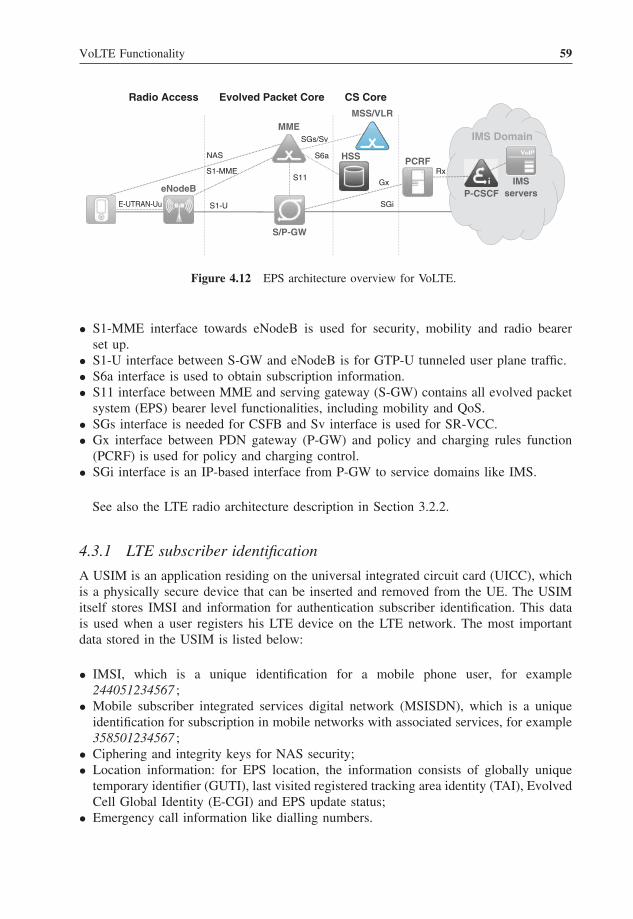
VoLTE Functionality 59
Radio Access
S/P-GW
MME
HSS
eNodeB
PCRF
IMS Domain
MSS/VLR
P-CSCF
CS CoreEvolved Packet Core
S1-MME
S1-UE-UTRAN-Uu
S11
S6a
Gx
SGi
RxIMS
servers
NAS
SGs/Sv
Figure 4.12 EPS architecture overview for VoLTE.
• S1-MME interface towards eNodeB is used for security, mobility and radio bearerset up.
• S1-U interface between S-GW and eNodeB is for GTP-U tunneled user plane traffic.• S6a interface is used to obtain subscription information.• S11 interface between MME and serving gateway (S-GW) contains all evolved packet
system (EPS) bearer level functionalities, including mobility and QoS.• SGs interface is needed for CSFB and Sv interface is used for SR-VCC.• Gx interface between PDN gateway (P-GW) and policy and charging rules function
(PCRF) is used for policy and charging control.• SGi interface is an IP-based interface from P-GW to service domains like IMS.
See also the LTE radio architecture description in Section 3.2.2.
4.3.1 LTE subscriber identification
A USIM is an application residing on the universal integrated circuit card (UICC), whichis a physically secure device that can be inserted and removed from the UE. The USIMitself stores IMSI and information for authentication subscriber identification. This datais used when a user registers his LTE device on the LTE network. The most importantdata stored in the USIM is listed below:
• IMSI, which is a unique identification for a mobile phone user, for example244051234567 ;
• Mobile subscriber integrated services digital network (MSISDN), which is a uniqueidentification for subscription in mobile networks with associated services, for example358501234567 ;
• Ciphering and integrity keys for NAS security;• Location information: for EPS location, the information consists of globally unique
temporary identifier (GUTI), last visited registered tracking area identity (TAI), EvolvedCell Global Identity (E-CGI) and EPS update status;
• Emergency call information like dialling numbers.

60 Voice over LTE
Figure 4.13 VoLTE traffic handling over EPS network.
The USIM also stores other network specific data such as SMS information, callinformation and public land mobile network (PLMN) information. More information isavailable in (3GPP TS 31.102).
4.3.2 PDN Connectivity Establishment for the VoLTE User
As described in Section 3.3 the LTE user has at least one PDN connection when the useris registered into the EPS network. For the VoLTE user the PDN connection is alwaysestablished to the well known IMS access point name (APN). The default bearer mustbe created during the initial attachment for IMS signalling and the dedicated bearer forthe media is created during the IMS voice call session setup. Figure 4.13 explains howsession initiation protocol/XML configuration access protocol SIP signalling and real-timetransport protocol/RTP control protocol (RTP/RTCP) media traffic is transferred over theLTE/EPC when a user has both IMS registration and an ongoing IMS voice call.
As shown in Figure 4.14 there are two bearers needed for VoLTE; the default bearerthat is created during the EPS registration and the dedicated bearer that is created duringthe voice call setup. The section below further explains the EPC functionalities neededfor the user registration and bearers establishment, first for IMS signalling and later forthe IMS voice call. IMS procedures are explained in Section 5.
4.3.2.1 EPS Registration
When a user switches his mobile phone on, the UE makes a registration via an initialattachment to the network. In the registration the user is authenticated, authorised and thesecurity association is created for the EPS signalling and user plane.
The user is authenticated based on the EPS authentication and key agreement (AKA)using the IMSI/P-TMSI (temporary mobile subscriber identity) and K that is a permanent

VoLTE Functionality 61
Radio setup
S/P-GWeNodeB MME HSS PCRF
EPS registration
EPS default bearer setup
VoLTEsupport
discovery
Radio bearer setup
P-CSCF
IMS registration
EPS dedicated bearer setup
IMS VoIP session setup
IMS VoIP session and dedicated bearer release
Figure 4.14 EPS and IMS procedure steps for the VoLTE user.
key stored on the USIM and in the authentication centre (AuC). After the authenticationthe network creates security context between UE and network. Note, the USIMapplication on a UICC is used for accessing an evolved UMTS terrestrial radio accessnetwork (E-UTRAN); subscriber identity module (SIM) application on a UICC is notsupported.
For the EPS there are two levels of security association between the UE and thenetwork, one between the UE and eNodeB and another between the UE and MME(Figure 4.15). The NAS security association provides integrity, protection and encryp-tion of NAS signalling using the key hierarchy presented below. The home subscriberserver (HSS) provides the security key Kasme from which the MME derives the securitykeys for NAS ciphering and integrity protection. For the radio interface there is integrityprotection for signalling and ciphering for the signalling and the user plane.
This provides a secure IP connection for VoLTE traffic. After security associationsare created, the MME updates the subscriber’s location to HSS, which responds withstored subscription data. The IMSI is the prime key to the subscription profile stored inthe HSS. The EPS subscription profile contains several parameters like IMSI, MSISDN,MME identity and at least one PDN subscription context.
For a VoLTE subscriber the subscription data contains a specific PDN subscriptioncontext, which defines default values for the IMS signalling bearer that carries SIPtraffic. Table 4.2 gives an example of PDN subscription context for the VoLTEuser.

62 Voice over LTE
UE eNB
HSS/AAACK, IK
USIMAUC
MME
K_ASME
Root KeyRoot Key
CK, IK
NAS Keys
AS Keys
UP Keys
Subscriber Authentication/Authorisation (AKA)
NAS Security Association
AS Security Association
AS Keys
NAS Keys
UP Security Association
UP Keys
Figure 4.15 EPS security key hierarchy and security associations.
4.3.2.2 EPS Default Bearer Setup
For each PDN connection at least one bearer is created, called the default bearer. For aVoLTE user the default bearer carries all control plane (signalling) traffic coming to/fromthe IMS APN. When a default bearer is created the P-GW allocates IP address(es) for thePDN connection. The default bearer parameters come from the HSS PDN subscriptioncontext presented in Table 4.2. Figure 4.16 shows an example of default bearer setup withrelated IP address and QoS information.
In the figure 4.6, the P-GW makes the IP address allocation for both Internet protocolversion (IPv)4 and IPv6 address types. The IPv6 capable UE must request the IPv4v6PDN type but the network may provide IPv4, IPv6 or both IPv4 and IPv6 addresses. Inthe default bearer creation the network provides a full IPv4 address and a globally unique/64 IPv6 prefix, and the UE constructs a full IPv6 address via an IPv6 stateless addressautoconfiguration.
The P-GW also sends a proxy call session control function (P-CSCF) address in thePDN connectivity response that is signalled to the UE. The UE shall indicate the requestfor a P-CSCF address to the network within the protocol configuration options (PCO)information element of the PDN connectivity request message. The network may provide
PDN connection
Default bearerIMS APN
QCI 5ARP 9APN-AMBR-UL 0.5MbpsAPN-AMBR-DL 1Mbps
IPv4 address 192.168.10.10IPv6 address 5555::a:b:c:d
Figure 4.16 Example of default bearer configuration.

VoLTE Functionality 63
Table 4.2 PDN subscription context
Parameter Purpose Example value
Context identifier Index of the PDN subscription context 5PDN type Indicates the subscribed PDN Type
(IPv4, IPv6, IPv4v6), that is whetherIPv4, IPv6 or both addresses areallocated to UE
2 (IPv4v6)
Service-Selection(Access pointname)
A label according to DNS namingconventions describing the accesspoint to the packet data network, thatis APN network identifier
IMS
EPS subscribedQoS profile
The bearer level QoS parameter valuesfor that APNs default bearer includingQCI and ARP (priority andpre-emption)
5 (QCI 5)9 (priority-level)1(pre-emption_capability_disabled)0 (pre-emption_vulnerability_enabled)
SubscribedAPN-AMBR
The maximum aggregated uplink anddownlink MBR to be shared across allNon-GBR bearers, which areestablished for this APN. Maximumbandwidth is in bits per second and itcontains all the overhead coming fromthe IP-layer and the layers above, forexample IP, UDP, RTP and RTPpayload
500 000 (max-requested-bandwidth-UL)1 000 000(max-requested-bandwidth-DL)
VPLMN addressallowed
Specifies whether for this APN the UE isallowed to use the PDN GW in thevisited operator network; for VoLTEroaming this must be enabled becauseP-GW is selected always from thevisited PLMN
1 (allowed)
APN-AMBR – APN-aggregate maximum bit rate, MBR – maximum bit rate, DL – downlink,VPLMN – visited PLMN.
a list of P-CSCF IPv4 or IPv6 addresses and the UE must prefer to the IPv6 address typewhen it discovers the P-CSCF.
The P-GW makes also bearer authorisation during the PDN connection establishment.Figure 4.17 describes signalling where P-GW gets PDN connectivity request with defaultEPS bearer parameters. The PDN connection establishment is done to the IMS APN,which means that the PDN GW is responsible to establish diameter session towards thePCRF over the Gx interface. The request to the PCRF contains at least the user identifica-tion, UEs Ipv4 address and/or Ipv6 prefix, Internet protocol-connectivity access network(IP-CAN) type and radio access type. The request may include also other information likethe UE time zone and PDN information. The PCRF may ask subscriber specific infor-mation from the subscription profile repository (SPR), or the PCRF may use the samerule set for all subscribers, for example on an APN basis. During the PDN connectionestablishment the PCRF may provide policy and charging control (PCC) rules, bearer

64 Voice over LTE
Online/OfflineCharging
SubscriptionRepository (SPR)
IMSServices
Access
PDN GW
PCRF
Figure 4.17 PDN connection policy and charging control authorisation.
authorisation and QoS parameters for the PDN connection (IP-CAN session) including anon-GBR, QCI and allocation and retention priority (ARP). More important is that PCRFknows the user’s identification and there exists a diameter session, which can be used fordynamic PCC during voice call establishment.
At the same time PDN GW may also connect to a charging system to make propercharging for the user’s PDN connection. Because VoLTE signalling and media goes overthe IMS APN it is enough to have APN-based charging with a related charging ID.
As part of the default bearer establishment the MME requests also radio access bearer(RAB) establishment. The MME sends bearer parameters to eNodeB to create radio bearerbetween UE and eNodeB, as shown in Section 4.2.1.
4.3.2.3 IMS Based VoIP Support Discovery
When the VoLTE UE makes an initial attachment it indicates its voice domain preference(preferring IMS PS voice over CS voice or only PS voice capable), usage settings (voicecentric or data centric) and SR-VCC capability.
The MME uses the UE provided information, local policy,1 home network capability,subscription information and the SR-VCC capability of the network to decide whetherIMS-based VoIP service can be provided. This decision is signalled back to the UE in theattach accept message using a dedicated parameter (IMS voice over PS session). Whenthe MME has set this indication value equal to true then the UE will realise that thenetwork supports IMS based VoIP and it will initiate IMS registration in order to initiateand receive VoIP communication as described in Section 5.4. If a MME signals that theIMS based VoIP is not available, then the VoLTE UE (as it is voice centric) will attemptCSFB attachment or it will move to UMTS terrestrial radio access network (UTRAN) orGERAN in order to obtain access to voice service.
Although 3GPP specifications do not specify conditions on the network side, whichleads to setting the IMS voice over PS session to true or false, the typical decision logicin the MME to set IMS voice over PS session to true is expected to be as follows:
1 The MME may check, for example based on mobile country code and mobile network code, whether local MMEpolicy would allow this home public land mobile network’s (HPLMN’s) roamer to have IMS VoLTE.

VoLTE Functionality 65
• UE provided information:– UE’s usage setting = voice centric;– Voice domain preference for E-UTRAN = IMS PS voice preferred, CS voice as
secondary;– SR-VCC supported (SR-VCC to GERAN/UTRAN capability = SR-VCC from
UTRAN HSPA or E-UTRAN to GERAN/UTRAN supported).• Information available in the network:
– Existing tracking area (TA) supports IMS VoIP;– Network supports SR-VCC and subscription information contains SR-VCC related
routing number.
The IMS VoIP indication can be set per TAI or per list of TAIs, and the indicationvalue may change when the UE moves to a new TA.
4.3.3 EPS Dedicated Bearer Setup
The dedicated EPS bearer is needed for voice media because default bearer QoS is notenough. 3GPP has defined the policy and charging control architecture, which is a linkbetween EPC and IMS domains. The policy and charging control is mandatory for IMSvoice sessions because the bearer level QoS is based on the IMS voice media sessioninformation that is negotiated for each voice call dynamically.
For the voice call the PCRF gets voice session information from the P-CSCF and,based on that information, the PCRF makes QoS provisioning towards P-GW. The PCRFalso informs P-CSCF of a bearer level event, for example if QoS cannot be guaranteedor if there is loss of PDN connectivity. The P-GW decides, based on the QCI and ARPpair, that a new dedicated bearer has to be established to provide the required QoS for thevoice media. The P-GW initiates dedicated bearer signalling towards access and informsthe PCRF after successful establishment.
The dedicated bearer shares the very same IP address(es) as the default bearer but ithas a different QoS. For the IMS voice media the dedicated bearer is always GBR, whichmeans that voice media can be guaranteed, or if not then the IMS voice call must bereleased.
The traffic differentiation is done based on the flow information and P-GW generates atraffic flow template to mobile that the mobile can do a proper bearer selection for uplinktraffic.
Figure 4.18 depicts an example of one default bearer with default QoS and one dedicatedbearer with QoS applicable for IMS voice media.
4.4 IMS Identification
This section introduces ISIM and different identifiers that are used to identify a user(public user identity), the user’s subscription (private user identity), the user’s device anda public user identity combination [globally routable user agent URI (GRUU)], the service(public service identity) and IMS network entities. In addition the relationship betweendifferent user identities is explained.

66 Voice over LTE
Dedicated bearer
Default bearerIMS APN
QCI 1ARP 9GBR=MBR 32kbpsTFT
QCI 5ARP 9APN-AMBR-UL 0.5MbpsAPN-AMBR-DL 1.0Mbps
IPv4 address 192.168.10.10IPv6 address 5555::a:b:c:d
Figure 4.18 Example of default and dedicated bearer configuration.
4.4.1 IP Multimedia Services Identity Module
An ISIM is an application residing on the UICC, which is a physically secure device thatcan be inserted into and removed from the UE. There may be one or more applications inthe UICC, for example USIM and ISIM. The ISIM itself stores IMS-specific subscriberdata mainly provisioned by an IMS communication service provider. This data is mainlyused when a user registers a device to the IMS. The following data can be stored inISIM, for example when a user obtains an IMS subscription from a communicationservice provider:
• Private user identity of the user – this is used in a registration request to identify theuser’s subscription (see Section 4.4.3 for further information);
• One or more public user identities of the user – this is used in a registration request toidentify an identity to be registered and is used to request communication with otherusers (see Section 4.4.2 for further information);
• Security parameters related to authentication to IMS (such as shared secret and sequencenumber) and generic bootstrapping architecture (required for Ut authentication, forexample for reading/modifying supplementary service settings);
• SMS parameters required for IMS-based messaging;• List of IMS application reference identifiers which can be used as indicated in IMS
registration;• Address of P-CSCF – this can be used when the access technology does not support
dynamic P-CSCF discovery capabilities (not applicable for LTE);• The name of the entry point of the home network (home network domain name) – this
is used in a registration request to route the request to the user’s home network;• Administrative data includes various data which could be used, say, by IMS subscribers
for IMS operations or by manufacturers to execute proprietary auto-tests;• Access rule reference – this is used to store information about which personal identi-
fication number needs to be verified in order to get access to the application.
Originally it was assumed that IMS capable devices must be equipped with ISIM butthis requirement has been relaxed and currently mobile communication service providersare dominantly allowing access to the IMS with devices equipped with SIM or USIMcards. As EPC access requires the use of USIM, the VoLTE requirement is therefore thatthe UICC inside the VoLTE UE is equipped either with USIM or with USIM + ISIM.

VoLTE Functionality 67
VoLTE operation is possible just without ISIM as 3GPP has defined how the IMS UEcan generate IMS identifiers and home domain name out of data stored in USIM (seeSection 4.4.8).
4.4.2 Public User Identity
User identities in IMS networks are called public user identities. They are the identitiesused for requesting communication with other users. Public identities can be published(e.g. in phone books, Web pages, business cards). IMS users will be able to initiate ses-sions and receive sessions from many different networks, such as GSM networks andthe Internet. To be reachable from the CS side, the public user identity must conformto telecom numbering (e.g. +358501234567). In similar manner, requesting communi-cation with Internet clients, the public user identity must conform to Internet naming(e.g. [email protected]). The tel universal resource locator (URL) scheme is used toexpress traditional E.164 numbers in URL syntax. The tel URL is described in (RFC3966),and the SIP uniform resource identifier (URI) is described in (RFC3261) and (RFC3986).User needs to register public user identity (see Section 5.4) before the identity can beused to originating and terminating IMS communication. It is possible to register multiplepublic user identities through one single UE and even multiple identities through singleUE request (see Section 5.4.8). Examples of public user identities are given below.
Example of SIP URI sip:[email protected] of tel URL tel:+358501234567
4.4.3 Private User Identity
The private user identity is a unique global identity defined by the home network com-munication service provider, which may be used within the home network to uniquelyidentify the user from a network perspective (3GPP TS 23.228). It does not identify theuser herself; on the contrary, it identifies the user’s subscription. The private user identityis contained in all registration requests passed from the UE to the home network (seeSections 5.4.1 and 5.4.8) and is authenticated during registration of the user. The privateuser identity is not used for the routing of SIP messages and it is not present at all in IMSsessions (INVITE) and IMS session-unrelated procedures (e.g. MESSAGE, SUBSCRIBE,NOTIFY). In addition to authentication purposes the private user identities can be usedfor accounting and administration purposes as well. The private user identity takes theform of a network access identifier (NAI) defined in (RFC2486). An example of privateuser identity is given below.
Example of NAI [email protected]
4.4.4 Relationship between Private and Public User Identities
Here is a basic example to show how different identities are linked to each other. Inthis example Joe is working for a car sales company and is using a single device for

68 Voice over LTE
IMSSubscription
PrivateUser Identity1
tel: + 358501234567
tel: + 358503334444
ServiceProfile 1
ServiceProfile 2
Figure 4.19 Relationship of user identities.
both his work life and his personal life. To handle work-related matters he has twopublic user identities: sip:[email protected] and tel: +358501234567. Whenhe is off duty he uses two additional public user identities to manage his personal life:sip:[email protected] and tel: +358503334444. By having two sets of pub-lic user identities he can have a totally different treatment for incoming sessions: forexample he is able to direct all incoming work-related sessions to a messaging systemafter 5 p.m. and during weekends and holidays. Joe’s user and service-related data aremaintained in two different service profiles (see also Figure 4.19). One service profilecontains information about his work life identities and is downloaded to the serving callsession control function (S-CSCF) from the HSS when needed: that is when Joe regis-ters a work life public user identity or when the S-CSCF needs to execute unregisteredservices for a work life public user identity. Similarly, another service profile containsinformation about his personal life identities and is downloaded to the S-CSCF fromthe HSS when needed. Figure 4.19 shows how Joe’s private user identity, public useridentities and service profiles are linked together.
IMS also supports more advanced use cases where Joe could have more than one device.So in addition to the identities listed in the previous example Joe could have one additionalidentity sip:[email protected] that is shared to all his devices. It means that when someoneuses this shared identity to initiate communication Joe can accept the incoming commu-nication with any of his registered devices. According to IMS architecture a shared publicused identity must be shared with all private user identities within the IMS subscription(3GPP TS 23.228). Figure 4.20 depicts this configuration (sip:[email protected] could alsopoint to its own service profile if desired; here it is linked to service profile number 2).
4.4.5 Identification of User’s Device
In the IMS public user identities are used to reach the recipient and single public useridentity can be shared among a number of devices under a single subscription. Thismeans that it is not possible to identify a specific device when more than one device hasbeen registered with the same public user identity. To reach a particular device a specificidentifier called a globally routable user agent URI (GRUU) must be used. For exampleuser Joe has a shared public user identity and if his presence status indicates that he is

VoLTE Functionality 69
IMSSubscription
PrivateUser Identity1
PrivateUser Identity2
tel: + 358501234567
tel: + 358503334444
ServiceProfile 1
ServiceProfile 2
Figure 4.20 Relationship of user identities including shared identity.
UE-1
UE-2
Device Identifier 2
Device Identifier 1
GRUU-1
GRUU-2
GRUU-3
GRUU-4
Public UserIdentity 1
Public UserIdentity 2
Public UserIdentity 3
Figure 4.21 Relationship between UE, GRUU and public user identities.
willing to play games with UE1 and that he is willing to accept a video session with UE2then the GRUU of UE1 (GRUU2 in Figure 4.21) can be used to establish a game sessionwith Joe. Another typical use case for GRUU usage is session transfer from one deviceto another particular device. Figure 4.21 shows the relationship between UE, GRUU andpublic user identity.
Two types of GRUU are defined: temporary GRUU and public GRUU. Public GRUU inIMS is a combination of user’s public user identity and identifier of the device from whichthe public user identity is registered to the IMS. The purpose of public GRUU is to enablelong lived capability to reach a particular device as it remains the same as long as publicuser identity–device pair exists. In contrast, temporary GRUU is an identifier that has alimited life time (a new temporary GRUU is created in each IMS registration request) andit keeps the user’s public user identity hidden, that is it does not contain the user’s publicuser identity at all. In the example below sip:[email protected] is the user’s public user

70 Voice over LTE
identity; ‘gr’ is URI parameter indicating that this SIP URI is actually GRUU, ‘urn:uuid’is a uniform resource name (URN) that uniquely identifies this specific device wheref81d4fae-7dec-11d0-a765-00a0c91e6bf6 is the unique value identifying particular device.
Example of public GRUU sip:[email protected]; gr = urn:uuid:f81d4fae-7dec-11d0-a765-00a0c91e6bf6
Example of temporary GRUU sip:tgruu.7hs == [email protected];gr
4.4.6 Identification of Network Entities
In addition to users, network nodes that handle SIP routing need to be identifiable usinga valid SIP URI. These SIP URIs would be used when identifying these nodes in theheader fields of SIP messages. However, this does not require that these URIs be globallypublished in a domain name system (DNS), see (3GPP TS 23.228). A communicationservice provider could name its S-CSCF as follows:
Example of network entity naming sip:[email protected]
4.4.7 Identification of Services (Public Service Identities)
With the introduction of standardised presence, messaging, conferencing and group servicecapabilities it became evident that there must be identities to identify services and groupsthat are hosted by application servers (ASs). Identities for these purposes are also createdon the fly: that is they may be created by the user on an as-needed basis in the ASand are not registered prior to usage. Ordinary public user identities were simply notgood enough; so, Release 6 introduced a new type of identity, the public service identity.Public service identities either take the form of a SIP URI or are in tel URL format.Section 4.6.3.6 shows an example use case where user creates an ad-hoc conferenceusing a public service identity (conference factory URI) and an AS further shares thedynamic public service identity as a conference URI.
4.4.8 Identification Without ISIM
Sections 4.4.2 and 4.4.3 explained the concepts of public user identity and private useridentity. It was assumed that these identities are stored in an ISIM application. Whenthe IMS is deployed there is a number of UE in the market place that are not equippedwith the ISIM application; therefore, a mechanism to access the IMS without the ISIMwas developed. In this model, private user identity, public user identity and home domainname are derived from an IMSI. This mechanism is suitable for UE that has a USIMapplication.
4.4.8.1 Derived Private User Identity
The private user identity derived from the IMSI is built according to the following steps(3GPP TS 23.003):

VoLTE Functionality 71
1. Use the whole string of digits as the username part of the private user identity.2. Form the domain part of private user identity by using predefined syntax,
ims.mnc.mcc.3gppnetwork.org, where MNC and MCC are extracted from IMSI (firstthree leading digits identifies MCC and next 2 or 3 digits identifies MNC).2
For example:
IMSI in use: 244911234567; where:MCC: 244;MNC: 91;MSIN: 1234567; andPrivate user identity is:[email protected]
4.4.8.2 Temporary Public User Identity
If there is no ISIM application to host the public user identity, a temporary public useridentity will be derived, based on the IMSI. The temporary public user identity will takethe form of a SIP URI, ‘sip:user@domain’. The user and domain part are derived similarlyfrom the method used for private user identity (3GPP TS 23.003). Following our earlierexample a corresponding temporary public user identity would be:
When a temporary public user identity is used in an IMS initial registration it is placedin To and From headers (see Section 5.4.1). A valid IMS public user identity will beimplicitly registered and the S-CSCF will deliver it to the UE (in P-Associated-URIheader) when it accepts the registration (see Section 5.4.8). After the initial registration,the UE will only use the implicitly registered public user identity(s). It is strongly recom-mended that the temporary public user identity is set to ‘barred’ for IMS non-registrationprocedures so that it cannot be used for IMS communication.
4.4.8.3 Home Network Domain Name
A home network domain name is derived in the same way as the domain part of temporaryprivate user identity. So in our example it would be:
ims.mnc091.mcc244.3gppnetwork.org
4.5 IMS Service Provisioning
Strictly speaking the IMS is not a service in itself; on the contrary, it is a SIP-basedarchitecture for enabling an advanced IP service and application on top of the PS network.IMS provides the necessary means for invoking services; this functionality is called hereas ‘service provisioning’. Figure 4.22 gives an overview of service provisioning.
2 If the MNC is two digits then a zero shall be added at the beginning to make it three digits long.

72 Voice over LTE
S-CSCF
HSS AS
• Downloads/receives service profile• Enforces allowed services based onservice profile information• Routes requests to AS based onservice triggering information
• Stores service profile• Stores data uploaded by AS
• Executes services• Downloads/receives user data• Stores application data inHSS or itself
Sh
ISCCx
Figure 4.22 IMS service provisioning overview.
The HSS as a master database contains permanently user’s IMS subscription informa-tion and one part of this information is IMS service profile (see also Section 5.2 andespecially Figure 5.2). In addition may act as a permanent storage for application specificdata uploaded by AS. This data may also contain such data which is not understoodsemantically by the HSS.
4.5.1 Enforcement of Allowed Services
While serving a user, the S-CSCF uses the downloaded service profile to enforce allowedservices based on the configured media policy and IMS communication service identifierpolicy.
• Media policy information contains an integer that identifies a subscribed media profilein the S-CSCF (e.g. allowed session description protocol (SDP) parameters). This infor-mation allows communication service providers to define different subscriber profilesin their IMS networks. They may define different customer classes, such as gold, silverand bronze. Gold could mean that a user is able to make video calls and all ordinarycalls. Silver could mean that a user is able to use wideband adaptive multi-rate (AMR)as a speech codec, but they are not allowed to make video calls and so on. Transferringjust the integer value between the HSS and the S-CSCF saves the storage space in theHSS and optimises the usage of the Cx reference point.
• IMS communication service identifier policy contains a list of service identifiers thatidentifies which IMS communication service user is entitled to use, for example IMSMMTel. Based on the provided list the S-CSCF enforces usage of identifiers in SIPsignalling.

VoLTE Functionality 73
4.5.2 Service-Triggering Information
Service-triggering information is presented in the form of initial filter criteria (seeFigure 4.23). The initial filter criteria describe when an incoming SIP message isfurther routed to a specific AS. The service profile may contain both user-specificservice-triggering information which is coded as initial filter criteria and a referencevalue to initial filter criteria which are locally administrated and stored in S-CSCF. Thelatter is called shared initial filter criteria and it is encoded as an integer value wherethe integer value only has a meaning inside a single communication service provider’snetwork. For example, value 1 could point triggers that take care of routing requests toopen mobile alliance (OMA) instant messaging (IM), push to talk over cellular (PoC),Presence and XML document management (XDM) applications, and value 2 could pointtriggers that take care of routing requests to IP centrex.
Whenever a user obtains a VoLTE subscription then it is fair to assume that her sub-scription will contain a number of voice supplementary services which are providedby a telephony application server (TAS) as described in Section 4.6.3. Therefore, a
Initial Filter Criteria
Priority
Service Point Trigger
Service Point Trigger
Request-URI
SIP Method
Service Point Trigger
Trigger Point
ProfilePartIndicator
Service Information 0..1
Application Server
ServerName
DefaultHandling
ServiceInfo
IncludeRegisterRequest 0..1
IncludeRegisterResponse 0..1
SIP Header
Session Case
Session Description
Figure 4.23 IMS initial filter criteria.

74 Voice over LTE
communication service provider needs to include initial filter criteria to her service profilewhich will ensure that S-CSCF routes both incoming and outgoing voice session to theTAS for service execution.
When constructing the initial filter criteria the communication service provider needsto consider these questions:
• What is the priority of an initial filter criterion?• What is a trigger point?• Is this initial filter criteria for a registered user or an unregistered user?• What is the correct AS when the trigger point is met?• What should be done if the AS is not responding?
The trigger point is used to decide whether an AS is contacted. It contains one tomultiple instances of a service point trigger, as shown in Figure 4.23. The service pointtrigger comprises these items:
• Request-URI – identifies a resource that the request is addressed to (e.g. [email protected]).
• SIP method – indicates the type of request (e.g. INVITE or MESSAGE).• SIP header – contains information related to the request. A service point trigger could
be based on the presence or absence of any SIP header or the content of any SIP header.The value of the content is a string that is interpreted as a regular expression. A regularexpression could be as simple as a proper noun (e.g. John) in the FROM header thatindicates the initiator of the request.
• Session case – can be any one of four possible values, originating, terminating, origi-nating unregistered or terminating unregistered, that indicate whether the filter shouldbe used by the S-CSCF that is handling the originating service, terminating service ororiginating/terminating for an unregistered end user service. An originating case refersto when the S-CSCF is serving the calling user. A terminating case refers to when theS-CSCF is serving the called user.
• Session description – defines a service point trigger for the content of any SDP fieldwithin the body of a SIP method. Regular expressions can be used to match the trigger.
If the trigger point is met then the initial filter criteria contain instructions on what to donext. These instructions contain the address of the AS, what to do if contact with the ASfails (either terminate or allow session to proceed) and may contain further instructionsto the S-CSCF when the initial filter criterion is set for IMS registration (i.e. pass serviceinformation received from HSS to AS, deliver REGISTER request from UE to AS andpass 200 OK (of REGISTER) request to the AS).
A user may have more than one initial filter criteria in her service profile thereforecommunication service profile needs to assign an unique priority number for each initialfilter criteria. The higher the priority number the lower the priority of the filter criteria is;that is a filter criteria with a higher value of priority number shall be assessed after thefilter criteria with a smaller priority number have been assessed.
Each initial filter criteria contains an attribute, ProfilePartIndicator, which tellswhether particular initial filter criteria is to applied when the user is either registered orunregistered.

VoLTE Functionality 75
4.5.3 Selection of AS
The S-CSCF assesses the filter criteria for the initial request alone, according to thefollowing steps (3GPP TS 24.229):
1. Check whether the public user identity is barred; if not, then proceed.2. Check whether this request is an originating request or a terminating request.3. Select the initial filter criteria for a session case (originating, terminating or originat-
ing/terminating for an unregistered end user).4. Check whether this request matches the initial filter criterion that has the highest
priority for that user by comparing the service profile with the public user identity thatwas used to place this request:a. If this request matches the initial filter criterion, then the S-CSCF will forward this
request to that AS, check to see whether it matches the next following filter criterionof lower priority and apply the filter criteria on the SIP method received from thepreviously contacted AS.
b. If this request does not match the highest priority initial filter criterion, then checkto see whether it matches the following filter criterion’s priorities until one doesmatch.
c. If no more (or none) of the initial filter criteria apply, then the S-CSCF will forwardthis request based on the route decision.
There exists one clear difference in how the S-CSCF handles the originating and ter-minating initial filter criteria. When the S-CSCF realises that an AS has changed theRequest-URI in the case of terminating initial filter criteria it has three options:
• Route the request based on the changed value of the Request-URI;• Use and execute the initial filter criteria for the UE-originating case after retargeting;• Continue to use the initial filter criteria for the UE terminating case.
In an originating case the S-CSCF will continue to evaluate initial filter criteria untilall of them have been evaluated.
If the contacted AS does not respond, then the S-CSCF follows the default-handlingprocedure associated with initial filter criteria: that is either terminate the session or let thesession continue, based on the information in the filter criteria. If the initial filter criteriado not contain instructions to the S-CSCF regarding the failure to contact the AS, thenthe S-CSCF will let the call continue as the default behaviour (3GPP TS 24.229).
4.5.4 AS Behaviour
4.5.4.1 Service Execution
Section 4.5.3 described how the request is routed to an AS. After receiving the request theAS initiates the actual service. To carry the service out the AS may act in four differentmodes:
• Terminating user agent (UA) – the AS acts as the UE. This mode could be used, forexample to provide a voice mail service.

76 Voice over LTE
• Redirect server – the AS informs the originator about the user’s new location or aboutalternative services that might be able to satisfy the session.
• SIP proxy – the AS processes the request and then proxies the request back to theS-CSCF. While processing, the AS may add, remove or modify the header contentscontained in the SIP request according to the proxy rules specified in (RFC3261).
• Third-party call control/back to back UA – the AS generates a new SIP request for adifferent SIP dialogue, which it sends to the S-CSCF. This could be, for example TASproviding an ad-hoc multi party conference (see Section 4.6.3.6).
In addition to these modes, an AS can act as an originating UA. When the applicationis acting as an originating UA it is able to send requests to the users: for example aconferencing server may send SIP INVITE requests to a pre-defined number of people at9 a.m. for setting up a conference call. Another example could be a news server sending aSIP MESSAGE to a soccer fan to let him know that his favourite team has scored a goal.
4.5.4.2 User and Service Specific Data
There are different sources where the AS can receive user- and service-specific data.Users can utilise the Ut reference point (see Figure 3.18) to store application specific datain the AS, for example supplementary service data (see Section 4.6.3.11). A communi-cation service provider can use operation and management tools to configure informationto the AS. The AS can use the Sh reference point (see Figure 3.18) to store data inthe HSS to support its service logic. Via the Sh reference point the AS can also down-load and receive all kinds of data available in the HSS or available via the HSS. Thisinformation contains, for example IMS registration status, CS/PS network [MSC, MME,serving GPRS support node (SGSN)] status, public user identities, initial filter criteria,the S-CSCF name serving the user, addresses of the charging functions, UE IP addressinformation, the UE’s SR-VCC capability information, CS domain routing number, infor-mation which radio access type (e.g. E-UTRAN) is serving the UE and whether or notIMS voice over the PS session is supported at the current geographic area where the UEis currently located, session transfer number for SR-VCC, Internet protocol short messagegateway (IP-SM-GW) number and even location information from the CS and PS domains(3GPP TS 29.329).
4.5.5 Service Provisioning in Action
Figure 4.24 summarises the service provisioning in action. In step 1 either the originatingor terminating request arrives at the S-CSCF. If the S-CSCF is serving an unregistereduser and the service profile(s) is(are) not already available then the S-CSCF downloadsthe profile in step 2. In step 3 the S-CSCF executes enforcement of the allowed servicesas described in Section 4.5.1 and evaluates the initial filter criteria. As an outcome ofmatching initial filter criterion the request is forwarded to the AS for service execution(step 4). The AS may retrieve additional information from the HSS (step 5) as describedin Section 4.5.4.2 and the AS executes the service in step 6. In step 7 the outcome of exe-cution is communicated back to the S-CSCF. Depending on result of service execution the

VoLTE Functionality 77
S-CSCF
HSS AS
1. Incomingrequest
2. Service profile(s)dowloaded
(not required for registered user)
3. Assessment ofservice information
7. Request terminated/returned/new request is created
5. Retrieval of user/service data(if not done earlier)
6. Serviceexecution
0. Serviceconfiguration
4. Requestforwarded
8a. Outgoingrequest
8b. Response
Figure 4.24 IMS service execution overview.
S-CSCF executes the next steps (continue initial filter criteria evaluation, route requestforward or pass response back to requestor).
For a VoLTE subscriber, a communication service provider needs to create at least someinitial filter criteria to make sure that all voice sessions gets routed to TAS and SMS overIP messages are correctly delivered to the IP-SM-GW. Table 4.3 shows the basic requiredinitial filter criteria settings for VoLTE user. The first two criteria are required to cover
Table 4.3 VoLTE initial filter criteria examples
Element of Filter Filter Filter Filterfilter criteria criterion 1 criterion 2 criterion 3 criterion 4
SPT: SIP method Invite Invite Invite MessageSPT: Session case Terminating Terminating Originating OriginatingFurther SPT Session
description:m = audio
Sessiondescription:m = audio
Sessiondescription:m = audio
SIP header: content-type:application/vnd.3gpp.smsRequest-URI:+358508888888
Application server sip:[email protected]
Priority 1 2 3 4Profile part
indicatorRegistered Unregistered Registered Registered
SPT – Service point trigger.

78 Voice over LTE
mobile terminating voice sessions. The third criterion is used to make sure that VoLTEuser initiated voice sessions will receive originating voice services. The fourth criterionis set to ensure that SMS over IP messages are interworking at the originating networkand not passed towards remote networks which may not have messaging interworkingtechnology in place.
To complete IMS service provision let us verify that the above filter criteria 1 and 3work for our example VoLTE user, Kristiina (see Section 5.1).
4.5.5.1 Terminating VoLTE Session
When Kristiina receives a request to engage on voice communication her S-CSCF willreceive a SIP INVITE targeted to her. The INVITE will contain among other thingsfollowing key pieces of information:
INVITE sip:[email protected] SIP/2.0P-Asserted-Identity:sip:[email protected]:<sip:scscf1.example.com;lr>Content-Type: application/sdpm=audio 3420 RTP/AVP 97 98
The S-CSCF detects that the filter criterion 1 matches, because:
• The SIP method is INVITE.• The INVITE request is targeted to the terminating user – the S-CSCF knows this based
on the content of the Route header. It does not contain the value which was communi-cated in the Service-Route header during the registration to the UE and P-CSCF (seeSection 5.4.8).
• The SDP payload contains a dedicated line stating that this request is for audio com-munication.
• Kristiina is registered.
4.5.5.2 Originating VoLTE Session
When Kristiina wants to engage in voice communication her UE will send a SIP INVITEto the network as described in detail in Section 5.5. This invite will find its way to theS-CSCF serving Kristiina. Among other things, the INVITE will contain the followingkey pieces of information:
INVITE sip:[email protected] SIP/2.0P-Asserted-Identity: sip:[email protected]:<sip:[email protected];lr>Content-Type: application/sdpm=audio 3458 RTP/AVP 97 98
The S-CSCF detects that filter criterion 3 matches, because:
• The SIP method is INVITE.

VoLTE Functionality 79
• The INVITE request is received from the originating user – the S-CSCF knows thisfrom the user part it set in its Service-Route header entry (see Section 5.5.8) and whichis now returned in the Route header.
• The SDP payload contains a dedicated line stating that this request is for audio com-munication.
• Kristiina is registered.
4.6 IMS Multimedia Telephony
4.6.1 Introduction
The MMTel is a blended standardised multimedia service suite in the IMS and providessupport for mobile as well as for fixed users. The MMTel service allows users to establishcommunications between them and enrich that communication by enabling supplementaryservices.
The IMS MMTel service consists of two principal parts:
• Basic communication (Section 4.6.2);• Optional supplementary services (Section 4.6.3).
The need for IMS supplementary services was discussed in 3GPP Release 5, and atthat time 3GPP decided that there was no need to standardise supplementary servicesas SIP protocol enables basic capabilities such as communication forwarding, identityservices and communication hold. After ETSI telecommunications and internet convergedservices and protocols for advanced networking (TISPAN) made a decision to use theIMS core network as a platform for their next generation network (NGN) they startedto define supplementary services for the IMS. The first set of supplementary serviceswas completed as part of TISPAN Release 1. In parallel 3GPP as part of the work on3GPP Release 7 defined the so-called IMS MMTel service which has reused some ofthe TISPAN supplementary services and made them available in general to the IMS. InTISPAN Release 2, TISPAN continued to work on supplementary services for IMS, butafter completion of TISPAN Release 2 the responsibility for all specifications relevant forIMS core network including the specifications for supplementary services was transferredfrom TISPAN to 3GPP as part of the effort on a common IMS (see also Section 3.4.2and Figure 4.25).
The One Voice initiative defined a profile for the IMS for voice and SMS which containsa minimum set of features to be supported by a cellular UE and an IMS network whichhas been published as GSM association (GSMA) PRD (IR.92). Part of the scope wasto define a subset of MMTel supplementary services and related capabilities so that atelephony service as known from 2G/3G networks can be built. The 3GPP Release 8 setof specifications for MMTel do not provide capabilities for the end user to manipulate thesupplementary service settings from both 2G/3G and MMTel UE in a consistent manner,that is it does not provide a capability to simulate the capabilities of the supplementaryservices as known from 2G/3G. In other words a 1 : 1 synchronisation between 2G/3Gsupplementary service settings and full blown IMS MMTel is not possible because MMTelcontains options which are not applicable in 2G/3G. It was recognised that this can

80 Voice over LTE
ETSI TISPAN R1/R2IMS-simulated PSTN/ISDN
Supplementary Services (SS)
2006: Referring to
3GPP Release 8/9/10MMTel Specifications
3GPP Release 7MMTel Specifications
BasicCommunication(voice, video…)
SS 1SS 2
….SS n
SS 1SS 2
….SS n
SS n+1
SS n+…
2008: Referring to
BasicCommunication(voice, video…)
GSMA IR.92GSM like Subset of SS
Single Option per SS Selected
BasicCommunication
(only voice)SS 1SS 2
SS 10
2010: Referring to
(2008: empty documents)
Figure 4.25 Supplementary services in TISPAN, 3GPP MMTel and GSMA (IR.92).
lead to an unwanted end user experience and a solution for this was specified in 3GPPRelease 9. In order to provide the possibility to profile the existing MMTel supplementaryservices and its options, the specifications for the impacted supplementary services andthe specification for XCAP over Ut (3GPP TS 24.623), were enhanced to allow the UEto get information about which supplementary services and which actions and conditionsfor a supplementary service are supported. This means that it is possible to build servicessuch that only those settings which can be mapped to the 2G/3G supplementary servicedata model are allowed and the UE is informed accordingly. As part of the solution, thenetwork can reject service modification requests which violate configuration limitationsin the network. The solution does not by any means limit already existing standardisedMMTel capabilities. It rather provides the possibility to define a profile of supplementaryservices like GSMA (IR.92).
4.6.2 Multimedia Communication
Typically MMTel is a service using speech and speech combined with other media compo-nents, but the service is not limited to always include speech, it also caters for other mediaor combinations of media (e.g. text and video). MMTel service includes the followingstandardised media capabilities:
• Full duplex speech;• Real time video (simplex, full duplex), synchronised with speech if present;• Text communication;• File transfer;• Video clip sharing, picture sharing, audio clip sharing; transferred files being dis-
played/replayed on the receiving terminal for specified file formats;• User datagram protocol (UDP) transport layer based transfer of fax.

VoLTE Functionality 81
Based on these capabilities different types of communication use cases could be realised,for example voice calls, voice call enriched with video (unidirectional or bidirectional),basic voice call enriched with sharing, basic voice call enriched with file transfer, basicvoice call enriched with video and text communication, basic voice call enriched withvideo and text communication and file transfer, text communication (chat), file transfermessage session relay protocol (MSRP), sharing (image, video). 3GPP has defined a ded-icated IMS communication service identifier (ICSI), 3gpp-service.ims.icsi.mmtel, whichUE adds to its IMS registration (see Section 5.4.1) and IMS session (see Section 5.5.1) toindicate that desired service is MMTel. For speech, video real-time text and fax 3GPP hasdefined rules for media encoding as summarised in Table 4.4 (3GPP TS 26.114). For filetransfer, sharing and chatting MSRP (RFC4975) is required. All codecs in Table 4.4 usethe RTP (RFC3550) over UDP and IP as transport. They apply specific payload formatswithin RTP, for example (RFC4867) for AMR and adaptive multi-rate wideband (AMR-WB). They also apply a so-called RTP profile, which is signalled in the SDP (RFC4566)as transport parameter. RTP/AVP(attribute value pair) (RFC3551) is the oldest such RTPprofile developed by IETF and in widespread use. RTP/AVPF (audio-visual profile withfeedback) (RFC4585) is an enhanced profile. Applicable codecs for media streams arenegotiated using SDP within SIP signalling and applying the offer-answer procedures (seeSection 5.4.3).
4.6.3 Supplementary Services
In order to provide supplementary services within the IMS, the IMS core network willinclude a Telephony Application Server (TAS) in the call chain. The TAS is a SIPapplication server that is connected via the IMS service control (ISC) interface and
Table 4.4 Codecs used for MMtel media
Media type 3GPP requirements (Release 10)
Speech AMR narrowband (NB) is mandatoryWideband (16 kHz sampling frequency) is optional. If
supported then AMR-WB is mandatory.DTMF support is mandatory.
Video ITU-T recommendation H.264/MPEG-4 (part 10)advanced video coding (AVC) 24 constrainedbaseline profile (CBP) level 1.2 is mandatory.
Real-time text ITU-T recommendation T.140Fax ITU-T recommendation T.38Media transport for speech,
video and textIn Rel-7 and Rel-8, support of RTP/AVP mandated
for all media types and support of RTP/AVPF ismandated for video and recommended for othermedia types.
In Rel-9 support of both RTP/AVPF and RTP/AVP ismandated for all media.
DTMF – Dual-tone multifrequency.

82 Voice over LTE
provides the network support for the supplementary services of MMTel. Depending onwhether the supplementary service applies to the originating or terminating side, a TASwill be included on the originating and/or terminating side network.
In addition to the use of SIP for call control of the supplementary services the TAS needsto provide a configuration interface to allow the user to configure its service settings. Viathis interface the user can configure the behaviour of some of the supplementary services.IMS has defined the following possibilities:
• Using XCAP via the Ut interface using;• Using SIP based user configuration.
Further it is possible to employ non standardised means to configure the behaviours ofsupplementary services, for example a Web-based interface.
Figure 4.26 shows the principle architecture and protocols used for MMTel. AP inFigure 4.26 stands for authentication proxy. It is a 3GPP function that takes care ofauthenticating the user when the user needs to send XCAP requests and it takes careof finding the right XCAP server (MMTel, IM, Presence, etc.) providing the requiredservice functionality.
Since the start of specifying MMTel in 3GPP Release 7, the list of supported supplemen-tary services in MMTel has grown with every 3GPP Release. Most of the supplementaryservices are similar to supplementary services specified for CS speech. Table 4.5 listsstandardised IMS supplementary services. The last column in Table 4.5 indicates whethera particular supplementary service is included in the GSMA (IR.92) IMS profile for voiceand SMS. In the following sections we describe the supplementary services which areincluded in GSMA (IR.92). GSMA (IR.92) includes additional restrictions for commu-nication diversion (CDIV) and communication barring services. These restrictions arecovered in Section 4.6.3.11.
4.6.3.1 Originating Identification Presentation
The public user identity is conveyed within three different headers within a SIP INVITErequest:
• The From header, which can be set to any value the calling user wants;• The P-Preferred-Identity header, in which the calling user can indicate one of its public
user identities, that is the identity that it wants to be used for the call;• The P-Asserted-Identity header, in which the authorised identity of the user is trans-
ported.
P-CSCF S-CSCF
HSS
TAS
SIP SIP
SIP
Diameter
XCAPAP
XCAP
Figure 4.26 Basic IMS architecture in support of multimedia telephony.

VoLTE Functionality 83
Table 4.5 IMS supplementary services
Supplementary service Description GSMA (IR.92)functionality
Release 7 baselineOriginating identification
presentation (OIP)Service provides the terminating user with
the identity of the originating userYes
Originating identificationrestriction (OIR)
Service enables the originating user toprevent presentation of its identityinformation to the terminating user
Yes
Terminatingidentificationpresentation (TIP)
Service provides the originating user withthe possibility of receiving identityinformation in order to identify theterminating user
Yes
Terminatingidentificationrestriction (TIR)
Service offered to the connected user whichenables the connected user to preventpresentation of the terminating identityinformation to the originating user
Yes
Communication hold(HOLD)
Service enables a user to suspend mediawithin a session, and resume that mediaat a later time
Yes
CONFerence calling(CONF)
Service enables a user to participate in andcontrol a simultaneous communicationinvolving a number of users
Yes
CommunicationDIVersion services(CDIV)
Service (aka communication forwarding)allows the user to re-direct an incomingrequest that fulfils certain provisioned orconfigured conditions to anotherdestination
Yes
Communication barring(CB)
Service allows users to selectively blocksession attempts
Yes
Message waitingindication (MWI)
Service enables the application server toindicate to the user, that there is at leastone message waiting
Yes
Explicit communicationtransfer (ECT)
Provides a user involved in acommunication to transfer thatcommunication to a third party
No
Release 8 additionsCommunication waiting
(CW)Allows an user that has activated the
service and is currently having an activecall to be informed about an additionalincoming call
Yes
Maliciouscommunicationidentification (MCID)
Allows a user to identify maliciouscommunication
No
Completion ofcommunications tobusy subscriber(CCBS)
Enables an originating user, encountering abusy destination B, to have thecommunication completed without theuser having to manually initiate a newcommunication attempt when thedestination B becomes not busy
No

84 Voice over LTE
Table 4.5 (continued )
Supplementary service Description GSMA (IR.92)functionality
Advice of charge (AOC) Allows a served user to be informed of IPmultimedia session related charginginformation
No
Closed user group(CUG)
Allows a user to form groups of members,whose communication profile is restrictedfor incoming and outgoing communications
No
Completion ofcommunications on noreply (CCNR)
Enables an originating user, encountering adestination B which does not answer thecommunication (no reply), to have thecommunication completed without the userhaving to manually initiate a newcommunication attempt when the destinationbecomes not busy after having initiated andcompleted a new communication
No
Customised alerting tone(CAT)
Allows a user to customise the media which isplayed to the calling user during alerting ofthe called user
No
Flexible alerting (FA) Service enables a call to a pilot identity tobranch the call into several legs to alertseveral termination addresses (groupmembers) simultaneously
No
Release 9 addition3
Customised ringingsignal (CRS)
Service allows the user to customise the mediawhich is played to herself/himself during thealerting phase of an incoming call
No
When setting up the call, the user indicates the public user identity in the P-Preferred-Identity Header and the INVITE request will look like the following:
INVITE sip:[email protected] SIP/2.0From: "Kristiina" <sip:[email protected]>;tag=171828P-Preferred-Identity: <sip:[email protected]>
The P-CSCF checks, based on registration state information that it has learnt due to itssubscription to the user’s registration state event package (see Section 5.4.10), whetherthe indicated identity is a valid public user identity of the user:
• If the identity is valid, it replaces the P-Preferred-Identity header with the P-Asserted-Identity header, including the same value.
• If the identity is not valid, it removes the P-Preferred-Identity header and puts thevalue of the default public user identity learned during the IMS registration (see
3 In addition to new service, CRS, Release 9 introduces service capability discovery mechanism and some servicedefinition changes.

VoLTE Functionality 85
Section 5.4.8–first identity received in the P-Associated-URI header is the defaultidentity) into the P-Asserted-Identity header.
INVITE sip:[email protected] SIP/2.0From: "Kristiina" <sip:[email protected]>;tag=171828P-Asserted-Identity: <sip:[email protected]>
The P-Asserted-Identity header, is used to convey a trusted identity of the caller, whichis not only used for the OIP supplementary service, but also for identification of the authen-ticated user within the IMS network. The P-Asserted-Identity header will be available inthe terminated UE when the SIP signalling has traversed through a trusted signallingnetwork and no communication service provider has disabled OIP from the user. In thecase when a CSCF detects that the next hop is untrusted, the CSCF will remove theP-Asserted-Identity header, which prevents the OIP supplementary service.
4.6.3.2 Originating Identification Restriction
Originating identification restriction (OIR) is a service that an originating user can use inorder not to expose the user’s identity to other users. Users can activate this on a requestbasis or set default configuration to the TAS within the user’s IMS network. In order torestrict the presentation of the identity in the From header, the From header must be set to‘anonymous’. If the calling user wants to apply OIR only for a specific call, the user can setthe From header immediately to ‘anonymous’ when sending out the SIP INVITE request.
INVITE [email protected] SIP/2.0From: "anonymous" <sip:[email protected]>;tag=xyz
It might well be that the user has subscribed to the OIR service in general and wantsthe service always to be invoked, regardless of what the originating UE indicates in theFrom header. In this case, the TAS of the calling user will apply the service, by changingthe From header from the value set by the user to ‘anonymous’. In order to achieve this,the TAS will act as a SIP back to back user agent (B2BUA). The P-Asserted-Identityheader nevertheless cannot be set to ‘anonymous’, as it is essential for the user’sidentification within the network. Therefore an additional SIP header called ‘privacy’ isused in order to indicate that the originating user does not want the asserted identity to beshown to the called user. To achieve OIR for a single call, the calling user will includethe ‘privacy’ header set to the value ‘id’ in the initial invite request, which will forcethe terminating P-CSCF to remove the P-Asserted-Identity header from the SIP request.
INVITE sip:[email protected] SIP/2.0P-Asserted-Identity: <sip:[email protected]>Privacy: id
If the calling user has activated the OIR supplementary services on a permanent basis,the TAS will include the ‘privacy: id’ header within the SIP INVITE request. A user canpermanently activate the OIR service by sending a XCAP message to the TAS, indicating

86 Voice over LTE
that the presentation should be restricted. The user can also deactivate the service, bysending a XCAP message to the TAS, indicating that the presentation is allowed.
4.6.3.3 Terminating Identification Presentation
The called user will be identified by a P-Asserted-Identity header, which is sent in thefirst SIP response towards the originating user. The P-Asserted-Identity header is set bythe P-CSCF of the called user, based on the value received in the P-Preferred-Identityheader from the called terminal in the SIP response (see Section 4.6.3.1).
SIP/2.0 183 Session ProgressP-Asserted-Identity: <sip:[email protected]>
As long as all IMS entities between the two users are trusting each other, theP-Asserted-Identity header will stay within the 183 (Session Progress) response and willbe delivered to the calling user’s terminal, where it can be presented to the called user.
4.6.3.4 Terminating Identification Restriction
The terminating identification restriction (TIR) supplementary service enables the calleduser to restrict the presentation of the terminating public user identity in the same wayas the originating user can restrict the presentation of the calling public user identity (asdescribed for the OIR supplementary service – see Section 4.6.3.2). In order to restrict thepresentation of the identity, the called user adds a Privacy header with the value ‘id’ intoevery SIP response that it sends and that conveys the P-Preferred-Identity header. TheP-CSCF of the called user then will include the P-Asserted-Identity header for the calleduser and will send the Privacy header forward unchanged. The P-CSCF of the callinguser will remove the P-Asserted-Identity header, based on the presence of the ‘Privacy:id’ header and will not forward the terminating identification to the called user.
SIP/2.0 Session ProgressP-Asserted-Identity: <sip:[email protected]>Privacy: id
The terminating user can also subscribe on a permanent basis to the TIR supplementaryservice, by sending a XCAP message to the called user’s TAS, indicating that presentationof the terminating identification is restricted.4 Based on this, the TAS will add the ‘Privacy:id’ header in every response from the called user which includes the P-Asserted-Identityheader.
4.6.3.5 Communication Hold
The communication hold supplementary service enables a user to suspend the mediastream(s) of an established IP multimedia session, and resume the media stream(s) at a
4 XCAP service configuration is not required in GSMA (IR.92).

VoLTE Functionality 87
3. 200 OKa=recvonly
2. UPDATE sip:[5555::a:b:c:d]:1400 a=sendonly / a=inactive
P-CSCF-A S-CSCF-A S-CSCF-B P-CSCF-BTAS-A TAS-B
0. Ongoing session
1. User placessession on hold
Announcement to UE-B
Figure 4.27 Example of communication hold supplementary service.
later time. When a user wishes to place communication on hold the UE sends either anUPDATE or a RE-INVITE request towards to the other user. The attribute line in the SDPof the request having the value ‘inactive’ or ‘sendonly’ indicates that the sender is notwilling to receive media stream(s) from the other user, as shown in Figure 4.27. When auser wished to resume held media stream(s) the UE sends an UPDATE or a RE-INVITErequest towards the other user. The attribute line in the SDP of the request having thevalue ‘sendrecv’ or ‘recvonly’ indicates that the sender is again willing to receive mediastream(s) from the other user. The TAS of the served user may provide an announcementto the other user.
4.6.3.6 Conference
Conference service enables a user to communicate with one or more users simulta-neously. This supplementary service re-uses a solution developed for standalone IMSconferencing. Figure 4.28 shows an example of how a user can transform ongoing 1 : 1sessions to multimedia conference. This can be seen as an equal service to existingGSM supplementary services known as multiparty (MPTY) conference. To create anad-hoc conference user A takes action and the UE of this user will create an ad-hocconference by sending an INVITE to SIP-URI known as conference-factory URI (e.g.sip:[email protected]). On reception of such an INVITE the TAS cre-ates an ad-hoc conference and returns conference identifier, conference URI, in the SIPresponse. Once the UE A receives the conference URI it will send one REFER to theconference URI (TAS) per user that it wants to get invited to the conference. The REFERrequest contains instruction to invite particular user (B or C) to this newly created confer-ence. The request will also contain instructions towards the UE B/UE C that new incomingrequest is supposed to replace the existing session between UE A and UE B/UE C.

88 Voice over LTE
TAS
1. INVITE sip:[email protected]
0. User A and B are already engaged on communication (currently communication is on hold)
0. User A and C are already engaged on communication (currently communication is on hold)
2. 183 (Session Progress)Contact: [email protected]; isfocus
3. Rest of session setup
4. User A connected to TAS
5. REFER sip:[email protected]: [email protected]?Replaces=“old session”Referred-By:[email protected]
User A User B User C
7. INVITE sip:[email protected]=“old session”Referred-By:[email protected]
8. Rest of session setup
9. B releases the session with A and setups user plane connection to the TAS
12. INVITE sip:[email protected]=“old session”Referred-By:[email protected]
13. Rest of session setup
14. C releases the session with A and setups user plane connection to the TAS
6. Rest of signalling related to step 5
10. REFER sip:[email protected]: [email protected]?Replaces=“old session”Referred-By:[email protected]
11. Rest of signalling related to step 10
Figure 4.28 Example of conference supplementary service.
The REFER request gets routed using normal IMS routing principles to an AS providingthe conferencing functionality. When the AS gets this request it forms two independentsession requests towards UE B and UE C. Once the UE B/UEC receives a new INVITEit learns that this is a request to join a conference and to release the existing session withUE A. After additional SIP signalling and user-plane setup users A, B, C have joined theconference and can start discussing.
Here a subset of IMS conference functionality was described as required for MPTY.It is important to acknowledge that IMS MMTel conference service does not require anexisting IMS MMTel session prior to conference, so this is a major differentiator comparedto the existing GSM service.
4.6.3.7 Communication Diversion
The CDIV (aka communication forwarding) service allows the user to re-direct an incom-ing request that fulfils certain provisioned or configured conditions to another destination.The baseline for this service is inherited from established diversion services in publicswitched telephone network (PSTN)/integrated services digital network (ISDN) networks.Namely the following services are included in the GSM service set:
• Communication forwarding unconditional (CFU) service enables a served user to havethe network redirect to another user communications which are addressed to the serveduser’s address.

VoLTE Functionality 89
• Communication forwarding busy (CFB) service enables a served user to have the net-work redirect to another user communications which are addressed to the served user’saddress while the served user is busy.
• Communication forwarding no reply (CFNR) service enables a served user to have thenetwork redirect to another user communications which are addressed to the serveduser’s address, and for which the communication is not answered within a definedperiod of time.
• Communication forwarding on not logged-in (CFNL) service enables a served user toredirect incoming communications which are addressed to the served user’s address,to another user (forwarded-to address) in case the served user is not registered(logged-in).
• Communication diversion on mobile subscriber not reachable (CFNRc) service enablesa user to have the network redirect all incoming communications, when the user is notreachable (e.g. there is no IP connectivity to the user’s terminal), to another user.
• Communication deflection (CD) service enables the served user to respond to an incom-ing communication by requesting redirection of that communication to another user(before ringing and after ringing).5
In addition to previously listed conditions the following new conditions are defined [sup-port of these advanced conditions and the communication diversion notification serviceare not required in GSMA (IR.92)]:
• Communication forwarding depending on called user’s presence status;• Communication forwarding depending on the calling user’s identity or lack of
identity;• Communication forwarding depending on media including in the incoming session;• Communication forwarding depending on time of the call.
For example the user could create rules to divert incoming audio call to CS domain,divert incoming video call when user’s presence status is ‘silent’ to video mail box,divert MSRP session to client associated to fixed device, divert unanswered session toa third party if no answer within 20 s. These and a great number of other possibilitiesare enabled by standards and the user is able to configure these settings using the XCAPprotocol, as described in Section 4.6.3.11. Once the rules are set then the TAS will enforcecommunication according to the user’s preferences.
Figure 4.29 shows an example when user B wants to divert all incoming communicationto user C (+358501234567). First the device uses XCAP protocol to set up diverting rulesto the TAS. Once the TAS serving user B receives an incoming communication attemptit checks if the served user has uploaded any settings for an incoming session treatmentand based on the stored information it makes a decision to divert the request to user C.The sent request to user C will contain additional information showing that the call wasoriginally targeted to user B and it additionally conveys the reason for diversion (theseare carried in the History-Info header). Moreover the TAS informs the caller that thecommunication is being forwarded (SIP response 181 Call is Being Forwarded).
5 Communication deflection is not required in GSMA (IR.92).

90 Voice over LTE
1. INVITE sip:[email protected]
4. INVITE tel: + 358501234567
History-Info:<sip:[email protected]>;index=1
<tel: + 358501234567;cause=302;index=1.1
0. User activates CFU to tel: + 358501234567
3. 181 (Call is Being Forwarded)
IMS-A IMS-B IMS-CTAS-B
2. AS evaluates rules and decidesto divert the session
Figure 4.29 Example of communication diversion supplementary service.
4.6.3.8 Communication Barring
The communication barring service allows users to selectively block session attempts. Thebarring service can be further divided into three main classes: incoming communicationsbarring (ICB), outgoing communication barring (OCB) and anonymous communicationrejection (ACR). The ICB is a service that rejects incoming communications that ful-fil certain provisioned or configured conditions on behalf of the terminating user. TheACR is a particular case of the ICB service, that allows barring of incoming communica-tions coming from an anonymous originator. The OCB is a service that rejects outgoingcommunications that fulfil certain provisioned or configured conditions on behalf of theoriginating user. For example, the user can bar originating video call attempts whileroaming, bar originating phone calls to specific numbers between 8 a.m. and 4 p.m., baranonymous terminating messaging sessions attempts or bar incoming calls from num-bers +358401234567, +358501234567 and allow the rest of the calls. These and agreat number of other conditions and rules have been standardised and the user is ableto configure these settings using the XCAP protocol, as described in Section 4.6.3.11.Once the rules are set then the TAS will enforce communication according to the user’spreferences.
GSMA (IR.92) requirements for the communication barring service are inherited fromthe current GSM speech service. Therefore the only conditions to provide the followingservices are required: barring of all incoming calls, barring of all outgoing calls, barringof outgoing international calls, barring of outgoing international calls – ex home countryand barring of incoming calls – when roaming.
In Figure 4.30 user B uses the XCAP protocol to bar all incoming communication whenroaming. When user B later receives a communication attempt the TAS providing servicefor her utilises the stored information and, based on knowledge of the roaming status ofuser B, it blocks the request with the appropriate SIP error response, 603 Decline, whichmeans that the user explicitly does not wish to take part in communication.

VoLTE Functionality 91
0. CB rule set incoming-communication-barring active roaming
4. 603 (Decline)
2. INVITE sip:[email protected]:<sip:[email protected]>Privacy: None
5. 603 (Decline)
1. INVITE sip:[email protected]:<sip:[email protected]>Privacy: None
S-CSCF-B TAS-B
0. User B registered from non home P-CSCF
3. TAS checks the roaming status of theserved user and decides to block the sessionas the user is roaming
Figure 4.30 Example of incoming communication barring supplementary service.
4.6.3.9 Message Waiting
The Message waiting indication (MWI) service enables the TAS to indicate to the userthat there is at least one message waiting in the message account. To activate this servicethe UE sends SIP SUBSCRIBE to the network having suitable value in the Expire header,for example one day.
SUBSCRIBE sip:[email protected] SIP/2.0Via: SIP/2.0/UDP [5555::a:b:c:d]:1400;branch=4uetbRoute: <sip:[5555::55:66:77:88];lr>Route: <sip:[email protected];lr>From: <[email protected]>;tag=7547dTo: <[email protected]>Event: message-summaryExpires: 86400Accept: application/simple-message-summaryContact: <sip:[5555::a:b:c:d]:1400>Content-Length: 0
The subscription is intended for an event named ‘message-summary’, that uniquelydefines that the user is interested in receiving MWIs; this is identified in the Event headerof the request.
The Request-URI identifies the user whose message account information is requestedand therefore has to be set to user’s public user identity or public service identity of themessage account depending on the communication service provider’s policy on how toaccess the MWI service and must also be indicated in the to header.
The Accept header indicates that only information of the type ‘application/simple-message-summary’ can be processed by the UE for this subscription, which is asimple text-based format for MWIs.

92 Voice over LTE
The AS like TAS receives this SUBCRIBE request and will check whether the request-ing user is allowed to subscribe to this particular message account. As Kristiina issubscribing to her own account in this case, this is allowed. Therefore, the AS willimmediately:
• Return a 200 (OK) response for the SUBSCRIBE request, indicating that the subscrip-tion was successful.
• Generate information regarding the current state of the message account. This initialinformation only contains a summary of message account. Further notifications maycontain extended information (e.g. the most important headers of the message: to, from,subject, date, priority).
• Send the generated information in a NOTIFY message towards the user (in this caseKristiina’s UE).
NOTIFY sip:[email protected] SIP/2.0From: <sip:[email protected]>;tag=31415To: <sip:[email protected]>; tag=7547dSubscription-State: active; expires=86399Event: message-summaryContent-Type: application/simple-message-summaryContent-Length: (...)Messages-Waiting: yesMessage-Account: sip:[email protected]: 2/1 (1/0)Video-Message: 0/1 (0/0)
Not all the information that is included in the NOTIFY request is shown here – theabove headers are only those that are necessary to understand the nature of the message-summary event.
In this example it is assumed that the message account at the moment of subscriptionhas three voice messages (two new and one old, with one new message being urgent) andone old video message.
This solution is based on the SIP event framework as defined in (RFC3265) andthe event package defined for MWI (RFC3842). 3GPP has defined some restrictionsin the MWI specification (3GPP TS 24.606) compared to (RFC3842). (3GPP TS24.606) supports limited coding of the message types (voice-message, video-message,fax-message, pager-message, multimedia-message, text-message, none) and limitedinformation of stored messages (e.g. to, from, subject, date, priority) (3GPP TS 24.606).
It should be noted that 3GPP has not standardised how to fetch actual messages. Forexample when retrieving voice/video messages a user could dial her voice/video mailnumber.
4.6.3.10 Communication Waiting
The general service characteristic for communication waiting (CW) is that it allows auser that has activated the service and is currently having an active call to be informed

VoLTE Functionality 93
P-CSCFS-CSCF TAS
1. INVITEsip:[email protected]
0. User B is already engaged on communication
2. 183 (Session Progress)
3. 180 (Ringing) Alert-Info:<urn:alert:service: call-waiting>
5. AS may initiateCW announcementto the calling user
4. UE indicates incomingcommunication and theuser can take actions
Figure 4.31 Example of communication waiting supplementary service.
about an additional incoming call. For CW there is a network- and a UE-centric mode.In network-centric mode an AS takes care of determining the availability of resources foran additional call, while in UE-centric mode the UE of the served user will decide on itsown whether or not to treat an additional incoming call as a waiting call. In both casesthe served user gets an indication of the waiting call, for example via a tone or a visualsignal. For CW the user has the possibility to manage the service via XCAP over Utinterface which allows activation and deactivation of the network centric mode. GSMA(IR.92) endorsed the UE centric mode.6 Figure 4.31 depicts how it works.
When a call is treated as a waiting call then the originator of the call will be notifiedabout this situation. To achieve this, the 180 (RINGING) response sent back to the origi-nating side will contain an Alert-Info header field set to ‘<urn:alert:service:call-waiting>’as defined in (draft-ietf-salud-alert-info-urns). In addition the TAS serving the user B mayplay an announcement to the calling user ‘please hold the user you have dialled is engagedin another call’.
4.6.3.11 Supplementary Services Management
Supplementary services management allows the user to manage the supplementary ser-vices configuration. It uses extensible markup language (XML) configuration accessprotocol (XCAP) as its underlying mechanisms.
With XCAP a user is able to upload information to an XCAP server, which providesthis uploaded information to ASs that use this information to satisfy a request demandedby the user. With XCAP, the user is also allowed to manipulate, add and delete such data.XCAP uses the hypertext transfer protocol (HTTP) to upload and read the informationset by users and the information is represented using XML. Applications need to definean XCAP application usage ID (AUID), which defines the way that a unique applicationcan make use of XCAP. It defines the XML document for the application. There are four
6 In UE centric mode XCAP configuration is not required.

94 Voice over LTE
operations inherited from HTTP: create (HTTP put), fetch (HTTP get), modify (HTTPput) and delete (HTTP delete). Each of these operations can be targeted to the wholedocument, an element in the document or an attribute in the document.
XCAP usage for supplementary services was invented in ETSI TISPAN around 2005and it was included in ETSI TISPAN NGN Release 1.
The supplementary service settings are stored as an XML document called the simservsdocument. This document defines an authorisation policy as a set of rules – called a‘ruleset’ which describes the handling of SIP requests in order to provide supplementaryservices to the served user. Each rule grants permission based on certain matching criteria,like the called user does not answer. These matching criteria are called ‘conditions’.Permission further defines an action. The action part dictates in which way the systemshould act, for example forward the incoming session to a voice mail.
Several supplementary services can be configured with XCAP. Here we focus on thoseservices which are included in GSMA (IR.92) and are configurable using XCAP namelyCDIV and communication barring.7
Communication DiversionTo enable this service a ‘ruleset’ has been defined. The following conditions have beendefined: the called user is busy, the called user is not registered, the called user’s currentpresence status, the identity of the calling user, anonymous calling user, time, offeredmedia, the called user does not answer, an identity of the calling user derived from anexternal list, other identities that are not present in any rule, the called user is not reachable.When the condition or set of conditions is evaluated true then the only defined action isto forward the session to a given destination. An example of authorisation policies: if Iam not responding then forward the session to multimedia mailbox; if I am busy and mypresence status is meeting and the caller is my wife then forward to my secretary; if I amnot registered to the network then forward to multimedia mailbox.
GSMA (IR.92) only requires support of following five conditions: busy, media, no-answer, not-registered and not-reachable.
• Busy evaluates to true when the called user is busy.• Media evaluates to true when the incoming call request for certain media (supported
media types: audio, audio and video).• No-answer evaluates to true when the called user does not answer (no-answer timeout
is detected or when a no answer indication is received).• Not-registered evaluates to true when the called user is not registered.• Not-reachable evaluates to true when there is a signalling channel outage during session
setup to the served user’s UE and the served user is registered.
7 Other services which can be managed with XCAP are: OIR, TIP, CCBS, CCNR, FA, CUG and CW.

VoLTE Functionality 95
These conditions are sufficient to support present GSM call forwarding supplementaryservices as follows:
Ruleset and condition = true Decision in TAS
Communication diversion activated CFU executedand no specificcondition included
Busy CFB executedNo-answer CFNR executedNot-registered CFNL executedNot-reachable CFNRc executed
Communication BarringTo enable this service a ‘ruleset’ has been defined. The following conditions have beendefined: the identity of the calling user, the identity of the called user, an identity ofthe calling user derived from an external list, other identities that are not present in anyrule, anonymous calling user, offered media, the called user’s current presence status,time, diverted session, roaming status, calling to other country, calling from other countryexcept while calling to home country. If all conditions in a rule are true then the rulematches and the specified action is executed. Action takes either value true or false. Whenone of the actions is evaluated true then the session is allowed to continue otherwise thesession is blocked.
GSMA (IR.92) only requires support of following three conditions: roaming, interna-tional and international-exHC.
• Roaming evaluates to true when the served user is registered from an access networkother then the served users home network.
• International evaluates to true when the request URI of the outgoing SIP request:corresponds to a telephone number and does not point to a destination served by anetwork within the country where the originating user is located when initiating thecall.
• International-exHC (international barring, excluding the home country) evaluates totrue when the request URI of the outgoing SIP request:– Corresponds to a telephone number;– Does not point to a destination served by a network within the country where the
originating user is located when initiating the call;– Does not point to a destination served within the served users home network.

96 Voice over LTE
These conditions are sufficient to support present GSM call barring supplementaryservices as follows:
Ruleset Action Decision in TAS
Incoming barring activated and nospecific condition included
False Barring of all incoming calls
Outgoing barring activated and nospecific condition included
False Barring of all outgoing calls
International and outgoing barringactivated
False Barring of outgoinginternational calls
International-exHC and outgoingbarring activated
False Barring of outgoing internationalcalls – ex home country
Roaming and incoming barringactivated
False Barring of incomingcalls – when roaming
Examples of more advanced authorisation policies:
Ruleset Action Decision in TAS
Session is received from Bob False Session is blockedSession is not coming from Robert True Session is allowedIf the request is for video False Session is blockedMy presence status is offline and time is 8 a.m. to 4 p.m. False Session is blocked
4.6.3.12 Multimedia Telephony Service Management Example
Figure 4.32 shows an example what happens when a user wants to store her communi-cation diversion (unconditional) setting to the network.
TASAP
1. HTTP PUT
2. HTTP 401 Unauthorized
6. HTTP 200 OK
3. HTTP PUT 4. HTTP PUT
7. HTTP 200 OK
5. TAS stores the settings
Figure 4.32 Multimedia telephony service management example.

VoLTE Functionality 97
UE creates a XCAP request and sends it to the network (step 1). The AP in the pathdetects unauthorised request and it requests authorisation (step 2). The UE repeats therequest including the Authorisation header containing the required information (step 3).
PUT /simservs.ngn.etsi.org/users/sip:[email protected]/simservs/~~/communication-diversion HTTP/1.1
Host: xcap.mnc091.mcc244.ipxuni.3gppnetwork.orgDate: Thu, 25 Aug 2011 11:04:53 GMTAuthorisation: Digest realm="xcap.mnc091.mcc244.ipxuni.
3gppnetwork.org", nonce="e966c32a924255e42c8ee20ce7f6",username="[email protected]", qop=auth-int,
uri="/simservs.ngn.etsi.org/users/sip:[email protected]/simservs/~~/communication-diversion/ruleset", response="adq3283hww88whhjw98822333ddd32", cnonce="wqesatt874873j3gg3kk39944hhhee", nc=00000001
X-3GPP-Intended-Identity: sip:[email protected]: application/xcap-el+xml; charset="utf-8"Content-Length: (...)
<communication-diversion active="true"><cp:ruleset><cp:rule id="rule1"><cp:conditions></cp:conditions><cp:actions>
<forward-to><target>tel:+358405556667</target><notify-caller>true</notify-caller>
</forward-to></cp:actions>
</cp:rule></cp:ruleset>
</communication-diversion>
This time the AP conducts successful authorisation and forwards the request to TAS(step 4). The TAS validates the received input and stores the supplementary service data(step 5) and accepts the settings (steps 6 and 7).

5VoLTE End to Endand Signalling
5.1 Overview
This chapter gives a detailed example of voice over long term evolution (VoLTE) relatedprocedures in end to end manner. Signalling procedures, protocol messages and their ele-ments are described and explained based on an example. The reader will see how VoLTEsignalling works and how previously described concepts and architecture are realised atthe protocol level. Nevertheless, this part concentrates on straightforward examples anddoes not handle error or abnormal procedures in detail. To give a better understanding ofthe procedures applied, each section of this chapter concentrates on different concepts,such as VoLTE subscription, evolved packet system (EPS) attach and default bearer, voicedomain discovery procedure, IP multimedia subsystem (IMS) registration, IMS voice overInternet protocol (VoIP) session, circuit switched fallback (CSFB) procedures, emergencysession and messaging.
This chapter is based on the assumption that user Kristiina has just obtained a newlong term evolution (LTE) mobile and wants to call her friend Jennifer who is livingin the United States. Kristiina’s communication service provider is in Finland and itoffers VoLTE as the primary voice service but has not yet completed a full roll-out ofLTE coverage. For securing end user satisfaction the communication service provider hasalso deployed a single radio voice call continuity (SRVCC) feature and IMS centralisedservices (ICS) to enable secure seamless service continuity when a VoLTE subscriber goesoutside of the LTE coverage. We will introduce what kind of user profile (Section 5.2)the Finnish communication service provider has created for Kristiina. Furthermore wewill explain how Kristiina’s user equipment (UE) performs EPS attach (Section 5.3) anddiscovers whether IMS VoIP is to be used instead of CSFB for voice communication(Sections 5.3 and 4.3.2.3). Section 5.4 contains an IMS registration walk through. InSection 5.5 we will show what happens when Kristiina makes an IMS VoIP session toher friend Jennifer. Here we will reveal session initiation protocol (SIP) session setupwith relevant SIP details and related policy and charging control (PCC) interactions tosetup dedicated bearer and associated guaranteed bit rate (GBR) radio bearer. Section 5.6provides a description of what happens when Kristiina moves to the edge of LTE coverage
Voice over LTE: VoLTE, First Edition. Miikka Poikselka, Harri Holma, Jukka Hongisto, Juha Kallio and Antti Toskala.© 2012 John Wiley & Sons, Ltd. Published 2012 by John Wiley & Sons, Ltd.

100 Voice over LTE
and network seamlessly moves ongoing IMS VoIP call to a 2G/3G circuit switched (CS)call. In Section 5.7 we will show a special session case, an IMS emergency session.Section 5.8 explains what CSFB is and how it works. LTE messaging solutions completethis chapter in Section 5.9.
5.2 VoLTE Subscription and Device Configuration
At first the communication service provider needs to create a VoLTE subscription forKristiina. This subscription is permanently stored in the home subscriber server (HSS)and necessary information of it is downloaded to a mobility management entity (MME)when the user performs EPS attach (see Section 5.3) and to a serving call sessioncontrol function (S-CSCF) when the user performs IMS registration (see Section 5.4.7).Figure 5.1 shows the evolved packet core (EPC) part of the VoLTE subscription data.Table 5.1 explains the purpose of each EPC parameter and gives example value of theparameter for VoLTE usage. Figure 5.2 shows the IMS part of the VoLTE subscriptiondata. Table 5.2 explains the purpose of each IMS parameter and gives example value ofthe parameter for VoLTE usage.
Once the communication service provider has created the subscription record it can usedevice management to provision Kristiina’s UE with the communication service providervoice domain preferences (3GPP TS 24.167). The preferences define how the UE that isboth CSFB and IMS capable is supposed to handle VoLTE communication. Four differentvalues exist, as depicted in Table 5.3 (3GPP TS 23.221).
Hence we assume that VoLTE UE is configured as ‘IMS PS voice preferred, CS voice assecondary’. Furthermore we assume that the VoLTE UE behaves as voice-centric (defined
IMSI
APN-Configuration-Profile
Subscriber-Status
Network-Access-Mode
MSISDN
STN-SR
ICS-Indicator
AMBR
Other EPC Information
EPC VoLTE Subscription DataAPN-Configuration-Profile
Other information
APN-Configuration
APN-Configuration
APN-Configuration
PDN-Type
Service-Selection
EPS-Subscribed-QoS Profile
VPLMN-Dynamic-Address-Allowed
AMBR
Other Basic Information
1..n
1
Figure 5.1 EPC VoLTE subscription information.

VoLTE End to End and Signalling 101
Table 5.1 EPC VoLTE subscription parameters and example values
Parameter Purpose Example value/content
IMSI Unique subscription identifier, which isused, for example to retrievesubscription data from HSS
310150987654321
APN-configuration-profile
APN configurations for EPS, with oneAPN-configuration item marked as adefault APN configuration
See Figure 5.1
APN-configuration Subscribed APN configurations such asIMS APN
See Figure 5.1
PDP-type Address type of PDN: IPv4 (0), IPv6 (1),both in IPv4 mode and in IPv6 mode(dualstack usage) (2), IPv4 or IPv6 (3)
2 (IPv4IPv6)
Service-selection APN network identifier or contain thewild card value
IMS
EPS-subscribed-QoSprofile
Bearer-level QoS parameters (QoS classidentifier and allocation retentionpriority) associated to the default bearerfor an APN
5 (QCI5), ARP9
VPLMN-dynamic-address-allowed
Visited PDN GW usage 1 (allowed)
AMBR Aggregate maximum rit rate (AMBR)uplink/downlink per subscription/APN
500 000 1 000 000(uplink anddownlink separately)
Subscriber-status Service is granted or barred 0 (service granted)Network-access-mode To indicate the network-access-mode AVP
is of type enumerated, with thefollowing defined values:PACKET_AND_CIRCUIT (0),Reserved (1), ONLY_PACKET (2)
0 (packet and circuitservices enabled)
MSISDN Number which uniquely defines themobile subscriber at international level
358501234567
STN-SR Identifies the session transfer number forSRVCC
Note: the removal of this parameter candeactivate SRVCC service in theserving PLMN
35850987654321
ICS-indicator ICS service is provisioned or not True
by manufacturer or end user). Voice-centric means that the UE always try to ensurethat a voice service is possible (3GPP TS 23.221). In other words if voice-centric UEdiscovers (see Section 5.3) that IMS voice and CSFB are not supported then it needsto disable LTE capability and re-select other radio access such GSM/EDGE radio accessnetwork (GERAN) or UMTS terrestrial radio access network (UTRAN). In addition, thecommunication service provider can define its preference for the domain to be used for ashort message service (SMS) (SMS-Over-IP is used or not).

102 Voice over LTE
Private User Identity
Service profile(s)
Charging function address information
List of authorized visited network identifiers
Authentication data
Other IMS information
Service profile(s)
Charging functionaddress information
List of authorizedvisited networkidentifiers
Authentication data
Other IMS information
IMS VoLTEsubscription data
1 to n
Shared Initial Filter Criteria n
Shared Initial Filter Criteria 2
Shared Initial Filter Criteria 1
0 to n
0..1Core Network ServiceAuthorization
Initial Filter Criteria n
Initial Filter Criteria 2
Initial Filter Criteria 1
0 to n
Public Identification 2
Public Identification 1
Service Profile
Initial Filter CriteriaPriority
Service Point Trigger
Service Point Trigger
Request-URI
SIP Method
SIP Header
Session Case
Session Description
Request-URI
SIP Method
SIP Header
Session Case
Session Description
Service Point Trigger
Trigger Point
ProfilePartIndicator
Service Information 0..1
Application Server
ServerName
DefaultHandling
ServiceInfoServiceInfo
IncludeRegisterRequest 0..1
IncludeRegisterResponse 0..1
Figure 5.2 IMS VoLTE subscription information.
Base standards:
3GPP TS 23.003 Numbering, addressing and identification3GPP TS 23.008 Organisation of subscriber data3GPP TS 23.221 Architectural requirements3GPP TS 24.167 3GPP IMS management object (MO)3GPP TS 29.272 Evolved packet system (EPS); mobility management entity (MME)
and serving GPRS support node (SGSN) related interfaces basedon diameter protocol
3GPP TS 29.228 IP multimedia (IM) subsystem Cx and Dx interfaces; signallingflows and message contents
3GPP TS 29.229 Cx and Dx interfaces based on the diameter protocol; protocoldetails
5.3 EPS Attach for CSFB/IMS VoIP and DefaultBearer Activation
This section describes how a user makes an initial attachment to the LTE network, whichprovides IP connectivity for IMS services. The EPS attachment is done when the userswitches UE on in available LTE access (Figure 5.3). Here we will now focus on a

VoLTE End to End and Signalling 103
Table 5.2 IMS VoLTE subscription parameters and example values
Parameter Purpose Example value/content
Private useridentity
Unique subscription identifier,which identifies the user fromthe IMS network perspective
Charging functionaddressinformation
Primary and secondary addressesfor offline/online charging entity
aaa://chargingentity.example.com
List of authorisedvisited networkidentifiers
The list of visited networkidentifiers which are allowed forroaming
csp1.net,csp2.com,csp99.com,and so on
Authenticationdata
Contains all required informationfor IMS authentication
Authentication schema (IMSAKA), shared secret (neededfor to create randomchallenge, expected result (ofrandom challenge),confidentiality key, integritykey, network authenticationtoken) and sequencenumbers
Other basic IMSinformation
Such as associated IMS privateuser identities (IMPIs),associated registered IMPIs,loose-route indication, S-CSCFrestoration, and so on
Service profile Collection of user specificinformation
See Figure 5.2
Core networkserviceauthorisation
Contains media policy and IMScommunication serviceidentifier policy
Media policy information containsan integer that identifies asubscribed media profile in theS-CSCF
2 (media policy)
The IMS communication serviceidentifier policy contains a listof service identifiers thatidentifies which IMScommunication service user isentitled to use
urn:urn-7:3gpp-service.ims.icsi.mmtel(allowed IMScommunication serviceidentifier)
Public useridentity
User identity in IMS network,used for requestingcommunication with other users
sip:[email protected] andtel: +358 50 1234567
(continued overleaf)

104 Voice over LTE
Table 5.2 (continued)
Parameter Purpose Example value/content
Initial filter criteria User specific service triggeringinformation
See Figure 5.2 and Section 4.5
Shared initial filtercriteria
Common service triggeringinformation for multiple userswhich contains a referencevalue to initial filter criteriawhich are locally administratedand stored in S-CSCF
1 (for example identifies initialfilter criteria for IMSmultimedia telephony)
Table 5.3 VoLTE UE and communication service provider’s preferences for voice service
Configuration value Purpose
CS voice only UE will use only the CS domain to originate voice calls and itwill not attempt to initiate voice sessions over IMS using aPS bearer.
CS voice preferred, IMSPS voice as secondary
If CS voice is available the UE will use the CS domain tooriginate and terminate voice calls.
IMS PS voice preferred,CS voice as secondary
If IMS voice is available the UE will use IMS to originate andterminate voice sessions.
IMS PS voice only The UE will use IMS to originate voice sessions and will notattempt CS voice.
voice-centric device that is willing to use IMS VoIP. See Section 5.8 for CS fallback andSection 5.9.2.1 for SMS over SGs.
1. Before initial attachment the UE makes a radio connection setup.2. The UE initiates the attach procedure by sending an attach request to the eNodeB.
The message contains UE voice capabilities and preferences, for example:a. Voice domain preference for Evolved UMTS terrestrial radio access network
(E-UTRAN) = IMS PS voice preferred, CS voice as secondary;b. UE’s usage setting = voice-centric;c. SRVCC to GERAN/UTRAN capability = SRVCC from UTRAN high-speed
packet access (HSPA) or E-UTRAN to GERAN/UTRAN supported.3. The eNodeB forwards the attach request message to the selected MME in a S1-MME
control message.4. MME initiates this procedure for authenticating the UE and involves HSS to obtain
authentication vectors for the UE.

VoLTE End to End and Signalling 105
5. U
pdat
e Lo
catio
n R
eque
st
6. U
pdat
e Lo
catio
n A
ck (
IMS
AP
N, Q
CI 5
)
1. R
RC
Set
up
S/P
-GW
eNod
eBM
ME
HS
SP
CR
FS
PR
3. A
ttach
req
uest
2. A
ttach
req
uest
4. A
uthe
ntic
atio
n
7. C
reat
e S
essi
on R
eque
st (
IMS
AP
N, Q
CI 5
)
8. C
CR
(In
itial
, IM
S A
PN
, QC
I 5)
9. C
CA
(P
CC
Rul
es fo
r de
faul
t bea
rer)
10. C
reat
e S
essi
on R
espo
nse
(IM
S A
PN
, QC
I 5, U
E IP
add
ress
, P-C
SC
F a
ddre
ss)
SP
R q
uery
17. M
odify
Bea
rer
Req
uest
11. I
nitia
l Con
text
Set
up R
eque
st /
Atta
ch a
ccep
t (IM
S A
PN
, QC
I5, U
E IP
add
ress
, P-C
SC
F a
ddre
ss)
12. R
RC
Con
nect
ion
Rec
onfig
urat
ion
/ Atta
ch A
ccep
t (IM
S A
PN
, QC
I 5, U
E IP
add
ress
, P-C
SC
F a
ddre
ss)
13. R
RC
Con
nect
ion
Rec
onfig
urat
ion
Com
plet
e
14. I
nitia
l Con
text
Set
up R
espo
nse
15. D
irect
Tra
nsfe
r (A
ttach
Com
plet
e)
16. U
L N
AS
Tra
nspo
rt (
Atta
ch C
ompl
ete)
Upl
ink
data
18. M
odify
Bea
rer
Res
pons
eD
ownl
ink
data
CS
FB
reg
istr
atio
n
Fig
ure
5.3
EPS
initi
alat
tach
men
tfo
rV
oLT
Eus
er.

106 Voice over LTE
5. MME sends an update location request message to the HSS to update the recordsfor the given international mobile subscriber identifier (IMSI).
6. The HSS acknowledges the update location message by sending an update locationacknowledgement message to the MME. The default packet data network (PDN )subscription context in this example IMS access point name (APN) and quality of ser-vice (QoS) parameters used for SIP (XML configuration access protocol) signallingbearer.• PDN type = IPv4v6;• Access point name = IMS;• QCI = 5;• Allocation and retention priority (ARP) priority level = 9;• ARP PRE-EMPTION_CAPABILITY_DISABLED = 1;• ARP PRE-EMPTION_VULNERABILITY_ENABLED = 0;• Subscribed-APN-aggregate maximum bit rate (AMBR) = 500 000 (UL), 1 000 000
(downlink, DL);• Visited public land mobile network (VPLMN) address allowed = 1 (allowed);
VoLTE related HSS data is further explained in Section 5.2.7. The MME validates the UE voice capabilities, subscriber’s APN and QoS parame-
ters based on the home location register (HLR)/HSS subscription data and possibleoperator configurations. For example there might be restrictions for the roamingsubscribers. For the VoLTE subscribers it is preferred that IMS APN is used as thedefault APN. The MME selects an serving gateway (S-GW) and PDN gateway (P-GW). The S-GW is selected based on the, for example UE location, and the P-GW isselected based on the APN. For voice users there can be dedicated P-GW(s), whichsupport IMS APN. The ‘ims P-GW’ may locate in the same operating site wheremedia gateways (MGWs) are located. After S/P-GW selection the MME sends a cre-ate session request message to the selected S-GW to initiate the creation of defaultbearers for the UE, which is forwarded to P-GW.
8-9. For the IMS voice user there is always a dynamic PCC deployed and the P-GWperforms IP connectivity access network (CAN) session establishment procedure toobtain the default PCC rules for the UE (see also Section 4.3.2.2. The request to thepolicy and charging rules function (PCRF) contains at least the user identification,UEs Ipv4 address and/or Ipv6 prefix, IP-CAN type and radio access type. ThePCRF may request subscriber specific information from the subscription profilerepository (SPR), or the PCRF may use the same rule set for all subscribers, forexample on an APN basis. The PCRF may provide PCC rules, bearer authorisationand QoS parameters for the IMS PDN connection including a maximum bit rate,QoS class identifier (QCI) and ARP.
10. The PDN-GW creates a new entry in its EPS bearer context table for user planerouting between the S-GW and PDN. The P-GW responds to the S-GW witha create session response message and S-GW responds to the MME with thecreate session response message including default bearer identification, EPS bearerQoS, UE IP address and P-CSCF address. The P-CSCF address (for example5555::55:66:77:88) is sent in the protocol configuration options (PCOs) inside thecreate session response message.

VoLTE End to End and Signalling 107
11. MME checks any modifications for the default bearer setup, calculates the UE-AMBR based on the APN-AMBR. If the UE has made a combined EPS/IMSI attachin step 2 then it also makes IMSI attach to the MSC server (MSS) for CSFB service,then MME needs to derive the visitor location register (VLR) address and MMEsends a location update request to the mobile switching centre (MSC)/VLR andcontinues the attach procedure after location update accept. See Section 5.8.5 forCSFB registration.The MME responds to the UE with an attach accept message via eNodeB. The MMEmakes also a final validation IMS voice over PS session indication for the VoLTEuser (see also Section 4.3.2.3) and the EPS bearer parameters, which are sent bynetwork to UE, can be for example:a. PDN type = IPv4v6;b. PDN address = 192.168.10.10 (IPv4), 5555::a:b (/64 IPv6 prefix);c. APN = ims;d. QCI = 5;e. APN-AMBR = 500 000 (UL), 1 000 000 (DL);f. IMS voice over PS session = 1 (supported);g. Proxy-call session control function (P-CSCF) address: 5555::55:66:77:88.
UE gets also tracking area identity (TAI) list, which is the area where UE canmove without any mobility update towards network. IMS voice over PS supportedindication is valid for that area, but may be different when UE moves out of thisarea.
12. The eNodeB makes radio resource control (RRC) reconfiguration. UE gets bearerinformation, EPS bearer QoS, UE IP address and P-CSCF address needed for theIMS SIP signalling.
13. RRC reconfiguration is completed.14. The eNodeB sends the initial context response message to the MME.15. The UE sends a direct transfer message to the eNodeB, which includes the attach
complete (EPS bearer identity, non access stratum (NAS) sequence number (SQN),NAS–Medium Access Control (MAC)) message.
16. The eNodeB forwards the attach complete message to the new MME in an uplinkNAS transport message. The UE can now send uplink packets towards the eNodeBwhich will then be tunnelled to the S-GW and P-GW.
17. MME sends a modify bearer request message to the S-GW.18. The S-GW acknowledges by sending modify bearer response to the MME. Bearers
are now established and ready to exchange uplink and DL packets.
5.4 IMS Registration
The following procedures are performed during IMS registration (see Figure 5.4):
• The UE sends a REGISTER message to home network to perform SIP registration forpublic user identity.
• The interrogating-call session control function (I-CSCF) selects the S-CSCF that servesthe user while it is registered.

108 Voice over LTE
• The S-CSCF downloads the authentication data of the user from the HSS, and the HSSperforms an IMS roaming check.
• The UE and the P-CSCF agree on a security mechanism.• The UE and the network (S-CSCF) authenticate each other.• IP Security (IPSec) associations between the UE and the P-CSCF are established.• SIP compression may start between the UE and the P-CSCF (SIP compression is not
used in LTE access and it is not described here).• The UE learns the route to the S-CSCF.• The S-CSCF learns the route to the UE.• The S-CSCF downloads the user profile of the user from the HSS.• The S-CSCF registers the default public user identity of the user.• The UE registers the supported IMS communication services at the S-CSCF.• The S-CSCF may, based on the user profile, implicitly register further public user
identities of the user.• The S-CSCF may, based on the user profile, perform registration to application servers
(ASs) on behalf of the user.• The UE becomes aware of all public user identities that are assigned to user and her
current registration state.• The P-CSCF becomes aware of all public user identities that are assigned to user and
her current registration state.• The P-CSCF becomes aware of charging function address(es).
P-CSCF I-CSCF S-CSCFHSS
S-CSCF selection
REGISTER REGISTER
Authentication data
REGISTER
401 (Unauthorized)401 (Unauthorized)401 (Unauthorized)
Ipsec securityassociations
REGISTERREGISTER
REGISTER
S-CSCF address
Download of UserProfile
200 (OK)200 (OK)200 (OK)
UE’s subscription to registration event package
P-CSCF’s subscription to registration event package
S-CSCF’s third party registrationto Application Server(s)
Figure 5.4 IMS registration flow.

VoLTE End to End and Signalling 109
5.4.1 Constructing the REGISTER Request
After establishing the default bearer and discovering the P-CSCF address, Kristiina’s UEcan start to construct the initial REGISTER request:
REGISTER sip:ims.mnc005.mcc244.3gppnetwork.org SIP/2.0Via: SIP/2.0/UDP [5555::a:b:c:d]:1400; branch=z9hG4bKnashds7Max-Forwards: 70P-Access-Network-Info: 3GPP-E-UTRAN-TDD; utran-cell-id-
3gpp= 244005F3F5F7From: <sip:[email protected]>;tag=4fa3To: <sip:[email protected] >Contact: <sip:[5555::a:b:c:d]:1400>;expires=600000;+sip.instance="<urn:gsma:imei:90420156-025763-0>";+g.3gpp.smsip;+g.3gpp.icsi-ref="urn%3Aurn-7%3A3gpp-service-ims.icsi.mmtel"1
Call-ID: apb03a0s09dkjdfglkj49111Authorization: Digest username="[email protected]",
realm="ims.mnc005.mcc244.3gppnetwork.org", nonce="",uri="sip:ims.mnc005.mcc244.3gppnetwork.org",response=""
Security-Client: ipsec-3gpp; alg=hmac-sha-1-96; spi-c=1111;spi-s:=2222; port-c=9999; port-s=1400
Require: sec-agreeProxy-Require: sec-agreeSupported: pathCSeq: 1 REGISTERContent-Length: 0
The final destination of the request is the SIP registrar (S-CSCF), which is identified inthe request URI as page sip:ims.mnc005.mcc244.3gppnetwork.org which is the domainname of the home network of Kristiina, as stored in the IP multimedia services identitymodule (ISIM).2
In the To header we find the public user identity sip:[email protected], whichis going to be registered. The From header identifies the user who is performing theregistration. We find in the From header the same public user identity as in the To header.Note that the From header includes a tag, while the To header does not. The recipient ofthe request (i.e. the S-CSCF) will set the To tag when sending the response to the UE. Inthe Authorization header we find private user identity, [email protected] (asdigest username), public user identity, private user identity and home network domainname are obtained from ISIM [or alternatively derived from the universal subscriberidentity module (USIM)].
1 The tag-value-list as defined in (RFC3840) does not support the colon (‘:’) as a valid character. Therefore thecolon within the ICSI URNs (urn:urn-7:3gpp-service.ims.icsi.mmtel) needs to be percentage-escaped, as definedin (RFC3986). This means, that every occurrence of the colon character is replaced with the string ‘%3A’ whichis the percentage-escaped representation of the colon character.2 Here home network domain name obtained from ISIM follows the same format as it would have been derivedfrom USIM.

110 Voice over LTE
The Contact header tells that the UE will be reachable for the next 600 000 s under theIP address 5555::a:b:c:d and port number 1400. This IP address includes the Internetprotocol version 6 (IPv6) prefix, which the UE got assigned during establishment ofthe default bearer (see Section 5.3). The Contact header also contains uniquely deviceidentifier, urn:gsma:imei:90420156-025763-0 , generated by Kristiina’s UE utilising aninternational mobile equipment identity. In addition, Kristiina’s UE signals two featuretags (+g.3gpp.smsip and +g.3gpp.icsi-ref=urn:urn-7:3gpp-service.ims.icsi.mmtel ) inthe Contact header. These feature tags reveals that this particular UE supports twospecific communication capabilities: SMS over IP (Section 5.9.2.2) and MMTel(Section 4.6).
UE’s IP address and port number are also put into the Via header of the request. Thisensures that all responses to this request will be routed back to the UE. A branch parameterthat uniquely identifies the transaction is also put in the Via header.
A Call-ID header is included, which, together with the value of the CSeq header,identifies the REGISTER transaction.
P-Access-Network-Info indicates to the IMS network which access technology is usedto send this request. Here it shows that request is send over LTE and it also contains Cellglobal ID (CGI) which exposes the location of the user.
In addition the REGISTER request contains additional headers (Security-Client, Requireand Proxy-Require) to negotiate a common security mechanism (here only one mechanismis signalled ‘ip-sec-3gpp’) and to exchange IPSec-related parameters.
Finally, there is the indication that the REGISTER request does not carry any content,as the Content-Length header is set to 0.
5.4.2 From the UE to the P-CSCF
Now Kristiina’s UE can send out the REGISTER request to the next hop, which is thediscovered P-CSCF (see Section 5.3 and step 11). The request could be sent via the userdatagram protocol (UDP) or transmission control protocol (TCP). In order to reach theP-CSCF, the UE puts the following information in the lower layer messages: IP addressof P-CSCF and port number as received from domain name system (DNS; or defaultport 5060 for SIP is used). This request traverses through enodeB and PDN GW to theP-CSCF (see Figure 4.13).
5.4.3 From the P-CSCF to the I-CSCF
When the P-CSCF receives the REGISTER request it sees where it is coming from but asit is not received via IPSec security association (SA) yet, it can only act as a SIP outboundproxy and, therefore, tries to route the REGISTER request to the next hop. The next hopaddress is found from the request URI as it contains the registrar address. The P-CSCFperforms DNS queries with the registrar address (ims.mnc005.mcc244.3gppnetwork.org)to find out an IP address of home network entry point. Prior sending the REGISTERrequest further the P-CSCF modifies the request as follows: adds itself to the Via header

VoLTE End to End and Signalling 111
including a branch parameter (in order to receive the response to the request), includesa Path header containing its own address (in order to deliver its own address to S-CSCFfor future terminating requests), includes P-Visited-Network-ID header (indicates to thehome network the identification of the network where the user is currently located, whileroaming this information reveals the IMS roaming partner and it will be used for roamingcheck), adds an integrity-protected field with the value ‘no’ to the Authorization header(indicates that the P-CSCF cannot guarantee that the REGISTER request really doesoriginate from the user stated in Authorization header) and a P-Charging-Vector (P-C-V)header containing the IMS charging correlation identifier (ICID) Inter Operator Identifier(IOI; identifying the network which sends the request). After all this the P-CSCF willput the resolved address of home network entry point as the destination address into theUDP/TCP packet that transports SIP requests.
5.4.4 From the I-CSCF to the S-CSCF
The I-CSCF is the entry point to the home network and will receive every REGISTERrequest. As the I-CSCF has no knowledge about the assignments of user profiles to specificS-CSCFs, it needs to find out to which S-CSCF it should forward the REGISTER request.Therefore it needs to query the HSS (private user identity is used as a key to find correctuser information) using the Cx diameter procedures. The HSS performs authorisationchecks [e.g. whether the I-CSCF is allowed to query authorisation status of the user andwhether the user is allowed to use (roam to) the network as included in P-Visited-Network-ID] and in positive case it will either provide required capabilities for S-CSCF selectionor stored address of S-CSCF. If capabilities for S-CSCF were received then the I-CSCFselects the S-CSCF which supports required capabilities. After selecting the S-CSCF, theI-CSCF adds an address of S-CSCF in the Route header and inserts its own entry inthe topmost Via header and sends the REGISTER request to the S-CSCF.
5.4.5 S-CSCF Challenges the UE
The S-CSCF realises that the user is not authorised and, therefore, retrieves authenticationdata from the HSS. Authentication data includes (among other parameters):
• A random challenge (RAND);• The expected result (XRES);• The network authentication token (AUTN);• The integrity key (IK);• The ciphering key (CK);• Authentication scheme [IMS authentication and key agreement (AKA)].
In order to authenticate, the S-CSCF rejects the initial REGISTER request from theuser with a 401 (Unauthorized) response, which includes (among other parameters) theRAND, the AUTN, the IK, the CK and the authentication scheme.

112 Voice over LTE
SIP/2.0 401 UnauthorizedWWW-Authenticate: Digest realm="244.91.3gppnetwork.org",nonce=A34Cm+Fva37UYWpGNB34JP, algorithm=AKAv1-MD5,ik="0123456789abcdeedcba9876543210",ck="9876543210abcdeedcba0123456789"
The P-CSCF, when receiving the 401 (Unauthorized) response, removes the IK and theCK from the response before sending it to the UE. The IK is the base for the SA thatget established between the P-CSCF and the UE immediately afterwards (not describedhere). This response is sent to UE as shown in Figure 4.13.
5.4.6 UE’s Response to the Challenge
The UE, when receiving the 401 response, passes the received parameters over to theISIM (or USIM) application, which:
• Verifies the AUTN based on the shared secret and the SQN – when AUTN verificationis successful the network is authenticated (i.e. the UE can be sure that the authenticationdata were received from the home communication service provider’s network);
• Calculates the result (RES) based on the shared secret and the received RAND;• Calculates the IK, which is then shared between the P-CSCF and the UE and will serve
as the base for the SAs;• Calculates the CK if signalling ciphering is desired.
With the help of these parameters the UE is able to initiate the second phase of IMSregistration, as shown in Figure 5.4. The UE creates the second REGISTER requestwhich contains the same registration related information and will be routed in exactlythe same way as the initial REGISTER request. This request has new CSeq numbers,branch parameters, a new From tag in addition to the updated authorisation informationand it will be protected by IPSec.
REGISTER sip:ims.mnc005.mcc244.3gppnetwork.org SIP/2.0. . .Authorization: Digest username="[email protected]",realm="ims.mnc005.mcc244.3gppnetwork.org",nonce=A34Cm+Fva37UYWpGNB34JP, algorithm=AKAv1-MD5,uri="sip:ims.mnc091.mcc244.3gppnetwork.org ",response="6629fae49393a05397450978507c4ef1"
The P-CSCF, when receiving the second REGISTER request, is now in a position todetect that the received REGISTER request was not modified on its way from the UEto the P-CSCF because it was received via IPSec SA. Therefore, the P-CSCF adds the‘integrity-protected’ field with the value ‘yes’ to the Authorization header and sends theREGISTER request towards the home network.
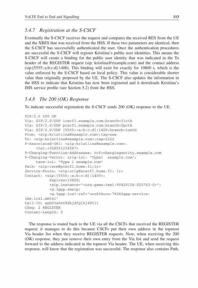
VoLTE End to End and Signalling 113
5.4.7 Registration at the S-CSCF
Eventually the S-CSCF receives the request and compares the received RES from the UEand the XRES that was received from the HSS. If these two parameters are identical, thenthe S-CSCF has successfully authenticated the user. Once the authentication proceduresare successful the S-CSCF will register Kristiina’s public user identities. This means theS-CSCF will create a binding for the public user identity that was indicated in the Toheader of the REGISTER request (sip: [email protected]) and the contact address(sip:[5555::a:b:c:d]:1400). This binding will exist for exactly for 10800 s, which is thevalue enforced by the S-CSCF based on local policy. This value is considerable shortervalue than originally proposed by the UE. The S-CSCF also updates the information inthe HSS to indicate that Kristiina has now been registered and it downloads Kristiina’sIMS service profile (see Section 5.2) from the HSS.
5.4.8 The 200 (OK) Response
To indicate successful registration the S-CSCF sends 200 (OK) response to the UE.
SIP/2.0 200 OKVia: SIP/2.0/UDP icscf1.example.com;branch=3ictbVia: SIP/2.0/UDP pcscf1.example.com;branch=2pctbVia: SIP/2.0/UDP [5555::a:b:c:d]:1400;branch=1uetbFrom: <sip:[email protected]>;tag=newTo: <sip:[email protected]>;tag=2222P-Associated-URI: <sip:[email protected]>,
<tel:+358501234567>P-Charging-Function-Addresses: ccf=chargingentity.example.comP-Charging-Vector: orig-ioi: "Type1 example.com";
term-ioi: "Type 1 example.com"Path: <sip:[email protected];lr>Service-Route: <sip:[email protected]; lr>Contact: <sip:[5555::a:b:c:d]:1400>;
Expires=10800;+sip.instance="<urn:gsma:imei:90420156-025763-0>";+g.3gpp.smsip;+g.3gpp.icsi-ref="urn%3Aurn-7%3A3gpp-service-
ims.icsi.mmtel"Call-ID: apb03a0s09dkjdfglkj49111CSeq: 2 REGISTERContent-Length: 0
The response is routed back to the UE via all the CSCFs that received the REGISTERrequest; it manages to do this because CSCFs put their own address in the topmostVia header list when they receive REGISTER requests. Now, when receiving the 200(OK) response, they just remove their own entry from the Via list and send the requestforward to the address indicated in the topmost Via header. The UE, when receiving thisresponse, will know that the registration was successful. The response also contains Path,

114 Voice over LTE
Service-Route, P-Associated-URI, P-Charging-Function-Addresses (P-C-F-A) headersand P-C-V headers.The Service-Route header allows to send further requests directlyto the S-CSCF without traversing via the I-CSCF. The P-Associated-URI header carriesinformation which other public user identities got registered at the same time (hereone additional identity, which could be user’s ordinary phone number). The P-C-F-Atransports the address of the charging function (here the address of the offline chargingfunction). This enables both S-CSCF and P-CSCF to send charging information to thesame network function. P-C-V contains the IOI, a globally unique identifier exposingthe sending and receiving networks, here identifying both P-CSCF (orig-ioi as receivedfrom P-CSCF in the REGISTER request) and S-CSCF (term-ioi).
5.4.9 Third-Party Registration to Application Servers
After successful registration the S-CSCF will check the downloaded filter criteria of theuser (see Section 5.4.7 and Figure 5.5). We assume that there is a telephony applicationserver (TAS) that provides its services to Kristiina; this TAS needs to know that Kristiinahas now been registered and is therefore available. To inform the TAS about this, filtercriteria have been set which contain a trigger all the REGISTER requests that originatefrom Kristiina’s public user identity. Due to these filter criteria, the S-CSCF will generatea third-party REGISTER request (Figure 5.5) and send it to the TAS whenever Kristiinaperforms a successful registration.
This REGISTER request is destined to the TAS at TAS.example.com, as indicatedin the request URI. As no Route header is included, the request will be sent directlyto that address. The To header includes the public user identity of Kristiina, as this isthe URI that was registered. The S-CSCF indicates its own address in the From header,as it is registering Kristiina’s public user identity on behalf of Kristiina (i.e. as a third
TASS-CSCF
REGISTER
From: KristiinaTo: KristiinaContact: Kristiina UE
Filter Criteria evaluation
200 (OK)
REGISTER
From: S-CSCFTo: KristiinaContact: S-CSCF
200 (OK)
Figure 5.5 IMS third party register by S-CSCF.

VoLTE End to End and Signalling 115
P-CSCF
SUBSCRIBE
To: Kristiina
From: Kristiina
Event: reg
Route: pcscf, scscf
200 (OK)
S-CSCF
SUBSCRIBE
To: Kristiina
From: Kristiina
Event: reg
Route: scscf200 (OK)
NOTIFYNOTIFY
200 (OK)200 (OK)
From: Kristiina
To: Kristiina
XML body: registration
state information
I-CSCF
SUBSCRIBE
To: Kristiina
From: pcscf
Event: reg
Contact: pcscf
200 (OK)
S-CSCF
SUBSCRIBE
To: Kristiina
From: pcscf
Event: reg
Contact: pcscf200 (OK)
NOTIFY
200 (OK)
From: Kristiina
To: pcscf
XML body: registration
state information
P-CSCF
Figure 5.6 Subscription to registration event package.
party). Furthermore, the S-CSCF indicates its own address within the Contact header.This ensures that the TAS never routes directly to Kristiina’s UE, but will always contactthe S-CSCF first. The S-CSCF may also include the original REGISTER request fromthe UE inside the body of this third party REGISTER request.
The TAS will send back a 200 (OK) response for this REGISTER request to the S-CSCF, but will not start acting as a registrar for Kristiina. It will take the REGISTERrequest as an indication that Kristiina has been successfully registered at the S-CSCF. Ifthe TAS needs more information about Kristiina’s registration state (e.g. all other publicuser identities that have been implicitly registered for Kristiina), it can subscribe to theregistration-state information of Kristiina in the same way as the UE and the P-CSCF do(see Section 5.4.10).
5.4.10 Subscription to Registration Event Package
After the registration and authentication has succeeded, both UE and P-CSCF need tosubscribe to the registration state event package (Figure 5.6). This is needed in order toreceive network initiated re-authentication (see Section 5.4.11) and receive informationregarding network initiated de-registration (see Section 5.4.12). In addition, registrationstate event package carries registration status about all available public user identities(all information related to subscription not limited to this particular UE). This statusinformation reveals, for example if particular public user identity is also registered fromother UE.
5.4.11 Re-Registration and Re-Authentication
The IMS UE registers its contact information for a time of 10800 s, which means thatthe binding of the registered public user identities and the physical IP address is kept foraround three hours in the S-CSCF. It is the UE’s responsibility to keep its registrationactive by periodically refreshing its registration, that is before the registration timer

116 Voice over LTE
P-CSCF
200 (OK)
S-CSCF
200 (OK)
NOTIFY NOTIFY
200 (OK)
200 (OK)
(Kristiina’s registrationstate information –‘‘shortened event’’)
I-CSCF
REGISTER REGISTERREGISTER
401 (Unauthorized)401 (Unauthorized)
REGISTER REGISTER REGISTER
200 (OK)
Figure 5.7 Network initiated re-authentication.
lapses in the S-CSCF. To maintain a registration active the UE sends a new REGISTERrequest to the network. This re-registration is handled in the same way as an initial SIPregistration procedure in the network as described in previous sections. If the UE doesnot refresh its registration, then the S-CSCF will silently remove the registration whenthe registration timer lapses.
User authentication procedures are directly coupled to registration procedures. Thereforethe S-CSCF needs to be able to shorten the registration time, in order to re-authenticatethe UE (Figure 5.7). To achieve this, the S-CSCF reduces the expiry time of the user’sregistration, for example to 300 s. The new expiry time is delivered to the UE utilisingthe UE’s subscription to the registration-state event package. In other words the S-CSCFgenerates a NOTIFY request for the registration-state event package, in which it indicatesthat it shortened the registration time and sends this NOTIFY request to the registeredUE. On receiving this request the UE will immediately update the registration expiry timeinformation. Furthermore, all other subscribers to the user’s registration-state information(e.g. the P-CSCF and the subscribed ASs) will receive a NOTIFY request from the S-CSCF with the updated state information. To maintain active registration the UE will sendout a REGISTER request. From then on, the normal registration procedures will take place,during which the S-CSCF can authenticate the user again (see Sections 5.4.5 and 5.4.7).
5.4.12 De-Registration
All things come to an end at some point, and this is also true for the registration ofa user to the IMS. Kristiina might want to be undisturbed and switches off her mobilephone. When doing so, her phone sends another REGISTER request to the S-CSCF,including all the information we have already seen, but indicating that this time it is forde-registration by setting the expiry time to zero (Figure 5.8). The S-CSCF will then clearall the temporary information it has stored for Kristiina, update the data in the HSS andsend a 200 (OK) response to Kristiina’s UE.

VoLTE End to End and Signalling 117
P-CSCF
200 (OK)
S-CSCF
200 (OK)
I-CSCF
REGISTER
Contact:UE IP addressREGISTER
REGISTER
200 (OK)
NOTIFY NOTIFY
200 (OK) 200 (OK)
NOTIFY
200 (OK)
(Kristiina’s registrationstate information –“unregistered event”)
(Kristiina’sregistrationstate information –“unregistered event”)
Figure 5.8 UE initiated de-registration.
P-CSCF S-CSCF
NOTIFY NOTIFY
200 (OK)200 (OK)
(Kristiina’s registrationstate information –“deactivated event”)
NOTIFY
(Kristiina’s registrationstate information – “deactivated event”)
200 (OK)
Figure 5.9 Network initiated de-registration.
Sometimes the network needs to de-register the user (Figure 5.9), for example when UEis reported stolen, unpaid bills, S-CSCF needs to be shut down for administrative reasons.In these cases the S-CSCF would simply send a NOTIFY message with registration-stateinformation to Kristiina’s UE, this time indicating that she has been de-registered.
5.4.13 Related Standards
Specifications relevant to Section 5.4 are:
• 3GPP TS 23.003 – Numbering, addressing and identification.• 3GPP TS 23.228 – IP multimedia subsystem (IMS).• 3GPP TS 24.229 – IP Multimedia call control protocol based on SIP and SDP.• 3GPP TS 29.228 – IMS Cx and Dx interfaces – signalling flows and messages.• 3GPP TS 29.229 – IMS Cx and Dx interfaces based on the diameter protocol.

118 Voice over LTE
• 3GPP TS 33.102 – Security architecture.• 3GPP TS 33.203 – Access security for IP-based services.• RFC2401 – Security architecture for the Internet protocol.• RFC2617 – HTTP Authentication: basic and digest access authentication.• RFC3261 – SIP: session initiation protocol.• RFC3265 – Session initiation protocol (SIP)-specific event notification.• RFC3310 – Hypertext transfer protocol (HTTP) digest authentication using authentica-
tion and key agreement (AKA).• RFC3325 – Private extensions to the session initiation protocol (SIP) for asserted iden-
tity within trusted networks.• RFC3327 – Session initiation protocol (SIP) extension header field for registering non-
adjacent contacts.• RFC3329 – Security mechanism agreement for the session initiation protocol (SIP).• RFC3455 – Private header (P-header) extensions to the session initiation protocol (SIP)
for the 3rd generation partnership project (3GPP).• RRC3608 – Session initiation protocol (SIP) extension header field for service route
discovery during registration.• RFC3680 – A session initiation protocol (SIP) event package for registrations.• RFC4566 – SDP: session description protocol.• RFC5279 – A uniform resource name (URN) namespace for the 3rd generation part-
nership project (3GPP).• http://www.3gpp.org/tb/Other/URN/URN.htm – URN values maintained by 3GPP.• RFC6050 – A session initiation protocol (SIP) extension for the identification of
services.
5.5 IMS VoIP Session
This section shows how our example users Kristiina and Jennifer establish a voice session(see Figure 5.10) and what happens during this procedure. The SIP messages betweenUE and P-CSCF are traversing as described in Section 4.3.2 and depicted in Figure 4.13.
The first step in the session established is to create a session offer based on the user’sdesire and UE capabilities. Section 5.5.1 shows a global system for mobile communicationassociation (GSMA) (IR.92) compliant voice session offer. After the creation of an initialrequest we need to find a way to the desired recipient. This we call here as routingand this is in fact one of the most complex issues within IMS. This and how responseand subsequent request are routed are covered in Section 5.5.2. During the session setupphase the two UEs agree on the set of media they want to use for the session and thecodecs which will be used for the different media types. This procedure is covered inSection 5.5.3. In addition, we need to secure that the required user plane resources to carryactual voice packets are in place on both sides before Jennifer’s UE is allowed to alerther device regarding the incoming voice session (see Section 5.5.4). In this example wedo not show the detailed interaction with the ASs (see Section 4.5.5 how originatingand terminating sessions are routed to AS). For supplementary service execution seeSection 4.6, and for SR-VCC procedures see Section 5.6.2. This section is concludedwith subsections which describe how the charging of a voice session (Section 5.5.5) isdone and how an established session is released (Section 5.5.6).

VoLTE End to End and Signalling 119
I-C
SC
FS
-CS
CF
P-C
SC
FS
-CS
CF
P-C
SC
FA
SA
S
HS
SIN
VIT
EIN
VIT
EIN
VIT
E
INV
ITE
LIR LIA
INV
ITE
INV
ITE
INV
ITE
INV
ITE
100
Try
ing
100
Try
ing
100
Try
ing
100
Try
ing
100
Try
ing
183
183
183
183
183
183
183
183
PR
AC
KP
RA
CK
PR
AC
K
PR
AC
KP
RA
CK
PR
AC
KP
RA
CK
200
(OK
)20
0 (O
K)
200
(OK
)20
0 (O
K)
200
(OK
)20
0 (O
K)
200
(OK
)D
edic
ated
bea
rer
(QC
I1)
esta
blis
hed
Ded
icat
ed b
eare
r(Q
CI1
) es
tabl
ishe
d
UP
DA
TE
UP
DA
TE
UP
DA
TE
UP
DA
TE
UP
DA
TE
UP
DA
TE 20
0 (O
K)
200
(OK
)20
0 (O
K)
200
(OK
)20
0 (O
K)
200
(OK
)20
0 (O
K)
UP
DA
TE
Rin
ging
Use
ran
swer
s
180
(Rin
ging
)18
0 (R
ingi
ng)
180
(Rin
ging
)18
0 (R
ingi
ng)
180
(Rin
ging
)18
0 (R
ingi
ng)
180
(Rin
ging
)18
0 (R
ingi
ng)
200
(OK
)20
0 (O
K)
200
(OK
)20
0 (O
K)
200
(OK
)20
0 (O
K)
200
(OK
)20
0 (O
K)
AC
KA
CK
AC
K
AC
KA
CK
AC
KA
CK
Kris
tiina
’s h
ome
netw
ork
Jenn
ifer’s
hom
e ne
twor
k
Fig
ure
5.10
IMS
sess
ion
initi
atio
n.

120 Voice over LTE
5.5.1 Constructing the INVITE Request
For establishing a voice communication via the IMS, UEs uses the SIP and session descrip-tion protocol (SDP) to setup the session and to agree communication media componentssuch as audio.
INVITE sip: [email protected] SIP/2.0Via: SIP/2.0/UDP [5555::a:b:c:d]:1400; branch=abc123Max-Forwards:70Route: <sip:[5555::55:66:77:88]:7531;lr>,< sip:[email protected];lr>P-Access-Network-Info:3GPP-E-UTRAN-TDD;utran-cell-id-3gpp=244005F3F5F7P-Preferred-Service: urn:urn-7:3gpp-service.ims.icsi.mmtelPrivacy: noneFrom: <sip:[email protected]>;tag=171828To: <sip:[email protected]>Call-ID: cb03a0s09a2sdfglkj490333Cseq: 127 INVITERequire: sec-agreeProxy-Require: sec-agreeSupported: precondition, 100rel, 199Security-Verify: ipsec-3gpp; alg=hmac-sha-1-96; spi-c=98765432;spi-s=87654321; port-c=8642; port-s=7531Contact: <sip:[5555::a:b:c:d]:1400;+g.3gpp.icsi-ref="urn%3Aurn-7%3gpp-service.ims.icsi.mmtel"Accept-Contact: *;+g.3gpp.icsi-ref="urn%3Aurn-7%3gpp-service.ims.icsi.mmtel"Allow: INVITE, ACK, CANCEL, BYE, PRACK, UPDATE, REFER, MESSAGE, OPTIONSAccept:application/sdp, application/3gpp-ims+xmlContent-Type: application/sdpContent-Length: (...)
v=0o=- 2890844526 2890842807 IN IP6 5555::a:b:c:ds=-c=IN IP6 5555::a:b:c:dt=0 0m=audio 49152 RTP/AVP 97 98a=rtpmap:97 AMR/8000/1a=fmtp:97 mode-change-capability=2; max-red=220b=AS:30b=RS:0b=RR:0a=rtpmap:98 telephone-event/8000/1a=fmtp:98 0-15a=ptime:20a=maxptime:240a=inactivea=curr:qos local nonea=curr:qos remote nonea=des:qos mandatory local sendrecva=des:qos none remote sendrecv
SIP
SDP
Let us have a closer look at this.

VoLTE End to End and Signalling 121
5.5.1.1 SIP Information
• The first line tells us the final destination of the INVITE request – which is the SIPURI of Jennifer. The purpose of the Via, Route and Contact headers is covered inSection 5.5.2.
• The Max-Forwards header contains an integer that is decremented by one at each hopto detect a loop (initially it is set to 70).
• The P-Access-Network-Info header is a 3GPP-specific header and indicates the IMSnetwork over which access technology (LTE) the UE is attached to IMS. It also includesthe CGI, which indicates the location of the user.
• P-Preferred-Service header is a 3GPP-specific header and indicates the IMS communi-cation service (here MMTel) that is related to the request.
• The Privacy header is used to signal whether the user wants to hide or make her identityavailable for other users (see Sections 4.6.3.1–4.6.3.4).
• From and To header values do not play a role on IMS routing as in the IMS end-usertrusted identifiers are signalled with P-Asserted-Identity header (not visible here as thisheader is provided by the network not the UE), see for example Section 4.6.3.1.
• Every SIP dialogue is identified by the value of the Call-Id header and by tags in theTo and the From headers of the SIP requests (no tag present in To header it is set byJennifer’s UE).
• The CSeq header field serves as a way to identify and order transactions (here with avalue of 127). Every subsequent request sent from the same end (here Kristiina’s UE)will have a higher CSeq than the preceding request (e.g. PRACK request includes 128,UPDATE 129 and so forth).
• The Require, Proxy-Require and Security-Verify headers are needed to ensure thatIPSec is applied as agreed during IMS registration.
• The Supported header lists the SIP extensions which the Kristiina’s UE is able to use.Here three important extensions (precondition, 100rel, 199) are supported as mandato-rily required in 3GPP and GSMA (IR.92) specifications. ‘100rel’ extension means thatKristiina’s UE will explicitly acknowledge when it receives 100-class response (e.g.183 Session Progress) from Jennifer’s UE. Without this extension, Jennifer’s UE thatsends 183 Session Progress containing the final codec does not get any indication backwhether this response was ever received by the Kristiina’s UE. The ‘199’ extensionmeans that Kristiina’s UE supports SIP response code, 199 ‘Early Dialog Terminated’,which is used to signal that an early SIP dialogue has been terminated before a finalresponse is sent towards the Kristiina’s UE. Preconditions extension is further coveredin Section 5.5.4.
• The Accept-Contact header expresses a preference of the caller (Kristiina) to reach aUE of the called party (Jennifer), which support the indicated capabilities [here IMSmultimedia telephony communication service (MMTel), see also Section 4.6 for moredetailed description of MMTel service]. The called UE also adds all its own supportedcapabilities within the Contact header.
• Finally the SIP contains the Allow header, which lists the set of methods supportedby the user agent (UA) generating the message. The Accept header lists thatKristiina’s UE supports SDP and IMS special extensible markup language (XML)payload, and the Content-Length header indicates the size of the message-body(here SDP).

122 Voice over LTE
5.5.1.2 SDP Information
• The v-line indicates the protocol version and is always set to 0.• The o-line holds parameters related to the owner of the session, who is in this case
Kristiina.• The s-line may include a subject for the session; here empty.• The c-line contains information about the connection that has to be established for the
multimedia session: that is this indicates the addresses used for the real media streams.• The t-line, which indicates when the session was created and how long it is intended
to last. There need be no time limitation to the session set in SDP, as SIP users alreadyend a session by manually sending a BYE request. So, the parameters of the t-line cansafely be given as 0.
• The rest of the SDP parameters are described in Sections 5.5.3 and 5.5.4.
5.5.2 Routing
Kristiina’s UE is unaware at the time of sending the INVITE request how Jennifer’s UEcan be reached. All it can provide is:
• The final destination of the INVITE request – this is the SIP URI of Jennifer (oneof her public user identities, [email protected]) that Kristiina had to indicate (e.g. byselecting it from her phone book).
• The address of the P-CSCF (sip:[5555::55:66:77:88]:7531) – this is the outbound proxyof Kristiina’s UE and will be the first hop to route to. This address is obtained beforeSIP registration during the P-CSCF discovery procedures (see Section 5.3 and step 11).
• The address of the S-CSCF (sip:[email protected]) – this was discovered duringregistration procedures by means of the Service-Route header (see Section 5.4.8).
Armed with this partial route information the INVITE request is sent on its way. Itfirst traverses the P-CSCF and then the S-CSCF that have been selected for Kristiina. TheS-CSCF executes services as described in Section 4.5.5 and after that the S-CSCF hasno further routing information available for the request other than the final destination(i.e. the public user identity of Jennifer, sip: [email protected]). As Kristiina’s S-CSCFdoes not act as a registrar for Jennifer, it can only resolve the host part of the address:csp.com. This domain name is sent to the DNS server and the S-CSCF will receive backone or more I-CSCF addresses of Jennifer’s home network, will select one of them andwill send the INVITE request to it.
The I-CSCF just acts as the entry point to Jennifer’s home network. Figure 5.10 showsthat the I-CSCF asks the local HSS for the address of the S-CSCF that was selectedfor Jennifer with a Location Information Request (LIR). The HSS returns the address ofS-CSCF in a Location Information Answer (LIA). The I-CSCF sends the INVITE furtheron to the S-CSCF. Jennifer’s S-CSCF executes services (see Section 4.5.5) and after thatit acts as the registrar and replaces Jennifer’s SIP URI in the Request URI of the INVITErequest with the contact address that she has registered. It does not send the request directlyto Jennifer’s UE, because it remembers the Path header information from registration.The INVITE request, therefore, is first sent to Jennifer’s P-CSCF. The S-CSCF knows

VoLTE End to End and Signalling 123
the address of the P-CSCF, as that was received within the Path header during Jennifer’sregistration (see Section 5.4.3). The P-CSCF finally forwards the INVITE request toJennifer’s UE over the IPsec SA. This shows that for the initial request the route fromKristiina to Jennifer is put together piece by piece, as the originating UE and the CSCFshave only information about the next one or two hops that have to be traversed. In orderto make further routing within the dialogue easier, SIP routing mechanisms will be used:
• All CSCFs put their addresses on top of the Via header – this allows all responses tothe INVITE request to be sent back over exactly the same route as the request.3
• All CSCFs, other than Jennifer’s I-CSCF, put their addresses on top of the Record-Route header – this allows all subsequent requests in the dialogue to be sent over theCSCFs that put themselves in the Record-Route header. The I-CSCF in Jennifer’s homenetwork fulfilled its routing task when it discovered the addresses of Jennifer’s S-CSCF;so, it is no longer needed on the route.
Jennifer’s UE now creates a response to the received INVITE request which is, dueto the usage of preconditions (see Section 5.5.4), a 183 (Session Progress) response. TheUE puts its own IP address in the Contact header to indicate the address it wants touse to receive subsequent requests in this dialogue. The contact address also includesthe protected server port of Jennifer’s UE (1006), which guarantees that all subsequentrequests will be received via the established IPsec SA as well. The Record-Route andVia headers of the INVITE request also go into the response. After doing so, Jennifer’sUE sends the response to the address and port number of the topmost entry in the Viaheader, which is the protected server port of the P-CSCF. The P-CSCF identifies that thisis a response to the INVITE and it removes its own address from the Via header andsends the response to the topmost entry in the Via header. Similarly other CSCFs and ASsremoves their own Via entry and send the message towards the next entry in the Via.4
After receiving the response, Kristiina’s UE:
• Stores the IP address of Theresa’s UE, as received in the Contact header;• Stores the Record-Route list after reversing the order of all entries in it.
Figures 5.11 and 5.12 show our example in action (for simplicity HSS and ASs are notshown).
When one of the two UEs needs to send a subsequent request within a dialogue, itcopies the stored Record-Route entries into the Route header of the new requests andthe remote UE’s IP address into the Request URI. The request then is routed towardsthe remote UE by strictly following the entries in the Route header (Figure 5.12). EveryCSCF that is traversed puts itself in the Via header, in order to get all the responses tothis request. As the I-CSCF did not record any route in the beginning, it does not receive
3 Likewise TASs (see Section 4.6.3) and Service Centralisation and Continuity AS (see Section 5.6.2) will includetheir addresses on the Via header and Record-Route (not shown here for simplicity).4 CSCFs may re-write their Record-Route entries to distinguish requests received from different directions. P-CSCFsare expected to re-write Record-Route due to use of IPSec (IPSec secured port number is only present betweenUE and P-CSCF). This type of detail is not shown in Figures 5.11 and 5.12.

124 Voice over LTE
RE
GIS
TE
RC
on
tact
:55
55::
a:b
:c:d
RE
GIS
TE
RC
onta
ct:
5555
::a:b
:c:d
Pat
h:
pcs
cfa
RE
GIS
TE
RC
onta
ct:
5555
::a:b
:c:d
Pat
h: p
cscf
a
200
Ser
vice
-Rou
te:
scsc
faP
ath:
pcsc
fa
200
Ser
vice
-Ro
ute
:sc
scfa
Pat
h:p
cscf
a
200
Ser
vice
-Rou
te:
scsc
faP
ath:
pcsc
fa
RE
GIS
TE
RC
onta
ct:
5555
::1:2
:3:4
Pat
h: p
cscf
b
RE
GIS
TE
RC
onta
ct:
5555
::1:2
:3:4
Pat
h:
pcs
cfb
RE
GIS
TE
RC
on
tact
:55
55::
1:2
:3:4
200
Ser
vice
-Rou
te:
scsc
fbP
ath:
pcsc
fb
200
Ser
vice
-Rou
te:
scsc
fbP
ath:
pcsc
fb
200
Ser
vice
-Ro
ute
:sc
scfb
Pat
h:p
cscf
b
INV
ITE
R-U
RI:
UE
-BV
ia:
UE
-A
Ro
ute
: p
cscf
a,sc
scfa
Co
nta
ct:
5555
::a:
b:c
:d
INV
ITE
R-U
RI:
UE
-BV
ia:
pcs
cfa,
UE
-A
Ro
ute
:sc
scfa
Rec
-R:
pcs
cfa
Con
tact
:55
55::a
:b:c
:d
INV
ITE
R-U
RI:
UE
-BV
ia:
scsc
fa,
pcsc
fa,
UE
-A
Rec
-R:
scsc
fa,
pcsc
fa
Con
tact
:55
55::a
:b:c
:d
INV
ITE
R-U
RI:
UE
-BV
ia:
icsc
fb1
scsc
fa,
pcsc
fa,
UE
-A
Ro
ute
: sc
scfb
Rec
-R: s
cscf
a,pc
scfa
Con
tact
:55
55::a
:b:c
:d
INV
ITE
R-U
RI:
555
5::1
:2:3
:4V
ia:
scsc
fb,
icsc
fb1,
scsc
fa,
pcsc
fa,
UE
-A
Ro
ute
: p
cscf
b
Rec
-R:
scsc
fb,
scsc
fa,
pcsc
fa
Con
tact
:55
55::a
:b:c
:d
INV
ITE
R-U
RI:
555
5::1
:2:3
:4V
ia:
pcs
cfb
,sc
scfb
,ic
scfb
1,sc
scfa
,pc
scfa
,U
E-A
Rec
-R:
pcs
cfb
,sc
scfb
,sc
scfa
,pc
scfa
Con
tact
:55
55::a
:b:c
:d
P-C
SC
FP
-CS
CF
I-C
SC
FI-
CS
CF
S-C
SC
FS
-CS
CF
I-C
SC
F
Kris
tiina
’s h
ome
netw
ork
Jenn
ifer’s
hom
e ne
twor
k
Fig
ure
5.11
Rou
ting
anin
itial
INV
ITE
requ
est.

VoLTE End to End and Signalling 125
Fig
ure
5.12
Rou
ting
are
spon
seto
the
initi
alIN
VIT
Ere
ques
tan
dsu
bseq
uent
requ
est.

126 Voice over LTE
any subsequent request. For example, Tobias’s UE has to send back a PRACK request toacknowledge the received 183 (Session Progress) response. (see Section 5.2).
A subsequent request within a dialogue does not include a Contact header, as theaddresses of the two UEs were already exchanged during the sending and receiving ofthe initial request and its first response. Furthermore, the CSCFs will not put any Record-Route headers in the request, because the route was already recorded during the initialrequest. Theresa’s UE will send back a 200 (OK) response to this PRACK request. Thisresponse will be routed back on the basic of the Via header entries. Record-Route headersare no longer returned.
Figures 5.13 and 5.14 summarise the IMS routing principles.
Figure 5.13 Routing principles of initial request and response to it.
UE A UE Be.g. PRACK
200 OKS-CSCF-AP-CSCF-A S-CSCF-B P-CSCF-B
(5) Remove own entry from Route(6) Route to Request URI =UE B’s Contact
(10) Remove own Via entry / send to next
(7) Create response(8) Copy Via into response(9) Send response to topmost Via
(1) Send PRACK to Contact of UE B (received in response to INVITE request)
(2) Put stored (reversed) Record-Route entries to Route header
(3) Remove own entry from Route(4) Route to next hop in Route header
(11) Remove own Via entry / send to next
Figure 5.14 Routing principles of subsequent requests and their responses.
VoLTE End to End and Signalling 127
5.5.3 Media Negotiation
Section 5.5.1 contained a full-blown example of INVITE request. Here we will takecloser look at SDP of it and how it is used agreed media types and the codecs for aspecific session.
Here we have modified our earlier INVITE example such way that we have added asecond audio codec and video media to the initial SDP in order to demonstrate IMS medianegotiation capability. In addition, parameters which are not relevant for the media andcodec negotiation procedure point of view are ignored.
m=audio 49152 RTP/AVP 97 98 99a=rtpmap:97 AMR/8000/1a=rtpmap:98 G.726-32/8000a=rtpmap:99 telephone-event/8000/1m=video 3400 RTP/AVP 98a=rtpmap:98 H264/90000
Individual media lines, or m-lines, represent the two different media streams that theuser wants to send:
m=audio 49152 RTP/AVP 97 98 99m=video 3400 RTP/AVP 98
The first line indicates that Kristiina intends to use audio for this session and thather UE will use the local port 49152. Real-time transport protocol (RTP)/audio videoprofile (AVP) will be used as the transport protocol for audio-related media. Differentdynamic payload types are indicated with the numbers 97–99. These three numbersare further mapped in adaptive multi-rate (AMR) (a=rtpmap:97), G.726 (a=rtpmap:98)speech codecs and telephone event5 representation of dual-tone multi-frequency (DTMF)tones (a=rtpmap:99). Similarly, the second m-line indicates that Kristiina intends to usevideo for this session and that her UE will use the local port 3400 and payload type ismapped to H.264 codec.
This SDP offer is sent within the body of the INVITE request to Jennifer as describedin Section 5.5.2. The SDP offer arrives at Jennifer’s UE due to SIP routing of the INVITErequest (as shown in Figure 5.10).
Jennifer’s UE generates an SDP answer for the received offer, which looks like this:
m=audio 49540 RTP/AVP 98 99a=rtpmap:98 AMR/8000/1a=rtpmap:99 telephone-event/8000/1m=video 0 RTP/AVP 98
From the audio m-line we see that only two payload types are left. In IMS the ter-minating UE, here Jennifer’s UE, is responsible to select a single codec per media and
5 The telephone event defines a text-based representation of these DTMF tones and other telephone-related tonesthat can be transported over RTP.

128 Voice over LTE
Fig
ure
5.15
IMS
med
iare
sour
cere
serv
atio
nan
dpo
licy
cont
rol.

VoLTE End to End and Signalling 129
here the AMR-NB speech codec was selected and another codec was simply dropped.6
In addition Jennifer’s UE was not able to support video therefore the port number in thesecond m-line is set to zero and related a-lines are simply dropped. The SDP answer mustrepeat all the m-lines that are included in the SDP offer. Therefore, the UE cannot dropthe second m-line from here: the only way to indicate that this video cannot be handled isto set the port number to 0. This SDP answer is contained in the 183 (Session Progress)response, as shown in Figure 5.15.
5.5.4 Media Resource Reservation and Policy Control
Section 5.5.1 contained a full-blown example of the INVITE request. Here we will takecloser look at the SDP of it and how it is used to signal status of resources for sessionmedia traffic. In our example both UEs are LTE connected and make use of dedicated bear-ers for voice packets (see Section 4.3.3). These dedicated bearers need to be establishedduring the IMS session setup. The establishment of dedicated bearers may consume sometime and may even fail: when, say, insufficient resources are available over the wirelesslink. This means that, until the bearers have been established, it cannot be guaranteed thatthe agreed media connection can be established at all. Therefore, Jennifer’s UE shouldnot inform her about the incoming session request (INVITE): that is it should not start toring until it has confirmation that the required resources have been successfully reservedlocally as well as at the calling user’s end. In order to achieve this, both UEs utilise SDPprecondition mechanism introduced in (RFC3312) that allows a UE to delay completionof a SIP session establishment until one or both ends have successfully completed theirresource reservation. This extension to SIP and SDP is mandatorily supported by everyUE that connects to IMS. Figure 5.15 provides an overview of media resource reservationand policy control.
Section 5.5.1 contained a full-blown example of INVITE request. In order to illustratethe media resource mechanism, we take just focus on SDP parameters which are requiredto setup an appropriate dedicated bearer and to ensure that Jennifer is not alerted priorIMS media resources are in place.
m=audio 49152 RTP/AVP 97 98a=rtpmap:97 AMR/8000/1a=rtpmap:98 telephone-event/8000/1b=AS:30b=RS:0b=RR:0a=inactivea=curr:qos local nonea=curr:qos remote nonea=des:qos mandatory local sendrecva=des:qos none remote sendrecv
6 If the terminating UE does not select single codec per media then the originating IMS UE needs to take finalcodec decision and signal the selected codec in the next request, PRACK.

130 Voice over LTE
First, we look at the penultimate line:
a=des:qos mandatory local sendrecv
This indicates the desired (des) QoS precondition at the calling user (local) end. Theresources for the calling user need to be reserved in both the sending and receivingdirections (sendrecv), as the audio stream is bidirectional (i.e. both users can talk to eachother and hear what the other says). It also states that the session will not take place ifthe indicated resources cannot be reserved by the calling user (mandatory). The last line:
a=des:qos none remote sendrecv
indicates the desired (des) QoS-related preconditions at the called user (remote) end. Asthe calling and the called UE are not directly connected to each other, the calling UE isunaware of how the remote UE is attached to the network. It might be that Jennifer’s UEdoes not need to perform any resource reservation, as it is connected via a CS telephonynetwork. Therefore, the calling end can only indicate that, if the remote end needs toreserve resources, then they should be reserved in both the sending and receiving directions(sendrecv); however, the calling end is currently unaware that this is really required inorder to get a media session established (none).
Up to now, the calling UE has only expressed the desired (des) preconditions for eachend, but it also needs to talk about the current status of resource reservation. This is thesubject of the following two new lines:
a=curr:qos local nonea=curr:qos remote none
These two lines indicate that currently (curr) no (none) QoS-related preconditions havebeen fulfilled by either the calling end (local) or the called end (remote). The a=des linesmake it possible to set preconditions for the local and the remote user, while the a=currlines indicate the extent to which the set preconditions are already being fulfilled.
In addition to precondition related parameters the SDP contains information about thedesired media in the first three lines, as explained in Section 5.5.3. The next three lines:
b=AS:30b=RS:0b=RR:0
reveal that UE has calculated that required bandwidth for RTP traffic is 30 kbit/s and itexpresses that it is not going to use RTP control protocol (RTCP; b:RS and b:RR valuesset to zero) while engaged on this call.7
7 GSMA (IR.92) states that UEs engaged on active call are mandated to disable RTCP as the policy controlfunctionality takes care of supervising user plane link aliveness. Using RTCP for voice media would not bringadditional benefit but it would consume upto 5% more bandwidth. Use of RTCP is required when a session is puton hold.

VoLTE End to End and Signalling 131
The seventh lines tells us that Kristiina’s UE wants to make sure that the other enddoes not send user plane traffic prior the resources are ready. Later on when the networkhas established a dedicated bearer then Kristiina’s UE will send media status to allowtraffic in both directions.
a=inactive
Here we have assumed that Jennifer’s UE is also attached to LTE and supports thepreconditions mechanism. Therefore, it will respond to the received SDP offer with awell-formed answer and will include its own preconditions. Once again, we only showhere those preconditions and key media-related information:
m=audio 49540 RTP/AVP 98 99a=rtpmap:98 AMR/8000/1a=rtpmap:99 telephone-event/8000/1b=AS:30b=RS:0b=RR:0a=inactivea=curr:qos local nonea=curr:qos remote nonea=des:qos mandatory local sendrecva=des:qos mandatory remote sendrecva=conf:qos remote sendrecv
The important thing to note here is that the remote and local ends have changed,because from Jennifer’s point of view her UE is local and Kristiina’s is remote. Her UEnow indicates its own preconditions line by line. Line 8:
a=curr:qos local none
states it has currently not reserved any local qos-related resources. Line 9:
a=curr:qos remote none
states it received information from the remote end (in the first offer) that no qos-relatedresources have been reserved at the moment. Line 10:
a=des:qos mandatory local sendrecv
states it mandatorily requires that its own resources get reserved in both the sending andreceiving directions, before the audio session can start. Note that the initial value ‘none’,as set from the calling end, has changed to ‘mandatory’ because Jennifer’s UE is alsoLTE attached and, therefore, is also mandated to reserve the resources locally before itcan start sending media. Line 11:
a=des:qos mandatory remote sendrecv

132 Voice over LTE
Table 5.4 Policy rule example
SDP information Policy rule information
Media type (audio) QCI (1)Speech codec (AMR) Guaranteed bit rate/maximum bit rate
(30 kbit/s)IP addresses (Kristiina and Jennifer as
communicated in c-lines of SDP)Packet filter (5555::a:b:c:d and
5555::1:2:3:4)Port numbers (Kristiina and Jennifer, as negotiated
in Section 5.5.3Packet filter (49152 and 49540)
a=inactive (flow status) IP flow status (disabled, all media blocked)
states it received information from the remote end (in the first offer) that resources aremandatorily reserved in both the sending and receiving directions. Line 12:
a=conf:qos remote sendrecv
states the calling UE (remote) should send a confirmation (conf) at the moment theresources (qos) have been reserved in the sending and receiving directions (sendrecv).This is a new line that the called end adds to SDP. It is a necessary addition because thecalled UE is not intended to ring the called user or to start sending media until both endshave reserved the resources. This SDP answer is now sent in the 183 (Session Progress)response to the calling UE.
Once the P-CSCF receives the 183 response it passes the response towards Kristiina’sUE but in addition it sends the diameter AA request (AAR) command to PCRF. ThisAAR command conveys session information (such as IP addresses, port numbers, mediatype (audio), negotiated codec(s) (AMR), bandwidth data, flow status (disabled as thesession is not yet accepted) obtained from SDP offer/answer. When the PCRF receivesthis it performs QoS authorisation and finds the associated Gx session towards the S/P-GW using the served user’s UE IP address. If the QoS authorisation is successful thePCRF creates policy rules based on information received in AAR (see Table 5.4) andsends the Rx AA answer (AAA; with a success value to indicate successful authorisation)towards P-CSCF.
The created policy rule is then delivered to P-GW using another diameter command,re-auth-request (RAR). This rule comprises information which is used by the P-GWto enforce QoS and to apply media flow and traffic treatment for voice. The policyand charging enforcement functionality (PCEF) inside the P-GW applies the receivedinformation which causes an establishment of a dedicated bearer for voice traffic, asshown in Figure 5.16.
1. The PCRF sends the RAR command towards the PCEF in the P-GW. This RAR con-tains media flow and QoS information, that is the flow information, QCI, maximumrequested bandwidth UL/DL (MBR), GBR UL/DL, ARP for the media flows of theIMS voice session. Table 5.5 gives an example of the flow of QoS information, whichcomes from PCRF over the Gx reference point and is used by PCEF for dedicatedbearer establishment.

VoLTE End to End and Signalling 133
S/P-GWeNodeB MME PCRF
1. Re-Auth-Request (QCI, MBR, GBR, Flow Information)
2. Create Bearer Request (QCI, MBR, GBR, ARP, TFT)
9. Create Bearer Response
5. RRC Connection Reconfiguration Complete
4. RRC Connection Reconfiguration (QoS, Session Management Request, Radio Bearer ID)
6. Bearer Setup Response
7. Direct Transfer (Session Management Response)
8. Session Management Response
10. Re-Auth-Answer
PCRF gets service information from a P-CSCF
3. Bearer Setup Request/Session Management Request (QCI, MBR, GBR, ARP, TFT, Bearer ID)
Figure 5.16 Dedicated EPS bearer establishment for voice media.
Table 5.5 QoS information over the Gxreference point
Protocol IPSource IP address 5555::1:2:3:4Source port 49540Destination port 49152Destination IP address 5555::a:b:c:dQCI 1MBR (UL/DL) 30 kbit/sGBR (UL/DL) 30 kbit/s
When the P-GW gets this information it recognises that there is no bearer availablefor the provided QCI and ARP pair. The P-GW initiates a new dedicated bearercreation. P-GW uses this flow and QoS information to establish the dedicated EPSBearer. P-GW assigns bearer level values of QCI, ARP, GBR/MBR. In the exampleabove the PCRF did not send ARP, so P-GW uses the default bearer ARP. The P-GWgenerates also a traffic flow templates (TFTs) based on the flow information. TFT ismandatory for the dedicated bearer and it is used by UE and P-GW to map traffic toright bearer.
2. The S/P-GW sends create bearer request messages to MME for establishing dedicatedbearer which includes IMSI, EPS Bearer QoS, TFT and so on. For voice media thededicated EPS bearer QoS has QCI = 1, MBR/GBR = 30 kbit/s and ARP = 9. TFT

134 Voice over LTE
contains uplink packet filters for UE, for example IP address = 5555::1:2:3:4 andport number = 49540.
3. The MME allocates EPS bearer identity for the dedicated bearer and sends it togetherwith EPS bearer QoS and TFT information to the UE in the session managementrequest inside the bearer setup request message to the eNodeB.
4. The eNodeB maps the EPS bearer QoS to the radio bearer QoS and then sends aRRC connection reconfiguration message to the UE. This contains also a sessionmanagement request sent by MME.
5. The UE stores the new bearer QoS settings and EPS bearer identity given by thenetwork in the session management request. Signalling contains also informationto which default bearer this dedicated bearer is linked, called the linked EPS beareridentity (LBI). The UE uses uplink TFT to identify voice traffic flow coming from theapplication layer and matches uplink traffic to right radio bearer on the air interface.After configuration the UE returns the RRC connection reconfiguration completemessages to the eNodeB.
6. The eNodeB acknowledges the bearer activation to the MME with a bearer setupresponse message. The eNodeB indicates that requested EPS Bearer QoS can beallocated for voice media and there is 30 kbit/s GBR reserved.
7. The UE sends a session management response, including EPS bearer identity, toMME via eNodeB in a direct transfer message.
8. The eNodeB forwards the session management response message to the MME insidean uplink NAS transport message.
9. After radio setup the MME acknowledges the bearer activation to the S/P-GW bysending a create bearer response message.
10. Because the dedicated bearer was triggered by a PCRF, the P-GW sends a re-auth-answer (RAA) message to inform the PCRF of the successful rule installation.
After receiving the 183 (Session Progress) response Kristiina’s UE acknowledges thereceipt of 183 with a PRACK request. This request does not contain SDP informationas the codec selection has been made and resources are not yet established; there is nochange in SDP preconditions.
As soon as the P-GW initiated dedicated bearer (QCI1) is ready Kristiina’s UE confirmsthis to the Jennifer’s UE by sending a SIP UPDATE request. This UPDATE request willinclude a second SDP offer in its body, which shows that the resources at the calling endhave been reserved:
m=audio 49152 RTP/AVP 97 98a=sendrecva=rtpmap:97 AMR/8000/1a=rtpmap:98 telephone-event/8000/1a=curr:qos local sendrecva=curr:qos remote nonea=des:qos mandatory local sendrecva=des:qos mandatory remote sendrecv
The only differences here are that the first a=curr line has changed from ‘none’ to‘sendrecv’ and the media status has changed from ‘inactive’ to ‘sendrecv’. Consequently,

VoLTE End to End and Signalling 135
Kristiina’s UE indicates that the status of the local QoS-related resources for the audiostream has changed. They have now been successfully reserved in both the sending andreceiving directions. Let us assume that also Jennifer’s UE has now a dedicated bearerestablished and it can immediately start to ring after sending the 200 (OK) response forthe UPDATE request, because it is now sure that both ends have sufficient resourcesreserved to send and receive the audio stream. When it starts to ring, it sends a 180(Ringing) response to the INVITE request in parallel.
The 200 (OK) for the update will include a second SDP answer with the followingSDP information about the audio stream:
m=audio 49540 RTP/AVP 98 99a=sendrecva=rtpmap:98 AMR/8000/1a=rtpmap:99 telephone-event/8000/1a=curr:qos local sendrecva=curr:qos remote sendrecva=des:qos mandatory local sendrecva=des:qos mandatory remote sendrecv
We can see from this that all the current states for resource reservation match thedesired states; so, the preconditions negotiation has been successful and has finished.
5.5.5 Charging
This section explains how the communication services providers of our example usersKristiina and Jennifer perform their charging procedures. Here our assumptions are thatboth communication service providers are providing VoLTE service using the IMS APNand therefore all charging decision are done in the IMS layer and charging on IMSAPN is disabled in EPC. Let us further assume that Kristiina is a postpaid (offline charg-ing) subscriber and Jennifer is a prepaid (online charging) subscriber.
Figure 5.17 shows our example VoLTE session. It highlights key charging related SIPparameters and reveals when IMS functions contact online and offline charging entitieswhich are further described in this section.
5.5.5.1 Offline Charging
Earlier in Section 5.5.2 we have shown that IMS signalling traverses through variousIMS entities.8 In fact, each offline charging-capable entity contains an integrated functioncalled a charging trigger function (CTF). The CTF is aware of charging triggers (suchas the beginning of IMS sessions, IMS session modification, IMS session termination,sending of message, subscribing to an event, publishing presence information) and is ableto decide when it needs to contact the charging data function (CDF), the central point inthe offline charging system. When a trigger condition is met the CTF collects charging
8 Although, our example here shows only CSCFs the reader should keep in mind that all IMS entities are able togenerate offline charging information as explained in Section 3.4.4.5.

136 Voice over LTE
P-CSCF I-CSCFS-CSCFCDF OCS P-CSCFS-CSCF
INVITE INVITEP-C-V: ICID
INVITEP-C-V: ICID,IOI
INVITEP-C-V: ICID,IOI
CCR(Initial)
CCA(Initial)
INVITEP-C-V: ICIDP-C-F-A: ecf
INVITE
183 183183P-C-V: IOI
183P-C-V: IOI
183183
Session initiation continues
200 (OK) 200 (OK)200 (OK)200 (OK)200 (OK)200 (OK)
ACR(Start)
ACA(Start)
Session ongoing
User disconnects
BYE BYEBYEBYEBYE
CCR(Terminate)
CCA(Terminate)
ACR(Stop)
ACA(Stop)
200 (OK) 200 (OK)200 (OK)200 (OK)200 (OK)200 (OK)
Kristiina’s home network Jennifer’s home network
Actions to de-activatededicated bearer
Actions to de-activatededicated bearer
ACR(Start)
ACR(Start)
ACR(Stop)
ACR(Stop)
Figure 5.17 VoLTE charging.
information from the signalling message and sends the offline charging information tothe CDF using diameter accounting requests (ACRs) via the Rf interface. The requestcontains much information about the event that launched the trigger (e.g. type ofrequest INVITE/MESSAGE/SUBSCRIBE, calling party address, called party address,time stamps). The CDF uses a diameter accounting answer (ACA) to acknowledge thereceived request.
The offline charging system needs to support both session- and event-based charging.IMS functions know the request type that need to be indicated to the CDF. This is achievedusing a suitable value in the accounting record type AVP (‘event’ for events and ‘start’,‘interim’, ‘stop’ for sessions) in the ACR. IMS session-related ACRs are called start,interim and stop and are sent at the start, during and at the end of a session, as the nameimplies.9 Nonsession-related ACRs are called event ACRs. Event ACRs cause the CDFto generate corresponding Charging Data Records (CDRs), while session ACRs cause theCDF to open, update and close the corresponding CDRs.
In an IMS session three different phases can be detected (session initiation, sessionmodification, session release). At beginning of a session (200 OK, acknowledging anINVITE, is received), the CTF inside an IMS entity monitors the signalling traffic anddetects a triggering point defined for reception of 200 OK, acknowledging an invite.When the triggering point is met the CDF collects information from the signallingmessages (e.g. calling party address, called party address, time stamps, ‘audio’ SDP mediacomponent), assembles the charging information that matches the detected chargeable
9 As an exception during the session setup phase I-CSCF may send ACR[Event] when it receives anINVITE request.

VoLTE End to End and Signalling 137
event and forwards the charging information towards the CDF via the Rf reference pointusing an ACR (start) request (see Figure 5.17). Usage of an ACR (start) prompts theCDF to open a CDR for this session. When the same session is modified (RE-INVITE orUPDATE is received), for example a video component is added – the CTF could againtrigger this event and collect the necessary information again (e.g. calling party address,called party address, time stamps, ‘audio + video’ SDP media component). This changedcharging information is sent again to the CDF, but this time an ACR (interim) requestis used. Finally, when the session ends (BYE is received) the CTF constructs the ACR(stop) request to indicate session termination (see Figure 5.17). Based on these chargingevents, the CDF can create a single CDR including, for example A-party information,B-party information, total session time, audio session time and video session time.
In the case of a single end user to network transaction (e.g. sending a SIP MESSAGEcontaining SMS) a single ACR/ACA (event) is sufficient.
So far we have described how charging information is delivered from an IMS entityto the CDF. From Figure 3.22 we can see that there are further steps ahead before abilling system can send an actual bill to a user. The next step is to transfer CDRs fromthe CDF on towards the charging gateway function (CGF). The CGF is needed as therecan be multiple CDFs involved in a single session/nonsession event because differentIMS entities may send charging information to different CDFs (e.g. due to roamingor configuration reasons). The CGF validates, consolidates, pre-processes the incomingCDR (e.g. filters unnecessary fields and adds communication service provider-specificinformation), and may correlate different CDRs before passing them to the billing system.Table 5.6 summarises the key procedures supported by different offline charging functions.
5.5.5.2 Online Charging
The purpose of online charging is to perform credit control before usage of IMS ser-vices/resources. Two different models exist: direct debiting and unit reservation. In direct
Table 5.6 Summary of offline charging functions
Offline charging function Key procedures
Charging triggering function (CTF) Monitors SIP signallingDetects trigger conditionExtracts information from SIP signalling and assemblies
charing informationSends charing information to CDF
Charging data function (CDF) Constructs CDRsDelivers CDRs to CGF
Charging gateway function (CGF) Correlates, consolidates, filters unnecessary fields andadds communication service provider-specificinformation to the received account information
CDR error handling and storageDelivers CDRs to billing systemPre-processes CDRs
Billing system Creates the actual bill

138 Voice over LTE
debiting, an IMS network entity contacts the online charging system (OCS) and askspermission to grant the usage of services/resources. The OCS uses an internal ratingfunction to find the appropriate tariff for an event based on the received information, ifthe cost was not given in the request. After resolving the tariff and the price, the OCSchecks whether the user has enough credits in their account. If so, the OCS deducts asuitable amount of money from the user’s account and grants the request from the IMSentity. In the unit reservation model, the OCS receives a credit control request from anIMS entity and uses an internal rating function to determine the price of the desired ser-vice according to the service-specific information provided by the IMS entity, if the costwas not given in the request. Then the OCS reserves a suitable amount of money fromthe user’s account and returns the corresponding number of resources to the requestingIMS entity. Among the number of resources could be, for example, time or allowed datavolume. When resources granted to the user have been consumed or the service has beensuccessfully delivered or terminated, the IMS entity informs the OCS of the number ofresources consumed. Finally, the OCS deducts the used amount from the user’s account.It is also possible for the OCS to receive subsequent requests from the IMS entity duringservice execution if all granted resources are consumed. In this case the OCS needs toperform a new credit authorisation.
The direct debiting model is appropriate when the IMS entity knows that it could deliverthe requested service to the user itself. For example, a game AS could send a credit controlrequest and inform the OCS of the service (say, a game of rally) and the number of items(say, two) to be delivered. Then the OCS uses the rating function to resolve the tariff(0.3 euros) and to calculate the price based on the number of delivered units 0.6 euros).Finally, 0.6 euros are deducted from the user’s account and the OCS informs the gameAS that two units have been granted within the credit control answer. 3GPP’s definitionfor this online charging model is immediate event charging (3GPP TS 32.240).
The unit reservation is suitable when the IMS entity is unable to determine beforehandwhether the service could be delivered or when the required number of resources are notknown prior to the use of a specific service (e.g. duration of multimedia session). The unitreservation model is usually applied to sessions (3GPP’s term for this is session chargingwith unit reservation) but it is also possible to apply nonsession related requests (3GPP’sterm for this is event charging with unit reservation).
The Ro reference point is defined for online charging. It transfers credit control requestsand answers between the OCS and three different IMS entities which are able to performonline charging [AS, multimedia resource function controller (MRFC) and S-CSCF viathe IMS-gateway function (GWF)]. The credit control request and credit control answercommands from (RFC4006) are used for this purpose. In addition, 3GPP has defined 3GPPcredit control AVPs to enhance the internet engineering task force’s (IETF’s) solution(3GPP TS 32.299) to meet the charging requirements of 3GPP.
To enable direct debiting the IMS entity sends a credit control request to the OCS anduses the value ‘EVENT REQUEST’ in a credit control request (CCR)-type AVP andthe value ‘DIRECT DEBITING’ in the requested action AVP. For example, an IP shortmessage gateway (IP-SM-GW) may receive a request from a user to send a messageto somebody. The IP-SM-GW knows that the user is a pre-paid user and, therefore, itneeds to seek permission from the OCS. It constructs a credit control request, sets theCCR-type AVP, requested action AVP and any other required AVP correctly, and thensends the request to the OCS. The OCS gets the request and, if it does not contain
VoLTE End to End and Signalling 139
information about the price of service, the OCS uses a rating function before consultingthe user’s account. When the user has enough credits in the account the OCS grantsthe request with a credit control answer. Finally, the IP-SM-GW allows the service andsends the message towards the destination.
To enable session charging with unit reservation the IMS entity sends a credit controlrequest to the OCS and then uses values ‘INITIAL REQUEST’, ‘UPDATE REQUEST’and ‘TERMINATION REQUEST’ in the CCR-type AVP as follows:
• The ‘INITIAL REQUEST’ value is used when the IMS entity receives the first servicedelivery request.
• The ‘UPDATE REQUEST’ value is used when the IMS entity request reports thenumber of units used and indicates a request for additional units.
• The ‘TERMINATION REQUEST’ value is used when the IMS entity reports that thecontent/service delivery is complete or the final allocated units have been consumed.
To enable event charging with unit reservation the IMS entity sends a credit controlrequest to the OCS and then uses the values ‘initial request’ and ‘termination request’ inthe CCR-type AVP as follows:
• The ‘INITIAL REQUEST’ value is used when the IMS entity receives the first servicedelivery request.
• The ‘TERMINATION REQUEST’ value is used when the IMS entity reports thatcontent/service delivery is complete.
5.5.5.3 VoLTE Charging
When Kristiina’s P-CSCF receives the INVITE request it creates a new ICID (seeFigure 5.17). With ICID it is possible to correlate session/transaction related chargingdata generated in different IMS elements. The ICID is included in the P-Charging-Vector(P-C-V) header.
INVITE sip:[email protected] SIP/2.0P-Charging-Vector: icid-value="AyretyU0dm+6O2IrT5tAFrbHLso
=023551024"
Kristiina’s S-CSCF stores the ICID and adds an originating Inter Operator Identifier(IOI) in the P-C-V header. This IOI value reveals to Jennifer’s communication serviceprovider the originating communication service provider’s identifier:10
INVITE sip:[email protected] SIP/2.0P-Charging-Vector: icid-value="AyretyU0dm+6O2IrT5tAFrbHLso
=023551024"; orig-ioi=example.home1.fi
When the INVITE request hits the I-CSCF it selects the S-CSCF and passes the requestto the S-CSCF without modifying charging related information. Jennifer’s communication
10 The IOIs between P-CSCF and S-CSCF are exchanged during the IMS registration see Section 5.4.8.

140 Voice over LTE
service provider may define charging trigger also for the I-CSCF. If such a trigger isdefined then the I-CSCF sends an ACR (event) to CDF which creates an I-CSCF CDRright away.
Jennifer’s S-CSCF has downloaded subscription data during her registration andthis data contains information that Jennifer is an online subscriber and that is whyS-CSCF needs to interact with OCS. To enable session charging with unit reservation theS-CSCF sends a credit control request to the OCS and uses value ‘INITIAL REQUEST’ toindicate that the S-CSCF has received the first service delivery request. The OCS receivesthe request and uses the information provided [e.g. SDP media information (voice) andIMS communication service identifier, ICSI (MMtel)] to decide whether or not to grantthis request. The credit control answer contains the number of service units granted (e.g.10 min) and based on this the S-CSCF is able to allow the SIP session to continue. Aftercredit control check the S-CSCF will store and remove the received orig-ioi parameterfrom the P-C-V header and it will send the INVITE request to the P-CSCF:11
INVITE sip:[5555::1:2:3:4]:1600 SIP/2.0P-Charging-Vector: icid-value="AyretyU0dm+6O2IrT5tAFrbHLso
=023551024"P-Charging-Function-Addresses: ecf=onlinechargingentity.example.com
The P-CSCF of Jennifer will store the charging information and it will remove allinformation before sending the invite request to the UE.
When receiving the first response, that is 183 (Session Progress), Jennifer’s P-CSCFwill add the P-C-V header, including the same ICID value as received in the invite request:
SIP/2.0 183 Session ProgressP-Charging-Vector: icid-value="AyretyU0dm+6O2IrT5tAFrbHLso
=023551025"
Jennifer’s S-CSCF will add the terminating IOI information before sending it further.This IOI value reveals to Kristiina’s communication service provider the terminatingcommunication service provider’s identifier:
SIP/2.0 183 Session ProgressP-Charging-Vector: icid-value="AyretyU0dm+6O2IrT5tAFrbHLso
=023551025"; term-ioi=csp.com
The terminating IOI information will be stored and removed by Kristiina’s S-CSCFand her P-CSCF will remove the P-C-V header from the response.
Eventually Kristiina’s S-CSCF receives the 200 (OK) response to the INVITE request.This will trigger S-CSCF to send a diameter ACR (start) command to CDF. The CDF willopen S-CSCF CDR based on received information and it acknowledges the request withan ACA command. Similarly the P-CSCF sends a diameter ACR (start) command to CDF.
11 According to (3GPP TS 24.229) the INVITE request to the P-CSCF also contains P-C-F-A header containingthe address of OCS. The P-CSCF does not need this information as it is not capable for online charging.

VoLTE End to End and Signalling 141
The CDF will open P-CSCF CDR based on received information and it acknowledges therequest with ACA command. Both S-CSCF and P-CSCF will use single CDF as the S-CSCF has delivered the address of CDF during Kristiina’s registration (see Section 5.4.8)
Once the Jennifer ends the session the BYE request triggers Jennifer’s S-CSCF to send aCCR (termination) command to the OCS informing that the service has been successfullyterminated and it also delivers information regarding consumed resources. Based on theunconsumed resources the OCS updates Jennifer’s account.
The S-CSCF and P-CSCF of Kristiina will send an ACR (stop) command to the CDFwhich in turn closes the CDRs and eventually the CDF delivers information to the billingsystem via the CGF. The P-CSCF further informs the PCRF that session has been termi-nated and the PCRF in turn will remove policy rules from the P-GW and finally P-GWde-activates the dedicated bearer used for IMS user plane traffic.
5.5.6 Session Release
5.5.6.1 User-Initiated Session Release
When user wants to stop their conversation and presses the red button then the UEgenerates a BYE request, which is sent to the other end in the same way as any othersubsequent request (as shown in Figure 5.18). In parallel to this, the PCRF will alsoremove dedicated bearer authorisation and consequently the P-GW will initiate bearerdeactivation.
Let us assume that Jennifer drops the session first and her UE sends the BYE request:
BYE sip:[5555::a:b:c:d]:1400 SIP/2.0Route:<sip:pcscf2.csp.com:1500;lr>Route:<sip:scscf2.csp.com;lr>Route:<sip:scscf1.example.com;lr>Route:<sip:pcscf1.example.com;lr>To:<sip:[email protected]>;tag=171828From:<sip:[email protected]>;tag=333333
S/P-GW S-CSCFP-CSCFPCRF P-CSCF S/P-GWPCRFS-CSCF
BYE
STRRAR
STA RAA
Dedicated bearerde-activated
BYEBYEBYE
STR
STA
RAA
Dedicated bearerde-activated
BYE
RAR
200 (OK) 200 (OK) 200 (OK) 200 (OK) 200 (OK)
Kristiina’s home network Jennifer’s home network
Figure 5.18 UE initiated session release.
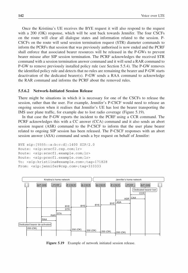
142 Voice over LTE
Once the Kristiina’s UE receives the BYE request it will also respond to the requestwith a 200 (OK) response, which will be sent back towards Jennifer. The four CSCFson the route will clear all dialogue states and information related to the session. P-CSCFs on the route will send session termination request (STR) diameter commands toinform the PCRFs that session that was previously authorised is now ended and the PCRFshall enforce that associated bearer resources will be released in the P-GWs to preventbearer misuse after SIP session termination. The PCRF acknowledges the received STRcommand with a session termination answer command and it will send a RAR command toP-GW to remove previously installed policy rule (see Section 5.5.4). The P-GW removesthe identified policy rule and detects that no rules are remaining the bearer and P-GW startsdeactivation of the dedicated bearer(s). P-GW sends a RAA command to acknowledgethe RAR command and informs the PCRF about the removed rules.
5.5.6.2 Network-Initiated Session Release
There might be situations in which it is necessary for one of the CSCFs to release thesession, rather than the user. For example, Jennifer’s P-CSCF would need to release anongoing session when it realises that Jennifer’s UE has lost the bearer transporting theIMS user plane traffic, for example due to lost radio coverage (Figure 5.19).
In that case the P-GW reports the incident to the PCRF using a CCR command. ThePCRF acknowledges this with a CC answer (CCA) command and it also sends an abortsession request (ASR) command to the P-CSCF to inform that the user plane bearerrelated to ongoing SIP session has been released. The P-CSCF responses with an abortsession answer (ASA) command and sends a bye request on behalf of Jennifer:
BYE sip:[5555::a:b:c:d]:1400 SIP/2.0Route: <sip:scscf2.csp.com;lr>Route: <sip:scscf1.example.com;lr>Route: <sip:pcscf1.example.com;lr>To: <sip:[email protected]>;tag=171828From: <sip:[email protected]>;tag=333333
S/P-GW S-CSCFP-CSCFPCRF P-CSCF S/P-GWPCRFS-CSCF
ASR CAA
CCR
ASA
Dedicated bearer lost
BYEBYEBYE
STR
STA
RAA
Dedicated bearer de-activated
BYE
RAR
200 (OK) 200 (OK) 200 (OK) 200 (OK) 200 (OK)
Kristiina’s home network Jennifer’s home network
Figure 5.19 Example of network initiated session release.

VoLTE End to End and Signalling 143
There may be occasions when Kristiina’s S-CSCF needs to be shut down or Kristiinamay be using a pre-paid card and runs out of money. In such cases Kristiina’s S-CSCFwould release the session by issuing one BYE request towards Kristiina’s UE:
BYE sip:[5555::a:b:c:d]:1400 SIP/2.0Route: <sip:pcscf1.example.com;lr>To: <sip:[email protected]>;tag=171828From: <sip:[email protected]>;tag=333333
and another bye request towards Jennifer’s UE:
BYE sip:[5555:1:2:3:4]:1600 SIP/2.0Route: <sip:scscf2.csp.com;lr>Route: <sip:pcscf2.csp.com;lr>From: <sip:[email protected]>;tag=171828To: <sip:[email protected]>;tag=333333
To generate the BYE request with the correct set of Route headers, the P/S-CSCFsneed to keep track of all routing information that is collected during the establishment ofany dialogue.
5.5.7 Related Standards
Specifications relevant to Section 5.6 are:
• 3GPP TS 23.203 – Policy and charging control architecture.• 3GPP TS 23.218 – IP multimedia (IM) session handling; IM call model.• 3GPP TS 23.228 – IP multimedia subsystem (IMS); stage 2.• 3GPP TS 24.173 – IMS multimedia telephony service and supplementary services.• 3GPP TS 24.229 – IP multimedia call control protocol based on session initiation pro-
tocol (SIP) and session description protocol (SDP); stage 3.• 3GPP TS 24.930 – Signalling flows for the session setup in the IP multimedia core net-
work subsystem (IMS) based on session initiation protocol (SIP) and session descriptionprotocol (SDP); stage 3.
• 3GPP TS 26.114 – IMS multimedia telephony; media handling and interaction.• 3GPP TS 29.212 – Policy and charging control over Gx reference point.• 3GPP TS 29.213 – Policy and charging control signalling flows and quality of service
(QoS) parameter mapping.• 3GPP TS 29.214 – Policy and charging control over Rx reference point.• 3GPP TS 32.260 – Telecommunication management; charging management; IP multi-
media subsystem (IMS) charging.• 3GPP TS 32.299 – Telecommunication management; charging management; diameter
charging applications.• RFC2833 – RTP payload for DTMF digits, telephony tones and telephony signals.• RFC3261 – SIP: session initiation protocol.• RFC3262 – Reliability of provisional responses in the session initiation protocol (SIP).

144 Voice over LTE
• RFC3264 – An offer/answer model with SDP.• RFC3311 – The session initiation protocol (SIP) update method.• RFC3312 – Integration of resource management and session initiation protocol.• RFC3323 – A privacy mechanism for the session initiation protocol (SIP).• RFC3325 – Private extensions to the session initiation protocol (SIP) for asserted iden-
tity within trusted networks.• RFC3455 – Private header (P-header) extensions to the session initiation protocol (SIP)
for the 3rd generation partnership project (3GPP).• RFC3550 – RTP: a transport protocol for real-time applications.• RFC3551 – RTP profile for audio and video conferences with minimal control.• RFC3556 – SDP bandwidth modifiers for RTCP bandwidth.• RFC3840 – Indicating user agent capabilities in the session initiation protocol (SIP).• RFC3841 – Caller preferences for the session initiation protocol (SIP).• RFC4566 – SDP: session description protocol.• RFC4596 – Guidelines for usage of the session initiation protocol (SIP) caller prefer-
ences extension.• RFC5279 – A uniform resource name (URN) namespace for the 3rd generation part-
nership project (3GPP).• http://www.3gpp.org/tb/Other/URN/URN.htm – URN values maintained by 3GPP.• RFC6050 – A session initiation protocol (SIP) extension for the identification of
services.
5.6 Voice Continuity
5.6.1 PS-PS Intersystem Handover
In future there will come also IMS VoIP over HSPA, which means that the IMS VoIP capa-ble terminal is able to move between LTE and HSPA accesses over the packet switchednetwork during a VoIP call. For seamless handovers the network and UE must supportpacket switched handover (PS HO) where the network makes handover preparation beforethe actual inter-system change.
3GPP has specified two inter system mobility variants, Gn and S3 based on the usedinterfaces between MME and SGSN. Both variants offer an optimised inter-system PShandover from LTE to 3G (and vice versa). When PS HO is used the handover delayand data transfer interruption time are minimised as the handover preparation is donebefore the execution.
The PS handover procedure can also be used with CSFB or with SRVCC. When PSHO is done with CSFB it reduces a voice call setup time because the time needed for theaccess change is minimised. You can find more about CSFB in Sections 4.3.2 and 5.8.
For SRVCC the MME makes bearer splitting. The MME signals voice media bearerinformation to the MSC and all other bearers to the SGSN. The PS HO can be usedfor the MME-SGSN signalling to reduce a PS bearer handover delay. A more detailedSRVCC description is in Section 5.6.2.
The PS-PS handover is usually explained in two phases: handover preparation andhandover execution. Figure 5.20 gives a high level description how handover preparation

VoLTE End to End and Signalling 145
MME
BSC
RNC
RAN
2G
3G
LTE
EPC
S/P-GW
Services in PacketData Network
Internet
IMSServices
CorporateServices
1
2
SGSN
Figure 5.20 E-UTRAN to UTRAN PS-PS handover.
is done between the LTE eNodeB and 3G radio network controller (RNC), and corenetwork signalling goes over an S3 interface between MME and SGSN.
1. The PS-PS VoIP handover from LTE to UTRAN is done so that ongoing IMS signallingbearer and VoIP media bearer are moved from source access to the target access byestablishing corresponding bearers to the target access. In the handover preparationphase the target SGSN makes one-to-one mappinng from the EPS bearers to PDPcontexts. The SGSN makes also mapping between the EPS Bearer QoS parametervalues and the UTRAN QoS parameter values of a PDP context as shown in Figure 8.3in Chapter 8. The target RNC allocates the resources for the voice call and returns theapplicable parameters to SGSN, which responses to MME.
2. In the handover execution the MME sends a handover command to eNodeB includingthe bearer information. The eNodeB commands the UE to make handover to the targetaccess network and handover execution is completed in the target side. After successfulhandover the MME starts releasing bearers on the source side.
5.6.2 Single Radio Voice Call Continuity
Another flavour to provide session continuity in VoLTE is to perform transfer of ongoingvoice call from LTE (EPS/IMS domain) to circuit switched domain in case native VoIPconnection no longer can be maintained in LTE. This procedure is standardised undername SRVCC but also known as packet switched–circuit switched (PS-CS) access domaintransfer. The overall behaviour of VCC is based on principles defined in 3GPP Release7 (voice call continuity) and further enhanced in 3GPP Release 8 in order to supportnetwork-initiated behaviour triggered by the access network. Additionally SRVCC hasbeen defined in 3GPP Release 8 for both VoIP sessions started in UTRAN and in LTEbut practical implementations can also be done only for LTE if so required.

146 Voice over LTE
UTRAN/GERAN
E-UTRAN
Circuit switched
Packet switchedInternet (IP) traffic
VoiceIMS signalling
IP multimediasubsystem
Voice
SRVCCdirection IMS signallingInternet (IP) traffic
Figure 5.21 High level principle of single radio voice call continuity.
Figure 5.21 represents the high level idea of this procedure. The voice part of com-munication between UE and network is transferred from LTE to CS whereas othercommunication is maintained via the PS core.
The domain transfer consists at high level both moving the voice bearer from EPS tocircuit switched domain but also moving related packet switched connection by using,for example PS handover procedure in parallel to the target radio access technology suchas 3G.
In order to support SRVCC at system level specific new functionalities are required intonetwork architecture. First of all new interworking functionality is defined as a SRVCCenhanced MSC server that is able to perform required procedures towards circuit switcheddomain to ensure that target radio access is prepared and ready for access domain transfer.Additionally EPS need to be enhanced, namely MME and evolved NodeB (eNb) to supportsuitable procedures to trigger domain transfer and eventually also move related packetswitched EPS bearers besides the voice connection to the target access domain.
In order to support access domain transfer, the SRVCC enhanced MSC server hasspecific GPRS tunnelling protocol (GTP) based Sv-interface towards MME. This Svinterface as defined in (3GPP TS 29.280) is used by MME to request the MSC server toreserve required radio access resources from target CS radio access (GERAN/UTRAN)for SRVCC. Role of the SRVCC enhanced MSC server is twofold. First of all it isresponsible to prepare resources towards IuCS or A interface either controlled by samenetwork element or alternatively in case target radio access is controlled by anotherMSC Server (MSC-B), perform the normal inter-MSC relocation as defined in (3GPP TS23.009). Secondly, after target CS radio access resources have been committed then theSRVCC enhanced MSC server will establish call on behalf of UE to a specific addressgiven by MME via the Sv interface. This address is related to current service centralisationand continuity (SCC) AS of that particular subscription and involved in the original callestablishment.
SRVCC procedure has been gradually improved since 3GPP Release 8 to supportmore functionality such as capability to support SRVCC for emergency calls, multiplesimultaneous calls which are active and held, for calls in ringing phase, for video callsas well as capability to perform SRVCC back from CS network to LTE. In order tosupport functionalities beyond 3GPP Release 8 additional requirements set by 3GPP ICS

VoLTE End to End and Signalling 147
IP multimedia subsystem
S/P GW
eNodeB
Evolved UTRAN
Evolved packet core
MME
SRVCC enhancedMSC Server &
MGCF
MGCF
MSC-B (MSC/MSC server)
HSS
BTS
Nb
BSC
GERAN/UTRAN
Sv
S1-MME
S1-U
IuCS
A
MAP
S6a IMS-MGW
Circuit switched networkenhanced SRVCC
SCC AS
P-CSCF I/S-CSCF
MAP
ISUP/BICC/SIP-I
Mj
Sh
Gm Mw
Ma/ISC
EISUPBICCSIP-I
SGSN
IuPS
Gb
Gr/S6d
S4
S3
S11
RNC
Figure 5.22 Network architecture for SRVCC.
architecture need to be taken into use. This can occur in a phased manner, in the casein which IMS-based voice over LTE has been deployed commercially by using 3GPPRelease 8 standardisation baseline, which is also covered more thoroughly in this book.
Figure 5.22 represents a 3GPP Release 8-based network architecture required to performSRVCC procedure.
In summary, certain relevant functionalities can be highlighted in this architecture forSRVCC access domain transfer execution:
• SRVCC enhanced MSC server:– Performs the task of preparing the target radio access side resources for immediate
domain transfer.– Provides the Sv interface towards EPC, which will be used to trigger domain transfer.– Acts as anchor MSC (MSC-A) for the CS handover connection towards target MSC
(MSC-B) in the case when inter-MSC handover occurs.– Updates the remote side of session after domain transfer.
• SCC AS:– Anchors the session during setup phase so that domain transfer can be later per-
formed, if required.– Performs access transfer from one domain to another.– Performs terminating access domain selection which is elementary procedure to route
terminating calls to a VoLTE subscriber.– Is able to remove media which is not allowed to continue after domain transfer.
• MME:– Indicates to eNb whether SRVCC is possible for this session.

148 Voice over LTE
– Is responsible to find right EPS bearer that will be subject for domain transfer.– Invokes SRVCC enhanced MSC Server via Sv interface and provides sufficient
information to complete the domain transfer procedure.– Performs relevant procedures to transfer non-VoIP bearers to target radio access
technology for instance by using PS HO, if applicable.– Handle suspend and deactivation of EPS bearer when needed.
• E-UTRAN eNodeb:– May generate a SRVCC specific neighbour cell list dynamically for target measure-
ment purpose– Is responsible to determine whether domain transfer needs to be performed.– Invokes MME to start domain transfer procedure via the S1 interface.– Invoke MME to start PS-HO in addition to PS to CS HO or just PS to CS HO
5.6.2.1 Execution of SRVCC
Let us use an already familiar example from earlier chapters of this book in order toclarify required the procedures to perform access domain transfer.
Let us assume that Kristiina and Jennifer have successfully established VoLTE sessionbetween themselves and are currently discussing a new fancy car that Kristiina has boughtduring the weekend. Kristiina is currently talking while driving (naturally using her Blue-tooth headset) to the countryside from the city centre and, since her favoured networkservice provider LTE coverage has not yet reached the countryside where she is driving,the network decides (based on measurement data received from her smartphone) that aneed for access domain transfer has appeared.
This starting point is shown in the Figure 5.23.The dashed line illustrates the path taken by the SIP during call establishment phase.
Services indicate both SCC AS and supplementary service (TAS) services but also otherservices may have been applied for the session. The solid line illustrates path taken bythe user plane (i.e. speech) connection to other side of VoLTE session. In this example itcarries voice between Jennifer and Kristiina. Finally the LTE UE typically also has manyother applications that are connected to Internet services (dotted line), which use need tobe able to continue after access domain transfer.
In order to start the access domain transfer procedure, we follow the flow shown inFigure 5.24 which describes the number of different signalling procedures that need totake place in order to securely transfer Kristiina’s call from LTE radio access to 3G radioaccess available in the countryside.
This PS to CS access domain transfer procedure is triggered by the eNb, which performsthis decision based on received measurements from UE. As a prerequisite, UE has anongoing IMS session and a related dedicated EPS bearer to IMS APN with GBR nature;then eNb, based on pre-configured triggering condition, is able to recognise which EPSbearers are subject for the access domain transfer and which EPS bearers will neednormal packet switched mobility towards target radio access network. The SR-VCC istypically triggered by UE event triggered measurements when the signal level [referencesymbol received power (RSRP)] or the signal quality [reference signal received quality(RSRQ)] drops below a predefined threshold. When eNodeB receives the measurementreport, it will initiate the SR-VCC procedure. In parallel to the SR-VCC procedure MMEwill also perform PS HO to GERAN/UTRAN since LTE attached UE has always at

VoLTE End to End and Signalling 149
IP multimedia subsystem
S/P GW
eNodeB
Evolved UTRAN
Evolved packet core
MME
MGCF
MSC-B(MSC/MSC server)
BTS
Nb
BSC
RNC
GERAN/UTRAN
Sv
S1-MME
S1-U
IuCS
A
IMS-MGW
Circuit switched networkenhanced with SRVCC
P-CSCF
ISUP/BICC/SIP-I
Gm
EISUPBICCSIP-I
Mg
Mw
CS-MGW
S/I-CSCF
Services
ISC
Mb
Internet
SGSN
S3
IuPS CS-MGWSRVCC enhanced
MSC Server &MGCF
S4
Figure 5.23 Initial situation before SRVCC.
least a default EPS bearer connection active. For more information about PS HO, seealso Section 5.6.1.
In order to recognise which EPS bearer(s) needs to be transferred as SRVCC and whichas PS HO, MME need to be aware that which EPS bearer has a voice component andwhich ones are dedicated for nonvoice use of those EPS bearers using the IMS APN.This is made possible with the use of 3GPP PCC architecture, as defined by (3GPP TS23.203), in such a way that P-CSCF will request PCRF to provide QoS in form of an EPSdedicated bearer with a GBR and QoS class identifier value 1 (Voice), see Section 5.5.4.The SRVCC is applicable only when the user has a dedicated bearer with QCI 1 and basedon this information the MME will pick the right EPS bearer from other active EPS bearers.
In the case where the target radio access technology is GERAN then the continuationof data connection after SRVCC requires the use of a dual transfer mode (DTM) featurein GERAN since otherwise ongoing GBR data bearers will be suspended for the durationof time and non-GBR data bearers will be released when UE is attached to GERAN andhas an ongoing call. In the case where the target radio access technology is UTRAN thenthe multi-radio access bearer (RAB) functionality of UTRAN ensures a continuation ofdata connection similar to today.
MME start to prepare resources towards target networks, which also include a circuitswitched domain in addition to a traditional packet switched domain since domain transferis required. Based on local configuration MME will select a SRVCC enhanced MSC serverhaving an Sv interface but also selects a target legacy packet switched network, namelySGSN, which MME then needs to contact via an S3 interface.
After this MME will send the following SRVCC PS to CS request message (Table 5.7) tothe SRVCC enhanced MSC server via the Sv interface which again will trigger reservationof the target CS network resources needed to perform domain transfer.

150 Voice over LTE
Mea
sure
men
tre
port
s
Han
dove
r re
quire
dP
S to
CS
HO
req
uire
d(c
odec
s, S
TN
-SR
, etc
)
Pre
pare
HO
req
uest
Pre
pare
HO
req
uest
resp
onse
Est
ablis
h sp
eech
conn
ectio
n
INV
ITE
to r
eque
st U
RI (
SC
C A
S a
ddre
ss)
(ST
N-S
R, c
orre
latio
n ID
)
PS
to C
S H
Ore
spon
se
Han
dove
r co
mm
and
Han
dove
r fr
omLT
E c
omm
and
Rel
ocat
ion
/ha
ndov
er c
ompl
ete
PS
to C
S H
Oco
mpl
ete/
Ack
Rel
ease
acc
ess
side
IMS
ses
sion
leg
Rel
ocat
ion
/ha
ndov
er c
ompl
ete
TM
SI r
eallo
catio
n
Sou
rce
eNb
Tar
get B
SC
/RN
CM
ME
SR
VC
C e
nhan
ced
MS
C s
erve
r/M
GC
FT
arge
t MS
Cor
MS
C s
erve
rT
arge
tS
GS
N
IMS
/S
CC
AS
Dom
ain
tran
sfer
dec
isio
n
PS
-HO
pro
cedu
re b
egin
s in
par
alle
l to
dom
ain
tran
sfer
SC
C A
S u
pdat
es o
ther
side
of I
MS
ses
ssio
n
Ter
min
al m
oves
to G
ER
AN
/UT
RA
N
Loca
tion
upda
te to
HS
S
PS
-HO
pro
cedu
re c
ompl
eted
Fig
ure
5.24
SRV
CC
sign
allin
gflo
w.

VoLTE End to End and Signalling 151
Table 5.7 Summary of SRVCC PS to CS request message
Name of parameter Purpose Example value/content
IMSI This parameter identifies the subscriberperforming the domain transfer.
Identifier of subscription (15digits long), includingmobile country code,mobile network code andactual mobile subscriberidentity number (MSIN).
SRVCC enhanced MSC Server uses thisafter successful domain transfer toperform location update to HSS.
Mobile equipmentidentity (IMEI)
This parameter is only present if domaintransfer will be performed withoutprior authentication or if UE isUSIMless. In other words it is trueIMSI is not available.
Identifier (16 digits long),containing eight-digittype allocation code(TAC) identifying theterminal model, six-digitserial number (SN) andtwo-digit softwareversion (SV).
This parameter is relevant in the case ofSRVCC for an emergency call.
Sv flags This parameter is used to indicatewhether the nature of a transferredsession is an emergency call or in thecase when the subscriber uses ICSservices.
EmInd = 0/1
ICS indication is received from HSS viaS6a interface by MME and isprovided to SRVCC enhanced MSCserver in this parameter.
ICS = 0/1
MME/SGSN Svaddress for controlplane
This parameter contains the IP addressused by MME to handle this domaintransfer.
Usable IP address, such as192.168.1.10
MME/SGSN SvTEID for controlplane
This parameter contains the tunnelendpoint identifier (TEID) value usedby MME to handle this domaintransfer. The same value is needed inGTP messages sent and received bynetwork elements related to thisdomain transfer procedure.
Unique identifier value,such as 123
C-MSISDN This parameter contains a unique addressthat identifies the end user and can beused for correlation purposes in SCCAS.
+3585012345678
In the case of an emergency call withoutprior authentication or using USIMlessUE then this parameter does not exist.
(continued overleaf)

152 Voice over LTE
Table 5.7 (continued)
Name of parameter Purpose Example value/content
STN-SR This parameter contains a sessiontransfer number for SRVCC.
+35850987654321
Parameter is received by MME fromHSS via S6a interface and uniquelyidentifies the SCC AS that has beenused to anchor all sessions of a givensubscriber.
MM context forE-UTRAN SRVCC
This parameter contains the requiredinformation from the source side of adomain transfer to the target side ofthe domain transfer in order toperform the domain transfer.
Encoding of mobile stationclassmarks (2/3) as wellas supported codec list isdefined in (3GPP TS24.008).
This parameter is only exchanged whena domain transfer is performed fromE-UTRAN to UTRAN/GERAN, thatis when SRVCC is performed forVoIP session over E-UTRAN.
Encoding of securityparameters (CKSRVCC,IKSRVCC, and eKSI) asdefined in (3GPP TS33.401) and (3GPP TS24.301).
Information included for instance:mobile station class marks, supportedcodec list, security parameters.
MM context forUTRAN SRVCC
This parameter carries the requiredinformation from the source side of adomain transfer to the target side inorder to perform a domain transfer.
Encoding of mobile stationclassmarks (2/3) as wellas supported codec list isas defined in (3GPP TS24.008).
This parameter is only exchanged whena domain transfer is performed fromUTRAN to UTRAN/GERAN, that iswhen SRVCC is performed for a VoIPsession over UTRAN.
Encoding of securityparameters (CK’CS,IK’CS, KSI’CS, Kc’,CKSN’CS) as defined in(3GPP TS 33.102) and(3GPP TS 24.008).
Information include for instance: mobilestation class marks, supported codeclist, security parameters.
Source to targettransparentcontainer
This parameter is transferred fromsource eNb/Nb transparently to targetNb/base transceiver station (BTS) viacore network.
When target radio accessnetwork is GERAN, thiscontainer contains oldbase station system (BSS)for the new BSSinformation element asdefined in (3GPP TS48.008).

VoLTE End to End and Signalling 153
Table 5.7 (continued)
Name of parameter Purpose Example value/content
It contains important information for thetarget radio access network to establishsufficient radio resources for thetransferred call.
When the target radioaccess network isUTRAN, this containercontains a source RNC totarget RNC transparentcontainer as defined in(3GPP TS 25.413).
Target RNC ID This parameter identifies the target RNC. As described in 3GPP TS29.002.
Target cell ID This parameter identifies the target cell. As described in 3GPP TS24.008.
Source (SAI) This parameter identifies the source ServiceArea Identifier (3G Cell) and is onlyvalid if the SRVCC is from HSPA.
As described in 3GPP TS24.008.
The Table 5.7 explains the relevant details of the SRVCC PS to CS request messagerequired to trigger domain transfer properly. This message has been specified in (3GPPTS 29.280) at stage 3 level.
Next the SRVCC enhanced MSC server will verify the ownership of the target RNC orbase station controller (BSC) based on the local configuration data (radio access networkconfiguration) and as result of this task will have the identity of the target MSC/MSCserver network element to which the handover will be performed. Two alternatives exist.In the case where target CS radio access is controlled by the same MSC server networkelement which acts as an SRVCC enhanced MSC Server then it locally prepares resourcestowards RNC or BSC. However in the case where inter-MSC relocation is needed withinthe scope of the SRVCC procedure, the SRVCC enhanced MSC server shall contact theMSC or MSC server that controls the target BSC or RNC via mobile application part(MAP) based e-interface (i.e. MSC-B) as in the case of inter-MSC handover today.
When the required resources have been reserved from the target circuit switched radioaccess network (UTRAN or GERAN) the SRVCC enhanced MSC server uses the sessiontransfer number for SRVCC (STN-SR) and routes the call towards the anchor functionalitythat resides within the IMS architecture, that is SCC AS that has anchored the IMS sessioninitially during the session establishment phase. This address, which uniquely identifiesthe network element in the home IMS network which previously anchored the givensession for a particular subscriber (in this case Kristiina), is obtained from HSS by MMEduring the LTE attachment phase and given via the Sv interface to an SRVCC enhancedMSC server as described earlier. STN-SR address allocation needs to be aligned at systemlevel to the IMS configuration (initial filtering criteria) since SCC AS selection duringoriginal call establishment, as described earlier, has been performed by using initial filtercriteria (iFC) stored in subscription data in the HSS.
Additionally the SRVCC enhanced MSC server contains uses the correlation mobilesubscriber international ISDN number (C-MSISDN) identifying the subscriber (Kristi-ina) that is the subject for the domain transfer and is received from MME via thePS-CS handover message. The SCC AS will use this C-MSISDN address to associate

154 Voice over LTE
the incoming session [via the media gateway control function (MGCF)] from the SRVCCenhanced MSC server to the already ongoing anchored IMS session. Additionally SCCAS will immediately update another side of the IMS session with a new local descriptorhaving a new IP address and port number that should be used for RTP and RTCP sessionsfrom this point onwards by another side of the IMS session (Jennifer’s UE). AdditionallySCC AS clears the SIP signalling connection towards UE that is performing the domaintransfer (Kristiina’s).
The IP address and port number given by SCC AS to the another side of connectionbelong to the MGW and which are sent by SRVCC enhanced MSC server within theSDP offer of a particular session transfer call routed by using the STN-SR address tothe SCC AS.
The following example represents the content of the invite sent by the SRVCC enhancedMSC server, also having in this example a MGCF role as integrated functionality (3GPPTS 29.163) and thus simplified for the sake of clarity. Only the relevant parameters areshown. In order to have a better understanding about the use of SIP in the context ofVoLTE, the reader is advised to read Section 5.5.
INVITE tel:+358040987654321 SIP/2.0P-Charging-Vector: icid-value="GseadArs+6OLdwdoiDKLoo=0412300";orig-ioi= example.home1.fiP-Asserted-Identity: tel:+358501234567
. . .Content-Type: application/sdpContent-Length: (. . .)
m=audio 49100 RTP/AVP 97c=IN IP6 5555::aaa:bbb:ccc:eeea=rtpmap:97 AMR/8000/1a=rtpmap:99 telephone-event/8000/1
The actual content of the message is similar to normal SIP session establishment withthe following exceptions:
• The INVITE request’s request URI contains a routable E.164 address of SCC AS thathas been retrieved via MME from HSS by the SRVCC enhanced MSC Server.
• The P-C-V is populated by the SRVCC enhanced MSC Server and is different from theone originally created for the session. This header is used for correlating the charginginformation in the post-processing system and therefore both the old and this new valueneed to be given together by SCC AS to the post-processing system in order to correlatethis session transfer call into the correct session.
• The P-asserted-identifier includes a correlation MSISDN address received via MMEfrom HSS by the SRVCC enhanced MSC Server and identifies the MSISDN of thesubscriber who currently has performed domain transfer (Kristiina in this example).
• The SDP contains the media description offer generated by the SRVCC enhanced MSCServer and MGW reserved for the given session transfer call.– The c-attribute contains the IP address of MGW.– The m-attribute contains the IP port number of RTP media of MGW.

VoLTE End to End and Signalling 155
– The individual speech codec(s) are listed in the priority order created based onthe supported codec list information that was received from MME in the PS-CShandover request.
The SRVCC enhanced MSC server having an integrated MGCF will receivean acknowledgement eventually from the serving IMS domain with the 200 OK(invite) message.
In the case where the SRVCC enhanced MSC server would not have an inte-grated MGCF then it is also possible to use a traditional circuit switched networknetwork–network interface (NNI) protocol such as ISDN user part (ISUP) or bearerindependent call control (BICC) to the route session transfer call via a separate MGCFto IMS/SCC AS. This issue depends on the capabilities of the equipment used.
It should be highlighted here that the complete SRVCC procedure consists ofpreparation and actual domain transfer phase. It is possible that the preparation phasehappens and the required bearer resources for domain transfer towards target CS networkare reserved but the actual domain transfer phase is not performed afterwards because forinstance the served UE has moved again back to a good LTE coverage or eNb cancelsthe HO request. However in the case where the domain transfer phase has been startedand SCC AS is contacted by an SRVCC enhanced MSC server then UE is moved toCS radio access. Reverse SRVCC is needed to perform domain transfer from CS to LTEradio access (this feature is being specified as part of 3GPP Release 11).
Finally when session transfer call establishment has been completed by an SRVCCenhanced MSC server towards SCC AS and no cancellation has been received from EPSthen the SRVCC enhanced MSC server will acknowledge MME that the required proce-dures has been completed by sending the SRVCC PS-CS complete notification messageto MME and prepare to receive a handover complete indication from target RNC or BSC(possibly via other MSC-B/MSC server-B) that UE has successfully moved to coverageof UTRAN or GERAN.
The SRVCC PS-CS complete notification message contains the information listed inTable 5.8.
Table 5.8 SRVCC PS-CS complete notification message
Name of parameter Purpose Example value/content
IMSI This parameter identifies thesubscriber performing thedomain transfer.
Identifier of subscription (15 digitslong) including mobile countrycode, mobile network code andactual mobile subscriberidentity number (MSIN).
SRVCC enhanced MSC serveruses this towards MME toidentify subscriber in question.
Private extension This parameter is optional and canbe used to transfer vendorspecific information betweennetwork elements.
Any

156 Voice over LTE
After handover complete has been received by the SRVCC enhanced MSC Server itmay perform re-allocation of a new temporary mobile subscriber identity (TMSI) for UEvia the circuit switched radio access network and it will perform the location updateprocedure towards HSS in order to inform HSS that the terminating circuit switched callsand short messages have to be sent to the subscriber via the SRVCC enhanced MSCserver. It should be noted that when the subscriber’s (Kristiina in this example) UE hasbeen also attached into the LTE via a combined EPS/IMSI attach procedure, that is hasbeen able to use CS fallback for EPS then the location update procedure performed bythe SRVCC enhanced MSC server will replace the VLR address of that particular MSCserver serving the SGs association for that given subscriber.
Figure 5.25 represents how call control signalling, user plane (speech) connection aswell as Internet-based applications are connected after domain transfer has been success-fully completed.
After domain transfer, the dashed line illustrates the call control signalling connectionvia a circuit switched domain to the serving IMS domain (SCC AS). In this particularexample the signalling connection is routed via the MSC-B (MSC server) controlling thecircuit switched radio access network (3G) via an SRVCC enhanced MSC server andseparate MGCF to the SCC AS located in the serving IMS domain. As described abovethe SCC AS has performed the inter-domain mobility with minimum impact to the remoteparty. The solid line illustrates the user plane (speech) connection that is now routed viacircuit switched access (MGWs) to the remote side of call. Finally also the IP traffic thatcontinues towards multiple active Internet-based applications after domain transfer viaUTRAN radio access and packet domain is shown with a dotted line from UE via Nb,RNC, SGSN and S/P GW to the Internet.
SGSN
IP multimedia subsystem
S/P GWeNodeB
Evolved UTRAN
Evolved packet core
MME
MGCF
MSC-B (MSC/MSC server)
BTS
Nb
BSC
RNC
GERAN/UTRAN
Sv
S1-MME
S1-U
IuCS
A
Circuit switched networkenhanced with SRVCC
P-CSCF
ISUP/BICC/SIP-I
Gm
EISUPBICCSIP-I
Mg
Mw
CS-MGW
CS-MGW
I/S-CSCF
Services
ISC
Mb
Internet
S3
IuPS
IMS-MGW
SRVCC enhancedMSC Server &
MGCF
S4
Figure 5.25 Signalling and media paths after SR-VCC.

VoLTE End to End and Signalling 157
As can be seen from the example, the domain transfer procedure for an ongoing VoLTEcall is rather complex one. Also the performance of this procedure depends on the way inwhich the involved network elements and UE are able to work together in the most optimalway to reduce the impact for ongoing call connection. The requirement for maximumspeech connection gap is defined in (3GPP TS 25.913) to be 300 ms. Above this it isexpected that end user experience will be degraded.
5.6.2.2 Evolution of SRVCC
Since the magnitude of SRVCC required standardisation as well as a number of require-ments it was divided into phases inside the 3GPP standardisation process.
The previously described basic functionality was completed within 3GPP Release 8 butthen other enhancements were introduced into 3GPP Releases 9, 10 and 11.
3GPP Release 9 introduces a specific ‘MSC server assisted mid-call’ functionalityin (3GPP TS 23.237) that is derived from the ICS enhanced MSC server functionalitydefined in (3GPP TS 23.292). This enhancement introduces a new SIP interface (i2) intothe SRVCC enhanced MSC server, which makes it possible to exchange session stateinformation directly between SCC AS and SRVCC enhanced MSC server, which is notpossible when, for example ISUP is used. This session information transfers the state ofthe ongoing sessions as known by the SCC AS to the SRVCC enhanced MSC server,making it possible that the SRVCC enhanced MSC server is then aware that the end userhad two ongoing sessions (one held and one active). Additionally the use of i2 enablescontrol of the conference session that was previously established in IMS by the servedUE (i.e. before SRVCC occurred).
Table 5.9 represents the end to end functionalities that are enabled by different 3GPPreleases within the scope of domain transfer procedure (SRVCC).
Figure 5.26 represents the 3GPP Release 10 level network architecture for domaintransfer constituting changes from previous releases. This architecture is shown inorder to achieve a better understanding about the differences between the 3GPPRelease 8 and 10 architectures. 3GPP Release 8 architecture was shown earlier in thissection.
The GSMA VoLTE (IR.92) profile mandates the Release 8 baseline, which means thatmost of the networks in the early phase will likely be compliant with that release. Howeverit is expected that networks will be enhanced to support a later 3GPP baseline eventuallyvia normal network evolution.
5.6.3 Summary
This section described an example of mobility management scenarios, which may beapplied for a VoLTE session when the UE moves between different kinds of 3GPP radioaccess network technologies.
The first part described mobility within two packet switched domains (3G/UTRAN andLTE/E-UTRAN), which can also be supported in the case when the legacy radio accesstechnology for 3G has been upgraded to support voice over IP with conversational trafficclass, robust header compression and other relevant technologies.
The second part described mobility between a packet switched domain (LTE/E-UTRAN) and a circuit switched domain. This mobility enables the operator to deploy

158 Voice over LTE
Table 5.9 SRVCC capabilities in 3GPP releases
3GPP release End to end capability Notes
Release 8 Domain transfer is supported onlyfor single active voice session.
This is currently selected as the baselinefor the GSMA VoLTE profile andtherefore it is expected that Release 8will be supported by all VoLTEnetworks at minimum.
Held sessions or sessions in thealerting phase are cleared andonly an active one is transferredto the circuit switched domain.
Release 9 In addition to the previous releasealso:
In order to support these capabilitiesenhancement for SRVCC an enhancedMSC server is needed. Thisenhancement is called the mid-callassisted MSC server (MaM), asdescribed earlier.
Held sessions and IMS based adhoc conference session aretransferred.
In addition to MaM also a newfunctionality is introduced into thenetwork architecture, called theemergency access transfer function(EATF) that is used to anchor theemergency session and which thenreceives the session transfer call fromthe SRVCC enhanced MSC server byusing the emergency session transfernumber for SRVCC (E-STN-SR).
Emergency sessions can betransferred.
Release 10 This release optimises the domaintransfer (SRVCC) networkarchitecture in order to reduceany possible speech path gap incase of roaming scenarios.
New functionalities are introduced intothe network architecture, called theaccess transfer control function(ATCF) and access transfer gateway(ATGW) which are both located in theserving network.
Anchoring of the session isperformed always in the servingnetwork in order to achieve this.
ATCF is responsible to handle theanchoring of the SIP session andATGW anchors the speech connectionalready at the beginning of a session(RTP/RTCP).
In addition, will also introducesupport for alerting phaseaccess domain transfer.
SRVCC enhanced MSC server willestablish a session transfer calldirectly to the ATCF, which again willcontrol the ATGW to switch thespeech path towards a MGW reservedby the SRVCC enhanced MSC server.This way another side of theconnection does not have to beupdated, as in the previous example.

VoLTE End to End and Signalling 159
Table 5.9 (continued )
3GPP release End to end capability Notes
Release 11 Support for reverse SRVCC fromGERAN/UTRAN to E-UTRAN.
Also CS originated calls from a VoLTEcapable UE require to be routed viaIMS in order to let SCC AS haveknowledge of these calls for apossible reverse SR-VCC.
SRVCC for video calls. SRVCC enhanced MSC server is alsoable to support domain transfer for CSvideo telephony, according to 3GPP3G-324M to LTE.
No major architectural improvementsbeyond Release 10.
IP multimedia subsystem
eNodeB
Evolved UTRAN
Evolved packet core
MME
ATCF
MSC-B (MSC/MSC server)
HSS
BTS
Nb
BSC
RNC
GERAN/UTRAN
Sv
S1-MME
S1-U
IuCS
A
MAP
S6a
ATGW
Circuit switched networkenhanced with SRVCC
EATFP-CSCF
Location retrievalfunction
MAP
SIPi2
Gm
SIP
EISUPBICCSIP-I
E-CSCF
Mw
IMS-MGW
CS-MGW
Mb
Mb
I/S-CSCF
Services
Ma/ISC
S/P GW
SRVCC enhancedMSC Server
with MaM/MGCF
Figure 5.26 SR-VCC 3GPP Release 10 architecture.
LTE by having a minimum impact to the other radio access technologies in place.However in this case, due the complexity of domain transfer procedure (SRVCC), itmay be that the initial VoLTE deployments are made without this feature. A targetstandardisation baseline for domain transfer is expected to be 3GPP Release 10 butinitial deployments may be done already using the 3GPP Release 8 baseline.

160 Voice over LTE
5.7 IMS Emergency Session
In the case of an emergency session special procedures are required to ensure that the userreceives special treatment in access, EPC and IMS domains.12 The following proceduresare performed during the IMS emergency session after the UE has detected an emergencysession request from the user (see also Figure 5.27):
• UE conducts RRC connection establishment with an emergency indication.• UE requests PDN connectivity with an emergency indication.• MME selects an emergency APN based on emergency configuration data and requests
the PDN GW to establish a default bearer. This is done in parallel to an existing PDNconnectivity to IMS APN.
• UE executes an IMS emergency registration using the received IP address and P-CSCFaddress. This registration is done in parallel to an existing regular registration.
• UE sends an emergency session request to IMS.• IMS routes the emergency session to a public safety answering point (PSAP) and
delivers the session information to PCRF.• The PCRF creates and delivers a policy rule to P-GW.• P-GW sets up a dedicated emergency bearer.
The description here covers the most typical use case where the UE is already regularlyregistered to the network. The detailed IMS function configuration such as E-CSCF andLRF can be found from Figure 3.17 (it also shows three different alternatives to reachPSAP). The emergency service is not a subscribed service and it is provided in the servingnetwork (in the roaming IMS network while the subscriber is roaming). The service canbe also provided without a valid USIM, ISIM or roaming agreement.
5.7.1 PDN Connection Setup for Emergency Session
The UE may make an initial attachment for an emergency session or the UE may requesta PDN connection for an emergency session.
When the UE is already attached to the MME it requests a new PDN connection for theemergency session by sending a PDN connectivity request NAS message to the MME.The MME has MME emergency configuration data (emergency APN, P-GW ID, APNAMBR and QoS profile, which includes ARP and QCI). The MME emergency config-uration data contain the emergency APN which is used to derive a P-GW, or the MMEemergency configuration data may also contain the statically configured P-GW for theemergency APN. The MME continues the procedure by sending a create session requestto S/P-GW.
The MME sends bearer setup request to the eNB including the ARP values foremergency bearer services indicate the usage for emergency services to the E-UTRAN.
12 In Finland 3 954 569 emergency calls were made in 2010 (http://www.112.fi/documents/Tilastoja_tammi-joulu_2011.pdf). This means 0,74 emergency calls per inhabitant annually.

VoLTE End to End and Signalling 161
PCRFeNodeB EPC IMS PSAP
RRC connection establishment(emergency)
EPS attachment and normal IMS registration
UE requested PDN connectivity (emergency)Authorization
policy rulesIMS emergency registration
INVITE (emergency)
PSAP selection
INVITE (emergency)
183 Session Progress183 Session
Progress
Session data Policy rules
Dedicated emergency bearer (QCI1) established
Rest of SIP signalling
Emergency session established
UE detectsemergency session
Figure 5.27 VoLTE emergency session.
After radio bearer setup the UE can use an emergency PDN connection for the SIPsignalling.
5.7.2 Emergency Registration
The UE has to perform the IMS emergency registration when the UE has a validUSIM/ISIM and the EPC has indicated it supports emergency specific functionalities aspart of EPS attachment or as part of tracking area updates and UE has detected that thesubscriber has dialled one of common emergency numbers, such as 911, 112.
The emergency registration procedure follows normal IMS registration procedures, asdefined in Section 5.4 with the exceptions described here.
The REGISTER request constructed by the UE contains a special ‘SOS’ parameterin the Contact header to indicate that this registration is for emergency purposes and theContact header does not contain feature tags for MMTel and SMS over IP. The emergencyREGISTER request using the new IP address would look like this:
REGISTER sip:ims.mnc005.mcc244.3gppnetwork.org SIP/2.0Via: SIP/2.0/UDP [5555::1:1:1:1]:1600; branch=0ueteMax-Forwards: 70

162 Voice over LTE
P-Access-Network-Info: 3GPP-E-UTRAN-TDD; utran-cell-id-3gpp=244051F3F5F7
From: <sip:[email protected]>;tag=3442fTo: <sip:[email protected] >Contact: <sip: [5555::1:1:1:1]:1600>;expires=600000;sos;+sip.instance="<urn:gsma:imei:90420156-025763-0>";Call-ID: herhe4636hdhfh3466Authorization: Digest username="[email protected]",
realm="ims.mnc005.mcc244.3gppnetwork.org", nonce="",uri="sip:ims.mnc005.mcc244.3gppnetwork.org",response=""
Security-Client: ipsec-3gpp; alg=hmac-sha-1-96; spi-c=1111;spi-s:=2222; port-c=9999; port-s=1600
Require: sec-agreeProxy-Require: sec-agreeSupported: pathCSeq: 10 REGISTERContent-Length: 0Content-Length: 0
This request gets routed to S-CSCF, and the request is challenged, and the UE respondsto the challenge as described in Section 5.4. When the S-CSCF receives the secondREGISTER containing a valid challenge response it will accept the registration but accord-ing to local regulation it sets the registration timer value (Expire header) to an emergencysession specific value. This value is expected to be much shorter than normal registration.The emergency registration should be active for the duration of emergency session and forsome time after session completion to allow PSAP to call back to the caller. Furthermore,the S-CSCF is not expected to set a Service-Route header as the emergency session isrouted from the P-CSCF to an emergency-call session control function (E-CSCF) not tothe S-CSCF.13 The 200 OK response would look like this:
SIP/2.0 200 OKVia: SIP/2.0/UDP icscf1.example.com;branch=3icteVia: SIP/2.0/UDP pcscf1.example.com;branch=2pcteVia: SIP/2.0/UDP [5555::1:1:1:1]:1600;branch=1ueteFrom: <sip:[email protected]>;tag=89797To: <sip:[email protected]>;tag=sgdewe3P-Associated-URI: <sip:[email protected]>, <tel:+358501234567>P-Charging-Function-Addresses: ccf=chargingentity.example.comP-Charging-Vector: orig-ioi: "Type1 example.com"; term-ioi:
"Type 1 example.com"Path: <sip:[email protected];lr>Contact: <sip: [5555::1:1:1:1]:1600 >;
expires=1000;sos;+sip.instance="<urn:gsma:imei:90420156-025763-0>";
Call-ID: herhe4636hdhfh3466
13 If a communication service provider desires to route a non roaming emergency session via S-CSCF then theS-CSCF adds a Service-Route header.

VoLTE End to End and Signalling 163
CSeq: 11 REGISTERContent-Length: 0
In contrast to a normal registration UE and P-CSCF do not subscribe to registrationevent package (Section 5.4.10). Furthermore, the UE or network are not allowed to executederegistration (Section 5.4.12). In other words the emergency registration stays active untilthe registration timer expires (here 1000 s). UE can, however, perform user-initiated emer-gency re-registration if the registration timer is about to expire when the UE is still engagedon an emergency communication or is in the process of initiating an emergency session.
5.7.3 Emergency Session
After the registration procedure the UE constructs an emergency INVITE request (requiredSDP information is not shown here; see Section 5.5.1 for SDP description).
INVITE urn:service:sos SIP/2.0Via: SIP/2.0/UDP [5555::1:1:1:1]:1600; branch=abc123Max-Forwards:70Route: <sip:[5555::55:66:77:88]:9000;lr>P-Access-Network-Info:3GPP-E-UTRAN-TDD;utran-cell-id-
3gpp=2440051F3F5F7P-Preferred-Identity: <tel:+358501234567>P-Preferred-Identity: <sip:[email protected]>Privacy: noneFrom: <sip:[email protected]>;tag=171828To: urn:service:sosCall-ID: cb03a0s09a2sdfglkj490333Cseq: 127 INVITERequire: sec-agreeProxy-Require: sec-agreeSupported: precondition, 100rel, 199Security-Verify: ipsec-3gpp; alg=hmac-sha-1-96; spi-c=98765432;
spi-s=87654321; port-c=8642; port-s=9000Contact: <sip:5555::1:1:1:1]:1600;Allow: INVITE, ACK, CANCEL, BYE, PRACK, UPDATE, REFER, MESSAGE,
OPTIONSAccept:application/sdp, application/3gpp-ims+xmlContent-Type: application/sdpContent-Length: (. . .)
This request looks pretty much like a normal INVITE request (Section 5.5.1). Thedifferences here are:
• Request-URI and To headers contain the emergency service uniform resource name(URN), which UE has translated from the dialled number (e.g. 112 or 911).
• The P-Preferred-Identity headers contain Kristiina’s registered IMS public user identi-ties (one SIP URI and one Tel URI).14
14 The P-Preferred-Identity header is mandatory for emergency sessions whereas it is optional for normal sessions.

164 Voice over LTE
• The Route header contains only address of P-CSCF.• Information related to the MMTel service are not present (the Accept-Contact and
P-Preferred-Service headers are not present and the Contact header does not containMMTel ICSI).
When this request arrives at the P-CSCF it will select an E-CSCF within the same IMSnetwork and routes the request to it. The E-CSCF will utilise the UE provided locationinformation (as transported in the P-Access-Network-Info header) and the UE providedemergency type (if provided, like sos.fire, sos.police) to resolve the PSAP address. Whenmore accurate location- or network-provided information is required then the E-CSCFwill use the LRF function (see Section 3.4.4.4) to obtain location information or to selectthe actual PSAP. The request is further routed to the PSAP and here on the session setupfollows the principles of a normal session setup.
If PSAP requires more accurate or updated location information from the caller it willsend a location request to the location retrieval function (LRF). The LRF will either usea secure user plane location (SUPL) standard defined by the Open Mobile Alliance orcontrol plane solution defined by 3GPP to obtain position information.
5.7.3.1 Related Standards
• 3GPP TS 23.167 – IP multimedia subsystem (IMS) emergency sessions.• 3GPP TS 23.401 – General packet radio service (GPRS) enhancements for evolved
universal terrestrial radio access network (E-UTRAN) access.• 3GPP TS 24.229 – IP multimedia call control protocol based on session initiation pro-
tocol (SIP) and session description protocol (SDP); stage 3.• 3GPP TS 29.212 – Policy and charging control over Gx reference point.• 3GPP TS 29.214 – Policy and charging control over Rx reference point.• RFC5031 – A uniform resource name (URN) for services.
5.8 CS Fallback for Evolved Packet System Call Case(s)
CS Fallback for EPS (CSFB) introduces capability to re-use existing circuit switchedcore network services as such while still enabling terminal to camp in LTE radio access.CSFB has been initially standardised in 3GPP Release 8 content and further enhancedin 3GPP Release 9 with number of improvements that are expected to increase end userexperience. The stage 2 specification defining the systemwide functionality of CSFB is(3GPP TS 23.272).
At a high level CSFB has been defined into multiple functionalities (use cases) thatcan be deployed separately based on the market need. These functionalities includethe following use cases as defined in the described 3GPP standardisation releases (inbrackets):
• Mobile originating SMS over LTE (3GPP Release 8);• Mobile terminating SMS over LTE (3GPP Release 8);• Mobile originating circuit switched voice and video telephony call (3GPP Release 8);• Mobile originating emergency call (3GPP Release 8);• Mobile originated priority call (3GPP Release 10);

VoLTE End to End and Signalling 165
• Mobile terminating circuit switched voice and video telephony call (3GPP Release 8);• Mobile originating call independent supplementary service procedure (3GPP Release 8);• Network initiated unstructured supplementary service data (NI USSD) (3GPP
Release 8);• Mobile terminating location request (MT-LR) (3GPP Release 8).
It is assumed that the initial deployments of CSFB are focusing on data-centric devices(probably tablets, USB dongles or similar form factors) that do not have integrated voicetelephony. Therefore initial use cases were centered on SMS and especially on how a shortmessage can be transferred from network to terminal for instance in order to configureactual terminal settings (device management) or deliver information about cost of dataservice (roaming bill shock prevention).
Both mobile originated SMS and mobile terminating SMS capability were part of theuse cases. In the long run native SMS over IP as defined by 3GPP, which is describedin Section 5.9.2.2, is expected to be taken into use with UEs that also support nativeIMS-based VoIP, but support for SMS over LTE with CSFB is also expected to be usedin parallel to this for a long time.
In order to support voice services in manner similar to that supported by mobile net-works today, it is assumed that user cases around mobile originating and terminating voiceand video telephony calls are made possible. This means that voice-centric devices havingan integrated telephony client (probably based on the handset form factor) which camp inLTE radio access are able to either originate or terminate calls by performing a fallback tolegacy radio access network which can be GERAN, UTRAN or CDMA2000 1x, in orderto complete the actual call. In fact such UE having voice-centric nature will not evencamp on LTE unless the core network does not provide suitable voice capable servicefor instance via CSFB. This means that it is expected that most networks will eventu-ally implement CSFB in order to successfully deploy voice service for LTE attached UEs.Therefore the speech path involved in an actual established call is always made via legacyradio access technology rather than via LTE. After the call has been completed then UEmoves back to coverage of LTE, if under sufficient coverage, or continues camping in the2G/3G cell. This is important in order to re-enable the benefits of LTE when possible.
The remaining call independent user cases, including location retrieval, may also berequired in some practical deployments. Especially USSD has many applications thatcontinue to maintain importance unless applications are re-implemented by using nativeIP technology. Such applications are for instance related to the use of pre-paid services.
In the long run the role of CSFB may gradually diminish in the network when VoLTEbased on IMS will be introduced and penetration of IMS capable terminals increase. Theintroduction of IMS-based VoIP may be done in a phased manner, meaning that in thefirst phase IMS-based VoIP is supported only when subscriber is within home publicland mobile network (PLMN) but when subscriber roams to other LTE network thenpure CS voice or CSFB will be used instead when native IMS roaming architecture isnot yet in place. Additionally in the case where the serving network does not supportan IMS-based emergency call or priority service as required by the local regulator thenthe operator may use CSFB for these services instead of IMS at beginning. This enablesgradual introduction of IMS-based VoIP depending on the business and technologicalcapabilities of network and UEs. The expected target architecture will be that emergencycall, multimedia priority service as well as roaming will be used based on IMS.

166 Voice over LTE
The remaining part of this subsection describes each user case in a more detailedfashion as well as describing the way that CSFB can be architecturally implemented intoa network. Additionally the main focus is on a 3GPP-based architecture and solutionwhereas it is expected that CSFB will have no significant role in 3GPP2 markets.
5.8.1 Architecture of CS Fallback for EPS
In order to implement CSFB capability to LTE deployment changes are required toboth the existing circuit switched network as well as the EPS. Possibly the most visiblechange is related to the introduction of a so-called SGs interface as defined in (3GPPTS 29.118) between MME serving LTE users capable of CSFB functionality and theMSC or MSC server of circuit switched networks. However the magnitude of changesrequired to circuit switched network depends on the selected approach, that is whetheran overlay deployment is used or not.
The CSFB functionality can be used in the case where UE, E-UTRAN and relevantcore network domains support the functionality. This means that there is no specifiedsubscription-level provisioning needed for CSFB in HSS/HLR but MME can reject arequest from the UE to perform combined IMSI/EPS attachment, if so configured. In caseEPS rejects combined IMSI/EPS attachment then in case of voice-centric LTE smartphone,when no IMS based voice service is available, it usually means that UE will camp onlegacy 3G/2G or CDMA technology.
Figure 5.28 represents a generic 3GPP network providing CSFB.In the architecture shown (Figure 5.28) the SGs interface is deployed to all such
MSC/MSC server network elements that provide GERAN/UTRAN service for same geo-graphical area rather than the E-UTRAN served by EPS. Additionally it is possible todeploy this functionality into MSC/MSC server network elements which are pooled as
Figure 5.28 Architecture for CS fallback.

VoLTE End to End and Signalling 167
described in (3GPP TS 23.236). In that case pooling mechanisms [the network resourceidentifier (NRI) part of TMSI] can be used to route signalling messages correctly to theright MSC/MSC server element in the pool after fallback has been performed. This kindof network architectural deployment is described in Figure 5.29.
As the configuration of SGs interface is the point to point connection between MMEsand MSC/MSC servers, it means that it is possible and fairly likely to design a networkin such a manner that a single MME is connected to multiple MSC/MSC servers and viceversa. In the case where a single MME is connected to multiple MSC/MSC servers theselection of MSC/MSC server can be based on mapping between the tracking areas servedby MME, old LAI received from UE and the location areas served by the MSC/MSCserver. It can be assumed that by default CSFB functionality for UEs within a singletracking area are handled by at least a single MSC/MSC server. However in the casewhere an increased network level resiliency is required then it is allowed by (3GPP TS23.272) that MME performs mapping of the location area from the tracking area in sucha way that multiple MSC/MSC servers are selected from a ‘pool’ of a configured list ofMSC/MSC servers. MME should follow principles defined in (3GPP TS 23.236), whichis also the basis for traditional circuit switched and packet switched pool functionality.According to this specification a specific IMSI hash functionality is performed for eachcombined IMSI/EPS attached UE during the attachment phase that results in the identityof the MSC/MSC server allocated to serve a particular UE.
Additionally the very first deployment of CSFB may be done in order to support onlySMS over LTE (SGs), for instance due to the reason that only data-centric devices areavailable commercially. In this case if no voice call or other use cases are required, thenthe network configuration in which MME is connected only to a few MSC/MSC Serverin network can be used without placing additional requirements to other network entities.This means that data-centric devices performing ‘SMS-only’ combined IMSI/EPS attachedto EPS can be easily served by a few overlay MSC/MSC servers since no actual fallbackis performed from one E-UTRAN to GERAN/UTRAN/CDMA2000 1x radio access.
However in the case where other user cases of CSFB are required, especially a mobileterminating call, then this kind of network deployment requires the use of a so-calledmobile terminating roaming retry (MTRR) functionality that was originally standardisedas part of (3GPP TS 23.018) and endorsed in (3GPP TS 23.272). This MTRR procedurewas originally standardised in order to solve problems caused by legacy circuit switchedmobile phones that hopped between the 2G and 3G radio access technology, causingterminating calls to fail (or forward to voice mail system) due to an unreachable condition.Re-use of MTRR in scope of CSFB requires that HLR and gateway MSC/MSC serversin home PLMN support this functionality. The same applies also to those networks fromwhere inbound roamers can roam to particular EPS and use CSFB. The MTRR procedureis described in more detail in Section 5.8.9.1.
Eventually the higher complexities involved in the deployment and use of MTRR(including end user experience penalties due to longer call establishment time as well asthe impact caused for network elements located in home PLMN) led to such a decisionthat the new procedure was proposed to be standardised as part of 3GPP Release 10,named mobile terminating roaming forwarding (MTRF). This procedure causes changesmainly to serving PLMN and removes the need to re-route calls from the home PLMNin the case where the serving MSC or MSC server changed during fallback procedure. Amore detailed description of this procedure is given in Section 5.8.9.2.

168 Voice over LTE
P-GWeNodeB
Evolved UTRANEvolved packet core
Gateway MSC /MSC server
SGs
S1-MME
S1-U S-GW
Packet data networks
SGs
CS CN
MSC /MSC server
BICC,SIP-I,ISUP
Pool oftwo MSC/MSC-S
SGs SGs
Pool oftwo MMEs
MMEMME
MSC /MSC server
Figure 5.29 CS fallback and pooling of network functions.
Figure 5.29 represents this network configuration which provides increased resiliencyagainst MSC/MSC server network element failures.
Finally, as also shown in Figure 5.29, it is also likely that MMEs are configured into a‘pool’ of MMEs that provide a service for a single tracking area in order to increase theresiliency of EPS. This is so called S1-flex (pool).
5.8.2 Description of SGs Interface
The SGs interface defined in (3GPP TS 29.118) was standardised based on high levelprinciples of the Gs interface as specified in (3GPP TS 29.018) used today in manymobile networks to provide paging co-ordination for terminals capable for both PS dataand CS voice.
Despite the fact that underlying principles have been taken from Gs interface the SGsinterface is based on different design principles than Gs. SGs interface is first of all basedon a native stream control transfer protocol (SCTP) without a classical SS7 protocol layer[MTP3/signalling connection control part (SCCP)] whereas the Gs interface is based onSS7 routing principles. This means that the SGs interface is always directly establishedbetween the MME and the involved MSC/MSC server.
Figure 5.30 represents the protocol stack of the SGs reference point.

VoLTE End to End and Signalling 169
SGsAP
SCTP
IPv4/IPv6
Figure 5.30 Protocol stack of SGs reference points.
SGsAP represents the SGs application part that is the actual protocol payload for theSGs interface including message syntax and information element structure. SGsAP istransported over the SCTP which can support either multihoming for path protectionagainst backbone failures or only single homing functionality, depending on the capabili-ties available in the actual network elements. These SCTP associations are pre-configuredand taken into use via management actions performed to network the elements in ques-tion. The use of multihoming is a widely recommended functionality in order to provideincreased network level resiliency against IP connectivity failures. Finally both IPv4 andIPv6 are supported by the SGs interface but again deployment can be done in flexiblemanner depending on the capabilities of the actual network elements.
The SGs interface message syntax is based on traditional tag length value (TLV)encoding containing the actual message definition and well as mandatory and optionalinformation elements. Similarly the information element contains the same kind of TLVstructure.
SGsAP related messages are used by certain standardised procedures that are performedbetween MME and MSC/MSC server. Particular procedures may consist of exchangeof only single SGsAP message or alternatively it consist sequence of multiple SGsAPmessages. SGs protocol defines, for example the following procedures:
• Alert and UE activity indication;• EPS detach and IMSI detach;• Downlink unitdata and uplink unitdata;• Location update;• Paging;• MM information;• Reset and status.
Actual detailed encoding of these all these previously listed procedures is beyond thescope of this book. Relevant procedures are referenced in a later part of this chapter whenactual call flows are described. Additionally the interested reader is advised to investigate(3GPP TS 29.118) to get more familiar with actual protocol level details of the SGsinterface, as shown in Table 5.10.
5.8.3 Idle Mode Signalling Reduction and Use of CSFallback for EPS
In early LTE deployments due to spotty LTE coverage it may be required that the idle modesignalling reduction (ISR) feature in LTE is used. This functionality makes it possible

170 Voice over LTE
Table 5.10 SGsAP messages
SGsAP message Purpose
SGsAP-alert-ack Used by MME to acknowledge initiation of alert proceduretowards the MSC/MSC server
SGsAP-alert-reject Used by MME to reject initiation of alert procedure towardsthe MSC/MSC server
SGsAP-alert-request Used by the MSC/MSC server to request an alert procedurefrom MME
An alert request is needed since the mobility state of an EPSattached UE is logically divided between MME andMSC/MSC server. It means that the MSC/MSC server(VLR) does not have always up to date knowledge of thereachability of the EPS attached UE via an SGs interfaceand thus VLR need to request MME to inform itselfregarding this state.
SGsAP-downlink-unitdata Used by the MSC/MSC server to transfer transparentlydownlink short message service-related information (e.g.actual content of short message) towards the EPS.
SGsAP-EPS-detach-ack Used by the MSC/MSC server to acknowledge a successfuldetachment of UE from EPS either by MME or UE. Afterthis procedure the UE is no longer considered to have anSGs association.
SGsAP-EPS-detach-indication Used by MME to initiate EPS detach procedure towards theMSC/MSC server in order to close the SGs associationestablished prior this event.
SGsAP-IMSI-detach-ack Used by MSC/MSC server to acknowledge a successfuldetachment of the IMSI (UE) from EPS either by MME orUE. After this procedure the IMSI (UE) is no longerconsidered to have an SGs association.
SGsAP-IMSI-detach-indication Used by MME to initiate the IMSI detach procedure towardsthe MSC/MSC server in order to close an SGs associationestablished prior this event.
SGsAP-location-update-accept Used by the MSC/MSC server to acknowledge a successfullocation update of a particular IMSI to VLR by MME. Thisprocedure is triggered by a combined IMSI/EPS attachprocedure and establishes an SGs association. After thisprocedure the IMSI (UE) has an SGs association.
SGsAP-location-update-reject Used by the MSC/MSC server to reject a location updateprocedure towards MME. The outcome of this is that theIMSI (UE) is not considered to have successfully establishedan SGs association.
SGsAP-location-update-request Used by MME to initiate a location update procedure towardsthe MSC/MSC server. Successful execution of this procedureis a pre-requisite for any use of CSFB functionality.
It should be noted that an SGs interface does not use aperiodical location update procedure similar to the A/IuCSinterface.

VoLTE End to End and Signalling 171
Table 5.10 (continued)
SGsAP message Purpose
SGsAP-MM-information-request
Used by the MSC/MSC server to transfer mobility managementlayer information towards a UE attached into EPS.
This includes for instance network information, time zone(NITZ) information in order to synchronise the time of datefor the UE from the core network.
SGsAP-paging-reject Used by MME to reject a paging request from the MSC/MSCserver.
The outcome of this is that a terminating call, SMS, LCS orUSSD towards an EPS attached UE cannot be completed.
SGsAP-paging-request Used by the MSC/MSC server to request paging of a UE for aterminating call, SMS, LCS or USSD towards a UE attachedinto EPS.
The UE will be informed about this request by MME and inthe case where RRC connection does not yet exist (the UEis in EPS idle-mode) then such a connection is establishedby MME.
SGsAP-reset-ack Used by MME or the MSC/MSC server to acknowledge asuccessful outcome of a reset procedure initiated by anothernetwork element.
SGsAP-reset-indication Used by MME or the MSC/MSC server to inform the otherside of an SGs interface that a particular network elementhas been restarted and the SGs association data hasbeen lost.
This will cause UEs to be unreachable for any terminatingrequests (paging) until the SGs associations are againestablished by performing a location update procedure. Thetrigger for such a location update may be for instance aperiodical tracking area update performed by an EPSattached UE.
SGsAP-service-request Used by MME towards the MSC/MSC server as a response toa paging request via SGs in order in order to inform thatMME has successfully established a radio signallingconnection towards UE and a terminating request canproceed.
This message resembles an acknowledgement to a pagingrequest even though named differently.
SGsAP-status Used either by MME or the MSC/MSC server as a result of arecognised protocol syntax error from any received message,which can be for instance:
Unknown message which is not recognised by recipient butignored;
Missing mandatory information element:Syntactically or semantically incorrect information element
received.SGsAP-TMSI-reallocation-
completeUsed by MME to indicate towards the MSC/MSC server of a
successfully performed TMSI reallocation via an SGsinterface.
(continued overleaf)

172 Voice over LTE
Table 5.10 (continued)
SGsAP message Purpose
SGsAP-UE-activity-indication Used by MME to indicate towards the MSC/MSC server that anEPS attached UE has performed some activity withinreallocation via an SGs interface and is reachable for instanceto receive a short message.
SGsAP-UE-unreachable Used by MME to indicate towards the MSC/MSC server thatEPS has not been able to reach a targeted UE as the result ofa paging request via SGs.
This procedure may result in the activation of an alert procedureby the MSC/MSC server in order to deliver succeedingactivity indications from MME to MSC/MSC server.
SGsAP-uplink-unitdata Used by MME to transfer transparently uplink short messageservice related information (e.g. actual content of shortmessage) towards the MSC/MSC server.
SGsAP-release-request Used by the MSC/MSC server (VLR) towards MME in order toinform MME that no more network access stratum (NAS)messages are assumed to be transferred between VLR and UE.
that UE moves in idle-mode between different 3GPP radio access networks (2G/3G/LTE)having concurrent registration to both the serving SGSN and MME network elements.On the HSS side this is seen as a reduced amount of signalling procedures since mobilitybetween 3GPP-based radio technologies no longer causes as much signalling towardsHSS as would be required in the case where ISR is not used at network level.
Use of ISR requires that UE, serving 2G/3G and LTE network as well as HSS supportit. The network may enable or disable the use of ISR if required.
The downside in the use of ISR is related to negative side-effects that will be causedby it for VoLTE and CSFB. In the case of CSFB it means that if ISR is supported for agiven UE in idle-mode having a combined IMSI/EPS attachment to LTE for CSFB thenMME shall need to forward paging request also towards SGSN in addition to sending itto eNb when this request is received via the SGs interface from the serving MSC/MSCserver. This is required due the fact that MME is not able to determine whether the UEwill be reachable via LTE or legacy 2G/3G radio access technologies.
5.8.4 Idle Mode versus Active Mode UE with CSFallback for EPS
In similar fashion as today the LTE attached UE’s EPS connection management(EMMECM) state in a packet switched domain is not known in detail by the servingMSC or MSC server providing circuit switched services for UE within circuit switcheddomain. This information is not provided to the circuit switched domain via theSGs interface and only MME or SGSN network elements have knowledge of this.Additionally due to this reason 3GPP has a specific non-EPS alert procedure whichcan be invoked by the MSC/MSC server (VLR) at any point in time to request via theSGs interface to EPS in order to be informed from events occurred in the EPS such

VoLTE End to End and Signalling 173
as EMMECM state change. This procedure is especially used with the SMS use case(SMS over SGs) where it is used to eventually inform the short message service centre(SMSC) that the UE is again reachable via EPS.
Naturally after a call has been established via a circuit switched domain then the MSCor MSC server has knowledge of the state of the UE as of today.
The reason why this issue is important is related to the fact that 3GPP CSFB relatedspecification defines a different kind of functional behaviour for EPS and UE dependingon the state of the UE related to fallback performed using CSFB procedures. In case ofSMS over SGs the UE state is not meaningful.
For the scope of this section the UE is considered to be in active mode when ithas ongoing data transfer towards core network for reason or another. The UE is againconsidered to be in idle mode when it does not have ongoing data transfer or radioconnectivity towards the core network.
In the case where the UE is in active mode then it has an ongoing radio resourceconnection with EPS and in this way is always considered to be reachable, thus pagingis not required. In case fallback is performed, then it is possible that the UE is eitherredirected with RRC release procedure towards 2G/3G or PS HO procedure is performedas defined in (3GPP TS 23.401) and described in Section 4.2.3. Additionally in this caseif the UE receives an incoming call from a circuit switched network then CSFB providesmeans for the network to identify the caller before fallback occurs by including a callingline identity parameter into the paging message that is sent towards the UE via the SGsinterface by the MSC/MSC server. Based on this information the called subscriber is ableto prevent fallback from occurring in the case where one does not want to receive the call.
In the case where the UE is in idle mode then in the case of an incoming, terminating cir-cuit switched call the serving MME needs to perform paging via the S1 interface to reachthe targeted UE subject for the call. Depending on the result of this paging procedure fall-back can be performed or rejected towards the MSC or MSC server that performed paging.
The following example call scenarios describe CSFB from both a mobile originatingcall in idle mode to 2G and a mobile terminating call in active mode to 3G using PS HOprocedure to move the ongoing data transfer to 3G.
5.8.5 CS Fallback Attachment
A prerequisite for the use of CSFB is that the UE has successfully performed combinedEPS/IMSI attachment into the serving EPS and CS core network. This attachment isa normal EPS initial attachment (see Section 5.3) with CS attach specific additions asdepicted in Figure 5.31.
1. The UE initiates an attachment as described in Section 5.3. The attach request messageincludes an indication for a combined EPS/IMSI attach and the MME allocates alocation area identity (LAI) for the UE.
2. The MME derives a VLR number based on the allocated LAI and on an IMSI hashfunction.
3. The MME sends a location update request (LAI, IMSI, MME name, location updatetype) message to the MSC/VLR.

174 Voice over LTE
S/P-GWeNodeB MME HSS MSC/VLR
1. EPS initial attachment steps 1-10 as described in Section 5.3
2. DeriveVLR
number
6. EPS initial attachment steps 11-18 as described in Section 5.3
3. Location Update Request (IMSI)
4. CSLocationupdate
5. Location Update Accept
Figure 5.31 Combined EPS/IMSI attachment into serving EPS and CS core network.
4. The MSC/VLR performs a subscription check for CS and performs a location updateprocedure in the CS domain.
5. The MSC/VLR sends a location update accept to the MME.6. The EPS attach procedure is completed by performing steps 11–18 as described in
Section 5.3.
5.8.6 Mobile Originating Call Using CSFB
A mobile originating call (normal, emergency or priority) for an idle or active mode UEconsists of a number of steps to move UE to 2G or 3G radio access and establish a voicecall in an appropriate manner to the called destination.
Figure 5.32 represents the mobile originating call establishment in idle mode.The CSFB procedure begins when triggered by the UE when it sends an extended
service request via a NAS connection as defined in (3GPP TS 24.301) to the serving MME.This message contains an indication that CSFB is requested as described in Table 5.11.
An example of the relevant parts of a S1 extended service request is shown below(except id-TAI and id-EUTRAN-CGI parameters).
S1AP-PDU: initiatingMessage (0)initiatingMessageprocedureCode: id-uplinkNASTransport (13)criticality: ignore (1)valueUplinkNASTransport
Item 1: id-NAS-PDUProtocolIE-Field

VoLTE End to End and Signalling 175
id: id-NAS-PDU (26)criticality: reject (0)value
NAS-PDU: XYZNon-Access-Stratum (NAS)PDU0010. . ..=Security header type: Integrity protected
and ciphered (2). . ..0111=Protocol discriminator: EPS mobility
management messages (7)Message authentication code: XYZ
0000. . ..=Security header type: Plain NAS message, notsecurity protected (0)
. . .. 0111 = Protocol discriminator: EPS mobilitymanagement messages (7)NAS EPS Mobility Management Message Type: Extended
service request (0x4c)0. . . . . . = Type of security context flag (TSC): Native security
context (for KSIasme) (0).000 . . .. = NAS key set identifier: (0). . .. 0000 = Service type: Mobile originating CS
fallback or 1xCS fallback (0)Mobile identity - M-TMSI - TMSI/P-TMSI (0x1234567)
Length: 51111 . . .. = Unused. . .. 0. . . = Odd/even indication: Even number of
identity digits. . ..100 = Mobile Identity Type: TMSI/P-TMSI (4)TMSI/P-TMSI: 0xc1234567
After this the MME will send a S1-AP INITIAL CONTEXT SETUP REQUEST pro-cedure towards serving eNB to inform eNb that the terminal has requested invocation ofthe CSFB procedure. In the case where the UE would be in active mode instead then amodification would be triggered by EPC towards the UE. The relevant parts for CSFB ofthe S1-AP INITIAL CONTEXT SETUP REQUEST message is encoded as described inTable 5.12.
An example of the relevant parts of S1 initial context setup request is shown below.
S1AP-PDU: initiatingMessage (0)initiatingMessageprocedureCode: id-initialContextSetup (9)criticality: reject (0)value
Item 1: id-CSFallbackIndicatorProtocolIE-Field
id: id-CSFallbackIndicator (108)criticality: reject (0)valueCSFallbackIndicator: cs-fallback-required (0)

176 Voice over LTE
Extended Service Request Extended Service Request
S1AP UE Initial Context Request withCSFB indicator and LAI
S1AP UE Initial Context Response
CM Service Request(CS Call)
CM ServiceReject
In case MSC / MSC serverhas changed
DTAP SETUP/EMERGENCY SETUP
DTAP CALL PROCEEDING IAM/INVITE
MSCServereNodeB MME HSS
GatewayMSC serverBSC/RNC
End user dials number
In this case since UE is in idle-modeno PS HO or redirect will be performed
UE performs fallback and moves to coverage of 2G/3G
CM ServiceRequest (CS Call)
CM ServiceReject
Location Update or combined RA/LA update
Call is established as regular Mobile Originated CS Call
Figure 5.32 Mobile originating call with CSFB.
Table 5.11 Content of extended service request
Name of parameter Purpose Example value/content
Extended servicerequest messageidentity
Identifies that the message is anextended service request
Value = 0×4C indicating anextended service request.
Service type This parameter identifies that anextended service request wasperformed due to a mobileoriginating fallback for EPS by UE.
Value = 0×00 indicating a mobileoriginating call related CSFBrequest.
Table 5.12 Content of S1AP initial context setup request
Name of parameter Purpose Example value/content
CS fallback indicator This parameter identifies that theserved UE has requested invocationof either a normal CSFB or apriority call related CSFB.
‘CSFB’ or ‘CSFB with highpriority’
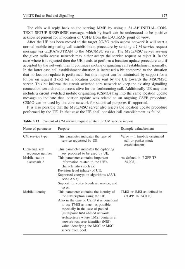
VoLTE End to End and Signalling 177
The eNb will reply back to the serving MME by using a S1-AP INITIAL CON-TEXT SETUP RESPONSE message, which by itself can be understood to be positiveacknowledgement for invocation of CSFB from the E-UTRAN point of view.
After the UE has been moved to the target 2G/3G radio access network it will start anormal mobile originating call establishment procedure by sending a CM service requestmessage via GERAN/UTRAN to the MSC/MSC server. The MSC/MSC server servingthe given radio access network may either accept the service request or reject it. In thecase where it is rejected then the UE needs to perform a location update procedure and ifaccepted by the network then it continues mobile originating call establishment normally.In the latter case call establishment duration is increased a bit compared to the situationthat no location update is performed, but this impact can be minimised by support for afollow on request (FoR) bit in location update sent by the UE towards the MSC/MSCserver. This bit informs the circuit switched core network to keep the existing signallingconnection towards radio access alive for the forthcoming call. Additionally UE may alsoinclude a circuit switched mobile originating (CSMO) flag into the same location updatemessage to indicate that location update was related to an ongoing CSFB procedure.CSMO can be used by the core network for statistical purposes if supported.
It is also possible that the MSC/MSC server also rejects the location update procedureperformed by the UE. In that case the UE shall consider call establishment as failed.
Table 5.13 Content of CM service request content of CM service request
Name of parameter Purpose Example value/content
CM service type This parameter indicates the type ofservice requested by UE.
Value = 1 (mobile originatedcall or packet modeestablishment)
Ciphering keysequence number
This parameter indicates the cipheringkey proposed to be used by UE.
Mobile stationclassmark 2
This parameter contains importantinformation related to the UE’scharacteristics such as:
As defined in (3GPP TS24.008).
Revision level (phase) of UE;Supported encryption algorithms (A5/1,
A5/2 A5/3);Support for voice broadcast service, and
so on.Mobile identity This parameter contains the identity of
the subscription using the UE.TMSI or IMSI as defined in
(3GPP TS 24.008).Also in the case of CSFB it is beneficial
to use TMSI as much as possible,especially in the case of pooled(multipoint Iu/A)-based networkarchitectures where TMSI contains anetwork resource identifier (NRI)value identifying the MSC or MSCserver from pool.

178 Voice over LTE
In this example scenario the UE does not perform location update prior to performinga mobile originating call since the location area served by MSC/MSC server has notchanged from the one that was used by the UE while connected to EPS.
Table 5.13 describes the content of the CM service request message relevant for callestablishment purposes as defined by (3GPP TS 24.008).
An example of the relevant parts of the CM service request message is shown belowwhen received from the A interface inside Direct Transfer Application Part (DTAP) mes-sage (i.e. fallback has been performed into GERAN).
GSM A-I/F DTAP - CM Service RequestProtocol Discriminator: Mobility Management
messages0000 . . .. = Skip Indicator: 0. . .. 0101 = Protocol discriminator: Mobility Management
messages (5)00. . ... = Sequence number: 0..10 0100 = DTAP Mobility Management Message Type: CM
Service Request (0x24)
Ciphering Key Sequence Number0. . . . . . = Spare bit(s): 0.000 . . .. = Ciphering Key Sequence Number: 0
CM Service Type. . .. 0001 = Service Type: (1) Mobile originating call
establishment or packet mode connection establishmentMobile Station Classmark 2Length: 3
. . .
After the connection management (CM) service request has been properly handled bythe network then the UE will send a SETUP message to start call control procedureswithin the MSC/MSC server in order to route the call towards the called destination. Thesetup message is transferred transparently over the GERAN/UTRAN between the UE andMSC/MSC server.
Table 5.14 Setup message
Name of parameter Purpose Example value/content
Bearer capability, low-layercompatibility andhigh-layer compatibility
This parameter indicates therequested service from the network.
Speech, G3 facsimile,3G-324M videotelephony, and so on
Called party BCD number This parameter identifies the calleddestination address.
E.164 address of calledparty
Supported codec list This includes a list of the supportedcodecs when the UE supports auniversal mobiletelecommunications system(UMTS).
Wideband (WB) AMR andnarrowband AMR

VoLTE End to End and Signalling 179
Table 5.14 represents a few selected parameters from the setup message which areimportant from a call establishment point of view.
An example of the relevant parts of the setup message is shown below whenreceived from the A interface inside a DTAP message (i.e. fallback has been performedinto GERAN).
GSM A-I/F DTAP - SetupProtocol Discriminator: Call Control; call related SS messages0. . . . . . = TI flag: allocated by sender.000 . . .. = TIO: 0. . .. 0011 = Protocol discriminator: Call Control;
call related SS messages (3)01. . ... = Sequence number: 1..00 0101 = DTAP Call Control Message Type: Setup (0x05)Bearer Capability 1 <Contains information about nature of call;
Speech, videoetc.>
Called Party BCD Number - (04012345678)Element ID: 94Length: 71. . . . . . . . . . . . = Extension: No Extension.000 . . .. = Type of number: unknown (0x00). . .. 0001 = Numbering plan identification: ISDN/Telephony
Numbering (Rec ITU-T E.164) (0x01)BCD Digits: 04012345678
Supported Codec ListElement ID: 64Length: 8System Identification (SysID): UMTS (0x04)Bitmap Length: 2Codec Bitmap for SysID 1<Supported codecs for UMTS>
System Identification (SysID): GSM (0x00)Bitmap Length: 2Codec Bitmap for SysID 2<Supported codecs for GERAN>
All call related supplementary and intelligent network-based end user services andcharging activity are performed by a circuit switched network normally as today. Alsoas visible in the example, call routing is performed by using existing NNIs (NetworkNetwork Interfaces), such as ISUP, BICC, SIP-I or native SIP as today [initial addressmessage (IAM)/invite message in the figure above].
After the call is disconnected, then as in the case of a mobile originating call, the UEwill perform idle-mode mobility based on instructions received from the serving radioaccess network and rules defined in (3GPP TS 23.221). Additionally it was later enhancedthat MSC/MSC Server is able to inform serving BSC/RNC that subscriber’s terminal has

180 Voice over LTE
performed fallback due CSFB. It allows BSC/RNC to recognize those UEs that can bemoved in more optimal way back to LTE. Also depending on capabilities of deployedsystem it may not be possible to transfer UE back to LTE sooner than all active PSconnections are torn-down.
Via these mechanisms it is assumed that the UE is instructed to select LTE radio accessas soon as possible, where coverage exists, in order to resume LTE end user experience.
5.8.7 Mobile Terminating Call Using CSFB
A mobile terminating call is a bit more complicated procedure than a mobile originatingone from a network point of view. In this case, since the terminal is indirectly attachedinto the serving MSC/MSC server, that is there is an existing SGs association between theMME and VLR of the MSC/MSC server, the UE needs to be paged via the SGs interfacetowards EPS in order to trigger the fallback procedure.
In this example the mobile terminating circuit switched call is routed to a LTE attachedUE in active mode, that is it has an ongoing packet switched connection via EPS. Thereforein addition to the fallback procedure a PS HO procedure will also be applied to move theterminal as swiftly as possible into target radio access to complete call establishment.
Figure 5.33 represents a mobile terminating call using CSFB in such a case when theMSC/MSC server is not changed during fallback.
Call establishment in the example above begins when the gateway MSC/MSC serverreceives an incoming call request (IAM or INVITE) from the originating network. Thismessage contains information about the nature of the request [transport medium require-ment (TMR) and user service information (USI)] as well as information about who (callingline identity) has called to whom (MSISDN of called subscriber).
Service Request
Paging response
DTAP SETUP
IAMINVITE(B#, CLI)Send Routing
Info (B#, MTRR)Provide RoutingInfo (MTRR)
Provide RoutingInfo Resp (MSRN)
Send RoutingInfo Resp (MSRN)
IAM/INVITE (MSRN, CLI)Paging(call,CLI)
Extended ServiceRequest (CSFB)
Paging(CS call,CLI)
Paging(CS call,CLI)
S1AP-UE Context ModificationRequest with CSFB indicator
S1AP-UE ContextModification Response
CS paging reject
DTAP CALL CONFIRMED
MSCservereNodeB MME HSS
GatewayMSC serverBSC/RNC
Allocate MSRN
Extended ServiceRequest (CSFB)
Packet switched handover for active data EPS bearers as describedin other parts of this book and 3GPP TS 23.401.
Paging response
Call is established as regular Mobile Terminated CS Call
Figure 5.33 Mobile terminating call using CSFB.

VoLTE End to End and Signalling 181
The gateway MSC/MSC server performs a HLR (HSS) enquiry as described in (3GPPTS 23.018) in order to retrieve a mobile station roaming number (MSRN) from the visitedMSC/MSC server having the SGs association for the called subscriber. This procedureuses send routing information message from the gateway MSC/MSC Server to HLR(HSS), which requests the MSRN from the VLR of the visited MSC/MSC server byusing the provide roaming number (PRN) procedure. In this example the capability touse the MTRR procedure is shown in the send routing information and PRN messagesin order to illustrate the way in which this capability is advertised between the gatewayMSC/MSC server and the visited MSC/MSC server. Without this indication the visitedMSC/MSC server shall not invoke the MTRR procedure.
Table 5.15 Content of SGsAP-paging-request
Name of parameter Purpose Example value/content
IMSI This parameter contains the IMSI ofthe subscription to which thispaging message is associated.
Identifier of subscription (15digits long), includingmobile country code, mobilenetwork code and actualmobile subscriber identitynumber (MSIN)
TMSI This parameter contains the TMSIallocated by the visited MSC/MSCserver (VLR) for the subscriber.
TMSI (possibly includingnetwork resource identifierin case CS CN uses pooling)
Calling line identity This parameter is sent by the visitedMSC/MSC server when callingline identification (CLI)presentation has not been restrictedby the caller.
E.164 address of calling party
In the case where the UE is in activemode then MME will send the CLIas part of a paging request to theUE via an S1 interface. Thisinformation can be used by thecalled subscriber to reject possiblefallback.
Service indicator This parameter identifies the reasonfor the paging procedure.
CS call or SMS
The reason can be either a CS call ora short message.
Location areaidentifier
This parameter includes informationabout the current location areaserved by the visited MSC/MSCserver.
Location area as encoded in(3GPP TS 24.008)
In case fallback occurs to a differentlocation area then the UE shallneed to perform a location updateprocedure before it can receive anincoming call.

182 Voice over LTE
Also not described in the figure both the gateway MSC/MSC server and HLR (HSS)can reside in a different network from the rest of the network elements. This is the caseif the called subscriber has roamed to another network and has performed a combinedIMSI/EPS attachment there.
After the call has been routed from the gateway MSC/MSC server to the visitedMSC/MSC server then the visited terminating services are executed by the visitedMSC/MSC server. These services include for instance blocking the identity of thecalling subscriber in the case where the calling line identity restriction service has beenrequested by the caller. Additionally the visited MSC/MSC server may perform late(conditional) call forwarding services such as forward call when the called subscriber isbusy in case such service needs to be invoked.
The paging procedure uses the SGsAP-PAGING-REQUEST message towards MMEfrom the MSC/MSC server (VLR). Table 5.15 represents some key parameters includedin the paging request.
An example of the relevant parts of SGsAP-paging-request message is shown below.
SGSAP Message Type: SGsAP-PAGING-REQUEST (0x01)IMSI - IMSI (234123456789012)
Element ID: 1Length: 80010 . . .. = Identity Digit 1: 2. . .. 1. . . = Odd/even indication: Odd number of identity digits. . ..001 = Mobile Identity Type: IMSI (1)BCD Digits: 234123456789012
VLR name – VLR1.MSS1.MNC01.MCC234.3GPPNETWORK.ORGElement ID: 2Length: 38VLR name: VLR1.MSS1.MNC01.MCC234.3GPPNETWORK.ORG
Service indicator - CS call indicatorElement ID: 32Length: 1Service indicator: CS call indicator (1)
TMSI - (0x200001)Element ID: 3Length: 4TMSI/P-TMSI: 0x00200001
Calling Party BCD Number - CLI - (358401234567)Element ID: 28Length: 80. . . . . . = Extension: Extended.001 . . .. = Type of number: International Number (0x01). . .. 0001 = Numbering plan identification: ISDN/Telephony
Numbering (Rec ITU-T E.164) (0x01)1. . . . . . = Extension: No Extension.00. . .. = Presentation indicator: Presentation allowed (0x00). . .0 00.. = Spare bit(s): 0. . ...11 = Screening indicator: Network provided (0x03)BCD Digits: 358401234567
Location Area Identification (LAI)Element ID: 4Length: 5

VoLTE End to End and Signalling 183
Location Area Identification (LAI) - 234/1/1000Mobile Country Code (MCC): United Kingdom of Great
Britain and Northern Ireland (234)Mobile Network Code (MNC): Unknown (1)Location Area Code (LAC): 0x0064 (100)
Global CN-IdElement ID: 11Length: 5Mobile Country Code (MCC): United Kingdom of Great
Britain and Northern Ireland (234)Mobile Network Code (MNC): Unknown (1)CN_ID: 100
eMLPP PriorityElement ID: 6Length: 10000 0. . . = Spare bit(s): 0x00. . ..111 = eMLPP Priority: Call priority level A (0x07)
After paging has been received by the UE then the MME will reply to the visitedMSC/MSC server with a SGsAP-SERVICE-REQUEST message acknowledging the startof the paging procedure and to inform that a NAS connection has been successfullyestablished with UE. Additionally the visited MSC/MSC server in this case is able tostart a call forwarding no reply timer and provide an audible ringing tone indicationtowards the caller.
Table 5.16 describes the relevant parameters of SGsAP-SERVICE-REQUEST message.An example of the relevant parts of SGsAP-SERVICE-REQUEST message is shown
below.
SGSAP Message Type: SGsAP-SERVICE-REQUEST (0x06)IMSI - IMSI (234123456789012)
Element ID: 1Length: 80010 . . .. = Identity Digit 1: 2. . .. 1. . . = Odd/even indication: Odd number of identity digits. . ..001 = Mobile Identity Type: IMSI (1)BCD Digits: 234123456789012
Service indicator - CS call indicatorElement ID: 32Length: 1Service indicator: CS call indicator (1)
Tracking area identityElement ID: 35Length: 5Mobile Country Code (MCC): United Kingdom
of Great Britain and Northern Ireland (234)Mobile Network Code (MNC): Unknown (1)Tracking area code(TAC): 0x0064
UE EMM modeElement ID: 37Length: 1UE EMM mode: EMM-CONNECTED (0)

184 Voice over LTE
Table 5.16 Content of SGsAP-service-request
Name of Purpose Example value/contentparameter
IMSI This parameter identifies thesubscription to which this messageis associated.
IMSI
Service indicator This parameter identifies the reasonfor the paging procedure.
CS call or SMS
The reason can be either a CS call ora short message.
IMEISV This parameter contains IMEI and asoftware version of the UE that isbeing paged.
Identifier (16 digits long)containing an eight-digittype allocation code (TAC)identifying the terminalmodel, a six-digit serialnumber (SN) and a two-digitsoftware version (SV)
UE time zone This parameter contains the time zoneof the UE as known by MME.
As described in (3GPP TS24.008)
This time zone can be different fromthe one used by the MSC/MSCserver in the case where it handlestime zones different from theMME.
Mobile stationclassmark 2
This parameter contains informationrelated to characteristics of the UE.
As described in (3GPP TS24.008)
Tracking areaidentifier
This parameter contains the lastknown tracking area identifier byMME.
As described in (3GPP TS23.401)
E-UTRAN cellglobal identity
This parameter contains detailedinformation about the last knownLTE cell of the UE known byMME.
As described in (3GPP TS23.401).
UE EMM mode This parameter indicates the currentEPS mobility management (EMM)mode of the UE when the pagingwas initiated by the MSC/MSCserver via an SGs interface.
EMM-connected
EMM-idle
The UE will reply to the received paging request (for an incoming CS call) by using anextended service request message towards the serving MME. This message also containsan indication whether the called subscriber has accepted or rejected the incoming CS callalready during the paging phase.
This enables the called subscriber to make a decision whether fallback occurs or not inthe case where the called subscriber has an ongoing important data session via LTE anddoes not want that to be disturbed. In the case where the called subscriber has rejected the

VoLTE End to End and Signalling 185
Table 5.17 Content of S1 AP extended service request
Name of parameter Purpose Example value/content
Extended service requestmessage identity
Identifies that message is extendedservice request
Value = 0×4C indicates anextended service request.
Service type This parameter identifies that anextended service request wasperformed due to amobileoriginating fallback for EPS byUE.
Value = 0 × 01 indicates amobile terminating call relatedCSFB request.
incoming call then MME will indicate this towards the visited MSC/MSC server by usinga SGsAP-PAGING-REJECT message including the SGs cause value ‘mobile terminatingCS fallback call rejected by the user’.
Table 5.17 describes important parameters in the extended service request message asdescribed in (3GPP TS 24.301) when the called subscriber has accepted an incoming callattempt.
An example of the relevant parts of the S1 AP extended service request message isshown below.
S1AP-PDU: initiatingMessage (0)initiatingMessageprocedureCode: id-uplinkNASTransport (13)criticality: ignore (1)value
UplinkNASTransport. . .Item 1: id-NAS-PDU
ProtocolIE-Fieldid: id-NAS-PDU (26)criticality: reject (0)value
Non-Access-Stratum (NAS)PDU0010 . . .. = Security header type: Integrity
protected and ciphered (2). . .. 0111 = Protocol discriminator: EPS mobility
management messages (7). . .0000 . . .. = Security header type:Plain NAS
message,not security protected (0). . .. 0111 = Protocol discriminator: EPS mobility
management messages (7)NAS EPS Mobility Management Message Type: Extended
service request (0x4c). . .. . .. 0001 = Service type: Mobile terminating CS
fallback or 1xCS fallback (1)CSFB response

186 Voice over LTE
1011 . . .. = Element ID. . .. 0. . . = Spare bit(s): 0x00. . ...01 = CSFB response: CS fallback accepted
by the UE (1)
Since the UE is in active mode while performing fallback it means that the MMEwill also need to configure the ongoing EPS connections towards eNb. In this case thisprocedure is started by sending a S1AP UE context modification request message towardseNB from the MME. The message is encoded as described in (3GPP TS 36.413). Thismessage contains also CS fallback indicator indicating to eNb that fallback will be soonperformed. eNodeb will reply to the MME with a S1AP UE context modification responseas acknowledgement for the request.
After this exchange of signalling messages has been completed between eNb and MMEthe EPS begins to move the active EPS bearer connections to the target radio accessnetwork (2G/3G). In this example it is assumed that PS HO is used towards 3G radioaccess technology. Execution of the PS HO procedure is described in Section 5.6.1. Inaddition to standard PS HO procedure eNb will inform the target RNC by using the sourceRNC to the target RNC transparent container that also CSFB has occurred. Also in thecase where a priority call is in question then that can be also indicated in the same wayto target the RNC.
When the UE has performed the fallback to target radio access (in this exampleUTRAN) then it will reply by sending a paging response via RNC to the visited MSC/MSCserver. In the case where the location area would be changed during the fallback proce-dure then the UE shall need to perform a location update to the visited MSC/MSC server,which also could have been changed. In this example it is assumed that the MSC/MSCserver and location area remains the same.
The visited MSC/MSC server will send a setup message towards the UE after receiv-ing the paging response. This setup contains sufficient information for the UE to haveinformation about the nature of the call. Also calling line identity is provided in orderto inform the called subscriber about the caller’s identity. Table 5.18 presents some keyparameters in the setup message as described in (3GPP TS 24.008).
An example of the relevant parts of SETUP message is shown below.
GSM A-I/F DTAP - Setup
Protocol Discriminator: Call Control; call related SS messages0. . . . . . = TI flag: allocated by sender.000 . . .. = TIO: 0. . .. 0011 = Protocol discriminator: Call Control;
call related SS messages (3)00. . ... = Sequence number: 0..00 0101 = DTAP Call Control Message Type: Setup (0x05)Bearer Capability 1 <Contains information about nature of
call: Speech, Video, etc.>. . .Calling Party BCD Number - (358040123456)
Element ID: 92Length: 8

VoLTE End to End and Signalling 187
0. . . . . . = Extension: Extended.001 . . .. = Type of number: International Number (0x01). . .. 0001 = Numbering plan identification: ISDN/Telephony
Numbering (Rec ITU-T E.164) (0x01)1. . . . . . = Extension: No Extension.00. . .. = Presentation indicator: Presentation allowed (0x00). . .0 00.. = Spare bit(s): 0. . ...11 = Screening indicator: Network provided (0x03)BCD Digits: 358040123456
The UE will reply to setup with a CALL CONFIRMED message by also indicating alist of supported speech codecs, which then is used by the visited MSC/MSC server toselect the appropriate speech codec for the call.
Finally the call is completely established between the caller and the called subscriber.After the call is disconnected, then as in the case of a mobile originating call, the UEwill perform idle-mode mobility based on instructions received from the serving radioaccess network and rules defined in (3GPP TS 23.221). Additionally it was later enhancedthat MSC/MSC Server is able to inform serving BSC/RNC that subscriber’s terminal hasperformed fallback due CSFB. It allows BSC/RNC to recognize those UEs that can bemoved in more optimal way back to LTE. Also depending on capabilities of deployedsystem it may not be possible to transfer UE back to LTE sooner than all active PSconnections are torn-down.
Via these mechanisms it is assumed that the UE is instructed to select LTE radio accessas soon as possible, where coverage exists, in order to resume LTE end user experience.
5.8.8 Call Unrelated CSFB Procedures
In addition to basic voice and video telephony use cases which utilise fallback from LTEto 2G/3G the 3GPP has also standardised the following non-call related procedures whichmay be required in practical CSFB deployments.
• Mobile initiated call-independent supplementary service procedure;• Network initiated call-independent supplementary service procedure;• Mobile originating location request (MO-LR) procedure;• Mobile terminating location request (MT-LR) procedure.
Table 5.18 Content of setup message
Name of parameter Purpose Example value/content
Bearer capability, low-layercompatibility andhigh-layer compatibility
This parameter indicates a servicerequested from the network.
Speech, G3 facsimile,3G-324M video telephony,and so on
Calling party BCD number This parameter identifies thecalling line identity of thecaller.
E.164 address of calling party

188 Voice over LTE
These procedures are all based on the same mode of operation in which the UE will per-form fallback from LTE to 2G/3G after which the actual procedure will then be performedvia the existing circuit switched core network. After the procedure has been completed,then the UE can re-attach into LTE by using idle-mode mobility principles defined in(3GPP TS 23.221) and if sufficient LTE coverage exists.
Both mobile and network initiated call-independent supplementary service proceduresare applicable when the UE wants to control supplementary service settings via atraditional UE user interface or when the network has supplementary service-specificinformation which need to be transmitted to UE. In the former situation this procedurecan be used for instance to activate a supplementary service, interrogate the state ofsupplementary service or deactivate a supplementary service. These procedures aredefined in (3GPP TS 24.010). It should be noted that when a terminal is capable forUt/XCAP interface-based service configuration then the UE shall need to use Ut/XCAPas the primary mechanism for that purpose.
In the case of a MO-LR procedure based on UE capabilities either fallback will beperformed or alternatively EPC procedures can be used instead to retrieve the currentlocation of the UE. The UE is able to determine whether EPC supports the EPC-MO-LRprocedure by checking the content of the location control services (LCS) support indicatorprovided during combined IMSI/EPS attachment phase from EPC. In the case where theLCS support indicator only indicates that the network supports the CS-MO-LR procedurethen the UE shall perform fallback to 2G/3G access to retrieve the location. In the casewhere the EPC-MO-LR procedure is supported or the UE has an ongoing IMS-basedvoice telephony session then the UE should avoid fallback procedure.
The MT-LR procedure is triggered by a gateway mobile location centre (GMLC) thathas received a request to retrieve the current location of a subscriber from the servingmobile network. In the case where the UE has performed a combined IMSI/EPS attach-ment and has registered to a circuit switched domain via EPS then HLR (HSS) has theVLR address of subscriber pointing to the MSC/MSC server having a SGs associationfor that particular subscriber. This SGs association, as defined in an earlier chapter ofthis book, is used to perform paging by sending a SGsAP-paging-request with an LCSindicator including that paging is due to a MT-LR procedure. Please see more detailsrelated to the content of the LCS identifier from (3GPP TS 29.118).
In all mobile terminating procedures previously described in this section, if the UEperforms fallback from LTE to 2G/3G and if the visited MSC/MSC server happens to bedifferent than one that performed original paging, then the procedure will fail. This is dueto the reason that 3GPP has not standardised any procedure similar to the ones describedin the next chapter which would re-route the mobile terminating procedure towards a newMSC/MSC server.
In today’s mobile networks external applications may also use MAP Any TimeInterrogation (ATI) procedure to interrogate current location of user. This ATI procedureis used towards HLR (HSS), which again uses MAP Provide Subscription Information(PSI) towards serving VLR respectively. Initially support for PSI in case user has activeSGs association was not defined by 3GPP. There has been recent proposals to enhancethis situation which are not described in more detail in this book. However issue need tobe taken into account when planning the deployment of CSFB in case such applicationsexists in network.

VoLTE End to End and Signalling 189
5.8.9 Mobile Terminating Roaming Retry and Forwarding
In the case when the UE performs fallback due mobile terminating call from LTE to 2G/3Gbut the target radio access network is controlled by a MSC/MSC server different from theone that originally performed the paging via the SGs interface towards EPS, then the UEshall perform a location update to the new MSC/MSC server, as described in Section 5.8.7.
This location update may contain a CSMT flag that indicates to the new MSC/MSCserver controlling the 2G/3G radio access network that a location update procedurehas been invoked during the ongoing fallback procedure. The CSMT flag in the newMSC/MSC server enables it to keep an existing signalling connection towards the UEopen for forthcoming call establishment from the gateway MSC/MSC server which isexpected to arrive shortly. In the case where CSMT is not supported either by the UE ora new MSC/MSC server then a new paging procedure need to be invoked and thus thecall establishment time will be longer than with a CSMT flag.
After location update has been performed properly then the HLR (HSS) of the calledsubscriber will cancel the subscription from the old MSC/MSC server by using a MAPCANCEL LOCATION message. In this case, depending on what kind of procedure issupported by the circuit switched network (both serving and home PLMN), then thefollowing events will happen.
5.8.9.1 Mobile Terminating Roaming Retry
In the case where the MTRR procedure is supported end to end as defined in (3GPPTS 23.018) and (3GPP TS 23.272) then the old MSC/MSC server will send a MAPRESUME CALL HANDLING (RCH) message towards the gateway MSC/MSC server.This message indicates that a MTRR procedure has been requested by the old MSC/MSCserver from the gateway MSC/MSC server. A prerequisite for the use of MTRR is that thegateway MSC/MSC Server has indicated the support for that procedure via HLR (HSS)to the old MSC/MSC server as described earlier (see Section 5.8.7). Sending of a MAPRCH message is triggered by the reception of a MAP cancel location from HLR (HSS).
In the case where the gateway MSC/MSC server decides to invoke a MTRR procedurethen it re-executes a new HLR enquiry towards HLR (HSS) in order to retrieve a MSRN,as described in (3GPP TS 23.018) and (3GPP TS 23.272). This is the second HLRenquiry that will be performed for the given call by the same gateway MSC/MSC servernetwork element. The gateway MSC/MSC server also releases ongoing IN dialoguesstarted from the gateway basic call state model (BCSM) and re-establishes those basedon a new HLR enquiry.
As the result of this procedure the call is re-routed from the gateway MSC/MSC serverto a new MSC/MSC server that controls the target 2G/3G radio access network to whichthe UE has performed fallback.
Figure 5.34 describes at high level the execution of a MTRR procedure.Use of this procedure requires that both the home PLMN as well as the serving PLMN,
if different, support the MTRR and a sufficient MAP version to transfer RCH messagefrom the old MSC/MSC server to the gateway MSC/MSC server. This may be a newrequirement for an inter-PLMN MAP interface. No support is required for MTRR pro-cedure from the target (new) MSC/MSC server that controls the 2G/3G radio access towhich the fallback was performed.

190 Voice over LTE
IAM
/INV
ITE
(B#)
Sen
d R
outin
gIn
fo (
B#,
MT
RR
)P
rovi
de R
outin
gIn
fo (
MT
RR
)
Pro
vide
Rou
ting
Info
Res
p (M
SR
N)
Sen
d R
outin
gIn
fo R
esp
(MS
RN
)
IAM
/INV
ITE
(MS
RN
)
Loca
tion
Upd
ate
(CS
MT
flag
)
DT
AP
SE
TU
P
Pag
ing
(cal
l,CLI
)P
agin
g(C
S c
all,C
LI)
Pag
ing
(CS
cal
l,CLI
)
DT
AP
CA
LL C
ON
FIR
ME
D
MA
P U
pdat
eLo
catio
n
MA
P C
ance
l Loc
atio
n
MA
P C
ance
l Loc
atio
n R
esp
MA
P In
sert
Sub
scrib
er D
ata
MA
P R
esum
e C
all H
andl
ing
(MT
RR
, cal
l ref
eren
ce)
MA
P R
esum
e C
all H
andl
ing
Ack
Cal
l cle
arin
g
2nd
Sen
d R
outin
gIn
fo (
B#)
2nd
Pro
vide
Rou
ting
Info
2nd
Pro
vide
Rou
ting
Info
Res
p (M
SR
N)
2nd
Sen
d R
outin
gIn
fo R
esp
(MS
RN
)
New
MS
CS
erve
reN
odeB
MM
EH
SS
Gat
eway
MS
C s
erve
rB
SC
/RN
CO
ld M
SC
Ser
ver
Allo
cate
MS
RN
CS
Fal
lbac
k fo
r E
PS
for
mob
ile te
rmin
atin
g ca
ll pe
rfor
med
. Pac
ket S
witc
hed
Han
dove
r fo
r ac
tive
data
EP
S b
eare
rs a
s de
scrib
ed in
oth
er p
arts
of t
his
book
and
3GP
P T
S 2
3.40
1.
Loca
tion
Upd
ate
(CS
MT
flag
)
Allo
cate
MS
RN
Cal
l is
esta
blis
hed
as r
egul
ar M
obile
Ter
min
ated
CS
Cal
l
MA
P U
pdat
e Lo
catio
n A
ck
Fig
ure
5.34
Mob
ilete
rmin
atin
gca
llus
ing
MT
RR
proc
edur
e.

VoLTE End to End and Signalling 191
Table 5.19 Content of MAP resume call handling
Name of parameter Purpose Example value/content
Call reference Identifies the call in question. Maximum string of eight octetslong byte.
All information sent This parameter indicates that allparameters are sent from the visitedMSC (VMSC) to the gateway MSC.
Presence of parameter fulfilsthe condition.
MT roaming retry This parameter indicates that thereason for sending MAP resume callhandling message was dueinvocation of MT roaming retryprocedure.
Presence of parameter fulfilsthe condition.
Table 5.19 describes the content of a MAP RCH message.Due the reason that the MTRR procedure requires wide support from circuit switched
networks, 3GPP has standardised another newer mechanism called mobile terminatingroaming forwarding as part of 3GPP Release 10. This procedure is more optimised in thesense that it only requires support for it from the serving PLMN and it has no impactfor the gateway MSC/MSC server. Additionally the call is no longer re-routed from thehome PLMN to the serving PLMN, causing a lower call setup time since the call can bere-routed entirely in the serving PLMN as described below.
5.8.9.2 Mobile Terminating Roaming Forwarding
The triggering event for the MTRF procedure is the same as with MTRR as describedabove and described in (3GPP TS 23.018).
After receiving the location update procedure from the UE that has performed thefallback procedure and in the case where the UE has indicated a CSMT flag in this proce-dure as described above then the new MSC/MSC server that controls 2G/3G radio accessnetwork indicates MTRF capability as part of a MAP SEND IDENTIFICATION messagetowards the old MSC/MSC server that performed the paging via SGs towards EPS.
After this the new MSC/MSC server also performs location update normally to HLR(HSS) which again cancels the subscription from the old MSC/MSC server as describedabove in case of MTRR. The old MSC/MSC server, also supporting a MTRF procedure,will send a MAP PRN message towards the new MSC/MSC server as a new functionalitythat is unique for the MTRF procedure. In this way the new MSC/MSC server will allocatea MSRN, as in the case of a normal HLR enquiry performed by the gateway MSC/MSCserver, and will provide it to the old MSC/MSC server in response. The old MSC/MSCserver will route the call directly to the new MSC/MSC server by using this numberwithin a serving PLMN, in this way optimising the call setup time as well as removingthe need to support re-routing via a gateway MSC/MSC server as would be case with theMTRR procedure.
Figure 5.35 describes at high level the execution of a MTRF procedure.The use of MTRF requires support from both the old and new MSC/MSC servers
located in the serving PLMN. This is a difference, compared to the MTRR in whichboth the old MSC/MSC server having a SGs interface and the gateway MSC/MSC

192 Voice over LTE
IAM
/INV
ITE
(B#,
CLI
)S
end
Rou
ting
Info
(B
#, M
TR
R)
Pro
vide
Rou
ting
Info
(M
TR
R)
Pro
vide
Rou
ting
Info
Res
p(M
SR
N)
Sen
d R
outin
gIn
fo R
esp
(MS
RN
)
IAM
/INV
ITE
(MS
RN
, CLI
)
Loca
tion
Upd
ate
(CS
MT
flag
)
Pag
ing
(cal
l,CLI
)P
agin
g(C
S c
all,C
LI)
Pag
ing
(CS
cal
l,CLI
)
MA
P U
pdat
e Lo
catio
n(M
TR
F s
uppo
rted
)
MA
P C
ance
l Loc
atio
n(M
TR
F s
uppo
rted
&au
thor
ized
,MS
C/V
LR n
umbe
r)
MA
P C
ance
l Loc
atio
n R
esp
MA
P In
sert
Sub
scrib
er D
ata
New
MS
CS
erve
reN
odeB
MM
EH
SS
Gat
eway
MS
C s
erve
rB
SC
/RN
CO
ld M
SC
Ser
ver
Allo
cate
MS
RN
CS
Fal
lbac
k fo
r E
PS
for
mob
ile te
rmin
atin
g ca
ll pe
rfor
med
. Pac
ket S
witc
hed
Han
dove
r fo
r ac
tive
data
EP
S b
eare
rs a
s de
scrib
ed in
oth
er p
arts
of t
his
book
and
3G
PP
TS
23.
401.
Loca
tion
Upd
ate
(CS
MT
flag
)
MA
P S
end
Iden
tific
atio
n (M
TR
F s
uppo
rted
, M
SC
/VLR
num
ber)
MA
P P
rovi
de R
outin
g N
umbe
r (M
TR
F in
dica
tion,
MS
C/V
LR n
umbe
r)
MA
P U
pdat
e Lo
catio
n A
ck
Allo
cate
MS
RN
Pro
vide
Rou
ting
Info
Res
p(M
SR
N)
IAM
/INV
ITE
(M
SR
N)
Loca
tion
Upd
ate
Ack
DT
AP
CA
LL C
ON
FIR
ME
D
Cal
l is
esta
blis
hed
as r
egul
ar M
obile
Ter
min
ated
CS
Cal
l
DT
AP
SE
TU
P
Fig
ure
5.35
Mob
ilete
rmin
atin
gca
llus
ing
MT
RF
proc
edur
e.
VoLTE End to End and Signalling 193
server network elements involved in call establishment process require support for theMTRR procedure.
Depending on whether the UE uses IMSI or TMSI while performing the location updateprocedure to a new MSC/MSC server then HLR (HSS) support is either required or not.In the case where the UE uses TMSI then HLR (HSS) support is not required for MTRFand a new MSC/MSC server can resolve the address of the old MSC/MSC server basedon TMSI. However in the case where the UE uses IMSI then a new MSC/MSC serverneed to indicate a requirement for MTRF to the MAP UPDATE LOCATION messagethat will be sent to HLR (HSS). HLR (HSS) needs to send this parameter to the oldMSC/MSC server in order to invoke the sending of a MAP PRN to the new MSC/MSCserver, as described in the Figure 5.35. Thus in the most optimal case UEs would alwaysuse TMSI as part of their location update procedure to a new MSC/MSC server and thenno HLR (HSS) support would be required.
In summary the mechanism to prevent the use of MTRF from a home PLMN is stan-dardised and therefore is likely to be implemented.
5.8.9.3 Co-Existence of MTRR and MTRF Procedures
It is also possible, due to the fact that MTRR and MTRF procedures can, in a phasedmanner, be independently introduced into different networks, that both procedures aresimultaneously available for use for the same call in both the home and serving PLMN.
Selection of the procedure call to be used will be based on the local O&M configurationand capabilities existing in the network elements in the serving PLMN.
5.8.10 Summary
This section describes CSFB functionality for EPS that enables the operator to re-useexisting circuit switched core network infrastructure to provide voice and SMS on top ofLTE data services.
It is expected that initial deployments for CSFB will be made for SMS cases buteventually also voice, video telephony as well as other use cases will be deployed intothe network. CSFB enables operators also to gradually migrate to IMS-based VoIP inparallel providing support for capabilities for use cases such as emergency call, roamingand priority call that may not be natively enabled at that time with IMS-based VoIP.Therefore it is highly expected that CSFB will be used in parallel to IMS-based VoIP,even with the same UEs. Also it may in some cases be the selected approach that SMSis still deployed by using CSFB procedures (SMS over SGs/LTE) even when the voiceand other services would be based on IP. Naturally in the long run it is expected thatIMS-based VoIP will be the only single technology in use but the transition period forthat may be long.
In addition to the basic call flow descriptions of example CSFB scenarios, this chapteralso describes different alternative technologies that can be used on the EPS side toperform fallback as well as to move active packet switched connections to the targetradio access network (2G/3G).
Finally radio access related details such as features that can be used to improve end toend performance can be found in Section 4.2.3.

194 Voice over LTE
5.9 VoLTE Messaging
Messaging services have been available for many years in mobile networks and havecontributed a significant deal of operator revenues coming directly from the servicesavailable in today’s mobile networks. According to some public studies, for instance inFinland, the number of short messages sent within the six month time period from January2010 to June 2010 was as huge as over 1900 million short messages sent (this means 700SMS annually per each inhabitant in Finland) whereas in same time period the number ofmultimedia messages was as high as 17 million messages (source: FICORA). The reasonto use Finland as an example was selected since Finland has the one of the highest mobilepenetrations in the world as well as one of the fastest reductions in the number of plainold telephony fixed access lines.
Operator provided messaging services are considered essential services in VoLTE forboth consumer and businesses, even though complementary technologies have been intro-duced since the introduction of SMS. These include instant messaging introduced as part ofthe rich communication suite and many Internet-based services such as Skype, MicrosoftMessenger or even more highly integrated solutions within UE messaging applicationssuch as Google Talk, Apple iMessage and What’s App services, which all are assumedto have significant impact to end user messaging behaviour. These services will probablygradually take over users from the more traditional short and multimedia messaging ser-vices (MMSs) but that will likely consume a lot of time, and the speed of this will varybased on markets.
Additionally one issue that reduces this movement towards pure-IP based messagingservices is related to the services that end users are able to use by using SMS today.It is possible for instance to order a bus ticket or to buy a bottle of lemonade by usinga short message and actual payment will be based on the end user’s mobile phone bill.This is a strong capability that cannot be easily replaced by Internet service providerssince instant messaging and other IP-based messaging applications have more often beenconsidered as free of charge services rather than trusted, payable services having a stronglocal connection to services close to subscribers.
In addition to basic short message and multimedia messages USSD has also beenincluded into this analysis, which is also being used widely today for a number of differentservice use cases such as topping up the pre-paid accounts, requesting dial-in from a homenetwork when roaming with a pre-paid subscription as well as controlling services in ahome network without a native phone user interface, to name a few examples.
5.9.1 Native IMS Messaging
Two different types of native IMS messaging forms exist: immediate messaging andsession-based messaging. Each form of IMS messaging has its own characteristics; so,even though messaging in its simplest form can be thought of as a single service – afterall, all forms of messaging are really about sending a message from A to B – the factthat these characteristics differ makes them each a service on their own. However, theway in which applications are built on top of these services may well hide the fact thatthese are different forms of messaging.

VoLTE End to End and Signalling 195
P/I/S-CSCF P/I/S-CSCF
MESSAGE MESSAGE MESSAGE
200 (OK)200 (OK)200 (OK)
Figure 5.36 Immediate messaging flow.
5.9.1.1 Immediate Messaging
Immediate messaging, or page-mode messaging, is the familiar instant messagingparadigm adopted in the IMS framework. It uses the SIP MESSAGE method to sendmessages between peers in near-real time. Figure 5.36 illustrates a typical messageflow. In immediate messaging, the UE simply generates a MESSAGE request, fills inthe desired content – which typically consists of text, but can also contain snippetsof multimedia such as sounds and images – and populates the Request-URI with theaddress of the recipient. The request is then routed via the IMS infrastructure similar tothe manner used for an INVITE (see Section 5.5.2), until the immediate message finds itsway to the UE of the recipient user or gets stored in the network. There might, of course,be a reply to this message; in fact, a full dialogue of immediate messages back and forthbetween the two users is likely. However, in contrast to session-based messaging, thecontext of this session only exists in the minds of the participating users. There is noprotocol session involved: each immediate message is an independent transaction and isnot related to any previous requests.
5.9.1.2 Session-Based Messaging
In this mode of messaging the user takes part in a session in which the main mediacomponent often consists of short textual messages. As in any other session a messagesession has a well-defined lifetime: a message session starts when the participants beginthe session and stops when the participants close the session. After the session is setup – using SIP and SDP between the participants – media then flows directly from peerto peer. Figure 5.37 illustrates the typical message flow of a message session. Session-based messaging can be peer to peer, in which case the experience closely mimics thatof a normal voice call. An ordinary invitation to a session is received, the only differ-ence being that the main media component is a session of messages. However, this isnot an actual limitation to session-based messaging, since it is, of course, possible tocombine other media sessions with message sessions. In fact, many useful and excitingapplications are enabled by this functionality: for example video calls with a text sidechannel might be a valuable application for hearing-impaired people. The actual protocolfor conveying the messages within a session is called the message session relay proto-col (MSRP) (RFC4975). MSRP layers on top of TCP, and can carry any multipurpose

196 Voice over LTE
P/I/S-CSCF P/I/S-CSCF
IMS session setup like shown in section 5.5
SEND
OK
SEND
OK
IMS session release as shown in section 5.5.6
Figure 5.37 Session-based messaging flow.
Internet mail extensions (MIMEs) encapsulated data. Messages can be of arbitrary size,since one of the protocol features is the ability to support sending a complete messagein small chunks that are automatically reassembled at the recipient end. Session-basedmessaging forms a natural unison with conferencing as well. Using the conferencingfunctionality, session-based messaging can turn into a multiparty chat conference.
In this mode of operation, session-based messaging can enable applications similar tomodern-day voice conferences. A service provider will typically offer the possibility forusers to have both private chats, where the set of participants is restricted and publicchats, some of which are maintained by the service provider. In this context the networktypically provides an additional functionality called MSRP switch. It is used to relaymessages between participants.
5.9.2 SMS Interworking
SMS has been a tremendous success in the past and still continues to be such in theLTE era. Lots of different services have been developed in such a fashion all across theglobe that use SMS as the enabling technology. Therefore continuation of this kind ofsuch service is extremely important for the LTE era as well. To deliver the actual SMSmessages to the UE in LTE access 3GPP has standardised two solutions: SMS over SGsand SMS over IP. In addition 3GPP has defined AS functionality to translate SMS toIMS immediate messaging and vice versa.
In both ways to provide SMS it is important to note that the common data model ofrelay layer protocol (RP) is used to transfer the actual short message payload even thoughthe transport is completely different (SIP protocol vs SGsAP/S1AP protocol). This isshown in Figure 5.38.
The CP-data message is transferred by using a short message control protocol (SM-CP)and is used in the CM layer to exchange an upper layer protocol such as short messagerelay protocol (SM-RP) and transfer protocol data unit (TPDU). RP-data messages aretransferred by using SM-RP used in the short message relay layer (SM-RL). The actual

VoLTE End to End and Signalling 197
SMS over SGs
SMS over IP
S1AP/SGsAP
RP-DataSM-CL (CP-Data)SM-RL (RP-Data)
SM-TL (TPDU)
SIP MESSAGE
SM-RL (RP-Data)
SM-TL (TPDU)
Figure 5.38 Protocol layers of SMS over SGs/IP.
application content of the short message is transmitted as a TPDU that is part of the shortmessage transfer layer (SM-TL).
More details of the protocol layer architecture for short message can be found from(3GPP TS 23.040) and (3GPP TS 24.011) specifications.
For example, in the case of SMS over SGs the CM layer is part of the transferredprotocol content in the SGs interface. In such a case the CP-data, CP-ack and CP-errormessages are embedded inside the NAS message container (3GPP TS 29.118).
The CP-data message embedded inside the NAS message container contains the fol-lowing parameters, as described in Table 5.20.
CP-data is acknowledged by the MSC server serving the given subscriber with theCP-ack message. Alternatively CP-error can be used to inform the UE of any error whichpossibly occurred during the procedure.
Table 5.20 Content of CP-data
Name of parameter Purpose Example value/content
Protocol discriminator This parameter contains a descriptionof the protocol payload included inthe CP-data.
Value ‘SMS messages’indicates the presence ofSMS payload.
Transaction identifier Identifies the transaction in questionbetween the two endpointsinvolved in messaging.
Value encoded as in (3GPPTS 24.007).
Message type Actual purpose of this message. Value can be eitherCP-DATA, CP-ACK orCP-ERROR.
CP-user-data Contains RP-data container. See Table 5.21 for contentof RP-data.

198 Voice over LTE
An example of a CP-data message is as follows.
GSM A-I/F DTAP - CP-DATAProtocol Discriminator: SMS messagesDTAP Short Message Service Message Type: CP-DATA (0x01)CP-User DataExtraneous Data
CP-user data contains the relay protocol data that contains an encapsulated RP-datamessage as defined below. RP-data is the first common message definition that is alsoused with SMS over IP as encapsulated inside the SIP MESSAGE payload.
In addition to RP-data, also RP-ack, RP-error and RP-SMMA messages have beenspecified in (3GPP TS 24.011). The RP-ack message is used for acknowledgement ofsuccessfully received RP-data whereas RP-error can be used to inform a peer entity thatRP-data has not been successfully processed. The RP-SMMA message is used by the UEto inform SMSC that the UE has again memory available to receive new short messages.
Table 5.21 contains a description of information encoded inside RP-data.An example of an RP-data message is as shown below.
GSM A-I/F RP - RP-DATA (MS to Network)Message Type RP-DATA (MS to Network)RP-Message ReferenceRP-Message Reference: 0x01 (1)
RP-Origination AddressLength: 0
RP-Destination Address - (358401234567)Length: 71. . . . . .. = Extension: No Extension.001 . . .. = Type of number: International Number (0x01). . .. 0001 = Numbering plan identification: ISDN/Telephony
Numbering (Rec ITU-T E.164) (0x01)BCD Digits: 358401234567
RP-User DataLength: 16TPDU (not displayed)
The TPDU container is transferred transparently between UE and SMSC. Dependingon the type of TPDU it can include one of the following protocol messages, according toTable 5.22.
The scope of this section covers important messages such as SMS-DELIVER andSMS-SUBMIT with the respective acknowledgement message, which are represented inthe following tables.
In the case where the UE originates the short message, then SMS-SUBMIT is encodedby the UE as shown in Table 5.23.
In the case where the UE receives the short message then the originating SMSC willsend the SMS-DELIVER message towards the UE, encoded as shown in Table 5.24.

VoLTE End to End and Signalling 199
Table 5.21 Content of RP-data
Name of parameter Purpose Example value/content
RP-message type This parameter contains a type ofmessage.
Message type value can beeither RP-data, RP-ack,or RP-error
RP-message reference This parameter contain a sequencenumber to associate the content of theRP-data with a certain messagetransaction.
Range between 0 and 255
RP-originator address In the case of a mobile terminatingtransaction this identifies the addressof the sending SMSC.
E.164 address
RP-destinationaddress
In the case of a mobile originatingtransaction this identifies the addressof the receiving SMSC.
E.164 address
RP-user data Contains a transport layer protocol dataunit (TPDU) container
See Table 5.22 for contentof TPDU
Table 5.22 Content of TPDU
Name of message Purpose
SMS-deliver Used to transfer a short message from SMSC to UE.SMS-submit Used to transfer a short message from UE to SMSC.SMS-deliver-report Used to transfer the indication of an error or positive acknowledgement
as a response to for instance an SMS-deliver message.SMS-submit-report Used to transfer an indication of an error or positive acknowledgement
as a response to for instance an SMS-submit message.SMS-status-report Status report from SMSC to UE.SMS-command Command from UE to SMSC.
As a response to the SMS-DELIVER message the SMS-DELIVER-REPORT messageis encapsulated within the CP-ack message towards the SMSC.
An example of a TPDU container encoded as part of SMS-SUBMIT is shown below:
GSM SMS TPDU (GSM 03.40) SMS-SUBMIT0. . . . . .. = TP-RP: TP Reply Path parameter is not set in this SMS
SUBMIT/DELIVER.0. . . ..= TP-UDHI: The TP UD field contains only the short message..0. . . . . . = TP-SRR: A status report is not requested. . .0 0. . . = TP-VPF: TP-VP field not present (0). . . . . .0.. = TP-RD: Instruct SC to accept duplicates. . . . . .01 = TP-MTI: SMS-SUBMIT (1)TP-MR: 18TP-Destination-Address - (358509876543)Length: 12 address digits

200 Voice over LTE
1. . . . . . : No extension.001 . . .. : Type of number: (1) International. . .. 0001 : Numbering plan: (1) ISDN/telephone (E.164/E.163)TP-DA Digits: 358509876543
TP-PID: 000. . . . . .: defines formatting for subsequent bits..0. . . . . .: no telematic interworking, but SME-to-SME protocol. . .0 0000 : the SM-AL protocol being used between the SMEand the MS (0)
TP-DCS: 000. . . . . . = Coding Group Bits: General Data Coding
indication (0)Special case, GSM 7 bit default alphabet
TP-User-Data-Length: (3) depends on Data-Coding-SchemeTP-User-DataSMS text: Hello World!
5.9.2.1 Short Message Service over SGs
SMS will be made available for different kinds of LTE-capable UEs. The first kind ofUEs will be such that are in fact USB or integrated data modems having no legacy CScapability at all. Therefore full-scale CS fallback for EPS functionality is not requiredby such UEs but instead only SMS functionality. From the end user perspective there issome vendor or communication service provider branded application that can be executedwithin a PC and which can be used to either send or more often receive short messages.Additionally it is possible to send short messages for over the air configuration purposes toname some use cases that do not involve the end user. This means that the communication
Table 5.23 Content of SMS-submit
Name of parameter Purpose Example value/content
SMS flags Parameter contains flags set bysender to modify treatmentrelated to short message.
Features that can be requestedby UE:Status report;Samereply path for message.
Same reply path for message.TP-destination-address This parameter contains the
MSISDN address of therecipient of a short message.
MSISDN address.
TP-protocol-identifier This parameter contains anidentifier of the used protocol.
In the case of a textual shortmessage this is encoded into0 value.
TP-data coding scheme This parameter containsinformation about encoding ofthe payload.
In the case of a textual shortmessage this is encoded into0 value (seven bit encoding).
TP-user data This parameter contains a textualrepresentation of the shortmessage payload.
Actual text.

VoLTE End to End and Signalling 201
Table 5.24 Content of SMS-deliver
Name of parameter Purpose Example value/content
SMS flags Parameter contains flags set bysender to modify treatment relatedto short message.
Features that can be requestedby UE:
Status report;Same reply path for message.
TP-originating-address
This parameter contains the MSISDNaddress of the sender of a shortmessage.
MSISDN address.
TP-protocol-identifier This parameter contains the identifierof the used protocol.
In case of textual short messagethis is encoded into 0 value.
TP-data codingscheme
This parameter contains informationabout encoding of the payload.
In the case of a textual shortmessage this is encoded into0 value (seven bit encoding).
TP-service-centre-time-stamp
This parameter contains a timestampset by the SMSC, which indicatesthe time the message was senttowards the UE.
Value contains year, month,day, minutes and seconds aswell as timezoneinformation.
TP-user data This parameter contains a textualrepresentation of the short messagepayload.
Actual text.
service provider is able to remotely configure the behaviour of the USB data modem ina similar fashion as in case of UTRAN/GERAN enabled USB data modems today.
In the case where the UE also has CS capabilities for voice and other CS services thenit is likely the short message user interface will be exactly the same as that used by theend user when the UE is attached to UTRAN/GERAN radio access. Thus the LTE canbe considered as yet another transport for old SMS.
Additionally it is likely that, in the first LTE deployments when LTE roaming capabilityis also introduced, then communication service providers will face same kind of require-ments (possible regulatory ones) to provide SMS in order to inform roaming customersabout cost of roaming data service and also inform when the cost of service exceedsa certain threshold. This is known as ‘roaming bill shock prevention’ and is currentlymandated by the European Union (EU).
In order to support the delivery of short message over LTE as signalling informationin a similar fashion as a short message is delivered today in existing mobile networks,changes have been introduced to all relevant signalling interfaces between the UE andthe serving MSC or MSC server network element.
In the LTE-Uu interface between UE and eNb, the short message is transferred trans-parently within a NAS protocol defined in (3GPP TS 24.301). This interface is betweenthe UE and MME. The MME then forwards the content to serving MSC or MSC serverthat supports the SGs interface as defined in (3GPP TS 29.118). In the (3GPP TS 24.011)specification this architectural model is described as a circuit switched service in S1 modeindicating that the UE is connected to a circuit switched SMS via the S1 interface. Theshort message content can be either a single or a concatenated payload and both mobileoriginated and terminating short message are supported.

202 Voice over LTE
Support for SMS over SGs does not require any specific functionality from the eNbelement since the actual payload is transferred as NAS signalling transparently betweenthe LTE attached UE and the serving MME.
Current understanding in the industry is that a sufficient standardisation baseline forSMS delivery within LTE signalling (NAS) is 3GPP Release 8 and no improvements arerequired from later 3GPP releases.
Following chapters will describe the way in which a short message payload can be trans-ferred via a circuit switched domain by using SMS over SGs (TS 23.272) functionality.
A pre-requirement for these procedures is that the LTE UE has performed successfulcombined IMSI/EPS attachment as described in Section 5.8.5.
Mobile Originating Short Message: Mobile originating short message delivery is ini-tiated by the UE by performing an UE triggered service request towards an EPC. Afterthis event the UE is able to send an uplink NAS transport message to MME which getsmapped into an uplink unitdata message of the SGs interface towards the serving MSCor MSC server. These uplink messages contain the actual payload of the short message.
The serving circuit switched network element, that is the MSC or MSC server, willperform the needed tasks for the mobile originated short message in a similar fashion tocase of a message that would have been received from the UE via GERAN/UTRAN radioaccess. This means that, for example the required intelligent network services as well ascharging can be performed at this point.
Eventually the message is forwarded to the SMSC of the served subscriber via a MAPinterface, which then completes the short message delivery in a normal fashion towardsthe originating UE.
Figure 5.39 describes the message flow of an originating SMS delivery via LTE radioaccess using SMS over SGs.
Uplink and downlink signalling messages in each key interface contain the actualpayload data of a short message that is a NAS message container.
The following example represents one of the key messages SGsAP-uplink-unitdatawhich is used to exchange actual short message payload within the SGs interface betweenthe EPS and the circuit switched domain. Content of SGsAP-downlink-unitdata is con-sidered as similar and thus not shown here separately.
Uplink NAS Transport Uplink NAS Transport Uplink UnitdataForward Short Message
Delivery ReportDownlink Unitdata
Downlink NASTransport
Downlink NASTransport
Uplink NAS Transport Uplink NAS Transport
(IMSI,NAS messagecontainer)
(IMSI, NAS messagecontainer)
MSCservereNodeB MME HSS SMSC
(NAS message container) (NAS message container)
(NAS message container)(NAS message container)
Downlink NASTransportDownlink NAS
Transport
Figure 5.39 Mobile originating short message over SGs.
VoLTE End to End and Signalling 203
Other interfaces are left for the reader to investigate, since MME performs only parame-ter level conversion between the SGs and S1 interface without touching the actual content.
The actual message content of a SGsAP-uplink-unitdata message, which is used totransfer the short message payload from UE to circuit switched domain, is described inTable 5.25.
An example of a SGsAP-uplink-unitdata message is shown below.
SGSAP Message Type: SGsAP-UPLINK-UNITDATA (0x08)IMSI - IMSI (234051234567890)
Element ID: 1Length: 80010 . . .. = Identity Digit 1: 2. . .. 1. . . = Odd/even indication: Odd number of identity
digits. . ...001 = Mobile Identity Type: IMSI (1)BCD Digits: 234051234567890
NAS message containerElement ID: 22Length: 2GSM A-I/F DTAP - CP-ACK
Protocol Discriminator: SMS messages1. . . . . .. = TI flag: allocated by receiver.000 . . .. = TIO: 0. . .. 1001 = Protocol discriminator: SMS messages (9)
DTAP Short Message Service Message Type: CP-ACK (0x04)Message Elements
Tracking area identityElement ID: 35Length: 5Mobile Country Code (MCC): United Kingdom of Great
Britain and Northern Ireland (234)Mobile Network Code (MNC): Unknown (100)Tracking area code(TAC): 0x0064
Table 5.26 describes again the content of a SGsAP-downlink-unitdata message, which isused to transfer a short message payload from a circuit switched domain towards the UE.
The next section will describe the mobile terminating short message.Mobile Terminating Short Message: Mobile terminating short message delivery is a
slightly more complicated procedure than the mobile originating one.In this case, since the UE is indirectly attached into the serving MSC or MSC server
(CS core network) by MME, then the SMSC of the sender will route the short messageby using a MAP interface to that particular MSC or MSC server having SGs associationfor the served recipient. This procedure is handled in exactly same fashion as a shortmessage delivery in mobile networks today.
A MSC or MSC server having SGs association will perform the required services exe-cution tasks for a mobile terminating short message in a similar fashion as is performedtoday if the subscriber is registered via GERAN/UTRAN radio access. After these tasks

204 Voice over LTE
Table 5.25 Content of SGsAP-uplink-unitdata
Name of parameter Purpose Example value/content
IMSI This parameter contains the IMSI ofthe served subscriber.
Identifier of subscription (15digits long), includingmobile country code, mobilenetwork code and actualmobile subscriber identitynumber (MSIN).
NAS messagecontainer
This parameter contains the actualshort message service payloadincluding the actual message.
Byte string encoded as definedin (3GPP TS 24.011).
IMEISV This parameter contains the identityof the subscriber’s terminal (IMEI)as well as a software version.
Identifier (16 digits long)containing eight-digit typeallocation code (TAC)identifying the terminalmodel, six-digit serialnumber (SN), and two-digitsoftware version (SV).
UE time zone This parameter contains the currenttimezone of the subscriber’s UE.
Value indicates the differencebetween GMT and localtime.
It should be noted that this value canbe different than the timezone ofthe serving circuit switched domainin the case where the serving LTEaccess network is located in adifferent timezone.
Mobile stationclassmark 2
This parameter contains classmarkinformation including:Support forMT SMS;Support for A5/1algorithm.
This information is structureencoded as defined in (3GPPTS 24.008).
TAI This parameter contains the currenttracking area identifier set of theUE, if available in MME.
Value contains mobile countrycode, mobile network codeand tracking area code ofserving TAI
E-CGI This parameter contains the currentevolved cell global identity of theUE, if available in MME.
Value contains mobile countrycode, mobile network codeand cell identifier of servingLTE cell.

VoLTE End to End and Signalling 205
Table 5.26 Content of SGsAP-downlink-unitdata
Name of Purpose Example value/contentparameter
IMSI This parameter contains the IMSI ofthe served subscriber.
Identifier of subscription (15digits long), includingmobile country code, mobilenetwork code and actualmobile subscriber identitynumber (MSIN).
NAS messagecontainer
This parameter contains the actualshort message service payload,including the actual message.
Byte string encoded as definedin (3GPP TS 24.011).
the MSC or MSC server will perform paging via the SGs interface. In the case of suc-cessful paging the actual short message will be delivered via the SGs interface within theDL unitdata message to the MME, which again will forward the payload transparently tothe UE with DL NAS transport message. Finally delivery of the short message will becompleted by exchanging the delivery report from the UE to the SMSC of the sender andacknowledging completion of the procedure towards the UE of the recipient.
Figure 5.40 represents the message flow of a terminating short message delivery viaLTE radio access using SMS over SGs.
As described above, a mobile terminating short message delivery begins by paging theUE via LTE access. This paging is requested by a circuit switched network by sending aSGsAP-paging-request message encoded as disclosed in Table 5.27.
Send Routing Info for SM
Forward Short Message
Downlink Unitdata(IMSI, NAS message container)
Downlink NAS TransportDownlink NAS
Transport
Uplink NAS Transport Uplink NAS Transport
Downlink NAS TransportDownlink NAS
Transport
ResponsePaging (MT-SMS)
in idle modePaging (MT-SMS)
in idle mode
Service Request(IMSI, Service Indicator)
Uplink Unitdata(IMSI, NAS message container)
DeliveryReport
Downlink Unitdata
MSCservereNodeB MME HSS SMSC
(NAS message container)(NAS message container)
(NAS message container)(NAS message container)
(NAS message container)(NAS message container)
Service Request
(IMSI, NAS message container)
Paging(IMSI, Service Indicator)
Figure 5.40 Mobile terminating short message over SGs.

206 Voice over LTE
Table 5.27 Content of SGsAP-paging-request
Name of Purpose Example value/contentparameter
IMSI This parameter contains the IMSI ofthe served subscriber.
Identifier of subscription (15digits long), includingmobile country code, mobilenetwork code and actualmobile subscriber identitynumber (MSIN).
Service indicator This parameter indicates the type ofservice that is being requestedfrom EPS
Possible values include:CS callindicator;SMS Indicator.
SMS indicator = 0×02
An example of a SGsAP-paging-request message is shown below.
SGSAP Message Type: SGsAP-PAGING-REQUEST (0x01)IMSI - IMSI (234051234567890)
Element ID: 1Length: 80010 . . .. = Identity Digit 1: 2. . .. 1. . . = Odd/even indication: Odd number of identity
digits. . ...001 = Mobile Identity Type: IMSI (1)BCD Digits: 234051234567890
Service indicator - SMS indicatorElement ID: 32Length: 1Service indicator: SMS indicator (2)
VLR name – VLR01.MSS02.MNC001.MCC234.3GPPNETWORK.ORGElement ID: 2Length: 41VLR name: VLR01.MSS02.MNC001.MCC234.3GPPNETWORK.ORG
Global CN-IdElement ID: 11Length: 5Mobile Country Code (MCC): United Kingdom ofGreat Britain and Northern Ireland (234)
Mobile Network Code (MNC): Unknown (100)CN_ID: 100
Location Area Identification (LAI)Element ID: 4Length: 5Location Area Identification (LAI) - 234/100/1000
Mobile Country Code (MCC): United Kingdom of GreatBritain and Northern Ireland (234)
Mobile Network Code (MNC): Unknown (100)

VoLTE End to End and Signalling 207
Location Area Code (LAC): 0x03e8 (1000)TMSI - (0x20000)
Element ID: 3Length: 4TMSI/P-TMSI: 0x00020000
After receiving the SGsAP-PAGING-REQUEST from the serving circuit switcheddomain the MME will acknowledge this by sending a SGsAP-SERVICE-REQUEST mes-sage with content as defined in Table 5.28.
An example of a SGsAP-service-request is shown below.
SGSAP Message Type: SGsAP-SERVICE-REQUEST (0x06)IMSI - IMSI (234051234567890)
Element ID: 1Length: 80010 . . .. = Identity Digit 1: 2. . .. 1. . . = Odd/even indication: Odd number ofidentity digits. . ...001 = Mobile Identity Type: IMSI (1)
BCD Digits: 234051234567890Service indicator - SMS indicator
Element ID: 32Length: 1Service indicator: SMS indicator (2)
Tracking area identityElement ID: 35Length: 5Mobile Country Code (MCC): United Kingdom
of Great Britain and Northern Ireland (234)Mobile Network Code (MNC): Unknown (100)Tracking area code(TAC): 0x0064
The content of both the SGsAP-uplink-unitdata and SGsAP-downlink-unitdata mes-sages are the same as shown in the previous chapter. As in the case of the previous
Table 5.28 Content of SGsAP-service-request
Name of parameter Purpose Example value/content
IMSI This parameter contains the IMSIof the served subscriber.
Identifier of subscription (15 digitslong), including mobile countrycode, mobile network code andactual mobile subscriber identitynumber (MSIN).
Service indicator This parameter indicates the typeof service that is beingrequested from EPS
Possible values include:CS callindicatorSMS indicator.
SMS indicator = 0×02

208 Voice over LTE
section, other interfaces are left for the reader to investigate since MME performs onlyparameter level conversion between the SGs and S1 interface without touching the actualcontent.
5.9.2.2 SMS over IP
The SMS over IP solution is primarily targeted for UEs that use IMS-based VoIP andit also provides SMS capability to UEs that are attached to non-cellular IP CANs [e.g.wireless local area network (WLAN) and WiMAX]. The SMS over IP solution is verystraightforward; the actual SMS is attached as a special content type to the SIP MESSAGEmethod. This enables the UE to send and receive SMS over the IMS network. Utilisingthis type of interworking allows all kinds of existing value added SMS services to bedelivered to users connected to the IMS. Figure 5.41 shows an example of SMS over IPorigination flow.
At step 1 UE composes and sends a SIP MESSAGE. Key fields at the MESSAGErequest are: Request-URI that points to SMS Service Centre (recipient’s address isincluded in the actual short message) and Content-Type stating that the payload is anactual short message. The MESSAGE gets routed to IP-SM-GW due to initial filtercriteria (see also Section 4.5.5). At step 8 the IP-SM-GW extracts the actual shortmessage and sends it forward. Steps 9–14 depict an optional short message deliveryreport procedure.
Figure 5.42 shows a terminating SMS over IP procedure. At step 1 IP-SM-GW receivesSMS from the SMS Service Centre and it composes and sends a SIP MESSAGE in step 2.Key fields at the MESSAGE request are: (i) Request-URI that points to a registered IMSpublic user identity, (ii) Accept-Contact stating that this request can only be delivered to aUE that has registered capability to receive SMS over IP, (iii) Request-Disposition having
Figure 5.41 Example of originating SMS over IP.

VoLTE End to End and Signalling 209
Figure 5.42 Example of terminating SMS over IP.
the value ‘no-fork’ stating that this request is to be delivered to one and only one UE and(iv) Content-Type stating that the message payload is an actual short message (3GPP TS24.341). Steps 8–15 depict an optional short message delivery report procedure.
Let us analyse the protocol differences of SMS over IP and legacy text-based SIP mes-saging described in Section 5.9.1.1. with a concrete example. At first Kristiina’s VoLTEcompliant UE (+358501234567) sends a SMS over IP ‘Will be 10 minutes late – let’s meetdirectly at the entrance – See you’ to her friend (+358405556667) having also VoLTEcompliant UE and IMS subscription. The SIP MESSAGE from Kristiina’s UE will looklike this:
MESSAGE tel:+358508888888 SIP/2.0Via: SIP/2.0/UDP [5555::a:b:c:d]:1400; branch=abc123Max-Forwards: 70Route: <sip:[5555::55:66:77:88]:7531;lr>,<sip:[email protected];lr>P-Access-Network-Info:3GPP-E-UTRAN-TDD;utran-cell-id-3gpp=2440051F3F5F7From: <tel:+358501234567>; tag=583558To: <tel:+358508888888>Call-ID: fy365h43g3f36f3f6fth74g3Cseq: 888 MESSAGERequire: sec-agreeProxy-Require: sec-agreeSecurity-Verify: ipsec-3gpp; alg=hmac-sha-1-96; spi-c=98765432;
spi-s=87654321; port-c=8642; port-s=7531Content-Type: application/vnd.3gpp.sms

210 Voice over LTE
Content-Length: ...GSM A-I/F RP – RP-DATA (MS to Network)
Message Type RP-DATA (MS to Network)RP-Message Reference
RP-Message Reference: 0x03 (3)RP-Origination Address
Length: 0RP-Destination Address – (358508888888)
Length: 71... .... = Extension: No Extension.001 .... = Type of number: International Number (0x01).... 0001 = Numbering plan identification: ISDN/Telephony
Numbering (Rec ITU-T E.164) (0x01)BCD Digits: 358508888888
RP-User DataLength: 160TPDU (not displayed)
GSM SMS TPDU (GSM 03.40) SMS-SUBMIT0... .... = TP-RP: TP Reply Path parameter is not set
in this SMS SUBMIT/DELIVER.1.. .... = TP-UDHI: The beginning of the TP UD field
contains a Header in addition to the short message..0. .... = TP-SRR: A status report is not requested...0 1... = TP-VPF: TP-VP field present – enhanced format (1).... .0.. = TP-RD: Instruct SC to accept duplicates.... ..01 = TP-MTI: SMS-SUBMIT (1)
TP-MR: 3TP-Destination-Address – (358405556667)
Length: 12 address digits1... .... : No extension.001 .... : Type of number: (1) International.... 0001 : Numbering plan: (1) ISDN/telephone (E.164/E.163)TP-DA Digits: 358405556667
TP-PID: 000.. .... : defines formatting for subsequent bits..0. .... : no telematic interworking, but SME-to-SME protocol...0 0000 : the SM-AL protocol being used
between the SME and the MS (0)TP-DCS: 0
00.. .... = Coding Group Bits: General Data Codingindication (0)
Special case, GSM 7 bit default alphabetTP-Validity-Period
0... .... : No extension.0.. .... : Not single shot SM..00 0... : Reserved.... .010 : Validity Period Format: relative255 seconds
TP-User-Data-Length: (160) depends on Data-Coding-SchemeTP-User-Data
User-Data Header

VoLTE End to End and Signalling 211
User Data Header Length (5)IE: Concatenated short messages, 8-bit reference
number (SMS Control)Information Element Identifier: 0Length: 3Message identifier: 2Message parts: 2Message part number: 110.. .... : Fill bits
SMS-text: Will be 10min late – let’s meet directlyat the entrance – See you
Now the recipient (also having a VoLTE compliant UE with IMS subscription) respondsto this message ‘Ok. I’ll wait for you at the entrance’.
MESSAGE tel:+358401112223 SIP/2.0Via: SIP/2.0/UDP [5555::d:c:b:a]:1357;branch=z9hG4bKnaMax-Forwards: 70Route: <sip:[6666::33:44:55:66]:6701;lr>,
<sip:[email protected];lr>P-Access-Network-Info:3GPP-E-UTRAN-TDD;utran-cell-id-3gpp=2449145353From: <tel:+358405556667>; tag=171828To: <tel:+358401112223>Call-ID: cb03a0s09a2sdfglkj55555Cseq: 666 MESSAGERequire: sec-agreeProxy-Require: sec-agreeSecurity-Verify: ipsec-3gpp; alg=hmac-sha-1-96;spi-c=2345456; spi-s=345346346; port-c=2342; port-s=6701Content-Type: application/vnd.3gpp.smsContent-Length: ...GSM A-I/F RP – RP-DATA (MS to Network)Message Type RP-DATA (MS to Network)RP-Message ReferenceRP-Message Reference: 0x03 (3)
RP-Origination AddressLength: 0
RP-Destination Address – (358401112223)Length: 71. . . . . .. = Extension: No Extension.001 .... = Type of number: International Number (0x01).... 0001 = Numbering plan identification: ISDN/Telephony
Numbering (Rec ITU-T E.164) (0x01)BCD Digits: 358401112223
RP-User DataLength: 160TPDU (not displayed)
GSM SMS TPDU (GSM 03.40) SMS-SUBMIT0... ..... = TP-RP: TP Reply Path parameter
is not set in this SMS SUBMIT/DELIVER

212 Voice over LTE
.1... ... .. = TP-UDHI: The beginning of the TP UD fieldcontains a Header in addition to the short message
..0... ... .. = TP-SRR: A status report is not requested
...0 1... = TP-VPF: TP-VP field present – enhanced format (1)
... .0.. = TP-RD: Instruct SC to accept duplicates
... ..01 = TP-MTI: SMS-SUBMIT (1)TP-MR: 3TP-Destination-Address – (358501234567)Length: 12 address digits1... ... .: No extension.001 .... : Type of number: (1) International.... 0001 : Numbering plan: (1) ISDN/telephone (E.164/E.163)TP-DA Digits: 358501234567TP-PID: 000... ... : defines formatting for subsequent bits..0... .. : no telematic interworking, but SME-to-SME protocol...0 0000 : the SM-AL protocol being used between the SME
and the MS (0)TP-DCS: 000... ... = Coding Group Bits: General DataCoding indication (0)Special case, GSM 7 bit default alphabetTP-Validity-Period0... .... : No extension.0.. .... : Not single shot SM..00 0... : Reserved... .010 : Validity Period Format: relative255 secondsTP-User-Data-Length: (160) depends on Data-Coding-SchemeTP-User-DataUser-Data Header
User Data Header Length (5)IE: Concatenated short messages, 8-bit referencenumber (SMS Control)Information Element Identifier: 0Length: 3Message identifier: 2Message parts: 2Message part number: 1
10... ...: Fill bitsSMS-text: Ok. I’ll wait for you at the entrance
This same example is repeated in the following section but in that case the senderof the short message uses a circuit switched phone and conversion to IMS subscriber isperformed.
5.9.2.3 SMS – SIP Messaging Interworking
In addition to the SMS over SGs and SMS over IP 3GPP has specified interworkingbetween SMS and a native SIP-based messaging (see Section 5.9.1) solutions. It meansthat SMS is fully converted to a SIP-based request, meaning that IMS UE no longer

VoLTE End to End and Signalling 213
needs to implement a SMS stack. This work can be seen as an evolutionary step fromthe SMS over IP feature. As a continuation of the previous example, a user with circuitswitched phone (+358503333333) sends the same SMS ‘Will be 10 minutes late – let’smeet directly at the entrance – See you’ to her friend (+358405556667). As the recipientis an IMS user the terminating SMS gets routed to IP-SM-GW serving the recipient whichconverts the short message to a SIP MESSAGE, for example as follows15:
MESSAGE tel:+ 358405556667 SIP/2.0Via: SIP/2.0/UDP ipsmgw.home1.net; branch=z9hGSttg4egsMax-Forwards: 70Route: <sip: scscf1.home1.net;lr>From: <tel:+358503333333>; tag=54365To: <tel:+358405556667>Call-ID: ghreh56346363Cseq: 785 MESSAGEP-Asserted-Identity: tel:+358503333333Content-Type: plain/textContent-Length: 67Will be 10min late – let’s meet directly at the entrance – See you
The key differences compared to the Message request carrying SMS over IP(Figure 5.42) are: the actual message is included in text format, the request showsthat the request is coming from A-party and Accept-Contact and Request-Dispositionheaders are not set. When the recipient gets this request she will not be able to seethat the original request was SMS. Let us assume that the IMS user responds to thismessage ‘Ok. I’ll wait for you at the entrance’. For doing this, the UE simply generatesa MESSAGE request, fills in the desired content and populates the Request-URI withthe address of the recipient. The message looks like this:
MESSAGE tel:+358503333333 SIP/2.0Via: SIP/2.0/UDP [5555::d:c:b:a]:1357;branch=bj64636Max-Forwards: 70Route:<sip:[6666::33:44:55:66]:6701;lr>,sip:[email protected];lrP-Access-Network-Info:3GPP-E-UTRAN-TDD;utran-cell-id-3gpp=2449145353From: <tel:+358405556667>; tag=34563To: <tel:+358503333333>Call-ID: gh54353whwrhwCseq: 512 MESSAGERequire: sec-agreeProxy-Require: sec-agreeSecurity-Verify: ipsec-3gpp; alg=hmac-sha-1-96;spi-c=2345456; spi-s=345346346; port-c=2342; port-s=6701Content-Type: plain/textContent-Length: 38Ok. I’ll wait for you at the entrance
15 Here a simplified interworking procedure is shown. If the recipient UE supports Open Mobile Alliance InstantMessaging solution then additional SIP headers (Accept-Contact, User-Agent and Request-Disposition) will bepresent as defined in 3GPP TS 29.311

214 Voice over LTE
The message gets routed to IP-SM-GW at the user’s home network which realises thatthe recipient is not an IMS user and it converts this request to a short message which issent to the recipient via a SMS centre. The GSM user gets this message as an ordinarySMS and does not see difference from any other SMS.
5.9.3 Multimedia Messaging Service
When a user is attached to LTE there are two alternatives for delivering a MMS notifica-tion. The notification is either transporter using SMS over SGs or SMS over IP. This isdepicted in Figure 5.43. Once the UE receives the notification it will initiate retrieval ofthe actual MMS using existing procedures using non IMS APN (e.g. MMS APN). Theoriginating MMS is sent using non IMS APN to the MMS relay/server.
5.9.4 Unstructured Supplementary Services Data Simulation in IMS
For the sake of completeness this chapter also describes the very recently started standard-isation topic for 3GPP Release 11 related to support for USSD with IMS-based networkarchitecture. Actual stage 1 level requirement has been already recorded in (3GPP TS22.173) to support USSD-based procedures to control supplementary services from theserving IMS domain.
Additionally only mobile initiated unstructured supplementary service data (MI-USSD)has been included within the scope of this work. This means that NI-USSD which wasintroduced as part of USSD phase 2 is excluded with those use cases that has beenusing that particular functionality today. Therefore complete functional parity cannot beachieved to circuit switched-based USSD as of today.
Additionally the use of USSD has been already possible from LTE attached UE withthe use of CS fallback for EPS procedures from 3GPP Release 8 onwards, as described ina previous chapter in this book. However in order to implement the same capability usingIMS architecture using the SIP signalling protocol instead of using procedures definedby (3GPP TS 24.008) then this 3GPP Release 11 defined unstructured supplementaryservices data simulation in IMS (USSI) capability is required.
MSSenodeB EPC IMS MMS relay/server1a. SMS (‘MMS received’)
3. MMS retrieval
2a. SMS delivery as described in section 5.9.2.1 1b) SMS (‘MMS received’)
2b. SMS delivery as described in section 5.9.2.2
Non IMS APN is used to retrieve the MMS
Figure 5.43 Example of terminating MMS.

VoLTE End to End and Signalling 215
Due to the non-mature status of work in 3GPP the exact details of the required protocollevel changes are not yet known at the time of writing this book. However it is expectedthat either a SIP message or info request will be used to transfer the USSD payloadtransparently between the UE and the IMS AS responsible for performing the protocollevel translation between the SIP and MAP interfaces. It is also required that a SIPdialogue is established between the UE and AS due the nature of USSD. Eventually thisAS can be considered to act similarly to IP-SM-GW in the case of SMS over IP to bridgeIMS-based USSD to legacy circuit switched USSD applications.
It is estimated that initial VoLTE deployments will be made without this functionality inplace and in the case where USSD capability is required then CS fallback for EPS proce-dures can be used from a circuit switched network. However it is expected that eventuallythis functionality will become available as an integrated functionality in LTE UEs.
5.9.5 Summary
As described in this chapter backwards compatibility to a number of different messagingtechnologies familiar from today’s mobile network is considered extremely importantwhen VoLTE services are implemented.
A number of different technologies have been introduced which either re-use circuitswitched networks such as SMS over SGs and CS fallback for EPS for USSD use casesbut also native IP-based technologies such as SMS over IP and USSI have been disclosed.
As in the case of voice and video telephony it is also foreseen with messaging servicesthat eventually these services will be converted to use native IP-based technologies, butthe time it takes to make this transition will vary a lot and it is likely the technologieswill be run in parallel in the same network for a long period of time.

6IMS Centralized Services
IMS Centralized Services (ICS) architecture as specified by 3GPP (3GPP TS 23.292) aimsto provide telephony services by using IP multimedia subsystem (IMS)-based serviceenablers regardless of the used access technology of the end user. IMS-based serviceenablers relevant to the scope of this book are mainly multimedia telephony servicesoffered by a telephony application server (TAS). However other service enablers that canbe offered by IMS architecture can be such as presence services provided by an openmobile alliance (OMA) presence server, various service configuration-related servicesprovided by a XML document management server (XDMS) as well as instant messagingservices provided by an OMA instant messaging server to name a few enablers. Theseservice enablers belong within the scope of a rich communication suite (RCS) that isan individual initiative within the global system for mobile communications association(GSMA) to enrich the end user experience.
Additionally all future 3GPP standardisation related to IMS is expected to be basedon the existence of ICS-based IMS architecture including features such as multimediasession continuity as defined by 3GPP (3GPP TS 23.237) enabling more flexible con-trol of individual multimedia streams by user equipment (UE) and network as well assingle radio voice call continuity (SR-VCC) from UMTS terrestrial radio access network(UTRAN)/GSM/EDGE radio access network (GERAN) to evolved UMTS terrestrial radioaccess network (E-UTRAN; also called reverse SR-VCC) as defined in (3GPP TS 23.216),to name a few practical examples.
The ICS-based IMS architecture defines principles on how to route both originating andterminating sessions for a long term evolution (LTE) subscriber using services providedby an ICS-based network. In ICS architecture both the originating and terminating calls(regardless of the access technology in use by the served UE) are routed via IMS. Thismeans that originating domain selection by UE as well as terminating domain selection bynetwork need to occur to select the appropriate access domain technology for the session.Additionally this selection process takes into account the requested session descriptionindicating voice, video or other kind of media as well as the access domain capabilitiescurrently existing for the served UE.
Voice over LTE: VoLTE, First Edition. Miikka Poikselka, Harri Holma, Jukka Hongisto, Juha Kallio and Antti Toskala.© 2012 John Wiley & Sons, Ltd. Published 2012 by John Wiley & Sons, Ltd.

218 Voice over LTE
IP multimediasubsystem
Mobilecircuit switched
network
Services andsession continuity
Mobile IP accessnetwork
Fixedcircuit switched
network
Fixed IP accessnetwork
Figure 6.1 High level principle of IMS Centralized Services.
Figure 6.1 represents the high level principle ICS-based IMS architecture providing thesame services in access-independent fashion for circuit switched mobile and fixed accessesand also for mobile and fixed broadband accesses. This kind of approach enables theoperator to reduce the cost of service creation and deployment by offering the capabilityto implement a service once for all types of accesses.
Since one of the most essential features of ICS-based IMS architecture is to enablethis access-agnostic service execution, the following part of this chapter addresses serviceconsistency related to service execution and end user experience, depending on the typeof UE used by the end users.
Service consistency for end user experience related to IMS deployed services dependson the capabilities of the UE as well as the services in question, naturally. One kind of UEthat uses a session initiation protocol SIP/Gm-based session control protocol over a packetswitched connection to establish sessions may be able still to use a circuit switched accessnetwork as a bearer for voice and video connection in the case when an Internet protocol(IP)-based access network cannot provide sufficient quality. Benefit of such approach isthat this kind of UE is able to leverage the maximal set of services offered by ICS-based IMS architecture whereas still using traditional CS bearer for voice connection.The second kind of UE uses either circuit switched call control or SIP/Gm-based sessioncontrol based on the current access network in use; and this kind of UE will always belimited by the capabilities of the currently used access technology. For instance in thecase when such a UE is using circuit switched mobile access network, then the servicecapabilities are limited to those made available via circuit switched call control protocol,namely (3GPP TS 24.008). This limitation is not considered to be an issue with voice overlong term evolution (VoLTE) services since in fact VoLTE related multimedia telephonyservices that are offered by TAS (based on GSMA IR.92) are very similar to the servicesavailable today from a circuit switched mobile core network.
The former kind of UE, which is also called an ICS-enhanced UE as defined in (3GPPTS 24.292), maximises the service capabilities that can be offered by network sinceSIP/Gm signalling is always used as part of session establishment even when the terminalis roaming in a non-voice over Internet protocol (VoIP) capable access network (2G/3G);and in this way it is possible to use alphanumerical uniform resource identifiers (URIs) butalso to have enriched content as part of session establishment that could not be presentwith traditional circuit switched call control protocols (3GPP TS 24.008). In the caseof ICS-enhanced UE, if packet switched connectivity for SIP/Gm cannot be established

IMS Centralized Services 219
towards the IMS domain for some reason, 3GPP has a defined additional interface that iscalled I1 to enable communication for session control purposes between UE and servingIMS domain. This I1 interface is transported on top of unstructured supplementary servicedata (USSD) and defined in (3GPP TS 24.294). It is also a property of the I1 interface toenable switching between native SIP/Gm and I1 in the case when the UE cannot maintainconcurrent packet switched connectivity at all times to the IMS domain.
Non-ICS enhanced UEs are sufficient to replicate the end user experience of exist-ing telephony services that can be provided by mobile networks today. This means thatthe end user is able to have a consistent service experience when roaming either incircuit switched or IP-based access networks without requiring a consistent session con-trol signalling interface towards an ICS enhanced IMS network. It is assumed that inthe first phase of VoLTE deployments non-ICS enhanced UEs will be used with ICSenhanced IMS architecture due the fact that GSMA VoLTE profile (IR.92) does notrequire the more advanced service capabilities that would only be available for ICSenhanced UEs.
Figure 6.2 represents the principal difference between ICS enhanced and non-ICSenhanced UEs at high level. The third kind of UEs that are able to use the servicesprovided by ICS enhanced IMS architecture are native circuit switched UEs which havebeen sold today in billions. These kind of terminals do not have a native SIP/Gm
Figure 6.2 Difference between ICS enhanced and non-ICS enhanced UEs.

220 Voice over LTE
Table 6.1 Different kinds of UEs and IMS Centralized Service capabilities
Access technology ICS enhanced UE Non-ICS enhanced Legacy UEin use (future UEs) UE (VoLTE UEs) (UEs today)
2G circuit switchedaccess withoutconcurrent use ofpacket switcheddata services (dualtransfer mode)
CS voice with CSequivalentmultimediatelephony services
CS voice with CSequivalentmultimediatelephony services
CS voice with CSequivalentmultimediatelephony services
3G circuit switchedaccess withconcurrent use ofpacket switcheddata services(MultiRAB)
CS voice with fullmultimediatelephony services
CS voice with CSequivalentmultimediatelephony services
CS voice with CSequivalentmultimediatelephony services
3G packet switchedaccess
IP voice with fullmultimediatelephony services
IP voice with CSequivalentmultimediatelephony services
Not available
LTE packet switchedaccess
IP voice with fullmultimediatelephony services
IP voice with CSequivalentmultimediatelephony services
Not available
Alternative packetswitched accesses(WLAN, WiMAX)
IP voice with fullmultimediatelephony services
IP voice with CSequivalentmultimediatelephony services
Not available
WLAN = wireless local area network
interface nor support for VoIP. In such a case the service consistency naturally is thelowest, compared to the previously mentioned UE categories.
In order to illustrate the service consistency, Table 6.1 describes service capabilitieswhen using the different kinds of UEs described above.
Full multimedia telephony services include the capability to use other kinds of media(for instance chat) as part of the same IMS session in addition to voice or video. Alsoservice functionalities provided by the core network would be richer than the servicesavailable today in circuit switched networks.
Circuit switched equivalent multimedia telephony services are a subset of full multi-media telephony services and are equivalent to the service set that is available today inmobile circuit switched networks.
For more information about multimedia telephony service capabilities as well as relatednetwork architecture, see Section 4.6.
3GPP has also defined a number of architectural enhancements for IMS architecturein order to support ICS. One part of the key functionalities of the ICS architecture isthe service centralisation and service continuity application server function (SCC AS),which is responsible for keeping track of all sessions inside IMS that may be targets

IMS Centralized Services 221
for domain transfer or session transfer procedures but also to perform actual domain andsession transfer procedures when so required. More information about the functionalitiesprovided by SCC AS can be found in Section 5.6.
Another architectural enhancement defined as part of the ICS architecture is named theICS enhanced mobile switching centre (MSC) server, which is an extension of the MSCserver functionality originally defined as part of 3GPP Release 4 to provide servicesfor 2G/3G circuit switched UEs. The ICS enhanced MSC server is able to perform theIMS registration on behalf of non-IMS capable UEs to the serving ICS architecture;and this ensures that ICS service enablers such as TAS or SCC AS are aware of theUE reachability whereas in an architecture having no such functionality such knowledgewould not be available.
The use of an ICS enhanced MSC server also optimises both originating andterminating call routing since a call can be immediately routed by using IMS-basedrouting principles without the need to use, for example intelligent network-based homingfunctionality to forcedly route call via IMS, as typically would be required today incase ICS architecture is used. Additionally the ICS enhanced MSC server is defined toprovide the capability to convert a supplementary service related service managementreceived from UE as described in (3GPP TS 24.010) to a XML configuration accessprotocol (XCAP)-based supplementary service control protocol as described in (3GPPTS 24.623) and (3GPP TS 24.173).
Figure 6.3 represents ICS architecture using ICS enhanced MSC server functionalityto enable legacy circuit switched UEs to access ICS services.
A careful reader is able to see from Figure 6.3 that the same MSC server which isICS enhanced is also enhanced with SR-VCC capability, as described in Section 5.6.
IP multimedia subsystem
S/P GW
eNodeB
Evolved UTRAN
Evolved packet core
MME
ICS and SRVCCenhanced
MSC Server
I-CSCF
MSC-B (MSC /MSC Server)
HSS
BTS
Nb
BSC
RNC
GERAN/UTRAN
Sv
S1-MME
S1-U
IuCS
A
MAP
S6a
Circuit switched networkenhanced for ICS / SRVCC
SCC AS
P-CSCF S-CSCF
MAPI2/SIP
Mw
Sh
Gm
MwISC
EISUPBICCSIP-I
TAS
I3/XCAP
Mw
Figure 6.3 IMS Centralized Service architecture.

222 Voice over LTE
This drawing illustrates the evolution of SR-VCC towards what has been standardisedfrom 3GPP Release 9 onwards to provide capability at network level to support domaintransfer for mid-call services. In such situation the SR-VCC enhanced MSC server also atsame time acts similarly to ICS enhanced MSC server and uses the i2-based SIP interfacetowards the serving IMS domain. For more information about the phasing of SR-VCC,see Section 5.6.
As described in this chapter ICS enhanced IMS architecture will enable the operator todeploy, for instance, telephony services in a centralised fashion and to reuse these capa-bilities in an access-independent fashion from different kind of accesses. ICS enhancedIMS architecture has been taken as a basis for VoLTE but, since the multimedia tele-phony services are profiled to be aligned with circuit switched services today, the ICSenhanced UEs behaviour is not mandated by VoLTE. This means in practice that UE isable, for instance, to roam outside the IMS domain and to use the currently availablecircuit switched call control procedures to reach IMS-based services.
This chapter also introduced the capability to support services offered by ICS enhancedIMS architecture for legacy UEs that do not have any SIP/Gm capabilities or native VoIPsupport. This approach is similar to what was standardised by the European Telecommu-nications Standards Institute (ETSI) telecommunications and Internet converged servicesand protocols for advanced networking (TISPAN) for fixed circuit switched access to IMSby using a specific fixed access gateway control function (AGCF). In the case of mobilecircuit switched access the functionality is named ICS enhanced MSC server instead.
Finally the use of ICS enhanced IMS architecture enables the operator to introduce newservices which are not able to be provided by traditional circuit switched networks forUEs that are ICS enhanced. When and what are those services in detail is naturally thesubject for innovations enabled by IP-based technologies such as SIP servlets and otherassociated development technologies enabled by IMS architecture.

7VoLTE Radio Performance
This section considers the radio coverage, radio capacity and end to end latency whichare key factors for end user voice call quality and for operator network dimensioning.
7.1 Coverage
Long term evolution (LTE) radio has been designed for low latency and high data rates, butproviding good coverage requires further optimisation steps. Adaptive multirate (AMR)voice packets arrive every 20 ms and can be transmitted in 1 ms transmission time intervals(TTIs) which allows the terminal power amplifier to transmit only for a short time makinguplink coverage a problem. The optimal solution for coverage would allow the terminalto have continuous transmission. The solution in LTE is to use TTI bundling wherethe same data is repeated in four consecutive TTIs. The other solution is to use layer 1retransmissions which also increases the effective transmission time. Combining thesetwo solutions also makes LTE coverage competitive for the voice service. TTI bundlingand retransmissions are illustrated in Figure 7.1.
TTI bundling requires terminal support. If TTI bundling is not supported, another optionis to use medium access control (MAC) segmentation which does not need any specificterminal support. This solution splits the voice packets into smaller ones which againforces the scheduler to use multiple TTIs for voice packet transmission.
The resulting evolved eNodeB sensitivity values with retransmission and TTI bundlingare shown in Table 7.1. The eNodeB sensitivity can be calculated as follows:
eNodeB_sensitivity(dBm) = −174 + 10 · log10(Bandwidth)
+Noise_figure + SNR
The eNodeB receiver noise figure is assumed to be 2 dB, two resource blocks are usedfor voice and no interference margin is included. The bundling can improve the uplinkvoice coverage by 4 dB.
The wideband code division multiple access (WCDMA) eNodeB sensitivity can beestimated by assuming Eb/N0 = 4.5 dB, which gives −126.6 dBm. In order to get similarvoice coverage in LTE as in WCDMA we need to apply TTI bundling with a sufficientnumber of retransmissions.
Voice over LTE: VoLTE, First Edition. Miikka Poikselka, Harri Holma, Jukka Hongisto, Juha Kallio and Antti Toskala.© 2012 John Wiley & Sons, Ltd. Published 2012 by John Wiley & Sons, Ltd.

224 Voice over LTE
20 msNo TTI bundling
20 ms4 TTI bundling without retransmissions
= First transmission
= Retransmission
20 ms4 TTI bundling with retransmissions
Figure 7.1 TTI bundling and retransmissions for improving uplink coverage. Reproduced withpermission from John Wiley & Sons, Ltd.
Table 7.1 Uplink VoIP sensitivity with TTI bundling
Number of TTIs bundled One FourTransmission bandwidth 360 kHz (two resource blocks) 360 kHz (two resource blocks)Number of retransmissions Six ThreeRequired SNR –4.2 dB –8.0 dBReceiver sensitivity –120.6 dBm –124.4 dBm
7.2 Capacity
Voice capacity simulations are illustrated for downlink in Figure 7.2 and for uplink inFigure 7.3. These simulations assume three-sector macro cell deployment with voice onlytraffic. Three different cases are shown: dynamic scheduling without packet bundling,dynamic scheduling with packet bundling and semi-persistent scheduling. Three differentAMR voice codec data rates are studied: 12.2, 7.95 and 5.9 kbps. The lower data ratesgive higher capacity with packet bundling and with semi-persistent scheduling. If dynamicscheduling is used without packet bundling, the capacity does not increase with lowerAMR data rate because the capacity is limited by the control channels. The maximumuplink capacity is more than 200 simultaneous voice users per 5 MHz per sector bothin uplink and in downlink with AMR 12.2 kbps. The capacity would be similar withwideband AMR 12.65 kbps. The lower rate AMR 5.9 kbps allows even more than 400users per 5 MHz.
These capacity simulations assume that Internet protocol (IP) header compression[Robust header compression (RoHC)] is used. Header compression is essential for voice

VoLTE Radio Performance 225
500
450
400
350
300
250
200
150
100
50
0AMR5.9 AMR7.95 AMR12.2
Use
rs p
er 5
MH
z p
er s
ecto
r
Dynamic scheduler withoutbundlingDynamic scheduler withbundlingSemi-persistent scheduler
Figure 7.2 Downlink voice capacity per 5 MHz per sector.
500
450
400
350
300
250
200
150
100
50
0
Use
rs p
er 5
MH
z p
er s
ecto
r
AMR5.9 AMR7.95 AMR12.2
Dynamic scheduler withoutbundling
Semi-persistent scheduler
Figure 7.3 Uplink voice capacity per 5 MHz per sector.

226 Voice over LTE
90
80
70
60
50
40
30
20
10
0
MH
z
GSMDFCA
WCDMA12.2 kbps
WCDMA5.9 kbps
HSPA12.2 kbps
HSPA5.9 kbps
HSPA5.9 kbpswith IC
LTE VoIP12.2 kbps
LTE VoIP5.9 kbps
GSMEFR
GSMAMR
Figure 7.4 Evolution of voice spectral efficiency. Reproduced with permission from JohnWiley & Sons, Ltd.
over Internet protocol (VoIP) to provide the maximum capacity. If full IP headers aretransmitted, then more than 50% of the transmission is wasted on transmitted IP headersbecause the headers are even larger than the size of the 12 kbps voice packet. The headercompression is done in eNodeB and in user equipment (UE).
The evolution of voice spectral efficiency is illustrated in Figure 7.4. The efficiencyis shown as maximum simultaneous voice users per megahertz per sector in a macrocellular network. The impact of frequency reuse is included in the global system formobile communications (GSM) calculation. The early GSM with a fixed voice codecrate [enhanced full rate (EFR)] gives 4 users/MHz. The latest GSM features can triplethe GSM efficiency to beyond 10 users/MHz by using AMR codec adaptation, dynamicfrequency and channel allocation (DFCA) and terminal single antenna interference can-cellation (SAIC). Third generation high speed packet access (3G HSPA) voice solutionswith AMR 5.9 kbps increases the capacity beyond 40 users/MHz. LTE further doubles thecapacity to 80 users – up to 20 times more than in the early GSM. The high LTE voiceefficiency allows carrying the voice traffic in smaller spectrum, which leaves more roomfor the increasing data traffic.
The high efficiency allows squeezing the voice traffic into a smaller spectrum. Anexample calculation is shown in Figure 7.5 assuming 1500 subscribers per sector and40 mErl traffic per subscriber. GSM EFR would take 25 MHz of spectrum while LTE willbe able to carry that voice traffic in less than 2 MHz. LTE can then free up more spectrumfor data usage.
7.3 Latency
The end to end delay budget for LTE VoIP is considered here. The delay should preferablybe below 200 ms which is the value typically achieved in circuit switched networks

VoLTE Radio Performance 227
30
25
20
15
10
5
0
MH
z
GSMDFCA
WCDMA12.2 kbps
WCDMA5.9 kbps
HSPA12.2 kbps
HSPA5.9 kbps
HSPA5.9 kbpswith IC
LTE VoIP12.2 kbps
LTE VoIP5.9 kbps
GSMEFR
GSMAMR
Figure 7.5 Spectrum required for supporting 1500 subscribers per sector at 40 mErl. Reproducedwith permission from John Wiley & Sons, Ltd.
200
180
160
140
120
100
80
60
40
20
0
ms
LTE voice end to end delay
SAE GW
Transport
eNodeB processing
Downlink transmission
Uplink transmission
UE processing
AMR decoding
AMR encoding
Figure 7.6 LTE voice end to end delay budget. Reproduced with permission from JohnWiley & Sons, Ltd.
today. We use the following assumptions in the delay budget calculations. The voiceencoding delay is assumed to be 30 ms, including 20 ms frame size, 5 ms look ahead and5 ms processing time. The receiving end assumes 5 ms processing time for the decoding.The capacity simulations assume maximum 50 ms air–interface delay in both uplinkand downlink including scheduling delay and the time required for the initial and thehybrid automatic repeat request (HARQ) retransmissions of a packet. We also assume

228 Voice over LTE
5 ms processing delay in UE, 5 ms in eNodeB and 1 ms in system architecture evolution(SAE) gateway. The transport delay is assumed to be 10 ms and it will heavily dependon the network configuration. The delay budget is presented in Figure 7.6. The mouthto ear delay is approximately 160 ms with these assumptions illustrating that LTE VoIPcan provide lower end to end latency than circuit switched voice calls today while stillproviding high efficiency.
7.4 Summary
The LTE radio specifications are designed to provide similar or better voice quality thanexisting circuit switched voice services in terms of latency and in terms of network cov-erage. The packet scheduling algorithms also allow the prioritisation of voice connectionsto maintain the voice quality under high loading. The LTE spectral efficiency for voiceis clearly higher than in 2G or in 3G radio systems, which allows LTE to carry goodquality voice in less spectrum and to use more spectrum for the growing data traffic withexcellent spectrum efficiency as studied in (Holma, H. and Toskala, A. “LTE for UMTS”,2nd edition, 2011).

8HSPA Voice over IP
In the previous chapters we described how voice over long term evolution (VoLTE) worksand we believe VoLTE is a driver for mobile voice over Internet protocol (VoIP) and atechnology where mobile VoIP will take off first. However, we also believe that voiceover high speed packet access (VoHSPA) could be used to speed up VoIP deploymentby having a nationwide IP network with a combination of two technologies in a fast andcost-effective way (no need to have LTE everywhere to provide unified VoIP experience).When VoIP is deployed in HSPA as well, then a packet (see Section 5.6.1) handovercan be used from LTE to HSPA instead of single radio voice call continuity (SR-VCC)to minimise impact to legacy circuit switched (CS) networks. Also VoHSPA boosts the(wideband code division multiple access) WCDMA/HSPA network’s voice capacity (seeSection 7.2) compared to the current CS voice deployments and it further gives thepossibility to start re-farming voice from CS [mainly from global system for mobilecommunications (GSM)] to IP (LTE/HSPA) and makes it possible for operators to releasesome GSM frequencies to LTE.
The very same IP multimedia subsystem (IMS) functionality which is required forVoLTE (as described in Chapter 5) can be used to provide VoHSPA. The efficient deploy-ment of VoHSPA requires the following essential radio and packet core capabilities:
• Support of the Robust header compression (RoHC). Since the IP header itself withoutcompression is large compared to the voice payload itself, one needs to use RoHC inorder not to degrade the system voice capacity. With Internet protocol version 4 (IPv4)already the uncompressed IP header would drop the voice capacity to half, with aneven larger header size in IPv6.
• Use of high-speed downlink packet access (HSDPA) and high speed uplink packetaccess (HSUPA). The VoIP can also be an operator on top of Release 99 WCDMA, butthe capacity and power consumption benefits need the use of HSDPA and HSUPA. Inorder to obtain the full potential one should run both the VoIP as well as the necessarysignalling traffic over HSDPA/HSUPA to reach a good capacity. Running all the trafficon HSDPA (and HSUPA) minimises the overhead because a continuous dedicated trafficchannel (DCH) does not need to be maintained between voice packets.
Voice over LTE: VoLTE, First Edition. Miikka Poikselka, Harri Holma, Jukka Hongisto, Juha Kallio and Antti Toskala.© 2012 John Wiley & Sons, Ltd. Published 2012 by John Wiley & Sons, Ltd.

230 Voice over LTE
• Release 7 onwards from HSPA evolution had added features to the HSPA specifi-cations, especially continuous packet connectivity (CPC), which also allows the userequipment (UE) in Cell_DCH state to have discontinuous reception and transmission.This is beneficial for a voice service where packets arrive at regular 20 ms intervals.This enables a great improvement on the talk time over the Release 99-based voiceimplementation which requires continuous reception and transmission. The CPC prin-ciple is illustrated in Figure 8.1. Another dimension of the development is the equaliserreceiver for HSDPA channels, which allows an improvement in the downlink perfor-mance when compared to the Release 99 DCH. With VoIP the use of HS-SCCH-lessoperation reduces the HSDPA signalling overhead, benefitting from the constant packetinter-arrival time.
• The network features which can further improve the VoHSPA capacity include packetbundling and VoIP optimised scheduler. The latter is enabled by ensuring that VoHSPApackets are not handled as background data but rather with the proper quality of service(QoS) class as well as from core network but also from the radio access network (RAN)point of view as well. The VoHSPA with signalling needs to be mapped on such PS radioaccess bearers (RABs) that ensure proper handling at the scheduler (PS conversationalRAB, PS Interactive RABs).
• The use of VoHSPA allows not only higher capacity over Release 99-based CS, asshown in Figure 8.2, but also there are big benefits from the terminal talk time point ofview. As presented in Figure 8.2, there is an estimated 80% improvement in the talktime, taking the 2011 technology components as the analysis basis when comparing thepower consumption of voice service on Release 99 DCH and running voice on HSPAwith power saving features (mainly CPC) enabled. Such benefits could be achieved alsowith CS voice by using the mapping as specified in Release 8 which enables mappingthe CS voice also on HSPA, as explained in (Holma, H. and Toskala, A. “WCDMAfor UMTS”, 5th edition, 2010).
VoHSPA with CPC
DPCCHDPDCHWCDMA CS voice on DCH
No transmission, lesspower consumption and less
interference
20 ms
DPCCH transmitted even ifno voice packet
...
Figure 8.1 HSPA continuous packet connectivity (CPC) principle (DPDCH = dedicated physicaldata channel; DPCCH = dedicated physical control channel).

HSPA Voice over IP 231
300
250
200
150
100
150
0
Use
r pe
r 5
MH
z pe
r se
ctor
WCDMA CS voiceRelease 99
HSPA voiceRelease 7
HSPA voice Release7 with IC
Figure 8.2 Capacity benefit from VoHSPA when compared to CS voice on WCDMA DCH(IC = interference cancellation).
Conversational1
Traffic classQCI
Conversational2
Conversational3
Streaming4
Interactive5
Interactive6
Interactive7
Interactive8
Background9
-
Traffic handlingpriority
-
-
-
1
1
2
3
-
-
Signallingindicator
-
-
-
Yes
No
No
No
-
Speech
Source statisticsdescriptor
-
-
-
-
-
-
-
-
LTE HSPA
Voice
IMS
Figure 8.3 Mapping of LTE and HSPA QoS parameters for VoIP service.
The interface between the core network and radio HSPA architecture is based on theIu interface compared to the S1 in LTE. While the radio parameterisation was visible tothe core network, the correct QoS parameters were important. In LTE the approach wasbased on the quality class identifier (QCI) use while with the HSPA network there arespecific QoS parameters in use, as shown in Figure 8.3.
The serving GPRS support node (SGSN) provides over the Iu interface to the RNCinformation on the bearer level including QoS information, as presented in Figure 8.3.In the case of VoHSPA the traffic class to be used is interactive with THP = 1 for the

232 Voice over LTE
Core
Interactive SPI
UE RNC
Interactive THP = 1 Signalling SIP signalling
Voice trafficConversational SSD = SpeechConversational DT
SPI = Scheduling priority informationDT = Discard timerTHP = Traffic handling prioritySSD = Source statistics descriptor
Figure 8.4 QoS parameters from packet core to HSPA RAN.
IMS signalling with maximum bit rate, and conversational for the voice media with aguaranteed bit rate. The RNC then converts these towards the NodeB over the Iubinterface (unless the RNC functionality is co-located with NodeB in flat HSPAarchitecture) to the scheduling priority indicator, discard time to be used as well asguaranteed bit information. The HSPA scheduler then takes these parameters into accountto ensure appropriate scheduler behaviour to the voice traffic on HSPA. The parametermapping is illustrated in Figure 8.4.
As a summary from VoHSPA the benefit from also running VoHSPA is both on thecapacity side while also at the same time reducing the complexity and time needed forinter-system handover when one can stay within a PS domain when moving betweenHSPA and LTE networks with an active voice connection. The recent developments onHSPA also enable one to move to a new level in voice power consumption with theuse of HSPA power saving features to run VoHSPA while at the same time boostingthe capacity with a reduced control signal overhead and other improvements in HSPAtechnology.

References
IR.65 IMS Roaming and Interworking Guidelines.IR.92 IMS Profile for Voice and SMS.GSMA http://www.gsmworld.com/newsroom/press-releases/2010/4634.htm (accessed January 21 2011).RFC2401 Security Architecture for the Internet Protocol.RFC2486 The Network Access Identifier.RFC2617 HTTP Authentication: Basic and Digest Access Authentication.RFC2833 RTP Payload for DTMF Digits, Telephony Tones and Telephony Signals.RFC3261 SIP: Session Initiation Protocol.RFC3262 Reliability of Provisional Responses in the Session Initiation Protocol (SIP).RFC3264 An Offer/Answer Model with SDP.RFC3265 Session Initiation Protocol (SIP)-Specific Event Notification.RFC3310 Hypertext Transfer Protocol (HTTP) Digest Authentication Using Authentication and Key Agreement
(AKA).RFC3311 The Session Initiation Protocol (SIP) UPDATE Method.RFC3312 Integration of Resource Management and Session Initiation Protocol.RFC3323 A Privacy Mechanism for the Session Initiation Protocol (SIP).RFC3325 Private Extensions to the Session Initiation Protocol (SIP) for Asserted Identity within Trusted
Networks.RFC3327 Session Initiation Protocol (SIP) Extension Header Field for Registering NonAdjacent Contacts.RFC3329 Security Mechanism Agreement for the Session Initiation Protocol (SIP).RFC3455 Private Header (P-Header) Extensions to the Session Initiation Protocol (SIP) for the 3rd-Generation
Partnership Project (3GPP).RFC3550 RTP: A Transport Protocol for Real-time Applications.RFC3551 RTP Profile for Audio and Video Conferences with Minimal Control.RFC3556 SDP Bandwidth Modifiers for RTCP Bandwidth.RFC3608 Session Initiation Protocol (SIP) Extension Header Field for Service Route Discovery during
Registration.RFC3680 A Session Initiation Protocol (SIP) Event Package for Registrations.RFC3840 Indicating User Agent Capabilities in the Session Initiation Protocol (SIP).RFC3841 Caller Preferences for the Session Initiation Protocol (SIP).RFC3842 A Message Summary and Message Waiting Indication Event Package for the Session Initiation
Protocol (SIP).RFC3986 Uniform Resource Identifier (URI): Generic Syntax.RFC4006 Diameter Credit-Control Application.RFC4566 SDP: Session Description Protocol.RFC4585 Extended RTP Profile for Real-time Transport Control Protocol (RTCP)-Based Feedback (RTP/
AVPF).
Voice over LTE: VoLTE, First Edition. Miikka Poikselka, Harri Holma, Jukka Hongisto, Juha Kallio and Antti Toskala.© 2012 John Wiley & Sons, Ltd. Published 2012 by John Wiley & Sons, Ltd.

234 References
RFC4596 Guidelines for Usage of the Session Initiation Protocol (SIP) Caller Preferences Extension.RFC4745 Common Policy: A Document Format for Expressing Privacy Preferences.RFC4867 RTP Payload Format and File Storage Format for the Adaptive Multi-Rate (AMR) and Adaptive
Multi-Rate Wideband (AMR-WB) Audio Codecs.RFC4975 The Message Session Relay Protocol (MSRP).RFC5031 A Uniform Resource Name (URN) for Emergency and Other Well-Known Services.RFC5279 A Uniform Resource Name (URN) Namespace for the 3rd Generation Partnership Project (3GPP).RFC6050 A Session Initiation Protocol (SIP) Extension for the Identification of Services.3GPP TR 23.815 Charging Implications of IMS Architecture.3GPP TR 23.882 3GPP System Architecture Evolution (SAE): Report on Technical Options and Conclusions.3GPP TR 23.893 Feasibility Study on Multimedia Session Continuity.3GPP TS 22.101 Service Principles.3GPP TS 22.173 IP Multimedia Core Network Subsystem (IMS) Multimedia Telephony Service and Supple-
mentary Services.3GPP TS 22.228 Service Requirements for the IP Multimedia Core Network Subsystem.3GPP TS 23.002 Network Architecture.3GPP TS 23.003 Technical Specification Group Core Network; Numbering, Addressing and Identification.3GPP TS 23.009 Handover Procedures.3GPP TS 23.018 Basic Call Handling; Technical Realization.3GPP TS 23.040 Technical Realization of the Short Message Service (SMS).3GPP TS 23.167 IP Multimedia Subsystem (IMS) Emergency Sessions.3GPP TS 23.203 Policy and Charging Control Architecture.3GPP TS 23.204 Support of Short Message Service (SMS) Over Generic 3GPP Internet Protocol (IP) Access.3GPP TS 23.207 End-to-End QoS Concept and Architecture.3GPP TS 23.221 Architectural Requirements.3GPP TS 23.228 IP Multimedia (IM) Subsystem; Stage 2.3GPP TS 23.236 Intra-domain Connection of Radio Access Network (RAN) Nodes to Multiple Core Network
(CN) Nodes.3GPP TS 23.237 IP Multimedia Subsystem (IMS) Service Continuity.3GPP TS 23.272 Circuit Switched (CS) Fallback in Evolved Packet System (EPS).3GPP TS 23.292 IP Multimedia Subsystem (IMS) Centralized Services.3GPP TS 23.334 IP Multimedia Subsystem (IMS) Application Level Gateway (IMS-ALG) – IMS Access
Gateway (IMS-AGW) Interface: Procedures Descriptions.3GPP TS 23.401 General Packet Radio Service (GPRS) Enhancements for Evolved Universal Terrestrial Radio
Access Network (E-UTRAN) Access.3GPP TS 23.402 Architecture Enhancements for non-3GPP Accesses.3GPP TS 24.008 Mobile Radio Interface Layer 3 Specification; Core Network Protocols.3GPP TS 24.010 Mobile Radio Interface Layer 3; Supplementary Services Specification; General Aspects.3GPP TS 24.011 Point-to-Point (PP) Short Message Service (SMS) Support on Mobile Radio Interface.3GPP TS 24.173 IMS Multimedia Telephony Service and Supplementary Services; Stage 3.3GPP TS 24.229 IP Multimedia Call Control Based on SIP and SDP; Stage 3.3GPP TS 24.292 IP Multimedia (IM) Core Network (CN) Subsystem Centralized Services (ICS); Stage 3.3GPP TS 24.294 IP Multimedia Subsystem (IMS) Centralized Services (ICS) Protocol Via I1 Interface.3GPP TS 24.301 Non-Access-Stratum (NAS) Protocol for Evolved Packet System (EPS); Stage 3.3GPP TS 24.341 Support of SMS Over IP Networks; Stage 3.3GPP TS 24.623 Extensible Markup Language (XML) Configuration Access Protocol (XCAP) Over the Ut
interface for Manipulating Supplementary Services.3GPP TS 24.930 Signalling Flows for the Session Setup in the IP Multimedia Core Network Subsystem (IMS)
Based on Session Initiation Protocol (SIP) and Session Description Protocol (SDP); Stage 3.3GPP TS 25.413 UTRAN Iu interface Radio Access Network Application Part (RANAP) Signalling.3GPP TS 26.114 IP Multimedia Subsystem (IMS); Multimedia Telephony; Media Handling and Interaction.3GPP TS 29.002 Mobile Application Part (MAP) Specification.3GPP TS 29.018 General Packet Radio Service (GPRS); Serving GPRS Support Node (SGSN) – Visitors
Location Register (VLR); Gs Interface Layer 3 Specification.3GPP TS 29.118 Mobility Management Entity (MME) – Visitor Location Register (VLR) SGs Interface
Specification.

References 235
3GPP TS 29.163 Interworking Between the IP Multimedia (IM) Core Network (CN) Subsystem and CircuitSwitched (CS) Networks.
3GPP TS 29.212 Policy and Charging Control Over Gx Reference Point.3GPP TS 29.213 Policy and Charging Control Signalling Flows and Quality of Service (QoS) Parameter
Mapping.3GPP TS 29.214 Policy and Charging Control Over Rx Reference Point.3GPP TS 29.228 IP Multimedia (IM) Subsystem Cx and Dx Interfaces; Signaling Flows and Message Contents.3GPP TS 29.229 Cx and Dx Interfaces Based on the Diameter Protocol; Protocol Details.3GPP TS 29.272 Evolved Packet System (EPS); Mobility Management Entity (MME) and Serving GPRS
Support Node (SGSN) Related Interfaces Based on Diameter Protocol.3GPP TS 29.280 Evolved Packet System (EPS); 3GPP Sv Interface (MME to MSC, and SGSN to MSC) for
SRVCC.3GPP TS 29.329 Sh Interface Based on the Diameter Protocol.3GPP TS 29.334 IMS Application Level Gateway (IMS-ALG) – IMS Access Gateway (IMS-AGW); Iq Inter-
face; Stage 3.3GPP TS 32.240 Telecommunication Management; Charging Management; Charging Architecture and
Principles.3GPP TS 32.260 Telecommunication Management; Charging Management; IP Multimedia Subsystem (IMS)
Charging.3GPP TS 32.295 Charging Management; Charging Data Record (CDR) Transfer.3GPP TS 32.299 Telecommunication Management; Charging Management; Diameter Charging Applications.3GPP TS 33.102 3G Security; Security Architecture.3GPP TS 33.203 3G Security; Access Security for IP-based Services.3GPP TS 33.210 3G Security; Network Domain Security (NDS); IP Network Layer Security.3GPP TS 33.220 3G Security; Generic Authentication Architecture (GAA); Generic Bootstrapping Architecture,
3GPP.3GPP TS 33.401 3GPP System Architecture Evolution (SAE); Security Architecture.3GPP TS 36.306 User Equipment (UE) Radio Access Capabilities.3GPP TS 36.331 Radio Resource Control (RRC); Protocol Specification.3GPP TS 36.413 Evolved Universal Terrestrial Radio Access Network (E-UTRAN); S1 Application Protocol
(S1AP).3GPP TS 48.008 Mobile Switching Centre – Base Station System (MSC-BSS) Interface; Layer 3 Specification.Holma, H. and Toskala, A. (eds) (2010) WCDMA for UMTS , 5th edn, John Wiley & Sons, Inc., New York.NGMN http://www.ngmn.org/news/partnernews/newssingle0/article/ngmn-alliance-delivers-operatorss-
agreement-to-ensure-roaming-for-voice-over-lte-357.html?tx_ttnews[backPid]=3&cHash=7e3a47d38d(accessed January 21 2011).

Index
+sip.instance, 109, 113100rel, 121180 Ringing response, 135181 Call Is Being Forwarded, 90–91183 Session Progress response, 123, 132,
140, 199, 121200 OK response
registration, 113charging, 140
401 Unauthorised, 111603 Decline, 91–2
AA answer, 132AA request (AAR), 132AAR see, AA requestAbort Session Answer (ASA), 142Abort Session Request (ASR), 142Accept header, 121Accept-Contact header, 92, 121, 208Access Gateway Control Function, 41Access Point Name, 106–7Access Transfer Control Function, ATCF,
158–9Access Transfer Gateway Function,
ATGW, 158–9accounting answer (ACA), 136, 140–141accounting requests (ACR), 136, 140–141Acknowledged Mode (AM) RLC, 58Advice of charge, 85Aggregate Maximum Bit Rate (AMBR),
101, 106–7
Voice over LTE: VoLTE, First Edition. Miikka Poikselka, Harri Holma, Jukka Hongisto, Juha Kallio and Antti Toskala.© 2012 John Wiley & Sons, Ltd. Published 2012 by John Wiley & Sons, Ltd.
Alert-Info header, 94Allocation and Retention Priority (ARP)
EPS attach, default bearer, 106policy control, dedicated bearer, 132
Allow header, 121announcement, 37Anonymous Communication Rejection,
90APN-Configuration, 100–101APN-Configuration-Profile, 100Application Level Gateway, 39–40Application Server, AS, 35–6, 76–8Authentication data, 103Authentication scheme, 111Authorisation header, 111
bearer setup response, 134BGCF, 36–7BYE request, 141–3
Call-ID header, 110, 121Cell change order, 54charging
architecture, 41–2Billing System, 137Charging Data Function, 42, 135–7Charging Data Records, 136–7, 141Charging Gateway Function, 42, 137Charging Trigger Function, 135–7direct debiting, 137–9event-based charging, 136

238 Index
charging (continued )offline, 30, 135–7online, 30, 137–9Online Charging System, 42, 137–8,
141session-based charging, 136unit reservation, 137–9VoLTE charging assumption, 31VoLTE session setup, 139–41
Charging function address information,103
ciphering key (CK), 111–12Closed User Group, 85codec negotiation, 127Communication Barring, 90–91, 96Communication Diversion see,
Communication ForwardingCommunication Forwarding, 89–90,
95–6Communication Hold, 87Communication Waiting, 93–4Completion of Communications on No
Reply, 85Completion of Communications to Busy
Subscriber, 84Conference, 88–9conference factory URI, 71, 88Contact header, 110, 113, 121, 123Content-Length header, 121Content-Type, 208Continuous Packet Connectivity (CPC),
230Core Network Service Authorization,
103CP-Data, CP-ack, CP-error, 196–7, 204create bearer response, 134Credit Control Answer (CCA), 142Credit Control Request (CCR), 138, 142CS Fallback for EPS, CSFB, 99–100,
104, 144, 164–93CS fallback, 51
delay, 52to UMTS, 51to GSM, 53to cdma2000, 54
CS paging, 52
CSeq header, 121CSMO flag, 177CSMT flag, 188–91Customised Alerting Tone, 85Customised Ringing Signal, 85
dedicated beareractivation, 128–9, 132–4de-activation, 141
delay budget, 227device identifier, 110
+sip.instance, 109, 113Direct Transfer message, 107discontinuous reception, 55discontinuous transmission, 55dual-tone multi-frequency (DTMF),
127dynamic scheduling, 48
E-CSCF, 35, 164Emergency
APN, 160configuration data, 160Emergency Access Transfer Function,
EATF, 158–9EPS attach, 160Location Retrieval Function, 40PDN connection, 160registration, 161–3session setup, 163–4
Enhanced MSC Server, 40–41, 146eNodeB, eNb, 11
EPS Attach, 104SR-VCC, 146–9
EPS bearer identity, 134EPS initial attachment for VoLTE user,
106EPS-Subscribed-QoS profile, 101expected result (XRES), 111, 113Expire header, 91, 109, 113, 115Explicit Communication Transfer, 84
Feature Group Indicators (FGI), 57feature tag, 110Flexible alerting, 85From header, 83, 86, 109

Index 239
globally routable user agent URI(GRUU), 69–70
GSM voice capacity, 227Guaranteed Bit Rate, 132–3Gx reference point, 132–4
High Speed Downlink Packet Access(HSDPA), 229
High Speed Packet Access (HSPA),229
QoS, 231High Speed Uplink Packet Access
(HSUPA), 229home network domain name
ISIM, 67USIM, 72registration, 109
Home Subscriber Server (HSS)architecture, 42–3de-registration, 116EPC VoLTE subscription data, 101EPS attach, 106–7HSS – AS data, 77IMS service data, 72–3IMS VoLTE subscription data, 102registration, 111, 113subscription data, 100–103
I2-interface, 157, 159IBCF, 38–9ICS Enhanced MSC Server, 157I-CSCF
charging, 140definition and functionality, 34–5registration, 111routing, 122–6S-CSCF
Idle Mode Signaling Reduction, ISR, 169,172–3
immediate messaging, 194IMS
definition, 23entities, 32–42fundamentals, 26–32standardization history, 24–5
IMS AKA, 111
ims APNcharging, 135
IMS Centralized Services (ICS),ICS-indicator, 100–101, 147, 151,157
IMS Charging Correlation Identifier(ICID), 111
IMS Communication Service Identifier(ICSI)
ICSI policy, 72–3MMTel, 81registration, 110session setup, 120–121
IMS registration flow, 108IMS resource reservation flow, 128IMS session initiation flow, 119IMS voice over PS session indication,
107Initial Context Response, 107Initial Filter Criteria
definition, 73–6VoLTE examples, 78IMS VoLTE subscription, 102, 104
integrity key (IK), 111–2Inter Operator Identifier
registration, 111, 114session setup, 139–40SR-VCC, 154
interconnect, 38International Mobile Equipment Identity
(IMEI), 110intra-frequency handover, 49INVITE request, 120
charging, 139–140GSMA IR.92 VoLTE example, 120emergency, 163–4
IP addressbinding, 113EPS attach, 107policy control, 132registration, 110, 113
IP flow status, 132IP Short Message Gateway, IP-SM-GW,
208–9, 212–14IP Short Message Gateway, IP-SM-GW,
138–9, 208–9, 212–14

240 Index
IP version interworking, 38–9IPSec Security Association (IPSec SA),
32, 110, 112IPSec, 33IP-SM-GW, 37–8ISIM
general, 66–7registration, 109–10
Linked EPS Bearer Identity, 134Location Information Answer (LIA), 122Location Information Request (LIR), 122Location Retrieval Function, LRF, 40LRF, 164LRF, 38–9LTE mobility, 49LTE radio, 10
architecture, 11voice capacity, 224
Malicious Communication IDentification,84
Max-Forwards header, 121Maximum Bit Rate, 132–3media negotiation, 127Media policy information, 72MESSAGE request, 38, 194–5, 212–13message session relay protocol (MSRP),
38, 196Message WaitingMGCF, 36–7MGW, IMS-MGW, 37MME
emergency, 160–161EPS Attach, 106–7PS-PS intersystem handover, 144–5SR-VCC, 146–8
mobile location center, 56Mobile Terminating Roaming
Forwarding, MTRF, 167, 191–3Mobile Terminating Roaming Retry,
MTRR, 167, 180–181, 189–91,193
mobility management, 49Modify Bearer Request, 107Modify Bearer Response, 107
MRB, 35–6MRFC, 35–6MRFP, 35–6MSC Server Assisted Mid-Call
functionality, MaM, 157Multimedia Messaging Service, 213Multimedia Telephony (MMTel)
service description, 79–80GSMA IR.92 supplementary services,
80, 84–5multimedia communication, 81–2supplementary services overview,
80–82, 84–5Communication Service Identifier, 81,
110, 120–121codecs and media types, 81–2XCAP service management example,
97
NAT, 34network authentication token (AUTN),
111–12Non-Access Stratum (NAS) signaling, 12NOTIFY request, 93, 116
Observed Time Difference Of Arrival(OTDOA), 56
Originating Identification Presentation,83–4
Originating Identification Restriction, 86Orthogonal Frequency Division Multiple
Access (OFDMA), 13
P-Access-Network-Info header, 110, 121,164
packet bundling, 49, 58Packet Data Convergence Protocol
(PDCP), 13packet filter, 132Packet Switched Handover, PS HO, 144,
148–9, 173, 180, 186P-Asserted-Identity header, 83, 86–7,
154P-Associated URI header, 114Path header, 113–14Path Header, 111, 122–3

Index 241
P-Charging-Function-Addresses headersregistration, 114session setup, 140
P-Charging-Vector (P-C-V)registration, 111, 114session setup, 139–41SR-VCC, 154
PCRFarchitecture, 43–4dedicated bearer activation, 132–4dedicated bearer de-activation, 141–2EPS Attach and Default Bearer, 106policy rule, 132, 142
P-CSCFcharging, 139definition and functionality, 32–4emergency session, 164identity verification, 85–7registration, 110, 112registration event package, 115routing, 122–6policy control, 132session release, 142–3
P-CSCF addressEPS attach, 106–7policy control, 132routing, 122
PDP-Type, 101, 106–7P-GW
EPS Attach, 106–7emergency, 160–161dedicate bearer de-activation, 141–2policy control, 132–4
Policy and Charging EnforcementFunctionality (PCEF), 132
Policy controlpolicy rule example, 132
Policy rulecreation, 132, 160–161removal, 141
position location, 56P-Preferred-Identity headers, 83, 87,
163P-Preferred-Service header, 121precondition, 121, 129–35Privacy header, 86–7, 121
Private User Identitydefinition, example, 68derived identity, 71–2HSS query, 111IMS VoLTE subscription, 103registration, 110
Proxy-Require header, 110, 121PS handover, 52, 58public service identity, 71Public User Identity
definition, example, 67–8identity sharing, 68–9IMS VoLTE subscription, 103registration, 110temporary, 72
P-Visited-Network-ID header, 111
QoSQoS authorization, 132QoS Class Identifier (QCI), 101, 106,
132–4QoS precondition, 129–35
Radio Link Control (RLC), 13Radio Resource Control (RRC), 13random challenge (RAND), 111Real-time Transport Control Protocol
(RTCP), 130Real-time Transport Protocol (RTP),
127Re-Auth-Answer (RAA), 133, 142re-auth-answer (RAA), 134Re-Auth-Request (RAR), 132, 142Record-Route header, 123REFER request, 88–9reference points, 45REGISTER request
GSMA IR.92 VoLTE example, 109,112
emergency, 161–3Registration Event Package, 115Relay layer Protocol, RP, RP-Data,
RP-ack, RP-error, RP-SMMA,SM-RL, SM-RP 196–8, 209–11
Request URI header, 92, 109, 208request-disposition header, 208

242 Index
Require header, 110, 121result (RES), 112–13Rf interface, 136–7Ro reference point, 138roaming, 27, 111Robust Header Compression (RoHC),
224, 229RRC Connection Reconfiguration, 107,
134RRC Connection Reconfiguration
Completed, 107, 134RRC connection release with redirection,
53
S1-interface, 12Security Gateway, SEG, 40Security-Client header, 110, 121SEG, 38–9semi-persistent scheduling, 48, 58Service Centralization and Continuity
Application Server, SCC AS, 143,147, 148, 150–159
service execution, 75–93rd party registration, 114–15charging, 139–41de-registration, 116–17emergency registration, 162registration, 111, 113routing, 122–6re-authentication, 115–16session release, 142–3
Service Point Trigger, 74–5Service Profile, 34, 102–3, 113Service provisioning, 72Service-Route header, 113–14Session Description Protocol (SDP), 120,
122, 127, 129session management response, 134Session release
network initiated, 142–3user initiated, 141–2
Session Termination Answer (STA),142
Session Termination Request (STR),142
Session Transfer Number – Single Radio,STN-SR, 100–101, 150, 152–4,158
session-based messaging, 195–6SGsAP-Alert-Ack, 169–70SGsAP-Alert-Reject, 169–70SGsAP-Alert-Request, 169–70SGsAP-Downlink-Unitdata, 169–70,
202–3, 207SGsAP-EPS-Detach-ack, 169–70SGsAP-EPS-Detach-Ind, 169–70SGsAP-IMSI-detach-ack, 169–70SGsAP-IMSI-detach-indication, 169–70SGsAP-location-update-accept, 107,
169–70, 174SGsAP-location-update-reject, 169–70SGsAP-location-update-request, 107,
169–70, 173–4SGsAP-MM-information-request,
169–70SGsAP-paging-reject, 169–70SGsAP-paging-request, 169–70, 181–2,
188, 205–7SGsAP-release-request, 169–70SGsAP-reset-ack, 169–70SGsAP-reset-indication, 169–70SGsAP-service-request, 169–70, 176,
180, 183–4, 205, 207SGsAP-status, 169–70SGsAP-TMSI-reallocation-complete,
169–70SGsAP-UE-activity-indication, 169–70SGsAP-UE-unreachable, 169–70SGsAP-uplink-unitdata, 169–70, 202–5SGs-interface, 104, 156, 166, 168–73,
180–188, 193S-GW
EPS Attach, 106–7Sh reference point, 77Shared Initial Filter Criteria
definition, 73–5IMS VoLTE subscription, 102, 104
Short Message Service over IP, SMSOver IP, 37–8, 101, 110, 161, 165,196, 208–12

Index 243
Short Message Service over SGs, SMSOver SGs, 104, 173, 193, 196–7,201–7
Single Radio Voice Call Continuity,SR-VCC, VCC, 99, 101, 104, 118,144–59
Single-Carrier Frequency DivisionMultiple Access (SC-FDMA) 13
SIP compression, 32SIP uniform resource identifier (URI), 67SMS preference, 101SRVCC capability, 104SR-VCC enhanced MSC Server, 146–7,
151–9SUBSCRIBE request, 91, 115SUPL, 164Supported header, 121
Telephony Application Server (TAS)definition, 82
Terminating Identification Presentation,87
Terminating Identification Restriction, 87Third-Party Registration, 114–15TLS, 33To header, 109Traffic Flow Templates (TFT), 133Transcoding, 37, 38–9Transfer Protocol, TP, TPDU, SM-TL,
196, 197–200, 210–12Transmission Time Internal Bundling, 223TrGW, 38–9Trigger Point, 74
UEde-registration, 116–17emergency procedures, 160–164IP address, 27media negotiation, 127–9
power saving, 55radio capabilities, 57–8registration, 109, 112registration event package, 115resource reservation, 129–35re-registration, 115session release, 140session setup, 120SMSoverSGs, 201SMS-over-IP, 208UE configuration, 100–101
UE usage setting, 104Unacknowledged Mode (UM) RLC,
57Unstructured Supplementary Service Data
(USSD) Network-Initiated USSD,Mobile-Initiated USSD, USSDsimulation in IMS (USSI), 165,171, 194, 214–15
UPDATE request, 134Uplink Time Of Arrival (UTDOA), 57USIM, 71Ut reference point, 77, 82
Via header, 111, 123, 126voice domain preference, 100–101,
104Voice over High Speed Packet Access
(VoHSPA), 229voice-centric, 101VoLTE architecture, 46VoLTE architecture figure, 46VoLTE reference points, 45VoLTE Subscription, 100VPLMN-dynamic-address-allowed, 101,
106
X2-interfaceXCAP, 94