dll for chr and ccs sensors user manualequipment:dll_chr_user_manual_rev_p.pdf · stil page chr dll...
TRANSCRIPT

STIL SAS 595, rue Pierre Berthier – Domaine de Saint Hilaire – 13855 Aix-en-Provence cedex 3, France
Tel: +33 (0)4 42 39 66 51 – Fax : +33 (0)4 42 24 38 05 Email : [email protected] – Web site : www.stilsa.com
STIL
Sciences et Techniques Industrielles de la Lumière
CHR DLL Manual V2.4 – Rev P
Number of Pages 92
DLL FOR CHR AND CCS SENSORS
USER MANUAL

STIL
CHR DLL Manual V2.4 Rev P
Page 2 / 92
STIL
CHR DLL Manual V2.4 Rev P
Page 3 / 92
SUMMARY
1. INTRODUCTION ...................................................................................................................................................... 9
2. REFERENCE DOCUMENTS .................................................................................................................................. 9
3. MINIMUM PC CONFIGURATION ....................................................................................................................... 9
4. DLL INSTALLATION .............................................................................................................................................. 9
5. USING THE DLL IN A C/C++ PROGRAM ......................................................................................................... 10
5.1. Initialization and clean-up..................................................................................................................10
5.2. Sensor configuration ..........................................................................................................................10
5.3. Error codes .........................................................................................................................................10 5.3.1. Unknown sensor, no sensor, or impossible to communicate with the sensor ........................................... 10 5.3.2. Bad command syntax, bad arguments ...................................................................................................... 10 5.3.3. The command is not compatible with the sensor type .............................................................................. 11 5.3.4. The DLL is busy executing a long command (typically dark acquisition) ............................................... 11 5.3.5. Unknown error.......................................................................................................................................... 11
5.4. Launching a measurement ..................................................................................................................11
5.5. Synchronizing measurement with other processes .............................................................................12 5.5.1. Hardware synchronization ........................................................................................................................ 12 5.5.2. Software synchronization ......................................................................................................................... 12
5.6. Examples .............................................................................................................................................13 5.6.1. Measuring a finite number of points ......................................................................................................... 13 5.6.2. Continuous measurement ......................................................................................................................... 13 5.6.3. Acquisition in a loop ................................................................................................................................ 14 5.6.4. Alternating commands and measurement ................................................................................................. 15
5.7. Using the DLL with MFC ...................................................................................................................15
5.8. Using the DLL with ANSI–C ..............................................................................................................15
6. DATA STRUCTURE FOR MEASUREMENT PARAMETERS ........................................................................ 16
6.1. Type definition: ...................................................................................................................................16
6.2. Member description:...........................................................................................................................16
6.3. Events : ...............................................................................................................................................18
6.4. Recommendations ...............................................................................................................................19
7. LIMITATIONS ........................................................................................................................................................ 20
8. DLL INITIALIZATION AND CLEAN-UP FUNCTIONS .................................................................................. 23

STIL
CHR DLL Manual V2.4 Rev P
Page 4 / 92
8.1. Initializing the DLL (MCHR_Init) .....................................................................................................23
8.2. Releasing the DLL (MCHR_Release) .................................................................................................23
8.3. Getting the DLL version number (MCHR_GetVersion) .....................................................................24
9. CONNECTING AND DISCONNECTING A SENSOR ....................................................................................... 25
9.1. Connecting a sensor to a serial port (MCHR_OpenSerialChr) .........................................................25
9.2. Connecting a sensor to a serial port – obsolete (MCHR_OpenChr) .................................................26
9.3. Connecting a sensor to an Ethernet port (MCHR_OpenEthernetChr) ..............................................26
9.4. Connecting a sensor to a USB port (MCHR_OpenUsbChr) ..............................................................26
9.5. Disconnecting a sensor (MCHR_CloseChr) ......................................................................................27
10. BASIC QUERIES ................................................................................................................................................ 28
10.1. Getting the type of a connected sensor (MCHR_GetChrType) .....................................................28
10.2. Getting the name of a connected sensor (MCHR_GetSensorName) ..............................................28
10.3. Getting the state of a connected sensor (MCHR_GetStatus) ..........................................................29
10.4. Getting the lowest authorized rate for the sensor (MCHR_GetMinDarkFrequency) ....................29
10.5. Getting the firmware version number (MCHR_GetFirmwareVersion) ..........................................30
10.6. Getting the serial number (MCHR_GetSerialNumber) ..................................................................30
10.7. Getting the list of “CCS” type USB devices (MCHR_GetUsbDeviceList) .....................................30
10.8. Getting the list of pre-set rates (MCHR_GetRateList) ..................................................................31
10.9. Getting the measuring range of the current optical pen (MCHR_GetFullScale ) ..........................32
10.10. Getting the max number of optical pens for a sensor (MCHR_GetMaxPenNumber) ....................32
10.11. Getting the list of the optical pens defined for a sensor (MCHR_GetPenList) ..............................33
10.12. Getting the number of data items (MCHR_GetMaxNumberof TransmittedData).........................33
10.13. Getting the number of photodetector pixels (MCHR_GetNbMaxPixels) ......................................34
10.14. Getting the number of channels (MCHR_GetMultiplexChannelNumber)......................................34
11. BASIC COMMANDS .......................................................................................................................................... 35
11.1. Setting, getting and saving the entire configuration .......................................................................35 11.1.1. Setting the sensor configuration (MCHR_SendConfig) ........................................................................... 35 11.1.2. Getting the sensor configuration (MCHR_ReceiveConfig) ..................................................................... 35 11.1.3. Saving the configuration to the non-volatile memory (MCHR_SaveCurrentConfiguration) ................... 36
11.2. Recording the Dark signal ..............................................................................................................36 11.2.1. Standard Dark signal acquisition (MCHR_AcqDark) .............................................................................. 36 11.2.2. Fast Dark signal acquisition (MCHR_AcqFastDark) .............................................................................. 37 11.2.3. Dark for multiplexed sensor (MCHR_AcqMultiplexDark) ..................................................................... 37
STIL
CHR DLL Manual V2.4 Rev P
Page 5 / 92
11.3. Recentering the encoders ................................................................................................................38 11.3.1. Recentering the encoders (MCHR_RecenterEncoders) ................................................................. 38
12. BASIC SETTINGS .............................................................................................................................................. 39
12.1. Measuring mode .............................................................................................................................39 12.1.1. Getting the measuring mode (MCHR_GetMeasureMode) ....................................................................... 39 12.1.2. Setting the measuring mode (MCHR_SetMeasureMode) ........................................................................ 39
12.2. Sampling Rate .................................................................................................................................40 12.2.1. Getting the pre-set rate (MCHR_GetScanRate) ....................................................................................... 40 12.2.2. Setting the pre-set rate (MCHR_SetScanRate) ......................................................................................... 40 12.2.3. Getting the free rate (MCHR_GetScanRate) ............................................................................................ 41 12.2.4. Setting the free rate (MCHR_SetFreeRate) .............................................................................................. 41 12.2.5. Getting the exposure time (MCHR_GetExposureTime) .......................................................................... 42 12.2.6. Setting the exposure time (MCHR_SetExposureTime) ........................................................................... 42
12.3. Averaging .......................................................................................................................................42 12.3.1. Getting the averaging factor (MCHR_GetAveraging) ............................................................................. 42 12.3.2. Setting the averaging factor (MCHR_SetAveraging) ............................................................................... 43
12.4. Optical pen selection ......................................................................................................................43 12.4.1. Getting the active optical pen (MCHR_GetOpticalPen) .......................................................................... 43 12.4.2. Setting the active optical pen (MCHR_SetOpticalPen) ............................................................................ 44
12.5. Refractive index (MCHR_GetRefractiveIndex) ..............................................................................45 12.5.1. Getting the refractive index (MCHR_GetRefractiveIndex)...................................................................... 45 12.5.2. Setting the refractive index (MCHR_SetRefractiveIndex) ....................................................................... 45
12.6. LED Brightness...............................................................................................................................46 12.6.1. Getting the LED brightness (MCHR_GetLed) ......................................................................................... 46 12.6.2. Setting the LED brightness (MCHR_SetLed) .......................................................................................... 46
12.7. Channel selection ...........................................................................................................................47 12.7.1. Getting the selected channel (MCHR_GetMultiplexChannel) ................................................................. 47 12.7.2. Setting the selected channel (MCHR_SetMultiplexChannel) .................................................................. 47
13. OUPUT CONFIGURATION ............................................................................................................................. 48
13.1. Digital output configuration ...........................................................................................................48 13.1.1. Getting the digital output configuration (MCHR_GetTransmittedDigitalOutput) .................................. 50 13.1.2. Getting the digital output configuration – obsolete (MCHR_GetDigitalOutput) .................................... 51 13.1.3. Setting the digital output configuration (MCHR_SetTransmittedDigitalOutput)..................................... 51 13.1.4. Setting the digital output configuration – obsolete (MCHR_SetDigitalOutput)....................................... 52
13.2. Output data format .........................................................................................................................52 13.2.1. Getting the digital output format (MCHR_GetDigitalOutputFormat) ...................................................... 52 13.2.2. Setting the digital output format (MCHR_SetDigitalOutputFormat) ....................................................... 53
13.3. Output data encoding .....................................................................................................................53 13.3.1. Getting the thickness scale (MCHR_GetThicknessScale) ........................................................................ 53 13.3.2. Setting the thickness scale (MCHR_SetThicknessScale) ......................................................................... 54 13.3.3. Getting the barycenter scale (MCHR_GetBarycenterScale) .................................................................... 54
STIL
CHR DLL Manual V2.4 Rev P
Page 6 / 92
13.3.4. Setting the barycenter scale (MCHR_SetBarycenterScale) ...................................................................... 55 13.3.5. Getting the barycenter offset (MCHR_GetBarycenterRef) ...................................................................... 55 13.3.6. Setting the barycenter offset (MCHR_SetBarycenterRef)........................................................................ 56
13.4. RS232/RS422 channel configuration ..............................................................................................56 13.4.1. Getting the COM Port Identifier of a connected sensor (MCHR_GetSerialPort)..................................... 56 13.4.2. Getting the Baud rate of a connected sensor (MCHR_GetBaudRate) ...................................................... 57
13.5. Ethernet channel configuration ......................................................................................................57 13.5.1. Getting the sensor IP address (MCHR_GetIPAddress) ............................................................................ 57 13.5.2. Setting the sensor IP address (MCHR_SetIPAddress) ............................................................................. 58
13.6. Analog output configuration ...........................................................................................................58 13.6.1. Getting the analog output configuration (MCHR_GetAnalogOutput) ..................................................... 58 13.6.2. Setting the analog output configuration (MCHR_SetAnalogOutput) ....................................................... 59
14. MEASUREMENT ............................................................................................................................................... 60
14.1. « Comprehensive » measurement functions ...................................................................................60 14.1.1. Measurement in Distance/Depth mode (MCHR_GetDepthMeasurement) .............................................. 60 14.1.2. Measurement in Distance/Altitude mode (MCHR_GetAltitudeMeasurement) ........................................ 62 14.1.3. Measurement in Thickness mode (MCHR_GetThicknessMeasurement) ................................................. 63 14.1.4. Measurement in SAWLI mode (MCHR_GetInterferometricThicknessSAWLI ) ................................... 64 14.1.5. Measurement in CHR Interferometric mode (MCHR_GetInterferometricThickness ) ........................... 65
14.2. Setting the buffers for complementary data ....................................................................................67 14.2.1. Setting the buffers for encoder data (MCHR_SetEncoderBuffer) ............................................................ 67 14.2.2. Setting the buffer for the “auto adaptive mode” data (MCHR_SetAutoAdaptiveBuffer) ....................... 67
14.3. Rapid measurement function ..........................................................................................................68 14.3.1. Launching a rapid measurement (MCHR_GetTransmittedDataMeasurement)........................................ 68 14.3.2. Launching a rapid measurement – obsolete (MCHR_GetDataMeasurement).......................................... 69
14.4. Exiting trigger mode (MCHR_StartAcquisition) ............................................................................69
14.5. Active edge for trigger signals ........................................................................................................70 14.5.1. Getting the active edge for trigger signals ................................................................................................ 70 14.5.2. Setting the active edge for trigger signals ................................................................................................. 70
14.6. Controlling measurement ...............................................................................................................71 14.6.1. Getting the measurement duration (MCHR_GetMeasureDuration ) ....................................................... 71 14.6.2. Getting the last buffer written to (MCHR_GetLastWrittenBuffer) ........................................................ 71 14.6.3. Getting the last written point (MCHR_GetLastWrittenPoint) ................................................................ 72
15. ADVANCED SETTINGS ................................................................................................................................... 73
15.1. Double Frequency ..........................................................................................................................73 15.1.1. Getting the detection threshold (MCHR_ GetDoubleFrequencyParameters ) ................................... 73 15.1.2. Setting the detection threshold (MCHR_ SetDoubleFrequencyParameters ) ................................... 73
15.2. Detection threshold.........................................................................................................................74 15.2.1. Getting the detection threshold (MCHR_GetDetectionThreshold ) ......................................................... 74 15.2.2. Setting the detection threshold (MCHR_SetDetectionThreshold ) .......................................................... 74 15.2.3. Getting the thickness detection thresholds (MCHR_GetThicknessDetectionThresholds) ...................... 75
STIL
CHR DLL Manual V2.4 Rev P
Page 7 / 92
15.2.4. Setting the thickness detection thresholds (MCHR_SetThicknessDetectionThresholds) ........................ 75
15.3. Holding the last valid value ............................................................................................................76 15.3.1. Getting the “hold last value” parameter (MCHR_GetHoldLastValue) .................................................... 76 15.3.2. Setting the “hold last value” parameter (MCHR_SetHoldLastValue) ...................................................... 76
15.4. “First peak” selection mode (MCHR_GetPeakSelectionMode) ....................................................77 15.4.1. Getting the peak selection mode (MCHR_GetPeakSelectionMode) ........................................................ 77 15.4.2. Setting the peak selection mode (MCHR_SetPeakSelectionMode) ......................................................... 77
15.5. “Auto adaptive Dark” mode ...........................................................................................................78 15.5.1. Getting the “Auto adaptive Dark” state (MCHR_GetAutoDarkMode) .................................................... 78 15.5.2. Enabling/disabling the “Auto adaptive Dark” mode (MCHR_SetAutoDarkMode) ................................. 78
15.6. “Auto adaptive LED” mode ...........................................................................................................79 15.6.1. Getting the “Auto adaptive LED” state (MCHR_GetAutoLedMode) ...................................................... 79 15.6.2. Enabling/disabling the “Auto adaptive LED” mode (MCHR_SetAutoLedMode) ................................... 79
15.7. Threshold for Auto adaptive modes ................................................................................................80 15.7.1. Getting the auto-adaptive mode threshold (MCHR_GetAutoModeThreshold) ........................................ 80 15.7.2. Setting the auto-adaptive mode threshold (MCHR_SetAutoModeThreshold) ......................................... 80
16. INTERFEROMETRIC MODE FUNCTIONS FOR CHR150 ........................................................................ 81
16.1. Bracketed mode ..............................................................................................................................81 16.1.1. Getting the bracketed mode state (MCHR_GetBracketedMode) ............................................................ 81 16.1.2. Enabling/disabling of the bracketed mode (MCHR_SetBracketedMode) ................................................ 81
16.2. detection limits (MCHR_SetLeftDetectionLimit) ...........................................................................82 16.2.1. Setting the left detection limit (MCHR_SetLeftDetectionLimit) ............................................................ 82 16.2.2. Setting the right detection limit (MCHR_SetRightDetectionLimit) ........................................................ 82 16.2.3. Getting the left detection limit (MCHR_GetLeftDetectionLimit) ........................................................... 83 16.2.4. Getting the right detection limit (MCHR_GetRightDetectionLimit) ...................................................... 83
16.3. Quality threshold ............................................................................................................................83 16.3.1. Getting the quality threshold (MCHR_GetQualityThreshold) ................................................................. 83 16.3.2. Setting the quality threshold (MCHR_SetQualityThreshold) ........................................................... 84
17. INTERFEROMETRIC MODE FUNCTIONS FOR STIL- DUO ................................................................... 85
17.1. Number of layers ............................................................................................................................85 17.1.1. Setting the number of layers (MCHR_SetSAWLINumberOfLayers) ...................................................... 85 17.1.2. Getting the number of layers (MCHR_GetSAWLINumberOfLayers) ..................................................... 85
17.2. Refractive Indexes...........................................................................................................................86 17.2.1. Setting the refractive index (MCHR_SetSpectralRefractivesIndexes) ..................................................... 86 17.2.2. Getting the refractive index (MCHR_SetSpectralRefractivesIndexes) .................................................... 86
17.3. Min Thickness Threshold ................................................................................................................87 17.3.1. Setting the min thickness (MCHR_SetSAWLIMinThickness) ................................................................ 87 17.3.2. Getting the min thickness (MCHR_GetSAWLIMinThickness) ............................................................. 87
17.4. Max Thickness Threshold ...............................................................................................................87 17.4.1. Setting the max thickness (MCHR_SetSAWLIMaxThickness) ............................................................... 87 17.4.2. Getting the max thickness (MCHR_GetSAWLIMaxThickness) ............................................................ 88
STIL
CHR DLL Manual V2.4 Rev P
Page 8 / 92
18. MISCELLANEOUS FUNCTIONS .................................................................................................................... 89
18.1. Stopping the operation currently in progress (MCHR_Abort) .......................................................89
18.2. Getting the last error (MCHR_GetLastError) ...............................................................................89
18.3. Getting error description (MCHR_GetErrorDescription) .............................................................90
18.4. Sending a free-text command to the sensor (MCHR_SendCommand) ..........................................90
18.5. Reading the spectrometer signal (MCHR_ReadSignal) ................................................................90
18.6. Calibration-related functions .........................................................................................................91 18.6.1. Measuring calibration Data (MCHR_ GetMeasurementForCalibration) ................................................. 91 18.6.2. Sending a calibration File (MCHR_SendCalibration) ............................................................................. 92
STIL
CHR DLL Manual V2.4 Rev P
Page 9 / 92
1. INTRODUCTION
The CHR_DLL SDK allows integrating STIL point sensors control/command and data acquisition functions in a user program written C or C++ programming language. The concerned sensors are: CHR150, CHR-150PC, CHR-150L, CCS-PRIMA with 1, 2 or 4 channels, CCS-OPTIMA, CCS-ULTIMA, STIL-DUO and STIL-INITIAL. This document describes the functions and the installation procedure for the DLL SDK. Reading the sensor User Manual before starting this document is strongly recommended. 2. REFERENCE DOCUMENTS
"CHR 150: Operating and maintenance manual" "CHR 150PC: Operating and maintenance manual" "CHR 150L: Operating and maintenance manual" "CCS PRIMA: Operating and maintenance manual" "CCS OPTIMA: Operating and maintenance manual" "CCS ULTIMA: Operating and maintenance manual" "STIL-DUO: Operating and maintenance manual" "STIL-INITIAL: Operating and maintenance manual" 3. MINIMUM PC CONFIGURATION
In order to function correctly, a PC with 2 GHz processor and 1 GB RAM or more is required. The current version was tested for the following operating systems: - Windows XPTM with pack 3 or more (32 bits and 64 bits), - Windows 7 with pack 1 or more (32 bits and 64 bits), The current version has been tested for user programs in Microsoft Visual C++ language (VC6, VS2005, VS2008 and VS2010). The DLL is compatible with ANSI C programming. 4. DLL INSTALLATION
To install the DLL, start the setup.exe program and follow the instructions. You may select the components to be installed (components required for execution only, those required for developing environment, or all components including the sample programs). In order to enable compiling and linking the DLL in a Microsoft Visual C++ project, the "_cplusplus" constant should be declared in the "Processor Definitions" compilation options
STIL
CHR DLL Manual V2.4 Rev P
Page 10 / 92
5. USING THE DLL IN A C/C++ PROGRAM
5.1. Initialization and clean-up
The following functions should be called in the indicated order by any program using the DLL: (1) MCHR_Init() (2) MCHR_OpenSerialChr() or MCHR_OpenEthernetChr() or MCHR_OpenUsbChr() (3) …. ….(other calls to DLL functions) ….. (4) MCHR_CloseCHR(…) (5) MCHR_Release() These functions are described in §8.
5.2. Sensor configuration
Two methods are available for setting the sensor configuration: - Read the entire configuration from a file and set all parameters accordingly ( §11.1) - Set individual parameters one by one (§12, §13, §15). The same methods exist for getting the current sensor configuration.
5.3. Error codes
Most of the DLL functions return a positive value in case of success, and the value MCHR_ERROR (=0) in case of failure. In order to know the origin of the error, the MCHR_GetLastError () function may be called. This function returns an error code. Error codes and their signification are listed in the file “MchrError.h” located in the ”Include” subfolder of the DLL installation folder (by default “C:\\programfiles\Stil\Chr DLL”). Frequently encountered error codes are listed below.
5.3.1. Unknown sensor, no sensor, or impossible to communicate with the sensor
MCHR_ERROR_UNKNOWN_SENSOR – the specified sensor does not exist in the Sensor List MCHR_ERROR_NO_SENSOR_CONNECTED – the sensor does not respond MCHR_ERROR_DIALOG_CHR – communication error
5.3.2. Bad command syntax, bad arguments
MCHR_ERROR_NOT_VALID_CHR_CMD - The command received is not valid MCHR_ERROR_PARAM_NOT_VALID – The command parameter/s is not valid
STIL
CHR DLL Manual V2.4 Rev P
Page 11 / 92
5.3.3. The command is not compatible with the sensor type
MCHR_ERROR_ONLY_CHR150_FUNCTION – the received command is valid for a CHR 150 only, and the specified sensor is of a different type MCHR_ERROR_ONLY_CCS_FUNCTION - the received command is valid for CCS only, and the specified sensor is of a different type MCHR_ERROR_PARAM_NOT_VALID: this code may also signify that the argument value is not authorized for the sensor type.
5.3.4. The DLL is busy executing a long command (typically dark acquisition)
MCHR_ERROR_CHR_BUSY : a new command was received while the DLL is busy
5.3.5. Unknown error
MCHR_ERROR_INTERNAL_FUNCTION - the origin of the error is unknown
5.4. Launching a measurement
This section describes the basic approach to launching measurement and acquiring the measured data. You may find examples in section §5.6 Launching a measurement involves 5 steps: a) Initializing the measurement parameters.
Acquisition parameter structure is described in §6. This structure determines the acquisition mode (continuous or a finite number of points), the trigger mode (enabling/disabling the trigger mode, type of trigger, and selection of active edge of the trig-in pulse), the number and the size of the buffers used to stock measured data. In addition, this structure determines the desired types of events that will indicate the progress or the end of the measurement (§5.5). As shown in the examples, the desired events should be created; other events should be set to "NULL".
b) Starting the measurement
5 functions are available for starting the measurement: 4 “comprehensive” functions and one “rapid” function. The first 4 functions (MCHR_GetDepthMeasurement, MCHR_GetAltitudeMeasurement, MCHR_GetThicknessMeasurement, MCHR_GetInterferometricThickness) configure the sensor to a given measuring mode (§12.7), select the desired digital output data items (e.g. Distance, Intensity, etc.) and then start the acquisition thread. These functions are very convenient because they take care of sensor configuration for you, so that there is no risk of wrong interpretation of the data. Their drawback is that they are slow, as sending the commands to the sensor and waiting for its response may take a few hundred of milliseconds.

STIL
CHR DLL Manual V2.4 Rev P
Page 12 / 92
The “rapid” function (MCHR_GetTransmittedDataMeasurement) does not send any commands to the sensor: it simply starts the acquisition thread, collects the output data, places it in the buffers, and lets you know when the job is done. This function is recommended when data measurement is one step of a repetitive loop. However before using it you should make sure that the sensor is correctly configured to the desired measuring mode and that the desired digital output data has been selected. The terms “slow” and “rapid” above refer to the time required to start the acquisition. Once the acquisition thread is launched, all the acquisition functions are equivalent.
c) Waiting for the programmed event/s. d) Stopping the acquisition (this step is required for continuous acquisition only, finite-number
acquisition stop automatically when the specified number of points has been acquired. However finite-number acquisition may also be stopped before their programmed end.
e) Cleaning up: closing the handles of the created events, eventually exiting trigger mode.
5.5. Synchronizing measurement with other processes
5.5.1. Hardware synchronization
The input trigger of the sensor can be armed by the DLL. To do so, the TriggerFlag member of the measurement parameters structure should be set to TRUE, and the TriggerType member should be set to the desired Trigger type (cf. §6).
5.5.2. Software synchronization
The DLL uses events to synchronize measurement with other processes. Some events are set by the DLL to indicate the progress (or end) of the data acquisition task. For measuring a finite number of points, the most frequently used event is the “EventEndMeasurement”, which indicates that acquisition is done and data is ready in the buffer/s. For acquisition in the continuous mode this event is not available, so either the “EventEndBuffer” event (which indicates that one of the buffers is full) or the “EventAcquire_n_Points” event (which indicates that a pre-determined number of points have been acquired) may be used instead. The “EventEndAcquire” event may be set by the calling program to stop the acquisition in progress. For acquisition in the continuous mode this is the only means to end the acquisition process. Acquisition of a finite number of points ends automatically when the required number of points have been acquired, however the EventEndAcquire event may be set in order to abort such an acquisition before its programmed end. For triggered acquisitions, the “EventStartingAcquisition” event, set by the DLL, indicates that acquisition has actually started when hardware trigger is received.
STIL
CHR DLL Manual V2.4 Rev P
Page 13 / 92
If your program needs to process the data in parallel with the acquisition process you may use the multiple-buffer feature of the acquisition functions and the “EventEndBuffer” event for processing data already available in one buffer while new data continues to accumulate in a different buffer. In general, when a long acquisition process should be synchronized with external events it may be useful to declare a binary variable which indicates to the other processes if acquisition is currently in progress or not (cf. example 1 & example 3).
5.6. Examples
5.6.1. Measuring a finite number of points
The “SimpleAcq” sample program in the “Simpleacq.cpp” module shows the simplest way to implement steps (a) to (e) described above (skipping step (d) that is not required). This program initializes the DLL, launches the acquisition of a finite number of points, waits for the event indicating the end of acquisition, and releases the DLL. The next example is a little more complex, as it makes use of 3 types of events. Suppose that you wish to launch an acquisition of 1000 points in thickness mode. You need 2 data per point: distance1 and distance2. You wish to be informed at the end of the acquisition (DoneEvent), but also each time that 100 points have been acquired (ProgressEvent), so that you can display a progress bar showing the progress of the acquisition task. You also need the capacity to interrupt the acquisition before the programmed end (StopAcqEvent) in case the user presses the Emergency Stop button. The “Example1” sample program shows how to implement steps (a) to (e) in this case using the MCR_GetThicknessMeasurement() function.
5.6.2. Continuous measurement
Continuous measurement is different from a measurement of a finite number of points because: - “The EventEndMeasurement” event can not be used, - It must be explicitly stopped (step (d)). Sample programs “Example4”, “Example5”, “Example6” and “Example7” show different cases of continuous measurement, and in particular: - measurement in different operating modes, - triggered and untriggered measurement, - use of multiple buffers and of a single buffer
STIL
CHR DLL Manual V2.4 Rev P
Page 14 / 92
5.6.3. Acquisition in a loop
Consider the case of a scanning system, where one wishes to implement the following loop:
do {
- make one motorization step - wait for motion end - measure one point in distance/altitude mode
} while (scanning line is not finished). Suppose the duration of each iteration is 100 ms: this duration is too short for calling MCHR_GetAltitudeMeasurement() from within the loop. So you have two possible approaches: - You may call MCHR_GetTransmittedDataMeasurement() from within the loop, as this function
starts more rapidly. - You may call MCHR_GetAltitudeMeasurement() in the continuous mode before starting the
loop, And use events (EventAcquire_n_Points or EventEndBuffer) inside the loop. This is even more rapid, as it eliminates the need to start the thread within the loop.
Example 2 and example 3 illustrate, respectively, these two approaches. In both cases the code has the same basic structure:
InitAcq() do {
- make one motorization step - wait for motion end - GetOneDistancePoint()
} while (scanning line is not finished). EndAcq()
However, the details of the functions InitAcq(),GetOneAltitudePoint() and EndAcq() are different in each case: The “Example2” sample program shows an acquisition loop using the MCHR_GetTransmittedDataMeasurement() acquisition function:
The function InitAcq_Exmp2() implements step (a), The function GetOneDistancePoint_Exmp2() implements steps (b) and (c), The function EndAcq_Exmp2() implements step (e) Step (d) is not necessary: acquisition is so short that there is no need to interrupt it.
The “Example3” sample program shows an acquisition loop using the comprehensive acquisition function GetAltitudeMeasurement().
The function InitAcq_Exmp3() implements steps (a) and (b), The function GetOneDistancePoint_Exmp3() implements step (c), The function EndAcq_Exmp3() implements steps (d) and (e).

STIL
CHR DLL Manual V2.4 Rev P
Page 15 / 92
5.6.4. Alternating commands and measurement
In some cases it is necessary to send a command to the sensor (e.g. modify the rate) while measurement is in progress. In this case it is mandatory to interrupt the measurement, send the command, and re-start the measurement. Referring to example 3 above, the command should be sandwiched between the functions EndAcq() and InitAcq(): The use of the rapid acquisition function may avoid this complication. In Example 2 above, the lifetime of the acquisition thread is very short (just enough to measure one point), so one may alternate commands and measurement with no particular precautions. The sample program “GetDataSample” provides an additional example of alternating commands and measurement.
5.7. Using the DLL with MFC
You may find an example of using the DLL in an MFC VC++ project in the MFS_SampleDlg.cpp module located in the Samples\CCS_PRIMA\MFC_Sample folder.
5.8. Using the DLL with ANSI–C
You may find an example of using the DLL in a program written in ANSI C language in the AltitudeAcqSample_C.c module located at the Samples\CCS_PRIMA folder.

STIL
CHR DLL Manual V2.4 Rev P
Page 16 / 92
6. DATA STRUCTURE FOR MEASUREMENT PARAMETERS
6.1. Type definition:
Type name: tyAcqParam: Members: DWORD NumberOfPoints BOOL TriggerFlag enTriggerType TriggerType enLevelEdgeFlag HighLevelOrRisingEdgeActivated DWORD NumberPointsTRE WORD NumberOfBuffers DWORD BufferLength DWORD NumberOfPointsBeforeSignal HANDLE EventAcquire_n_Points HANDLE EventEndBuffer HANDLE EventEndMeasurements HANDLE EventEndAcquire HANDLE EventStartingAcquisition
6.2. Member description:
NumberOfPoints: Number of point to measure. If this parameters is set to 0, measurement will be continuous (i.e. will last forever or until stopped by the user) and no event " EventEndMeasurement" will be generated. TriggerFlag : This parameter activates or deactivates Trigger mode (if Trigger mode is active acquisition will wait for a "Trigger in" signal to start, otherwise acquisition starts immediately). TriggerType : This parameter is significant only if TriggerFlag is set to “TRUE”. It selects the trigger mode type. Authorized values are (see enTriggerType in MCHRTYPE.h):
MCHR_TYPE_TRG, “Start when a Trig pulse is received, do not re-arm” MCHR_TYPE_TRE, “Send a burst of N points when a Trig pulse is received, and re-arm” MCHR_TYPE_TRS, “Start/Stop measurement upon successive Trig pulses, and re-arm” MCHR_TYPE_TRN. “Start/Stop measurement upon Trig-signal state, and re-arm”
Trigger mode types are described in the sensor User manual. Note that available trigger types depend on Controller model.
HighLevelOrRisingEdgeActivated This parameter is significant only if TriggerFlag is set to “TRUE” and only for CCS and STIL-INITIAL sensors.

STIL
CHR DLL Manual V2.4 Rev P
Page 17 / 92
It indicates which edge of the Sync-In signal pulse is active (for TRG, TRE, and TRS) or which state of this signal is active (for TRN). Authorized values are: MCHR_FALLING_EDGE, MCHR_RISING_EDGE, MCHR_LOW_LEVEL, MCHR_HIGH_LEVEL.
NumberPointsTRE This parameter is significant only if TriggerFlag is set to “TRUE” and if TriggerType is set to
MCHR_TYPE_TRE. It determines the number of points that are latched after each TRE pulse. For CHR 150 sensor the only valid value is 1.
FOR CCS sensors, STIL-DUO and STIL-INITIAL sensors valid values are 1 to 999.
NumberOfBuffers: The number of buffers per data type for receiving the measured data (Should be greater than or equal to 1).
BufferLength: Size of the buffers for receiving the measured data (in words: one word=data for one measured point).
NumberOfPointsBeforeSignal : This parameter is significant only if the EventAcquire_n_Points is activated. It determines the number of points to be measured before creating the “EventAcquire_n_Points” event. This parameter should be an integer divider of BufferLength (e.g. if BufferLength=10,
The authorized values of NumberOfPointsBeforeSignal are 1, 2, 5 and 10). In addition, If this parameter is set to 0, no event “EventAcquire_n_Points" will be generated.
EventAcquire_n_Points Event that indicates that NumberOfPointsBeforeSignal points have been acquired (set by the DLL).
EventEndBuffer
Event that indicates that an acquisition buffer is full (set by the DLL).
EventEndMeasurement Event that indicates that NumberOfPoints points have been acquired (set by the DLL). Note: if NumberOfPoints equals 0, this event will never occur.
EventEndAcquire Obsolete, kept for compatibility with earlier versions. EventStartingAcquisition Event that indicates that acquisition has actually been started (set by the DLL). This event may be used for controlling triggered acquisition.
STIL
CHR DLL Manual V2.4 Rev P
Page 18 / 92
6.3. Events :
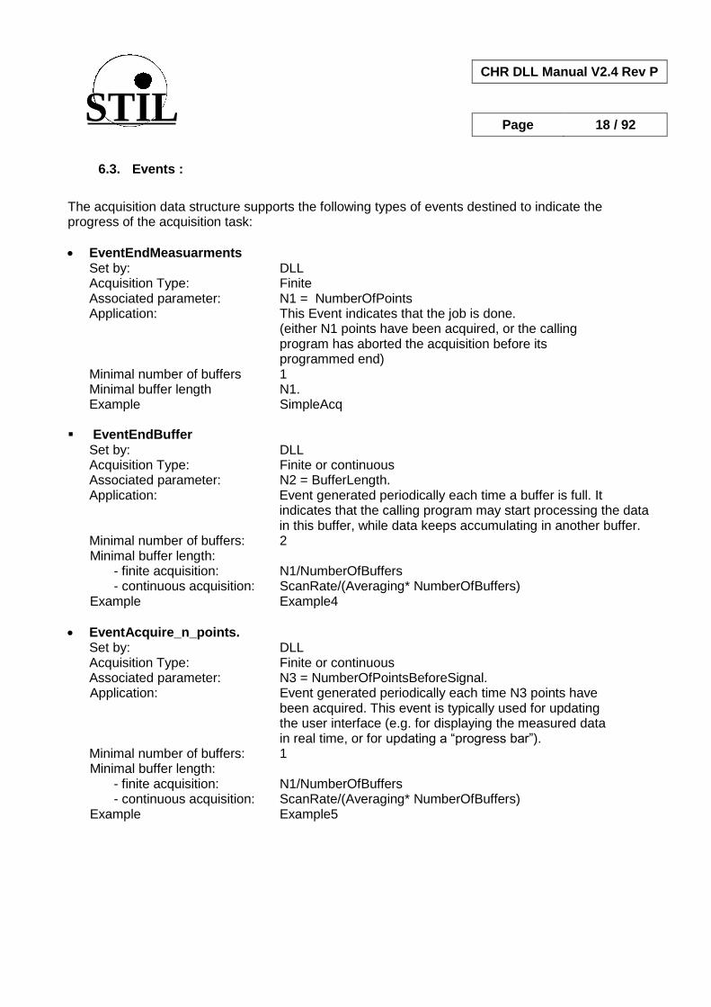
The acquisition data structure supports the following types of events destined to indicate the progress of the acquisition task:
EventEndMeasuarments Set by: DLL Acquisition Type: Finite Associated parameter: N1 = NumberOfPoints Application: This Event indicates that the job is done. (either N1 points have been acquired, or the calling program has aborted the acquisition before its programmed end)
Minimal number of buffers 1 Minimal buffer length N1. Example SimpleAcq EventEndBuffer Set by: DLL
Acquisition Type: Finite or continuous Associated parameter: N2 = BufferLength. Application: Event generated periodically each time a buffer is full. It indicates that the calling program may start processing the data
in this buffer, while data keeps accumulating in another buffer. Minimal number of buffers: 2 Minimal buffer length: - finite acquisition: N1/NumberOfBuffers - continuous acquisition: ScanRate/(Averaging* NumberOfBuffers) Example Example4
EventAcquire_n_points. Set by: DLL
Acquisition Type: Finite or continuous Associated parameter: N3 = NumberOfPointsBeforeSignal. Application: Event generated periodically each time N3 points have been acquired. This event is typically used for updating the user interface (e.g. for displaying the measured data in real time, or for updating a “progress bar”). Minimal number of buffers: 1 Minimal buffer length: - finite acquisition: N1/NumberOfBuffers - continuous acquisition: ScanRate/(Averaging* NumberOfBuffers) Example Example5
STIL
CHR DLL Manual V2.4 Rev P
Page 19 / 92
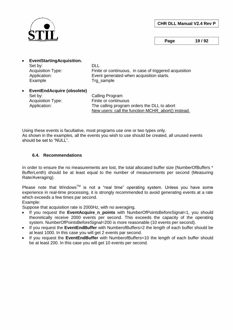
EventStartingAcquisition. Set by: DLL
Acquisition Type: Finite or continuous, in case of triggered acquisition Application: Event generated when acquisition starts. Example Trg_sample
EventEndAcquire (obsolete) Set by: Calling Program
Acquisition Type: Finite or continuous Application: The calling program orders the DLL to abort New users: call the function MCHR_abort() instead. Using these events is facultative, most programs use one or two types only. As shown in the examples, all the events you wish to use should be created, all unused events should be set to “NULL”.
6.4. Recommendations
In order to ensure the no measurements are lost, the total allocated buffer size (NumberOfBuffers * BufferLenth) should be at least equal to the number of measurements per second (Measuring Rate/Averaging). Please note that WindowsTM is not a “real time” operating system. Unless you have some experience in real-time processing, it is strongly recommended to avoid generating events at a rate which exceeds a few times par second. Example: Suppose that acquisition rate is 2000Hz, with no averaging.
If you request the EventAcquire_n_points with NumberOfPointsBeforeSignal=1, you should theoretically receive 2000 events per second. This exceeds the capacity of the operating system. NumberOfPointsBeforeSignal=200 is more reasonable (10 events per second).
If you request the EventEndBuffer with NumberofBuffers=2 the length of each buffer should be at least 1000. In this case you will get 2 events par second.
If you request the EventEndBuffer with NumberofBuffers=10 the length of each buffer should be at least 200. In this case you will get 10 events per second.
STIL
CHR DLL Manual V2.4 Rev P
Page 20 / 92
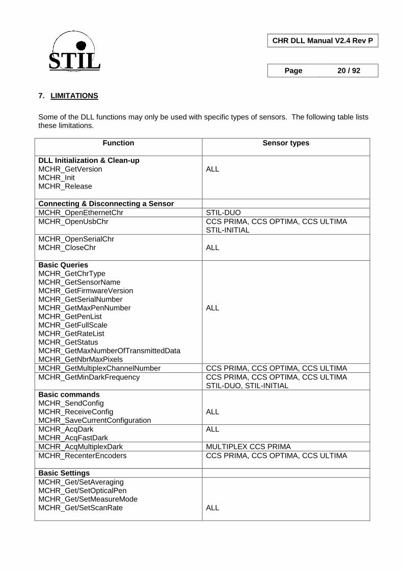
7. LIMITATIONS
Some of the DLL functions may only be used with specific types of sensors. The following table lists these limitations.
Function Sensor types
DLL Initialization & Clean-up MCHR_GetVersion MCHR_Init MCHR_Release
ALL
Connecting & Disconnecting a Sensor
MCHR_OpenEthernetChr STIL-DUO
MCHR_OpenUsbChr CCS PRIMA, CCS OPTIMA, CCS ULTIMA STIL-INITIAL
MCHR_OpenSerialChr MCHR_CloseChr
ALL
Basic Queries MCHR_GetChrType MCHR_GetSensorName MCHR_GetFirmwareVersion MCHR_GetSerialNumber MCHR_GetMaxPenNumber MCHR_GetPenList MCHR_GetFullScale MCHR_GetRateList MCHR_GetStatus MCHR_GetMaxNumberOfTransmittedData MCHR_GetNbrMaxPixels
ALL
MCHR_GetMultiplexChannelNumber CCS PRIMA, CCS OPTIMA, CCS ULTIMA
MCHR_GetMinDarkFrequency
CCS PRIMA, CCS OPTIMA, CCS ULTIMA STIL-DUO, STIL-INITIAL
Basic commands MCHR_SendConfig MCHR_ReceiveConfig MCHR_SaveCurrentConfiguration
ALL
MCHR_AcqDark MCHR_AcqFastDark
ALL
MCHR_AcqMultiplexDark MULTIPLEX CCS PRIMA
MCHR_RecenterEncoders
CCS PRIMA, CCS OPTIMA, CCS ULTIMA
Basic Settings
MCHR_Get/SetAveraging MCHR_Get/SetOpticalPen MCHR_Get/SetMeasureMode MCHR_Get/SetScanRate
ALL
STIL
CHR DLL Manual V2.4 Rev P
Page 21 / 92
Function Sensor types
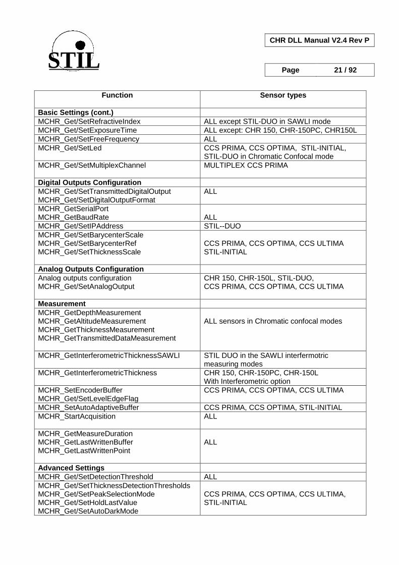
Basic Settings (cont.)
MCHR_Get/SetRefractiveIndex ALL except STIL-DUO in SAWLI mode
MCHR_Get/SetExposureTime ALL except: CHR 150, CHR-150PC, CHR150L
MCHR_Get/SetFreeFrequency ALL
MCHR_Get/SetLed
CCS PRIMA, CCS OPTIMA, STIL-INITIAL, STIL-DUO in Chromatic Confocal mode
MCHR_Get/SetMultiplexChannel
MULTIPLEX CCS PRIMA
Digital Outputs Configuration
MCHR_Get/SetTransmittedDigitalOutput MCHR_Get/SetDigitalOutputFormat
ALL
MCHR_GetSerialPort MCHR_GetBaudRate
ALL
MCHR_Get/SetIPAddress STIL--DUO
MCHR_Get/SetBarycenterScale MCHR_Get/SetBarycenterRef MCHR_Get/SetThicknessScale
CCS PRIMA, CCS OPTIMA, CCS ULTIMA STIL-INITIAL
Analog Outputs Configuration
Analog outputs configuration MCHR_Get/SetAnalogOutput
CHR 150, CHR-150L, STIL-DUO, CCS PRIMA, CCS OPTIMA, CCS ULTIMA
Measurement
MCHR_GetDepthMeasurement MCHR_GetAltitudeMeasurement MCHR_GetThicknessMeasurement MCHR_GetTransmittedDataMeasurement
ALL sensors in Chromatic confocal modes
MCHR_GetInterferometricThicknessSAWLI
STIL DUO in the SAWLI interfermotric measuring modes
MCHR_GetInterferometricThickness CHR 150, CHR-150PC, CHR-150L With Interferometric option
MCHR_SetEncoderBuffer MCHR_Get/SetLevelEdgeFlag
CCS PRIMA, CCS OPTIMA, CCS ULTIMA
MCHR_SetAutoAdaptiveBuffer CCS PRIMA, CCS OPTIMA, STIL-INITIAL
MCHR_StartAcquisition
ALL
MCHR_GetMeasureDuration MCHR_GetLastWrittenBuffer MCHR_GetLastWrittenPoint
ALL
Advanced Settings
MCHR_Get/SetDetectionThreshold ALL
MCHR_Get/SetThicknessDetectionThresholds MCHR_Get/SetPeakSelectionMode MCHR_Get/SetHoldLastValue MCHR_Get/SetAutoDarkMode
CCS PRIMA, CCS OPTIMA, CCS ULTIMA, STIL-INITIAL

STIL
CHR DLL Manual V2.4 Rev P
Page 22 / 92
Function Sensor types
Advanced Settings (cont.)
MCHR_Get/SetAutoModeThreshold MCHR_Get/SetAutoLedMode
CCS PRIMA, CCS OPTIMA, STIL-INITIAL
MCHR_Get/SetDoubleFrequencyParameters CCS PRIMA, STIL-INITIAL
CHR Interferometric mode functions MCHR_Get/SetBracketedMode MCHR_Get/SetLeftDetectionLimit MCHR_Get/SetRightDetectionLimit MCHR_Get/SetQualityThreshold
CHR 150, CHR-150PC, CHR-150L With Interferometric option
STIL-DUO Interferometric mode functions MCHR_GetSAWLINumberOfLayers MCHR_SetSAWLINumberOfLayers MCHR_GetSAWLIMinThickness MCHR_SetSAWLIMinThickness MCHR_GetSAWLIMaxThickness MCHR_SetSAWLIMaxThickness
STIL DUO in the SAWLI interfermotric measuring modes
Miscellaneous functions MCHR_Abort MCHR_GetLastError MCHR_GetErrorDescription MCHR_SendCommand MCHR_ReadSignal
ALL
Maintenance
MCHR_GetMeasurementForCalibration CHR 150, CHR-150PC, CHR-150L
MCHR_SendCalibration MCHR_SendFirmware
ALL
STIL
CHR DLL Manual V2.4 Rev P
Page 23 / 92
8. DLL INITIALIZATION AND CLEAN-UP FUNCTIONS
8.1. Initializing the DLL (MCHR_Init)
Syntax: WORD MCHR_Init(void) Description: This function initializes the DLL and allocates required memory
Arguments: None Return Value: Positive in case of success, MCHR_ERROR (=0) otherwise Example: See the "OnInitDLL" function in the "SampleCHRDlg.cpp" module of the "SampleCHR" sample program.
8.2. Releasing the DLL (MCHR_Release)
Syntax: WORD MCHR_Release (void) Description: This function closes the DLL and frees the memory allocated by MCHR_Init Arguments: None Positive in case of success, MCHR_ERROR (=0) otherwise. In order to know the origin of the error, call MCHR_GetLastError. Specific errors are: MCHR_ERROR_DLL_NOT_ACTIVE: the DLL has not been initialized. Example: See the "OnReleaseDLL" function in the "SampleCHRDlg.cpp" module of the "SampleCHR" sample program.

STIL
CHR DLL Manual V2.4 Rev P
Page 24 / 92
8.3. Getting the DLL version number (MCHR_GetVersion)
Syntax short MCHR_GetVersion(char *VersionNumber, short LengthBuffer) Description: This function returns the DLL version number. Arguments: VersionNumber: pointer to a character buffer LengthBuffer: length of the character buffer Return Value: Positive in case of success, MCHR_ERROR (=0) otherwise. In order to know the origin of the error, call MCHR_GetLastError. Specific errors are: MCHR_ERROR_DLL_NOT_ACTIVE: the DLL has not been initialized. Example: See the "OnInitDialog" function in the "SampleCHRDlg.cpp" module of the "SampleCHR" sample program.
STIL
CHR DLL Manual V2.4 Rev P
Page 25 / 92
9. CONNECTING AND DISCONNECTING A SENSOR
The following functions are used to connect the PC to a sensor. Sensors with two digital ports (e.g. RS232 and USB) may have both ports open simultaneously.
9.1. Connecting a sensor to a serial port (MCHR_OpenSerialChr)
Syntax: MCHR_ID_OpenSerialChr( LPCSTR SensorName, enChrType SensorType, WORD IdSerialPort, DWORD BuadRate, LPCSTR ConfigFile) Description: This function connects a sensor to an available serial port (RS232 or RS422) and adds it to the Sensor List Arguments: SensorName: a name that will be attributed to the sensor SensorType: should be one of the following values: MCHR_150, MCHR_CCS_PRIMA, MCHR_CCS_OPTIMA, MCHR_CCS_ULTIMA,
MCHR_DUO, MCHR_CCS_INITIAL (note: for CHR-150PC and CHR-150L sensors, select the type MCHR_150) IdSerialPort: the COM PORT ID of the Serial port to which the sensor is connected.
If the specified value is 0, the function searches the first COM PORT where a sensor is connected.
BaudRate: Serial port Baud rate. If the specified value is 0, the function searches automatically for the Baud rate
ConfigFile: The name of a file comprising the default configuration for the sensor. If null, the current sensor configuration is read.
Return Value: Positive in case of success, MCHR_ERROR (=0) otherwise. In order to know the origin of the error, call MCHR_GetLastError. In addition to general errors listed in §5.3, specific errors are: MCHR_ERROR_NOT_CONNECTED: no sensor was found on the specified COM Port
MCHR_ERROR_NAME_ALREADY_EXISTS: a sensor with the specified name exists already in the Sensor List.
MCHR_ERROR_ADD_SENSOR : an error occurred while adding the sensor to the Sensor List
MCHR_ERROR_SERIAL_PORT: an error occurred while attempting to initialize the COM port
Example: See the "OnOpenSerialCHR" function in the "SampleCHRDlg.cpp" module of the "SampleCHR" sample program.
STIL
CHR DLL Manual V2.4 Rev P
Page 26 / 92
9.2. Connecting a sensor to a serial port – obsolete (MCHR_OpenChr)
The MCHR_OpenChr(), obsolete function identical to MCHR_OpenSerialChr(), is maintained for compatibility with previous versions of the DLL.
9.3. Connecting a sensor to an Ethernet port (MCHR_OpenEthernetChr)
Syntax: MCHR_ID MCHR_OpenEthernetChr (LPCSTR SensorName, enChrType SensorType, char *IpAddress, CALLBACK_STATUS_CONNECTION CallBackFct, LPCSTR ConfigFile); Description: This function connects a sensor to an available Ethernet port and adds it to the Sensor List Arguments: SensorName: a name that will be attributed to the sensor SensorType: should be: MCHR_DUO IpAddress: IP address of the Ethernet port CallBackFct: optional Call back function ConfigFile: The name of a file comprising the default configuration for the sensor. If null, the
current sensor configuration is read. Return Value: Positive in case of success, MCHR_ERROR (=0) otherwise. In order to know the origin of the error, call MCHR_GetLastError. In addition to general errors listed in §5.3, specific errors are: MCHR_ERROR_NOT_CONNECTED: no sensor was found on the specified IP Address MCHR_ERROR_ADD_SENSOR: an error occurred while trying to add the sensor to the List:
MCHR_ERROR_NAME_ALREADY_EXISTS: a sensor with the specified name exists already in the Sensor List.
MCHR_ERROR_IP_ADDRESS: Impossible to connect to the specified address
9.4. Connecting a sensor to a USB port (MCHR_OpenUsbChr)
Syntax: MCHR_ID MCHR_OpenUsbChr(LPCSTR SensorName, enChrType SensorType, LPCSTR DeviceName, CALLBACK_STATUS_CONNECTION CallBackFct, LPCSTR ConfigFile) Description: This function connects a sensor to an available USB port and adds it to the Sensor List Arguments: SensorName: a name that will be attributed to the sensor SensorType: should be one of the following values:
MCHR_CCS_PRIMA, MCHR_CCS_OPTIMA. MCHR_CCS_ULTIMA

STIL
CHR DLL Manual V2.4 Rev P
Page 27 / 92
DeviceName: USB device name.
This parameter is necessary in order to manage several sensors (up to 4) connected to different USB ports simultaneously. It may be obtained by calling the function MCHR_GetUsbDeviceList() (cf. “Basic Queries” bellow).
If you only need to manage a single sensor on an USB port, set this parameter to NULL or to “”(empty string): in this case the DLL connects to the first available “CCS”-type USB device.
CallBack Fct: Optional call back function ConfigFile: The name of a file comprising the default configuration for the sensor. If null, the
current sensor configuration is read. Return Value: Positive in case of success, MCHR_ERROR (=0) otherwise. In order to know the origin of the error, call MCHR_GetLastError. In addition to general errors listed in §5.3, specific errors are: MCHR_ERROR_NOT_CONNECTED: the automatic search of a sensor on a free USB PORT
has failed MCHR_ERROR_ADD_SENSOR: an error occurred while trying to add the sensor to the Sensor
List: communication problem with the sensor MCHR_ERROR_NAME_ALREADY_EXISTS: a sensor with the specified name exists already
in the Sensor List. Example: See Example 8 and many other examples in the Samples\CCS_PRIMA folder.
9.5. Disconnecting a sensor (MCHR_CloseChr)
Syntax: short MCHR_CloseCHR(MCHR_ID SensorID) Description: This function disconnects the sensor and removes it from the Sensor List. Arguments: SensorID: sensor Identifier Return Value: positive in case of success, MCHR_ERROR (=0) otherwise. In order to know the origin of the error, call MCHR_GetLastError. Example: See the "OnCloseSensor" function in the "SampleCHRDlg.cpp" module of the "SampleCHR" sample program.
STIL
CHR DLL Manual V2.4 Rev P
Page 28 / 92
10. BASIC QUERIES
The following functions provide general information on a connected sensor. The information may be related to the specific sensor (e.g. the serial number) or common to all sensors of a given sensor type (e.g. rate list). All these functions exist in query mode only.
10.1. Getting the type of a connected sensor (MCHR_GetChrType)
Syntax: short MCHR_GetChrType (MCHR_ID SensorID, enChrType *ChrType) Description: This function returns the type of an open sensor.
Arguments: SensorID: Sensor Identifier ChrType: pointer to sensor type. Returned values may be MCHR_150, MCHR_CCS_PRIMA,
MCHR_CCS_OPTIMA or MCHR_CCS_ULTIMA, MCHR_DUO, MCHR_CCS_INITIAL Return value Positive in case of success, MCHR_ERROR (=0) otherwise. In order to know the origin of the error, call MCHR_GetLastError. Example: See the «OnGetChrType () » function of the "SampleCHRDlg.cpp" module in the "SampleCHR" sample program.
10.2. Getting the name of a connected sensor (MCHR_GetSensorName)
Syntax: short MCHR_GetSensorName(MCHR_ID SensorID, PCHAR pName); Description: This function gets the name attributed to the specified sensor.
Arguments: SensorID: the Sensor Identifier pName: a pointer to the sensor name Return value positive in case of success, MCHR_ERROR (=0) otherwise. In order to know the origin of the error, call MCHR_GetLastError. Example: See the "UpdateSensorInfo()" function of the "SampleCHRDlg.cpp" module in the "SampleCHR" sample program.

STIL
CHR DLL Manual V2.4 Rev P
Page 29 / 92
10.3. Getting the state of a connected sensor (MCHR_GetStatus)
Syntax: short MCHR_GetStatus(MCHR_ID SensorID) Description: This function returns the current state of the SENSOR. Please note that this state should not be confused with the State data item available on some sensors models.
Arguments: SensorID: the Sensor Identifier.
Return value In case of success the function returns the current sensor state, otherwise it returns
MCHR_ERROR (=0). The status may have one of the following values: MCHR_STATUS_NOT_INITIALIZED MCHR_STATUS_INITIALIZED, MCHR_STATUS_INIT_FAILED, MCHR_STATUS_WAIT_COMMAND, MCHR_STATUS_COMMAND_IN_PROGRESS, MCHR_STATUS_ACQUISITION_IN_PROGRESS, MCHR_STATUS_CONTINUOUS_ACQ_IN_PROGRESS,
MCHR_STATUS_STOP_ACQ_IN_PROGRESS Example: See the "OnAcqStop()" function of the "SampleCHRDlg.cpp" module in the "SampleCHR" sample program.
10.4. Getting the lowest authorized rate for the sensor (MCHR_GetMinDarkFrequency)
Syntax: short MCHR_ GetMinDarkFrequency (MCHR_ID SensorID, WORD *pScanRate) Description: This function returns minimal authorized frequency of the sensor. This frequency is determined by the Dark acquisition operation (if the dark signal is too high, low rates are not authorized). Arguments: SensorID: the Sensor Identifier. pScanRate: the min authorized rate, in Hz
Return value In case of success the function returns the current sensor state, otherwise it returns MCHR_ERROR (=0). In order to know the origin of the error, call MCHR_GetLastError.

STIL
CHR DLL Manual V2.4 Rev P
Page 30 / 92
10.5. Getting the firmware version number (MCHR_GetFirmwareVersion)
Syntax short MCHR_GetFirmwareVersion(MCHR_ID SensorID , char *VersionNumber, short LengthBuffer) Description: This function returns the version number of the sensor software Arguments: SensorID: Sensor Identifier VersionNumber: pointer to a character buffer LengthBuffer: length of the character buffer Return value Positive in case of success, MCHR_ERROR (=0) otherwise. In order to know the origin of the error, call MCHR_GetLastError. Example: See the "UpdateSensorInfo" function in the "SampleCHRDlg.cpp" module of the "SampleCHR"sample program.
10.6. Getting the serial number (MCHR_GetSerialNumber)
Syntax short MCHR_GetSerialNumber(MCHR_ID SensorID, char *SerialNumber, short LengthBuffer) Description: This function returns the serial number of the CHR. Arguments: SensorID: Sensor Identifier SerialNumber: pointer to a character buffer LengthBuffer: length of the character buffer Return Value: positive in case of success, MCHR_ERROR (=0) otherwise. In order to know the origin of the error, call MCHR_GetLastError. Example: See the "UpdateSensorInfo" function in the "SampleCHRDlg.cpp" module of the "SampleCHR"sample program.
10.7. Getting the list of “CCS” type USB devices (MCHR_GetUsbDeviceList)
Syntax: MCHR_ID MCHR_GetUsbDeviceList (char* UsbDeviceNameList[MCHR_MAX_SENSOR], short *DeviceNumber)
STIL
CHR DLL Manual V2.4 Rev P
Page 31 / 92
Description: This function returns the names of all available “CCS”-type USB devices, and indicates for each device if it has already been added to the sensor list or not. Arguments: UsbDeviceNameList: array of pointers to charcter strings for holding the returned devices
names. The array size (number of pointers) is MCHR_MAX_SENSOR, The size of each character string is MCHR_USB_DEVICE_NAME_LENGTH. Note: returned device names are preceded with a “*” character for devices that have already been connected.
DeviceNumber: The number of “CCS”-type USB devices found. Return Value: Positive in case of success, MCHR_ERROR (=0) otherwise. In order to know the origin of the error, call MCHR_GetLastError. Example: // Declarations short DeviceNumber = 0; char * UsbDeviceNameList [MCHR_MAX_SENSOR]; for (int j = 0; j < MCHR_MAX_SENSOR; j++) { UsbDeviceNameList[j] = new char [MCHR_USB_DEVICE_NAME_LENGTH]; } // function call
MCHR_GetUsbDeviceList (UsbDeviceNameList, &DeviceNumber); // Display the list of “CCS” USB devices (this step is optional) for (int i = 0; i < DeviceNumber; i++) { printf ("Device n°%d : %s", i+1, UsbDeviceNameList[i]); }
10.8. Getting the list of pre-set rates (MCHR_GetRateList)
Syntax: int *MCHR_GetRateList(MCHR_ID SensorID, WORD *RateListLength) Description: This function returns the list of pre-set frequencies (rates) of the specified sensor. The list depends on the sensor type. Arguments: SensorID: Sensor Identifier RateListLength : a pointer to the number of rates Return value: In case of success, the function returns a pointer to the list of pre-set rates. otherwise it returns NULL.

STIL
CHR DLL Manual V2.4 Rev P
Page 32 / 92
Example: See the «OnOpenSensor () » and « OnSelectSensor () » functions of the "SampleCHRDlg.cpp" module in the "SampleCHR" sample program.
10.9. Getting the measuring range of the current optical pen (MCHR_GetFullScale )
Syntax: short MCHR_GetFullScale (MCHR_ID SensorID, PWORD pFullScale); Description : Get the measuring range of the currently selected pen Arguments : SensorID : Sensor Identifier pFullScale: a pointer to the measuring range (value given in microns) Return value positive in case of success, MCHR_ERROR (=0) otherwise. In order to know the origin of the error, call MCHR_GetLastError. Example: See the «OnGetFullScale () » function of the "SampleCHRDlg.cpp" module in the "SampleCHR" sample program.
10.10. Getting the max number of optical pens for a sensor (MCHR_GetMaxPenNumber)
Syntax: short MCHR_GetMaxPenNumber(MCHR_ID SensorId); Description: This function gets the max number of the available optical pens for the specified sensor, in other words, the number of available calibration tables. This number depends on the sensor type.
Arguments: SensorID: the Sensor Identifier Return value: The number of calibration tables for the specified type of sensor. Example: See the "OnGetPenList()" function of the "SampleCHRDlg.cpp" module in the "SampleCHR" sample program.
STIL
CHR DLL Manual V2.4 Rev P
Page 33 / 92
10.11. Getting the list of the optical pens defined for a sensor (MCHR_GetPenList)
Syntax: short MCHR_GetPenList(MCHR_ID SensorID, PWORD pFullScale); Description: This function gets the list of the available optical pens for the specified sensor, in other terms the list of the calibration tables. Before calling this function it is recommended to call MCHR_GetMaxPenNumber() which returns the number of available calibration tables for the specified type of sensor, in order to correctly initialize the second argument.
Arguments: SensorID: the Sensor Identifier pFullScale: a pointer to a table of the measuring ranges of all pens (the value 999 =
MCHR_NO_PEN signifies calibration table that is not configured.) The size of the table is given by MCHR_GetMaxPenNumber().
Return value positive in case of success, MCHR_ERROR (=0) otherwise. Example: See the "OnGetPenList()" function of the "SampleCHRDlg.cpp" module in the "SampleCHR" sample program.
10.12. Getting the number of data items (MCHR_GetMaxNumberof TransmittedData)
Syntax: short MCHR_GetMaxNumberOfTransmittedData (MCHR_ID SensorID, WORD *MaxDataNumber) Description: This function returns the number of available data items, which depends on controller type. This information is necessary for MCHR_GetTransmittedDigitalOutput(). Arguments: SensorID: the Sensor Identifier MaxDataNumber: the number of available data items Return value positive in case of success, MCHR_ERROR (=0) otherwise. Example: See Example8 in the Samples\CCS_PRIMA folder. See also the "On MCHR_GetMaxNumberof TransmittedData()" function of the "SampleCHRDlg.cpp" module in the "SampleCHR" sample program.

STIL
CHR DLL Manual V2.4 Rev P
Page 34 / 92
10.13. Getting the number of photodetector pixels (MCHR_GetNbMaxPixels)
Syntax: short MCHR_ GetNbMaxPixels (MCHR_ID SensorID, int *pPixelsNumber) Description: This function returns the number of pixels of the sensor internal photodetector. This information is necessary for defining the buffer length for MCHR_ReadSignal() Arguments: SensorID: the Sensor Identifier pPixelNumber: the number pixels Return value positive in case of success, MCHR_ERROR (=0) otherwise.
10.14. Getting the number of channels (MCHR_GetMultiplexChannelNumber)
Syntax: short MCHR_ GetMultiplexChannelNumber (MCHR_ID SensorID, WORD *piChannelNumber) Description: This function returns the number of channels of a CCS PRIMA, OPTIMA or ULTIMA controller. Arguments: SensorID: the Sensor Identifier piChannel: pointer to the number of channels 4 for a CCS Prima4, 2 for CCS Prima2, 1 for all other CCS controllers. Return value positive in case of success, MCHR_ERROR (=0) otherwise.
STIL
CHR DLL Manual V2.4 Rev P
Page 35 / 92
11. BASIC COMMANDS
11.1. Setting, getting and saving the entire configuration
11.1.1. Setting the sensor configuration (MCHR_SendConfig)
Syntax: short MCHR_SendConfig(MCHR_ID SensorID, LPCSTR ConfigFile)
Description: This function sets the entire sensor configuration, using the parameters read in the specified configuration file Arguments: SensorID: Sensor Identifier ConfigFile:Name and path of the configuration file. Return value positive in case of success, MCHR_ERROR (=0) otherwise. In order to know the origin of the error, call MCHR_GetLastError. In addition to general errors listed in §5.3, specific errors are: MCHR_ERROR_READ_CONFIG_FILE : error reading the config file MCHR_ERROR_SEND_CONFIG_CHR: error while transmitting the configuration to the sensor Example: See the "OnSendConfig" function in the "SampleCHRDlg.cpp" module of the "SampleCHR" sample program.
11.1.2. Getting the sensor configuration (MCHR_ReceiveConfig)
Syntax: short MCHR_ReceiveConfig(MCHR_ID SensorID, LPCSTR ConfigFile)
Description: This function gets the entire current sensor configuration, and writes it to the specified configuration file. Arguments: SensorID: Sensor Identifier ConfigFile: Name and path of the configuration file. If NULL… Return value positive in case of success, MCHR_ERROR (=0) otherwise. In order to know the origin of the error, call MCHR_GetLastError.
STIL
CHR DLL Manual V2.4 Rev P
Page 36 / 92
In addition to general errors listed in §5.3, specific errors are: MCHR_ERROR_RECEIVE_CONFIG_CHR: error getting the sensor configuration MCHR_ERROR_WRITE_CONFIG_FILE: error while trying to write the configuration to the
specified file Example: See the "OnReceiveConfig" function in the "SampleCHRDlg.cpp" module of the "SampleCHR" sample program.
11.1.3. Saving the configuration to the non-volatile memory
(MCHR_SaveCurrentConfiguration)
Syntax : short MCHR_SaveCurrentConfiguration(MCHR_ID SensorID); Description : This function allows saving the current configuration to the sensor non-volatile memory, so that it is conserved when the sensor is powered off and on again. Arguments : SensorID: Sensor Identifier Return value positive in case of success, MCHR_ERROR (=0) otherwise. In order to know the origin of the error, call MCHR_GetLastError. Example : See the «OnSaveConfig () » function in the "SampleCHRDlg.cpp" module of the "SampleCHR" sample program.
11.2. Recording the Dark signal
11.2.1. Standard Dark signal acquisition (MCHR_AcqDark)
Syntax: short MCHR_AcqDark(MCHR_ID SensorID, enSCAN_RATE_LIST *pMinFreq); Description: This function updates the Dark signal of the sensor at all acquisition rates and informs on the minimum authorized acquisition rate. (If some rates are not authorized, see the sensor Operating and Maintenance Manual for methods for cleaning the fiber optics). The dark signals are saved in the sensor non-volatile memory. Note that the execution of this function may take a long time (of the order of one minute for some sensor types). No other commands should be sent to the sensor before processing of this command is done.
STIL
CHR DLL Manual V2.4 Rev P
Page 37 / 92
Arguments: SensorID: the Sensor Identifier pMinFreq: pointer to the minimal authorized rate; Return value positive in case of success, MCHR_ERROR (=0) otherwise. In order to know the origin of the error, call MCHR_GetLastError. Example: See the "OnSetDark()" function of the "SampleCHRDlg.cpp" module in the "SampleCHR" sample program.
11.2.2. Fast Dark signal acquisition (MCHR_AcqFastDark)
Syntax : short MCHR_AcqFastDark (MCHR_ID SensorID, WORD Average, float InfluenceValue);
Description : This function updates the Dark signal for the current acquisition rate only. The Dark signal is not saved to the sensor non-volatile memory.
Arguments : SensorID : Sensor Identifier Average: an integer indicating the number of successive Dark-signal acquisition to be averaged.
If set to 0, the default value is used (50) InfluenceValue: Ponderation (in percent) of the new acquisition in the new calculated Dark
signal: new Dark = { InfluenceValue*Acquired Dark + (100-InfluenceValue)*Previous Dark} / 100 The default value is 100.
Return value positive in case of success, MCHR_ERROR (=0) otherwise. In order to know the origin of the error, call MCHR_GetLastError. In addition to general errors listed in §5.3, specific errors are: MCHR_ERROR_DARK_NOT_VALID: Dark acquisition failed
Example : See the «OnAcqFastDark () » function in « SampleCHRDlg .cpp» in the « SampleCHR » sample program.
11.2.3. Dark for multiplexed sensor (MCHR_AcqMultiplexDark)
Syntax : short MCHR_AcqMultiplexDark (MCHR_ID SensorID, int*pMinFreq, Word wNbElem);
Description : This function acquires and saves the Dark signal for all channels of a multiplexed CCS controller (in contrast with the MCHR_AcqDark which acquires ans saves the Dark for the current channel only).
STIL
CHR DLL Manual V2.4 Rev P
Page 38 / 92
Arguments : SensorID : Sensor Identifier pMinFreq : a pointer to an array for receiving the min athorized rate of all the channels wNbElem: the number of elements of the array (call MCHR_GetMultiplexChannelNumber() to get the correct value of wNbElem)
Return value positive in case of success, MCHR_ERROR (=0) otherwise. In order to know the origin of the error, call MCHR_GetLastError. The function returns un error if called for single-channel sensors.
11.3. Recentering the encoders
The following function allows recentering the encoders; more precisely, it sets the encoder value to 1030 /2 at the current encoder position (this function is usually called when the scanning system is at the origin position of the translation stage/s).
11.3.1. Recentering the encoders (MCHR_RecenterEncoders)
Syntax : short MCHR_RecenterEncoders(MCHR_ID SensorID, bool Encoder1, bool Encoder2, bool Encoder3);
Description : This function allows centering the selected encoders (CCS sensors only). Arguments : SensorID: Sensor Identifier Encoder1: true to recenter encoder 1, false otherwise. Encoder2: true to recenter encoder 2, false otherwise. Encoder3: true to recenter encoder 3, false otherwise. Return value positive in case of success, MCHR_ERROR (=0) otherwise. In order to know the origin of the error, call MCHR_GetLastError. Example : See EncoderSamples.cpp in the Samples\CCS_PRIMA\Encoder Sample file folder.

STIL
CHR DLL Manual V2.4 Rev P
Page 39 / 92
12. BASIC SETTINGS
The following functions allow getting and setting the basic parameters of a connected sensor. Note that these functions modify the parameters in the volatile memory: in order to save the modified parameters to the non-volatile memory, the MCHR_SaveCurrentConfiguration should be called.
12.1. Measuring mode
All sensor types feature at least 2 measuring modes (Chromatic Confocal Distance and Thickness). CHR 150 sensors may have a third optional measuring mode (Interferometric). STIL-DUO sensors have 4 modes.
12.1.1. Getting the measuring mode (MCHR_GetMeasureMode)
Syntax: short MCHR_GetMeasureMode(MCHR_ID SensorID, enMeasureMode *pMode); Description: This function selects the measuring mode of the sensor (Distance or Thickness). Arguments: SensorID: the Sensor Identifier pMode : pointer to the measuring mode of the sensor. Return value positive in case of success, MCHR_ERROR (=0) otherwise. In order to know the origin of the error, call MCHR_GetLastError. Example: See the "OnGetMeasureMode()" function of the "SampleCHRDlg.cpp" module in the "SampleCHR" sample program.
12.1.2. Setting the measuring mode (MCHR_SetMeasureMode)
Syntax: short MCHR_SetMeasureMode(MCHR_ID SensorID, enMeasureMode Mode); Description: This function selects the measuring mode of the sensor
Measuring Mode code
Distance (Chromatic Confocal 1 surface) 0
Thickness (Confocal Confocal 2 surfaces) 1
Thickness (Spectral Interferometric mode) 2
Distance (Spectral Interferometric) 3

STIL
CHR DLL Manual V2.4 Rev P
Page 40 / 92
Arguments: SensorID: the Sensor Identifier Mode : Measuring mode of the sensor: Return value positive in case of success, MCHR_ERROR (=0) otherwise. In order to know the origin of the error, call MCHR_GetLastError. In addition to general errors listed in §5.3, specific errors are: MCHR_ERROR_INTERFEROMETRIC_MODE_NOT_AUTORIZED: Impossible to set the
sensor to Interferometric mode, since this option is not authorized. Example: See the "OnSetMeasureMode()" function of the "SampleCHRDlg.cpp" module in the "SampleCHR" sample program.
12.2. Sampling Rate
There exist 2 approaches for setting the sampling rate: - using a list of pre-set rates. You may use the MCHR_GetRateList function to get the value (in Hz) of each of the pre-set rates of the sensor. - specifying an exposure time in Hz.
12.2.1. Getting the pre-set rate (MCHR_GetScanRate)
Syntax: short MCHR_GetScanRate (MCHR_ID SensorID, WORD *pScanRate); Description: This function gets the current acquisition rate identifier (see MCHRType.h for a list of values for each sensor type).
Arguments: SensorID: the Sensor Identifier ScanRate: value of the desired acquisition rate. Return value positive in case of success, MCHR_ERROR (=0) otherwise. In order to know the origin of the error, call MCHR_GetLastError. Example: See the "OnGetScanRate()" function of the "SampleCHRDlg.cpp" module in the "SampleCHR" sample program.
12.2.2. Setting the pre-set rate (MCHR_SetScanRate)
Syntax: short MCHR_SetScanRate (MCHR_ID SensorID, WORD ScanRate)
STIL
CHR DLL Manual V2.4 Rev P
Page 41 / 92
Description: This function sets the acquisition rate identifier.
Arguments: SensorID: the Sensor Identifier ScanRate: value of the desired acquisition rate id. (See sensor manual or MCHRType.h for a list of rate id for each controller type).
Return value positive in case of success, MCHR_ERROR (=0) otherwise. In order to know the origin of the error, call MCHR_GetLastError. In addition to general errors listed in §5.3, specific errors are: MCHR_ERROR_SCANRATE_TOO_HIGH: the rate is too high for transmitting all data items currently configured Example: See the "OnSetScanRate()" function of the "SampleCHRDlg.cpp" module in the "SampleCHR" sample program.
12.2.3. Getting the free rate (MCHR_GetScanRate)
Syntax: short MCHR_GetFreeFrequency (MCHR_ID SensorID, int *pFrequency); Description: This function gets the current acquisition rate Arguments: SensorID: the Sensor Identifier pFrequency: value of the acquisition rate, in Hz Return value positive in case of success, MCHR_ERROR (=0) otherwise. In order to know the origin of the error, call MCHR_GetLastError.
12.2.4. Setting the free rate (MCHR_SetFreeRate)
Syntax: short MCHR_SetScanRate (MCHR_ID SensorID, int iFrequency) Description: This function sets the acquisition rate.
Arguments: SensorID: the Sensor Identifier iFrequency: value of the desired acquisition rate, in Hz
Return value positive in case of success, MCHR_ERROR (=0) otherwise. In order to know the origin of the error, call MCHR_GetLastError.

STIL
CHR DLL Manual V2.4 Rev P
Page 42 / 92
12.2.5. Getting the exposure time (MCHR_GetExposureTime)
Syntax: short MCHR_GetExposureTime(MCHR_ID SensorID, PWORD ExposureTime); Description: This function gets the current exposure time (in microseconds) Arguments: SensorID: the Sensor Identifier Exposure time: a pointer to the exposure time, in microseconds. Return value positive in case of success, MCHR_ERROR (=0) otherwise. In order to know the origin of the error, call MCHR_GetLastError. Example: See the "OnGetExposureTime()" function of the "SampleCHRDlg.cpp" module in the "SampleCHR" sample program.
12.2.6. Setting the exposure time (MCHR_SetExposureTime)
Syntax: short MCHR_SetExposureTime(MCHR_ID SensorID, WORD ExposureTime); Description: This function provides an alternative way for setting acquisition rate for STI-DUO, STIL-INITIAL and CCS sensors. Arguments: SensorID: the Sensor Identifier ExposureTime : Exposure time, in microseconds (See the sensor Operating and Maintenance
manual for the range of authorized values for the specified type of sensor). Example: See the "OnSetExposureTime()" function of the "SampleCHRDlg.cpp" module in the "SampleCHR" sample program.
12.3. Averaging
When the sensor is configured to an averaging n ≥ 1, A single value is transmitted for each n acquired points. (Output data rate= sampling rate /n).
12.3.1. Getting the averaging factor (MCHR_GetAveraging)
Syntax: short MCHR_GetAveraging( MCHR_ID SensorID, PWORD pAveragingValue);
STIL
CHR DLL Manual V2.4 Rev P
Page 43 / 92
Description: This function gets the averaging factor.
Arguments: SensorID: the Sensor Identifier AveragingValue : a pointer to the averaging factor . Return value positive in case of success, MCHR_ERROR (=0) otherwise. In order to know the origin of the error, call MCHR_GetLastError. Example: See the "OnGetAveraging()" function of the "SampleCHRDlg.cpp" module in the "SampleCHR" sample program.
12.3.2. Setting the averaging factor (MCHR_SetAveraging)
Syntax: short MCHR_SetAveraging(MCHR_ID SensorID, WORD AveragingValue); Description: This function sets the averaging factor.
Arguments: SensorID: the Sensor Identifier AveragingValue : Averaging factor (between 1 and 999). Return value positive in case of success, MCHR_ERROR (=0) otherwise. In order to know the origin of the error, call MCHR_GetLastError. Example: See the "OnSetAveraging()" function of the "SampleCHRDlg.cpp" module in the "SampleCHR" sample program.
12.4. Optical pen selection
Selecting the active optical pen means selecting the id (number) of the calibration table memorized in the sensor controller. The max number of authorized calibration tables depends on the sensor type. It may be found using the MCHR_GetMaxPenNumber() function. The list of existing calibration tables may be found using the MCHR_GetPenList() function. Some sensors have several optical pen (channels) connected permanently, one of which is active. For selecting the active channel, please refer to §12.7 ”channel selection”.
12.4.1. Getting the active optical pen (MCHR_GetOpticalPen)
Syntax: short MCHR_GetOpticalPen( MCHR_ID SensorID, PWORD pOpticalPen,
PDWORD pFullScale);

STIL
CHR DLL Manual V2.4 Rev P
Page 44 / 92
Description: This function gets the optical pen number and the measuring range of the selected pen.
Arguments: SensorID: the Sensor Identifier pOpticalPen : a pointer to the identifier of the calibration table selected pFullScale: a pointer to the measuring range (value given in microns) a pen number of MCHR_NO_PEN (999) or a measuring range of 65535 indicate the no pen is currently selected. Return value positive in case of success, MCHR_ERROR (=0) otherwise. In order to know the origin of the error, call MCHR_GetLastError. Example: See the "OnGetOpticalPen()" function of the "SampleCHRDlg.cpp" module in the "SampleCHR" sample program.
12.4.2. Setting the active optical pen (MCHR_SetOpticalPen)
Syntax: short MCHR_SetOpticalPen( MCHR_ID SensorID, WORD OpticalPen,
PDWORD pFullScale); Description: This function selects the optical pen, in other terms, it selects the number of the calibration table in the sensor. It returns the measuring range of the selected pen in the last argument.
Arguments: SensorID: the Sensor Identifier OpticalPen : identifier of the calibration table selected (the range of authorized values depends
on controller type). pFullScale: a pointer to the measuring range (value given in microns) Return value positive in case of success, MCHR_ERROR (=0) otherwise. In order to know the origin of the error, call MCHR_GetLastError. Example: See the "OnSetOpticalPen()" function of the "SampleCHRDlg.cpp" module in the "SampleCHR" sample program.
STIL
CHR DLL Manual V2.4 Rev P
Page 45 / 92
12.5. Refractive index (MCHR_GetRefractiveIndex)
The sample refractive index is required in the Thickness measuring mode. For STIL-DUO in interferometric (SAWLI) mode, please use MCHR_SetSpectralRefractivesIndexes Instead of MCHR_GetRefractiveIndex.
12.5.1. Getting the refractive index (MCHR_GetRefractiveIndex)
Syntax: short MCHR_GetRefractiveIndex(MCHR_ID SensorID, float * pRefractiveIndexValue); Description: This function gets the sample refractive index.
Arguments: SensorID: the Sensor Identifier pRefractiveIndexValue : pointer to the refractive index of the sample Return value positive in case of success, MCHR_ERROR (=0) otherwise. In order to know the origin of the error, call MCHR_GetLastError. Example: See the "OnAcqEpaisseur()" function of the "SampleCHRDlg.cpp" module in the "SampleCHR" sample program.
12.5.2. Setting the refractive index (MCHR_SetRefractiveIndex)
Syntax: short MCHR_SetRefractiveIndex(MCHR_ID SensorID, float RefractiveIndexValue); Description: This function sets the sample refractive index. This parameter is required for measuring in thickness mode.
Arguments: SensorID: the Sensor Identifier RefractiveIndexValue : refractive index of the sample (e.g. 1.512). should be equal or greater
than 1. Return value positive in case of success, MCHR_ERROR (=0) otherwise. In order to know the origin of the error, call MCHR_GetLastError. Example: See the "OnSetRefractiveIndex()" function of the "SampleCHRDlg.cpp" module in the "SampleCHR" sample program.

STIL
CHR DLL Manual V2.4 Rev P
Page 46 / 92
12.6. LED Brightness
For some sensor models with internal LED light source, LED brightness may be set by command.
12.6.1. Getting the LED brightness (MCHR_GetLed)
Syntax: short MCHR_GetLed(MCHR_ID SensorID, int * pLed); Description: This function gets the LED brightness level.
Arguments: SensorID: the Sensor Identifier pLed : pointer to the LED brightness level (0-100) Return value positive in case of success, MCHR_ERROR (=0) otherwise. In order to know the origin of the error, call MCHR_GetLastError. Examples: See the "OnGetLed()" function of the "SampleCHRDlg.cpp" module in the "SampleCHR" sample program. See also Example8 in the Samples\CCS_Prima folder.
12.6.2. Setting the LED brightness (MCHR_SetLed)
Syntax: short MCHR_SetLed(MCHR_ID SensorID, int Led); Description: This function sets the LED brightness level.
Arguments: SensorID: the Sensor Identifier Led : desired LED brightness level (0-100) Return value positive in case of success, MCHR_ERROR (=0) otherwise. In order to know the origin of the error, call MCHR_GetLastError. Example: See the "OnSetLed()" function of the "SampleCHRDlg.cpp" module in the "SampleCHR" sample program. See also Example8 in the Samples\CCS_Prima folder

STIL
CHR DLL Manual V2.4 Rev P
Page 47 / 92
12.7. Channel selection
For multiplexed sensors several optical pens are connected permanently, and one of them is active. The following functions allow setting/requesting the selected channel
12.7.1. Getting the selected channel (MCHR_GetMultiplexChannel)
Syntax: short MCHR_GetMultiplexChannel(MCHR_ID SensorID, WORD * piChannel); Description: This function gets the id of the currently selected channel for Multiplex CCS. Note: for 1-channel CCS, this function returns un error. Use MCHR_GetMultiplexChannelNumber() To get the number of channels before calling this function.
Arguments: SensorID: the Sensor Identifier piChannel : pointer to the selected channel (1-4) Return value positive in case of success, MCHR_ERROR (=0) otherwise. In order to know the origin of the error, call MCHR_GetLastError.
12.7.2. Setting the selected channel (MCHR_SetMultiplexChannel)
Syntax: short MCHR_SetMultiplexChannel(MCHR_ID SensorID, WORD iChannel); Description: This function sets the active channel of a multiplex CCS. Note: for 1-channel CCS, this function returns un error. Use MCHR_GetMultiplexChannelNumber() To get the number of channels before calling this function.
Arguments: SensorID: the Sensor Identifier iChannel : desired channel (1-4) Return value positive in case of success, MCHR_ERROR (=0) otherwise. In order to know the origin of the error, call MCHR_GetLastError.
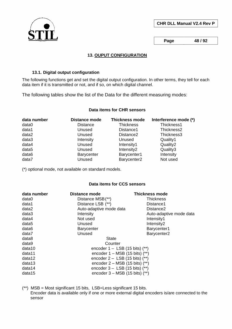
STIL
CHR DLL Manual V2.4 Rev P
Page 48 / 92
13. OUPUT CONFIGURATION
13.1. Digital output configuration
The following functions get and set the digital output configuration. In other terms, they tell for each data item if it is transmitted or not, and if so, on which digital channel.
The following tables show the list of the Data for the different measuring modes:
Data items for CHR sensors
data number Distance mode Thickness mode Interference mode (*) data0 Distance Thickness Thickness1 data1 Unused Distance1 Thickness2 data2 Unused Distance2 Thickness3 data3 Intensity Unused Quality1 data4 Unused Intensity1 Quality2 data5 Unused Intensity2 Quality3 data6 Barycenter Barycenter1 Intensity data7 Unused Barycenter2 Not used (*) optional mode, not available on standard models.
Data items for CCS sensors
data number Distance mode Thickness mode data0 Distance MSB (**) Thickness data1 Distance LSB (**) Distance1 data2 Auto-adaptive mode data Distance2 data3 Intensity Auto-adaptive mode data data4 Not used Intensity1 data5 Unused Intensity2 data6 Barycenter Barycenter1 data7 Unused Barycenter2 data8 State data9 Counter data10 encoder 1 – LSB (15 bits) (**) data11 encoder 1 – MSB (15 bits) (**) data12 encoder 2 – LSB (15 bits) (**) data13 encoder 2 – MSB (15 bits) (**) data14 encoder 3 – LSB (15 bits) (**) data15 encoder 3 – MSB (15 bits) (**) (**) MSB = Most significant 15 bits, LSB=Less significant 15 bits.
Encoder data is available only if one or more external digital encoders is/are connected to the sensor

STIL
CHR DLL Manual V2.4 Rev P
Page 49 / 92
Data items for STIL-INITIAL sensors
data number Distance mode Thickness mode data0 Distance MSB (**) Thickness data1 Distance LSB (**) Distance1 data2 Auto-adaptive mode data Distance2 data3 Intensity Auto-adaptive mode data data4 Unused Intensity1 data5 Unused Intensity2 data6 Barycenter Barycenter1 data7 Unused Barycenter2 data8 State data9 Counter data10 Unused data11 Unused data12 Unused data13 Unused data14 Unused data15 Unused (**) MSB = Most significant 15 bits, LSB=Less significant 15 bits.
Data items for STIL-DUO sensors in Chromatic Confocal modes
data number CCI Distance mode CCI Thickness mode data0 Distance MSB (**) Thickness data1 Distance LSB (**) Distance1 data2 Unused Distance2 data3 Intensity Counter data4 Unused Intensity1 data5 Counter Intensity2 data6 Barycenter Barycenter1 data7 Unused Barycenter2 data8 Unused data9 State data10 Unused data11 Unused data12 Unused data13 Unused data14 Unused data15 Unused
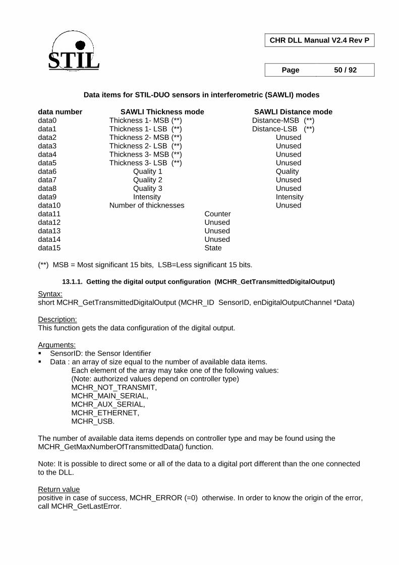
STIL
CHR DLL Manual V2.4 Rev P
Page 50 / 92
Data items for STIL-DUO sensors in interferometric (SAWLI) modes
data number SAWLI Thickness mode SAWLI Distance mode data0 Thickness 1- MSB (**) Distance-MSB (**) data1 Thickness 1- LSB (**) Distance-LSB (**) data2 Thickness 2- MSB (**) Unused data3 Thickness 2- LSB (**) Unused data4 Thickness 3- MSB (**) Unused data5 Thickness 3- LSB (**) Unused data6 Quality 1 Quality data7 Quality 2 Unused data8 Quality 3 Unused data9 Intensity Intensity data10 Number of thicknesses Unused data11 Counter data12 Unused data13 Unused data14 Unused data15 State (**) MSB = Most significant 15 bits, LSB=Less significant 15 bits.
13.1.1. Getting the digital output configuration (MCHR_GetTransmittedDigitalOutput)
Syntax: short MCHR_GetTransmittedDigitalOutput (MCHR_ID SensorID, enDigitalOutputChannel *Data) Description: This function gets the data configuration of the digital output. Arguments: SensorID: the Sensor Identifier Data : an array of size equal to the number of available data items.
Each element of the array may take one of the following values: (Note: authorized values depend on controller type) MCHR_NOT_TRANSMIT,
MCHR_MAIN_SERIAL, MCHR_AUX_SERIAL, MCHR_ETHERNET, MCHR_USB. The number of available data items depends on controller type and may be found using the MCHR_GetMaxNumberOfTransmittedData() function. Note: It is possible to direct some or all of the data to a digital port different than the one connected to the DLL. Return value positive in case of success, MCHR_ERROR (=0) otherwise. In order to know the origin of the error, call MCHR_GetLastError.

STIL
CHR DLL Manual V2.4 Rev P
Page 51 / 92
Example: See the "On MCHR_GetMaxNumberof TransmittedData()" function of the "SampleCHRDlg.cpp" module in the "SampleCHR" sample program.
13.1.2. Getting the digital output configuration – obsolete (MCHR_GetDigitalOutput)
This is an obsolete function maintained for compatibility with previous versions of the DLL. It should not be used for CCS sensors. It is replaced by MCHR_GetTransmittedDigitalOutput().
13.1.3. Setting the digital output configuration (MCHR_SetTransmittedDigitalOutput)
Syntax: short MCHR_SetTransmittedDigitalOutput (MCHR_ID SensorID, enDigitalOutputChannel *Data) Description: This function tells for each data item if it is transmitted or not, and if so – on which digital channel. Notes:
(1) Digital output configuration is carried out automatically by all the “comprehensive” data acquisition functions. The MCHR_SetTransmittedDigitalOutput() function is needed only in case the “rapid” acquisition function (MCHR_GetTransmittedDataMeasurement) is used.
(2) In some cases (STIL DUO in spectral interferometric mode, STIL DUO and CCS Prima in
Chromatic Confocal Distance mode) distance or thickness data may be measured with 30-bit resolution and transmitted using two 15-bit “data items” called “Distance MSB” and “Distance LSB” (“Most Significant Bits” and “Less Significant Bits”, respectively). In these cases: - to get 30 bit digital resolution both data items should be selected and directed to the
same digital port. - to get 15 bit resolution, the MSB should be directed to the selected channel and the LSB
data should be set to MCHR_NOT_TRANSMIT (3) It is possible to direct some or all of the data to a digital port which is different from the one
connected to the CHR.
Arguments: SensorID: the Sensor Identifier Data : an array of size equal to the number of available data items.
Each element of the array may take one of the following values: MCHR_NOT_TRANSMIT,
MCHR_MAIN_SERIAL, MCHR_AUX_SERIAL, MCHR_ETHERNET, MCHR_USB.
(Note: authorized values depend on controller type)

STIL
CHR DLL Manual V2.4 Rev P
Page 52 / 92
The number of available data items depends on controller type and may be found using the MCHR_GetMaxNumberOfTransmittedData() function. Return value positive in case of success, MCHR_ERROR (=0) otherwise. In order to know the origin of the error, call MCHR_GetLastError. In addition to general errors listed in §5.3, specific errors are: MCHR_ERROR_SCANRATE_TOO_HIGH: the current measuring rate is too high for
transmitting the specified data items on the serial link. Example: See Example 8 in the Samples\CCS_PRIMA folder. See also the "On SetTransmittedDigitalOutput ()" function of the "SampleCHRDlg.cpp" module in the "SampleCHR" sample program.
13.1.4. Setting the digital output configuration – obsolete (MCHR_SetDigitalOutput)
Note: This is an obsolete function maintained for compatibility with previous versions of the DLL. It should not be used for CCS sensors. It is replaced by MCHR_SetTransmittedDigitalOutput().
13.2. Output data format
Digital data format may be MCHR_ASCII or MCHR_BINARY. For some sensor types a third format exists: MCHR_PACKET.
13.2.1. Getting the digital output format (MCHR_GetDigitalOutputFormat)
Syntax: short MCHR_GetDigitalOutputFormat( MCHR_ID SensorID,
enDigitalOutputFormat *pFormat); Description: This function gets the digital output current format.
Arguments: SensorID: the Sensor Identifier pFormat : a pointer to the format of the transmitted data. Most sensors have ASCII and binary
formats, some have the additional packet mode. Return value positive in case of success, MCHR_ERROR (=0) otherwise. In order to know the origin of the error, call MCHR_GetLastError.

STIL
CHR DLL Manual V2.4 Rev P
Page 53 / 92
Example: See the "OnGetOutputFormat()" function of the "SampleCHRDlg.cpp" module in the "SampleCHR" sample program.
13.2.2. Setting the digital output format (MCHR_SetDigitalOutputFormat)
Syntax: short MCHR_SetDigitalOutputFormat(MCHR_ID SensorID, enDigitalOutputFormat Format); Description: This function selects the digital output format. Arguments: SensorID: the Sensor Identifier Format : format of the transmitted data. Formats are defined in the "MCHRtype.h" module. Most
sensors have ASCII and binary formats, some have the additional packet mode. Return value positive in case of success, MCHR_ERROR (=0) otherwise. In order to know the origin of the error, call MCHR_GetLastError. Example: See the "OnSetOutputFormat()" function of the "SampleCHRDlg.cpp" module in the "SampleCHR" sample program.
13.3. Output data encoding
For some sensor types it is possible to modify the way barycentre data and “thickness” measuring- mode data items are encoded as 15-bit integer values.
13.3.1. Getting the thickness scale (MCHR_GetThicknessScale)
Syntax: short MCHR_GetThicknessScale (MCHR_ID SensorID, float *pValue) Description: This function gets the scale for the Thickness, Distance1 and Distance2 data items in Distance mode (CCS sensors only ). Arguments: SensorID: the Sensor Identifier pValue: thickness scale. The digital output value of the above data items is given by: Output value= 7FFF * Physical value [in microns] / (Thickness Scale * Measuring Range) Return value positive in case of success, MCHR_ERROR (=0) otherwise. In order to know the origin of the error, call MCHR_GetLastError.

STIL
CHR DLL Manual V2.4 Rev P
Page 54 / 92
Example: See the "OnGetThicknessScale()" function of the "SampleCHRDlg.cpp" module in the "SampleCHR" sample program.
13.3.2. Setting the thickness scale (MCHR_SetThicknessScale)
Syntax: short MCHR_SetThicknessScale (MCHR_ID SensorID, float Value) Description: This function determines the scale for the Thickness, Distance1 and Distance2 data items in Distance mode (CCS sensors only ). Arguments: SensorID: the Sensor Identifier Value: thickness scale. The digital output value of the above data items is given by: Output value= 7FFF * Physical value [in microns] / (Thickness Scale * Measuring Range) Return value positive in case of success, MCHR_ERROR (=0) otherwise. In order to know the origin of the error, call MCHR_GetLastError. Example: See the "OnSetThicknessScale()" function of the "SampleCHRDlg.cpp" module in the "SampleCHR" sample program.
13.3.3. Getting the barycenter scale (MCHR_GetBarycenterScale)
Syntax: short MCHR_GetBarycenterScale (MCHR_ID SensorID, float *pValue) Description: This function determines the scale for the digital output of the Barycenter data item in both Distance mode and Thickness mode (CCS sensors only ). Arguments: SensorID: the Sensor Identifier pValue: the barycenter scale value. The digital output value for the Barycenter data item
Is given by: output value = (barycenter [in pixels] – barycenter offset)*barycenter scale. Note: The Barycenter offset can be obtained using the MCHR_GetBarycenterOffset
Return value positive in case of success, MCHR_ERROR (=0) otherwise. In order to know the origin of the error, call MCHR_GetLastError. Example: See the "OnGetBarycenterScale()" function of the "SampleCHRDlg.cpp" module in the "SampleCHR" sample program.

STIL
CHR DLL Manual V2.4 Rev P
Page 55 / 92
13.3.4. Setting the barycenter scale (MCHR_SetBarycenterScale)
Syntax: short MCHR_SetBarycenterScale (MCHR_ID SensorID, float Value) Description: This function determines the scale for the digital output of the Barycenter data item in both Distance mode and Thickness mode (CCS sensors only ). Arguments: SensorID: the Sensor Identifier Value: the barycenter scale value. The digital output value for the Barycenter data item
Is given by: ( output value = barycenter [in pixels] – barycenter offset)*barycenter scale. Notes:
(1) The Barycenter offset is determined using the MCHR_SetBarycenterOffset (2) The values of the barycenter offset and barycenter scale satisfy the relation:
(Index of last used pixel – barycenter offset)* barycenter scale <= 7FFF Return value positive in case of success, MCHR_ERROR (=0) otherwise. In order to know the origin of the error, call MCHR_GetLastError. Example: See the "OnSetBarycenterScale()" function of the "SampleCHRDlg.cpp" module in the "SampleCHR" sample program.
13.3.5. Getting the barycenter offset (MCHR_GetBarycenterRef)
Syntax: short MCHR_GetBarycenterRef (MCHR_ID SensorID, float *pValue) Description: This function determines the offset for the digital output of the Barycenter data item in both Distance mode and Thickness mode (CCS sensors only ). Arguments: SensorID: the Sensor Identifier pValue: the barycenter offset value. The digital output value for the Barycenter data item
Is given by: ( output value = barycenter [in pixels] – barycenter offset)*barycenter scale. Note: The Barycenter scale is determined using the MCHR_SetBarycenterOffset
Return value positive in case of success, MCHR_ERROR (=0) otherwise. In order to know the origin of the error, call MCHR_GetLastError. Example: See the "OnGetBarycenterRef()" function of the "SampleCHRDlg.cpp" module in the "SampleCHR" sample program.
STIL
CHR DLL Manual V2.4 Rev P
Page 56 / 92
13.3.6. Setting the barycenter offset (MCHR_SetBarycenterRef)
Syntax: short MCHR_SetBarycenterRef (MCHR_ID SensorID, float Value) Description: This function determines the offset for the digital output of the Barycenter data item in both Distance mode and Thickness mode (CCS sensors only ). Arguments: SensorID: the Sensor Identifier Value: the barycenter offset value. The digital output value for the Barycenter data item
Is given by: ( output value = barycenter [in pixels] – barycenter offset)*barycenter scale. Notes:
(3) The Barycenter scale is determined using the MCHR_SetBarycenterScale (4) The values of the barycenter offset and barycenter scale satisfy the relation:
(Index of last used pixel – barycenter offset)* barycenter scale <= 7FFF Return value positive in case of success, MCHR_ERROR (=0) otherwise. In order to know the origin of the error, call MCHR_GetLastError. Example: See the "OnSetBarycenterRef()" function of the "SampleCHRDlg.cpp" module in the "SampleCHR" sample program.
13.4. RS232/RS422 channel configuration
The following function may be used after connecting the sensor with the “automatic search” option in order to get the baud rate and the identifier of the COM port connected to the sensor.
13.4.1. Getting the COM Port Identifier of a connected sensor (MCHR_GetSerialPort)
Syntax: short MCHR_GetSerialPort(MCHR_ID SensorID) Description: This function gets the identifier of the PC COM PORT connected to the sensor.
Arguments: SensorID: the sensor Identifier Return value In case of success the function returns the PORT COM identifier, otherwise it returns MCHR_ERROR (=0) otherwise. In order to know the origin of the error, call MCHR_GetLastError.

STIL
CHR DLL Manual V2.4 Rev P
Page 57 / 92
Example: See the "UpdateSensorInfo()" function of the "SampleCHRDlg.cpp" module in the "SampleCHR" sample program.
13.4.2. Getting the Baud rate of a connected sensor (MCHR_GetBaudRate)
Syntax: long MCHR_GetBaudRate(MCHR_ID SensorID); Description: This function gets the current Baud rate of the serial port connected to the specified sensor.
Arguments: SensorID: the CHR Identifier Return value In case of success the function returns the Baud rate; Otherwise it returns MCHR_ERROR (=0) . In order to know the origin of the error, call MCHR_GetLastError. Example: See the "UpdateSensorInfo()" function of the "SampleCHRDlg.cpp" module in the "SampleCHR" sample program.
13.5. Ethernet channel configuration
It is possible to use the RS232/RS422 link in order to set the IP address for the Ehternet link.
13.5.1. Getting the sensor IP address (MCHR_GetIPAddress)
Syntax : short MCHR_GetIPAddress (MCHR_ID SensorID, char *Address) Description : Get the sensor IP Address for Ethernet connection (this may be sent by serial link before opening connection to the port) Arguments : SensorID: Sensor Identifier Address: IP Address Return value positive in case of success, MCHR_ERROR (=0) otherwise. In order to know the origin of the error, call MCHR_GetLastError. Example : See the «OnGetIPAddress () » function in the « SampleCHRDlg .cpp» file of the « SampleCHR » sample program.

STIL
CHR DLL Manual V2.4 Rev P
Page 58 / 92
13.5.2. Setting the sensor IP address (MCHR_SetIPAddress)
Syntax : short MCHR_SetIPAddress (MCHR_ID SensorID, char *Address) Description : Set the sensor IP Address for Ethernet connection Arguments : SensorID: Sensor Identifier Address: IP Address Return value positive in case of success, MCHR_ERROR (=0) otherwise. In order to know the origin of the error, call MCHR_GetLastError. In addition to general errors listed in §5.3, specific errors are: MCHR_ERROR_IP_ADDRESS : the IP address specified is not valid Example : See the «OnSetIPAddress () » function in the « SampleCHRDlg .cpp» file of the « SampleCHR » sample program.
13.6. Analog output configuration
The following table lists the data items that may be transmitted to the analog outputs. Note that some items that can be transmitted by the digital outputs cannot be directed to the digital outputs (e.g. Counter, State, Encoder data). Note that the same data may be directed at the same time to a digital output and to an analog output. data item code Distance mode Thickness mode Interference mode 0 Distance Thickness Thickness1 1 Not used Distance1 Thickness2 2 Not used Distance2 Thickness3 3 Intensity Not used Quality1 4 Not used Intensity1 Quality2 5 Not used Intensity2 Quality3
13.6.1. Getting the analog output configuration (MCHR_GetAnalogOutput)
Syntax: short MCHR_GetAnalogOutput(
MCHR_ID SensorID, WORD AnaID, PWORD pData,
PWORD pZeroValue, PWORD pMaxValue);

STIL
CHR DLL Manual V2.4 Rev P
Page 59 / 92
Description: This function gets the configuration of one analog output Arguments: SensorID: the Sensor Identifier AnaID : identifier of the analog output selected (0 or 1) pData: a pointer to the number of the data attributed to the analog output (0 to 7). pZeroValue: a pointer to the value in measuring scale of the data for which the output is 0 V. pMaxValue: a pointer to the value in measuring scale of the data for which the output is 10 V. Return value positive in case of success, MCHR_ERROR (=0) otherwise. In order to know the origin of the error, call MCHR_GetLastError. Example: See the "OnGetAnaChannel()" function of the "SampleCHRDlg.cpp" module in the "SampleCHR" sample program.
13.6.2. Setting the analog output configuration (MCHR_SetAnalogOutput)
Syntax: short MCHR_SetAnalogOutput(
MCHR_ID SensorID, WORD AnaID, WORD Data,
WORD ZeroValue, WORD MaxValue);
Description: This function attributes a data item to one of the Analog outputs and sets data values corresponding to 0 V and 10 V output. Arguments: SensorID: the Sensor Identifier AnaID : identifier of the analog output selected (0 or 1) Data: code of the data to be attributed to the analog output (0 to 7). ZeroValue: value in measuring scale of the specified data for which the output will be 0 V. MaxValue: value in measuring scale of the specified data for which the output will be 10 V. Return value positive in case of success, MCHR_ERROR (=0) otherwise. In order to know the origin of the error, call MCHR_GetLastError. Example: See the "OnSetAnaChannel()" function of the "SampleCHRDlg.cpp" module in the "SampleCHR" sample program.
STIL
CHR DLL Manual V2.4 Rev P
Page 60 / 92
14. MEASUREMENT
The following functions are used for launching and controlling measurements, for getting the measured data, and for getting information on a measurement which is currently in progress.
14.1. « Comprehensive » measurement functions
The “comprehensive” measurement functions accomplish the following tasks: - Configure the sensor to the desired measuring range - Configure the digital output so as to transmit the desired data items - Set the buffers for collecting the desired data items - Start the acquisition thread Note: In case you wish encoder data and/or “auto-adaptive” data to be transmitted as well, call the “MCHR_SetEncoderBuffers” and/or the MCHR_SetAutoAdaptiveBuffer functions before calling the “comprehensive” acquisition function.
14.1.1. Measurement in Distance/Depth mode (MCHR_GetDepthMeasurement)
Syntax: MCHR_GetDepthMeasurement( MCHR_ID SensorID, tyAcqParam Parameters,
PFLOAT *pArrayDepth, PFLOAT *pArrayIntensity, PFLOAT *pArrayCounter, PFLOAT *pArrayBarycenter, PFLOAT *pArrayStatus)
Description: This function allows acquiring the data measured by the sensor in distance mode. The Z axis points downwards, in other words, the z-coordinate ("depth") increases when the sample point gets further from the optical pen tip. In this mode, some the sensor models deliver 5 data per measured points (Depth, Intensity, Counter, Barycenter position, State). For other models sensor models, counter and State data are not available. Before starting the acquisition, this function configures the sensor to the Distance measuring mode and directs the selected data (i.e. data for which the array pointer argument in the function call is not NULL ) to the digital output specified when opening the sensor.
Warning: This function should not be used for measuring Barycenter data for sensor calibration. Arguments: SensorID : The Sensor Identifier Parameters: a structure of measurement parameters (See §6)

STIL
CHR DLL Manual V2.4 Rev P
Page 61 / 92
pArrayDepth: an array of pointers to distance data buffers. If NULL, distance data is not acquired. (distance is in "Depth" mode, in other words, the Z axis points downwards).
pArrayIntensity: an array of pointers to intensity data buffers. If NULL, intensity data is not acquired.
pArrayCounter: an array of pointers to the counter data buffers. If NULL, intensity data is not
acquired. (Note: For some sensor models counter data is not available, please consult the User Manual)
pArrayBarycenter: an array of pointers to Barycenter data buffers. If Null, Barycenter data is not
acquired. (Barycenter data is peak position on the photodetector. This data is used for sensor calibration only).
pArrayStatus: an array of pointers to the State data buffers. If NULL, State data is not acquired.
(Note: For some sensor models State data is not available, please consult the User Manual) Note: the use of several buffers for the same data enables real-time processing of the data, e.g. real time display, as shown in the example bellow. Return value positive in case of success, MCHR_ERROR (=0) otherwise. In order to know the origin of the error, call MCHR_GetLastError. In addition to general errors listed in §5.3, specific errors are:
MCHR_ERROR_TRIGGER_TYPE: the specified trigger mode does not exist MCHR_ERROR_START_RECEP_THREAD: an error occurred while attempting to start the
acquisition thread ERROR_CHR_BUFFER_FULL: the reception buffers are full, the data is not read rapidly
enough Examples: The “Example4” sample program shows the case of a Triggered continuous distance-mode acquisition using 4 buffers. A second example may be found in the "SampleCHRDlg.cpp" sample program: see the "OnAcqDistance" function in the "SampleCHRDlg", and the "ThreadAffichage()" function in the "DisplayGraph.cpp" module.
STIL
CHR DLL Manual V2.4 Rev P
Page 62 / 92
14.1.2. Measurement in Distance/Altitude mode (MCHR_GetAltitudeMeasurement)
Syntax: MCHR_GetAltitudeMeasurement( MCHR_ID SensorID, tyAcqParam Parameters,
PFLOAT *pArrayAltitude, PFLOAT *pArrayIntensity, PFLOAT *pArrayCounter, PFLOAT *pArrayBarycenter, PFLOAT *pArrayStatus)
Description: This function is almost identical to "GetDepthMeasurement. The only difference resides in the fact that Altitude is acquired instead of Depth (Altitude=Measuring range – Depth). In other terms, the Z axis points upwards and the Altitude data increases when the sample point gets closer to the optical pen tip. In this mode, some the sensor models deliver 5 data per measured points (Depth, Intensity, Counter, Barycenter position, State). For other models sensor models, counter and State data are not available. Before starting the acquisition, this function configures the sensor to the Distance measuring mode and directs the selected data (i.e. data for which the array pointer argument in the function call is not NULL ) to the digital output specified when opening the CHR. Note: This function should not be used for measuring Barycenter data for sensor calibration. Arguments: SensorID : The Sensor Identifier Parameters: a stucture of measurement parameters (See §6) pArrayAltitude: a pointer to distance data buffer. If NULL, distance data is not acquired.
(distance is in "Altitude" mode, in other words, the Z axis points upwards).
pArrayIntensity: a pointer to intensity data buffer. If NULL, intensity data is not acquired. pArrayCounter: an array of pointers to the counter data buffers. If NULL, intensity data is not
acquired. (Note: For some sensor models counter data is not available, please consult the User Manual)
pArrayBarycenter: an array of pointers to Barycenter data buffers. If Null, Barycenter data is not
acquired. (Barycenter data is peak position on the photodetector. This data is used for sensor calibration only).
pArrayStatus: an array of pointers to the State data buffers. If NULL, State data is not acquired.
(Note: For some sensor models State data is not available, please consult the User Manual)

STIL
CHR DLL Manual V2.4 Rev P
Page 63 / 92
Return value positive in case of success, MCHR_ERROR (=0) otherwise. In order to know the origin of the error, call MCHR_GetLastError. In addition to general errors listed in §5.3, specific errors are:
MCHR_ERROR_TRIGGER_TYPE: the specified trigger mode does not exist MCHR_ERROR_START_RECEP_THREAD: an error occurred while attempting to start the
acquisition thread ERROR_CHR_BUFFER_FULL: the reception buffers are full, the data is not read rapidly
enough Examples: The “Example5” sample program shows the case of a Triggered continuous acquisition using a single buffer. See also the « AltitudeAcqSample » sample program in the "AltitudeAcqSample.cpp » module.
14.1.3. Measurement in Thickness mode (MCHR_GetThicknessMeasurement)
Syntax: MCHR_GetThicknessMeasurement( MCHR_ID SensorID, tyAcqParam Parameters,
PFLOAT *pArrayThickness, PFLOAT *pArrayDistance1, PFLOAT *pArrayIntensity1, PFLOAT *pArrayBarycenter1, PFLOAT *pArrayDistance2, PFLOAT *pArrayIntensity2, PFLOAT *pArrayBarycenter2, PFLOAT *pArrayStatus PFLOAT *pArrayCounter)
Description: This function starts acquisition in Thickness mode. In this mode the sensor returns 7 data per measured sample point (Distance, Intensity and Barycenter for each surface and thickness). The Z axis is in Depth mode (pointing downwards). Before starting the acquisition, this function configures the sensor to the Thickness measuring mode and directs the selected data (i.e. data for which the array pointer argument in the function call is not NULL ) to the digital output specified when opening the CHR.
Arguments: SensorId: the Sensor Identifier Parameters: data structure for setting the measurement parameters (cf. §6) pArrayThickness: a pointer array to the Thickness data buffers pArrayDistance1: a pointer array to the Distance (depth) data buffers of the first surface pArrayIntensity1: a pointer array to the Intensity data buffers of the first surface pArrayBarycenter1: a pointer array to the Intensity data buffers of the first surface

STIL
CHR DLL Manual V2.4 Rev P
Page 64 / 92
pArrayDistance2: a pointer array to the Distance (depth) data buffers of the second surface pArrayIntensity2: a pointer array to the Intensity data buffers of the second surface pArrayBarycenter2: a pointer array to the Intensity data buffers of the second surface pArrayStatus: a pointer array to the State data buffer pArrayCounter: a pointer array to the Counter data buffer Notes: If any of the pointer arrays is NULL, the corresponding data is not acquired. For some sensor models the State and the Counter data are not available. Return value positive in case of success, MCHR_ERROR (=0) otherwise. In order to know the origin of the error, call MCHR_GetLastError. In addition to general errors listed in §5.3, specific errors are:
MCHR_ERROR_TRIGGER_TYPE: the specified trigger mode does not exist MCHR_ERROR_START_RECEP_THREAD: an error occurred while attempting to start the
acquisition thread ERROR_CHR_BUFFER_FULL: the reception buffers are full, the data is not read rapidly
enough Examples The “Example6” sample program shows the case of non-triggered continuous acquisition in thickness mode using 4 buffers.
Another example may be found in the "SampleCHR" program (see the "OnAcqEpaisseur()" function in the "SampleCHRDlg.cpp" module and the "ThreadAffichage()" function in the "Displaygraph.cpp" module).
14.1.4. Measurement in SAWLI mode (MCHR_GetInterferometricThicknessSAWLI )
This function is destined to STIL-DUO in the interferometric mode Syntax :
MCHR_ID MCHR_ GetInterferometricThicknessSAWLI ( MCHR_ID SensorID, tyAcqParam Parameters PFLOAT *pThickness1, PFLOAT *pThickness2, PFLOAT *pThickness3, PFLOAT *pQuality1, PFLOAT *pQuality2, PFLOAT *pQuality3, PFLOAT *pIntensity,
PFLOAT *NbThickness, PFLOAT *pCounter, PFLOAT *pState);
Description : Acquisition function for the Specral Interferometric (SAWLI) Thickness mode.

STIL
CHR DLL Manual V2.4 Rev P
Page 65 / 92
Note: in Distance mode set the number of layer to 1, and the refractive index to 1.0. The Distance Data may be comuted from the air gap thickness using the following raelation: Distance = 160µm – Thickness1. Arguments : SensorId: the Sensor Identifier Parameters: data structure for setting the measurement parameters (cf. §6) pThickness1: a pointer to the Thickness1 data buffers pThickness2: a pointer to the Thickness2 data buffers pThickness3: a pointer to the Thickness3 data buffers pQuality1: a pointer to the Quality1 data buffers pQuality2: a pointer to the Quality1 data buffers pQuality3: a pointer to the Quality1 data buffers pIntensity: a pointer to the Intensity data buffers pNbThickness: a pointer to the Number Of Thicknesses data Buffers pCounter : a pointer to the Counter data Buffers pState: a pointer to the State Data buffer.
Returned Value : positive in case of success, MCHR_ERROR (=0) otherwise. In order to know the origin of the error, call MCHR_GetLastError.
14.1.5. Measurement in CHR Interferometric mode (MCHR_GetInterferometricThickness )
This function is for CHR150 with the Interferometric option. Syntax :
MCHR_ID MCHR_ GetInterferometricThickness ( MCHR_ID SensorID, tyAcqParam Parameters PFLOAT *pArrayThickness1, PFLOAT *pArrayThickness2, PFLOAT *PArrayThickness3, PFLOAT *PArrayQuality1, PFLOAT *PArrayQuality2, PFLOAT *PArrayQuality3, PFLOAT *PArrayIntensity); Description : Acquisition function for the Interferometric mode. This mode is available only if the sensor was ordred with th"interferometric" mode. It necessitates a dedicated optical pen. Note that the maximum authorized rate is MCHR_300 Hz. Before starting the acquisition, this function configures the sensor to the Distance measuring mode and directs the selected data (i.e. data for which the array pointer argument in the function call is not NULL ) to the digital output specified when opening the CHR.
STIL
CHR DLL Manual V2.4 Rev P
Page 66 / 92
Arguments : SensorId: the Sensor Identifier Parameters: data structure for setting the measurement parameters (cf. §6) pArrayThickness1: a pointer array to the Thickness1 data buffers pArrayThickness2: a pointer array to the Thickness2 data buffers pArrayThickness3: a pointer array to the Thickness3 data buffers pArrayQuality1: a pointer array to the Quality1 data buffers pArrayQuality2: a pointer array to the Quality1 data buffers pArrayQuality3: a pointer array to the Quality1 data buffers pArrayIntensity: a pointer array to the Intensity data buffers
Returned Value : positive in case of success, MCHR_ERROR (=0) otherwise. In order to know the origin of the error, call MCHR_GetLastError. In addition to general errors listed in §5.3, specific errors are:
MCHR_ERROR_INTERFEROMETRIC_MODE_NOT_AUTHORIZED: the interferometric option is not active for the specified sensor
MCHR_ERROR_TRIGGER_TYPE: the specified trigger mode does not exist MCHR_ERROR_START_RECEP_THREAD: an error occurred while attempting to start the
acquisition thread ERROR_CHR_BUFFER_FULL: the reception buffers are full, the data is not read rapidly
enough
Examples The “Example7” sample program shows the case of triggered continuous interferometric-mode acquisition using 4 buffers with saturation test and indication of acquisition start upon trigger reception.
Another example can be found in the "OnAcqInterferometrique()" and the "Thread Affichage" functions in the "SampleCHRDlg.cpp" and "Displaygraph.cpp" modules, respectively, of the "SampleCHR" program.

STIL
CHR DLL Manual V2.4 Rev P
Page 67 / 92
14.2. Setting the buffers for complementary data
In case you wish encoder data and/or “auto-adaptive mode data” to be transmitted as well, use the following functions to set buffers for these data BEFORE calling one of the “comprehensive” measurement functions. These functions may not be used with the “rapid” measurement function MCHR_GetDataMeasurement. Please note that these encoder data and “auto-adaptive mode data” are available for some sensor types only.
14.2.1. Setting the buffers for encoder data (MCHR_SetEncoderBuffer)
Syntax : short MCHR_SetEncoderBuffer (MCHR_ID SensorID, PDWORD *pArrayEncoder1, PDWORD *pArrayEncoder2, PDWORD *pArrayEncoder3) Description : Set the buffers to collect encoder data This function should be called before any of the “comprehensive” measurement functions (cf. §14.1) in case one or more encoders are connected to the sensor (CCS sensors only). Arguments : SensorID: Sensor Identifier pArrayEncoder1 : address of buffer for encoder1 data pArrayEncoder2 : address of buffer for encoder1 data (NULL if not applicable) pArrayEncoder3 : address of buffer for encoder1 data (NULL if not applicable)
Return value positive in case of success, MCHR_ERROR (=0) otherwise. In order to know the origin of the error, call MCHR_GetLastError. Example : See the EncoderSample.cpp module of the Samples\CCS_PRIMA\Encoder Sample Files folder. See also the «OnSetEncoderBuffer () » function in the « SampleCHRDlg .cpp» file of the « SampleCHR » sample program.
14.2.2. Setting the buffer for the “auto adaptive mode” data (MCHR_SetAutoAdaptiveBuffer)
Syntax : short MCHR_SetAutoAdaptiveBuffer (MCHR_ID SensorID, PFLOAT *pArrayAutoAdaptive) Description : Set the buffer to collect auto-adaptive mode data This function should be called before any of the “comprehensive” measurement functions (cf. §14.1) in case Auto-adaptive Rate or Auto-adaptive LED mode are enabled. (CCS sensors only). Note: collecting this data is optional.
STIL
CHR DLL Manual V2.4 Rev P
Page 68 / 92
Arguments : SensorID: Sensor Identifier pArrayAutoAdaptive : address of buffer for collecting the auto-adaptive mode data Return value positive in case of success, MCHR_ERROR (=0) otherwise. In order to know the origin of the error, call MCHR_GetLastError. Example : See the EncoderSample.cpp module of the Samples\CCS_PRIMA\Encoder Sample Files folder. See also the «OnSetAutoAdaptiveBuffer () » function in the « SampleCHRDlg .cpp» file of the « SampleCHR » sample program.
14.3. Rapid measurement function
The rapid acquisition function sets the buffers for the desired data items and starts the acquisition thread. Before calling this function, The sensor should be configured to the desired measuring mode and the digital outputs should be correctly configured.
14.3.1. Launching a rapid measurement (MCHR_GetTransmittedDataMeasurement)
Syntax: MCHR_GetTransmittedDataMeasurement( MCHR_ID SensorID, tyAcqParam Parameters,
PFLOAT *pArrayData0, PFLOAT *pArrayData1, PFLOAT *pArrayData2, PFLOAT *pArrayData3, PFLOAT *pArrayData4, PFLOAT *pArrayData5, PFLOAT *pArrayData6, PFLOAT *pArrayData7 PFLOAT *pArrayData8, PFLOAT *pArrayData9, PFLOAT *pArrayData10, PFLOAT *pArrayData11, PFLOAT *pArrayData12, PFLOAT *pArrayData13, PFLOAT *pArrayData14, PFLOAT *pArrayData15)
Description: This function starts acquisition in the current acquisition mode. Data is collected under 2 conditions: - The data item has been previously selected by the MCHR_SetTransmittedDigitalData() function, - The corresponding pointer argument in the function call is not null.

STIL
CHR DLL Manual V2.4 Rev P
Page 69 / 92
Arguments: SensorId: the Sensor Identifier Parameters: data structure for setting the measurement parameters (cf. §6) pArrayData0 - pArrayData15: pointer arrays to the data item buffers
Please consult the MCHR_SetTransmittedDigitalData() function description for the definition of data items 0..15 for each measuring mode.
Notes: (1) The sensor should be configured to the correct measuring mode and the desired output data should be selected before this function is called. (2) If the sensor is in Distance mode, distance data is by default in the Depth mode (Z axis pointing downward). See example code 2 (§5.4.3) for transforming Depth data to Altitude data. Return value positive in case of success, MCHR_ERROR (=0) otherwise. In order to know the origin of the error, call MCHR_GetLastError. In addition to general errors listed in §5.3, specific errors are:
MCHR_ERROR_TRIGGER_TYPE: the specified trigger mode does not exist MCHR_ERROR_START_RECEP_THREAD: an error occurred while attempting to start the
acquisition thread ERROR_CHR_BUFFER_FULL: the reception buffers are full, the data is not read rapidly
enough Examples See Example8 in the Samples\CCS_PRIMA folder.
14.3.2. Launching a rapid measurement – obsolete (MCHR_GetDataMeasurement)
This is an obsolete function maintained for compatibility with previous versions of the DLL. It should not be used for CCS sensors.
14.4. Exiting trigger mode (MCHR_StartAcquisition)
If the “TriggerFlag” of the Acquisition parameter structure is set to “TRUE”, the acquisition function configures the sensor to the desired trigger modes. The MCHR_StartAcquisition function may be used to exit the trigger mode. In particular, this function may disarm the trigger if case the sensor has been configured to the “MCHR_TYPE_TRG” trigger mode but no trigger pulse has been received on the sensor “Sync In” TTL input. Syntax: short MCHR_StartAcquisition(MCHR_ID SensorID); Description: This function allows replacing a hardware TRIGGER signal when the sensor is in the MCHR_TYPE_TRG Triggered mode. Acquisition starts immediately after reception of this command.

STIL
CHR DLL Manual V2.4 Rev P
Page 70 / 92
Arguments: Sensor ID: Sensor Identifier Return value positive in case of success, MCHR_ERROR (=0) otherwise. In order to know the origin of the error, call MCHR_GetLastError. Example: See the "OnAcqStart" function of the "SampleCHRDlg.cpp" module of the "SampleCHR" sample program.
14.5. Active edge for trigger signals
The following functions allow getting and setting the active edge (or the active state) for the trigger signal. They are not requested when the “comprehensive” measuring functions are used but may be necessary BEFORE calling the ”Rapid” acquisition function MCHR_GetTransmittedDataMeasurement(). Authorized values are:
MCHR_FALLING_EDGE , MCHR_RISING_EDGE, MCHR_LOW_LEVEL, MCHR_HIGH_LEVEL.
14.5.1. Getting the active edge for trigger signals
Syntax: short MCHR_GetLevelEdgeFlag(MCHR_ID SensorID, enLevelEdgeFlag *Value); Description: This function gets the active edge (or active state) for trigger signals. Arguments: Sensor ID: Sensor Identifier Value: value of the active edge Return value positive in case of success, MCHR_ERROR (=0) otherwise. In order to know the origin of the error, call MCHR_GetLastError. Example: See the "OnGetActiveEdge" function of the "SampleCHRDlg.cpp" module of the "SampleCHR" sample program.
14.5.2. Setting the active edge for trigger signals
Syntax: short MCHR_SetLevelEdgeFlag(MCHR_ID SensorID, enLevelEdgeFlag Value); Description: This function sets the active edge (or active state) for trigger signals before calling the MCHR_GetTransmittedDataMeasurement() function.

STIL
CHR DLL Manual V2.4 Rev P
Page 71 / 92
Arguments: Sensor ID: Sensor Identifier Value: value of the active edge Return value positive in case of success, MCHR_ERROR (=0) otherwise. In order to know the origin of the error, call MCHR_GetLastError. Example: See the "OnSetActiveEdge" function of the "SampleCHRDlg.cpp" module of the "SampleCHR" sample program.
14.6. Controlling measurement
The following functions may be used for getting information on the duration and state of current measurement.
14.6.1. Getting the measurement duration (MCHR_GetMeasureDuration )
Syntax : short MCHR_GetMeasureDuration (MCHR_ID SensorID, double *Duration) Description : Returns the duration (in ms) of a series of measurements. Arguments : SensorID: Sensor Identifier Duration: Expected duration in milliseconds. Return value positive in case of success, MCHR_ERROR (=0) otherwise. In order to know the origin of the error, call MCHR_GetLastError. Example: See the «OnAcqEnd () » function of the "SampleCHRDlg.cpp" module in the "SampleCHR" sample program.
14.6.2. Getting the last buffer written to (MCHR_GetLastWrittenBuffer)
Syntax : short MCHR_GetLastWrittenBuffer (MCHR_ID SensorID, enAcqEventType EventType, int *BufferIndex, int *PointIndex); Description : This function informs on the identifier of the last buffer to which data was written during the acquisition in progress. It should be called after recepetion of the specified event. Arguments : SensorID: Sensor Identifier
STIL
CHR DLL Manual V2.4 Rev P
Page 72 / 92
EventType (see definition of enAcqEventType in “MCHRTYPE.h”) should be one of the following: MCHR_BUFFER_EVENT: corresponds to EventEndBuffer of the acquisition parameter structure MCHR_ONE_STEP_EVENT: corresponds to EventAcquire_n_Points of this structure, MCHR_END_MEASUREMENT: corresponds to EventEndMeasurement of this structure.
BufferIndex: a pointer to the Buffer identifier (if equals to –1, no acquisition is currently in progress).
PointIndex: a pointer to the index of the last point written. Return value positive in case of success, MCHR_ERROR (=0) otherwise. In order to know the origin of the error, call MCHR_GetLastError. Example: See the «ThreadAffichage () » function of the « DisplayGraph .cpp» module in the "SampleCHR" sample program.
14.6.3. Getting the last written point (MCHR_GetLastWrittenPoint)
Syntax : short MCHR_GetLastWrittenPoint (MCHR_ID SensorID, int *Index); Description : This function returns the index (number) of the last point written to the acquisition buffer. It may be called after reception of the event indicating that a pre-determined number of points have been acquired. (EventAcquire_n_Points). This function can only be used when the number of buffers is 1, otherwise the more general MCHR_GetLastWrittenBuffer() should be used. Arguments : SensorID : Sensor Identifier Index: returns the index of the last written point (if equals –1, no acquisition is currently in
progress). Return value positive in case of success, MCHR_ERROR (=0) otherwise. In order to know the origin of the error, call MCHR_GetLastError. Example: See the «ThreadAffichage () » function of the « DisplayGraph .cpp» module in the "SampleCHR" sample program. Return value positive in case of success, MCHR_ERROR (=0) otherwise. In order to know the origin of the error, call MCHR_GetLastError. Example: See the «ThreadAffichage () » function of the « DisplayGraph .cpp» module in the "SampleCHR" sample program.
STIL
CHR DLL Manual V2.4 Rev P
Page 73 / 92
15. ADVANCED SETTINGS
15.1. Double Frequency
15.1.1. Getting the detection threshold (MCHR_ GetDoubleFrequencyParameters )
Syntax : short MCHR_GetDoubleFrequencyParameters (MCHR_ID SensorID, int *piEnabled, int *piLowFreq, int *piHighFreq, int *piIntensityNormalization) Description : Returns the activation state and the parameters of the double frequency mode. Arguments : SensorID: Sensor Identifier piEnabled: 1 if the double mode is enabled, 0 otherwise piLowFreq: Low frequency, in Hz piHighFreq: High Frequency, in Hz piIntensityNormalaization: 1 if the “Normelized Intensity” mode is active, 0 if the “Raw Intensity”
mode is active Return value positive in case of success, MCHR_ERROR (=0) otherwise.
15.1.2. Setting the detection threshold (MCHR_ SetDoubleFrequencyParameters )
Syntax : short MCHR_ SetDoubleFrequencyParameters (MCHR_ID SensorID, int iEnabled, int iLowFreq, int iHighFreq, int iIntensityNormalization) Description : Enables/Disables the Double Frequency mode and sets its parameters SensorID: Sensor Identifier iEnabled: 1 to enable the double mode, 0 to disable iLowFreq: Low frequency, in Hz iHighFreq: High Frequency, in Hz iIntensityNormalaization: 1 to set the “Normelized Intensity” mode, 0 to set the “Raw Intensity”
mode. Return value positive in case of success, MCHR_ERROR (=0) otherwise. In order to know the origin of the error, call MCHR_GetLastError.

STIL
CHR DLL Manual V2.4 Rev P
Page 74 / 92
15.2. Detection threshold
15.2.1. Getting the detection threshold (MCHR_GetDetectionThreshold )
Syntax : short MCHR_GetDetectionThreshold (MCHR_ID SensorID, float *ThresholdValue) Description : Returns the current detection threshold on peak height Arguments : SensorID: Sensor Identifier ThresholdValue: pointer to the detection Threshold Return value positive in case of success, MCHR_ERROR (=0) otherwise. In order to know the origin of the error, call MCHR_GetLastError. Example: See the «OnGetDetectionThreshold () » function of the "SampleCHRDlg.cpp" module in the "SampleCHR" sample program.
15.2.2. Setting the detection threshold (MCHR_SetDetectionThreshold )
Syntax : short MCHR_SetDetectionThreshold (MCHR_ID SensorID, float ThresholdValue) Description : Set the Distance-mode threshold on peak height below which the peak will not be detected. Note that for Thickness-mode the MCHR_SetThicknessDetectionThresholds() should be used. Arguments : SensorID: Sensor Identifier ThresholdValue: Detection threshold Return value positive in case of success, MCHR_ERROR (=0) otherwise. In order to know the origin of the error, call MCHR_GetLastError. Example : See the «OnSetDetectionThreshold () » function in the « SampleCHRDlg .cpp» file of the « SampleCHR » sample program.

STIL
CHR DLL Manual V2.4 Rev P
Page 75 / 92
15.2.3. Getting the thickness detection thresholds
(MCHR_GetThicknessDetectionThresholds)
Syntax : short MCHR_GetThicknessDetectionThresholds (MCHR_ID SensorID,
float * pFirstPeakThreshold, float * pSecondPeakThreshold) Description : Set the Thickness mode thresholds on peak height below which the peak will not be detected. Note that for Distance mode the MCHR_SetDetectionThresholds should be used. Arguments : SensorID: Sensor Identifier pFirstPeakThreshold: Detection threshold for the first (stronger) peak pSecondPeakThreshold: Detection threshold for the second (weaker) peak Return value positive in case of success, MCHR_ERROR (=0) otherwise. In order to know the origin of the error, call MCHR_GetLastError. Example : See the «OnGetThicknessDetectionThresholds () » function in the « SampleCHRDlg .cpp» file of the « SampleCHR » sample program.
15.2.4. Setting the thickness detection thresholds (MCHR_SetThicknessDetectionThresholds)
Syntax : short MCHR_SetThicknessDetectionThresholds (MCHR_ID SensorID, float FirstPeakThreshold, float SecondPeakThreshold) Description : Set the Thickness mode thresholds on peak height below which the peak will not be detected. Note that for Distance mode the MCHR_SetDetectionThresholds should be used. Arguments : SensorID: Sensor Identifier FirstPeakThreshold: Detection threshold for the first (stronger) peak SecondPeakThreshold: Detection threshold for the second (weaker) peak Return value positive in case of success, MCHR_ERROR (=0) otherwise. In order to know the origin of the error, call MCHR_GetLastError. Example : See the «OnSetThicknessDetectionThresholds () » function in the « SampleCHRDlg .cpp» file of the « SampleCHR » sample program.
STIL
CHR DLL Manual V2.4 Rev P
Page 76 / 92
15.3. Holding the last valid value
15.3.1. Getting the “hold last value” parameter (MCHR_GetHoldLastValue)
Syntax: short MCHR_GetHoldLastValue (MCHR_ID SensorID, PWORD pNbPoints) Description: This function gets the maximum number of successive failed measurements for which the sensor “holds” the last valid data values. (CCS sensors only) Arguments: SensorID: the Sensor Identifier pNbPoints : a pointer to the maximal number of successive failed measurements for which the
last valid data values are held (between 0 and 999). Return value positive in case of success, MCHR_ERROR (=0) otherwise. In order to know the origin of the error, call MCHR_GetLastError. Example: See the "OnGetHoldLastValue()" function of the "SampleCHRDlg.cpp" module in the "SampleCHR" sample program.
15.3.2. Setting the “hold last value” parameter (MCHR_SetHoldLastValue)
Syntax: short MCHR_SetHoldLastValue (MCHR_ID SensorID, WORD NbPoints) Description: This function determines the behavior of the sensor in case one or more measurements fail. If NbPoints is null, all data items are set to 0. If NbPoints is positive, the sensor “holds” the last valid measured values. (CCS sensors only) Arguments: SensorID: the Sensor Identifier NbPoints : the maximal number of successive failed measurements for which the last valid data
values are held (between 0 and 999). Above this number all output data are set to 0. Return value positive in case of success, MCHR_ERROR (=0) otherwise. In order to know the origin of the error, call MCHR_GetLastError. Example: See the "OnSetHoldLastValue()" function of the "SampleCHRDlg.cpp" module in the "SampleCHR" sample program.
STIL
CHR DLL Manual V2.4 Rev P
Page 77 / 92
15.4. “First peak” selection mode (MCHR_GetPeakSelectionMode)
Some controller types allow configuring the peak selection mode (see the sensor User Manual for description of this mode).
15.4.1. Getting the peak selection mode (MCHR_GetPeakSelectionMode)
Syntax: short MCHR_GetPeakSelectionMode (MCHR_ID SensorID, enPeakSelectionMode *pPeakMode) Description: This function determines the way the sensor selects the peak in Distance mode in case two peaks are present (CCS sensors only ). Notes:
(1) If only one peak is detected this peak is selected regardless of PeakMode. (2) In Thickness mode this parameter is ignored.
Arguments: SensorID: the Sensor Identifier pPeakMode: make take one of the following values: MCHR_HIGH_PEAK : the strongest peak (default) MCHR_FIRST_PEAK: the first peak greater than detection threshold. Return value positive in case of success, MCHR_ERROR (=0) otherwise. In order to know the origin of the error, call MCHR_GetLastError. Example: See the "OnGetPeakSelectionMode()" function of the "SampleCHRDlg.cpp" module in the "SampleCHR" sample program.
15.4.2. Setting the peak selection mode (MCHR_SetPeakSelectionMode)
Syntax: short MCHR_SetPeakSelectionMode (MCHR_ID SensorID, enPeakSelectionMode PeakMode) Description: This function determines the way the sensor selects the peak in Distance mode in case two peaks are present (CCS sensors only ). Notes:
(1) If only one peak is detected this peak is selected regardless of PeakMode. (2) In Thickness mode this parameter is ignored.

STIL
CHR DLL Manual V2.4 Rev P
Page 78 / 92
Arguments: SensorID: the Sensor Identifier PeakMode: make take one of the following values: MCHR_HIGH_PEAK : the strongest peak (default) MCHR_FIRST_PEAK: the first peak greater than detection threshold. Return value positive in case of success, MCHR_ERROR (=0) otherwise. In order to know the origin of the error, call MCHR_GetLastError. Example: See the "OnSetPeakSelectionMode()" function of the "SampleCHRDlg.cpp" module in the "SampleCHR" sample program.
15.5. “Auto adaptive Dark” mode
15.5.1. Getting the “Auto adaptive Dark” state (MCHR_GetAutoDarkMode)
Syntax: short MCHR_GetAutoDarkMode (MCHR_ID SensorID, enAutoDarkMode *pMode) Description: This function gets the “Auto adaptive dark ” mode status: (CCS sensors only ). Arguments: SensorID: the Sensor Identifier pMode: make take one of the following values: MCHR_MANUAL DARK : “Auto adaptive dark “ mode disabled MCHR_AUTO_DARK: “Auto adaptive dark “ mode enabled. Return value positive in case of success, MCHR_ERROR (=0) otherwise. In order to know the origin of the error, call MCHR_GetLastError. Example: See the "OnGetAutoDarkMode()" function of the "SampleCHRDlg.cpp" module in the "SampleCHR" sample program.
15.5.2. Enabling/disabling the “Auto adaptive Dark” mode (MCHR_SetAutoDarkMode)
Syntax: short MCHR_SetAutoDarkMode (MCHR_ID SensorID, enAutoDarkMode *pMode) Description: This function enables/disables the “Auto adaptive dark” mode (CCS sensors only ). Arguments: SensorID: the Sensor Identifier pMode: make take one of the following values: MCHR_MANUAL DARK : Disable “Auto adaptive dark “ mode MCHR_AUTO_DARK: Enable “Auto adaptive dark “ mode
STIL
CHR DLL Manual V2.4 Rev P
Page 79 / 92
Return value positive in case of success, MCHR_ERROR (=0) otherwise. In order to know the origin of the error, call MCHR_GetLastError. Example: See the "OnSetAutoDarkMode()" function of the "SampleCHRDlg.cpp" module in the "SampleCHR" sample program.
15.6. “Auto adaptive LED” mode
15.6.1. Getting the “Auto adaptive LED” state (MCHR_GetAutoLedMode)
Syntax: short MCHR_GetAutoLedMode (MCHR_ID SensorID, BOOL *pMode) Description: This function gets the “Auto Adaptive LED” mode: it is true if the mode is enabled and false otherwise (CCS sensors only ). Arguments: SensorID: the Sensor Identifier pMode: pointer to returned mode status Return value positive in case of success, MCHR_ERROR (=0) otherwise. In order to know the origin of the error, call MCHR_GetLastError. Example: See Example8 in the Samples\CCS_PRIMA folder. See also the "OnGetAutoLedMode()" function of the "SampleCHRDlg.cpp" module in the "SampleCHR" sample program.
15.6.2. Enabling/disabling the “Auto adaptive LED” mode (MCHR_SetAutoLedMode)
Syntax: short MCHR_SetAutoLedMode (MCHR_ID SensorID, BOOL Mode) Description: This function enables or disables the “Auto-adaptive LED “ mode(CCS sensors only ). Arguments: SensorID: the Sensor Identifier Mode: true to enable the mode, false to disable it Return value positive in case of success, MCHR_ERROR (=0) otherwise. In order to know the origin of the error, call MCHR_GetLastError. Example: See the "OnSetAutoLedMode()" function of the "SampleCHRDlg.cpp" module in the "SampleCHR" sample program.
STIL
CHR DLL Manual V2.4 Rev P
Page 80 / 92
15.7. Threshold for Auto adaptive modes
15.7.1. Getting the auto-adaptive mode threshold (MCHR_GetAutoModeThreshold)
Syntax: short MCHR_GetAutoModeThreshold (MCHR_ID SensorID, PWORD pValue) Description: This function gets the threshold for the Auto-adaptive Rate and LED modes (CCS sensors only ). Arguments: SensorID: the Sensor Identifier pValue: pointer to returned threshold value Return value positive in case of success, MCHR_ERROR (=0) otherwise. In order to know the origin of the error, call MCHR_GetLastError. Example: See Example8 in the Samples\CCS_PRIMA folder. See also the "OnGetAutoModeThreshold()" function of the "SampleCHRDlg.cpp" module in the "SampleCHR" sample program.
15.7.2. Setting the auto-adaptive mode threshold (MCHR_SetAutoModeThreshold)
Syntax: short MCHR_SetAutoModeThreshold (MCHR_ID SensorID, WORD Value) Description: This function sets the threshold for the Auto-adaptive Rate and LED modes (CCS sensors only ). Arguments: SensorID: the Sensor Identifier Value: Threshold value to set Return value positive in case of success, MCHR_ERROR (=0) otherwise. In order to know the origin of the error, call MCHR_GetLastError. Example: See the "OnSetAutoModeThreshold()" function of the "SampleCHRDlg.cpp" module in the "SampleCHR" sample program.

STIL
CHR DLL Manual V2.4 Rev P
Page 81 / 92
16. INTERFEROMETRIC MODE FUNCTIONS FOR CHR150
These functions are useful for CHR 150, CHR-150PC and CHR-150L sensors with the “Interferomeric” mode option. Before calling any of these functions the sensor should be configured to the Interferometric mode. Otherwise, the functions return the CHR_ERROR_NOT_IN_INTERFEROMETRIC_MODE code. Was.
16.1. Bracketed mode
16.1.1. Getting the bracketed mode state (MCHR_GetBracketedMode)
Syntax: short MCHR_GetBracketedMode (MCHR_ID SensorID, BOOL *BracketedModeEnabled) Description : This function informs whether the bracketed mode is enabled or not. The sensor should be in the Inteferometric measure mode.
Arguments : SensorID: Sensor Identifier BracketedModeEnabled: returned state (TRUE if the bracketed mode is enabled, FALSE if it is
disabled).
Example: See the « OnGetBracketedMode() », function of the "SampleCHRDlg.cpp" module in the "SampleCHR" sample program.
16.1.2. Enabling/disabling of the bracketed mode (MCHR_SetBracketedMode)
Syntax : short MCHR_SetBracketedMode (MCHR_ID SensorID, BOOL BracketedModeEnabled)
Description : This function enables or disables the bracketed mode. The sensor should be in the Inteferometric measure mode.
Arguments : SensorID: Sensor Identifier BracketedModeEnabled: set to TRUE to enable bracketed mode, set to FALSE to disable it.
STIL
CHR DLL Manual V2.4 Rev P
Page 82 / 92
Return value positive in case of success, MCHR_ERROR (=0) otherwise. In order to know the origin of the error, call MCHR_GetLastError. Example: See the «OnBracketedMode () » function of the "SampleCHRDlg.cpp" module in the "SampleCHR" sample program.
16.2. detection limits (MCHR_SetLeftDetectionLimit)
16.2.1. Setting the left detection limit (MCHR_SetLeftDetectionLimit)
Syntax : short MCHR_SetLeftDetectionLimit (MCHR_ID SensorID, float LeftLimitValue) Description : Set the left detection limit for the bracketed mode. The sensor should be in the Inteferometric measure mode.
Arguments : SensorID: Sensor Identifier LeftLimitValue: Left limit value (in micron)
Return value positive in case of success, MCHR_ERROR (=0) otherwise. In order to know the origin of the error, call MCHR_GetLastError. Example: See the «OnSetLeftDetectionLimit () » function of the "SampleCHRDlg.cpp" module in the "SampleCHR" sample program.
16.2.2. Setting the right detection limit (MCHR_SetRightDetectionLimit)
Syntax : short MCHR_SetRightDetectionLimit (MCHR_ID SensorID, float RightLimitValue) Description : Set the right detection limit for the bracketed mode. The sensor should be in the Inteferometric measure mode.
Arguments : SensorID: Sensor Identifier RightLimitValue: value in micron of the right limi
Example: See the «OnSetRightDetectionLimit () » function of the "SampleCHRDlg.cpp" module in the "SampleCHR" sample program.
STIL
CHR DLL Manual V2.4 Rev P
Page 83 / 92
16.2.3. Getting the left detection limit (MCHR_GetLeftDetectionLimit)
Syntax : short MCHR_GetLeftDetectionLimit (MCHR_ID SensorID, float *LeftLimitValue)
Description : This function returns the left detection limit for the bracketed mode. The sensor should be in the Inteferometric measure mode.
Arguments : SensorID: Sensor Identifier LeftLimitValue: returned value of left detection limit (in micron)
Example: See the «OnGetLeftDetectionLimit () » function of the "SampleCHRDlg.cpp" module in the "SampleCHR" sample program.
16.2.4. Getting the right detection limit (MCHR_GetRightDetectionLimit)
Syntax : short MCHR_GetRightDetectionLimit (MCHR_ID SensorID, float *RightLimitValue) Description : This function returns the right detection limit for the bracketed mode. The sensor should be in the Inteferometric measure mode.
Arguments : SensorID: Sensor Identifier RightLimitValue: returned value of the right detection limit (in microns).
Example: See the «OnGetRightDetectionLimit () » function of the "SampleCHRDlg.cpp" module in the "SampleCHR" sample program.
16.3. Quality threshold
16.3.1. Getting the quality threshold (MCHR_GetQualityThreshold)
Syntax : short MCHR_GetQualityThreshold (MCHR_ID SensorID, WORD *ThresholdValue) Description : This function returns the quality threshold bellow which no thickness will be detected. The sensor should be in the Inteferometric measure mode.
STIL
CHR DLL Manual V2.4 Rev P
Page 84 / 92
Arguments : SensorID: Sensor Identifier ThresholdValue: returned value of quality threshold. Example: See the «OnGetQualityThreshold () » function of the "SampleCHRDlg.cpp" module in the "SampleCHR" sample program.
16.3.2. Setting the quality threshold (MCHR_SetQualityThreshold)
Syntax : short MCHR_SetQualityThreshold (MCHR_ID SensorID, WORD ThresholdValue) Description : Set the quality threshold bellow which no thickness will be detected. The sensor should be in the Inteferometric measure mode. Arguments : SensorID: Sensor Identifier ThresholdValue: Quality threshold value.
Example: See the «OnSetQualityThreshold () » function of the "SampleCHRDlg.cpp" module in the "SampleCHR" sample program.
STIL
CHR DLL Manual V2.4 Rev P
Page 85 / 92
17. INTERFEROMETRIC MODE FUNCTIONS FOR STIL- DUO
These functions are useful for the STIL-DUO sensor operating in the Spectral Analysis of White Light Interferomgrams (SAWLI) technology, also known as Confocal Spectral Interferometry mode. Notes:
(1) Some STIL-DUO commands specific to this mode, such as the “$ODR” commands, do not have dedicated DLL commands. To implement them use the CHR_SendCommand() function.
(2) The acquisition function for this mode is documented in §14.1.4
17.1. Number of layers
The “Number of layer” parameter is defined in the SAWLI/Thickness measuring mode only.
17.1.1. Setting the number of layers (MCHR_SetSAWLINumberOfLayers)
Syntax : short MCHR_SetSAWLINumberOfLayers(MCHR_ID SensorId, int iNbLayers) Description : Set the number of thicknesses to transmit in the SAWLI/Thickness mode Arguments : SensorID: Sensor Identifier iNbLayers: Number of layers (1 to 3).
17.1.2. Getting the number of layers (MCHR_GetSAWLINumberOfLayers)
Syntax : short MCHR_GetSAWLINumberOfLayers(MCHR_ID SensorId, int *piNbLayers) Description : Get the number of thicknesses to transmit in the SAWLI/Thickness mode Arguments : SensorID: Sensor Identifier piNbLayers: pointer to the Number of layers.
STIL
CHR DLL Manual V2.4 Rev P
Page 86 / 92
17.2. Refractive Indexes
The refractive index is independently defined for each layer.
17.2.1. Setting the refractive index (MCHR_SetSpectralRefractivesIndexes)
Syntax : short MCHR_SetSpectralRefractivesIndexes(MCHR_ID SensorId, double *pRefIndexArray, int iArraySize) Description : Set the refractive index for each relevant layer Arguments : SensorID: Sensor Identifier pRefIndexArray : a pointer to an array comprsing the refractive index values iArraySize: ineger specifying the size of the array.
This argument should be smaller than, or equal to, the constant NB_MAX_PEAKS
17.2.2. Getting the refractive index (MCHR_SetSpectralRefractivesIndexes)
Syntax : short MCHR_GetSpectralRefractivesIndexes(MCHR_ID SensorId, double *pRefIndexArray, int *iArraysize) Description : Get the refractive index for each relevant layer Arguments : SensorID: Sensor Identifier pRefIndexArray : a pointer to an array comprsing the refractive index values iArraySize: pointer to an ineger specifying the number of relevant layers
(this integer is always smaller than or equal to the constant NB_MAX_PEAKS This argument should be smaller than, or equal to, the constant NB_MAX_PEAKS
Example: int iArraySize= NB_MAX_PEAKS FLT_TYPE fTempRefIndex[NB_MAX_PEAKS]; If (MCHR_GetSpectralRefractivesIndexes(m_IDSensor, fTempRefIndex, &iArraySize)) Etc.

STIL
CHR DLL Manual V2.4 Rev P
Page 87 / 92
17.3. Min Thickness Threshold
17.3.1. Setting the min thickness (MCHR_SetSAWLIMinThickness)
Syntax : short MCHR_SetSAWLIMinThickness(MCHR_ID SensorId, int iThickness) Description : Set the minimal value (threshold) of thickness to detect Arguments : SensorID: Sensor Identifier iThickness: Min thickness threshold, in µm.
17.3.2. Getting the min thickness (MCHR_GetSAWLIMinThickness)
Syntax : short MCHR_GetSAWLIThickness (MCHR_ID SensorId, int *p iThickness) Description : Get the minimal value (threshold) of thickness to detect
Arguments : SensorID: Sensor Identifier piThickness: pointer to the Min thickness threshold.
17.4. Max Thickness Threshold
17.4.1. Setting the max thickness (MCHR_SetSAWLIMaxThickness)
Syntax : short MCHR_SetSAWLIMinThickness(MCHR_ID SensorId, int iThickness) Description : Set the maximal value (threshold) of thickness to detect Arguments : SensorID: Sensor Identifier iThickness: Max thickness threshold, in µm.
STIL
CHR DLL Manual V2.4 Rev P
Page 88 / 92
17.4.2. Getting the max thickness (MCHR_GetSAWLIMaxThickness)
Syntax : short MCHR_GetSAWLIThickness (MCHR_ID SensorId, int *p iThickness) Description : Get the maximal value (threshold) of thickness to detect
Arguments : SensorID: Sensor Identifier piThickness: pointer to the Max thickness threshold.
STIL
CHR DLL Manual V2.4 Rev P
Page 89 / 92
18. MISCELLANEOUS FUNCTIONS
18.1. Stopping the operation currently in progress (MCHR_Abort)
Syntax: short MCHR_Abort(MCHR_ID SensorID); Description: This function stops the acquisition currently executed by the DLL before their programmed end. This function serves also to terminate a continuous acquisition.
Arguments: SensorID: the Sensor Identifier Return value In case of success the function returns a positive value, Otherwise it returns MCHR_ERROR (=0) . In order to know the origin of the error, call MCHR_GetLastError. In addition to general errors listed in §5.3, specific errors are: MCHR_NOTHING_TO_ABORT: there is no acquisition in progress MCHR_ERROR_ABORT_COMMAND: impossible to stop the current acquisition.
In this error occurs it is necessary to re-initialize the DLL. Example: See the "OnAcqStop()" function of the "SampleCHRDlg.cpp" module in the "SampleCHR" sample program.
18.2. Getting the last error (MCHR_GetLastError)
Syntax: short MCHR_GetLastError(MCHR_ID SensorID) Description: This function the error that occurred during the execution of the previous DLL function. This function should be called whenever a one of the DLL functions returns the value MCHR_ERROR.
Arguments: SensorID: the Sensor Identifier Return value In case of success the function returns the last error code, otherwise it returns the value
MCHR_ERROR (=0) Error codes and their signification are listed in the “MchrError.h” file located in the “Include” sub-folder of the DLL installation folder (by default, “C:\\program Files\STIL\DLL CHR”).
STIL
CHR DLL Manual V2.4 Rev P
Page 90 / 92
18.3. Getting error description (MCHR_GetErrorDescription)
Syntax: short MCHR_GetErrorDescription(WORD shErrorID, LPSTR pszErrorBuffer, int BufferLength) Description: This function gets an error id and returns the description of the error
Arguments: shErrorID: error code returned by GetLastError pszErrorBuffer: the string buffer for the error description pszErrorBuffer: the length of the string
18.4. Sending a free-text command to the sensor (MCHR_SendCommand)
Syntax : short MCHR_SendCommand(MCHR_ID SensorID, LPCSTR Command,LPSTR Response); Description : This function allows sending a command (in ASCII format) to the CHR, just like in a terminal. The command text should conform precisely to the syntax defined in the sensor manual. Arguments : SensorID : Sensor Identifier Command: a character string comprising the command to send Response: a character string comprising the sensor response Return value positive in case of success, MCHR_ERROR (=0) otherwise. In order to know the origin of the error, call MCHR_GetLastError. Example: See the «OnBtCmdLigne () » function of the "SampleCHRDlg.cpp" module in the "SampleCHR" sample program.
18.5. Reading the spectrometer signal (MCHR_ReadSignal)
Syntax : short MCHR_ReadSignal (MCHR_ID SensorID, enSignalType FirstSignalType, WORD
*FirstSignal, enSignalType SecondSignalType, WORD *SecondSignal)
Description : This function uploads two of the internal signals of the sensor, e.g. the raw spectrometer signal and the pre-treated signal. During the transmission of the signals (one frame of each) measurement is interrupted. Arguments : SensorID : Sensor Identifier

STIL
CHR DLL Manual V2.4 Rev P
Page 91 / 92
FirstSignalType: selects the type of the first signal SecondSignalType: selects the type of the second signal FirstSignal: a buffer for receiving the first signal (size=number of spectrometer pixels) SecondSignal: a buffer for receiving the second signal (same size). Signal types may be one of the following:
MCHR_RAW_SIGNAL, MCHR_PRETREATED_SIGNAL, MCHR_DARK_SIGNAL,
Return value positive in case of success, MCHR_ERROR (=0) otherwise. In order to know the origin of the error, call MCHR_GetLastError. Example: See the «OnReadSignal () » function of the "SampleCHRDlg.cpp" module in the "SampleCHR" sample program.
18.6. Calibration-related functions
The functions described in this section are not required for normal use of the sensor. They may be useful for on-site maintenance operations such as sensor re-calibration. These functions may irreversibly modify sensor behavior, and should not be used unless explicitly advised to do so by the fabricant.
18.6.1. Measuring calibration Data (MCHR_ GetMeasurementForCalibration)
Syntax Short MCHR_GetMeasurementForCalibration (MCHR_ID SensorID, MCHR_tyAcqParam Parameters, PFLOAT *pArrayDepth, PFLOAT *pArrayIntensity, PFLOAT *pArrayBarycenter); Description: This function gets barycenter data for the calibration file. Warning: The functions MCHR_GetDepthMeasurement() or MCHR_GetAltitudeMeasurement() cannot be used this purpose. They may deliver barycenter data after sensor calibration has been completed.
Arguments : SensorID: Sensor Identifier Parameters: data structure for setting the measurement parameters pArrayDepth: a pointer array to the Thickness1 data buffers pArrayIntensity: a pointer array to the Thickness2 data buffers pArrayBarycenter: a pointer array to the Thickness3 data buffers Return value positive in case of success, MCHR_ERROR (=0) otherwise. In order to know the origin of the error, call MCHR_GetLastError.

STIL
CHR DLL Manual V2.4 Rev P
Page 92 / 92
18.6.2. Sending a calibration File (MCHR_SendCalibration)
Syntax short MCHR_SendCalibration (MCHR_ID SensorID, int PenID, char *ptrCalibrationFile, CALLBACK_SEND_CALIBRATION_FILE CallBackFct); Description: This function downloads a LUT into the sensor Arguments : SensorID: Sensor Identifier PtrCalibrationFile: a pointer to LUT file name CallBackFct: Optional callback function Return value positive in case of success, MCHR_ERROR (=0) otherwise. In order to know the origin of the error, call MCHR_GetLastError. In addition to general errors listed in §5.3, specific errors are:
MCHR_ERROR_READ_CALIBRATION_FILE : error while attempting to read LUT File MCHR_ERROR_SEND_CALIBRATION_TABLE : download error