dlr.de • chart 1 > loads analysis and structural ... · dynamic gust loads analysis (with and...
TRANSCRIPT

Loads Analysis and Structural Optimization -A Parameterized and Integrated Process
> Loads Analysis and Structural Optimization > T. Klimmek et al. > Workshop on MDO for Industrial Applications in Aeronautics > 24-25 October 2017, BraunschweigDLR.de • Chart 1
Thomas Klimmek (AE), Thiemo Kier (SR), Andreas Schuster (FA), Tobias Bach (FA), and Dieter Kohlgrüber (BT), Matthias Schulze (AE), and Martin Leitner (SR)AE: Institute for AeroelasticityBT: Institute of Structures and Design FA: Institute of Composite Structures and Adaptive SystemsSR: Institute of System Dynamics and Control

Motivation:• Determination of configuration specific design load cases for
hi-fi aero/structural design• Integration of a comprehensive loads process in the early aircraft design• Automated loads and structural optimization process for aircraft MDO
Approach:• Parametric modeling of all simulation and optimization models• Load case definition with consideration requirements from regulations• Loads analysis Static manoeuver loads analysis (with and without flight control system) Dynamic gust loads analysis (with and without flight control system)
• Structural optimization with aeroelastic constraints (aileron reversal)• Delivery of design loads and availability of structural design properties
Motivation and Approach
> Loads Analysis and Structural Optimization > T. Klimmek et al. > Workshop on MDO for Industrial Applications in Aeronautics > 24-25 October 2017, BraunschweigDLR.de • Chart 2

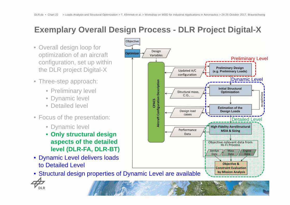
• Overall design loop for optimization of an aircraft configuration, set up within the DLR project Digital-X
• Three-step approach:• Preliminary level• Dynamic level• Detailed level
• Focus of the presentation:• Dynamic level• Only structural design
aspects of the detailed level
Exemplary Overall Design Process - DLR Project Digital-X
> Loads Analysis and Structural Optimization > T. Klimmek et al. > Workshop on MDO for Industrial Applications in Aeronautics > 24-25 October 2017, BraunschweigDLR.de • Chart 3
Dynamic Level
Preliminary Level
Detailed Level

• Overall design loop for optimization of an aircraft configuration, set up within the DLR project Digital-X
• Three-step approach:• Preliminary level• Dynamic level• Detailed level
• Focus of the presentation:• Dynamic level• Only structural design
aspects of the detailed level
Exemplary Overall Design Process - DLR Project Digital-X
> Loads Analysis and Structural Optimization > T. Klimmek et al. > Workshop on MDO for Industrial Applications in Aeronautics > 24-25 October 2017, BraunschweigDLR.de • Chart 4
Dynamic Level
Preliminary Level
Detailed Level

Load Analysis and Structural Optimization Process
> Loads Analysis and Structural Optimization > T. Klimmek et al. > Workshop on MDO for Industrial Applications in Aeronautics > 24-25 October 2017, BraunschweigDLR.de • Chart 5
• Process part of overall A/C MDO process (e.g. Digital X), but also stand alone• Subsequent explanation shows the capabilities of the process• Finally special emphasis on loads analysis with flight control system (e.g. for
maneuver load and gust load alleviation)

> Loads Analysis and Structural Optimization > T. Klimmek et al. > Workshop on MDO for Industrial Applications in Aeronautics > 24-25 October 2017, BraunschweigDLR.de • Chart 6
Model Set-up
Structural Optimization
Conv.?No
End
Start
Load case definition
Loads analysis Loads post processing
• Mass configurations(fuel, cargo, passenger)
• Design speeds• Flight envelope
(altitude, Ma)• CS 25.341
• Parametric approach
• CPACS interface• All „models“ of
the process are covered
• Maneuver• Gust• Continuous turbulence• Ground/Landing• Special load cases
• Balanced loads• Loads database• Sorting and filtering
of loads• Nodal and cutting
loads
• Gradient-based optimization
• Various optimization models
Convergence of structuralmass and loads
Loads Analysis and Structural Optimization Process

Parametric Modelling Concept – Full Model
> Loads Analysis and Structural Optimization > T. Klimmek et al. > Workshop on MDO for Industrial Applications in Aeronautics > 24-25 October 2017, BraunschweigDLR.de • Chart 7

Parametric Modelling Concept – Full Model
> Loads Analysis and Structural Optimization > T. Klimmek et al. > Workshop on MDO for Industrial Applications in Aeronautics > 24-25 October 2017, BraunschweigDLR.de • Chart 8
Geometry

Parametric Modelling Concept – Full Model
> Loads Analysis and Structural Optimization > T. Klimmek et al. > Workshop on MDO for Industrial Applications in Aeronautics > 24-25 October 2017, BraunschweigDLR.de • Chart 9
Loads Carrying Structure

Parametric Modelling Concept – Full Model
> Loads Analysis and Structural Optimization > T. Klimmek et al. > Workshop on MDO for Industrial Applications in Aeronautics > 24-25 October 2017, BraunschweigDLR.de • Chart 10
- Secondary Structure- Non-Load Carrying Structure- Other Structure

Parametric Modelling Concept – Full Model
> Loads Analysis and Structural Optimization > T. Klimmek et al. > Workshop on MDO for Industrial Applications in Aeronautics > 24-25 October 2017, BraunschweigDLR.de • Chart 11
Mass Modelling

Parametric Modelling Concept – Full Model
> Loads Analysis and Structural Optimization > T. Klimmek et al. > Workshop on MDO for Industrial Applications in Aeronautics > 24-25 October 2017, BraunschweigDLR.de • Chart 12
Interface Modeling

Parametric Modelling Concept – Full Model
> Loads Analysis and Structural Optimization > T. Klimmek et al. > Workshop on MDO for Industrial Applications in Aeronautics > 24-25 October 2017, BraunschweigDLR.de • Chart 13
Aerodynamic Model

Parametric Modelling Concept – Full Model
> Loads Analysis and Structural Optimization > T. Klimmek et al. > Workshop on MDO for Industrial Applications in Aeronautics > 24-25 October 2017, BraunschweigDLR.de • Chart 14
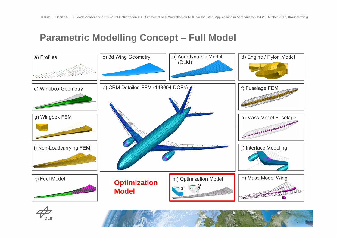
Parametric Modelling Concept – Full Model
> Loads Analysis and Structural Optimization > T. Klimmek et al. > Workshop on MDO for Industrial Applications in Aeronautics > 24-25 October 2017, BraunschweigDLR.de • Chart 15
OptimizationModel

Parametric Modelling Concept – Full Model
> Loads Analysis and Structural Optimization > T. Klimmek et al. > Workshop on MDO for Industrial Applications in Aeronautics > 24-25 October 2017, BraunschweigDLR.de • Chart 16
Condensation

Parametric Modelling Concept – Condensed Model
> Loads Analysis and Structural Optimization > T. Klimmek et al. > Workshop on MDO for Industrial Applications in Aeronautics > 24-25 October 2017, BraunschweigDLR.de • Chart 17

Load Assumption – Load Case Definition for DLR-XRF1
> Loads Analysis and Structural Optimization > T. Klimmek et al. > Workshop on MDO for Industrial Applications in Aeronautics > 24-25 October 2017, BraunschweigDLR.de • Chart 18
Parameter Nb. RemarksMass configurations 9 From OEM to MTOM
Flight levels 6 0 to 13100 m
Design speeds 6 VS, Vh, VA, Va, VC/MC, VD/MD
Stationary trim manoeuvers 9
Sym. pull-up, push down, yawing, rolling)
Gust gradients 10 9 - 107 m
Gust directions 4Vertical up and down
Horizontal left and right
Elastic modes Var. up to 40 Hz
Load cases definition in line withcorresponding paragraphs of CS25
Total Nb. ofLoad Cases:9*6*6*(9+4*10) = 15876

Design Load Selection for DLR-XRF1
> Loads Analysis and Structural Optimization > T. Klimmek et al. > Workshop on MDO for Industrial Applications in Aeronautics > 24-25 October 2017, BraunschweigDLR.de • Chart 19
Cut load envelopes for each aircraft component: shear force torque moment bending moment
Wing Bending Moment (Mx): Pull Up & Push Down up to 2/3 span Accelerated Roll and Gust in last 1/3
span Dominant cases:
o Max. take off masso cruise and diving speed o max. flight altitude
Design Loads: max & min cut forces/moments for each cut station and each degree of freedom

Mathematical formulation of the optimization problem
> Loads Analysis and Structural Optimization > T. Klimmek et al. > Workshop on MDO for Industrial Applications in Aeronautics > 24-25 October 2017, BraunschweigDLR.de • Folie 20
Structural Optimization - Capabilities
| 0; 0, 1, … , , 1, … ,
Objective : Structural mass of the load carrying structure
Design variables : Thickness of the shell elementsLamination parameter for CFRP-Material
Inequality constraints : Element stress, strain, buckling (handbook formula)Aileron efficiency, divergence dynamic pressure
Equality constraints : None.
Application of gradient based optimization algorithms (e.g. MSC Nastran)
Design Variable Models
Shear
Compression Local buckling
Maximum…Nb. of Design Variables: ~1000Nb. of Constraints: ~ 106

Example: Additional Skin Thickness due to Aileron Effectiveness Constraint – DLR-XRF1
> Loads Analysis and Structural Optimization > T. Klimmek et al. > Workshop on MDO for Industrial Applications in Aeronautics > 24-25 October 2017, BraunschweigDLR.de • Chart 21
With aileron reversal constraint sizing included:
• Increase of skin thickness up to 6 mm
• +5% wing box structure mass
• +2% root bending moment
Exemplary Overall Design Process - DLR Project Digital-X
> Loads Analysis and Structural Optimization > T. Klimmek et al. > Workshop on MDO for Industrial Applications in Aeronautics > 24-25 October 2017, BraunschweigDLR.de • Chart 22
Dynamic Level
Preliminary Level
Detailed Level
• Overall design loop for optimization of an aircraft configuration, set up within the DLR project Digital-X
• Three-step approach:• Preliminary level• Dynamic level• Detailed level
• Focus of the presentation:• Dynamic level• Only structural design
aspects of the detailed level (DLR-FA, DLR-BT)
• Dynamic Level delivers loads to Detailed Level
• Structural design properties of Dynamic Level are available

Structural Model Generators
DLR.de • Chart 23
Coupling of sub-models
• Parameterized fuselage and wing models based on CPACS input
• Fully automated coupling of sub-models using consolidated interfaces
structural components of metallic wing
structural components of metallic fuselage
> Loads Analysis and Structural Optimization > T. Klimmek et al. > Workshop on MDO for Industrial Applications in Aeronautics > 24-25 October 2017, Braunschweig

Coupling of Fuselage and Wing ModelsDLR.de • Chart 24 > Loads Analysis and Structural Optimization > T. Klimmek et al. > Workshop on MDO for Industrial Applications in Aeronautics > 24-25 October 2017, Braunschweig

Static Structural Sizing - Results
> Loads Analysis and Structural Optimization > T. Klimmek et al. > Workshop on MDO for Industrial Applications in Aeronautics > 24-25 October 2017, BraunschweigDLR.de • Chart 25
Thickness distribution
Typically 50‐60 critical SMT load cases including maneuver and gust loads

Detailed Structural Design (outlook)
> Loads Analysis and Structural Optimization > T. Klimmek et al. > Workshop on MDO for Industrial Applications in Aeronautics > 24-25 October 2017, BraunschweigDLR.de • Chart 26
Further increase of level of detailswithin FE wing model for use in MDO(e.g. integration of high-lift devices)• Parametric concept trough CPACS
integration
• Integration of enhanced failure criteria• Damage tolerance• Improved buckling criteria
by hierarchical meta-models
FE wing model withhigh-lift devices

DLR.de • Chart 27
Detailed structural optimization of CFRP componentsEfficient parametrization of composite panels• Parametrization based on Lamination Parameters Continuous & convex design space formulation
• Stringer stiffness smeared into panel representation design concept influence represented
• Calculation of panel stiffness matrix parameters for FE-model coupling simplified FE-model
Optimization process• Global FE-model to calculate forces and displacements• Object model with analytical panel representation• Highly parallel, full gradient estimation• lamination parameters transformed into layupsOptimization Constraints• Static strength criteria (buckling, column buckling,
strength, damage tolerance) & stiffness • Consideration of manufacturing criteria (i.e. ply
continuity) including gradient calculation
> Loads Analysis and Structural Optimization > T. Klimmek et al. > Workshop on MDO for Industrial Applications in Aeronautics > 24-25 October 2017, Braunschweig

• Parametric loads analysis and structural optimization process, working in different design and MDO environments, has a wide range of capabilities
• Extension of the structural optimization part (e.g. fatigue constraints )• Extension of the loads analysis part (e.g. appropriate fatigue analysis, aero
correction methods)• Extension of the modelling part (e.g. fem of the fuselage for the Dynamic Level
with same level of detail as the wings) • Use of the loads and structural optimization process for gradient-based hi-fi
aero-structural MDO• Further development of interfacing with Detailed Level
• Loads analysis with closed-loop flight control system for maneuver- and gust load alleviation presented by Thiemo Kier (DLR-SR)…
Summary and Outlook
> Loads Analysis and Structural Optimization > T. Klimmek et al. > Workshop on MDO for Industrial Applications in Aeronautics > 24-25 October 2017, BraunschweigDLR.de • Chart 28
Loads Analysis and Structural Optimization –Flight Control System Design as part of MDO
1st European Workshop on MDO for Industrial Applications in Aeronautics24th-25th October 2017, Braunschweig
Thiemo KierDLR OberpfaffenhofenInstitute of System Dynamics & Control
> MDO: Loads and FCS Design > Thiemo Kier • DLR-SR > 25.10.2017DLR.de • Chart 1

> MDO: Loads and FCS Design > Thiemo Kier • DLR-SR > 25.10.2017DLR.de • Chart 2
Anderson M.A. and Mason, W., „An MDO Approach to Control-Configured-Vehicle Design“, 6th AIAA/NASA/ISSMO Symposium on Multidisciplinary Analysis and Optimization, Bellevue, 1996
Flight Control System Design in the MDO loop

Why is this important for the loads process?
> MDO: Loads and FCS Design > Thiemo Kier • DLR-SR > 25.10.2017DLR.de • Chart 3
CS 25.302 Interaction of systems and structuresFor aeroplanes equipped with systems that affect structural performance,…Appendix K of CS25 must be used to evaluate the structural performance of aeroplanes equipped with these systems.
CS-25 Appendix K: Interaction of Systems and Structure• flight control systems, • autopilots, • stability augmentation systems,
• load alleviation systems, • flutter control systems, and • fuel management systems.

Loads Analysis Model> MDO: Loads and FCS Design > Thiemo Kier • DLR-SR > 25.10.2017DLR.de • Chart 4
Loads
AM
S
K
Aerodynamics Mass
StiffnessFlight Control System
Aerodynamicss
Stiffness• Control Surface Allocation• Manoeuvre and Gust
Load Alleviation Functions• Primary Flight Control
Laws• Sensors• Actuators

> MDO: Loads and FCS Design > Thiemo Kier • DLR-SR > 25.10.2017DLR.de • Chart 5
Design Variables
LoadsModel
AM
S
K
Model Integration
Loads Analysis
Structural Sizing
Specify load cases
Update stiffnessand mass
Critical load casesand loads on ref. axis
LoadRecovery /CorrelatedloadsConvergence
Critical loads andload cases
Loads Process
Critical load cases
Model Generation
Load Loops
Aerodynamics MassStiffnessStiffnessStiffnFlight Control
System
Sorting andEnvelopping
Loads Analysis
Load
Loads Analysis

Control Surface Allocation: Roll Manoeuvre
1 2
• Using the outboard aileron for roll control at high dynamic pressures results in an reversal of the aileron.
• Employing a structural c/s reversal constraint increases the mass
• Allocation/Scheduling wrt. Velocity, e.g. using roll spoilers and/or split or inboard ailerons at high dynamic pressures
> MDO: Loads and FCS Design > Thiemo Kier • DLR-SR > 25.10.2017DLR.de • Chart 6

Load Alleviation Functions
• When no MLA is considered, the manoeuvre cases will likely always be critical• With MLA, manoeuvre and gust loads have the same level• If the wing loading is low, gust loads will become critical and a GLA is needed
• Which C/S to use for LAF? Special C/S? Multifunctional C/S?• Design of Flight Control System needs to be part of the MDO task.
(Control Surface Placement, Allocation and Control Laws)
> MDO: Loads and FCS Design > Thiemo Kier • DLR-SR > 25.10.2017DLR.de • Chart 7

• Simulation and Stochastic Analysis of Continuous Turbulence Load Cases• Nonlinear Effects of Control Law on Structural Loads
Open Loop
Closed Loop
Power Spectral DensityLevel Crossings
Time Domain Continuous TurbulenceLateral cont. turbulence (Dryden Spectrum)
Correlated Loads DistributionsAccounting for Nonlinear Effects such as
SaturationRate limitsTriggered activation
> MDO: Loads and FCS Design > Thiemo Kier • DLR-SR > 25.10.2017DLR.de • Chart 8

• Model based, automated dynamic EFCS generation• Based on HQ and architecture specifications• Robust approach required• Nonlinear Dynamic Inversion based EFCS prototype for MDO processes
Fully Parameterized Prototype EFCS Generation
> MDO: Loads and FCS Design > Thiemo Kier • DLR-SR > 25.10.2017DLR.de • Chart 9
Control ofAngular
Accelerations
Attitude ControlAutoflightFunctions:
(Auto-Throttle,DLC, etc.)
TrajectoryFollowingFunctions
(for Mission-simulations)
Auto-TrimSignalProcessing

Yaw manoeuvre CS 25.351• dependent on architecture of the controller (deflection limiter, yaw damper, control
laws) and the flight mechanics (Dutch Roll) of the aircraft.• Yaw manoeuvres are critical load cases for VTP sizing
Mishap during an MDO run:• Due to a wrong setting RTL was not active, resulting in a very heavy VTP • and suddenly yaw manoeuvres appeared as critical cases for wing design
1. Onset 2. Overswing Yaw
3. Equilibrium Yaw 4. Rudder Return
= 0° = max
= steady = steady
r = r
r r
Flight Controller: Phases of the yaw manoeuvre:
> MDO: Loads and FCS Design > Thiemo Kier • DLR-SR > 25.10.2017DLR.de • Chart 10

Text:
• Text
41 2 3
Bending and torsion moments at the VTP root
> MDO: Loads and FCS Design > Thiemo Kier • DLR-SR > 25.10.2017DLR.de • Chart 11Dynamic Simulation of the Yaw Manoeuvre

VTP Loads Comparison Dynamic Simulation andTrim
Text:
• Text
1
3
4
onset
Equilibriumyaw
Rudder return
2
Overswing
> MDO: Loads and FCS Design > Thiemo Kier • DLR-SR > 25.10.2017DLR.de • Chart 12

Example: Increasing the span to reduce induced drag
• Chord length at wing root is constrained due to landing gear integration• Thus, the wing area increases
Optimization Parameters : Control Surface -placement, -dimensioning, -allocation, -function assignment, -control
DLR.de • Chart 13
Aircraft Design Example –Interaction Flight Control and Flight Physics (Loads / HQ)
Loads Analysis – Load AlleviationFunctions• Wing Loading decreases• Gust Loads become critical in the Loads
Envelope• Active Gust Load Alleviation required• Side constraint: HTP Loads are
increasing
Flight Dynamics – Primary Flight Control Laws
• Rolldamping CLp is increased• Handling Quality constraint: Rolling
bank to bank +30° to -30° in 7 s
Loads Analysis – Load AlleviationFunctions• Wing Loading decreases• Gust Loads become critical in the Loads
Envelope• Active Gust Load Alleviation required• Side constraint: HTP Loads are
gincreasing
Flight Dynamics – Primary Flight Control Laws
• Rolldamping CLpC is increased• Handling Quality constraint: Rolling
bank to bank +30° to -30° in 7 s
> MDO: Loads and FCS Design > Thiemo Kier • DLR-SR > 25.10.2017

DLR.de • Chart 14 > MDO: Loads and FCS Design > Thiemo Kier • DLR-SR > 25.10.2017
Thank you for your attention !Questions ?