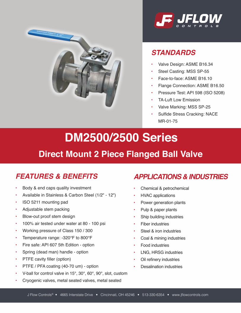
dm2500/2500 series -...
TRANSCRIPT
APPLICATIONS & INDUSTRIES• Chemical & petrochemical• HVAC applications• Power generation plants• Pulp & paper plants• Ship building industries• Fiber industries• Steel & iron industries• Coal & mining industries• Food industries• LNG, HRSG industries• Oil refinery industries• Desalination industries
FEATURES & BENEFITS• Body & end caps quality investment• Available in Stainless & Carbon Steel (1/2" - 12")• ISO 5211 mounting pad• Adjustable stem packing• Blow-out proof stem design• 100% air tested under water at 80 - 100 psi• Working pressure of Class 150 / 300• Temperature range: -320°F to 800°F• Fire safe: API 607 5th Edition - option• Spring (dead man) handle - option• PTFE cavity filler (option)• PTFE / PFA coating (40-70 um) - option• V-ball for control valve in 15°, 30°, 60°, 90°, slot, custom• Cryogenic valves, metal seated valves, metal seated
STANDARDS• Valve Design: ASME B16.34• Steel Casting: MSS SP-55• Face-to-face: ASME B16.10• Flange Connection: ASME B16.50• Pressure Test: API 598 (ISO 5208)• TA-Luft Low Emission• Valve Marking: MSS SP-25• Sulfide Stress Cracking: NACE
MR-01-75
DM2500/2500 SeriesDirect Mount 2 Piece Flanged Ball Valve
J Flow Controls® • 4665 Interstate Drive • Cincinnati, OH 45246 • 513-330-6354 • www.jflowcontrols.com
Page 2
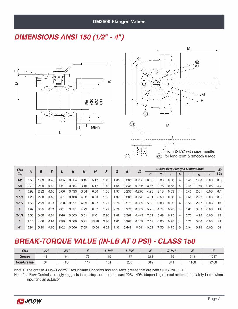
DM2500 Flanged Valves
DIMENSIONS ANSI 150 (1/2" - 4")
Size (in) A B E L H K M F G d1 d2
Class 150# Flanged Dimensions WtLbsD C h N t g f
1/2 0.59 1.89 0.43 4.25 0.354 3.15 5.12 1.42 1.65 0.236 0.236 3.50 2.38 0.63 4 0.45 1.38 0.06 3.8
3/4 0.79 2.09 0.43 4.61 0.354 3.15 5.12 1.42 1.65 0.236 0.236 3.86 2.76 0.63 4 0.45 1.69 0.06 4.71 0.98 2.32 0.55 5.00 0.433 3.54 6.50 1.65 1.97 0.236 0.276 4.25 3.13 0.63 4 0.45 2.01 0.06 6.4
1-1/4 1.26 2.80 0.55 5.51 0.433 4.02 6.50 1.65 1.97 0.236 0.276 4.61 3.50 0.63 4 0.50 2.52 0.06 8.8
1-1/2 1.50 2.99 0.71 6.50 0.551 4.33 8.07 1.97 2.76 0.276 0.362 5.00 3.88 0.63 4 0.56 2.87 0.06 13
2 1.97 3.35 0.71 7.01 0.551 4.72 8.07 1.97 2.76 0.276 0.362 5.98 4.74 0.75 4 0.63 3.62 0.06 19
2-1/2 2.56 3.68 0.91 7.48 0.669 5.51 11.81 2.76 4.02 0.362 0.449 7.01 5.49 0.75 4 0.70 4.13 0.06 29
3 3.15 4.06 0.91 7.99 0.669 5.91 13.39 2.76 4.02 0.362 0.449 7.48 6.00 0.75 4 0.75 5.00 0.06 38
4" 3.94 5.20 0.98 9.02 0.866 7.09 16.54 4.02 4.92 0.449 0.51 9.02 7.50 0.75 8 0.94 6.18 0.06 64
Size 1/2" 3/4" 1" 1-1/4" 1-1/2" 2" 2-1/2" 3" 4"
Grease 49 64 78 115 177 212 478 549 1097
Non-Grease 64 83 117 161 266 319 841 1168 2168
BREAK-TORQUE VALUE (IN-LB AT 0 PSI) - CLASS 150
Note 1: The grease J Flow Control uses include lubricants and anti-seize grease that are both SILICONE-FREENote 2: J Flow Controls strongly suggests increasing the torque at least 20% - 40% (depending on seat material) for safety factor when mounting an actuator
BE
L
K
ØD
ØC
ØB
ØA
Øh-nft
20
M
FG
d1d2
M
H
From 2-1/2" with pipe handle, for long term & smooth usage
21
22 23

Page 2 Page 3
DM2500 Flanged Valves
DIMENSIONS ANSI 300 (1/2" - 4")
Size (in) A F E L K M G J
Class 300# Flanged DimensionsD C H N t g B O f
1/2 0.59 2.99 5.71 5.50 0.26 1.65 M5 0.39 3.74 2.62 0.63 4 0.57 1.38 0.55 0.42 0.06
3/4 0.79 3.15 5.71 6.00 0.26 1.65 M5 0.39 4.61 3.25 0.75 4 0.63 1.69 0.56 0.43 0.061 0.98 3.46 7.68 6.50 0.38 1.97 M6 0.55 4.88 3.50 0.75 4 0.69 2.01 0.85 0.66 0.06
1-1/4 - - - - - - - - - - - - - - - - -
1-1/2 1.50 4.49 7.50 7.50 0.38 2.76 M8 0.71 6.14 4.51 0.87 4 0.83 2.87 0.98 0.71 0.06
2 1.97 4.84 8.50 8.50 0.38 2.76 M8 0.71 6.50 5.00 0.79 8 0.89 3.62 0.94 0.77 0.06
2-1/2 2.56 5.59 9.50 9.50 0.47 4.02 M10 0.79 7.48 5.87 0.87 8 1.00 4.13 0.90 0.64 0.06
3 3.15 5.98 11.13 11.13 0.47 4.02 M10 0.79 8.27 6.61 0.87 8 1.14 5.00 0.86 0.64 0.06
4" 3.94 7.17 12.00 12.00 0.59 4.02 M10 0.94 10.00 7.87 0.87 8 1.26 6.18 1.17 0.96 0.06
Size 1/2" 3/4" 1" 1-1/4" 1-1/2" 2" 2-1/2" 3" 4"
Grease 73 87 113 - 238 298 631 749 1385
Non-Grease 102 121 170 - 238 537 1262 1572 2909
BREAK-TORQUE VALUE (IN-LB AT 0 PSI) - CLASS 300
Note 1: The grease J Flow Control uses include lubricants and anti-seize grease that are both SILICONE-FREENote 2: J Flow Controls strongly suggests increasing the torque at least 20% - 40% (depending on seat material) for safety factor when mounting an actuator
E
L
FgC DA
H-N (# Holes)f
t M
K
JG
E
From 2-1/2" with pipe handle, for long term & smooth usage

Page 4
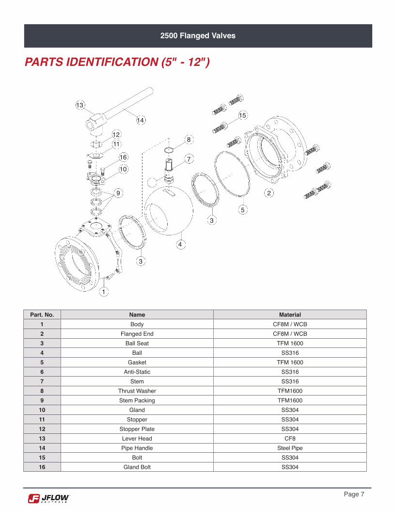
DM2500 Flanged Valves
PARTS IDENTIFICATION (1/2" - 4")
Part. No. Name Stainless Steel Carbon Steel Part
No. Name Stainless Steel Carbon Steel
1 Body CF8M A216 WCB 13 Gasket TFM TFM2 Stem 316SST 304SST 14 Ball 316SST 304SST3 Thrust Washer TFM TFM 15 Ball Seat TFM TFM4 O-ring Viton Viton 16 Stopper Plate 304SST 304SST5 Stem Bearing TFM TFM 17 Handle Nut 304SST 304SST6 Gland 304SST 304SST 18 Handle 304SST 304SST7 Stem Washer 301SST 301SST 19 Sleeve Vinyl Vinyl8 Stem Nut 304SST 304SST 20 Stop Pin 304SST 304SST9 Nut Stop 304SST 304SST 21 Set Bolt 304SST 304SST
10 Washer 304SST 304SST 22 Lever Head CF8 CF811 Flanged End CF8M A216 WCB 23 Pipe Handle Steel Pipe Steel Pipe12 Bolt 304SST 304SST
22
21
22
1314
14
15
43
2
1
5
67
8910
16
18
17
19
11
20
1220-1

Page 4 Page 5
2500 Flanged Valves
FEATURES & BENEFITS (5" - 12")• Body & end caps sand casting• Available in Stainless & Carbon Steel • ISO 5211 mounting pad• Adjustable stem packing• Blow-out proof stem design• 100% air tested under water at 80 - 100 psi• Working pressure of Class 150 / 300• Temperature range: -320°F to 800°F
Options (5" - 12")• Fire safe design• Gear operator / pneumatic and electric actuator• PTFE cavity filler• PTFE coating (40 - 70 um)• Direct mount bracket• Alloy 20 / Monel / Titanium / Hastelloy C / Super Duplex• V-ball for control valve in 30°, 60°, 90°, and custom• Cryogenic valves• Fugitive emissions bonnet• Metal seated
Size 5" 6" 8" 10" 12"
Grease 2036 2213 4868 5753 10620
Non-Grease - - - - -
Size Cv Factor
5" 3350
6" 50008" 10000
10" 1500012" 21000
BREAK-TORQUE VALUE (IN-LB AT 0 PSI)
FLOW COEFFICIENT
Note 1: The grease J Flow Control uses include lubricants and anti-seize grease that are both SILICONE-FREENote 2: J Flow Controls strongly suggests increasing the torque at least 20% - 40% (depending on seat material) for safety factor when mounting an actuator
PRESSURE / TEMPERATURE CHART800
700
600
500
400
300
200
100
0-320 0 100 200 300 400 500 600 700 800 900
Class 150
Class 300
TFM1600
TFM4215
PEEK
Carbon PEEK
Metal
Pres
sure
(PSI
)
Temperature °F

Page 6
2500 Flanged Valves
DIMENSIONS
Size (in) A B E F G H M L K S
Class 150# Flanged DimensionsD C n h g t f
5 4.92 5.91 2.28 1.34 4.92 10.43 27.56 14.02 M12 1.06 10.00 8.50 8 0.87 7.32 0.94 0.06
6 5.91 6.69 2.28 1.34 4.92 11.22 33.46 15.51 M12 1.06 10.98 9.51 8 0.87 8.50 1.00 0.068 7.87 8.62 2.52 1.50 4.92 13.94 43.31 17.99 M12 1.42 13.50 11.75 8 0.87 10.63 1.13 0.06
10 9.84 10.04 2.52 1.50 4.92 15.35 47.24 20.98 M12 1.42 15.98 14.25 12 0.98 12.76 1.19 0.06
12 11.81 12.09 3.11 1.81 5.51 17.40 59.06 24.02 M16 1.42 19.02 17.01 12 0.98 15.00 1.25 0.06
Size (in) A B E F G H M L K S
Class 300# Flanged DimensionsD C n h g t f
6 5.91 6.87 2.11 1.24 4.92 11.34 33.46 15.87 M12 1.06 12.52 10.63 12 0.87 8.50 1.46 0.06
8 7.87 8.64 2.52 1.50 4.92 13.50 43.31 19.76 M12 1.42 15.00 13.00 12 1.02 10.63 1.63 0.06
DIMENSIONS ANSI 150 5" - 12"
DIMENSIONS ANSI 300 6" - 8"
M
FEB
1.30 H
DCgA
h-nf
t
3.171.70
5.51
S
K GL
8" - 12"5" - 6"
4.49
2.581.40
S
K GL
Page 6 Page 7
2500 Flanged Valves
Part. No. Name Material1 Body CF8M / WCB2 Flanged End CF8M / WCB3 Ball Seat TFM 16004 Ball SS3165 Gasket TFM 16006 Anti-Static SS3167 Stem SS3168 Thrust Washer TFM16009 Stem Packing TFM1600
10 Gland SS30411 Stopper SS30412 Stopper Plate SS30413 Lever Head CF814 Pipe Handle Steel Pipe15 Bolt SS30416 Gland Bolt SS304
PARTS IDENTIFICATION (5" - 12")
13
14
1211
16
10
8
7
15
2
53
4
3
1
9
2500 Flanged Valves
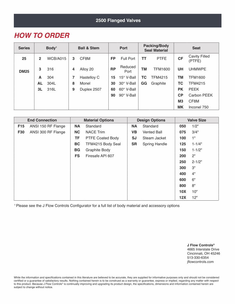
HOW TO ORDERSeries Body1 Ball & Stem Port Packing/Body
Seal Material Seat
25 2 WCB/A015 3 CF8M FP Full Port TT PTFE CF Cavity Filled (PTFE)
DM25 3 316 4 Alloy 20 RP Reduced
Port TM TFM1600 UH UHMWPE
A 304 7 Hastelloy C 15 15° V-Ball TC TFM4215 TM TFM1600AL 304L 8 Monel 30 30° V-Ball GG Graphite TC TFM42153L 316L 9 Duplex 2507 60 60° V-Ball PK PEEK
90 90° V-Ball CP Carbon PEEKM3 CF8MMK Inconel 750
J Flow Controls®
4665 Interstate DriveCincinnati, OH 45246513-330-6354jflowcontrols.com
While the information and specifications contained in this literature are believed to be accurate, they are supplied for informative purposes only and should not be considered certified or a guarantee of satisfactory results. Nothing contained herein is to be construed as a warranty or guarantee, express or implied, regarding any matter with respect to this product. Because J Flow Controls® is continually improving and upgrading its product design, the specifications, dimensions and information contained herein are subject to change without notice.
End Connection Material Options Design Options Valve SizeF15 ANSI 150 RF Flange NA Standard NA Standard 050 1/2"F30 ANSI 300 RF Flange NC NACE Trim VB Vented Ball 075 3/4"
TF PTFE Coated Body SJ Steam Jacket 100 1"BC TFM4215 Body Seal SR Spring Handle 125 1-1/4"BG Graphite Body 150 1-1/2"FS Firesafe API 607 200 2"
250 2-1/2"300 3"400 4"600 6"800 8"10X 10"12X 12"
1 Please see the J Flow Controls Configurator for a full list of body material and accessory options