dm_manual fan clutch.pdf
TRANSCRIPT
Fan Drive Maintenance Training Manual
22742M-B-0202

2 22742M-A-0901
TABLE OF CONTENTS
INTRODUCTION ......................................................................................................... 3General Information.............................................................................................. 3
LESSON 1: FAN DRIVE SYSTEM ............................................................................ 41. Operation .......................................................................................................... 42. Control System ................................................................................................ 5
LESSON 2: CONTROL COMPONENTS ................................................................... 61. Engine Coolant Thermal Switch ....................................................................... 62. Refrigerant Pressure Switch ............................................................................ 63. Solenoid Valve .................................................................................................. 7
LESSON 3: ELECTRICAL CONTROL SYSTEMS (ECM) ........................................ 81. Electronic Control Module................................................................................ 82. Sensors ............................................................................................................ 9
LESSON 4: ELECTRICAL CONTROL SYSTEMS (NON-ECM) ............................. 101. Types of Electrical Control Systems ............................................................. 102. Normally-Open Electrical Controls ................................................................ 113. Normally-Closed Electrical Controls .............................................................. 124. Comparison - Open/Closed Electrical Controls ............................................ 135. Summary ........................................................................................................ 13
LAB ACTIVITY - FAN DRIVE CONTROL COMPONENTS .................................... 14REVIEW QUESTIONS - FAN DRIVE CONTROL SYSTEMS ................................ 15
Review Answers - Fan Drive Control Systems ................................................ 18PRIOR TO SERVICING ........................................................................................... 21LESSON 5: DRIVEMASTER PARTS AND REPAIR KITS .................................... 22
1. Parts Identification ........................................................................................ 222. Repair Kits ..................................................................................................... 23
1. DriveMaster Seal Kit (Part #994346) ..................................................... 232. DriveMaster Super Kit (Part #994347) .................................................. 243. DriveMaster Friction Disc Kit (Part #994348) ....................................... 244. DriveMaster Friction Liner Kit (Part #994349) ...................................... 24
LESSON 6: REMOVING THE FAN DRIVE ............................................................ 26LESSON 7: DISASSEMBLING THE FAN DRIVE ................................................. 27
1. Tools Required ............................................................................................... 272. Disassembly .................................................................................................. 27
Fan Mounting Disc Removal and Inspection ............................................. 27Spring Housing/Piston Assembly Removal ............................................... 29Air Chamber Seals ...................................................................................... 30Sheave and Sheave Bearings .................................................................... 30Air Cartridge Removal ................................................................................ 31
LESSON 8: REBUILDING THE FAN DRIVE ......................................................... 311. Torque Specifications .................................................................................... 312. Rebuilding ...................................................................................................... 31
Sheave Bearing Replacement ................................................................... 31Air Cartridge ................................................................................................ 32Spring Housing/Piston Assembly Reassembly ......................................... 33Fan Mounting Disc Reassembly ................................................................ 34
LESSON 9: REINSTALLING THE FAN DRIVE ..................................................... 35LESSON 10: PREVENTIVE MAINTENANCE (PM) .............................................. 36
1. Introduction .................................................................................................... 362. Weekly PM ..................................................................................................... 363. 25,000 Mile [40,000 Km] PM ........................................................................ 37
LESSON 11: TROUBLESHOOTING ...................................................................... 38REVIEW QUESTIONS - FAN DRIVE SERVICE .................................................... 41
Review Answers - Fan Drive Service ............................................................... 44FINAL TEST ............................................................................................................. 47
Final Test Answers ............................................................................................ 52
322742M-B-0202
IntroductionThis student manual for the technical course, DriveMaster Heavy Duty Fan Drive Maintenance, is designed to train heavyduty diesel technicians how to perform preventive and corrective maintenance on Horton heavy duty DriveMaster FanDrives.
The manual, video and CD may be used in the classroom with an instructor or in a self-study mode. After completion of thiscourse, take the Final Test at the end of this student manual. Mail your Final Test to the following address to receive aCertified Horton Technician toolbox sticker and a Horton Certificate of Achievement:
Horton, Inc.2565 Walnut St.
Roseville, MN 55113651-361-6400
1-800-621-1320Website: www.hortoninc.comE-mail: [email protected]
In accordance with Horton’s established policy of constant product improvement, the specifications contained in this manual aresubject to change without notice and are based on the latest information available at the time of printing.
INTRODUCTION
General Information
Horton uses the following special notices to give warning of possible safety related problems which could cause seriousinjury and provide information to help prevent damage to equipment.
Danger is used to indicate the presence of a hazard which will causesevere personal injury, death, or substantial property damage if the
warning is ignored.
Warning is used to indicate the presence of a hazard which can causesevere personal injury, death, or substantial property damage if the
warning is ignored.
Caution is used to indicate the presence of a hazard which will orcan cause minor personal injury or property damage if the warning is
ignored.
NOTENote is used to notify people of installation, operation, or
maintenance information which is important but not hazard related.

4 22742M-B-0202
Learning Objectives• Recognize the purpose and
advantages of a Fan Drive.
Heavy Duty Fan Drive
Radiator
NOTE:An engaged Fan Drive pulls airthrough the radiator to cool theengine.
When engaged, the Fan Drive activates the fan to cool the engine by pulling air throughthe radiator. Depending on the size and rotational speed of the fan, as much as 70-75 HPmay be needed to run the Fan. The Fan Drive engages only when needed resulting inadditional horsepower for drive axles, less noise, and increased fuel economy. Due tothese benefits, most new diesel powered vehicles are equipped with a Horton On/Off FanDrive.
Fan
LESSON 1: FAN DRIVE SYSTEM
1.1 Operation

522742M-B-0202
The illustration above depicts an independent Fan Drive control system. The electricallycontrolled solenoid valve engages and disengages the Fan Drive by regulating its air pres-sure on and off.
The electrical circuit to the solenoid valve contains three switches. Any of these threeswitches may activate the solenoid and engage the Fan Drive:
• a thermal switch sensing the engine coolant temperature.
• a refrigerant pressure switch in the vehicle’s air conditioning system.
• an optional manual override switch located on the vehicle’s dashboard.
The DriveMaster Fan Drive is spring-engaged and disengages when air pressure is applied.
Most newer vehicles are equipped with an Electronic Control Module (ECM), which is asmall computer that monitors and controls all engine operations, including the Fan Drive.If a vehicle uses an ECM, there is no direct connection between the sensors and thesolenoid valve for the Fan Drive. Information from sensors and switches is fed into theECM which controls the solenoid valve.
To Ignition
Learning Objectives• Describe the basic operation of
the Fan Drive control system.
• Identify the components of a FanDrive electrical control system.
• Describe how air pressureengages/disengages theDriveMaster Fan Drive.
Solenoid Valve
Air Supply
Air Filter
A/C Refrigerant Pressure Switch
Thermal Switch
ManualOverride Switch
Fan Drive
1.2 Control System
EXAMPLE. When the engine coolant temperature rises above the thermal switch’sset point, the thermal switch activates the solenoid valve, which shuts off air pressure
to the Fan Drive (supplied by the vehicle’s air reservoir) and engages the fan.
6 22742M-B-0202
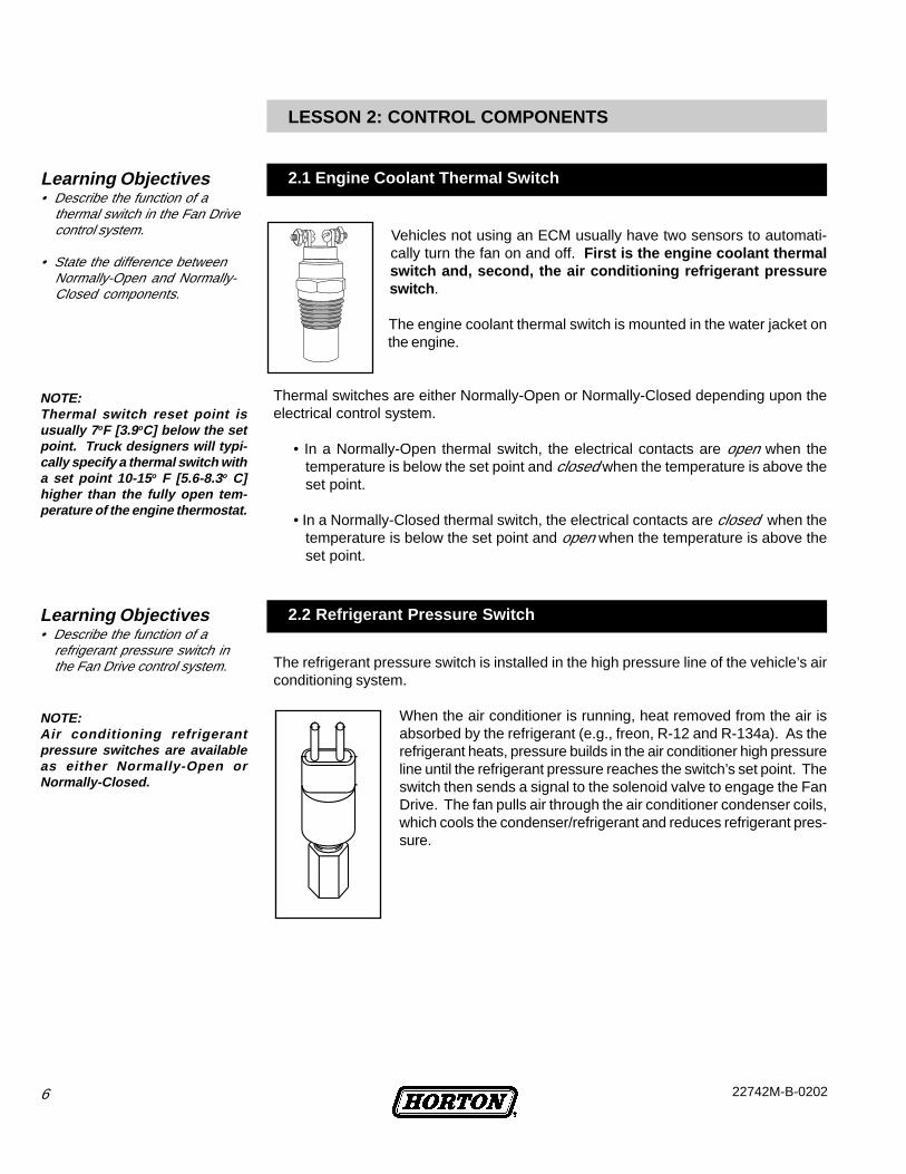
Vehicles not using an ECM usually have two sensors to automati-cally turn the fan on and off. First is the engine coolant thermalswitch and, second, the air conditioning refrigerant pressureswitch .
The engine coolant thermal switch is mounted in the water jacket onthe engine.
Thermal switches are either Normally-Open or Normally-Closed depending upon theelectrical control system.
• In a Normally-Open thermal switch, the electrical contacts are open when thetemperature is below the set point and closed when the temperature is above theset point.
• In a Normally-Closed thermal switch, the electrical contacts are closed when thetemperature is below the set point and open when the temperature is above theset point.
The refrigerant pressure switch is installed in the high pressure line of the vehicle’s airconditioning system.
When the air conditioner is running, heat removed from the air isabsorbed by the refrigerant (e.g., freon, R-12 and R-134a). As therefrigerant heats, pressure builds in the air conditioner high pressureline until the refrigerant pressure reaches the switch’s set point. Theswitch then sends a signal to the solenoid valve to engage the FanDrive. The fan pulls air through the air conditioner condenser coils,which cools the condenser/refrigerant and reduces refrigerant pres-sure.
NOTE:Thermal switch reset point isusually 7 oF [3.9oC] below the setpoint. Truck designers will typi-cally specify a thermal switch witha set point 10-15 o F [5.6-8.3o C]higher than the fully open tem-perature of the engine thermostat.
NOTE:Air conditioning refrigerantpressure switches are availableas either Normally-Open orNormally-Closed.
Learning Objectives• Describe the function of a
thermal switch in the Fan Drivecontrol system.
• State the difference betweenNormally-Open and Normally-Closed components.
Learning Objectives• Describe the function of a
refrigerant pressure switch inthe Fan Drive control system.
LESSON 2: CONTROL COMPONENTS
2.1 Engine Coolant Thermal Switch
2.2 Refrigerant Pressure Switch
722742M-B-0202
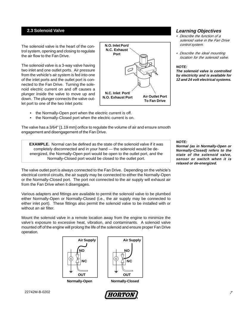
The solenoid valve is the heart of the con-trol system, opening and closing to regulatethe air flow to the Fan Drive.
The solenoid valve is a 3-way valve havingtwo inlet and one outlet ports. Air pressurefrom the vehicle’s air system is fed into oneof the inlet ports and the outlet port is con-nected to the Fan Drive. Turning the sole-noid electric current on and off causes aplunger inside the valve to move up anddown. The plunger connects the valve out-let port to one of the two inlet ports:
• the Normally-Open port when the electric current is off.• the Normally-Closed port when the electric current is on.
The valve has a 3/64" [1.19 mm] orifice to regulate the volume of air and ensure smoothengagement and disengagement of the Fan Drive.
The valve outlet port is always connected to the Fan Drive. Depending on the vehicle’selectrical control circuits, the air supply may be connected to either the Normally-Openor the Normally-Closed port. The port not connected to the air supply will exhaust airfrom the Fan Drive when it disengages.
Various adapters and fittings are available to permit the solenoid valve to be plumbedeither Normally-Open or Normally-Closed (i.e., the air supply may be connected toeither inlet port). These fittings also permit the solenoid valve to be installed with orwithout an air filter.
Mount the solenoid valve in a remote location away from the engine to minimize thevalve’s exposure to excessive heat, vibration, and contaminants. A solenoid valvemounted off of the engine will prolong the life of the solenoid and ensure proper Fan Driveoperation.
NOTE:Normal (as in Normally-Open orNormally-Closed) refers to thestate of the solenoid valve,sensor or switch when it isrelaxed or de-energized.
NOTE:The solenoid valve is controlledby electricity and is available for12 and 24 volt electrical systems.
Learning Objectives• Describe the function of a
solenoid valve in the Fan Drivecontrol system.
• Describe the ideal mountinglocation for the solenoid valve.
2.3 Solenoid Valve
EXAMPLE. Normal can be defined as the state of the solenoid valve if it wascompletely disconnected and in your hand — the solenoid would be de-
energized, the Normally-Open port would be open to the outlet port, and theNormally-Closed port would be closed to the outlet port.
N.C. Inlet Port/N.O. Exhaust Port Air Outlet Port
To Fan Drive
N.O. Inlet Port/N.C. Exhaust
Port
Air Supply
NO
NC
OUT
Air Supply
NO
NC
OUT
Normally-Open Normally-Closed
8 22742M-B-0202
The electrical wiring that controls the Fan Drive varies from one vehicle to another, butgenerally will be one of three types of systems:
• ECM controlled• Normally-Open• Normally-Closed
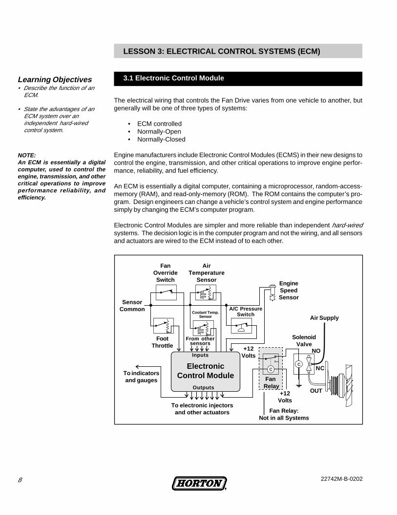
Engine manufacturers include Electronic Control Modules (ECMS) in their new designs tocontrol the engine, transmission, and other critical operations to improve engine perfor-mance, reliability, and fuel efficiency.
An ECM is essentially a digital computer, containing a microprocessor, random-access-memory (RAM), and read-only-memory (ROM). The ROM contains the computer’s pro-gram. Design engineers can change a vehicle’s control system and engine performancesimply by changing the ECM’s computer program.
Electronic Control Modules are simpler and more reliable than independent hard-wiredsystems. The decision logic is in the computer program and not the wiring, and all sensorsand actuators are wired to the ECM instead of to each other.
NOTE:An ECM is essentially a digitalcomputer, used to control theengine, transmission, and othercritical operations to improveperformance reliability, andefficiency.
Learning Objectives• Describe the function of an
ECM.
• State the advantages of anECM system over anindependent hard-wiredcontrol system.
LESSON 3: ELECTRICAL CONTROL SYSTEMS (ECM)
3.1 Electronic Control Module
Fan Relay:Not in all Systems
FanOverrideSwitch
SensorCommon
FootThrottle
To indicatorsand gauges
Coolant Temp.Sensor
From othersensors
Inputs
ElectronicControl Module
Outputs
To electronic injectorsand other actuators
AirTemperature
Sensor
A/C PressureSwitch
EngineSpeedSensor
Air Supply
SolenoidValve
Fan Relay
+12Volts
NO
NC
OUT
+12Volts
922742M-B-0202
In an ECM controlled system, one sensor may affect several actuators and one actuatormay be affected by several sensors, depending on how the ECM is programmed.
Sensors used in ECM systems are different than those used in independent systems.Instead of the simple open/close type of sensor, ECM systems use thermistors andsending units to send signals to the ECM (temperature, pressure, speed, or whateverfunction is being sensed).
NOTE:The ECM program considersseveral factors before determin-ing Fan Drive engagement.
EXAMPLE. Instead of a thermal switch opening or closing at a preset temperature,ECM’s use a temperature sensor to provide voltage which the logic program
converts into an actual temperature measurement. Instead of simply knowing if thecoolant temperature is above or below the set point (i.e., hotter that 190o F [88o C]),
the program knows the actual temperature (i.e., 196.4o F [91.3o C]).
The Fan Drive solenoid is not wired to the sensors as it is in a conventional system butinstead wired to a relay controlled by the ECM. The ECM computer program looks at thedata from several sensors and decides when to engage and disengage the Fan Drive.The program considers engine coolant temperature, air-conditioner’s refrigerant pres-sure, intake-manifold air temperature, engine speed, and the engine brake status.
New troubleshooting techniques may be necessary when working on a truck with anECM control system. A vehicle’s wiring diagram no longer indicates which sensor af-fects which actuator. The diagram only shows which ECM pin each sensor and actuatoris connected. To determine the relationships between the sensors and actuators,refer to the vehicle or engine service manual for descriptions of exact conditionsunder which each actuator is engaged (i.e. Fault Codes).
NOTE:The ECM monitors data from thesensors to send signals to thecontrols, actuators, andoperator’s warning lights andgauges.
Learning Objectives• Describe the basic operation of
an ECM-Controlled System.
• Describe how ECM sensorsoperate differently thanswitches used in independenthard-wired systems.
• Trace the path of a sensorsignal to Fan Drive operation inan ECM-controlled system.
The diagram on the previous page shows that the sensors are not wired to the solenoidvalve or any control actuator as in a conventional system. Instead, each sensor goes toan ECM input pin and each actuator is wired to an ECM output pin. The ECM computermonitors the data from the sensors and sends the appropriate signals to the controls andactuators based on programming logic. The ECM also sends status information to theoperator’s warning lights and gauges.
3.2 Sensors
10 22742M-B-0202
The electrical wiring that controls the Fan Drive varies from one vehicle to another, butgenerally will be one of three types of systems:
• ECM controlled• Normally-Open• Normally-Closed
Most newer engine designs are ECM controlled. Prior to ECM systems, manufacturersthat tended to have Normally-Closed electrical controls include:
Blue BirdGMCMackFordNavistar / InternationalWhite GMC
Prior to ECM systems, manufacturers that tended to have Normally-Open electricalcontrols include:
FreightlinerMackWestern StarKenworthVolvoPeterbilt
The Fan Drive electrical control system may be Normally-Open or Normally-Closed,and the solenoid valve may be plumbed to work in either system.
Horton DriveMaster Fan Drives are plumbed as follows:
• for a Normally-Open electrical system, connect the air supply to the Normally-Open port of the solenoid valve.
• for a Normally-Closed electrical system, connect the air supply to the Normally-Closed port of the solenoid valve.
The commonly-used term “Normally-Open system” refers to an electrical system.The commonly-used term “Normally-Open valve” refers to the pneumatics of the valve.
Learning Objectives• Identify the three types of Fan
Drive electrical control systems.
• Describe how solenoid valvesshould be plumbed in aNormally-Open or Normally-Closed system.
LESSON 4: ELECTRICAL CONTROL SYSTEMS (NON-ECM)
4.1 Types of Electrical Control Systems
1122742M-B-0202
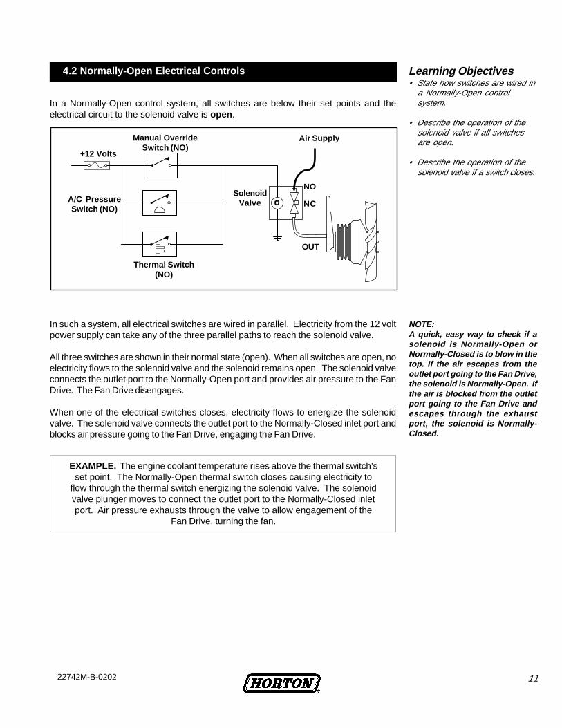
In a Normally-Open control system, all switches are below their set points and theelectrical circuit to the solenoid valve is open .
In such a system, all electrical switches are wired in parallel. Electricity from the 12 voltpower supply can take any of the three parallel paths to reach the solenoid valve.
All three switches are shown in their normal state (open). When all switches are open, noelectricity flows to the solenoid valve and the solenoid remains open. The solenoid valveconnects the outlet port to the Normally-Open port and provides air pressure to the FanDrive. The Fan Drive disengages.
When one of the electrical switches closes, electricity flows to energize the solenoidvalve. The solenoid valve connects the outlet port to the Normally-Closed inlet port andblocks air pressure going to the Fan Drive, engaging the Fan Drive.
EXAMPLE. The engine coolant temperature rises above the thermal switch’sset point. The Normally-Open thermal switch closes causing electricity to
flow through the thermal switch energizing the solenoid valve. The solenoidvalve plunger moves to connect the outlet port to the Normally-Closed inletport. Air pressure exhausts through the valve to allow engagement of the
Fan Drive, turning the fan.
NOTE:A quick, easy way to check if asolenoid is Normally-Open orNormally-Closed is to blow in thetop. If the air escapes from theoutlet port going to the Fan Drive,the solenoid is Normally-Open. Ifthe air is blocked from the outletport going to the Fan Drive andescapes through the exhaustport, the solenoid is Normally-Closed.
Learning Objectives• State how switches are wired in
a Normally-Open controlsystem.
• Describe the operation of thesolenoid valve if all switchesare open.
• Describe the operation of thesolenoid valve if a switch closes.
4.2 Normally-Open Electrical Controls
NC
NOSolenoid
Valve
Thermal Switch(NO)
A/C PressureSwitch (NO)
Manual OverrideSwitch (NO)
+12 Volts
OUT
Air Supply
12 22742M-B-0202
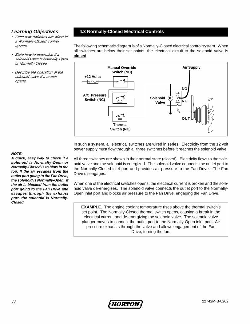
The following schematic diagram is of a Normally-Closed electrical control system. Whenall switches are below their set points, the electrical circuit to the solenoid valve isclosed .
In such a system, all electrical switches are wired in series. Electricity from the 12 voltpower supply must flow through all three switches before it reaches the solenoid valve.
All three switches are shown in their normal state (closed). Electricity flows to the sole-noid valve and the solenoid is energized. The solenoid valve connects the outlet port tothe Normally-Closed inlet port and provides air pressure to the Fan Drive. The FanDrive disengages.
When one of the electrical switches opens, the electrical current is broken and the sole-noid valve de-energizes. The solenoid valve connects the outlet port to the Normally-Open inlet port and blocks air pressure to the Fan Drive, engaging the Fan Drive.
EXAMPLE. The engine coolant temperature rises above the thermal switch’sset point. The Normally-Closed thermal switch opens, causing a break in theelectrical current and de-energizing the solenoid valve. The solenoid valve
plunger moves to connect the outlet port to the Normally-Open inlet port. Airpressure exhausts through the valve and allows engagement of the Fan
Drive, turning the fan.
NOTE:A quick, easy way to check if asolenoid is Normally-Open orNormally-Closed is to blow in thetop. If the air escapes from theoutlet port going to the Fan Drive,the solenoid is Normally-Open. Ifthe air is blocked from the outletport going to the Fan Drive andescapes through the exhaustport, the solenoid is Normally-Closed.
Learning Objectives• State how switches are wired in
a Normally-Closed controlsystem.
• State how to determine if asolenoid valve is Normally-Openor Normally-Closed.
• Describe the operation of thesolenoid valve if a switchopens.
4.3 Normally-Closed Electrical Controls
ThermalSwitch (NC)
SolenoidValve NC
OUT
NO
+12 Volts
Manual OverrideSwitch (NC)
A/C PressureSwitch (NC)
Air Supply

1322742M-B-0202
• Electrical switches are wired inparallel.
• Air supply plumbed to solenoid’sNormally-Open port (the end port).
• Test Fan Drive by installing a jumperwire across a sensor.
• Manual Override Switch(if equipped).
Normally-Open Electrical System with Normally-Open Solenoid Valve
• Electrical switches are wired inseries.
• Air supply plumbed to solenoid’sNormally-Closed port (the sideport).
• Test Fan Drive by disconnecting awire from a sensor.
• Manual Override Switch(if equipped).
All switches openSolenoid de-energized
Drive disengaged
Any switch closedSolenoid energized
Drive engaged
Normally-Closed Electrical System with Normally-Closed Solenoid Valve
All switches closedSolenoid energizedDrive disengaged
Any switch openSolenoid de-energized
Drive engaged
Normally-OpenElectrical System
Normally-ClosedElectrical System
Air Supply in
To Fan DriveExhaust
Normally-Open Port Air Supply in
To FanDrive
Exhaust
Normally-Closed Port
Learning Objectives• For each type of control system
determine: 1) the proper port toplumb the solenoid valve, and2) the proper method to test theFan Drive.
4.4 Comparison - Open/Closed Electrical Controls
4.5 Summary - Open/Closed Electrical Controls Learning Objectives• (Review Only)

14 22742M-B-0202
1. Locate the DriveMaster Fan Drive and list the model.
2. Locate the solenoid valve.
3. Locate the Fan Drive air filter (if equipped).
4. Locate the coolant temperature switch or sensor.
5. Locate the air-conditioning refrigerant pressure switch (if equipped).
6. Locate the Fan Drive manual override switch (if equipped).
7. How many belts are on the Fan Drive sheave?
8. What engine components do the belts go around?
9. How many bolts mount the fan drive to the engine?
10. Locate the air hose that supplies air to the solenoid.Where does the hose attach to the air supply?
11. Does the truck have an ECM?
12. In the truck’s service manual, locate the electrical diagram for the fandrive control solenoid and the ECM.
13. Draw the schematic symbol used in your truck’s electrical diagram foreach of the following components:
Solenoid valve
Engine-coolant thermal switch/sensor
Air-conditioning refrigerant pressure switch/sensor
Manual override switch
LAB ACTIVITY - FAN DRIVE CONTROL COMPONENTS
Locate a truck with a Horton DriveMaster Fan Drive, preferably a make and model youwould work on.
For your safety, be sure the en-gine is off.
Locate the components listed below and answer the questions by filling in the corre-sponding blanks and checking the box next to the number when you complete a step.Upon completion, please check this activity with an instructor or supervisor.
Learning Objective• Locate and identify components
of the Fan Drive system.
• Interpret the vehicle's electricaldiagram for various Fan Drivesystem components.
1522742M-B-0202
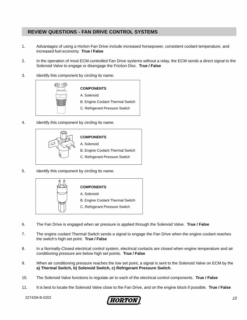
4. Identify this component by circling its name.
5. Identify this component by circling its name.
6. The Fan Drive is engaged when air pressure is applied through the Solenoid Valve. True / False
7. The engine coolant Thermal Switch sends a signal to engage the Fan Drive when the engine coolant reachesthe switch’s high set point. True / False
8. In a Normally-Closed electrical control system, electrical contacts are closed when engine temperature and airconditioning pressure are below high set points. True / False
9. When air conditioning pressure reaches the low set point, a signal is sent to the Solenoid Valve on ECM by thea) Thermal Switch, b) Solenoid Switch, c) Refrigerant Pressure Switch .
10. The Solenoid Valve functions to regulate air to each of the electrical control components. True / False
11. It is best to locate the Solenoid Valve close to the Fan Drive, and on the engine block if possible. True / False
REVIEW QUESTIONS - FAN DRIVE CONTROL SYSTEMS
1. Advantages of using a Horton Fan Drive include increased horsepower, consistent coolant temperature, andincreased fuel economy. True / False
2. In the operation of most ECM-controlled Fan Drive systems without a relay, the ECM sends a direct signal to theSolenoid Valve to engage or disengage the Friction Disc. True / False
3. Identify this component by circling its name.
COMPONENTS
A. Solenoid
B. Engine Coolant Thermal Switch
C. Refrigerant Pressure Switch
COMPONENTS
A. Solenoid
B. Engine Coolant Thermal Switch
C. Refrigerant Pressure Switch
COMPONENTS
A. Solenoid
B. Engine Coolant Thermal Switch
C. Refrigerant Pressure Switch
16 22742M-B-0202
12. An Electronic Control Module is: a) a computer, b) a sensor, c) a sending unit
13. ECM control systems improve engine performance, reliability and fuel efficiency more than non-ECM controlsystems. True / False
14. ECMs monitor data from sensors and send the appropriate signals to controls and actuators based on:a) operator options, b) programming logic, c) vehicle service periods .
15. In most ECM-controlled systems, sensors and actuators are wired directly to the ECM, not the Solenoid Valve.True / False
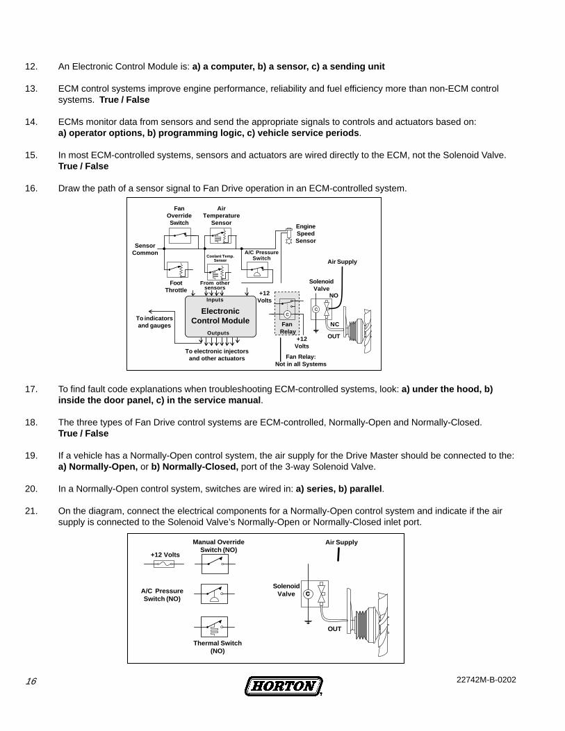
16. Draw the path of a sensor signal to Fan Drive operation in an ECM-controlled system.
17. To find fault code explanations when troubleshooting ECM-controlled systems, look: a) under the hood, b)inside the door panel, c) in the service manual .
18. The three types of Fan Drive control systems are ECM-controlled, Normally-Open and Normally-Closed.True / False
19. If a vehicle has a Normally-Open control system, the air supply for the Drive Master should be connected to the:a) Normally-Open, or b) Normally-Closed, port of the 3-way Solenoid Valve.
20. In a Normally-Open control system, switches are wired in: a) series, b) parallel .
21. On the diagram, connect the electrical components for a Normally-Open control system and indicate if the airsupply is connected to the Solenoid Valve’s Normally-Open or Normally-Closed inlet port.
Fan Relay:Not in all Systems
FanOverrideSwitch
SensorCommon
FootThrottle
To indicatorsand gauges
Coolant Temp.Sensor
From othersensors
Inputs
ElectronicControl Module
Outputs
To electronic injectorsand other actuators
AirTemperature
Sensor
A/C PressureSwitch
EngineSpeedSensor
Air Supply
SolenoidValve
FanRelay
+12Volts
NO
NC
OUT
+12Volts
SolenoidValve
Thermal Switch(NO)
A/C PressureSwitch (NO)
Manual OverrideSwitch (NO)
+12 Volts
Air Supply
OUT
1722742M-B-0202
22. When all switches are open In a Normally-Open control system, the solenoid is: a) energized, b) de-energized,and the Fan Drive is: a) engaged, b) disengaged .
23. If a switch closes in a Normally-Open control system, the solenoid is: a) energized, b) de-energized, and theFan Drive is: a) engaged, b) disengaged .
24. In a Normally-Closed control system, switches are wired in parallel. True / False
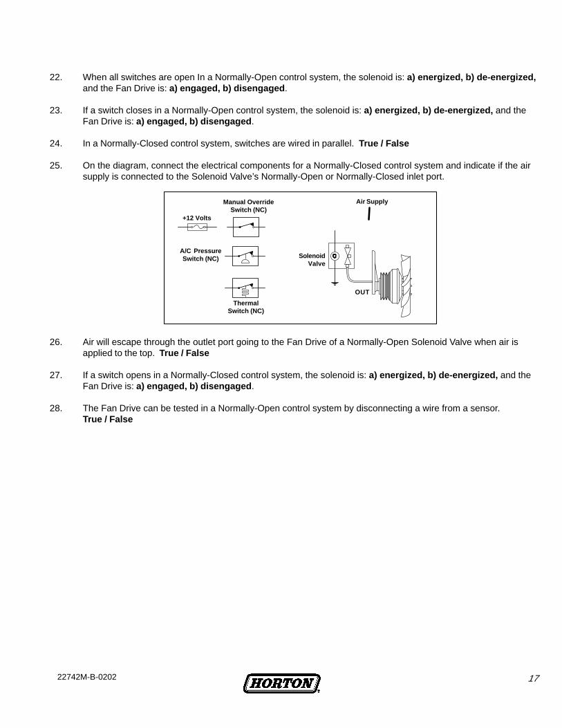
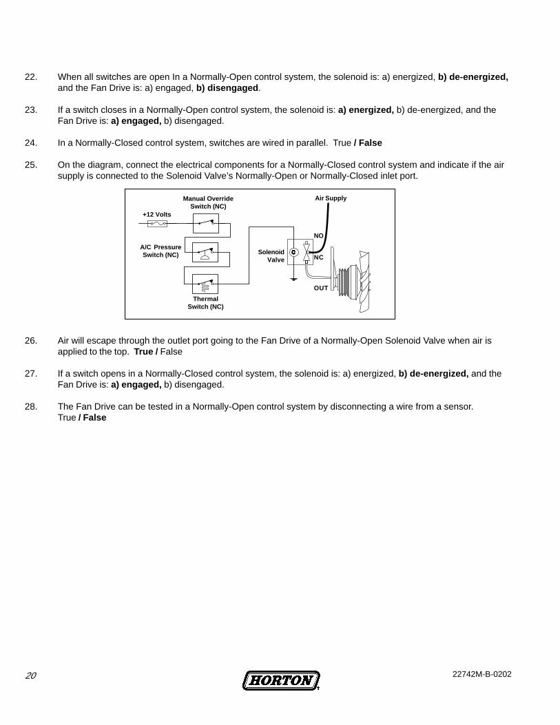
25. On the diagram, connect the electrical components for a Normally-Closed control system and indicate if the airsupply is connected to the Solenoid Valve’s Normally-Open or Normally-Closed inlet port.
26. Air will escape through the outlet port going to the Fan Drive of a Normally-Open Solenoid Valve when air isapplied to the top. True / False
27. If a switch opens in a Normally-Closed control system, the solenoid is: a) energized, b) de-energized, and theFan Drive is: a) engaged, b) disengaged .
28. The Fan Drive can be tested in a Normally-Open control system by disconnecting a wire from a sensor.True / False
ThermalSwitch (NC)
SolenoidValve
+12 Volts
Manual OverrideSwitch (NC)
A/C PressureSwitch (NC)
Air Supply
OUT

18 22742M-B-0202
Review Answers - Fan Drive Control Systems
1. Advantages of using a Horton Fan Drive include increased horsepower, consistent coolant temperature, andincreased fuel economy. True / False
2. In the operation of most ECM-controlled Fan Drive systems without a relay, the ECM sends a direct signal to theSolenoid Valve to engage or disengage the Friction Disc. True / False
3. Identify this component by circling its name.
4. Identify this component by circling its name.
5. Identify this component by circling its name.
6. The Fan Drive is engaged when air pressure is applied through the Solenoid Valve. True / False
7. The engine coolant Thermal Switch sends a signal to engage the Fan Drive when the engine coolant reachesthe switch’s high set point. True / False
8. In a Normally-Closed electrical control system, electrical contacts are closed when engine temperature and airconditioning pressure are below high set points. True / False
9. When air conditioning pressure reaches the low set point, a signal is sent to the Solenoid Valve on ECM by thea) Thermal Switch, b) Solenoid Switch, c) Refrigerant Pressure Switch .
10. The Solenoid Valve functions to regulate air to each of the electrical control components. True / False
11. It is best to locate the Solenoid Valve close to the Fan Drive, and on the engine block if possible. True / False
COMPONENTS
A. Solenoid
B. Engine Coolant Thermal Switch
C. Refrigerant Pressure Switch
COMPONENTS
A. Solenoid
B. Engine Coolant Thermal Switch
C. Refrigerant Pressure Switch
COMPONENTS
A. Solenoid
B. Engine Coolant Thermal Switch
C. Refrigerant Pressure Switch

1922742M-B-0202
12. An Electronic Control Module is: a) a computer, b) a sensor, c) a sending unit
13. ECM control systems improve engine performance, reliability and fuel efficiency more than non-ECM controlsystems. True / False
14. ECMs monitor data from sensors and send the appropriate signals to controls and actuators based on:a) operator options, b) programming logic, c) vehicle service periods.
15. In most ECM-controlled systems, sensors and actuators are wired directly to the ECM, not the Solenoid Valve.True / False
16. Draw the correct path of a sensor signal to Fan Drive operation in an ECM-controlled system.
17. To find fault code explanations when troubleshooting ECM-controlled systems, look: a) under the hood,b) inside the door panel, c) in the service manual .
18. The three types of Fan Drive control systems are ECM-controlled, Normally-Open and Normally-Closed.True / False
19. If a vehicle has a Normally-Open control system, the air supply for the Drive Master should be connected to the:a) Normally-Open, or b) Normally-Closed, port of the 3-way Solenoid Valve.
20. In a Normally-Open control system, switches are wired in: a) series, b) parallel .
21. On the diagram, connect the electrical components for a Normally-Open control system and indicate if the airsupply is connected to the Solenoid Valve’s Normally-Open or Normally-Closed inlet port.
Fan Relay:Not in all Systems
FanOverrideSwitch
SensorCommon
FootThrottle
To indicatorsand gauges
Coolant Temp.Sensor
From othersensors
Inputs
ElectronicControl Module
Outputs
To electronic injectorsand other actuators
AirTemperature
Sensor
A/C PressureSwitch
EngineSpeedSensor
Air Supply
SolenoidValve
FanRelay
+12Volts
NO
NC
OUT
+12Volts
NC
NOSolenoid
Valve
Thermal Switch(NO)
A/C PressureSwitch (NO)
Manual OverrideSwitch (NO)
+12 Volts
OUT
Air Supply
20 22742M-B-0202
22. When all switches are open In a Normally-Open control system, the solenoid is: a) energized, b) de-energized,and the Fan Drive is: a) engaged, b) disengaged .
23. If a switch closes in a Normally-Open control system, the solenoid is: a) energized, b) de-energized, and theFan Drive is: a) engaged, b) disengaged.
24. In a Normally-Closed control system, switches are wired in parallel. True / False
25. On the diagram, connect the electrical components for a Normally-Closed control system and indicate if the airsupply is connected to the Solenoid Valve’s Normally-Open or Normally-Closed inlet port.
26. Air will escape through the outlet port going to the Fan Drive of a Normally-Open Solenoid Valve when air isapplied to the top. True / False
27. If a switch opens in a Normally-Closed control system, the solenoid is: a) energized, b) de-energized, and theFan Drive is: a) engaged, b) disengaged.
28. The Fan Drive can be tested in a Normally-Open control system by disconnecting a wire from a sensor.True / False
ThermalSwitch (NC)
SolenoidValve NC
OUT
NO
+12 Volts
Manual OverrideSwitch (NC)
A/C PressureSwitch (NC)
Air Supply

2122742M-B-0202
You must follow your company safety practices, which should adhere to or be better thanFederal or State approved shop safety practices and procedures. Be sure that you read andunderstand all the procedures and instructions before beginning work on this unit.
NOTEParts replacement and/or repair of your Horton DRIVE MASTER Fan Drive shouldbe performed only by the Horton Factory or an authorized Horton Distributor or
Dealer to keep your warranty coverage intact during the warranty period.
Before rebuilding your DRIVEMASTER Fan Drive, note the Fan Drive Serial No., ServicePart No., Date of Installation, and Vehicle Mileage.
Serial No.
Service Part No.
Installation Date
Vehicle Mileage
Part Numberand Serial Number
PRIOR TO SERVICING
22 22742M-B-0202
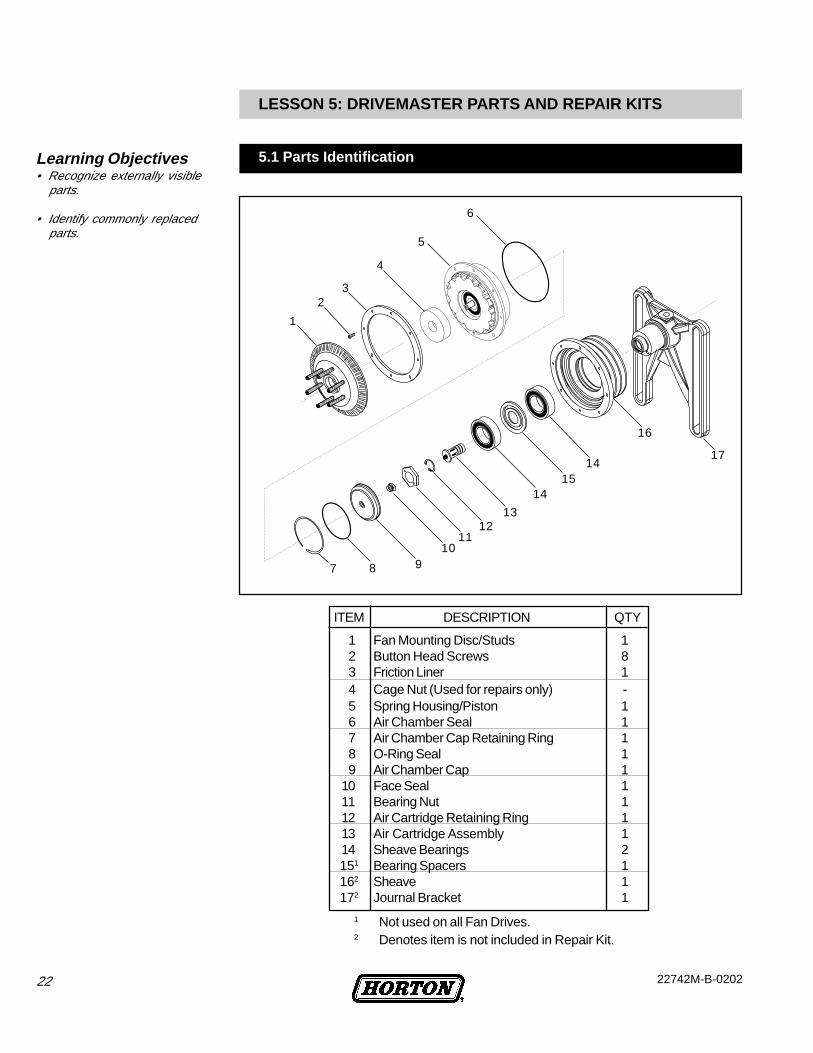
1 Fan Mounting Disc/Studs 12 Button Head Screws 83 Friction Liner 14 Cage Nut (Used for repairs only) -5 Spring Housing/Piston 16 Air Chamber Seal 17 Air Chamber Cap Retaining Ring 18 O-Ring Seal 19 Air Chamber Cap 1
10 Face Seal 111 Bearing Nut 112 Air Cartridge Retaining Ring 113 Air Cartridge Assembly 114 Sheave Bearings 2
151 Bearing Spacers 1 162 Sheave 1 172 Journal Bracket 1
LESSON 5: DRIVEMASTER PARTS AND REPAIR KITS
1
23
4
5
6
7 8 910
1112
13
1415
14
16
17
1 Not used on all Fan Drives.2 Denotes item is not included in Repair Kit.
ITEM DESCRIPTION QTY
5.1 Parts IdentificationLearning Objectives• Recognize externally visible
parts.
• Identify commonly replacedparts.

2322742M-B-0202
5.2 Repair Kits
Horton offers several different ways to repair or rebuild your DriveMaster Fan Drive.
Button Head Screws (#2): Used to attach the Friction Liner and the Spring Housing/Piston Assembly to the Sheave.Cage Nut (#4): Used to keep the Spring Housing/Piston Assembly together when removingfrom the Sheave. It maintains pressure on internal springs after the Button Head Screwsare removed.Air Chamber Seal (#6): Forms an air seal between the Air Chamber and the Spring Housing/Piston Assembly. It is positioned around the bottom half of the Spring Housing/PistonAssembly.Retaining Rings (#7, #12): There are two Retaining Rings in the Seal Kit. The smallerRetaining Ring is used to hold the air cartridge inside the Journal Bracket shaft. Wheninstalling this Retaining ring, the beveled side must be facing the air Cartridge. The largerRetaining Ring is used to hold the Air Chamber Cap in place.O-Ring (#8): Forms an air seal between the Air Chamber and the Air Chamber Cap.Face Seal (#10): Screws into the center of the Air Chamber Cap, forming an air seal with thecarbon tip of the Air Cartridge.Air Cartridge (#13): Fits inside the Journal Bracket shaft. Air pressure comes up throughthe center of the shaft, into and through the Air Cartridge, and into the Air Chamber. The AirCartridge has a spring loaded carbon tip that presses against the Face Seal, forming an airtight seal while the Fan Drive is spinning.T55 Torx Plus Bit (not pictured): Used to remove the Fan Mounting Disc from the JackBolt.O-Ring Lubricant (not pictured): Apply lubricant to the new Air Chamber Cap O-Ring Sealand the Air Chamber Seal before installation.
Install a Seal Kit if an air leak has developed inside of the DriveMaster Fan Drive. The SealKit consists of the parts listed and described below:
1. DriveMaster Seal Kit (Part #994346) Learning Objectives• Describe when a Seal Kit would
be used.
24 22742M-B-0202
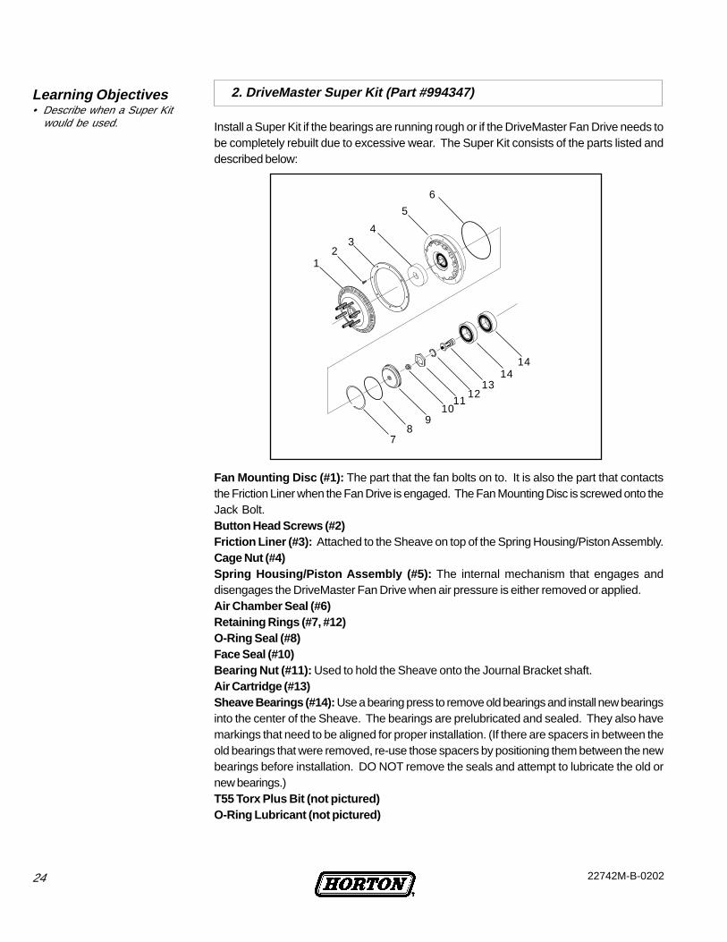
Install a Super Kit if the bearings are running rough or if the DriveMaster Fan Drive needs tobe completely rebuilt due to excessive wear. The Super Kit consists of the parts listed anddescribed below:
Fan Mounting Disc (#1): The part that the fan bolts on to. It is also the part that contactsthe Friction Liner when the Fan Drive is engaged. The Fan Mounting Disc is screwed onto theJack Bolt.Button Head Screws (#2)Friction Liner (#3): Attached to the Sheave on top of the Spring Housing/Piston Assembly.Cage Nut (#4)Spring Housing/Piston Assembly (#5): The internal mechanism that engages anddisengages the DriveMaster Fan Drive when air pressure is either removed or applied.Air Chamber Seal (#6)Retaining Rings (#7, #12)O-Ring Seal (#8)Face Seal (#10)Bearing Nut (#11): Used to hold the Sheave onto the Journal Bracket shaft.Air Cartridge (#13)Sheave Bearings (#14): Use a bearing press to remove old bearings and install new bearingsinto the center of the Sheave. The bearings are prelubricated and sealed. They also havemarkings that need to be aligned for proper installation. (If there are spacers in between theold bearings that were removed, re-use those spacers by positioning them between the newbearings before installation. DO NOT remove the seals and attempt to lubricate the old ornew bearings.)T55 Torx Plus Bit (not pictured)O-Ring Lubricant (not pictured)
2. DriveMaster Super Kit (Part #994347)Learning Objectives• Describe when a Super Kit
would be used.
12
34
5
6
78
910
1112
1314
14
2522742M-B-0202
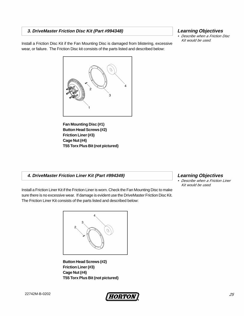
Install a Friction Disc Kit if the Fan Mounting Disc is damaged from blistering, excessivewear, or failure. The Friction Disc kit consists of the parts listed and described below:
Fan Mounting Disc (#1)Button Head Screws (#2)Friction Liner (#3)Cage Nut (#4)T55 Torx Plus Bit (not pictured)
Install a Friction Liner Kit if the Friction Liner is worn. Check the Fan Mounting Disc to makesure there is no excessive wear. If damage is evident use the DriveMaster Friction Disc Kit.The Friction Liner Kit consists of the parts listed and described below:
Button Head Screws (#2)Friction Liner (#3)Cage Nut (#4)T55 Torx Plus Bit (not pictured)
3. DriveMaster Friction Disc Kit (Part #994348)
4. DriveMaster Friction Liner Kit (Part #994349)
Learning Objectives• Describe when a Friction Disc
Kit would be used.
Learning Objectives• Describe when a Friction Liner
Kit would be used.
26 22742M-B-0202
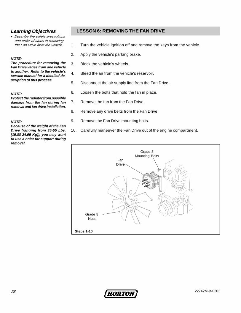
LESSON 6: REMOVING THE FAN DRIVE
1. Turn the vehicle ignition off and remove the keys from the vehicle.
2. Apply the vehicle's parking brake.
3. Block the vehicle's wheels.
4. Bleed the air from the vehicle’s reservoir.
5. Disconnect the air supply line from the Fan Drive.
6. Loosen the bolts that hold the fan in place.
7. Remove the fan from the Fan Drive.
8. Remove any drive belts from the Fan Drive.
9. Remove the Fan Drive mounting bolts.
10. Carefully maneuver the Fan Drive out of the engine compartment.
Learning Objectives• Describe the safety precautions
and order of steps in removingthe Fan Drive from the vehicle.
NOTE:Protect the radiator from possibledamage from the fan during fanremoval and fan drive installation.
NOTE:The procedure for removing theFan Drive varies from one vehicleto another. Refer to the vehicle’sservice manual for a detailed de-scription of this process.
NOTE:Because of the weight of the FanDrive (ranging from 35-55 Lbs.[15.88-24.95 Kg]), you may wantto use a hoist for support duringremoval.
Steps 1-10
FanDrive
Grade 8Mounting Bolts
Grade 8Nuts
2722742M-B-0202
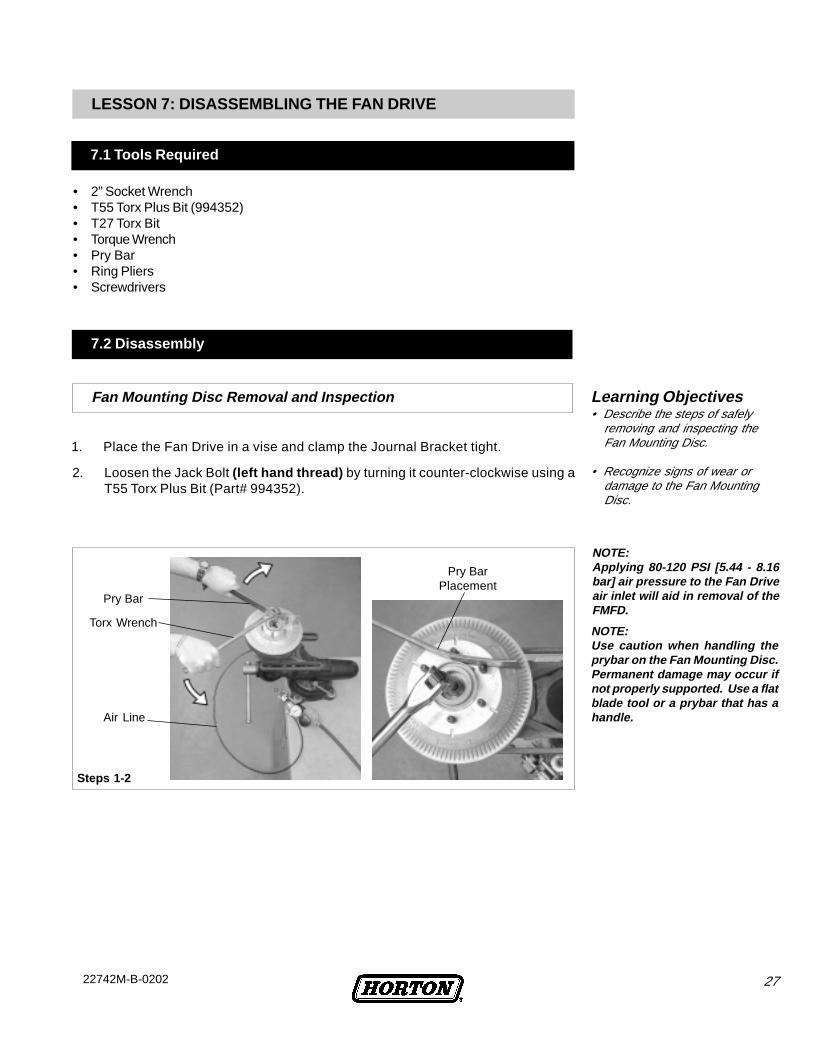
1. Place the Fan Drive in a vise and clamp the Journal Bracket tight.
NOTE:Applying 80-120 PSI [5.44 - 8.16bar] air pressure to the Fan Driveair inlet will aid in removal of theFMFD.
2. Loosen the Jack Bolt (left hand thread) by turning it counter-clockwise using aT55 Torx Plus Bit (Part# 994352).
Steps 1-2
Pry Bar
NOTE:Use caution when handling theprybar on the Fan Mounting Disc.Permanent damage may occur ifnot properly supported. Use a flatblade tool or a prybar that has ahandle.
Torx Wrench
Air Line
Pry BarPlacement
LESSON 7: DISASSEMBLING THE FAN DRIVE
• 2” Socket Wrench• T55 Torx Plus Bit (994352)• T27 Torx Bit• Torque Wrench• Pry Bar• Ring Pliers• Screwdrivers
7.1 Tools Required
Fan Mounting Disc Removal and Inspection
7.2 Disassembly
Learning Objectives• Describe the steps of safely
removing and inspecting theFan Mounting Disc.
• Recognize signs of wear ordamage to the Fan MountingDisc.
28 22742M-B-0202
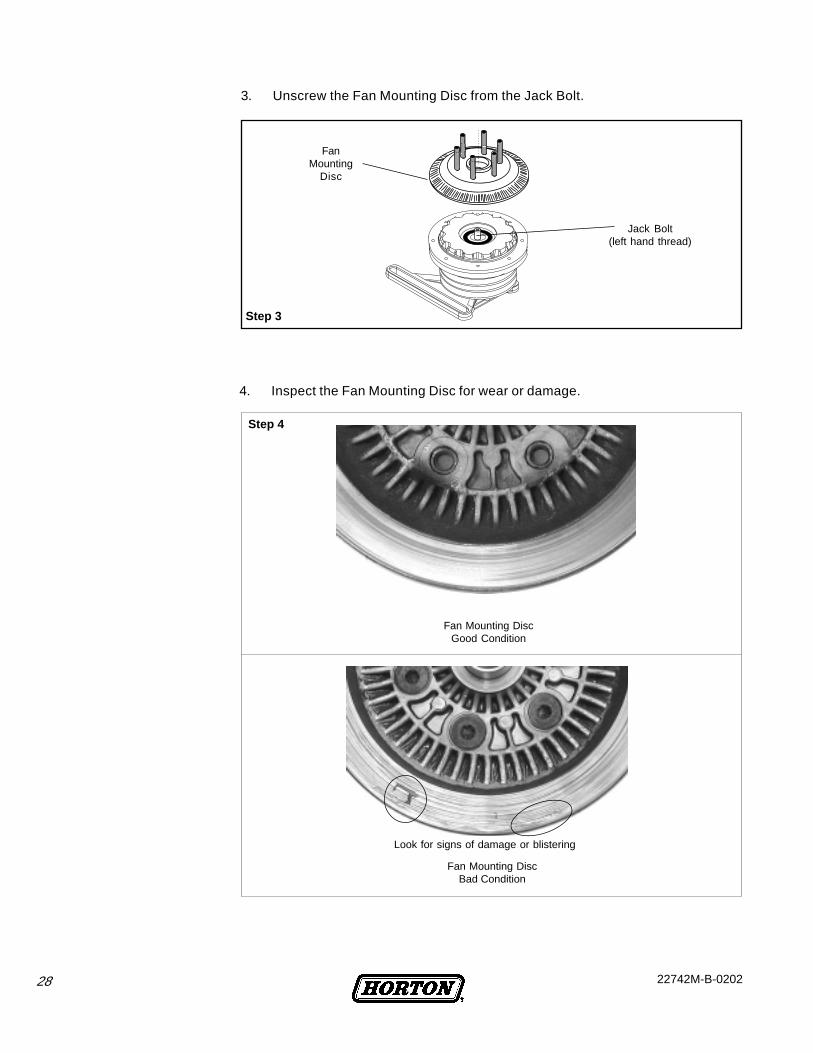
FanMounting
Disc
Jack Bolt(left hand thread)
3. Unscrew the Fan Mounting Disc from the Jack Bolt.
Fan Mounting DiscGood Condition
Fan Mounting DiscBad Condition
Step 3
Look for signs of damage or blistering
4. Inspect the Fan Mounting Disc for wear or damage.
Step 4
2922742M-B-0202
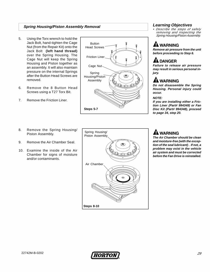
8. Remove the Spring Housing/Piston Assembly.
9. Remove the Air Chamber Seal.
10. Examine the inside of the AirChamber for signs of moistureand/or contaminants.
The Air Chamber should be cleanand moisture-free (with the excep-tion of the seal lubricant) . If not, aproblem may exist in the vehicleair system and must be correctedbefore the Fan Drive is reinstalled.
Steps 8-10
Spring Housing/Piston Assembly
Air Chamber
5. Using the Torx wrench to hold theJack Bolt, hand-tighten the CageNut (from the Repair Kit) onto theJack Bolt (left hand thread)over the Spring Housing. TheCage Nut will keep the SpringHousing and Piston together asan assembly. It will also maintainpressure on the internal Springsafter the Button Head Screws areremoved.
Remove air pressure from the unitbefore proceeding to Step 6.
Do not disassemble the SpringHousing. Personal injury couldoccur.
6. Remove the 8 Button HeadScrews using a T27 Torx Bit.
7. Remove the Friction Liner.
Steps 5-7
ButtonHead Screws
Cage Nut
Friction Liner
SpringHousing/Piston
Assembly
NOTE:If you are installing either a Fric-tion Liner (Part# 994349) or FanDisc Kit (Part# 994348), proceedto page 34, step 20.
Failure to release air pressuremay result in serious personal in-jury.
Spring Housing/Piston Assembly Removal Learning Objectives• Describe the steps of safely
removing and inspecting theSpring Housing/Piston Assembly.

30 22742M-B-0202
Wear eye safety protection whenremoving Retaining Ring to avoidserious injury.
If dirt or oil exists in the air sys-tem, the air system must becleaned and dried before the FanDrive is reinstalled.
NOTE:If you are only installing a Seal Kit(Part #994346), proceed to page31, step 20
11. Remove the Air Chamber Cap RetainingRing.
12. Gently and evenly pry the Air ChamberCap out of the Sheave using two smallscrewdrivers placed 180° apart.
13. Remove the O-Ring Seal from the AirChamber Cap.
14. Remove the Face Seal.
15. Inspect the Face Seal for signs of wear.Wear indicates that dirt may exist inthe air system.
16. Remove the Bearing Nut from theJournal Bracket using a 2” SocketWrench.
17. Remove the Sheave from the JournalBracket.
Air Chamber Seals
Sheave and Sheave Bearings
Bearing Nut
Step 16
Journal Bracket
Sheave
Journal Bracket
Step 17
Air ChamberCap
Steps 11-15
Air ChamberSeal
Retaining Ring
Face Seal
O-Ring Seal
Learning Objectives• Describe the steps of removing
and inspecting the Air ChamberSeals.
Learning Objectives• Describe the steps of removing
the Sheave from the JournalBracket.
18. Fully support the Sheave andpress out the Bearings.
19. Fully clean and remove any dirt,debris, or corrosion that may bepresent.
SUPPORT
SUPPORT
Bearings
Step 18-19
PRESSTO
REMOVE

3122742M-B-0202
20. Remove the Retaining Ring.
21. Remove the Air Cartridge Assembly.
22. Clean the Journal Bracket bore ifnecessary.
Air Cartridge Removal
Wear eye safety protection whenremoving Retaining Ring to avoidserious injury.
Learning Objectives• Describe the steps of removing
the Air Cartridge.
LESSON 8: REBUILDING THE FAN DRIVE
8.1 Torque Specifications
Learning Objectives• Describe the steps of removing
and replacing the SheaveBearings.
TIGHTENING TORQUE80 In. Lbs.
[9 N•m]75-100 In. Lbs.[8.5-11.5 N•m]
130 Ft. Lbs.[176 N•m]
100 Ft. Lbs.[136 N•m]
ITEM
3
10
11
--
DESCRIPTION
Button Head Screws
Face Seal
Bearing Nut
Jack Bolt (left hand thread)
Sheave Bearing Replacement
8.2 Rebuilding
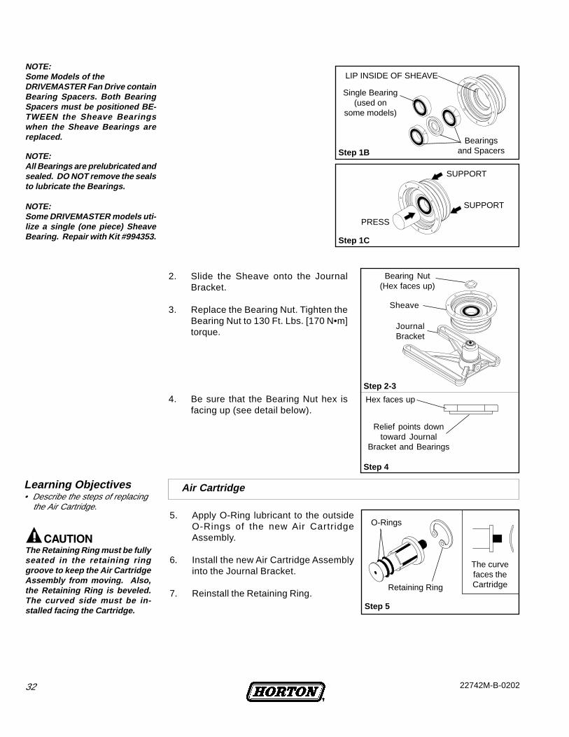
1. Fully supporting the Sheave,press the new Sheave Bearings(or single bearing) into place,noting the position of the lipinside the Sheave.See Figures 1A, 1B, 1C.
Align the chevron markings onthe bearings to form an arrow.The arrow may point in either
direction.
Step 1A
RetainingRing
Step 20
Step 21
Air CartridgeAssembly
Float Seal Tip
NOTEIf you are installing a Seal Kit(Part# 994346), proceed to page32, step 5.
32 22742M-B-0202
5. Apply O-Ring lubricant to the outsideO-Rings of the new Air CartridgeAssembly.
6. Install the new Air Cartridge Assemblyinto the Journal Bracket.
7. Reinstall the Retaining Ring.
2. Slide the Sheave onto the JournalBracket.
3. Replace the Bearing Nut. Tighten theBearing Nut to 130 Ft. Lbs. [170 N•m]torque.
4. Be sure that the Bearing Nut hex isfacing up (see detail below).
Step 5
Retaining Ring
O-Rings
The curvefaces theCartridge
Sheave
Bearing Nut(Hex faces up)
JournalBracket
Step 2-3
Step 4
Hex faces up
Relief points downtoward Journal
Bracket and Bearings
NOTE:Some DRIVEMASTER models uti-lize a single (one piece) SheaveBearing. Repair with Kit #994353.
NOTE:Some Models of theDRIVEMASTER Fan Drive containBearing Spacers. Both BearingSpacers must be positioned BE-TWEEN the Sheave Bearingswhen the Sheave Bearings arereplaced.
NOTE:All Bearings are prelubricated andsealed. DO NOT remove the sealsto lubricate the Bearings.
Step 1C
PRESS
SUPPORT
SUPPORT
Single Bearing(used on
some models)
Step 1B
LIP INSIDE OF SHEAVE
Bearingsand Spacers
Air Cartridge
The Retaining Ring must be fullyseated in the retaining ringgroove to keep the Air CartridgeAssembly from moving. Also,the Retaining Ring is beveled.The curved side must be in-stalled facing the Cartridge.
Learning Objectives• Describe the steps of replacing
the Air Cartridge.

3322742M-B-0202
Use extreme care when reas-sembling the Air Chamber com-ponents to avoid damage to theO-Ring and Air Chamber Seal.
Do not apply grease beyond Sealcontact surface as it will causeimproper Fan Drive function.
8. Using a clean/dry cloth, cleanboth the Float Seal Tip (see AirCartridge illustration, Step 4) ofthe Air Cartridge Assembly.
9. Also clean the Face Seal of theAir Chamber Cap.
10. Assemble the Air Chamber Capand Face Seal.
11. Lubricate the O-ring Seal withthe fresh lubricant supplied in thekit.
12. Install the O-ring Seal on the AirChamber Cap.
13. Carefully set the Air ChamberCap into the Sheave.
14. Install the Retaining Ring.
15. Install the Air Chamber Seal intothe Sheave.
16. Be sure the Seal is evenly seatedagainst the side and bottom ofthe groove surfaces.
17. Lubricate contact surfaces withthe fresh lubricant supplied in thekit.
18. Carefully set the new SpringHousing/Piston Assembly fromthe Repair Kit into position.
19. Gently rotate to al ign themounting holes in the assemblywith the Sheave.
NOTE:The new Face Seal is assembledwith an O-ring. If the old Face Sealdoes not have an O-ring, do notuse an O-ring with the new FaceSeal. Remove it from the newFace Seal and apply thread seal-ant (Loctite ® 511 or similar) to theFace Seal threads.
Air ChamberSeal
Spring Housing/Piston Assembly
Piston
Steps 18-19
“V” of Sealfaces downinto Sheave
Sheave
(cross
-secti
on)
Do not applygrease beyond
these areas.
Retaining Ring
Steps 13-14
Air ChamberCap
Sheave
Air Chamber SealDetail
Step 15-17
Seat Seal evenly againstside and bottom groove
surfaces.
Spring Housing/Piston Assembly Reassembly Learning Objectives• Describe the steps of safely
reinstalling the Spring Housing/Piston Assembly.
• State lubrication requirements andcautions when reassembling theSpring Housing/ Piston Assembly.
NOTE:The entire tube of O-Ring lubricantshould be used when lubricatingthe new seals and contact sur-faces of the Sheave and SpringHousing/Piston Assembly.
34 22742M-B-0202
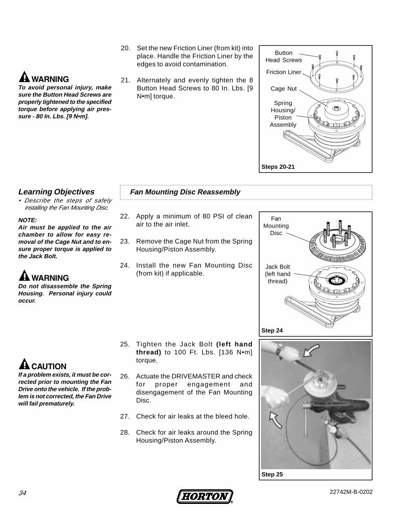
20. Set the new Friction Liner (from kit) intoplace. Handle the Friction Liner by theedges to avoid contamination.
21. Alternately and evenly tighten the 8Button Head Screws to 80 In. Lbs. [9N•m] torque.
NOTE:Air must be applied to the airchamber to allow for easy re-moval of the Cage Nut and to en-sure proper torque is applied tothe Jack Bolt.
If a problem exists, it must be cor-rected prior to mounting the FanDrive onto the vehicle. If the prob-lem is not corrected, the Fan Drivewill fail prematurely.
25. Tighten the Jack Bolt ( left handthread) to 100 Ft. Lbs. [136 N•m]torque.
26. Actuate the DRIVEMASTER and checkfor proper engagement anddisengagement of the Fan MountingDisc.
27. Check for air leaks at the bleed hole.
28. Check for air leaks around the SpringHousing/Piston Assembly.
23. Remove the Cage Nut from the SpringHousing/Piston Assembly.
24. Install the new Fan Mounting Disc(from kit) if applicable.
22. Apply a minimum of 80 PSI of cleanair to the air inlet.
To avoid personal injury, makesure the Button Head Screws areproperly tightened to the specifiedtorque before applying air pres-sure - 80 In. Lbs. [9 N•m].
Steps 20-21
ButtonHead Screws
Cage Nut
Friction Liner
SpringHousing/
PistonAssembly
Step 24
FanMounting
Disc
Jack Bolt(left handthread)
Step 25
Fan Mounting Disc ReassemblyLearning Objectives• Describe the steps of safely
installing the Fan Mounting Disc.
Do not disassemble the SpringHousing. Personal injury couldoccur.
3522742M-B-0202
LESSON 9: REINSTALLING THE FAN DRIVE Learning Objectives• Describe the steps of safely
reinstalling the Fan Drive.• Describe requirements for proper
belt tensioning.• Describe methods to check for
proper Fan Drive operation.
On the workbench, apply 90 PSI[6.21 bar] clean air pressure andcheck the Fan Drive for air leaks.
NOTE:Most engines have multiple mount-ing locations. Be sure to use thecorrect holes for the application.
Correct belt adjustment and align-ment is necessary for all belt drivencomponents to assure longevity ofcomponent life. Over tightening ofbelts will shorten bearing life. Loosebelts will cause excessive belt wearand shorten bearing life. Consultthe equipment manufacturer and/or engine manufacturer specifica-tions for proper belt adjustment.
NOTE:The maximum fan diameter is 32''.If a larger fan diameter is required,contact Horton at 1-800-621-1320.
11. Start the engine and let the air pressure build to at least 90 PSI [6.21 bar].
12. If the vehicle is fitted with a manual override switch, engage and disengagethe Fan Drive to observe for proper operation as well as air leaks.
13. Turn off the engine.
1. Turn the vehicle ignition off and remove the keys.
2. Apply the vehicle's parking brake.
3. Block the vehicle's wheels.
4. Prepare by cleaning all the mounting surfaces of dirt and debris.
5. Position the Drivemaster into place, aligning the mounting bracket.
6. Reinstall the mounting bolts and tighten to the vehicle manufacturer’sspecifications.
7. Replace and adjust the belts.
8. Check the condition of the fan. Look for cracks or missing weights.
9. Remount the fan on the Fan Drive and tighten the nuts to the vehiclemanufacturer’s specifications.
10. Reconnect the air supply line to the Drivemaster.
NOTE:Protect the radiator from possibledamage from the fan during fanremoval and fan drive installation.
NOTE:Use flat washers on eachmanufacturer’s approved bolt orstuds - DO NOT use lock washers.
NOTE:Remove all tools from the workarea and visually inspect the areain which you have been workingprior to starting the engine.
NOTE:For a Normally-Open electricalsystem, use a jumper across asensor. For a Normally-Closedelectrical system, open the circuitby disconnecting a sensor wire.
36 22742M-B-0202
Learning Objectives• Identify general conditions to look
for when observing Fan Driveoperation.
• Describe locations andmethods for checking for airleaks.
FilterElement
FilterBowl
BleedValve
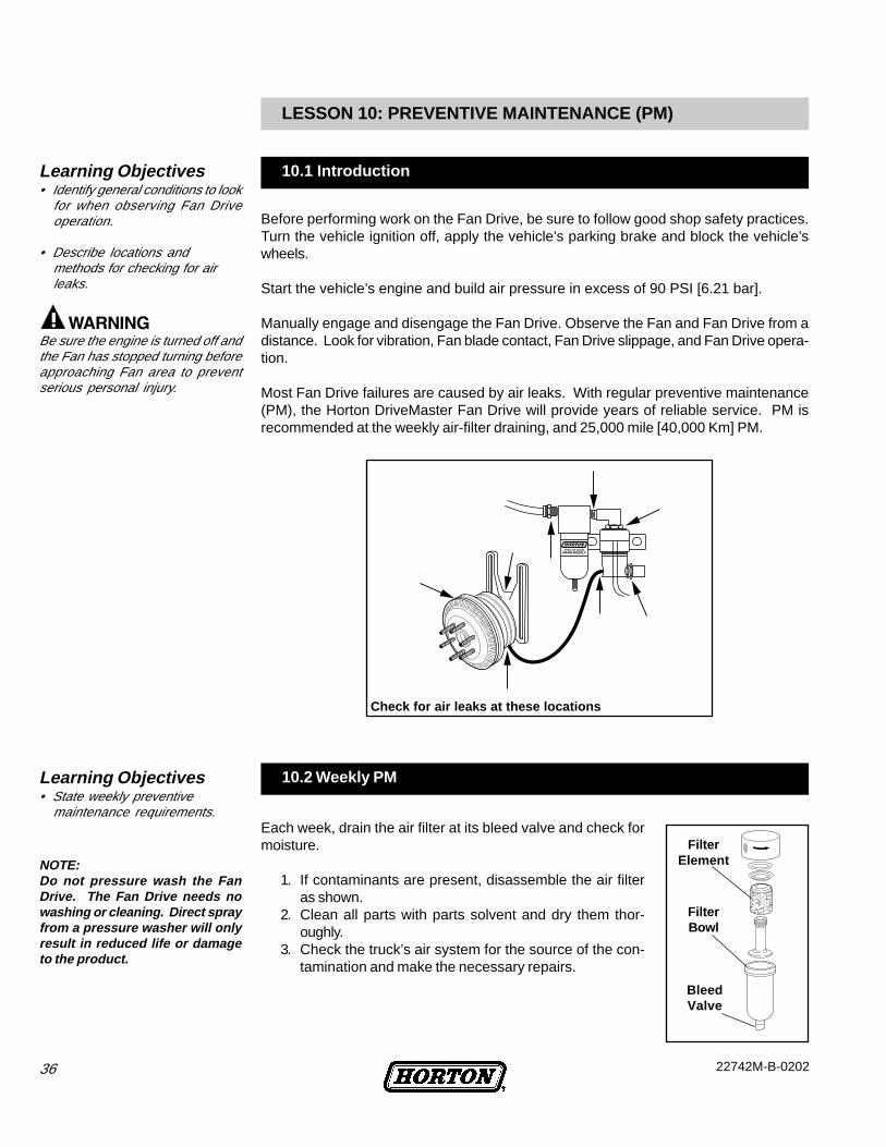
NOTE:Do not pressure wash the FanDrive. The Fan Drive needs nowashing or cleaning. Direct sprayfrom a pressure washer will onlyresult in reduced life or damageto the product.
Before performing work on the Fan Drive, be sure to follow good shop safety practices.Turn the vehicle ignition off, apply the vehicle’s parking brake and block the vehicle’swheels.
Start the vehicle’s engine and build air pressure in excess of 90 PSI [6.21 bar].
Manually engage and disengage the Fan Drive. Observe the Fan and Fan Drive from adistance. Look for vibration, Fan blade contact, Fan Drive slippage, and Fan Drive opera-tion.
Most Fan Drive failures are caused by air leaks. With regular preventive maintenance(PM), the Horton DriveMaster Fan Drive will provide years of reliable service. PM isrecommended at the weekly air-filter draining, and 25,000 mile [40,000 Km] PM.
LESSON 10: PREVENTIVE MAINTENANCE (PM)
10.1 Introduction
10.2 Weekly PM
Be sure the engine is turned off andthe Fan has stopped turning beforeapproaching Fan area to preventserious personal injury.
Learning Objectives• State weekly preventive
maintenance requirements.Each week, drain the air filter at its bleed valve and check formoisture.
1. If contaminants are present, disassemble the air filteras shown.
2. Clean all parts with parts solvent and dry them thor-oughly.
3. Check the truck’s air system for the source of the con-tamination and make the necessary repairs.
Check for air leaks at these locations
3722742M-B-0202
Check the Fan Drive bearings.1. Turn the Fan blade in both directions and feel for worn hub bearings.2. If the Fan belts can be easily removed, remove the belts and check for worn
sheave bearings.3. Turn the sheave in both directions-if either the hub or sheave bearings are worn,
remove and replace the Fan Drive.
Check the Fan Drive friction facing for wear by measuring the thickness of the frictionmaterial. A new facing is 7/16" [11.11 mm] thick. Replace the friction material if it hasworn to less than 3/16" [4.76 mm].
Check the electrical wiring at the thermal switch, air conditioning pressure switch, andsolenoid valve. Be certain there are not any loose wires or connections.
Check the Fan Drive for proper engagement and disengagement.Turn on the ignition switch but do not start the engine.
1. Be certain at least 90 PSI [6.21 bar] of air pressure is available in the truck’sreservoir.
2. To manually engage and disengage the Fan Drive, open and close the electricalcircuit going to the solenoid valve as follows:a.For a Normally-Open electrical system, use a jumper wire to
short out the thermal switch or the air-conditioning refrigerantpressure switch.
b.For a Normally-Closed electrical system, open the circuit bydisconnecting a wire from one of the sensors or from thesolenoid valve.
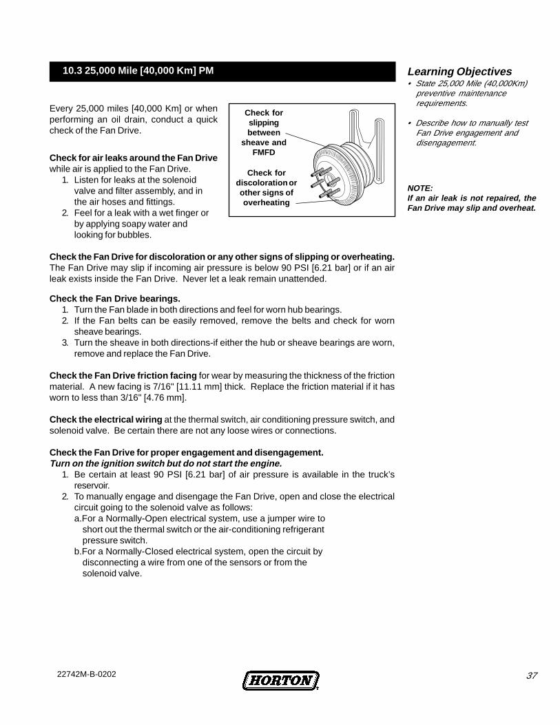
Check forslippingbetween
sheave andFMFD
Check for air leaks around the Fan Drivewhile air is applied to the Fan Drive.
1. Listen for leaks at the solenoidvalve and filter assembly, and inthe air hoses and fittings.
2. Feel for a leak with a wet finger orby applying soapy water andlooking for bubbles.
Check the Fan Drive for discoloration or any other signs of slipping or overheating.The Fan Drive may slip if incoming air pressure is below 90 PSI [6.21 bar] or if an airleak exists inside the Fan Drive. Never let a leak remain unattended.
Check fordiscoloration orother signs ofoverheating
Every 25,000 miles [40,000 Km] or whenperforming an oil drain, conduct a quickcheck of the Fan Drive.
Learning Objectives• State 25,000 Mile (40,000Km)
preventive maintenancerequirements.
• Describe how to manually testFan Drive engagement anddisengagement.
10.3 25,000 Mile [40,000 Km] PM
NOTE:If an air leak is not repaired, theFan Drive may slip and overheat.
38 22742M-B-0202
LESSON 11: TROUBLESHOOTING
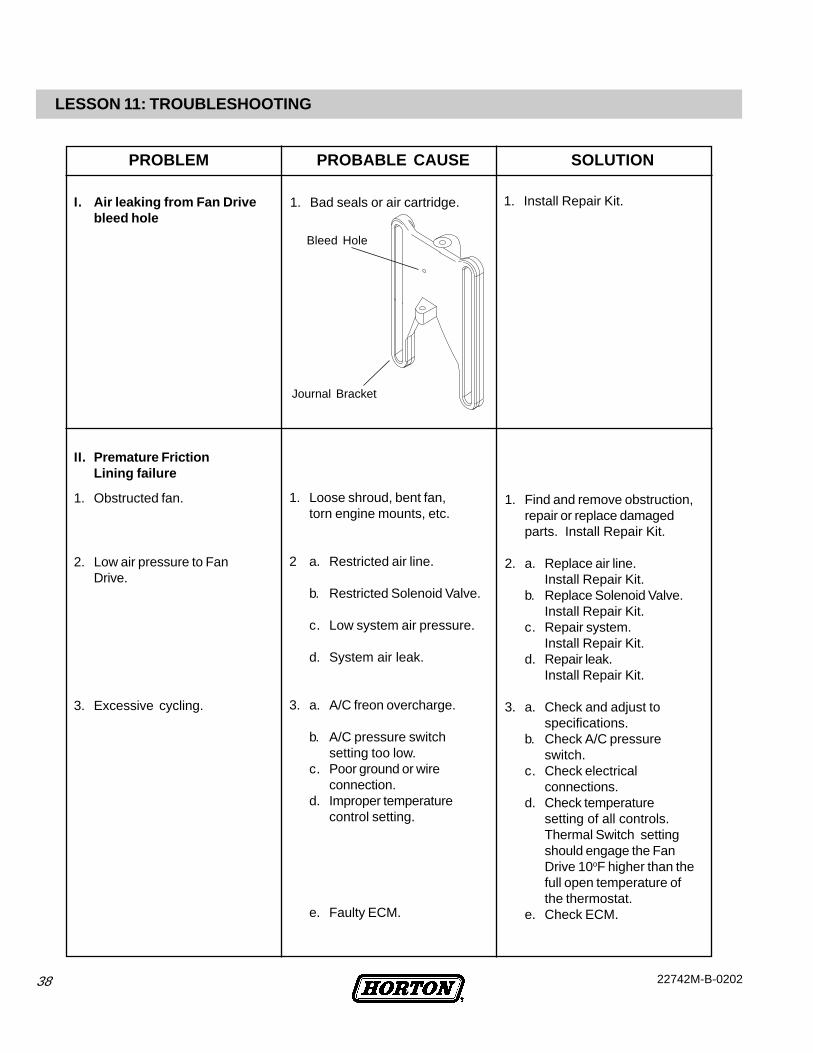
1. Bad seals or air cartridge.I. Air leaking from Fan Drivebleed hole
1. Install Repair Kit.
II. Premature FrictionLining failure
1. Obstructed fan.
2. Low air pressure to FanDrive.
3. Excessive cycling.
1. Find and remove obstruction,repair or replace damagedparts. Install Repair Kit.
2. a. Replace air line.Install Repair Kit.
b. Replace Solenoid Valve.Install Repair Kit.
c. Repair system.Install Repair Kit.
d. Repair leak.Install Repair Kit.
3. a. Check and adjust tospecifications.
b. Check A/C pressureswitch.
c. Check electricalconnections.
d. Check temperaturesetting of all controls.Thermal Switch settingshould engage the FanDrive 10oF higher than thefull open temperature ofthe thermostat.
e. Check ECM.
1. Loose shroud, bent fan,torn engine mounts, etc.
2 a. Restricted air line.
b. Restricted Solenoid Valve.
c. Low system air pressure.
d. System air leak.
3. a. A/C freon overcharge.
b. A/C pressure switchsetting too low.
c. Poor ground or wireconnection.
d. Improper temperaturecontrol setting.
e. Faulty ECM.
Journal Bracket
Bleed Hole
PROBLEM PROBABLE CAUSE SOLUTION
3922742M-B-0202
Piston will not actuate
1. Piston seized due tocontamination or dry seals.
1. Clean the air supply and installa Rebuild Kit.
f. Replace the ThermalSwitch.
g. Check for proper shutteroperation, winter front orother restriction in or infront of the radiator.
h. Replace the Air-TempSwitch.
f. Faulty Thermal Switch.
g. Restriction in front ofradiator blocking air flow.
h. Faulty Air-Temp Switch.
III. Fan Drive fails toengage/disengage Electrical Problem
1. Open/shorted circuit.
2. Improperly wired.
3. Thermal Switch incorrect forapplication.
4. Failed Solenoid Valve.
1. Check electrical connections.
2. Check wiring according todiagram.
3. Check Thermal Switchapplication. Replace if wrongor defective.
4. Replace the Solenoid Valve.
1. Check air line from solenoid toFan Drive for kinks orobstructions.
2. Replace the Solenoid Valve.Check to see if air exhaust isrestricted.
Air Problem
Air Problem
1. Solenoid Valve not exhaustingor engaging properly.
1. Check for plugged exhaust/intake port on the SolenoidValve. Clean or replace theSolenoid Valve.
II. Premature FrictionLining failureExcessive cycling (continued)
1. Air line restricted.
2. Solenoid Valve defective.
PROBLEM PROBABLE CAUSE SOLUTION
40 22742M-B-0202
IV. Fan Drive cyclesfrequently Electrical Problem
1. Poor ground wire connection.
2. Improper temperature controlsettings.
3. A/C Pressure Switch settingtoo low.
4. Restriction in front of radiator,blocking air flow.
5. Faulty Thermal Switch.
6. Faulty Air-Temp Switch.
7. Vehicle Coolant level too low.
1. Check electrical connections.
2. Check temperature setting ofall controls. Thermal Switchshould engage the Fan Drive 10o
F higher than the full opentemperature of the thermostat.
3. Check A/C Pressure Switch.Use higher switch.
4. Check shutter operation,winter fronts, or obstruction infront of radiator.
5. Replace the Thermal Switch.
6. Replace the Air-Temp Switch.
7. Fill to manufacturer'srecommended level.
V. Fan Drive engaged,engine running hot.
1. Restriction in front of radiator.
2. Fan capacity not large enough.
3. Problem in cooling system.
1. Make sure nothing isobstructing the air flow throughthe radiator.
2. Refer to specifications.
3. Refer to engine manual.
PROBLEM PROBABLE CAUSE SOLUTION
4122742M-B-0202
REVIEW QUESTIONS - FAN DRIVE SERVICE
1. DriveMaster Fan Drive parts that are visible externally are the Fan Mounting Disc, Friction Liner, Air ChamberSeal, and Journal Bracket. True / False
2. The two most commonly replaced parts are the Fan Mounting Disc and Friction Liner. True / False
3. A DriveMaster Seal Kit would be the most appropriate choice if: a) an air leak has developed inside the FanDrive, b) the Bearings are running rough or if the Fan Drive needs to be completely rebuilt, c) the FanMounting Disc is damaged, d) the Friction Liner is worn .
4. A DriveMaster Super Kit would be the most appropriate choice if: a) an air leak has developed inside the FanDrive, b) the Bearings are running rough or if the Fan Drive needs to be completely rebuilt, c) the FanMounting Disc is damaged, d) the Friction Liner is worn .
5. A DriveMaster Friction Disc Kit would be the most appropriate choice if: a) an air leak has developed inside theFan Drive, b) the Bearings are running rough or if the Fan Drive needs to be completely rebuilt, c) the FanMounting Disc is damaged, d) the Friction Liner is worn .
6. A DriveMaster Friction Liner Kit would be the most appropriate choice if: a) an air leak has developed insidethe Fan Drive, b) the Bearings are running rough or if the Fan Drive needs to be completely rebuilt, c) theFan Mounting Disc is damaged, d) the Friction Liner is worn .
7. Before removing the Fan Drive from the vehicle, it is important to: a) turn the ignition off, b) apply the parkingbrake, c) block the wheels, d) bleed the air from the reservoir, e) all the above
8. Applying 80-120 PSI [5.44 - 8.16 bar] air pressure to the Fan Drive air inlet will aid in removing the FanMounting Disc. True / False
9. The Jack Bolt is loosened by turning it counter-clockwise using a C55 Torx bit. True / False
10. Pitting or blistering on the inside contact surface of the Fan Mounting Disc is cause for replacement. True / False
11. The Cage Nut from the repair kit keeps the Spring Housing/Piston Assembly together during disassembly.True / False
12. Before removing the Friction Liner, air pressure should be: Off / On
13. The air chamber is located directly underneath the Spring Housing/Piston Assembly. True / False
14. Moisture inside the Air Chamber is normally just routine condensation. True / False
15. When checking the Air Chamber Seals, wear on the Face Seal may indicate dirt exists in the air system.True / False
16. The Air Chamber Cap Retaining Ring must be removed before removing the Air Chamber Cap. True / False
17. First the Bearing Nut is removed, then the Sheave can be removed from the Journal Bracket. True / False
18. The chevron markings on the Bearings must be aligned to form an arrow. True / False.
19. The chevron markings on the Bearings need to be aligned when using Spacers. True / False

42 22742M-B-0202
20. New Bearings must be disassembled and lubricated. True / False
21. When installing the Bearings, only the outer races should be pressed on. True / False
22. When replacing the Air Cartridge, the curved side of the beveled Retaining Ring faces the cartridge. True / False
23. Eye safety protection should be used when removing the Retaining Ring of the Air Cartridge. True / False
24. The O-Rings of a new Air Cartridge Assembly are lubricated: a) before, or b) after, installation.
25. When replacing the Bearing Nut, the hex faces down and the relief of the nut points away from the JournalBracket and Bearings. True / False
26. The Friction Liner should be properly lubricated before installation. True / False
27. When reinstalling the Spring Housing/Piston Assembly, the “V” of the main Air Chamber Seal faces down in theSheave. True / False
28. The Button Head Screws should be alternately and evenly tightened when replacing the Friction Liner.True / False
29. When reinstalling the Spring Housing/Piston Assembly, grease should be applied: a) deep into the Air Chamber,b) along the edge of the Friction Liner, c) only in the immediate area of the Air Chamber Seal .
30. When lubricating the Air Chamber Seal, use only the amount that fully covers the seal. True / False
31. When installing the Fan Mounting Disc, air must be blocked from the air chamber to remove the Cage Nut and toensure proper Jack Bolt torque. True / False
32. When removing or installing the DriveMaster, the best way to protect the radiator is by using cardboard betweenthe fan and radiator. True / False
33. Belts should be tensioned according to: a) Fan Drive specifications, b) industry standards, c) manufacturer orvehicle specifications .
34. A belt tensioner should be used to determine proper belt tightness as listed in the manufacturer or vehiclespecifications. True / False
35. Air leaks are the #1 cause of Fan Drive problems. True / False
36. When observing Fan Drive operation, it is a good idea to look for vibration, Fan blade contact, or Fan Driveslippage. True / False
37. The Fan Drive air filter should be drained and inspected for contaminants: a) weekly, b) monthly, c) annually .
38. 25,000 mile (40,000 Km) PM requirements include checking the Fan Drive bearings, Friction Disc facing, wiring,overheating, and proper engagement and disengagement. True / False
39. If an air leak is not fixed the Fan Drive may start to slip and overheat. True / False

4322742M-B-0202
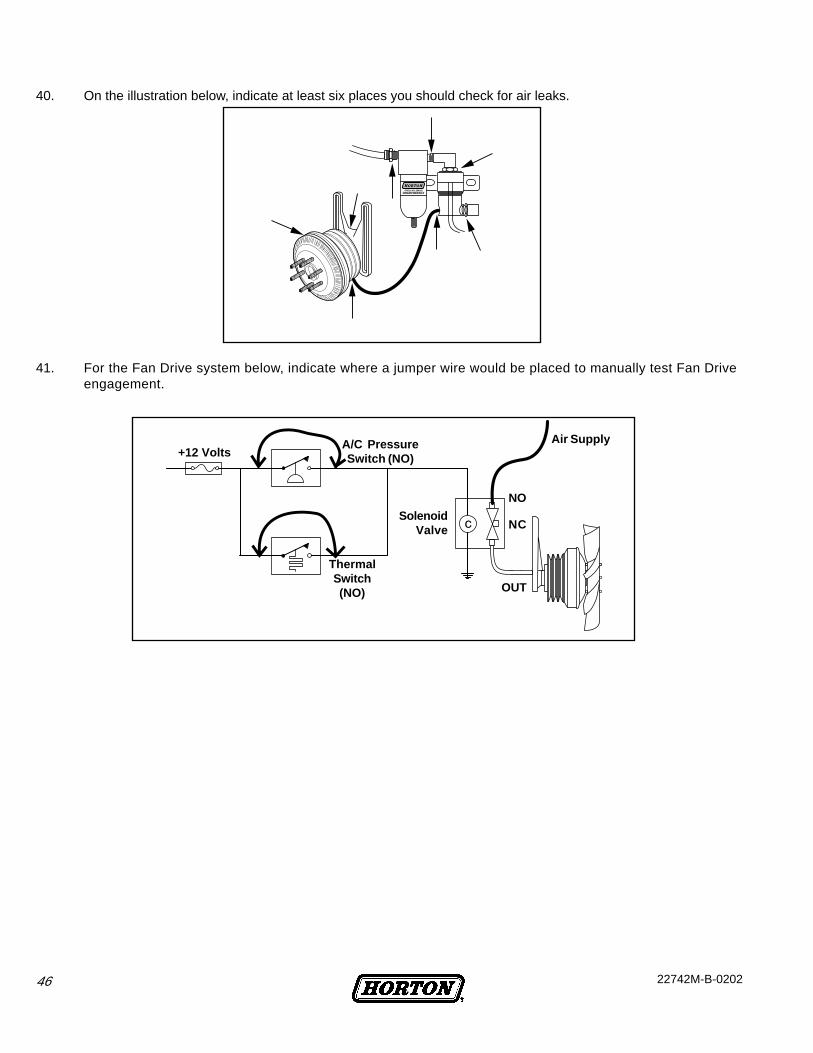
40. On the illustration below, indicate at least six places you should check for air leaks.
41. For the Fan Drive system below, indicate where a jumper wire would be placed to manually test Fan Driveengagement.
Air Supply+12 Volts
A/C PressureSwitch (NO)
SolenoidValve
ThermalSwitch(NO) OUT
NO
NC
44 22742M-B-0202
Review Answers - Fan Drive Service
1. DriveMaster Fan Drive parts that are visible externally are the Fan Mounting Disc, Friction Liner, Air ChamberSeal, and Journal Bracket. True / False
2. The two most commonly replaced parts are the Fan Mounting Disc and Friction Liner. True / False
3. A DriveMaster Seal Kit would be the most appropriate choice if: a) an air leak has developed inside the FanDrive , b) the Bearings are running rough or if the Fan Drive needs to be completely rebuilt, c) the Fan MountingDisc is damaged, d) the Friction Liner is worn.
4. A DriveMaster Super Kit would be the most appropriate choice if: a) an air leak has developed inside the FanDrive, b) the Bearings are running rough or if the Fan Drive needs to be completely rebuilt , c) the FanMounting Disc is damaged, d) the Friction Liner is worn.
5. A DriveMaster Friction Disc Kit would be the most appropriate choice if: a) an air leak has developed inside theFan Drive, b) the Bearings are running rough or if the Fan Drive needs to be completely rebuilt, c) the FanMounting Disc is damaged , d) the Friction Liner is worn.
6. A DriveMaster Friction Liner Kit would be the most appropriate choice if: a) an air leak has developed inside theFan Drive, b) the Bearings are running rough or if the Fan Drive needs to be completely rebuilt, c) the FanMounting Disc is damaged, d) the Friction Liner is worn .
7. Before removing the Fan Drive from the vehicle, it is important to: a) turn the ignition off, b) apply the parkingbrake, c) block the wheels, d) bleed the air from the reservoir, e) all the above .
8. Applying 80-120 PSI [5.44 - 8.16 bar] air pressure to the Fan Drive air inlet will aid in removing the FanMounting Disc. True / False
9. The Jack Bolt is loosened by turning it counter-clockwise using a C55 Torx bit. True / False
10. Pitting or blistering on the inside contact surface of the Fan Mounting Disc is cause for replacement. True / False
11. The Cage Nut from the repair kit keeps the Spring Housing/Piston Assembly together during disassembly.True / False
12. Before removing the Friction Liner, air pressure should be: Off / On
13. The air chamber is located directly underneath the Spring Housing/Piston Assembly. True / False
14. Moisture inside the Air Chamber is normally just routine condensation. True / False
15. When checking the Air Chamber Seals, wear on the Face Seal may indicate dirt exists in the air system.True / False
16. The Air Chamber Cap Retaining Ring must be removed before removing the Air Chamber Cap. True / False
17. First the Bearing Nut is removed, then the Sheave can be removed from the Journal Bracket. True / False
18. The chevron markings on the Bearings must be aligned to form an arrow. True / False
19. The chevron markings on the Bearings need to be aligned when using Spacers. True / False
4522742M-B-0202
20. New Bearings must be disassembled and lubricated. True / False
21. When installing the Bearings, only the outer races should be pressed on. True / False
22. When replacing the Air Cartridge, the curved side of the beveled Retaining Ring faces the cartridge. True / False
23. Eye safety protection should be used when removing the Retaining Ring of the Air Cartridge. True / False
24. The O-rings of a new Air Cartridge Assembly are lubricated: a) before , or b) after, installation.
25. When replacing the Bearing Nut, the hex faces down and the relief of the nut points away from the JournalBracket and Bearings. True / False
26. The Friction Liner should be properly lubricated before installation. True / False
27. When reinstalling the Spring Housing/Piston Assembly, the “V” of the main Air Chamber Seal faces down in theSheave. True / False
28. The Button Head Screws should be alternately and evenly tightened when replacing the Friction Liner.True / False
29. When reinstalling the Spring Housing/Piston Assembly, grease should be applied: a) deep into the Air Chamber,b) along the edge of the Friction Liner, c) only in the immediate area of the Air Chamber Seal .
30. When lubricating the Air Chamber Seal, use only the amount that fully covers the seal. True / False
31. When installing the Fan Mounting Disc, air must be blocked from the air chamber to remove the Cage Nut and toensure proper Jack Bolt torque. True / False
32. When removing or installing the DriveMaster, the best way to protect the radiator is by using cardboard betweenthe fan and radiator. True / False
33. Belts should be tensioned according to: a) Fan Drive specifications, b) industry standards, c) manufacturer orvehicle specifications .
34. A belt tensioner should be used to determine proper belt tightness as listed in the manufacturer or vehiclespecifications. True / False
35. Air leaks are the #1 cause of Fan Drive problems. True / False
36. When observing Fan Drive operation, it is a good idea to look for vibration, Fan blade contact, or Fan Driveslippage. True / False
37. The Fan Drive air filter should be drained and inspected for contaminants: a) weekly , b) monthly, c) annually
38. 25,000 mile (40,000 Km) PM requirements include checking the Fan Drive bearings, Friction Disc facing, wiring,overheating, and proper engagement and disengagement. True / False
39. If an air leak is not fixed the Fan Drive may start to slip and overheat. True / False
46 22742M-B-0202
40. On the illustration below, indicate at least six places you should check for air leaks.
41. For the Fan Drive system below, indicate where a jumper wire would be placed to manually test Fan Driveengagement.
Air Supply+12 Volts
A/C PressureSwitch (NO)
SolenoidValve
ThermalSwitch(NO) OUT
NO
NC
4722742M-B-0202
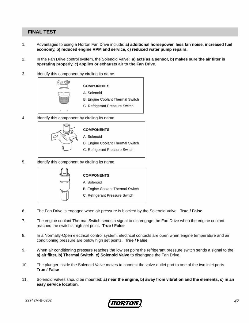
FINAL TEST
1. Advantages to using a Horton Fan Drive include: a) additional horsepower, less fan noise, increased fueleconomy, b) reduced engine RPM and service, c) reduced water pump repairs.
2. In the Fan Drive control system, the Solenoid Valve: a) acts as a sensor, b) makes sure the air filter isoperating properly, c) applies or exhausts air to the Fan Drive.
3. Identify this component by circling its name.
4. Identify this component by circling its name.
5. Identify this component by circling its name.
6. The Fan Drive is engaged when air pressure is blocked by the Solenoid Valve. True / False
7. The engine coolant Thermal Switch sends a signal to dis-engage the Fan Drive when the engine coolantreaches the switch’s high set point. True / False
8. In a Normally-Open electrical control system, electrical contacts are open when engine temperature and airconditioning pressure are below high set points. True / False
9. When air conditioning pressure reaches the low set point the refrigerant pressure switch sends a signal to the:a) air filter, b) Thermal Switch, c) Solenoid Valve to disengage the Fan Drive.
10. The plunger inside the Solenoid Valve moves to connect the valve outlet port to one of the two inlet ports.True / False
11. Solenoid Valves should be mounted: a) near the engine, b) away from vibration and the elements, c) in aneasy service location.
COMPONENTS
A. Solenoid
B. Engine Coolant Thermal Switch
C. Refrigerant Pressure Switch
COMPONENTS
A. Solenoid
B. Engine Coolant Thermal Switch
C. Refrigerant Pressure Switch
COMPONENTS
A. Solenoid
B. Engine Coolant Thermal Switch
C. Refrigerant Pressure Switch
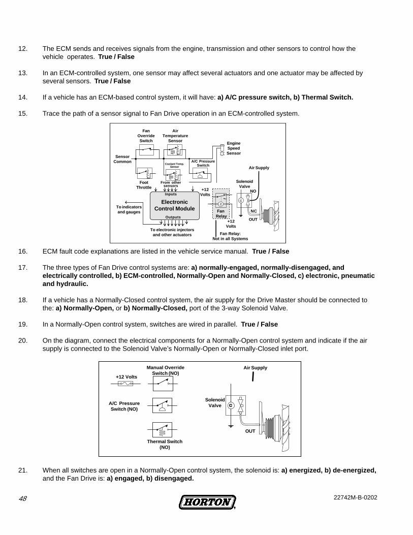
48 22742M-B-0202
12. The ECM sends and receives signals from the engine, transmission and other sensors to control how thevehicle operates. True / False
13. In an ECM-controlled system, one sensor may affect several actuators and one actuator may be affected byseveral sensors. True / False
14. If a vehicle has an ECM-based control system, it will have: a) A/C pressure switch, b) Thermal Switch.
15. Trace the path of a sensor signal to Fan Drive operation in an ECM-controlled system.
16. ECM fault code explanations are listed in the vehicle service manual. True / False
17. The three types of Fan Drive control systems are: a) normally-engaged, normally-disengaged, andelectrically controlled, b) ECM-controlled, Normally-Open and Normally-Closed, c) electronic, pneumaticand hydraulic.
18. If a vehicle has a Normally-Closed control system, the air supply for the Drive Master should be connected tothe: a) Normally-Open, or b) Normally-Closed, port of the 3-way Solenoid Valve.
19. In a Normally-Open control system, switches are wired in parallel. True / False
20. On the diagram, connect the electrical components for a Normally-Open control system and indicate if the airsupply is connected to the Solenoid Valve’s Normally-Open or Normally-Closed inlet port.
21. When all switches are open in a Normally-Open control system, the solenoid is: a) energized, b) de-energized,and the Fan Drive is: a) engaged, b) disengaged.
SolenoidValve
Thermal Switch(NO)
A/C PressureSwitch (NO)
Manual OverrideSwitch (NO)
+12 Volts
Air Supply
OUT
Fan Relay:Not in all Systems
FanOverrideSwitch
SensorCommon
FootThrottle
To indicatorsand gauges
Coolant Temp.Sensor
From othersensors
Inputs
ElectronicControl Module
Outputs
To electronic injectorsand other actuators
AirTemperature
Sensor
A/C PressureSwitch
EngineSpeedSensor
Air Supply
SolenoidValve
FanRelay
+12Volts
NO
NC
OUT
+12Volts
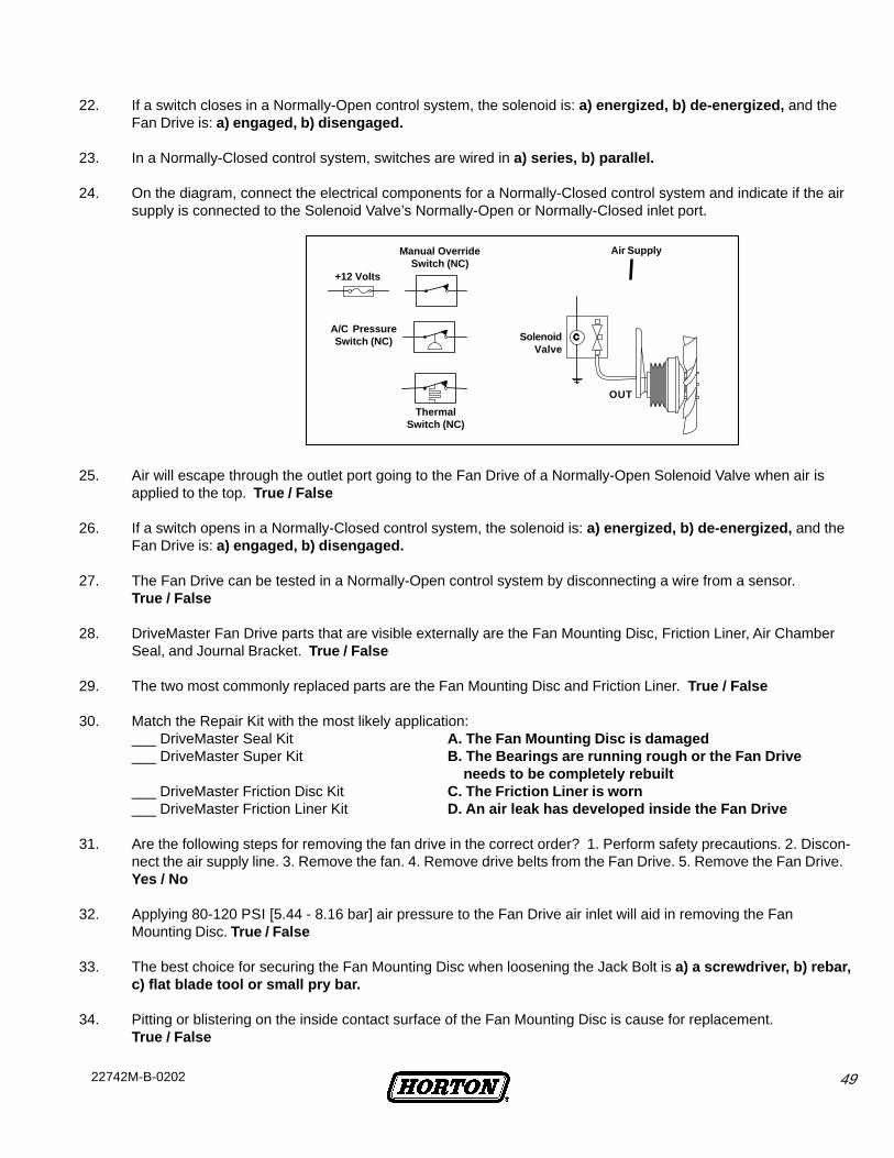
4922742M-B-0202
25. Air will escape through the outlet port going to the Fan Drive of a Normally-Open Solenoid Valve when air isapplied to the top. True / False
26. If a switch opens in a Normally-Closed control system, the solenoid is: a) energized, b) de-energized, and theFan Drive is: a) engaged, b) disengaged.
27. The Fan Drive can be tested in a Normally-Open control system by disconnecting a wire from a sensor.True / False
28. DriveMaster Fan Drive parts that are visible externally are the Fan Mounting Disc, Friction Liner, Air ChamberSeal, and Journal Bracket. True / False
29. The two most commonly replaced parts are the Fan Mounting Disc and Friction Liner. True / False
30. Match the Repair Kit with the most likely application:___ DriveMaster Seal Kit A. The Fan Mounting Disc is damaged___ DriveMaster Super Kit B. The Bearings are running rough or the Fan Drive
needs to be completely rebuilt___ DriveMaster Friction Disc Kit C. The Friction Liner is worn___ DriveMaster Friction Liner Kit D. An air leak has developed inside the Fan Drive
31. Are the following steps for removing the fan drive in the correct order? 1. Perform safety precautions. 2. Discon-nect the air supply line. 3. Remove the fan. 4. Remove drive belts from the Fan Drive. 5. Remove the Fan Drive.Yes / No
32. Applying 80-120 PSI [5.44 - 8.16 bar] air pressure to the Fan Drive air inlet will aid in removing the FanMounting Disc. True / False
33. The best choice for securing the Fan Mounting Disc when loosening the Jack Bolt is a) a screwdriver, b) rebar,c) flat blade tool or small pry bar.
34. Pitting or blistering on the inside contact surface of the Fan Mounting Disc is cause for replacement.True / False
22. If a switch closes in a Normally-Open control system, the solenoid is: a) energized, b) de-energized, and theFan Drive is: a) engaged, b) disengaged.
23. In a Normally-Closed control system, switches are wired in a) series, b) parallel.
24. On the diagram, connect the electrical components for a Normally-Closed control system and indicate if the airsupply is connected to the Solenoid Valve’s Normally-Open or Normally-Closed inlet port.
ThermalSwitch (NC)
SolenoidValve
+12 Volts
Manual OverrideSwitch (NC)
A/C PressureSwitch (NC)
Air Supply
OUT
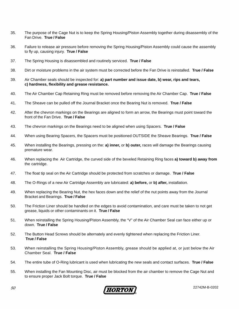
50 22742M-B-0202
35. The purpose of the Cage Nut is to keep the Spring Housing/Piston Assembly together during disassembly of theFan Drive. True / False
36. Failure to release air pressure before removing the Spring Housing/Piston Assembly could cause the assemblyto fly up, causing injury. True / False
37. The Spring Housing is disassembled and routinely serviced. True / False
38. Dirt or moisture problems in the air system must be corrected before the Fan Drive is reinstalled. True / False
39. Air Chamber seals should be inspected for: a) part number and issue date, b) wear, rips and tears,c) hardness, flexibility and grease resistance.
40. The Air Chamber Cap Retaining Ring must be removed before removing the Air Chamber Cap. True / False
41. The Sheave can be pulled off the Journal Bracket once the Bearing Nut is removed. True / False
42. After the chevron markings on the Bearings are aligned to form an arrow, the Bearings must point toward thefront of the Fan Drive. True / False
43. The chevron markings on the Bearings need to be aligned when using Spacers. True / False
44. When using Bearing Spacers, the Spacers must be positioned OUTSIDE the Sheave Bearings. True / False
45. When installing the Bearings, pressing on the: a) inner, or b) outer, races will damage the Bearings causingpremature wear.
46. When replacing the Air Cartridge, the curved side of the beveled Retaining Ring faces a) toward b) away fromthe cartridge.
47. The float tip seal on the Air Cartridge should be protected from scratches or damage. True / False
48. The O-Rings of a new Air Cartridge Assembly are lubricated: a) before, or b) after, installation.
49. When replacing the Bearing Nut, the hex faces down and the relief of the nut points away from the JournalBracket and Bearings. True / False
50. The Friction Liner should be handled on the edges to avoid contamination, and care must be taken to not getgrease, liquids or other contaminants on it. True / False
51. When reinstalling the Spring Housing/Piston Assembly, the “V” of the Air Chamber Seal can face either up ordown. True / False
52. The Button Head Screws should be alternately and evenly tightened when replacing the Friction Liner. True / False
53. When reinstalling the Spring Housing/Piston Assembly, grease should be applied at, or just below the AirChamber Seal. True / False
54. The entire tube of O-Ring lubricant is used when lubricating the new seals and contact surfaces. True / False
55. When installing the Fan Mounting Disc, air must be blocked from the air chamber to remove the Cage Nut andto ensure proper Jack Bolt torque. True / False
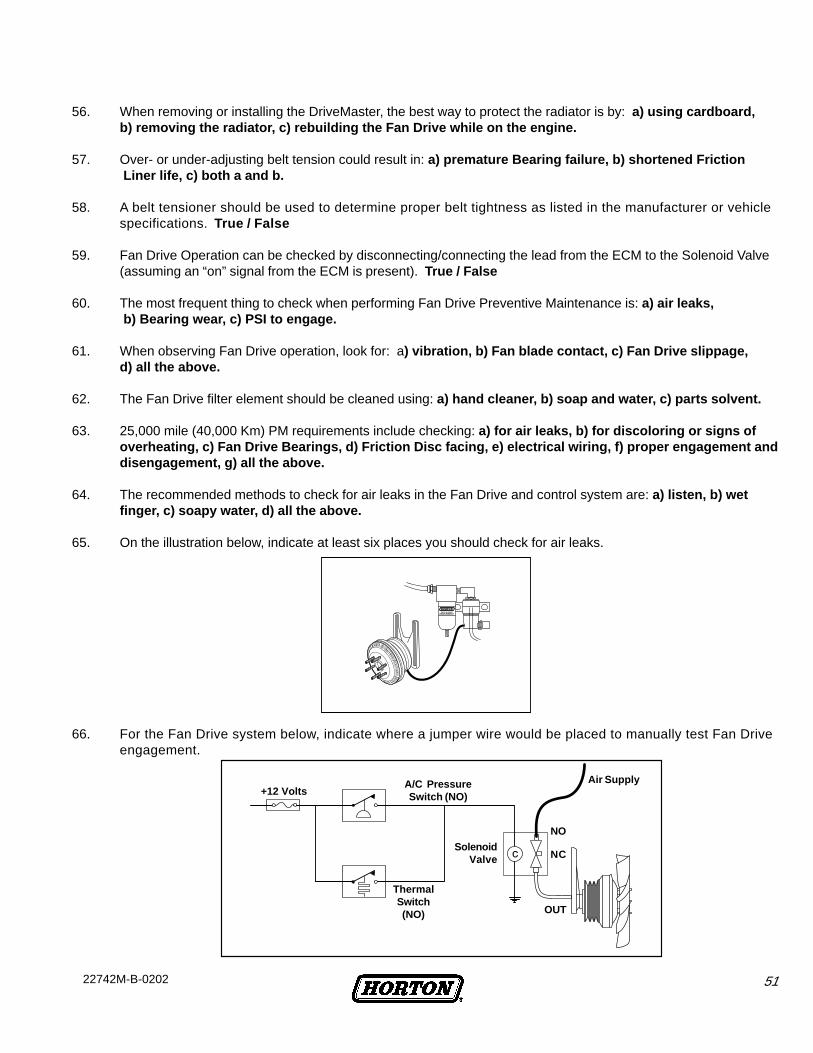
5122742M-B-0202
56. When removing or installing the DriveMaster, the best way to protect the radiator is by: a) using cardboard,b) removing the radiator, c) rebuilding the Fan Drive while on the engine.
57. Over- or under-adjusting belt tension could result in: a) premature Bearing failure, b) shortened Friction Liner life, c) both a and b.
58. A belt tensioner should be used to determine proper belt tightness as listed in the manufacturer or vehiclespecifications. True / False
59. Fan Drive Operation can be checked by disconnecting/connecting the lead from the ECM to the Solenoid Valve(assuming an “on” signal from the ECM is present). True / False
60. The most frequent thing to check when performing Fan Drive Preventive Maintenance is: a) air leaks, b) Bearing wear, c) PSI to engage.
61. When observing Fan Drive operation, look for: a) vibration, b) Fan blade contact, c) Fan Drive slippage,d) all the above.
62. The Fan Drive filter element should be cleaned using: a) hand cleaner, b) soap and water, c) parts solvent.
63. 25,000 mile (40,000 Km) PM requirements include checking: a) for air leaks, b) for discoloring or signs ofoverheating, c) Fan Drive Bearings, d) Friction Disc facing, e) electrical wiring, f) proper engagement anddisengagement, g) all the above.
64. The recommended methods to check for air leaks in the Fan Drive and control system are: a) listen, b) wetfinger, c) soapy water, d) all the above.
65. On the illustration below, indicate at least six places you should check for air leaks.
66. For the Fan Drive system below, indicate where a jumper wire would be placed to manually test Fan Driveengagement.
Air Supply+12 Volts
A/C PressureSwitch (NO)
SolenoidValve
ThermalSwitch(NO) OUT
NO
NC

52 22742M-B-0202
1. Advantages to using a Horton Fan Drive include: a) additional horsepower, less fan noise, increased fueleconomy , b) reduced engine RPM and service, c) reduced water pump repairs.
2. In the Fan Drive control system, the Solenoid Valve: a) acts as a sensor, b) makes sure the air filter is operatingproperly, c) applies or exhausts air to the Fan Drive .
3. Identify this component by circling its name.
4. Identify this component by circling its name.
5. Identify this component by circling its name.
6. The Fan Drive is engaged when air pressure is blocked by the Solenoid Valve. True / False
7. The engine coolant Thermal Switch sends a signal to dis-engage the Fan Drive when the engine coolantreaches the switch’s high set point. True / False
8. In a Normally-Open electrical control system, electrical contacts are open when engine temperature and airconditioning pressure are below high set points. True / False
9. When air conditioning pressure reaches the low set point the refrigerant pressure switch sends a signal to the:a) air filter, b) Thermal Switch, c) Solenoid Valve to disengage the Fan Drive.
10. The plunger inside the Solenoid Valve moves to connect the valve outlet port to one of the two inlet ports.True / False
11. Solenoid Valves should be mounted: a) near the engine, b) away from vibration and the elements , c) in aneasy service location.
Final Test Answers
COMPONENTS
A. Solenoid
B. Engine Coolant Thermal Switch
C. Refrigerant Pressure Switch
COMPONENTS
A. Solenoid
B. Engine Coolant Thermal Switch
C. Refrigerant Pressure Switch
COMPONENTS
A. Solenoid
B. Engine Coolant Thermal Switch
C. Refrigerant Pressure Switch
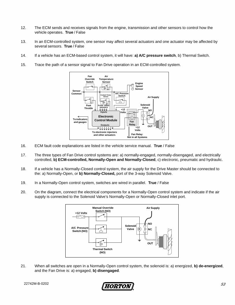
5322742M-B-0202
12. The ECM sends and receives signals from the engine, transmission and other sensors to control how thevehicle operates. True / False
13. In an ECM-controlled system, one sensor may affect several actuators and one actuator may be affected byseveral sensors. True / False
14. If a vehicle has an ECM-based control system, it will have: a) A/C pressure switch , b) Thermal Switch.
15. Trace the path of a sensor signal to Fan Drive operation in an ECM-controlled system.
16. ECM fault code explanations are listed in the vehicle service manual. True / False
17. The three types of Fan Drive control systems are: a) normally-engaged, normally-disengaged, and electricallycontrolled, b) ECM-controlled, Normally-Open and Normally-Closed , c) electronic, pneumatic and hydraulic.
18. If a vehicle has a Normally-Closed control system, the air supply for the Drive Master should be connected tothe: a) Normally-Open, or b) Normally-Closed, port of the 3-way Solenoid Valve.
19. In a Normally-Open control system, switches are wired in parallel. True / False
20. On the diagram, connect the electrical components for a Normally-Open control system and indicate if the airsupply is connected to the Solenoid Valve’s Normally-Open or Normally-Closed inlet port.
21. When all switches are open in a Normally-Open control system, the solenoid is: a) energized, b) de-energized ,and the Fan Drive is: a) engaged, b) disengaged .
Fan Relay:Not in all Systems
FanOverrideSwitch
SensorCommon
FootThrottle
To indicatorsand gauges
Coolant Temp.Sensor
From othersensors
Inputs
ElectronicControl Module
Outputs
To electronic injectorsand other actuators
AirTemperature
Sensor
A/C PressureSwitch
EngineSpeedSensor
Air Supply
SolenoidValve
FanRelay
+12Volts
NO
NC
OUT
+12Volts
NC
NOSolenoid
Valve
Thermal Switch(NO)
A/C PressureSwitch (NO)
Manual OverrideSwitch (NO)
+12 Volts
OUT
Air Supply
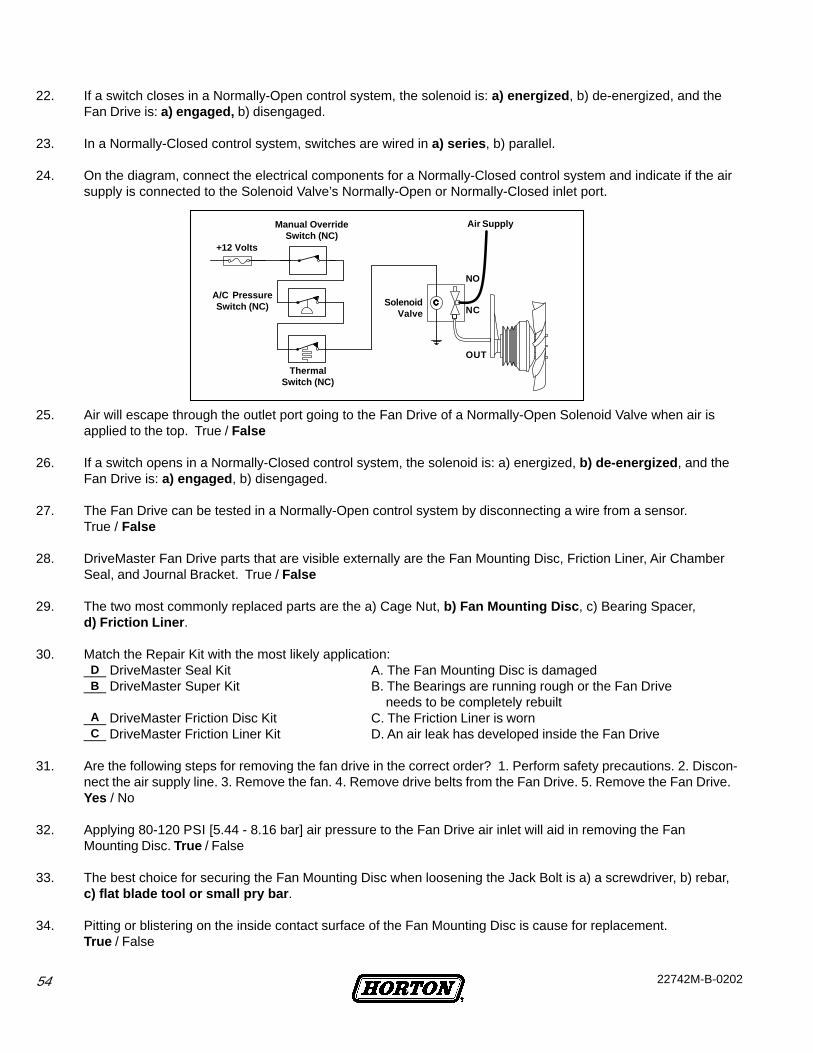
54 22742M-B-0202
22. If a switch closes in a Normally-Open control system, the solenoid is: a) energized , b) de-energized, and theFan Drive is: a) engaged, b) disengaged.
23. In a Normally-Closed control system, switches are wired in a) series , b) parallel.
24. On the diagram, connect the electrical components for a Normally-Closed control system and indicate if the airsupply is connected to the Solenoid Valve’s Normally-Open or Normally-Closed inlet port.
25. Air will escape through the outlet port going to the Fan Drive of a Normally-Open Solenoid Valve when air isapplied to the top. True / False
26. If a switch opens in a Normally-Closed control system, the solenoid is: a) energized, b) de-energized , and theFan Drive is: a) engaged , b) disengaged.
27. The Fan Drive can be tested in a Normally-Open control system by disconnecting a wire from a sensor.True / False
28. DriveMaster Fan Drive parts that are visible externally are the Fan Mounting Disc, Friction Liner, Air ChamberSeal, and Journal Bracket. True / False
29. The two most commonly replaced parts are the a) Cage Nut, b) Fan Mounting Disc , c) Bearing Spacer,d) Friction Liner .
30. Match the Repair Kit with the most likely application:___ DriveMaster Seal Kit A. The Fan Mounting Disc is damaged___ DriveMaster Super Kit B. The Bearings are running rough or the Fan Drive
needs to be completely rebuilt___ DriveMaster Friction Disc Kit C. The Friction Liner is worn___ DriveMaster Friction Liner Kit D. An air leak has developed inside the Fan Drive
31. Are the following steps for removing the fan drive in the correct order? 1. Perform safety precautions. 2. Discon-nect the air supply line. 3. Remove the fan. 4. Remove drive belts from the Fan Drive. 5. Remove the Fan Drive.Yes / No
32. Applying 80-120 PSI [5.44 - 8.16 bar] air pressure to the Fan Drive air inlet will aid in removing the FanMounting Disc. True / False
33. The best choice for securing the Fan Mounting Disc when loosening the Jack Bolt is a) a screwdriver, b) rebar,c) flat blade tool or small pry bar .
34. Pitting or blistering on the inside contact surface of the Fan Mounting Disc is cause for replacement.True / False
C
ThermalSwitch (NC)
SolenoidValve NC
OUT
NO
+12 Volts
Manual OverrideSwitch (NC)
A/C PressureSwitch (NC)
Air Supply
A
BD
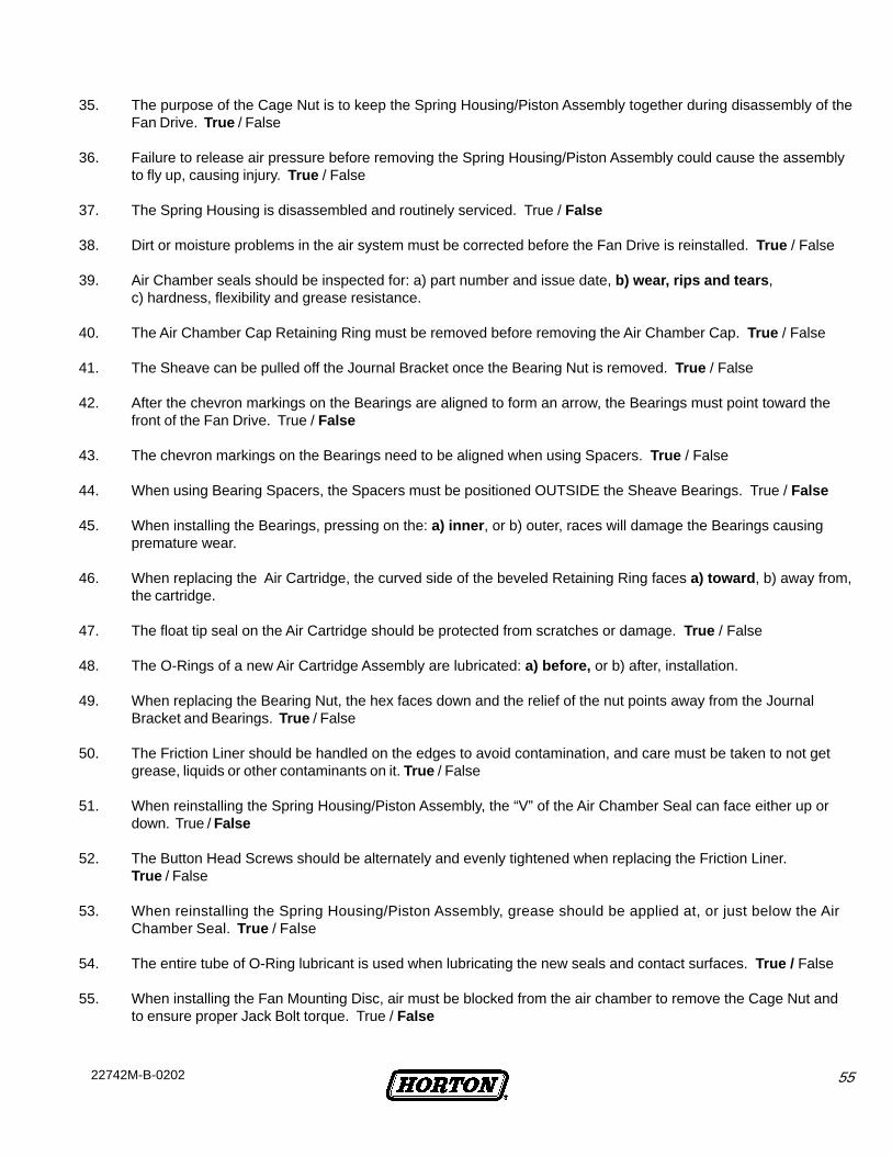
5522742M-B-0202
35. The purpose of the Cage Nut is to keep the Spring Housing/Piston Assembly together during disassembly of theFan Drive. True / False
36. Failure to release air pressure before removing the Spring Housing/Piston Assembly could cause the assemblyto fly up, causing injury. True / False
37. The Spring Housing is disassembled and routinely serviced. True / False
38. Dirt or moisture problems in the air system must be corrected before the Fan Drive is reinstalled. True / False
39. Air Chamber seals should be inspected for: a) part number and issue date, b) wear, rips and tears ,c) hardness, flexibility and grease resistance.
40. The Air Chamber Cap Retaining Ring must be removed before removing the Air Chamber Cap. True / False
41. The Sheave can be pulled off the Journal Bracket once the Bearing Nut is removed. True / False
42. After the chevron markings on the Bearings are aligned to form an arrow, the Bearings must point toward thefront of the Fan Drive. True / False
43. The chevron markings on the Bearings need to be aligned when using Spacers. True / False
44. When using Bearing Spacers, the Spacers must be positioned OUTSIDE the Sheave Bearings. True / False
45. When installing the Bearings, pressing on the: a) inner , or b) outer, races will damage the Bearings causingpremature wear.
46. When replacing the Air Cartridge, the curved side of the beveled Retaining Ring faces a) toward , b) away from,the cartridge.
47. The float tip seal on the Air Cartridge should be protected from scratches or damage. True / False
48. The O-Rings of a new Air Cartridge Assembly are lubricated: a) before, or b) after, installation.
49. When replacing the Bearing Nut, the hex faces down and the relief of the nut points away from the JournalBracket and Bearings. True / False
50. The Friction Liner should be handled on the edges to avoid contamination, and care must be taken to not getgrease, liquids or other contaminants on it. True / False
51. When reinstalling the Spring Housing/Piston Assembly, the “V” of the Air Chamber Seal can face either up ordown. True / False
52. The Button Head Screws should be alternately and evenly tightened when replacing the Friction Liner.True / False
53. When reinstalling the Spring Housing/Piston Assembly, grease should be applied at, or just below the AirChamber Seal. True / False
54. The entire tube of O-Ring lubricant is used when lubricating the new seals and contact surfaces. True / False
55. When installing the Fan Mounting Disc, air must be blocked from the air chamber to remove the Cage Nut andto ensure proper Jack Bolt torque. True / False
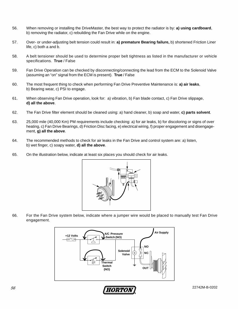
56 22742M-B-0202
56. When removing or installing the DriveMaster, the best way to protect the radiator is by: a) using cardboard ,b) removing the radiator, c) rebuilding the Fan Drive while on the engine.
57. Over- or under-adjusting belt tension could result in: a) premature Bearing failure, b) shortened Friction Linerlife, c) both a and b.
58. A belt tensioner should be used to determine proper belt tightness as listed in the manufacturer or vehiclespecifications. True / False
59. Fan Drive Operation can be checked by disconnecting/connecting the lead from the ECM to the Solenoid Valve(assuming an “on” signal from the ECM is present). True / False
60. The most frequent thing to check when performing Fan Drive Preventive Maintenance is: a) air leaks ,b) Bearing wear, c) PSI to engage.
61. When observing Fan Drive operation, look for: a) vibration, b) Fan blade contact, c) Fan Drive slippage,d) all the above .
62. The Fan Drive filter element should be cleaned using: a) hand cleaner, b) soap and water, c) parts solvent .
63. 25,000 mile (40,000 Km) PM requirements include checking: a) for air leaks, b) for discoloring or signs of overheating, c) Fan Drive Bearings, d) Friction Disc facing, e) electrical wiring, f) proper engagement and disengage-ment, g) all the above .
64. The recommended methods to check for air leaks in the Fan Drive and control system are: a) listen,b) wet finger, c) soapy water, d) all the above .
65. On the illustration below, indicate at least six places you should check for air leaks.
66. For the Fan Drive system below, indicate where a jumper wire would be placed to manually test Fan Driveengagement.
Air Supply+12 Volts
A/C PressureSwitch (NO)
SolenoidValve
ThermalSwitch(NO) OUT
NO
NC

Horton, Inc.2565 Walnut St.Roseville, MN 55113651-361-6400Toll-free: 1-800-621-1320Website: www.hortoninc.come-mail: [email protected]
© 2002 Horton, Inc.All rights reserved.
22742M-B-0202