dmrb volume 7 section 3 - hd 30/08 - maintenance
TRANSCRIPT

volume 7 pavement design and maintenance section 3 pavement maintenance assessment
part 3
Hd 30/08
maintenance assessment procedure
summarY
This standard includes the general procedure for assessing the need for maintenance of road pavements and a general guide to the design of maintenance treatments. It has been revised to reflect changes in HD 29/08 and value management procedures.
instructions for use
1. Remove existing HD 30/99, which is now replaced by HD 30/08 and archive as appropriate.
2. Insert HD 30/08 into Volume 7, Section 3.
3. Please archive this sheet as appropriate.
Note: A quarterly index with a full set of Volume Contents Pages is available separately from The Stationery Office Ltd.
design manual for roads and Bridges
may 2008

design manual for roads and Bridges Hd 30/08 volume 7, section 3, part 3
tHe HigHwaYs agencY
scottisH government
welsH assemBlY government llYwodraetH cYnulliad cYmru
tHe department for regional development nortHern ireland
Maintenance Assessment Procedure
Summary: This standard includes the general procedure for assessing the need for maintenance of road pavements and a general guide to the design of maintenancetreatments.IthasbeenrevisedtoreflectchangesinHD29/08and value management procedures.

may 2008
volume 7 section 3 part 3 Hd 30/08
registration of amendments
amend no
page no signature & date of incorporation of
amendments
amend no page no signature & date of incorporation of
amendments
registration of amendments

may 2008
volume 7 section 3 part 3 Hd 30/08
registration of amendments
amend no
page no signature & date of incorporation of
amendments
amend no page no signature & date of incorporation of
amendments
registration of amendments

volume 7 pavement design and maintenance section 3 pavement maintenance assessment
part 3
Hd 30/08
maintenance assessment procedure
contents
Chapter
1. Introduction
2. Pavement Deterioration Mechanisms
3. Network Survey Data
4. Collection and Review of Existing Data
5. Scheme Level Surveys and Investigations
6. Interpretation
7. Treatment Design
8. References and Bibliography
9. Enquiries
design manual for roads and Bridges
may 2008

volume 7 section 3 part 3 Hd 30/08
1/1
chapter 1 introduction
may 2008
1. introduction
mandatory sections
1.1 Sections of this document which form part of the Standards of the Overseeing Organisations are highlighted by being contained in boxes. These are the sections with which the design organisations must comply, or must have agreed a suitable departure from Standard with the relevant Overseeing Organisation. The remainder of the document contains advice and enlargement which is commended to design organisations for their consideration.
general
1.2 Road pavements do not last indefinitely. At some stage in their lives signs of wear such as polishing, rutting, fretting or ravelling (surface disintegration), and cracking may show on the surface. Maintenance is required when these signs of wear are judged to affect the standards of service provided to the road user and the integrity of the pavement structure. To accomplish this task in the most cost-effective manner, it is necessary to use a logical assessment procedure to enable the correct maintenance treatment to be carried out at the most advantageous time. Regardless of whether strengthening or just resurfacing is being contemplated, carefully considered and designed pavement assessment is essential. This is to ensure that the strengthening is warranted and is of the right degree, and to avoid re-surfacing being laid on a structurally inadequate pavement. For the trunk road network in England, maintenance proposals are reviewed through the Value Management process which requires documentary evidence for each scheme of appropriate investigation, interpretation and treatment selection.
1.3 In-service roads, even those built up over very many years, usually conform to one of the flexible or rigid construction types described in HD 26 (DMRB 7.2.3). A uniform approach to the collection of condition information, its presentation and assessment is described in this Part which can be applied to all these pavement types, although detailed procedures will vary depending on the specific type of construction present. Deterioration is caused by a combination of factors and this Part is not intended to be a substitute for the expertise and judgements of the designer. Every case
mufee
sco
1.4assThetec7.3resPartreamain HIntetec
1.5roaunube in tthethepra
1.6thisappWeconresmu
im
st be treated on its merits and the designer must not l constrained to use only the methods described.
pe
This Part outlines the general procedure for essing the need for maintenance of road pavements. various types of road survey and investigation
hniques involved are described in HD 29 (DMRB .2). The details of routine testing for skidding istance are contained in HD 28 (DMRB 7.3.1). This t also provides a guide to the design of maintenance tments but does not cover routine or minor
intenance, some aspects of which are mentioned D 31 (DMRB 7.4.1) and HD 32 (DMRB 7.4.2). rpretation of the various surveys and investigation
hniques is contained in this Part.
This Part does not deal with the assessment of d pavements which have failed or deteriorated in an sual manner or where contractual warranties may
in force, e.g. substantial defects appearing very early he expected life of the pavement. In these situations investigation and assessment methods would reflect specific circumstances but could be based on the ctices of HD 29 (DMRB 7.3.2) and this Part.
The various references made within the text of Part to the Network Maintenance Manual (NMM) ly only to England. For guidance in Wales, the lsh Trunk Road Maintenance Manual must be sulted. Guidance on requirements applying to the
t of the UK, where these are not already in the text, st be obtained from the Overseeing Organisation.
plementation
1.7 This Part must be used forthwith on all schemes for the improvement and maintenance of trunk roads including motorways, currently being prepared, provided that, in the opinion of the Overseeing Organisation, this would not result in significant additional expense or delay. Design organisations must confirm its application to particular schemes with the Overseeing Organisation.

volume 7 section 3 part 3 Hd 30/08
chapter 1 introduction
use in northern ireland
1.8 For use in Northern Ireland, this Standard will apply to those roads designated by the Overseeing Organisation.
mutual recognition
1.9 The construction and maintenance of highway pavements will normally be carried out under contracts incorporating the Overseeing Organisations’ Specification for Highway Works (SHW) which is contained in the Manual of Contract Documents for Highway Works Volume 1 (MCHW 1). In such cases products conforming to equivalent standards and specification of other Member States (MS) of the European Economic Area (EEA) or a State which is party to a relevant agreement with the European Union and tests undertaken in other MS of the EEA or a State which is party to a relevant agreement with the European Union will be acceptable in accordance with the terms of Clauses 104 and 105 (MCHW 1.100). Any contract not containing these Clauses must contain suitable clauses of mutual recognition having the same effect, regarding which advice must be sought.
Health and safety
1.10 All survey and data collection on or in the vicinity of highway pavements must be carried out in accordance with:
• Health and Safety at Work Act (1974);
• Management of Health and Safety at Work Regulations (1999);
• Construction (Design and Management) Regulations (2007) (CDM Regulations);
• Traffic Signs Manual Chapter 8 (2006); and
• Safety at Street Works and Road Works – A Code of Practice.
m
1.pa
1/2
1.11 In Northern Ireland, the relevant Health and Safety documents are:
• Construction (Design and Management) Regulations (Northern Ireland) 2007;
• Health and Safety at Work (Northern Ireland) Order 1978;
• Management of Health and Safety at Work Regulations (2000);
• Traffic Signs Manual Chapter 8 (2006); and
• Safety at Street Works and Road Works – A Code of Practice.
1.12 For the Highways Agency network, further information on Health and Safety is given in Part 1 of the Network Management Manual.
aintenance assessment process
13 The principal stages in assessing the need for vement maintenance are shown in Figure 1.1.
may 2008

volume 7 section 3 part 3 Hd 30/08
chapter 1 introduction
1. Network Survey Data and identification of possible maintenance schemes TRACS or SCANNER, SCRIM, safety, routine or other visual inspections and Deflectograph (for some networks).
Carry out HD 28 investigation if there are SCRIM values < Investigatory Level.
2. collection and review of existing data e.g. Traffic, records of age of construction, maintenance, defects and repairs, and previous survey data.
3. plan scheme surveys and investigation
Chapter 5
4. carry out scheme surveys • Pavement: Visual Condition Survey, cores etc. • Other (as required): Earthworks, drainage etc.
Chapter 5
5. interpretation of data
Chapter 5
6. treatment design
Chapter 5
figure 1.1 – investigation and assessment process
glossary
1.14 A glossary and list of principal abbreviations is given in HD 23 (DMRB 7.1.1).
1.15 In this Part, the term ‘asphalt’ replaces ‘bituminous material’ as the generic term for pavement material consisting of mineral aggregate combined with a bitumen binder and which is normally laid by a paver. ‘Asphalt’ includes all bitumen bound base, binder course and surface course mixtures, except surface dressing. The exception to this is indicated below, where ‘bituminous material’ continues in use:
•
1.Mpabocobocoin
may 2008
Deflectograph processing uses the technical terms ‘Equivalent Thickness of Sound Bituminous Material (ESBM)’, ‘Total Thickness of Bituminous Material (TTBM)’ and Base Type Classification ‘BITS’. Use of the term ‘asphalt’ would require changes to these acronyms and to text in the associated software.
16 In this Part, the term ‘Hydraulically Bound ixture’ or ‘HBM’ is used as the generic term for vement material consisting of mineral aggregate und with cement, slag, lime or fly ash; or a mbination thereof. The terms ‘lean concrete’, ‘cement und material’ or ‘CBM’ are no longer used except in nnection with Base Type Classification ‘CEMT’ used Deflectograph processing.
1/3

volume 7 section 3 part 3 Hd 30/08
tion mecHanisms
chapter 2 pavement deterioration mechanisms
2. pavement deteriora
introduction
2.1 Although there are many common factors, there are also some differences in the surface and structural deterioration mechanisms of pavements depending on whether they are, generally, of flexible or rigid construction.
2.2 The surfaces of all pavements eventually suffer from loss of skidding resistance. Loss of texture and rutting can also occur, particularly for surfacing materials which have relatively high binder contents. For surface courses which lose aggregate as a result of environmental deterioration (see Paragraph 2.3) the texture depth may not decrease, indeed it may even increase. The deterioration mechanisms of specific types of pavement, commonly found on the road network are discussed below.
fleXiBle pavements witH aspHalt Base
2.3 Deterioration in flexible pavements with asphalt base is generally associated with traffic loading and/or with environmental factors. Deterioration due to traffic loading is normally associated with the following mechanisms:
• Repeated cycles of tensile strains generated within the bound layers under vehicle loading cause fatigue cracks to initiate in the asphalt. Classical pavement analysis indicated that these cracks would generally initiate at the underside of the asphalt base and then propagate upwards through the material. However, the view of how this mechanism operates in practice on the thick pavements that comprise the greater part of the trunk road and motorway network has been revised following extensive observation and investigation, and is further discussed in Paragraphs 2.4 to 2.6.
• Rutting due to the permanent, cumulative deformation of one or more of the various layers within the pavement structure including the foundation. Where the rutting emanates from the subgrade or pavement foundation and the entire pavement structure is deformed, this is referred to as structural deformation. Rutting that is confined to the asphalt surfacing is termed non-structural.
may 2008
The main environmental causes of pavement deterioration are:
• The asphalt binder may harden over time with consequent effect on the fatigue resisting properties of the mixture. One of the principal mechanisms of binder hardening is held to be oxidation of the bitumen, and this predominantly occurs at the surface of the pavement exposed to air and solar radiation. Strains at the pavement surface caused by both thermal cycling and vehicle loading can eventually lead to cracks appearing at the surface. Over time these may propagate downwards and could ultimately reach the base of the bound layers. The hardening of the bitumen may also affect the cohesion of the mixture and may lead to the loss of aggregate in the surfacing (fretting or surface disintegration).
• As bitumen is a visco-elastic material the performance of asphalt mixtures is influenced by the service temperature. The risk of the accumulation of permanent deformation in the surfacing (non-structural rutting) will, therefore, be increased during periods of hot weather and further exacerbated by slow moving and/or stationary traffic. This risk can be mitigated by the selection of appropriate, well-designed and placed materials (see HD 37).
Less common environmental causes of pavement deterioration include the variation in foundation strength caused by seasonal changes in moisture levels and the action of a freeze-thaw cycle, particularly on cracked pavements of thin construction.
long-life flexible pavements with asphalt Base
2.4 Thick, well constructed flexible pavements with asphalt base on strong foundations do not suffer bottom-up, fatigue cracking of the base or structural deformation (Nunn et al., 1997). Environmental factors can cause cracking to develop at the surface, which will gradually increase in depth. Deformation in these pavements also tends to be limited to the surfacing layers (i.e. is non-structural). Very long pavement lives can be achieved by the removal of any cracked or severely rutted material, before the defect has progressed too deeply, and its replacement with new material.
2/1

volume 7 section 3 part 3 Hd 30/08
chapter 2 pavement deterioration mechanisms
2.5 Criteria based on measured deflection and total thickness of bituminous material may be used to identify flexible pavements with asphalt base with the potential for long life. This identification is carried out as part of Deflectograph data processing, either within HAPMS or with the PANDEF software, described in
Figure 2.1 – Deflectograph-Ba
2.6 The Total Thickness of Bituminous Material (TTBM) shown in Figure 2.1 is the combined thickness of all the contiguous intact asphalt layers present in the pavement, subject to the following criteria:
a) Asphalt surfacing layers (i.e. those within the top 100mm of the existing pavement) are included in TTBM regardless of their condition.
b) Asphalt layers which are known to be severely deteriorated and whose upper surface is at a depth greater than 100mm are not included in TTBM.
c) Any intact asphalt (or deteriorated surfacing material) that is separated from other intact asphalt materials by either a severely deteriorated asphalt layer or any granular layer (either of which must be greater than 25mm thick and have their upper surface at a depth greater than 100mm) is not to be included in TTBM.
2/2
HD 29 (DMRB 7.3.2). The criteria, see Figure 2.1, are conservative in that pavements which plot just above the boundary curve, in the Determinate-life Pavements zone, may also be either Upgradeable to LLP or Potentially Long Life.
sed Pavement Life Categories
2.7 Although the pavement life categorisation in Figure 2.1 can be applied to individual deflections, the classification of a length of pavement as long-life should normally be based on the 85th percentile of the maximum deflection of both wheel-tracks within each 100m length.
determinate-life flexible pavements with asphalt Base
2.8 Flexible pavements with asphalt base that do not meet the ‘long-life’ criteria in Figure 2.1 are subject to both traffic induced and environmental deterioration. These pavements are referred to as determinate life as their life to investigatory condition may be estimated using the Deflectograph-based design method described in HD 29 (DMRB 7.3.2).
may 2008

volume 7 section 3 part 3 Hd 30/08
chapter 2 pavement deterioration mechanisms
fleXiBle pavements witH HYdraulicallY Bound Base
2.9 These pavements consist of a lower base of hydraulically bound mixture (HBM) designed to withstand traffic induced stresses and an asphalt upper base and surfacing which insulate the HBM and contribute to load spreading. The strength and thickness of the HBM layer has a significant influence on the progression of deterioration, which is also associated with the effects of traffic and the environment as described above.
2.10 Thermal effects in this type of pavement usually give rise to primary transverse shrinkage cracks in the HBM during construction. In time, these cracks can lead to cracking in the overlying asphalt, known as reflective cracking. Generally, reflective cracking starts in the surfacing, like environmental cracking, and does not necessarily penetrate to the full depth of the asphalt layers. Reflective and environmental cracks may, if left untreated, allow the ingress of water to materials beneath the surface which may be moisture susceptible. Transverse cracks in the base which are wide enough to significantly reduce granular interlock can give rise to poor load transfer which can cause significant pavement deterioration.
2.11 The asphalt surfacing may also develop environmentally induced defects such as surface cracking and loss of aggregate due to hardening of the bitumen.
2.12 Occasionally, surfacing failures occur as a result of incorrectly installed reinforcing grids or separation membranes appearing at the surface.
rigid pavements
2.13 These include the following types, which are detailed in HD 26 (DMRB 7.2.3):
• Unreinforced Jointed Concrete (URC);
• Jointed Reinforced Concrete (JRC);
• Continuously Reinforced Concrete Pavement (CRCP), which may have been surfaced with an asphalt Thin Surface Course System;
• Continuously Reinforced Concrete Base (CRCB), which will have an asphalt overlay of at least 100mm.
2wretoin
2ppthincod
J
2uinoinisRtrm
2inopd
2aTreb
c
2(Ccloeinb1reCtethb
may 2008
.14 The major surface-only defect in rigid pavements ithout asphalt surfacing, in addition to loss of skidding sistance and texture, is surface spalling. This is related the durability of the concrete but is not normally dicative of structural deterioration of the pavement.
.15 Structural deterioration mechanisms in rigid avements are very different to those in fully flexible avements. Horizontal tensile stresses are generated by e combined effects of wheel loading and thermally duced internal and warping stresses. These stresses
an, under certain conditions, lead to cracking. This is ften associated with poor support of the slab caused by rainage problems or water ingress at joints.
ointed rigid pavements
.16 The two types of jointed concrete pavement, nreinforced (URC) and reinforced (JRC), both corporate joints which are designed to minimise the
ccurrence of uncontrolled, random cracking. Cracking unreinforced pavements is a major problem as there no reinforcement to hold the material together. einforced pavements can tolerate small amounts of ansverse cracking provided that good load transfer is aintained.
.17 Structural defects manifest themselves mainly the form of various types of cracking. Settlement
r failure of joints to operate properly may also occur, roblems which, if not remedied, can lead to the evelopment of cracks and subsequent failure.
.18 Where expansion joints have lost their capacity to bsorb movement “blow ups” may occur in hot weather. wo consecutive slabs rise up in an inverted vee as a sult of debris filling the expansion gaps or dowels
ecoming locked.
ontinuously reinforced rigid pavements
.19 Continuously reinforced concrete pavements RCP) and pavements with continuously reinforced
oncrete bases (CRCB) effectively contain continuous ngitudinal reinforcement with no intermediate
xpansion or contraction joints. Internal thermally-duced stresses within the concrete slab are relieved
y transverse cracks which normally occur at -2m spacings and are held tightly closed by the inforcement. The central portion of a long slab of RCP does not move when subjected to changes in mperature; longitudinal movement takes place only at e ends. This end-movement can be partly restrained
y ground beams in a ground beam anchorage or accommodated by a special joint.
2/3

volume 7 section 3 part 3 Hd 30/08
chapter 2 pavement deterioration mechanisms
2.20 One form of defect that can occur in CRCP is punchouts. These can occur when closely spaced transverse cracks are connected by parallel longitudinal cracks causing small blocks of concrete to become loose and eventually detach from the pavement under repeated traffic load applications.
2.21 Where the concrete has asphalt surfacing this may also develop the environmental defects of surface cracking and loss of aggregate due to hardening of the bitumen, see Paragraph 2.11.
may 20082/4

volume 7 section 3 part 3 Hd 30/08
a
chapter 3 network survey data
3. network surveY dat
introduction
3.1 The network survey data generally available are from SCRIM (which measures skidding resistance) and either TRAffic-speed Condition Surveys (TRACS) or Surface Condition Assessment of the National NEtwork of Roads (SCANNER) system. Deflectograph data may also be available for the non-Highways Agency networks.
3.2 The first stage in pavement maintenance assessment is to review the network survey data to decide whether the condition of the pavement has deteriorated to a state that may require remedial action within the next few years. For the HA network, all network survey data should be stored electronically on the Highways Agency Pavement Management System (HAPMS).
3.3 Visual surveys are no longer carried out as network surveys on the HA network (except for off-carriageway paved areas). However, the observations of the regular safety inspections to identify Category 1 or 2 defects (refer to the Network Management Manual for details) and other route inspections should be used to supplement the above machine surveys to assist in the identification of sections of the network which have the worst levels of deterioration.
scrim
3.4 SCRIM measures the skidding resistance of the road surface, which is reduced by the polishing action of traffic. Details of SCRIM surveys are given in HD 28 (DMRB 7.3.1).
tracs
3.5 For the HA network, TRACS measures longitudinal profile variance, texture, transverse profile, cracking and fretting. TRACS surveys now include downward-facing video images which can be supplied by the survey contractor, on request. These images would be very useful in assessing the observations from the safety and detailed inspections, described below.
3.6 Details of TRACS surveys are given in HD 29 (DMRB 7.3.2). Rutting, fretting, cracking and texture data are of most interest in deciding whether further maintenance investigations are required. The longitudinal profile variance data is not usually
may 2008
a strong indicator of pavement deterioration as the structural defects have to be quite severe before the profile is significantly affected. However, a poor profile (particularly high 10m or 30m variance values) may indicate foundation settlement problems such as compressible peat layers or mining subsidence. TRACS data are processed, validated and standardised before being supplied to Managing Agents. Software is available to Maintenance Agents to enable this data to be viewed and reported against criteria related to four categories of condition. It should be noted that fretting and texture are measured only in the nearside single wheel-track, ruts are measured in both wheel-tracks and cracking is measured over the whole carriageway.
3.7 Other Overseeing Organisations may use SCANNER surveys which measure similar parameters to those in TRACS. A summary of the SCANNER system is given in HD 29 (DMRB 7.3.2).
safety, detailed and other route inspections
3.8 Safety, detailed and other route inspections are regular visual inspections designed to identify the presence of Category 1 defects (safety inspections) and Category 2 defects (detailed inspections). The inspections are usually carried out by two trained personnel, operating together from a slow moving vehicle. In particular circumstances (e.g. in town centres, principal shopping areas, subways, footbridges and at complex road junctions) inspections may need to be carried out on foot. The occurrence of Category 1 and 2 defects and the inspectors’ observations on other defects not immediately affecting safety, can be of assistance when assessing the results from machine surveys (SCRIM, TRACS and SCANNER). These visual defects should be recorded on the HA’s RMMS system.
other available condition data
3.9 Much useful condition data are gathered during surveys which are primarily designed to cover areas of activity in which work is generally short term or cyclic (e.g. repair of potholes or need for control of vegetation) to ensure that the highway is kept in good working order. Instructions on Routine Maintenance Inspections in England are given in the Network Management Manual (NMM), Volume 2.
3/1

volume 7 section 3 part 3 Hd 30/08
chapter 3 network survey data
summary
3.10 Results from network surveys and safety inspections are expected to identify those parts of the network which are showing signs of potential surface or structural deterioration, for which further assessment is required. Further assessment will start with the collection and review of data as described in Chapter 4 and lead to a scheme investigation, as described in Chapter 5.
may 20083/2

volume 7 section 3 part 3 Hd 30/08
ew of eXisting data
chapter 4 collection and review of existing data
4. collection and revi
introduction
4.1 To reach this second stage of assessment, the network survey data and safety inspections will have shown that there are surface defects in the carriageway.
4.2 The object of this stage is to assemble all existing information relating to the pavement and its condition in order to identify potential sites for maintenance and to determine what additional monitoring or scheme level investigations are necessary.
4.3 Accurate pavement layer thicknesses and material types should be established, if possible. In the case of flexible pavements with asphalt base, these are essential in determining whether the pavement falls into the long-life or determinate-life category. If this information is unavailable, incomplete or unreliable the true picture will have to await the results of coring and/or ground-penetrating radar surveys carried out as part of the scheme level surveys.
4.4 The review and collation of data should provide the information necessary to make certain that any further action is well planned and appropriate so as to ensure that any remedial treatment is effective and economic.
data required
4.5 The following data should be assembled, if available:
• Data from all available network condition surveys – TRACS (or SCANNER) and SCRIM;
• Schedules of Cat 1 and Cat 2 defects and any other reports from the safety and routine inspections;
• Generalised construction type (flexible or rigid, base type, etc.);
• Pavement layer materials and thicknesses;
• Dates of construction and maintenance history;
• Local topography, geology and soil conditions;
• Location of cut or fill;
•
•
•
FD
r
4cpssnitna
4tbs(w
4itc
4of
4cic
4otpch
may 2008
General drainage details;
Current and past traffic to enable the cumulative traffic carried to be estimated;
Photographs – showing general views and typical defective areas.
or Overseeing Organisations other than the HA, eflectograph data may also be available.
eview
.6 The first step in the assessment of pavement ondition is to set out all data that is relevant to a otential scheme on a linear basis and to a common cale to allow easy comparison of the various data ets. It is essential that all data is referenced to the etwork sections and chainages. The priority for further nvestigations can be gauged from the extent to which he same maintenance sections are identified as possibly eeding treatment by more than one of the separate ssessment surveys.
.7 Where there is low skidding resistance in relation o investigatory levels but where no other defects have een identified by routine surveys, an investigation hould be carried out in accordance with HD 28 DMRB 7.3.1) to determine whether remedial surface ork is likely to solve the problem.
.8 Possible associations between the various ndicators of condition and other data applicable to he site are discussed below for flexible pavement onstruction.
.9 The age of an asphalt surfacing and the frequency f minor repairs can give a good indication of its likely uture performance.
.10 All lengths of road showing signs of significant racking, fretting or rutting should be considered for nvestigation to determine the depth and extent of the racking and/or rutting.
.11 The pattern of cracking can give an indication f the composition of the pavement. Regularly spaced ransverse surface cracks, are typical of flexible avements with a hydraulically bound base. These racks may mirror cracks which develop in the ydraulically bound layer soon after construction and
4/1

volume 7 section 3 part 3 Hd 30/08
chapter 4 collection and review of existing data
investigation should be undertaken to establish whether they extend through all the bound layers. Note that a similar pattern of cracking may occur on overlaid jointed concrete slabs, for which the approach to treatment could be different, so positive identification of construction type is important.
may 20084/2
volume 7 section 3 part 3 Hd 30/08
Ys and investigations
chapter 5 scheme level surveys and investigations
5. scHeme level surve
introduction
5.1 To reach this stage of assessment, the review of the network survey and safety inspection data will have shown that problems exist in the surfacing and/or structure of a significant length of pavement and that substantial remedial works are probably needed. Further detailed surveys or investigations will be necessary to determine the causes of the defects and the appropriate remedial works.
5.2 The types of survey or investigation likely to be required at scheme level are summarized in Figure 5.1 and are described in this chapter.
aims
5.3 The scheme surveys and investigation have two objectives:
• To determine or confirm the type of pavement deterioration (surface defects and/or loss of structural integrity); and
• To provide information to enable any strengthening, resurfacing and other maintenance works to be designed economically.
may 2008
surveys
5.4 The types of survey normally required for pavement assessment on the HA network are summarized in Figure 5.1 and described in the following sections of this Part. When investigating a cracked, seated and overlaid rigid pavement, the flexible pavement procedure is likely to be most appropriate. In other situations where a rigid pavement has been overlaid with asphalt, judgment will be needed as to which of the two processes, or a combination of both, will be most effective.
5.5 For non-Highway Agency areas the network scheme level surveys may include Deflectograph or visual surveys. In these cases the procedure should be modified to suit the circumstances.
5/1

may 2008
volume 7 section 3 part 3 Hd 30/08
chapter 5 scheme level surveys and investigations
and investigation
scheme surveys – rigid pavements
● Visual Condition Survey ● Cores and Dynamic Cone Penetrometer Note. The surface characteristics of CRCB and CRCP pavements with thin surfacing are assessed as for flexible pavements.
OPTIONAL ● Ground-Penetrating Radar ● FWD or Deflectograph Load Transfer Efficiency ● Test pits or large diameter cores ● Laboratory testing
ecessary)
5/2
figure 5.1 – scheme level surveys and
plan scheme surveys
scheme surveys – flexible pavements
● Visual Condition Survey ● Deflectograph ● Cores and Dynamic Cone Penetrometer
OPTIONAL ● Ground-Penetrating Radar ● Falling Weight Deflectometer (FWD) survey ● Test pits or large diameter cores ● Laboratory testing
non-pavement surveys (as n● Earthworks ● Drainage ● Vehicle Restraint Systems ● Lighting ● Signs ● Topographical surveys
surveYs and investigation reQuired for different tYpes of pavement
flexible pavements
5.6 On the HA network, three types of scheme survey must be carried out on flexible pavements:
• Visual Condition Survey (HAPMS or equivalent);
• Deflectograph;
• Coring and Dynamic Cone Penetrometer (DCP);
Other types of survey and testing may also be required, depending on circumstances, and are shown in Figure 5.1.
data interpretation and
5tmuildaab(tdltrF
investigations on the Ha network
treatment design
.7 Pavements that have been designed for heavy raffic, such as the majority of dual carriageway and otorway pavements are usually of substantial and
niform pavement thickness. Where the construction s flexible with an asphalt base these pavements are ikely to be predominantly long-life. The common efects are surface cracking, rutting, crazing and loss of ggregate (fretting). On this type of site, investigations re usually uncomplicated and generally cores would e located to determine general pavement thicknesses if not already reliably known), the depth of cracks and he depths of rutted layers in order to define the required epth of inlay. DCP measurements would be made in at east one-third of the core holes. If the cored pavement hicknesses are fairly uniform, a GPR survey may not be equired. If the pavement appears to be long-life, neither WD surveys nor test pits may be required.

volume 7 section 3 part 3 Hd 30/08
chapter 5 scheme level surveys and investigations
5.8 Flexible pavements with hydraulically bound base of any age are usually more complex because, in addition to the environmental deterioration mentioned above, reflection cracking can be a major defect. Reflection cracks can be of variable depth and may conceal substantial cracking or disintegration of the underlying hydraulically bound layer. Usually, considerably more cores will be needed to establish the severity of the variable pavement damage. DCP measurements should be made in most of the core holes. GPR, FWD surveys, strength testing of Hydraulically Bound Mixture (HBM) layers and test pits at locations of complex cracking may be required.
5.9 Pavements with an evolved construction of any type are often variable and complex. The original construction was probably quite thin but will have been strengthened or reconstructed several times over a long period of time. Thicknesses and materials may be very variable which can lead to a variety of defects and also variable deflections. Sections of these pavements may be long-life, upgradeable to long-life or determinate-life. In such circumstances, investigations will be complicated and require considerably more cores. DCP measurements would be required in most of the core holes, particularly where the pavement is thin. GPR would be essential to identify varying pavement thickness. FWD surveys and test pits may also be required.
rigid pavements
5.10 On the HA network, two types of scheme survey must be carried out on rigid pavements:
• Visual Condition Survey;
• Coring and Dynamic Cone Penetrometer (DCP).
Other types of survey and testing may also be required, depending on circumstances, and are shown in Figure 5.1.
5.11 The visual survey will normally provide the most useful information in determining the causes of failure and deciding on the appropriate treatment.
5.12 Cores should be located both in undamaged areas and also on a representative number of cracks. Cores will provide information on slab thickness and quality, the degree of interlock across cracks and provide access for DCP testing of the foundation layers. Test pits can be
may 2008
used to investigate various aspects of joint performance including differential movement, poor ‘load transfer’ and loss of subbase material due to ‘pumping’.
5.13 The joint condition in jointed concrete pavements can contribute significantly to pavement condition. Stepping/differential movement, evidence of pumping and Load Transfer Efficiency (LTE) as measured by the FWD (HD 29, DMRB 7.3.2) give clues to the condition of joints. If faulty joints are suspected a section of pavement at a joint should be carefully broken out and logged in order to examine dowel bar condition and note any moisture at the slab/subbase interface.
5.14 An FWD survey to assess the LTE of the joints may also be carried out where this is believed to be unsatisfactory. (A similar type of survey can also be carried out by the Double Beam Deflectograph, refer to HD 29 (DMRB 7.3.2).) However, great care is needed in interpreting the results of either survey type as these are very temperature dependant. LTE values to indicate satisfactory joints will have to be established on a site specific basis – refer to Chapter 6 of this Part.
5.15 GPR may be used to provide information on slab thicknesses and also on dowel alignment at joints which can be useful in determining the causes of suspected joint “lock-up”.
general advice on surveY and investigation tecHniQues
5.16 Details of how to carry out the various surveys and investigations are given HD 29 (DMRB 7.3.2). All measurements must be properly recorded as detailed in HD 29.
5.17 The primary components of the investigation are good observations and records of the surface defects, cores and possibly test pits, depending on the construction type and whether the investigation is confined to the surfacing or the structure of the pavement. These can be supported, if required, by in situ tests of the strength or stiffness of the foundation and optional laboratory tests on any of the materials.
5/3
volume 7 section 3 part 3 Hd 30/08
chapter 5 scheme level surveys and investigations
5.18 The scheme level surveys and investigation will involve stationary or slow moving vehicles and personnel on foot occupying part or all of a carriageway for several hours. These activities must all be carried out in accordance with the requirements of paras 1.10 to 1.12 of this Standard, as appropriate.
visual surveys
5.19 During the visual survey, photographs should be taken of some of the defects (including a recognisable object or feature to give scale) and the general context of the pavement. Although rut depths are measured as part of the TRACS (or SCANNER) surveys, it would be useful to measure local maximum rut depths in areas with significant rutting. (For the HA network, average rut depths over 10m lengths for each wheel-track are available from HAPMS.) Drainage features, the crossfall, gradient and depth of cutting or fill should be observed at the principal defect areas. All data shall be referenced by chainage within the network sections.
5.20 The visual survey photographs are essential to limit the subjectivity of the visual surveys and also to clarify some descriptive terms such as ‘surface defectiveness’, ‘fretting’ and ‘ravelling’. Photographs of the defects are an essential source of information neededin the later reviews of the schemes, when maintenance funding is allocated, e.g. the Value Management workshops for the Highways Agency.
5.21 For the HA network, conventional visual surveys may be supplemented by assessment of the downward-facing video images obtained as part of the TRACS survey. In situations where visual surveys can only be carried out at night, the results of manual processing of the video images may be preferable to a conventional survey carried out in poorly lit conditions.
coring
5.22 For time and cost reasons it will never be possibleto carry out all the coring necessary to fully explain all defects and determine the proper remedial treatment at all locations. A limited number of core locations will have to be selected which represent all the defective or weak areas, but biased to the worst areas where remedial works are likely to be more substantial. The strategy for deciding the locations for coring or test pitting will vary depending on the specifics of each site. Factors to be considered are:
5/4
• the extent of existing information;
• consistency of construction throughout the site;
• GPR layer thickness profile (if available);
• types and locations of defects;
• consistency of defects and deflections;
• whether or not defects and deflections at a given location are consistent with each other;
• locations of high and low Deflectograph deflection (assuming that the Deflectograph survey has already been carried out); and
• proximity of live traffic lanes and the safety of operatives and road users.
5.23 Ideally, the coring of the pavement should be carried out after both the visual and Deflectograph surveys have been completed in order that the most effective coring locations can be selected. However, if traffic management or other operational considerations require that the coring is carried out concurrently with the other two surveys, it is essential that a reconnaissance or simplified visual survey is carried out from the verge or hard shoulder to define, as a minimum, the principal areas of deterioration so that cores can then be positioned so as to provide the maximum amount of information as to why the pavement is deteriorating.
5.24 Cores should be taken at representative cracks to determine their depth and whether or not any adjacent material has disintegrated. Extreme locations such as intersecting cracks or cracks where the adjacent asphalt or concrete is disintegrating should be avoided as successful core recovery is unlikely. It is recommended that, where core location is critical, the intended core positions are paint marked on the road surface to avoid confusion.
5.25 Cores will also allow the detection of any tar binder in the existing construction which can result in significant extra cost and complication if the tar-bound layer needs replacement. The presence of tar will usually be evident by smell but some chemical tests will be required to confirm this and to justify any expensive measures to deal with this material.
5.26 Ruts or deformation should be straddled by a set of three cores to determine which of the asphalt layers have reduced thickness. Where intensive rutting
may 2008
volume 7 section 3 part 3 Hd 30/08
chapter 5 scheme level surveys and investigations
is present, it may be necessary to open a test pit to determine which layers are deformed.
5.27 Although the defects and pavement construction may be similar over the whole scheme, cores should be taken at defects over the whole length of interest, normally at least one core per 200m per lane. This is to ensure that the causes and depth of defect are indeed similar.
5.28 Cores should normally extend the full thickness of bound layers to determine the total thickness and to ensure that the full depth of cracking is recorded. The cores should also indicate any loss of integrity of materials, such as stripping of the binder. It is important that the core logs are recorded by a competent person in accordance with the requirements given in HD 29 (DMRB 7.3.2) including an accurate location relative to the network sections.
dynamic cone penetrometer
5.29 Dynamic Cone Penetrometer (DCP) tests would normally be carried out in some of the core holes. This is the quickest and cheapest way to determine the approximate strengths of the foundation layers. Where there are significant surface defects, high deflections, or thin pavement thicknesses, it is desirable to test at every core hole to assess the contribution of the foundation to overall pavement strength. Where defects appear non-structural and Deflectograph deflections are low, testing at every third core hole would be acceptable.
ground-penetrating radar and falling weight Deflectometer Surveys
5.30 On sites where pavement thickness or type of construction vary significantly, it may also be necessary to carry out a Ground-Penetrating Radar (GPR) survey which can be carried out at traffic speed. This data is needed to interpolate thicknesses or construction type between core locations.
5.31 A Falling Weight Deflectometer (FWD) survey may also be considered useful to confirm and explain high or variable Deflectograph deflections through comparison of layer stiffnesses with benchmark values.
5.32 The decision on whether or not to commission these additional surveys should logically be taken after the visual condition and Deflectograph surveys have been reviewed. However, this staged strategy may delay the conclusion of the scheme investigation or increase traffic management costs during the survey work. For flexible pavements, if the defects are complex, and the
pawadinacHFsuarriprisonco
t
5.7.mpatedawafofteopal
l
5.tedafareatan
5.asT12suthtoanpr
5.sewcosu
may 2008
vement construction is expected to be variable, it ould be reasonable to include either or both of these ditional surveys with the three essential ones stated Clause 5.4. For proper back-analysis of FWD data, curate pavement thicknesses are essential (refer to D 29, DMRB 7.3.2). Any decision to carry out an WD survey will usually require an associated GPR rvey unless the core-derived pavement thicknesses e very uniform and interpolation is simple. For gid pavements, where FWD surveys are carried out imarily to measure Load Transfer Efficiency, there usually less need to carry out a GPR survey. Also, rigid pavements there is usually less variation of nstruction thickness.
est pits
33 Test pitting is also described in HD 29 (DMRB 3.2) but is not encouraged for general use as this is a uch slower and more expensive method of obtaining vement information compared to coring and DCP sts. Test pits should only be used when necessary ta cannot be obtained by other means. A decision on hether test pits are required would usually be taken ter all the network data and the three essential types scheme data have been assessed. Consequently, any st pits are likely to be excavated as a separate, later eration. Large diameter (300 to 450mm) cores could
so be used as an alternative to pits.
aboratory testing
34 Decisions on the type and number of laboratory sts should be made after the assessment of the field ta. Testing of materials to compare results between iled and intact areas can often be useful. For this ason it is prudent to retain cores and other samples for least three months following the investigation while y requirement for laboratory testing can be assessed.
35 If there is doubt over the adequacy of phalt layers it can be useful to carry out Indirect
ensile Stiffness Modulus (ITSM) tests, (BS EN 697-26:2004), on asphalt core samples. If any form of rface material recycling, such as Repave, is proposed, en it will be necessary to carry out tests on the layers be recycled in order to determine their gradation d binder properties to assess their suitability for the ocess.
36 There is little value in testing apparently rviceable layers purely to check compliance ith current specifications, or those at the time of nstruction, if known. Materials not complying with ch specifications may nevertheless be performing
5/5
volume 7 section 3 part 3 Hd 30/08
chapter 5 scheme level surveys and investigations
satisfactorily. An adequate assessment of asphalt or HBM quality can usually be made from a visual examination of the cores to judge voids, gradation, binder content and toughness.
5.37 Where sets of cores across ruts have failed to identify the layers which have deformed and caused the rut, it may be useful to carry out wheel-tracking tests on samples taken from asphalt cores to judge the deformation of each of the suspect layers. However, poor wheel-tracking results should not be used to attribute poor rutting resistance to asphalt layers when no actual rutting has occurred on the pavement.
non-pavement scHeme level surveYs
5.38 In addition to surveys and investigation of the pavement, surveys of other parts of the highway should also be considered and carried out as necessary, including:
• Earthworks;
• Drainage;
• Vehicle Restraint Systems (VRS) (safety barriers);
• Lighting; and
• Signs.
Any justified maintenance works should be coordinated with the pavement works and carried out at the appropriate time which will depend on the nature of the works and the specific site circumstances.
earthworks
5.39 For the HA’s network, the procedure for geotechnical inspections is given in HD 41 (DMRB 4.1.3). If the required annual inspections have been carried out with no geotechnical features (defects) reported, then no further action is needed. If the inspections indicate some defects then the appropriate remedial works should be developed under the process defined in HD 41 (DMRB 4.1.3). However, if the geotechnical inspections have not been carried out, an annual inspection should be carried out for the proposed scheme length as soon as possible.
5/6
drainage
5.40 A visual inspection of manholes, catchpits and gullies after rainfall or a water test will reveal whether water is standing in the system. Examination of the outfall pipes will confirm whether they are functioning correctly. If there is evidence of blockages within the system, a Closed Circuit Television (CCTV) survey, with jetting as required, should be carried out.
5.41 Where the edge drains are of the combined filter drain type, the presence of excessive growth and detritus over the filter media may suggest that they have become contaminated and rendered ineffective or partially ineffective. Should there be any doubt, a short length should be excavated down to pipe level for further examination.
5.42 Current standards require sub-surface drains to be provided where subbase and capping terminate. In embankments where sub-surface drains are not present, the subbase and capping will need to be extended to the side slopes. If this has not been done, there is a risk that the lower unbound layers of the pavement construction will have formed a sump for retention of water, thus weakening the pavement foundations. If there is evidence of water in the foundation layers, a trench cut through the verge will reveal whether the correct measures have been taken during construction.
5.43 When assessing moisture contents of the soil or unbound materials measured at the time of investigation, allowance should be made for their variation with time, for example between summer and winter or over shorter periods following rainfall, particularly for cracked pavements.
vehicle restraint systems
5.44 For the HA’s network all vehicle restraint systems within a scheme need to be inspected for structural integrity and compliance with current standards as required by TD 19 (DMRB 2.2.8). Carrying out any substantial pavement maintenance may require automatic rectification of any structural weakness or non-compliances of the adjacent VRS. The cost of rectifying deficiencies can be substantial and needs to be identified at an early stage of scheme development.
may 2008

volume 7 section 3 part 3 Hd 30/08
chapter 6 interpretation
6. interpretation
introduction
6.1 The results of the scheme level surveys and investigations, together with the other assembled condition data and information for the site provide evidence for determining the following:
• The nature, extent and degree of the defects;
• The probable causes of the defects;
• Whether the defects are in the surface or are structural;
• The types of remedial treatment needed.
6.2 A major part of the interpretation process is the comparison of the different types of data and to note where they support or conflict with each other. It is usual to find that for at least part of the scheme length there are inconsistencies between the data.
presentation of data
6.3 At an early stage all the relevant data needs to be assembled and laid out in strip form so that comparisons of any of the data can easily be made for any location. This summary should indicate:
• Summary of the visual condition survey;
• Deflectograph results for flexible pavements – both residual life and temperature corrected deflections;
• Core information – layer type, thicknesses, condition and bond between layers;
• Summary values of the most important in situ and laboratory tests;
• FWD profiles for flexible pavements (if available); and
• Load transfer results (FWD) for jointed rigid pavements (if available).
6.4 It is essential that all survey or investigation details are referenced by chainages based on the network sections to allow easy and accurate comparison of the different types of data.
d
6iwdHpOIpybata
6bD
L
6d(o
•
•
may 2008
etermination of long-life or determinate life
.5 For flexible pavements, the first step in the nterpretation of the scheme level data is to assess hether or not the pavement is likely to be long-life or eterminate life (refer to Chapter 2 of this Part). For the A network this will be determined during the HAPMS rocessing of the Deflectograph data or, for other verseeing Organisations, by the PANDEF software.
n the event that the pavement is determinate life the rocessing software will estimate the residual life (in ears) of the pavement. If the Deflectograph survey is eing processed before cores or GPR survey data are vailable, it may be necessary to reprocess the data if he layer thicknesses turn out to be different from those ssumed initially.
.6 The identification of the life type should be ased on values derived from the 85th percentile eflectograph deflection of 100m lengths.
imitations of Deflectograph Analysis
6.7 The precision of determination of pavement life type or estimates of residual life is limited by the accuracy of the input data such as measured deflection, construction and traffic details, and experimental error within the empirical relationships used. Deflectograph analysis must never be considered in isolation, but as one of several types of data to be used in the process of assessment of the structural maintenance requirements of a site. Information from visual inspection surveys, cores and any other data relating to the scheme must also be considered.
.8 Sometimes there is no clear correlation between eflections and other indicators of pavement condition visual survey and cores). This could be due to a number f factors:
Errors in the measurement of road temperature;
Deterioration of the road surface is only superficial and does not significantly increase the deflections;
6/1
volume 7 section 3 part 3 Hd 30/08
chapter 6 interpretation
• Barely noticeable deterioration of the road surface has resulted in some degree of detachment or de-bonding of the surface course resulting in increased deflections;
• The pavement is supported on an unusually strong subgrade; and
• Temporarily higher or lower than normal subgrade moisture contents have reduced or increased the pavement strength relative to normal.
assessment of data: fleXiBle pavements
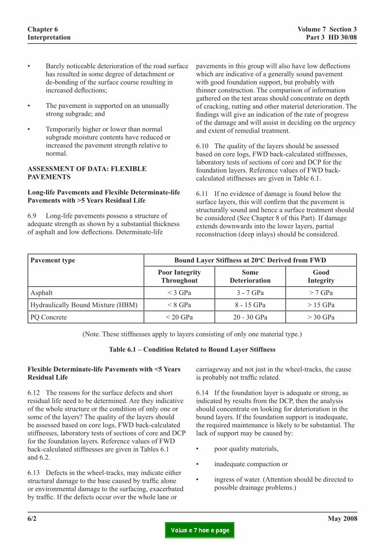
long-life pavements and flexible determinate-life pavements with >5 Years residual life
6.9 Long-life pavements possess a structure of adequate strength as shown by a substantial thickness of asphalt and low deflections. Determinate-life
pavement type Bound
poor integrithroughou
Asphalt < 3 GPa
Hydraulically Bound Mixture (HBM) < 8 GPa
PQ Concrete < 20 GPa
(Note. These stiffnesses apply to layers
table 6.1 – condition relate
flexible determinate-life pavements with <5 Years residual life
6.12 The reasons for the surface defects and short residual life need to be determined. Are they indicative of the whole structure or the condition of only one or some of the layers? The quality of the layers should be assessed based on core logs, FWD back-calculated stiffnesses, laboratory tests of sections of core and DCP for the foundation layers. Reference values of FWD back-calculated stiffnesses are given in Tables 6.1 and 6.2.
6.13 Defects in the wheel-tracks, may indicate either structural damage to the base caused by traffic alone or environmental damage to the surfacing, exacerbated by traffic. If the defects occur over the whole lane or
6/2
pavements in this group will also have low deflections which are indicative of a generally sound pavement with good foundation support, but probably with thinner construction. The comparison of information gathered on the test areas should concentrate on depth of cracking, rutting and other material deterioration. The findings will give an indication of the rate of progress of the damage and will assist in deciding on the urgency and extent of remedial treatment.
6.10 The quality of the layers should be assessed based on core logs, FWD back-calculated stiffnesses, laboratory tests of sections of core and DCP for the foundation layers. Reference values of FWD back-calculated stiffnesses are given in Table 6.1.
6.11 If no evidence of damage is found below the surface layers, this will confirm that the pavement is structurally sound and hence a surface treatment should be considered (See Chapter 8 of this Part). If damage extends downwards into the lower layers, partial reconstruction (deep inlays) should be considered.
layer stiffness at 20oc derived from fwd
ty t
some deterioration
good integrity
3 - 7 GPa > 7 GPa
8 - 15 GPa > 15 GPa
20 - 30 GPa > 30 GPa
consisting of only one material type.)
d to Bound layer stiffness
carriageway and not just in the wheel-tracks, the cause is probably not traffic related.
6.14 If the foundation layer is adequate or strong, as indicated by results from the DCP, then the analysis should concentrate on looking for deterioration in the bound layers. If the foundation support is inadequate, the required maintenance is likely to be substantial. The lack of support may be caused by:
• poor quality materials,
• inadequate compaction or
• ingress of water. (Attention should be directed to possible drainage problems.)
may 2008
volume 7 section 3 part 3 Hd 30/08
chapter 6 interpretation
6.15 Cores will indicate whether deterioration such as cracking, de-bonding of layers or stripping of the binder is present in one or more layers, all of which will affect road performance. Some of the weak or partially disintegrated materials found in older (>35 years) pavements, e.g. tar-bound slag, may have been in this state for a considerable length of time and the current performance of the pavement may not be adversely affected as a result. If there are no associated surface defects it should not be necessary to replace or overlay such weak materials. The cause of such poor strength is usually poor aggregate grading, high voids and low binder content.
6.16 A comparison of properties of materials taken from areas of minor or major surface defects may help to explain the reasons for the difference in performance.
6.17 If deterioration is confined to the surface layers, then it can be assumed that the lower intact pavement structure can be used with confidence as a basis for a surface maintenance treatment, including an overlay if a more significant extension of life is required.
6.18 Knowledge of the cause of the defects will provide a good basis for the design of structural maintenance. The primary factors to determine treatments are the condition of the layers and the causes of defects. Decisions on the type and timing of structural maintenance for all pavements will also be affected by consideration of skid resistance and the level of minor repairs, particularly patching and crack overbanding.
6.19 For dual carriageways, differences in the condition and deflection levels between different traffic lanes should be interpreted so that a comparison can be made when ascribing contributions to overall deterioration. This information also helps to optimise maintenance treatments across the carriageway width since not all lanes will necessarily justify the same approach.
additional factors applicable to flexible pavements with Hydraulically Bound Base
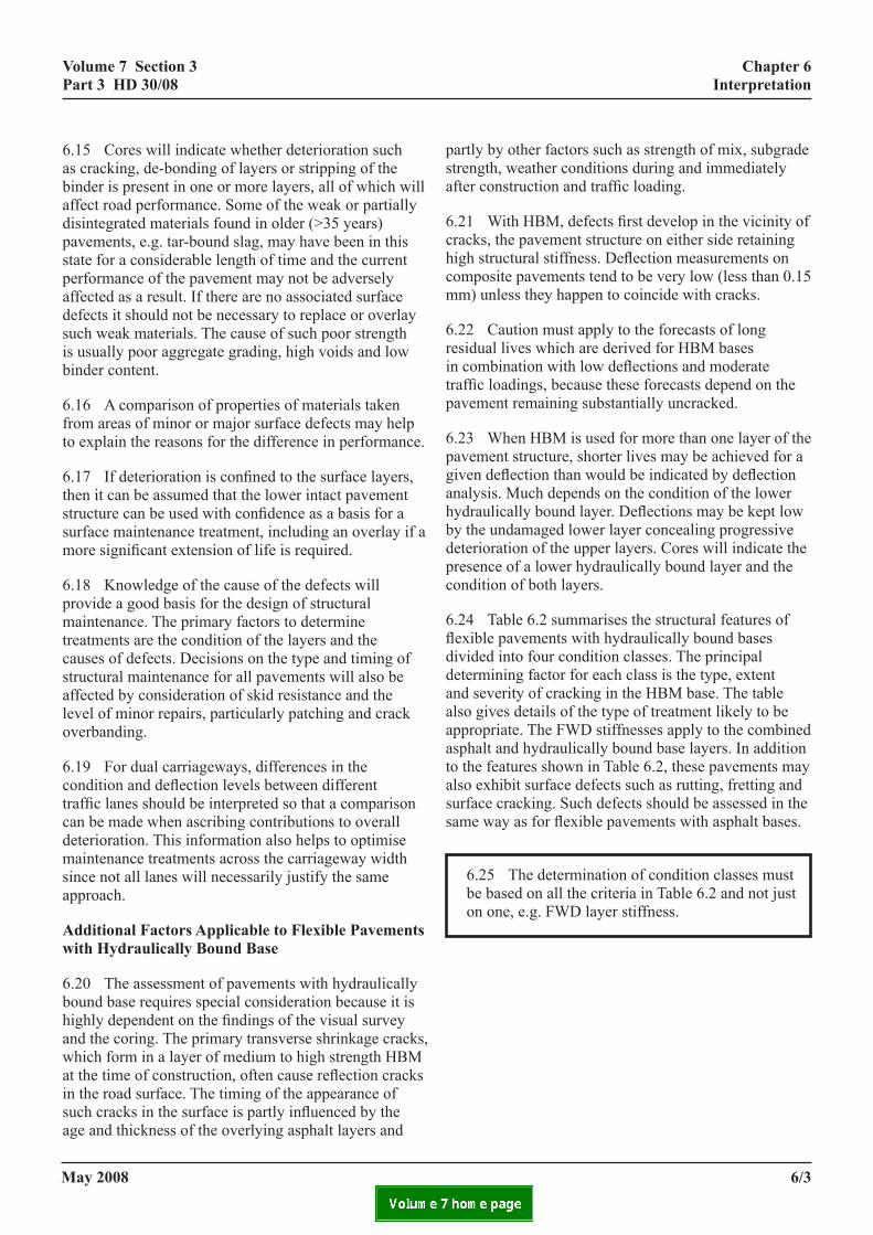
6.20 The assessment of pavements with hydraulically bound base requires special consideration because it is highly dependent on the findings of the visual survey and the coring. The primary transverse shrinkage cracks, which form in a layer of medium to high strength HBM at the time of construction, often cause reflection cracks in the road surface. The timing of the appearance of such cracks in the surface is partly influenced by the age and thickness of the overlying asphalt layers and
may 2008
partly by other factors such as strength of mix, subgrade strength, weather conditions during and immediately after construction and traffic loading.
6.21 With HBM, defects first develop in the vicinity of cracks, the pavement structure on either side retaining high structural stiffness. Deflection measurements on composite pavements tend to be very low (less than 0.15 mm) unless they happen to coincide with cracks.
6.22 Caution must apply to the forecasts of long residual lives which are derived for HBM bases in combination with low deflections and moderate traffic loadings, because these forecasts depend on the pavement remaining substantially uncracked.
6.23 When HBM is used for more than one layer of the pavement structure, shorter lives may be achieved for a given deflection than would be indicated by deflection analysis. Much depends on the condition of the lower hydraulically bound layer. Deflections may be kept low by the undamaged lower layer concealing progressive deterioration of the upper layers. Cores will indicate the presence of a lower hydraulically bound layer and the condition of both layers.
6.24 Table 6.2 summarises the structural features of flexible pavements with hydraulically bound bases divided into four condition classes. The principal determining factor for each class is the type, extent and severity of cracking in the HBM base. The table also gives details of the type of treatment likely to be appropriate. The FWD stiffnesses apply to the combined asphalt and hydraulically bound base layers. In addition to the features shown in Table 6.2, these pavements may also exhibit surface defects such as rutting, fretting and surface cracking. Such defects should be assessed in the same way as for flexible pavements with asphalt bases.
6.25 The determination of condition classes must be based on all the criteria in Table 6.2 and not just on one, e.g. FWD layer stiffness.
6/3

volume 7 section 3 part 3 Hd 30/08
chapter 6 interpretation
class a class B class c class d Visual Observation Surface cracking not
evident or confined to widely spaced minor transverse cracks unless associated with construction joints in the HBM.
Surface transverse cracking confined to left hand lane. No, or very minor, longitudinal cracking in the wheel-tracks.
Transverse and longitudinal cracking in the wheel-tracks are both evident with a medium or high frequency.
Transverse and longitudinal cracking in the wheel-tracks are both evident with a high frequency.
Deflection Consistent deflection measurements which are low in relation to foundation stiffness.
Measurements peak at regular intervals and the average is as expected in relation to foundation stiffness.
Measurements are variable and the average is as expected in relation to foundation stiffness
Measurements are high in relation to foundation stiffness.
Crack Severity (See below)
Transverse crack severity generally 1.
Transverse crack severity generally 2.
Transverse crack severity 2 or 3, longitudinal crack severity generally 1.
Transverse and longitudinal crack severity generally 3.
HBM strength ≥ 10MN/m2 ≥ 10MN/m2 < 10MN/m2 < 10MN/m2 Cores Consistent sound HBM
with no wide cracks. Some occasional cracking in HBM but material generally sound.
Wide longitudinal cracks but material between cracks is sound.
Wide cracks for the full depth of some cores.
FWD - mean pavement layer stiffness modulus (< 20oC)
Consistent results >10GPa with a few individual results below 7GPa
>10GPa with some individual results below 7GPa
Variable results average >10GPa with successive results below 7GPa
<7GPa
Probable CBM condition • Little deterioration beyond initial transverse cracking due to early shrinkage and thermal warping, with good load transfer across transverse cracks.
• Deterioration has gone beyond initial transverse cracking. HBM slabs are large with movement at transverse cracks.
• Longitudinal cracking is slight or absent, with good load transfer across cracks.
• HBM slabs are large with significant movement at transverse cracks.
• Longitudinal cracking is present.
• HBM slabs are small, probably < 4m maximum dimension.
• Multiple transverse and longitudinal cracks with poor load transfer.
Implications for strengthening
• Structure has very little deterioration and pavement may be indeterminate with potential traffic capacity between 20 and 80 msa.
• If less than about 10 years old and determinate, it may be worthwhile overlaying to achieve an indeterminate pavement design.
• Structure has some deterioration and so cannot be assessed for an indeterminate design.
• See Chapter 8 overlay design procedure.
• Treat severity 2 cracks by trenching and replacing with asphalt.
• See Chapter 8 for overlay design procedure.
• Treat transverse cracks of severity 2 and 3 by trenching and replacing with asphalt.
• Locally reconstruct areas of badly cracked HBM with asphalt.
• Pavement will need to be removed to top of subbase, or lower, and reconstructed. The HBM will continue to deteriorate towards the condition of an unbound granular layer.
• Consideration should be given to retaining the pavement until the amount of patching becomes unacceptable.
• Thick overlay may be an alternative.
Crack Severity Ratings: 1: Widely spaced cracks (>10m), generally ≤ 0.5mm wide, without fretting, and no evidence of vertical movement. 2: Regularly spaced cracks (5 to 10m), generally ≤1.0mm wide, with some fretting, and evidence of horizontal and vertical movement. 3: Regularly and irregularly spaced cracks, generally >1.0mm wide, with some fretting, and evidence of horizontal and vertical movement.
table 6.2 – assessment of treatment of flexible pavements with Hydraulically Bound Base
may 20086/4

volume 7 section 3 part 3 Hd 30/08
chapter 6 interpretation
assessment of data: rigid pavements
6.26 Similar guidelines to those for flexible pavements should be adopted when examining the data for rigid pavements. An indication of the effects on performance of slab thicknesses and the strength of underlying layers for rigid pavements may be determined using HD 26 (DMRB 7.2.3). When dealing with jointed pavement, special emphasis should be placed on the condition of the joints, but the same careful analysis of the condition of the foundation is necessary.
6.27 The adequacy of the Load Transfer Efficiency (LTE) of joints or cracks can be assessed by Falling Weight Deflectometer measurements as described in HD 29 (DMRB 7.3.2). Joints or cracks with perfect load transfer should give a transfer efficiency of just under 100%. Defining a general LTE percentage above which the joints or cracks may be considered satisfactory is very difficult as it will vary from site to site and depend on temperatures through the depth of the slab at the time of testing.
6.28 Benchmark values of LTE to indicate acceptable crack or joint performance must be established for each site by comparison with visual condition information and coring data. The absolute values of the deflections must also be taken into account as low LTE values based on low absolute deflections may have little significance.
6.29 The Concrete Pavement Maintenance Manual (2001) gives further information on the assessment and interpretation of rigid pavement defects.
6.30 The options for maintenance will depend on the condition of the joints, the state of the concrete and the condition of the foundation. Maintenance of concrete pavements is considered in full in HD32 (DMRB 7.4.2).
falling weigHt deflectometer (fwd)
reference stiffness values
6.31 Typical values of layer stiffness related to likely condition are given in Tables 6.1 and 6.2. Conclusions regarding layer weaknesses must be supported by more than one type of observation or measurement. Layer stiffnesses must always be checked for correlation with pavement visual condition, the layer condition evident in cores, Deflectograph results and any laboratory
6tmb(c
6o
6ictowft
6abfltlbepseo
may 2008
test results. Materials which fall in the ‘Some deterioration’ stiffness category are not necessarily unserviceable. Depending on the other indicators, they could remain in the pavement with or without further strengthening.
.32 The reference stiffness values in Table 6.2 apply o pavement layers consisting of only one type of aterial. Flexible pavements with hydraulically bound
ase may also be analysed with all the bound layers asphalt and HBM) combined as a single layer and ompared to the stiffness values given in Table 6.1.
.33 Some of the factors that influence layer stiffness f various materials are given in Table 6.3.
material stiffness decreases stiffness increasesAsphalt High voids
Cracking Layer debonding Stripping
Low voids Binder-hardening
Concrete Joint nearby Cracking Debonding Poor compaction
-
Granular High moisture Clay contamination
Low moisture Natural-cementing
Subgrade High moisture Low moisture
table 6.3 – factors affecting layer stiffness
.34 Although FWD back-analysis can provide an ndication of the layer stiffness, core or DCP data (in the ase of unbound material) will be needed in all cases o determine the cause of any low values. Comparisons f the layer stiffness derived from measurements made here the material is relatively untrafficked, with those
rom the line of the wheel-track can indicate whether he weakness is due to trafficking or not.
.35 For the foundation layers of existing pavements, layer stiffness of at least 0.1GPa (=100MPa), has een found to be associated with good performance of exible pavements with asphalt base. It is also thought
o be a reasonable criterion for the unbound foundation ayers of flexible pavements with hydraulically bound ase and rigid pavements. More than 100MPa would be xpected for hydraulically bound subbase below a rigid avement. Large variations in the measured foundation upport are usually associated with a change in drainage fficiency, subbase/capping layer or subgrade material r a construction change such as a cut/fill line.
6/5

volume 7 section 3 part 3 Hd 30/08
chapter 6 interpretation
comparing fwd stiffnesses with itsm
6.36 There is a strong association between Indirect Tensile Stiffness Modulus (ITSM) values and asphalt layer stiffnesses estimated from FWD back-analysis. As the stiffness of asphalt is loading-time dependent, the shorter pulse of the FWD results in stiffnesses greater than ITSM values. As an approximate guide, ITSM values at 20oC should be multiplied by 1.5 when comparing with FWD-derived asphalt layer stiffnesses at 20oC. However, depending on the type and age of the asphalt material this factor has been found to vary between 1.0 and 2.4. Therefore, although the ITSM values can indicate the in situ layer stiffness, core data will be needed in all cases to determine the causes of any low values.
report
6.37 The findings and recommendations of the investigation into the causes of deterioration of all types of pavements must be stated in a report. This should also include summaries of the Network survey data and the results from the Scheme survey investigation in graphical or tabular format as appropriate.
may 20086/6

volume 7 section 3 part 3 Hd 30/08
chapter 7 treatment design
7. treatment design
introduction
7.1 This Chapter gives advice on treatment options for flexible and rigid pavements, including surface and structural maintenance. The design of overlay strengthening measures is covered in detail and includes advice on the factors to be considered in order to arrive at an appropriate and economic maintenance solution. Advice on the application of treatments is given in HD 31 (DMRB 7.4.1) for flexible pavements and HD 32 (DMRB 7.4.2) for rigid pavements. The surfacing materials permitted by the Overseeing Organisations, for use on both flexible and rigid pavements, are given in HD 36 (DMRB 7.5.1).
procedure
7.2 The decision-making process for the selection of an appropriate maintenance treatment for flexible pavements with asphalt base is illustrated as a flowchart in Figure 7.1. The process for flexible pavements with hydraulically bound bases is given later in this chapter. The following paragraphs follow the flowchart and explain what is involved at each stage for a flexible pavement with asphalt base. Similar principles apply to rigid pavements.
Necessity of Treatment and Whole Life Costs
7.3 The choice of treatment must be based on safety, serviceability, financial, environmental and traffic disruption considerations as well as on a purely technical assessment. Various treatment options should be considered. For the HA network this should consider Do Nothing, Do Minimum and Do Something options over the next five year plan. Treatments for Do Something options may be only locally required and may vary from lane to lane. A Whole Life Cost analysis should be used when comparing the costs of different options. For the HA network the SWEEP system (part of HAPMS) is used for this purpose.
7.4 The other Overseeing Organisations use several other systems including WDMPMS, SAS and UKPMS. Further information on which system should be used on a particular network should be obtained from the relevant Overseeing Organisation.
may 2008
Surface Damage
7.5 Where deterioration is found only in the surface or binder course (approximately the top 100mm of the pavement) and there is an adequate total pavement thickness, no strengthening is normally required. A surface treatment or inlay would be suitable treatments depending on the extent of deterioration and how far it extends downwards into the surfacing layers. Crack sealing should be considered for small widely scattered areas of cracking. Where permitted by the Overseeing Organisation, a surface dressing will be more appropriate to treat areas of more extensive shallow cracking or to maintain a skid resistant surface.
7.6 Inlays, involving the replacement of the surface course and possibly the binder course, may be necessary to remove more deeply cracked, fretted or rutted surfacings to prevent these defects affecting the lower layers of the pavement and its structural condition or, in the case of cracks, from reflecting through into the new surfacing material.
Structural Deterioration
7.7 If the assessment process concludes that strengthening is required because of say, deteriorated or weak material deep within the pavement or a lack of pavement thickness, the following options should be considered: overlay, partial reconstruction or full reconstruction. Overlays and possibly the other options may raise the finished road surface relative to existing levels. Where this is unacceptable, the use of stiff EME2 asphalt as the new structural material can provide substantial strengthening for less thickness compared to traditional materials.
7.8 On financial grounds, it is preferable that overlays to pavements should be applied while its structure is still essentially intact. If the existing surfacing shows signs of surface deterioration, which will usually be the case, it is generally desirable to plane the surface to a depth of 15 to 20mm before overlaying, particularly where the overlay is less than 100mm. This is to remove material with hardened bitumen and provide a sound, uncracked surface to which the new asphalt can firmly bond. Where the existing surfacing is cracked or damaged to a depth greater than 20mm, the defective material must be removed and replaced with new material before the overlay is applied. Damaged or sub-standard asphalt
7/1

volume 7 section 3 part 3 Hd 30/08
chapter 7 treatment design
ns for Flexible Pavements with Asphalt Base
layers lower in the pavement could be left in place depending on the degree of damage and the depth relative to the new surface.
figure 7.1 – maintenance treatment optio
Volume 7 Section 3 Part 3 HD 30/08
Figure 7.1 Maintenance Treatment Optio
Can a lowtreatment bedelay streng
Is overlafeasible
Are foundation layers giving
adequate support?
Is drainage effective?
N
YES
YES N
NO
NO
YES N
START Surface defects evident
Defects conto surface l
Is strengthening required?
NO
RECTIFY DRAINAGE See HA 44
(DMRB 4.1.1)
7/2
January 2008
7.10 Once excessive deterioration has taken place so aeconomically desirable to delay reconstruction work as
7.9 Where tar-bound materials are encountered it is desirable to leave these in situ, even if they are not in very good condition, to avoid the complications and costs of the proper disposal of this material.
ns for flexible pavements with asphalt Base
Chapter 7 Treatment Design
PLANE OFF OR PATCH ANY DAMAGED
MATERIAL
RECONSTRUCT
FOUNDATION AND BOUND LAYERS
PARTIAL OR FULL RECONSTRUCTION
(Ideal depth of reconstruction may have to be reduced to limit traffic
disruption – monitoring will then be required.)
PATCH LOCALLY, APPLY LOW COST
SURFACE TREATMENT - MONITOR REGULARLY
See HD 31 (DMRB 7.4.1) cost used to thening?
y ?
O
YES
YES
O
O
RESURFACE (INLAY) AREAS OF SIGNIFICANT
SURFACE DEFECTS WITH PERMITTED
MATERIAL - See HD 36 (DMRB 7.5.1)
fined ayers?
YES
PARTIAL RECONSTRUCTION
(INLAY TO DEPTH OF DEFECTS)
may 2008
7/3
s to exclude overlaying as a viable option, then it is long as possible, to gain maximum use from materials

volume 7 section 3 part 3 Hd 30/08
chapter 7 treatment design
7.10 Once excessive deterioration has taken place so as to exclude overlaying as a viable option, then it is economically desirable to delay reconstruction work as long as possible, to gain maximum use from materials which will have to be replaced. Clearly, safety, legal and environmental considerations place a limit on such delays as does the rising quantity and cost of day to day minor maintenance.
7.11 The exception to this delaying of reconstruction work is where local reconstruction would be likely to forestall the spread of deterioration significantly. This also applies to concrete pavements where longitudinal cracks, once initiated, can propagate relatively rapidly along the carriageway.
Feasibility of Overlay
7.12 There are some instances where an overlay is not economically feasible or has to be of limited thickness. This may be due to the constraints of overbridge clearances, parapet and safety fence heights, kerbs, etc. Such restrictions should be checked at an early stage of the evaluation process. The necessary headroom must be maintained under all gantries and overbridges. The possibility of overloading at underbridges and adjacent to retaining walls must also be considered. Allowance must be made for expansion joints (if concrete overlays are used), kerbing and drainage at under bridges. Heights of copings and parapet walls will also need consideration adjacent to retaining walls and at under bridges. Safety barrier heights will need to be examined and the barrier adjusted or re-erected if necessary.
7.13 If an overlay is to be carried out then the original pavement will be retained together with all its defects. These defects have to be allowed for in overlay design. If a serious weakness exists in one of the layers, then it may be economic to reconstruct down to and including that layer, rather than to apply a relatively thick overlay. If a layer is found to be in the process of rapid deterioration which cannot be halted, then reconstruction may be preferable.
7.14 Where some of the lanes of a carriageway have substantial remaining life and do not require treatment, the additional cost of a structurally unnecessary overlay over satisfactory lanes will have to be considered. It may be cheaper to partially or fully reconstruct the nearside lane.
may 2008
Partial Reconstruction (Inlays) or Full Reconstruction (All bound layers and possibly the foundation layers replaced)
7.15 Where reconstruction, partial or full, is required, then it is generally necessary to take out only those layers which are defective, i.e. if the granular layers are satisfactory, they should normally be retained. As much as possible of the sound, existing material should be retained. This will not only save materials and expenditure, but also provide a firm basis for the new layers. Retained layers should be left undisturbed. However, the dual constraints of finished pavement level and design thickness may require the removal of some sound material. In the case of flexible pavements with hydraulically bound base, consideration should be given to retaining any severely deteriorated HBM and using it as the foundation for a reconstructed pavement. In certain cases, cracking and seating of an existing hydraulically bound base may also be cost effective (see HD 32 (DMRB 7.4.2)).
7.16 In some circumstances it may not be possible to carry out the full depth of partial or full reconstruction indicated by the survey and investigation data, because of the excessive traffic disruption that this will cause. This is likely to arise where traffic levels are high, in an urban or residential environment (which may preclude or limit night working) and where there is a lack of suitable diversions. In these conditions lesser scale works may have to be carried out, despite the knowledge that this is not a lasting solution and further major treatments may be required in 5 to 10 years rather than 10 to 15 years. More regular condition monitoring will be required for road lengths treated in this way.
Drainage
7.17 Drainage failures can lead to significant weakening of the unbound layers, as well as the subgrade. This reduces the support to the bound layers, causing failure of the pavement as a whole. If drainage faults are found, it is essential that they are rectified as soon as possible and action taken to prevent recurrence. The extent and degree of strengthening should only be finalized after the effect of the drainage measures has been assessed. Reference should be made to HA 44 (DMRB 4.1.1) for further detailed advice.
surface treatment
7.18 Timely surface treatment can be effective in halting deterioration before serious damage to the remaining structure takes place. If it is timed to coincide with a need for improvement to surface texture or
7/3

volume 7 section 3 part 3 Hd 30/08
chapter 7 treatment design
skidding resistance, then it is economically even more attractive. Details of surface treatments are given in HD 31 (DMRB 7.4.1).
asphalt overlay design
7.19 For flexible pavements, strengthening by overlay and/or partial reconstruction is normally designed to extend the life for a further 20 years or with a treatment agreed with the Overseeing Organisation appropriate to the condition of the existing pavement.
7.20 For flexible pavements with asphalt base, overlays may also comprise the additional thickness of material required to convert a determinate life pavement (with low deflections) into a long-life pavement, i.e. an ‘Upgradeable to LLP’ pavement as shown in Figure 2.1 of this Part.
7.21 Several options for strengthening by overlay may be considered. For flexible pavements, a first indication of the range of thicknesses of material required along the site may be obtained from Deflectograph data, processed using either PANDEF or HAPMS. The 85th percentile deflection applicable to each 100m length should be used for this purpose, see HD 29 (DMRB 7.3.2).
7.22 Overlay design must not be based on deflection results alone. The analysis of Deflectograph data is a starting point, not an end point as Deflectograph analysis does not take into account all factors relating to pavement performance. There must be confirmatory evidence of surface defects and material condition.
7.23 Another approach to overlay design is to compare the thickness of the existing pavement structure with that required for new construction designed to carry both past and future traffic in accordance with HD 26 (DMRB 7.2.3); the difference in thickness is an estimate of the necessary overlay. Allowance should be made for any deterioration or initial deficiencies, as well as the varying materials in the existing pavement.
Asphalt Overlay to Flexible Pavements
7.24 For flexible pavements, overlay design thicknesses are based on the use of traditional Dense Bitumen Macadam (DBM125) material. This type of asphalt is now designated “AC 20 dense bin 100/150 rec” or “AC 32 dense base 100/150 rec” as defined in BS EN 13108, depending on the required thicknesses.
7/4
Guidance in the application on the use of the new asphalt mixtures is given in PD 6691:2007.
7.25 If stiffer asphalt materials specified in BS EN 13108:2006 are used, then some reduction in overlay thickness is possible, except in the case of flexible pavements with hydraulically bound base. An assessment of the potential savings in thickness can be gained from a comparison of the recommendations given in HD 26 (DMRB 7.2.3) for the design of new roads. (The traditional asphalt designations used in HD 26 will have to be matched to the new designations given in BS EN 13108.)
7.26 Where investigations indicate that there are areas of localised, more severely deteriorated material within a length otherwise identified for overlay, it is recommended that full or partial depth reconstruction is carried out in those areas prior to overlaying to ensure as uniform a standard of road as possible.
7.27 Guidance on treatments for flexible pavements with hydraulically bound bases is given in the categorisation described in Chapter 6, Table 6.2 of this Part and Figure 7.2 of TRL Report TRL 657 (2006). Pavements in Class A require no action except where it is desirable to increase the original design life of the road. Figure 7.1 of this Part may be used to design an overlay for Category 1 pavements to produce an indeterminate life. Some flexible pavements with hydraulically bound bases which have thick asphalt cover, and cracked, seated and overlaid pavements may be closer in performance to a flexible pavement with a strong asphalt base. This should be taken into account both when analysing deflection data and when considering strengthening options. For example, the Deflectograph processing algorithms in HAPMS and PANDEF assume that flexible pavements with hydraulically bound bases and more than 300mm of asphalt can be treated as flexible pavements.
7.28 Flexible pavements with hydraulically bound bases in Classes B and C of Table 6.2 of this Part, generally require an overlay, but are also likely to need local reconstruction at severe cracks in the hydraulically bound material. The treatment selection chart in TRL 657 may be used to decide the appropriate treatment. For flexible pavements with hydraulically bound bases, an asphalt overlay provides additional thermal insulation to the HBM layer, as well as preventing ingress of water to the HBM layer and the foundation.
may 2008
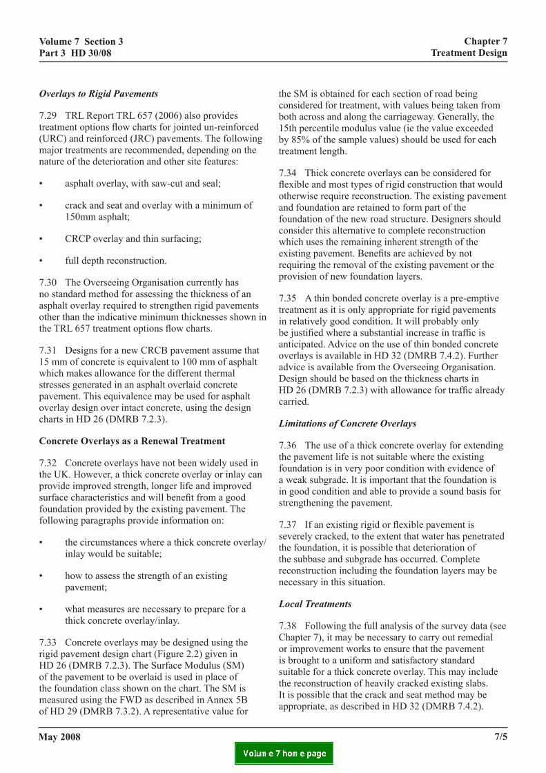
volume 7 section 3 part 3 Hd 30/08
chapter 7 treatment design
Overlays to Rigid Pavements
7.29 TRL Report TRL 657 (2006) also provides treatment options flow charts for jointed un-reinforced (URC) and reinforced (JRC) pavements. The following major treatments are recommended, depending on the nature of the deterioration and other site features:
• asphalt overlay, with saw-cut and seal;
• crack and seat and overlay with a minimum of 150mm asphalt;
• CRCP overlay and thin surfacing;
• full depth reconstruction.
7.30 The Overseeing Organisation currently has no standard method for assessing the thickness of an asphalt overlay required to strengthen rigid pavements other than the indicative minimum thicknesses shown in the TRL 657 treatment options flow charts.
7.31 Designs for a new CRCB pavement assume that 15 mm of concrete is equivalent to 100 mm of asphalt which makes allowance for the different thermal stresses generated in an asphalt overlaid concrete pavement. This equivalence may be used for asphalt overlay design over intact concrete, using the design charts in HD 26 (DMRB 7.2.3).
concrete overlays as a renewal treatment
7.32 Concrete overlays have not been widely used in the UK. However, a thick concrete overlay or inlay can provide improved strength, longer life and improved surface characteristics and will benefit from a good foundation provided by the existing pavement. The following paragraphs provide information on:
• the circumstances where a thick concrete overlay/inlay would be suitable;
• how to assess the strength of an existing pavement;
• what measures are necessary to prepare for a thick concrete overlay/inlay.
7.33 Concrete overlays may be designed using the rigid pavement design chart (Figure 2.2) given in HD 26 (DMRB 7.2.3). The Surface Modulus (SM) of the pavement to be overlaid is used in place of the foundation class shown on the chart. The SM is measured using the FWD as described in Annex 5B of HD 29 (DMRB 7.3.2). A representative value for
tcb1bt
7floafcwerp
7tibaoaDHc
L
7tfais
7sttrn
L
7CoistIa
may 2008
he SM is obtained for each section of road being onsidered for treatment, with values being taken from oth across and along the carriageway. Generally, the 5th percentile modulus value (ie the value exceeded y 85% of the sample values) should be used for each reatment length.
.34 Thick concrete overlays can be considered for exible and most types of rigid construction that would therwise require reconstruction. The existing pavement nd foundation are retained to form part of the oundation of the new road structure. Designers should onsider this alternative to complete reconstruction hich uses the remaining inherent strength of the
xisting pavement. Benefits are achieved by not equiring the removal of the existing pavement or the rovision of new foundation layers.
.35 A thin bonded concrete overlay is a pre-emptive reatment as it is only appropriate for rigid pavements n relatively good condition. It will probably only e justified where a substantial increase in traffic is nticipated. Advice on the use of thin bonded concrete verlays is available in HD 32 (DMRB 7.4.2). Further dvice is available from the Overseeing Organisation. esign should be based on the thickness charts in D 26 (DMRB 7.2.3) with allowance for traffic already
arried.
imitations of Concrete Overlays
.36 The use of a thick concrete overlay for extending he pavement life is not suitable where the existing oundation is in very poor condition with evidence of weak subgrade. It is important that the foundation is n good condition and able to provide a sound basis for trengthening the pavement.
.37 If an existing rigid or flexible pavement is everely cracked, to the extent that water has penetrated he foundation, it is possible that deterioration of he subbase and subgrade has occurred. Complete econstruction including the foundation layers may be ecessary in this situation.
ocal Treatments
.38 Following the full analysis of the survey data (see hapter 7), it may be necessary to carry out remedial r improvement works to ensure that the pavement s brought to a uniform and satisfactory standard uitable for a thick concrete overlay. This may include he reconstruction of heavily cracked existing slabs. t is possible that the crack and seat method may be ppropriate, as described in HD 32 (DMRB 7.4.2).
7/5

volume 7 section 3 part 3 Hd 30/08
chapter 7 treatment design
7.39 If the existing pavement is of rigid construction and there is robust evidence of voids beneath the slab then under slab grouting (with lifting if necessary) should be considered. For further advice refer to HD 32 (DMRB 7.4.2). Where the existing pavement is of flexible construction, any large cracks should be treated to ensure a sound structure and surface suitable for an overlay. Advice on the treatment of cracks in flexible surfacing is available in HD 31 (DMRB 7.4.1.4). It may also be necessary to plane off the upper layers if they have become seriously weakened.
7pr
E
7ttmTa
overlay material
e
flexible urcJrc
CRCP None Not recomm
CRCB None Separatmembra
table 7.1 – preparation treatm
7.42 For each situation where a thick concrete overlay is being considered, it is important that full allowance is made for all thermal movements of the pavement. Overlay slabs should be constructed to the requirements of the Specification and the Highway Construction Details (MCHW 1, 2 and 3).
7.43 If a separation membrane is required, the Overseeing Organisation’s requirements for such membranes are contained in the Specification: MCHW 1, Series 1000.
reconstruction design
7.44 Strengthening by reconstruction involves the removal of a certain depth of the structural layers of the existing pavement and replacing these with a thickness of new or recycled material. It could involve replacement of some layers only – partial reconstruction. Alternatively it could involve total reconstruction and the replacement of some of the subgrade with fill material – full reconstruction. The degree to which existing materials should be replaced generally depends upon the degree of deterioration of each of the layers.
Structural Layer Replacement
7.45 If the main structural (bound) pavement layers, whether asphalt or concrete, are in a seriously
dosdWrFtp
7brtltiseTrer
7osocd
7/6
.40 For both flexible and rigid pavements, all otholes, large irregularities and deep spalls should be emedied before overlaying.
xisting Surfaces
.41 Depending on the existing surface material and he design of the thick overlay slab, certain preparation reatments may be necessary. Use of a regulating layer ay be required, either asphalt or concrete. able 7.1 sets out the various options that are possible nd indicates if any surface treatment is required.
xisting pavement
crcp crcB
ended None None
ion ne
None None
ents for concrete overlays
eteriorated condition, then replacement rather than verlaying may be the most economical solution. In ome instances, only partial replacement is necessary, epending on the depth to which defects are present. herever possible, the existing subbase should be
etained to provide protection to the underlying layer. or flexible pavements with hydraulically bound base,
he HBM layer should be retained if it is capable of roviding long-term support.
.46 Flexible pavements with hydraulically ound base in Class D of Table 6.2 will need to be econstructed because the HBM will have deteriorated o small slabs with poor load transfer. Deterioration is ikely to continue until the HBM becomes little more han a granular subbase. In such cases, particularly f the asphalt is thick and in reasonable condition, ome years of useful life may be obtained from the xisting pavement before reconstruction is carried out. he importance of the route and the consequences of
egular small scale maintenance interventions will be ssential inputs into the decision as to the timing of econstruction.
.47 The design of the reconstruction may be carried ut using the charts in HD 26 (DMRB 7.2.3). The tiffness of the foundation (the remainder of pavement nce the layers to be replaced have been removed) an be taken into account and classed as 1, 2, 3 or 4 as efined in HD 26 (DMRB 7.2.3).
may 2008

volume 7 section 3 part 3 Hd 30/08
chapter 7 treatment design
Whole Pavement Replacement
7.48 If the subbase is considered inadequate (e.g. low CBR, contamination, etc) then it will require replacement. The reconstruction required can be designed wholly in accordance with HD 25 (DMRB 7.2.2) and HD 26 (DMRB 7.2.3). The subgrade then requires assessment as to whether it provides a satisfactory platform for this reconstruction. If not, then capping may also be required.
7.49 Where the subbase is considered satisfactory and the stiffness modulus provided by the foundation as a whole is adequate, then there is no need to excavate, even if the subgrade itself is of low CBR. This is because the provision of capping in the construction of new roads is primarily to enable the subbase and upper layers to be adequately laid and compacted, and to ensure that no damage to the subgrade occurs as a result of construction phase trafficking.
may 2008 7/7

volume 7 section 3 part 3 Hd 30/08
grapHY
chapter 8 references and Bibliography
8. references and BiBlio
references
1. design manual for roads and Bridges (dmrB)
HD 23 – General Information (DMRB 7.1.1)
HD 24 – Traffic Assessment (DMRB 7.2.1)
HD 25 – Foundations (DMRB 7.2.2)
HD 26 – Pavement Design (DMRB 7.2.3)
HD 28 – Skidding Resistance (DMRB 7.3.1)
HD 29 – Data for Pavement Assessment (DMRB 7.3.2)
HD 31 – Maintenance of Bituminous Roads (DMRB 7.4.1)
HD 32 – Maintenance of Concrete Roads (DMRB 7.4.2)
HD 36 – Surfacing Materials for New and Maintenance Construction (DMRB 7.5.1)
HD 41 – Maintenance of Highway Geotechnical Assets (DMRB 4.1.3)
HA 44 – Earthworks: Design and Preparation of Contract Documents (DMRB 4.1.1)
TD 19 – Requirement for Road Restraint Systems (DMRB 2.2.8)
2. manual of contract documents for Highway works (mcHw)
Volume 1: Specification for Highway Works
Volume 2: Notes for Guidance on the Specification for Highway Works
Volume 3: Highway Construction Details
3.
4.
5.
may 2008
transport research laboratory documents (trl)
TRL 250; Nunn, M.E., Brown, A., Weston, D. and Nicholls, J.C., ‘Design of long-life flexible pavements for heavy traffic’, TRL, 1997
TRL 657; Coley, C. and Carswell, I., ‘Improved design of overlay treatments to concrete pavements. Final report on the monitoring of trials and schemes’, TRL, 2006
British standards
BS EN 12697-26:2004 Bituminous mixtures. Test methods for hot mix asphalt. Stiffness
BS EN 13108 Various Parts: 2005 and 2006 Bituminous mixtures. Material specifications
PD 6691:2007 Guidance on the use of BS EN 13108 Bituminous mixtures – Material specifications
statutory publications
Health and Safety at Work Act (1974)
Health and Safety at Work (Northern Ireland) Order 1979
Management of Health and Safety at Work Regulations (1999)
Management of Health and Safety at Work Regulations Statutory Rules of Northern Ireland, 2000 No 87
Construction (Design and Management) Regulations, Statutory Instrument 2007 No. 320
Safety at Street Works and Road Works – A Code of Practice, Department for Transport, 2002
Traffic Signs Manual Chapter 8, Department for Transport, 2006
Construction (Design and Management) Regulations (Northern Ireland), Statutory Rules of Northern Ireland, 2007 No. 291
8/1

volume 7 section 3 part 3 Hd 30/08
chapter 8 references and Bibliography
6. other publications
Network Management Manual, Highways Agency
National Assembly for Wales Trunk Road Manual, National Assembly for Wales Transport Directorate
Concrete Pavement Maintenance Manual (2001), Highways Agency and Britpave (published by the Concrete Society)
Bibliography
LR1132; Powell, W.D., Potter, J.F., Mayhew, H.C. and Nunn, M.E., ‘The Structural Design of Bituminous Roads’, TRRL, 1984
RR87; Mayhew, H.C. and Harding, H.M., ‘Thickness Design of Concrete Roads’, TRRL, 1987
may 20088/2

may 2008
volume 7 section 3 part 3 Hd 30/08
9. enQuiries
All technical enquiries or comments on this Standard should be sent in writing as appropriate to:
Chief Highway Engineer The Highways Agency 123 Buckingham Palace Road London G CLARKE SW1W 9HA Chief Highway Engineer
Director, Major Transport Infrastructure Projects Transport Scotland 8th Floor, Buchanan House 58 Port Dundas Road A C McLAUGHLIN Glasgow Director, Major Transport Infrastructure G4 0HF Projects
Chief Highway Engineer Transport Wales Welsh Assembly Government Cathays Parks M J A PARKER Cardiff Chief Highway Engineer CF10 3NQ Transport Wales
Director of Engineering The Department for Regional Development Roads Service Clarence Court 10-18 Adelaide Street R J M CAIRNS Belfast BT2 8GB Director of Engineering
9/1
chapter 9 enquiries