dmrb volume 8 section 2 part 1 - ta 58/92 - traffic … 58-92 traffic signs and road markings... ·...
TRANSCRIPT

Traffic Signs and Road Markings
for Lane Gains and Lane Drops
on All-Purpose Dual Carriageway
and Motorway Trunk Roads
Summary: This Advice Note recommends the type of traffic signs and road markings to be used atlocations where traffic lanes are gained or dropped in either permanent or temporarysituations.
This Advice Note provides advice on specification requirements for use in publicpurchasing contracts. It does not lay down legislative requirements for products andmaterial used in highway construction in the United Kingdom.
THE HIGHWAYS AGENCY TA 58/92
THE SCOTTISH OFFICE DEVELOPMENT DEPARTMENT
Incorporating Ammendment
No. 1, dated April 1994
THE WELSH OFFICE
Y SWYDDFA GYMREIG
THE DEPARTMENT OF
THE ENVIRONMENT FOR NORTHERN IRELAND

Volume 8 Section 2Part 1 TA 58/92 Registration of Amendments
ELECTRONIC COPY - NOT FOR USE OUTSIDE THE AGENCY
June 1992 PAPER COPIES OF THIS ELECTRONIC DOCUMENT ARE UNCONTROLLED
REGISTRATION OF AMENDMENTS
Amend Page No Signature & Date of Amend Page No Signature & Date ofNo incorporation of No incorporation of
amendments amendments

Volume 8 Section 2Registration of Amendments Part 1 TA 58/92
ELECTRONIC COPY - NOT FOR USE OUTSIDE THE AGENCY
PAPER COPIES OF THIS ELECTRONIC DOCUMENT ARE UNCONTROLLED June 1992
REGISTRATION OF AMENDMENTS
Amend Page No Signature & Date of Amend Page No Signature & Date ofNo incorporation of No incorporation of
amendments amendments

DESIGN MANUAL FOR ROADS AND BRIDGES
ELECTRONIC COPY - NOT FOR USE OUTSIDE THE AGENCY
June 1992 PAPER COPIES OF THIS ELECTRONIC DOCUMENT ARE UNCONTROLLED
VOLUME 8 TRAFFIC SIGNS ANDLIGHTING
SECTION 2 TRAFFIC SIGNS ANDROAD MARKINGS
PART 1
TA 58/92
TRAFFIC SIGNS AND ROADMARKINGS FOR LANE GAINS ANDLANE DROPS ON ALL-PURPOSEDUAL CARRIAGEWAYS ANDMOTORWAY TRUNK ROADS
Contents
Chapter
1. Introduction
2. Permanent Lane Gain
3. Permanent Lane Drop
4. Temporary Lane Gain/Lane Drop
5. General Requirements
6. References
7. Enquiries
Appendix 1 Permanent SignsAppendix 2 Temporary Signs for RoadworksAppendix 3 TablesAppendix 4 Diagrammatic Road Layouts

Volume 8 Section 2 Chapter 1Part 1 TA 58/92 Introduction
1. INTRODUCTION
s.
n
eB
may, for
,
t
ld
f
General Sc
1.1 There are two main types of situation wheretraffic lanes are gained or dropped:
i. at junctions where traffic streams cometogether or separate with an associated gain orloss of one or more traffic lanes;
ii. on lengths of carriageway where awidening or narrowing occurs involving theaddition or loss of one or more full widthtraffic lanes. (In general, this will apply totemporary situations only - see 3.5.)
1.2 The variation of the number of carriagewaylanes over specific sections of route to meet particulartraffic management demands brings with it differentsigning needs beyond those covered in existing advice.
1.3 Chapter 4 of the Traffic Signs Manual (1986)[paragraphs 4.13 and 4.14] (Ref 1) deals with WarningSigns for use at junctions where the joining stream oftraffic may be required to concede priority to the"through" traffic stream.
1.4 The situation where lanes are gained ordropped is not as straightforward. A need has beenidentified for additional new traffic signs to be providedat these locations to ensure that drivers understand theroad layout, to prepare them for the traffic movementsthey are likely to encounter and manoeuvres they willhave to make.
1.5 Where drawings and specifications for signsdescribed in this Advice Note require that materials orproducts shall comply with a British Standard, theserequirements shall be satisfied by compliance with arelevant national or governmental standard of anymember state of the European Community, providedthat the standard in question offers guarantees of safetysuitability and fitness for purpose equivalent to thoseoffered by the British Standard specified.
1.6 The advice given in this document willeventually be incorporated into the revised Traffic SignsManual.
pu
of
1.9
Im
1.1allmacuthesigDepa
ELECTRONIC COPY - NOT
June 1992 PAPER COPIES OF THIS ELECTR
ope
1.7 This Advice Note recommends the type oftraffic signs and road markings to be used on all
locations where there are lane gains and lane drop
1.8 The document does not cover the justificatio
policy guidance on such matters reference should bmade to TD 22 (DMRB 6.2) (Ref 2) and TA 48 (DMR6.2) (Ref 3). TD 22 and TA 48 are due to be revisedmid 1992.
be regarded as applicable in ideal situations. Theyneed to be varied to suit particular circumstances
example, the location of other signs.
rpose dual carriageway and motorway trunk roads a
the construction of a lane gain/drop provision. For
Siting distances quoted in this document shou
plementation
0 This Advice Note should be used forthwith on schemes for the construction, improvement andintenance of trunk roads, including motorways,
rrently being prepared provided that, in the opinion o Overseeing Department, this would not result innificant additional expense or delay progress. sign organisations should confirm its application torticular schemes with the Overseeing Department.
FOR USE OUTSIDE THE AGENCY
ONIC DOCUMENT ARE UNCONTROLLED 1/1

Volume 8 Section 2 Chapter 2Part 2 TA 58/92 Permanent Lane Gain
2. PERMANENT LANE GAIN
At Junctions
2.1 When a lane is gained at a junction there aretwo major objectives in providing signs:
i. to ensure that joining traffic proceedsahead in the additional lane without impedingthe flow of traffic on the main carriageway;
ii. to alert drivers on the maincarriageway to the effect that fast movingtraffic will suddenly appear on their left-handside in a parallel and additional traffic lane.
2.2 To meet these demands new sign designs havebeen developed. These are shown in Appendix 1Figures 1 to 8.
2.3 Guidance on the detailed deployment of thesenew traffic signs, existing traffic signs and roadmarkings for various lane gain junction configurationsis given below.
2.4 Where the number of lanes gained equals thenumber of entry slip lanes (Appendix 4, Diags 1 and 2),signs to Figure 1 or Figure 2, as appropriate, should beplaced on the main carriageway and sited on the lefthand side to indicate to through traffic that one or twolanes will be added to the through carriageway on theleft hand side. These signs should be sited 50 metresand 295-355 metres in advance of the back of the mergenose.
i. Signs to Figure 3 or Figure 4, asappropriate, should also be placed on thejoining carriageway to indicate to joiningtraffic that one or two extra lanes will beavailable for that traffic when it reaches themain carriageway. Signs to Figure 3 should besited on the left hand side only but signs toFigure 4 should be sited on each side of thejoining carriageway. These signs should besited 50 metres and 160-230 metres in advanceof the back of the merge nose.
ii. To reinforce the lane gain messageconveyed by the signs shown in Figures 1 to 4,all road markings to Diagram 1005 of theTraffic Signs Regulations and GeneralDirections "TSRGD" (Ref 4) and to the TrafficSigns Regulations (Northern Ireland) "TSR"(Ref 6) should be replaced by markings to
2.5carriacarriathere move
ELECTRONIC COPY - NOT FO
April 1994 PAPER COPIES OF THIS ELECTRON
Diagram 1004 for a distance commencing atleast 200 metres prior to the merge nose tip andcontinuing for at least 200 metres beyond thetip.
Where a two lane entry slip road joins the maingeway but there is only one additional maingeway lane available (Appendix 4 Diags 3 and 4),are three methods available to allow this mergingment onto the additional lane.
i. The two lane slip road is subjected to apreliminary merge in advance of the back ofthe merge nose. In this case, signs to Figures 5or 6, as appropriate, should be used to indicateto joining traffic that one slip lane isdiscontinued. These signs should be sited ateach side of the joining carriageway 100 metresand 210-280 metres in advance of the back ofthe merge nose.
Signs to Figure 3 should be placed on the lefthand side of the joining slip lane 50 metres inadvance of the merge nose tip. Signs to Figure1 should be sited on the left hand side of themain carriageway 50 metres and 295-355metres in advance of the back of the mergenose to indicate to through traffic that one lanewill be added.
ii. To reinforce the message conveyed bythe signs, all road markings to Diagram 1005 ofTSRGD should be replaced by markings toDiagram 1004. These markings shouldcommence at the first sign to Figure 5 or 6 onthe slip road and at least 200 metres prior to themerge nose tip on the main carriageway. Themarkings should be continued for at least 200metres beyond the merge nose tip or to thetermination of the merge taper, whichever isthe greater.
iii. The preliminary merge shall beeffected by the use of cross hatch roadmarkings to Diagram 1040 of TSRGD. Thesemarkings should commence 50 metres inadvance of the back of the merge nose and becontinued as far as the merge nose tip.
iv. Additionally, at least two arrows toDiagram 1014 of TSRGD should be used onthe slip lane which is to be discontinued. The
R USE OUTSIDE THE AGENCY
IC DOCUMENT ARE UNCONTROLLED 2/1

Chapter 2 Volume 8 Section 2Permanent Lane Gain Part 2 TA 58/92
e
be
final arrow should have its tip 30 metres inadvance of the commencement of thepreliminary merge taper. Other arrows shouldbe placed so that the arrow tips are at 30 metreintervals.
v. An alternative to the arrangementdescribed in i. above is where the right handslip lane merges with the through carriagewaybefore the left hand slip lane is added to themain carriageway (Appendix 4 Diag 5).
vi. In this case, signs to Figure 7 shouldbe used to indicate to joining traffic that the lefthand slip lane is continuous and the right handslip lane concedes priority to the maincarriageway. Signs to Figure 7 shall be sitedon both sides of the joining carriageway 160-233 metres in advance of the back of the mergenose. A sign to Figure 3 should be sited on theleft hand side of the position of the merge nosetip.
Additionally, signs to Figure 8 should be sitedon the left hand side of the main carriageway50 metres and 295-355 metres in advance ofthe back of the merge nose.
vii. To reinforce the message conveyed bythe signs, all road markings to Diagram 1005 ofTSRGD should be replaced by markings toDiagram 1004. These markings shouldcommence at the first sign of Figure 7 on theslip road and at least 200 metres prior to themerge nose tip on the main carriageway. Themarkings should be continued for at least 50mbeyond the termination of the merge taper (forthe left hand slip lane). Also, road markings toDiagram 1010 should extend from the tip of themerge nose to the termination of thefurthermost merge taper.
viii Straight Ahead arrows to Diagram1038 of TSRGD should be placed on thejoining (additional) lane and on the original leftlane of the main carriageway adjacent to themerge nose tip and immediately beyond thetermination of the furthermost merge taper toindicate straight ahead movement.
B
2.belashea40tash
2.10coA
ELECTRONIC COPY - NOT F
PAPER COPIES OF THIS ELECTRO2/2
ix. A further alternative to thearrangement described in i. above is where thleft hand slip lane merges with the additionalmain carriageway lane after the right hand slip
lane has been added to the through
Any proposal to use this arrangement shouldreferred to the Overseeing Department at theaddress in Chapter 7.
carriageway.
etween Junctions
6 Where a carriageway is increased in widthtween junctions by the addition of a full width traffic
ne, signs to Figure 9 or Figure 10, as appropriate,ould be used. These signs should normally be sited atch side of the carriageway 180-200 metres and 360-0 metres in advance of the commencement of the
per. Where this is not practicable, considerationould be given to mounting the signs on gantries.
7 Straight ahead arrow markings to Diagram38 of the TSRGD should be placed in each lane at themmencement of the parallel section, as shown in
ppendix 4 Diagrams 6 and 7 of this Advice Note.
OR USE OUTSIDE THE AGENCY
NIC DOCUMENT ARE UNCONTROLLED April 1994

Volume 8 Section 2 Chapter 3Part 1 TA 58/92 Permanent Lane Drop
ELECTRONIC COPY - NOT FOR USE OUTSIDE THE AGENCY
June 1992 PAPER COPIES OF THIS ELECTRONIC DOCUMENT ARE UNCONTROLLED 3/1
3. PERMANENT LANE DROP
At Junctions
3.1 Where a lane drop occurs at a junction, it isimportant that drivers should be given information ingood time to enable them to select the correct laneaccording to their destination.
3.2 In all lane drop situations at junctions, directionsigns to Diagrams 703.1, 703.3, 718.1, 718.3, 906.1 and908.2 of TSRGD, as appropriate, should be used. Policy guidance and criteria for the use of gantries forsigns is contained in TD 18(DMRB 9.1) (Ref 5).
3.3 Where there is a difficult road alignment(eg. a tight left hand horizontal curve) or other visualinterference the lane drop message of the direction signmay not be clearly conveyed to all the approachingdrivers. In these circumstances signs to Figure 11 orFigure 12, as appropriate, may be used to reinforce themessage. The applicable sign should be sited on the lefthand side of the main carriageway 180-200 metres inadvance of the half-mile advance direction sign. Toassist in these circumstances, destination lane markingsto Diagram 1035 of TSRGD may also be used tosupplement the directional signing indicating dedicatedlanes.
3.4 Road markings to Diagram 1005 of TSRGD,between the lanes to be dropped and the lanescontinuing on the main carriageway, should be replacedby markings to Diagram 1010. This marking shouldnormally commence at the half-mile advance directionsign and continue to the diverge nose tip. A one mileadvance direction sign should also normally beprovided.
Between Junctions
3.5 The provision of a permanent lane dropbetween junctions is not recommended. Any proposalto depart from this recommendation should be referredto the Overseeing Department at an early stage.

Volume 8 Section 2 Chapter 4Part 1 TA 58/92 Temporary Lane Gain/Lane Drop
4. TEMPORARY LANE GAIN/LANE DROP
edsnedoes
ntave
ble
7.
n.
d
r of
she
4.1 Roadworks that create new but temporary lane gain or lane drop situations or modify existingpermanent lane gain or lane drop layouts requiretemporary signs to indicate to drivers the changedcircumstances.
4.2 Signs for this purpose are illustrated inAppendix 2 Figures 14-30. These should be used inassociation with the normal Road Work and TrafficManagement signing layouts.
4.3 In permanent lane gain/drop locations theexisting permanent signs should be temporarilyreplaced with the appropriate temporary signs to suit troadwork situation in accordance with Appendix 3Table 1.
4.4 Where new but temporary lane gain/dropsituations are created by the roadworks, temporary sigshould be erected. These should be sited in accordanwith the advice given for the equivalent permanentsigns (see Appendix 3 Table 2)
4.5 Road markings should be provided inaccordance with the corresponding permanent situatio
4.6 Where the hard shoulder is utilised as a gainelane a supplementary plate (WBM(R)950 "Use HardShoulder") to signs to Figures 15 and 17 should beused. Additionally a supplementary plate (WBM351"No Hard Shoulder for x miles) to signs to Figures 14and 16 may be appropriate.
4.7 A lane drop between junctions is notrecommended as a permanent condition. It is howevethe common result of road works and requires the usetemporary lane drop signs. Signs to Figs 27 and 28should be used for this. These should be sited at eachside of the carriageway 180-200 metres and 360-400metres in advance of the commencement of the taper.Additionally, three arrow markings to Diagram 1014 ofTSRGD should be placed on the lane to bediscontinued, in advance of the lane reduction. The tips of the arrow should be 206 metres, 250 metreand 316 metres in advance of the commencement of ttaper.
s
c
4
ELECTRONIC COPY - NOT F
June 1992 PAPER COPIES OF THIS ELECTRO
4.8 Near junctions the position of a lane drop nevery careful consideration to ensure that it can be sigproperly and that the resulting traffic manoeuvring dnot produce unacceptable conflict particularly in the
area of the merge. Wherever possible this situation
4.9 The colours for temporary signs are constairrespective of the status of the road. They should h
black symbols and borders and red blocks (to indicate
4.10 At the completion of the Road Works thehe original traffic signs and road marking should be
reinstated.
requirements for cases not covered in Appendix 3 Tans 1 or Table 2 reference should be made to thece Overseeing Department at the address in Chapter
hould be avoided.
losed lanes) on a yellow background.
.11 For advice on the signing and road marking
OR USE OUTSIDE THE AGENCY
NIC DOCUMENT ARE UNCONTROLLED 4/1

Volume 8 Section 2 Chapter 5Part 1 TA 58/92 General Requirements
5. GENERAL REQUIREMENTS
n
Variants to Signs Diagrams G
5.1 It may be appropriate to include a distanceplate on the signs. This should be incorporated into thedesign as shown at Appendix 1 Figure 13 or Appendix2 Figure 26. re
5.2 Not all possible sign variants are illustrated inthis Advice Note. The number of arrows shown on thesigns should be varied to correctly indicate the numberof lanes which exist.
5.3 With the exception of temporary signs the signcolours should be varied to accord with the status of themain road on which they are placed. For motorwaysthey should be white on blue and for primary routesthey should be white on green. On non-primary routes,the symbols, legend and border should be black and thebackground white. For each of the three main roadcategories, the signs on the joining carriageway shouldhave the same colour arrangement as those on the maicarriageway.
Working Drawings and Authorisation
5.4 Working drawings for the signs shown inFigures 1 to 30 will be included in the Department ofTransport WBM and the Welsh Office WO/WBMseries of drawings. Eventually, they are to beincorporated into the TSRGD.
5.5 All signs to WBM or WO/WBM drawings arerequired to be authorised by the Department ofTransport or Welsh Office, as appropriate, beforeinstallation.
Junction Layouts and Standards
5.6 The diagrammatic road layouts, with signs androadmarkings shown symbolically in Appendix 4Diagrams 1 to 10, are intended for illustrative andguidance purposes only. They do not supersede anyother Departmental Standard or Advice Note. They donot show all possible variations of layout.
sh
ELECTRONIC COPY - NOT
June 1992 PAPER COPIES OF THIS ELECTR
lossary of Terms
5.7 Throughout the document reference has beenmade to the terms: "back of the merge nose", "themerge nose tip" and "diverge nose tip". These points of
ference for the siting of signs should be taken to be asown in Diagram 10.
FOR USE OUTSIDE THE AGENCY
ONIC DOCUMENT ARE UNCONTROLLED 5/1

Volume 8 Section 2 Chapter 6Part 1 TA 58/92 References
ELECTRONIC COPY - NOT FOR USE OUTSIDE THE AGENCY
June 1992 PAPER COPIES OF THIS ELECTRONIC DOCUMENT ARE UNCONTROLLED 6/1
6. REFERENCES
1. The Traffic Signs Manual Chapter 4 - WarningSigns - HMSO.
2. Standard TD 22 (DMRB 6.2) - Layout ofGrade Separated Junctions.
3. Advice Note TA 48 (DMRB 6.2) - Layout ofGrade Separated Junctions.
4. "TSRGD" - The Traffic Signs Regulations andGeneral Directions 1981 (SI 1981 No 859) asamended.
5. Standard TD 18 (DMRB 6.2) - Criteria for theuse of Gantries for Traffic Signs and MatrixTraffic Signals on Trunk Roads and TrunkRoad Motorways.
6. "TSR" - The Traffic Signs Regulations(Northern Ireland) 1979 (SRO 1979 No. 386)as amended.

Volume 8 Section 2 Chapter 7Part 1 TA 58/92 Enquiries
ELECTRONIC COPY - NOT FOR USE OUTSIDE THE AGENCY
June 1992 PAPER COPIES OF THIS ELECTRONIC DOCUMENT ARE UNCONTROLLED 7/1
7. ENQUIRIES
All technical enquiries or comments on this Advice Note (incorporating Amendment No 1 dated April 1994) should besent in writing as appropriate to:
Head of Network General and Maintenance DivisionThe Highways AgencySt. Christopher HouseSouthwark Street C DIXONLondon Head of Network General andSE1 OTE Maintenance Division
The Deputy Chief EngineerThe Scottish Office Industry DepartmentRoads DirectorateNew St Andrew's House J INNESEdinburgh EH1 3TG Deputy Chief Engineer
Head of Roads Engineering (Construction) DivisionWelsh OfficeY Swyddfa GymreigGovernment BuildingsTy Glas Road B H HAWKERLlanishen Head of Roads EngineeringCardiff CF4 5PL (Construction) Division
Assistant Chief Engineer (Works)Department of the Environment for Northern IrelandRoads Service HeadquartersClarence Court10-18 Adelaide Street D O'HAGANBelfast BT2 8GB Assistant Chief Engineer (Works)

Fig. 1 Single Lane Gain on Leftof Main Carriageway
Fig. 2 Two Lane Gain on Leftof Main Carriageway
Fig. 3 Single Lane JoiningMain Carriageway
Fig. 4 Two Lanes JoiningMain Carriageway
Fig. 5 Carriageway Narrowson Left at Junctions
Fig. 6 Carriageway Narrowson Right at Junctions
Note: Figs. 1-6 may be supplemented by a distance incorperated into thedesign and the distance varied as appropriate - See Fig. 13.
PERMANENT SIGNS
Volume 8 Section 2Part 1 TA 58/92 Appendix 1
ELECTRONIC COPY - NOT FOR USE OUTSIDE THE AGENCY
June 1992 PAPER COPIES OF THIS ELECTRONIC DOCUMENT ARE UNCONTROLLED A1/1
PERMANENT SIGNS

Fig. 7 Single Lane Joining MainCarriageway From Two LaneSlip Road. Lane Gain forLeft Hand Slip Lane
Fig. 8 Slip Lane Merging with MainCarriageway before LaneGain
Fig. 9 Carriageway widens on Left(Lane addition other thanat Junctions)
Fig. 10 Carriageway widens on Right(Lane addition other thanat Junctions)
Fig. 11 Single Lane Drop on Leftat Junctions
Fig. 12 Two Lane Drop on Leftat Junctions
Fig. 13 Refer to Note
Note: Figs. 7-12 may be supplementedby a distance incorporated intothe design and the distance variedas appropriate - See Fig. 13.
Volume 8 Section 2Apppendix 1 Part 1 TA 58/92
ELECTRONIC COPY - NOT FOR USE OUTSIDE THE AGENCY
PAPER COPIES OF THIS ELECTRONIC DOCUMENT ARE UNCONTROLLED June 1992A1/2
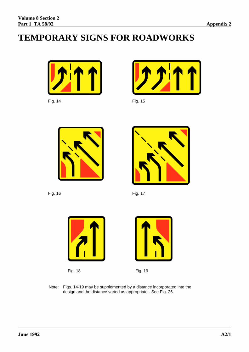
Fig. 14
Note: Figs. 14-19 may be supplemented by a distance incorporated into thedesign and the distance varied as appropriate - See Fig. 26.
Fig. 15
Fig. 16 Fig. 17
Fig. 18 Fig. 19
Volume 8 Section 2Part 1 TA 58/92 Appendix 2
ELECTRONIC COPY - NOT FOR USE OUTSIDE THE AGENCY
June 1992 PAPER COPIES OF THIS ELECTRONIC DOCUMENT ARE UNCONTROLLED A2/1
TEMPORARY SIGNS FOR ROADWORKS

Fig. 20
Note: Figs. 20-25 may be supplementedby a distance incorporated into thedesign and the distance varied asappropriate - See Fig. 26.
Fig. 21
Fig. 22 Fig. 23
Fig. 24 Fig. 25
Fig. 26 Refer to Note
Volume 8 Section 2Apppendix 2 Part 1 TA 58/92
ELECTRONIC COPY - NOT FOR USE OUTSIDE THE AGENCY
PAPER COPIES OF THIS ELECTRONIC DOCUMENT ARE UNCONTROLLED June 1992A2/2

Fig. 27
Note: Figs. 27-30 may be supplemented by a distance incorporated into thedesign and the distance varied as appropriate - See Fig. 26.
Fig. 28
Fig. 29 Fig. 30
Volume 8 Section 2Part 1 TA 58/92 Appendix 2
ELECTRONIC COPY - NOT FOR USE OUTSIDE THE AGENCY
June 1992 PAPER COPIES OF THIS ELECTRONIC DOCUMENT ARE UNCONTROLLED A2/3

Volume 8 Section 2Part 1 TA 58/92 Appendix 3
ELECTRONIC COPY - NOT FOR USE OUTSIDE THE AGENCY
June 1992 PAPER COPIES OF THIS ELECTRONIC DOCUMENT ARE UNCONTROLLED A3/1
TABLES
TABLE 1: REPLACEMENT TEMPORARY SIGNS IN PERMANENT LANE GAIN/DROP LOCATIONS
PERMANENT TEMPORARY SITUATION REMARKSSIGN (Fig. No.) SIGN (Fig. No.)
1 29(++) Additional "gained" lane, or (*) Road markings to Diag 1010
2 14(++) "gained" lane layout, closed at
3 30(*) merge entry point. permanent signs and site
4 18 & 16 (**) signs to Figs 5 or 6, and 3.
5 18(*) markings to sections 2.5 iii - iv.
6 19(*) (++) See below.
7 18 or 19 &30(**) (*)
nearside "gained" lane of a two across merge taper required.
or within 750 metres of the (**) Temporarily cover the
temporary signs as for permanent
Include arrows and ghost
1 ( Additional "gained" lane(s) These cases are considered to be2 ( closed beyond 750 metres from sufficiently outside the influence3 ( No change merge entry point. of the Road Works to be left as4 ( permanent signs. Install5 ( temporary signs on the main6 ( carriageway to Fig 27 plated with
distance (see section 4.7)
11 cover Lane to be dropped is closed to12 sign traffic up to the junction.
1 14(++) Loss of outside (fast) lane and (++) The number of lane arrows2 15(++) any number of adjacent lanes up should be varied to indicate those3 16(++) to and including lane 2. available on the main carriageway.4 17(++)5 18(++)6 19(++)7 20(++)11 24(++)12 25(++)
2 29 Additional two "gained" lanes Markings to Diag 1010 across4 30 closed at or within 750 metres merge taper required.
of the merge entry point.
9 WBM(R) 858.3 "Gained" lane closed. It may be more appropriate to10 WBM(R) 858.3 temporarily blank signs to Figs 9
or 10.

Volume 8 Section 2Apppendix 3 Part 1 TA 58/92
ELECTRONIC COPY - NOT FOR USE OUTSIDE THE AGENCY
PAPER COPIES OF THIS ELECTRONIC DOCUMENT ARE UNCONTROLLED June 1992A3/2
TABLE 2: PERMANENT SIGNS AND THEIR TEMPORARY EQUIVALENT
PERMANENT TEMPORARYSIGN (Fig. No.) SIGN (Fig. No.)
1 14
2 15
3 16
4 17
5 18
6 19
7 20
8 21
9 22
10 23
11 24
12 25
13 26
No equivalent 27
No equivalent 28
No equivalent 29
No equivalent 30

DIAGRAMMATIC ROAD LAYOUTS
3
3
1 1
Dia.1 Single lane slip road to single lane gain at a junction
4
4
4
4
2 2
Dia. 2 Two lane slip road to two lane gain at a junction
5
5
5
5
3
1 1
Dia. 3 Two lane slip road to single lane gain at a junction
6
6 6
63
1 1
Dia. 4 Two lane slip road to single lane gain at a junction (variant 1)
Volume 8 Section 2Part 1 TA 58/92 Appendix 4
ELECTRONIC COPY - NOT FOR USE OUTSIDE THE AGENCY
June 1992 PAPER COPIES OF THIS ELECTRONIC DOCUMENT ARE UNCONTROLLED A4/1
DIAGRAMMATIC ROAD LAYOUTS

7
7
8 8
3
Diagram 1010 Marking
Diagram 1004 Marking
Diagram 1010 Marking
Diagram 1010 Marking
Dia. 5 Two lane slip road to a single lane gain
at a junction (variant 2)
9 9
99
Dia. 6 Single lane gain between junctions
10 10
1010
Dia. 7 Single lane gain betwen junctions (variant)
11 Half-Mile ADS
Dia. 8 Single lane drop at a junction
12 Half-Mile ADS
Dia. 9 Two lane drop at a junction
Volume 8 Section 2Apppendix 4 Part 1 TA 58/92
ELECTRONIC COPY - NOT FOR USE OUTSIDE THE AGENCY
PAPER COPIES OF THIS ELECTRONIC DOCUMENT ARE UNCONTROLLED June 1992A4/2

"Off" Sliproad carriageway
"On" Sliproad carriageway
Main Motorway Carriageway
Main Motorway Carriageway
"THE BACK OF THE MERGE NOSE"
"THE DIVERGE NOSE TIP"
"THE MERGE TIP"
STANDARD MERGE
Dia. 10 Points of reference for siting traffic signs
STANDARD DIVERGE
Volum
e 8 Section 2
Part 1 T
A 58/92
Appendix 4
ELE
CT
RO
NIC
CO
PY
- NO
T F
OR
US
E O
UT
SID
E T
HE
AG
EN
CY
June 1992P
AP
ER
CO
PIE
S O
F T
HIS
ELE
CT
RO
NIC
DO
CU
ME
NT
AR
E U
NC
ON
TR
OLLE
DA
4/3