dnv-rp-j301: subsea power cables in shallow water renewable
TRANSCRIPT
RECOMMENDED PRACTICE
The electronic
DNV-RP-J301
Subsea Power Cables in Shallow Water Renewable Energy Applications
FEBRUARY 2014
DET NORSKE VERITAS AS
pdf version of this document found through http://www.dnv.com is the officially binding version

FOREWORD
DNV is a global provider of knowledge for managing risk. Today, safe and responsible business conduct is both a licenseto operate and a competitive advantage. Our core competence is to identify, assess, and advise on risk management. Fromour leading position in certification, classification, verification, and training, we develop and apply standards and bestpractices. This helps our customers safely and responsibly improve their business performance. DNV is an independentorganisation with dedicated risk professionals in more than 100 countries, with the purpose of safeguarding life, propertyand the environment.
DNV service documents consist of among others the following types of documents:— Service Specifications. Procedural requirements.— Standards. Technical requirements.— Recommended Practices. Guidance.
The Standards and Recommended Practices are offered within the following areas:A) Qualification, Quality and Safety MethodologyB) Materials TechnologyC) StructuresD) SystemsE) Special FacilitiesF) Pipelines and RisersG) Asset OperationH) Marine OperationsJ) Cleaner Energy
O) Subsea SystemsU) Unconventional Oil & Gas
© Det Norske Veritas AS February 2014
Any comments may be sent by e-mail to [email protected]
This service document has been prepared based on available knowledge, technology and/or information at the time of issuance of this document, and is believed to reflect the best ofcontemporary technology. The use of this document by others than DNV is at the user's sole risk. DNV does not accept any liability or responsibility for loss or damages resulting fromany use of this document.
Recommended Practice DNV-RP-J301, February 2014
CHANGES – CURRENT – Page 3
CHANGES – CURRENT
General
Det Norske Veritas AS, company registration number 945 748 931, has on 27th November 2013 changed itsname to DNV GL AS. For further information, see www.dnvgl.com. Any reference in this document to“Det Norske Veritas AS” or “DNV” shall therefore also be a reference to “DNV GL AS”.
This is a new document.
Acknowledgement
This recommended practice was developed by a Joint Industry Project (JIP). The work was performed by DNVand discussed in regular project meetings and workshops with individuals from the participating companies.They are hereby acknowledged for their valuable and constructive input. In case consensus has not beenachievable, DNV has sought to provide acceptable compromise.
Sponsors of the JIP included the following organisations:
Further organisations have participated in the review process. DNV is grateful for the valuable co-operationsand discussions with individuals in these organisations
Bohlen & Doyen Boskalis OffshoreDONG Energy Electrabel GDF SUEZIberdrola S.A. Inch Cape (Repsol, EDPR)JDR Cable Systems Norddeutsche SeekabelwerkeOffshore Marine Management Siem Offshore ContractorsTekmar Energy Tideway Offshore SolutionsVan Oord Offshore Wind Projects B.V. Visser & Smit Marine Contracting
DET NORSKE VERITAS AS
Recommended Practice DNV-RP-J301, February 2014
Contents – Page 4
CONTENTS
CHANGES – CURRENT ................................................................................................................... 3
1 General ....................................................................................................................................... 8
1.1 General............................................................................................................................................................ 8
1.1.1 Introduction ........................................................................................................................................ 81.1.2 Objectives........................................................................................................................................... 81.1.3 Scope and application ........................................................................................................................ 81.1.4 Alternative methods and procedures .................................................................................................. 91.1.5 Structure of the recommended practice.............................................................................................. 9
1.2 References....................................................................................................................................................... 9
1.2.1 Applicability....................................................................................................................................... 91.2.2 Standards - Normative...................................................................................................................... 101.2.3 Standards - Informative.................................................................................................................... 101.2.4 Guidelines - Informative .................................................................................................................. 111.2.5 Other references - Informative ......................................................................................................... 12
1.3 Definitions..................................................................................................................................................... 12
1.3.1 Verbal forms..................................................................................................................................... 121.3.2 Definitions........................................................................................................................................ 12
1.4 Abbreviations and symbols ......................................................................................................................... 23
1.4.1 Abbreviations ................................................................................................................................... 231.4.2 Symbols............................................................................................................................................ 24
2 Design philosophy.................................................................................................................... 26
2.1 General.......................................................................................................................................................... 26
2.1.1 Objective .......................................................................................................................................... 262.1.2 Application....................................................................................................................................... 262.1.3 Stakeholders and interfaces.............................................................................................................. 26
2.2 Safety philosophy ......................................................................................................................................... 27
2.2.1 General ............................................................................................................................................. 272.2.2 Safety objective ................................................................................................................................ 272.2.3 Systematic review of risks ............................................................................................................... 282.2.4 Dependability and risk based design................................................................................................ 292.2.5 Quality assurance ............................................................................................................................. 29
2.3 Design format ............................................................................................................................................... 29
2.3.1 Approach .......................................................................................................................................... 292.3.2 System analysis ................................................................................................................................ 30
3 Concept development .............................................................................................................. 34
3.1 General.......................................................................................................................................................... 34
3.2 Conceptual design ........................................................................................................................................ 34
3.2.1 Systematic approach......................................................................................................................... 343.2.2 Project layout ................................................................................................................................... 343.2.3 Electrical system studies .................................................................................................................. 353.2.4 Preliminary cable selection .............................................................................................................. 363.2.5 Preliminary engineering ................................................................................................................... 37
3.3 Cable route study......................................................................................................................................... 38
3.3.1 General ............................................................................................................................................. 383.3.2 Route selection and landing ............................................................................................................. 383.3.3 Regulatory requirements .................................................................................................................. 393.3.4 Commercial operations, restricted areas, obstructions..................................................................... 393.3.5 Geology and seismicity .................................................................................................................... 413.3.6 Meteorological and marine conditions............................................................................................. 423.3.7 Natural environment......................................................................................................................... 43
3.4 Cable route survey....................................................................................................................................... 45
3.4.1 General ............................................................................................................................................. 453.4.2 Onshore surveys ............................................................................................................................... 463.4.3 Offshore surveys .............................................................................................................................. 463.4.4 Determination of site conditions ...................................................................................................... 49
4 Design ....................................................................................................................................... 51
4.1 General.......................................................................................................................................................... 51
4.2 Cable system design conditions .................................................................................................................. 51
DET NORSKE VERITAS AS
Recommended Practice DNV-RP-J301, February 2014
Contents – Page 5
4.2.1 General ............................................................................................................................................. 514.2.2 Project description............................................................................................................................ 514.2.3 Functional requirements................................................................................................................... 514.2.4 Design basis ..................................................................................................................................... 52
4.3 Cable system design ..................................................................................................................................... 52
4.3.1 Detailed design................................................................................................................................. 524.3.2 Installation engineering.................................................................................................................... 52
4.4 Cable system................................................................................................................................................. 53
4.4.1 Power cables..................................................................................................................................... 534.4.2 Power cable accessories ................................................................................................................... 574.4.3 Optical fibres .................................................................................................................................... 57
4.5 Cable route ................................................................................................................................................... 58
4.5.1 General ............................................................................................................................................. 584.5.2 Parallel routing of power cables....................................................................................................... 594.5.3 Proximity to existing infrastructure ................................................................................................. 604.5.4 Crossing of existing infrastructure ................................................................................................... 60
4.6 Cable protection........................................................................................................................................... 61
4.6.1 General ............................................................................................................................................. 614.6.2 Additional armour ............................................................................................................................ 624.6.3 Cable burial ...................................................................................................................................... 624.6.4 Non-burial cable protection.............................................................................................................. 65
4.7 Cable interface at fixed offshore units ....................................................................................................... 67
4.7.1 General ............................................................................................................................................. 674.7.2 Offshore unit .................................................................................................................................... 674.7.3 Interface between cable and offshore unit ....................................................................................... 714.7.4 Interface components ....................................................................................................................... 744.7.5 Scour and scour protection............................................................................................................... 78
4.8 Landfall......................................................................................................................................................... 79
4.8.1 General ............................................................................................................................................. 794.8.2 Open-cut trench................................................................................................................................ 814.8.3 Horizontal directional drilling.......................................................................................................... 814.8.4 Onshore jointing location................................................................................................................. 83
5 Manufacturing ......................................................................................................................... 84
5.1 General.......................................................................................................................................................... 84
5.1.1 Quality system and workmanship .................................................................................................... 845.1.2 Inspection ......................................................................................................................................... 84
5.2 Cable manufacturing and testing ............................................................................................................... 84
5.2.1 General ............................................................................................................................................. 845.2.2 Power cable type tests ...................................................................................................................... 855.2.3 Power cable sample tests.................................................................................................................. 865.2.4 Power cable routine tests.................................................................................................................. 865.2.5 Optical fibre manufacturing and testing........................................................................................... 86
5.3 Cable storage, load-out and transport ....................................................................................................... 86
5.3.1 Cable storage.................................................................................................................................... 865.3.2 Cable load-out .................................................................................................................................. 875.3.3 Cable transport ................................................................................................................................. 89
5.4 Cable accessories.......................................................................................................................................... 89
5.5 Cable protection measures.......................................................................................................................... 89
5.6 Offshore units............................................................................................................................................... 90
5.7 Spare parts.................................................................................................................................................... 90
6 Installation ............................................................................................................................... 91
6.1 General.......................................................................................................................................................... 91
6.1.1 General ............................................................................................................................................. 916.1.2 Planning of operations...................................................................................................................... 916.1.3 Operational limiting conditions........................................................................................................ 916.1.4 Diver intervention ............................................................................................................................ 92
6.2 Installation spread ....................................................................................................................................... 93
6.2.1 General ............................................................................................................................................. 936.2.2 Cable installation vessels ................................................................................................................. 936.2.3 Support vessels................................................................................................................................. 946.2.4 Positioning systems.......................................................................................................................... 946.2.5 Cable handling equipment................................................................................................................ 976.2.6 Mobilisation ..................................................................................................................................... 99
DET NORSKE VERITAS AS
Recommended Practice DNV-RP-J301, February 2014
Contents – Page 6
6.2.7 Cable burial equipment .................................................................................................................... 99
6.3 Pre-lay survey and route preparation...................................................................................................... 105
6.3.1 Pre-installation route survey .......................................................................................................... 1056.3.2 Cable route preparation .................................................................................................................. 105
6.4 Cable laying................................................................................................................................................ 106
6.4.1 Cable installation............................................................................................................................ 1066.4.2 Weather vaning, abandonment and recovery ................................................................................. 1076.4.3 Jointing........................................................................................................................................... 108
6.5 Cable pull into offshore unit ..................................................................................................................... 109
6.5.1 General ........................................................................................................................................... 1096.5.2 Preparations.................................................................................................................................... 1096.5.3 Cable first-end pull......................................................................................................................... 1106.5.4 Cable second-end pull .................................................................................................................... 1116.5.5 Cable fixing.................................................................................................................................... 112
6.6 Landfall....................................................................................................................................................... 112
6.6.1 General ........................................................................................................................................... 1126.6.2 Open-cut trenching......................................................................................................................... 1136.6.3 Horizontal directional drilling........................................................................................................ 1136.6.4 Cable pull-in................................................................................................................................... 1156.6.5 Interface with land-based system ................................................................................................... 116
6.7 Cable protection......................................................................................................................................... 116
6.7.1 General ........................................................................................................................................... 1166.7.2 Cable burial .................................................................................................................................... 1166.7.3 Non-burial protection ..................................................................................................................... 1176.7.4 Infrastructure crossings .................................................................................................................. 118
6.8 As-built survey ........................................................................................................................................... 118
6.8.1 General ........................................................................................................................................... 1186.8.2 Survey requirements....................................................................................................................... 118
6.9 Commissioning and testing ....................................................................................................................... 119
6.9.1 Termination .................................................................................................................................... 1196.9.2 Testing............................................................................................................................................ 119
7 Operation and maintenance ................................................................................................. 121
7.1 General........................................................................................................................................................ 121
7.2 Asset management ..................................................................................................................................... 121
7.2.1 Asset management system ............................................................................................................. 1217.2.2 Asset management process ............................................................................................................ 122
7.3 Monitoring, testing and inspection........................................................................................................... 122
7.3.1 Monitoring and testing ................................................................................................................... 1227.3.2 Inspection ....................................................................................................................................... 1237.3.3 Security surveillance ...................................................................................................................... 124
7.4 Remedial work ........................................................................................................................................... 125
7.4.1 Minimum cable protection ............................................................................................................. 1257.4.2 Free span rectification .................................................................................................................... 125
7.5 Fault detection and location...................................................................................................................... 125
7.5.1 General ........................................................................................................................................... 1257.5.2 Cable location................................................................................................................................. 1257.5.3 Fault location.................................................................................................................................. 125
7.6 Repair work................................................................................................................................................ 126
7.6.1 General ........................................................................................................................................... 1267.6.2 Repair planning .............................................................................................................................. 1277.6.3 Repair execution............................................................................................................................. 127
7.7 Requalification ........................................................................................................................................... 128
7.7.1 General ........................................................................................................................................... 1287.7.2 Change of design criteria ............................................................................................................... 1287.7.3 System test ..................................................................................................................................... 128
8 Decommissioning ................................................................................................................... 129
8.1 General........................................................................................................................................................ 129
8.2 Withdrawal from service........................................................................................................................... 129
8.3 Removal ...................................................................................................................................................... 129
DET NORSKE VERITAS AS
Recommended Practice DNV-RP-J301, February 2014
Contents – Page 7
9 Documentation....................................................................................................................... 131
9.1 General........................................................................................................................................................ 131
9.2 Documents .................................................................................................................................................. 131
9.2.1 Concept development..................................................................................................................... 1319.2.2 Design basis ................................................................................................................................... 1329.2.3 Design ............................................................................................................................................ 1339.2.4 Manufacturing ................................................................................................................................ 1339.2.5 Installation...................................................................................................................................... 1349.2.6 Operation and maintenance............................................................................................................ 1369.2.7 Decommissioning........................................................................................................................... 136
App. A Hazard identification ................................................................................................... 137
A.1 General .......................................................................................................................................... 137A.2 Health and safety risks .................................................................................................................. 137A.3 Environmental risks ...................................................................................................................... 138A.4 Project risks ................................................................................................................................... 139
App. B Subsea power cable specifications .............................................................................. 142
B.1 General .......................................................................................................................................... 142B.2 Project information........................................................................................................................ 142B.3 Electrical specifications ................................................................................................................ 142B.4 Thermal specifications .................................................................................................................. 143B.5 Mechanical specifications ............................................................................................................. 144B.6 Cable component features ............................................................................................................. 144
DET NORSKE VERITAS AS
Recommended Practice DNV-RP-J301, February 2014
Sec.1 General – Page 8
1 General
1.1 General
1.1.1 Introduction
This recommended practice provides guidance for all phases of the life cycle of subsea power cable projects,with a focus on static service in shallow water renewable energy applications.
1.1.2 Objectives
The objectives of this recommended practice are to:
— ensure that the various phases of subsea power cable systems, i.e. concept development, design,manufacturing, testing, storage, load-out, transport, installation, commissioning, operation, maintenanceand decommissioning, are conducted with due regard for health and safety, the protection of theenvironment and quality
— promote a risk based approach whereby risks are reduced to acceptable levels— provide internationally applicable guidance by defining minimum requirements which constitute industry
‘best practice’— serve as a reference document between stakeholders such as developers, designers, manufacturers,
purchasers, installers, owners, operators, certifiers, investors and insurers.
Guidance note:
Locally applicable regulations should be consulted to ensure that all requirements, which can be in excess of theguidance provided in this recommended practice, are being met.
---e-n-d---of---G-u-i-d-a-n-c-e---n-o-t-e---
1.1.3 Scope and application
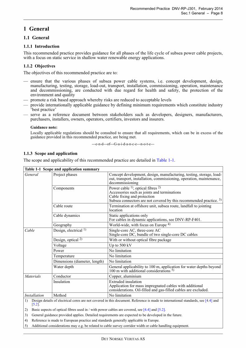
The scope and applicability of this recommended practice are detailed in Table 1-1.
Table 1-1 Scope and application summary
General Project phases Concept development, design, manufacturing, testing, storage, load-out, transport, installation, commissioning, operation, maintenance, decommissioning
Components Power cable 1), optical fibres 2)
Accessories such as joints and terminationsCable fixing and protectionSubsea connectors are not covered by this recommended practice. 3)
Cable route Termination at offshore unit, subsea route, landfall to jointing location
Cable dynamics Static applications onlyFor cables in dynamic applications, see DNV-RP-F401.
Geography World-wide, with focus on Europe 4)
Cable Design, electrical 1) Single-core AC, three-core ACSingle-core DC, bundle of two single-core DC cables
Design, optical 2) With or without optical fibre packageVoltage Up to 500 kVPower No limitationTemperature No limitationDimensions (diameter, length) No limitationWater depth General applicability to 100 m, application for water depths beyond
100 m with additional considerations 5)
Materials Conductor Copper, aluminiumInsulation Extruded insulation
Application for mass impregnated cables with additional considerations. Oil-filled and gas-filled cables are excluded.
Installation Method No limitation1) Design details of electrical cores are not covered in this document. Reference is made to international standards, see [4.4] and
[5.2].
2) Basic aspects of optical fibres used in / with power cables are covered, see [4.4] and [5.2].
3) General guidance provided applies. Detailed requirements are expected to be developed in the future.
4) Reference is made to European practice and standards generally applicable in Europe.
5) Additional considerations may e.g. be related to cable survey corridor width or cable handling equipment.
DET NORSKE VERITAS AS
Recommended Practice DNV-RP-J301, February 2014
Sec.1 General – Page 9
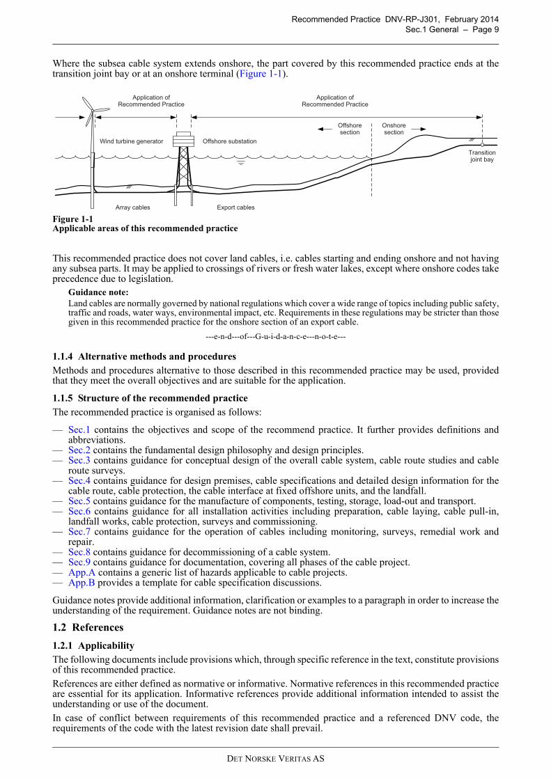
Where the subsea cable system extends onshore, the part covered by this recommended practice ends at thetransition joint bay or at an onshore terminal (Figure 1-1).
Figure 1-1Applicable areas of this recommended practice
This recommended practice does not cover land cables, i.e. cables starting and ending onshore and not havingany subsea parts. It may be applied to crossings of rivers or fresh water lakes, except where onshore codes takeprecedence due to legislation.
Guidance note:
Land cables are normally governed by national regulations which cover a wide range of topics including public safety,traffic and roads, water ways, environmental impact, etc. Requirements in these regulations may be stricter than thosegiven in this recommended practice for the onshore section of an export cable.
---e-n-d---of---G-u-i-d-a-n-c-e---n-o-t-e---
1.1.4 Alternative methods and procedures
Methods and procedures alternative to those described in this recommended practice may be used, providedthat they meet the overall objectives and are suitable for the application.
1.1.5 Structure of the recommended practice
The recommended practice is organised as follows:
— Sec.1 contains the objectives and scope of the recommend practice. It further provides definitions andabbreviations.
— Sec.2 contains the fundamental design philosophy and design principles.— Sec.3 contains guidance for conceptual design of the overall cable system, cable route studies and cable
route surveys.— Sec.4 contains guidance for design premises, cable specifications and detailed design information for the
cable route, cable protection, the cable interface at fixed offshore units, and the landfall.— Sec.5 contains guidance for the manufacture of components, testing, storage, load-out and transport.— Sec.6 contains guidance for all installation activities including preparation, cable laying, cable pull-in,
landfall works, cable protection, surveys and commissioning.— Sec.7 contains guidance for the operation of cables including monitoring, surveys, remedial work and
repair.— Sec.8 contains guidance for decommissioning of a cable system.— Sec.9 contains guidance for documentation, covering all phases of the cable project.— App.A contains a generic list of hazards applicable to cable projects.— App.B provides a template for cable specification discussions.
Guidance notes provide additional information, clarification or examples to a paragraph in order to increase theunderstanding of the requirement. Guidance notes are not binding.
1.2 References
1.2.1 Applicability
The following documents include provisions which, through specific reference in the text, constitute provisionsof this recommended practice.
References are either defined as normative or informative. Normative references in this recommended practiceare essential for its application. Informative references provide additional information intended to assist theunderstanding or use of the document.
In case of conflict between requirements of this recommended practice and a referenced DNV code, therequirements of the code with the latest revision date shall prevail.
Application ofRecommended Practice
Application ofRecommended Practice
Transitionjoint bay
Onshore section
Offshore section
Array cables Export cables
Offshore substationWind turbine generator
DET NORSKE VERITAS AS
Recommended Practice DNV-RP-J301, February 2014
Sec.1 General – Page 10
Guidance note:
DNV code means any DNV Offshore Service Specification, DNV Offshore Standard, DNV Recommended Practice,DNV Guideline or DNV Classification Note.
Any conflict is intended to be removed in the next revision of the document concerned.
---e-n-d---of---G-u-i-d-a-n-c-e---n-o-t-e---
Where reference is made to documents other than DNV codes, the valid revision should be taken as the revisionwhich was current at the date of issue of this recommended practice.
1.2.2 Standards - Normative
1.2.3 Standards - Informative
IEC 60183 Guide to the selection of high-voltage cables
IEC 60502 Power cables with extruded insulation and their accessories for rated voltages from 1 kV (Um = 1,2 kV) up to 30 kV (Um = 36 kV)
IEC 60840 Power cables with extruded insulation and their accessories for rated voltages above 30 kV (Um = 36 kV) up to 150 kV (Um = 170 kV) - Test methods and requirements
IEC 62067 Power cables with extruded insulation and their accessories for rated voltages above 150 kV (Um = 170 kV) up to 500 kV (Um = 550 kV) - Test methods and requirements
DNV-OS-E301 Position mooring
DNV-OS-F101 Submarine pipeline systems
DNV-OS-H101 Marine operations, general
DNV-OS-H203 Transit and positioning of mobile offshore units
EN 13383-1 Armourstone - Part 1: Specification
IEC 60071-1 Insulation co-ordination - Part 1: Definitions, principles and rules
IEC 60228 Conductors of insulated cables
IEC 60287-1-1 Electric cables - Calculation of the current rating - Part 1-1: Current rating equations (100% load factor) and calculation of losses - General
IEC 60287-2-1 Electric cables - Calculation of the current rating - Part 2-1: Thermal resistance - Calculation of thermal resistance
IEC 60287-3-2 Electric cables - Calculation of the current rating - Part 3-2: Sections on operating conditions - Economic optimization of power cable size
IEC 60300-1 Dependability management - Part 1: Dependability management systems
IEC 60793 Optical fibres
IEC 60794 Optical fibre cables
IEC 60853-1 Calculation of the cyclic and emergency current rating of cables - Part 1: Cyclic rating factor for cables up to and including 18/30 (36) kV
IEC 60853-2 Calculation of the cyclic and emergency current rating of cables - Part 2: Cyclic rating of cables greater than 18/30 (36) kV and emergency ratings for cables of all voltages
IEC 60949 Calculation of thermally permissible short-circuit currents, taking into account non-adiabatic heating effects
IEC 61400-3 Wind turbines - Part 3: Design requirements for offshore wind turbines
IEC 61443 Short-circuit temperature limits of electric cables with rated voltages above 30 kV (Um = 36 kV)
ISO 9001 Quality management systems - Requirements
ISO 13623 Petroleum and natural gas industries - Pipeline transportation systems
ISO 13628-2 Petroleum and natural gas industries - Design and operation of subsea production systems - Part 2: Unbonded flexible pipe systems for subsea and marine applications
ISO 13628-5 Petroleum and natural gas industries - Design and operation of subsea production systems - Part 5: Subsea umbilicals
ISO 14688-1 Geotechnical investigation and testing - Identification and classification of soil - Part 1: Identification and description
ISO 14688-2 Geotechnical investigation and testing - Identification and classification of soil - Part 2: Principles for a classification
DET NORSKE VERITAS AS
Recommended Practice DNV-RP-J301, February 2014
Sec.1 General – Page 11
1.2.4 Guidelines - Informative
ISO 19901-6 Petroleum and natural gas industries - Specific requirements for offshore structures - Part 6: Marine operations
ISO 22475-1 Geotechnical investigation and testing - Sampling methods and groundwater measurements - Part 1: Technical principles for execution
ISO 31000 Risk management - Principles and guidelines
ISO 31010 Risk management - Risk assessment techniques
ISO 55000 Asset management - Overview, principles and terminology
ITU-T G.976 Test methods applicable to optical fibre submarine cable systems
NORSOK G-001 Marine soil investigations
NORSOK N-004 Design of steel structures
BSH 7004 Baugrunderkundung für Offshore-Energieparks (Ground investigation for offshore wind farms)
BSH 7005 Konstruktive Ausführung von Offshore-Windenergieanlagen (Design of offshore wind turbines)
CIGRÉ Technical Brochure 177
Accessories for HV cables with extruded insulation
CIGRÉ Technical Brochure 194
Construction, laying and installation techniques for extruded and self contained fluid filled cable systems
CIGRÉ Technical Brochure 303
Revision of qualification procedures for HV and EHV AC extruded underground cable systems
CIGRÉ Technical Brochure 379
Update of service experience of HV underground and submarine cable systems
CIGRÉ Technical Brochure 398
Third-party damage to underground and submarine cables
CIGRÉ Technical Brochure 415
Test procedures for HV transition joints for rated voltages 30 kV (Um = 36 kV) up to 500 kV (Um = 550 kV)
CIGRÉ Technical Brochure 476
Cable accessory workmanship on extruded high voltage cables
CIGRÉ Technical Brochure 483
Guidelines for the design and construction of AC offshore substations for wind power plants
CIGRÉ Technical Brochure 490
Recommendations for testing of long AC submarine cables with extruded insulation for system voltage above 30 (36) to 500 (550) kV
CIGRÉ Technical Brochure 496
Recommendations for testing DC extruded cable systems for power transmission at a rated voltage up to 500 kV
CIGRÉ Technical Brochure 560
Guideline to maintaining the integrity of XLPE cable accessories
CIGRÉ Electra 171 Recommendations for mechanical tests on sub-marine cables
CIGRÉ Electra 189 Recommendations for tests of power transmission DC cables for a rated voltage up to 800 kV
CIRIA Guideline C683 The rock manual - The use of rock in hydraulic engineering
CIRIA Guideline C685 Beach management manual
DNV-RP-C205 Environmental conditions and environmental loads
DNV-RP-C207 Statistical representation of soil data
DNV-RP-F105 Free spanning pipelines
DNV-RP-F107 Risk assessment of pipeline protection
DNV-RP-F401 Electrical power cables in subsea applications
DNV-RP-H101 Risk management in marine and subsea operations
DNV-RP-H102 Marine operations during removal of offshore installations
ICPC Recommendation 1 Recovery of out-of-service cables
ICPC Recommendation 2 Cable Routing and Reporting Criteria
ICPC Recommendation 3 Telecommunications Cable and Oil Pipeline / Power Cables Crossing Criteria
ICPC Recommendation 6 Recommended actions for effective cable protection (post installation)
DET NORSKE VERITAS AS
Recommended Practice DNV-RP-J301, February 2014
Sec.1 General – Page 12
1.2.5 Other references - Informative
Allan, P.G. (1998). Selecting appropriate cable burial depths - A methodology, IBC Conference on SubmarineCommunications. The future of network infrastructure, Cannes, November 1998.
Offshore Site Investigation and Geotechnics Committee (OSIG) (2014). Guidance notes for the planning andexecution of geophysical and geotechnical ground investigations for offshore renewable energy developments.
Red Penguin (Red Penguin Associates) (2012). Export transmission cables for offshore renewable installations- Principles for cable routeing and spacing, rev. 1, The Crown Estate, August 2012.
Sumer, B.M. and Fredsøe, J. (2002). The mechanics of scour in the marine environment. Advanced series onocean engineering - Volume 17. World Scientific.
Worzyk, T. (2009). Submarine power cables. Design, installation, repair, environmental aspects, Springer,Berlin, Heidelberg.
1.3 Definitions
1.3.1 Verbal forms
1.3.2 Definitions
ICPC Recommendation 9 Minimum technical requirements for a desktop study (also known as cable route study)
ICPC Recommendation 11 Standardization of electronic formatting of route position lists
ICPC Recommendation 13 Proximity of wind farm developments & submarine cables
IHO S-44 Standards for hydrographic surveys
IMCA D 014 International code of practice for offshore diving
IMCA D 042 (R 016) Diver and ROV based concrete mattress handling, deployment, installation, repositioning and decommissioning
IMCA M 125 Safety interface documents for a DP vessel working near an offshore platform
IMCA M 140 Specification of DP capacity plots
IMCA M 190 Developing and conducting annual DP trials programmes for DP vessels
IMO MSC/Circ.645 Guidelines for vessels with dynamic positioning systems
IMO Res. A.1047 (27) Principles of minimum safe manning
Subsea Cables UK Guideline 6
The proximity of offshore renewable energy installations & submarine cable infrastructure in UK waters
Subsea Cables UK Guideline 8
Submarine cable decommissioning
Shall Verbal form used to indicate requirements strictly to be followed in order to conform to the document.
Should Verbal form used to indicate that among several possibilities one is recommended as particularly suitable, without mentioning or excluding others, or that a certain course of action is preferred but not necessarily required.
May Verbal form used to indicate a course of action permissible within the limits of the document.
Agreement, or by Agreement
Unless otherwise indicated, agreed in writing between contracting parties.
Abandonment Activities associated with interrupting installation of a cable and releasing it from the cable installation vessel. Later, installation activities continue with recovery of the cable.
Alter course (A/C) Point on the cable route where the cable course changes bearing.Armour (cable) One or more cable covering(s) made of typically metal tape(s) or wire(s) providing
tensile strength and protecting the cable from external mechanical forces, see [4.4.1.6]. Also referred to as ‘strength member(s)’.
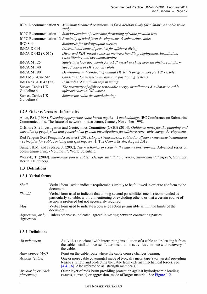
Armour layer (rock placement)
Outer layer of rock berm providing protection against hydrodynamic loading (waves, currents) or aggression, made of larger material. See Figure 1-2.
DET NORSKE VERITAS AS
Recommended Practice DNV-RP-J301, February 2014
Sec.1 General – Page 13
Figure 1-2Rock structure protecting a subsea power cable on the seabed
Armour unit Large quarried stone or specially shaped concrete block used in protective armour layers.
Array cable Subsea power cable connecting an offshore electricity generator with other offshore generators or an offshore substation within a project (e.g. an offshore wind farm).
As-built survey Survey of the installed cable system which is performed to verify the completed installation work.
Beaching Deliberate and controlled grounding of a vessel in a safe working area for cable installation purposes. Used in very shallow water with sufficient tidal range to re-float.
Bedform Depositional feature of the seabed, formed by the movement of sediments due to tidal or wave action. Frequently distinguished into:
— ripples - small-scale bedforms with asymmetrical linguoid forms (produced by tidal currents) or straight crested symmetrical or asymmetrical forms (produced by waves)
— megaripples - intermediate-scale bedforms, formed by waves— sand waves - large-scale bedforms, divisible into rippled and megarippled
ridges, formed by (tidal) currents.
Guidance note 1:
Typically, ripples have heights of less than 0.1 m and wavelengths of less than 0.6 m;megaripples have heights of up to 1 m and wavelengths of up to 30 m; sand waves have heightsexceeding 1 m and wavelengths from 30 m to 500 m.
---e-n-d---of---G-u-i-d-a-n-c-e---n-o-t-e---
Bellmouth Bell shaped opening which provides guidance for a cable, e.g. used at seabed end of J- or I-tubes. See [4.7.4.1] and [4.7.4.2].
Bend restrictor Device for limiting the bend radius of a cable to a specific value by mechanical means. Included in the wider group of ‘bend limiters’. See [4.7.4.5].
Bend stiffener Device which locally increases bending stiffness, reducing bending curvature and stresses of the cable. Also referred to as ‘bend strain reliever’. See [4.7.4.4].
Benthos Collection of flora and fauna living on the sea floor or in the top sediments of the seabed.
Berm A (a) horizontal step or plateau in an embankment or breakwater or (b) nearly horizontal area / small mound at an offshore structure supporting or keying-in an armour layer. Definition may also include the side slope(s), see Figure 1-2.
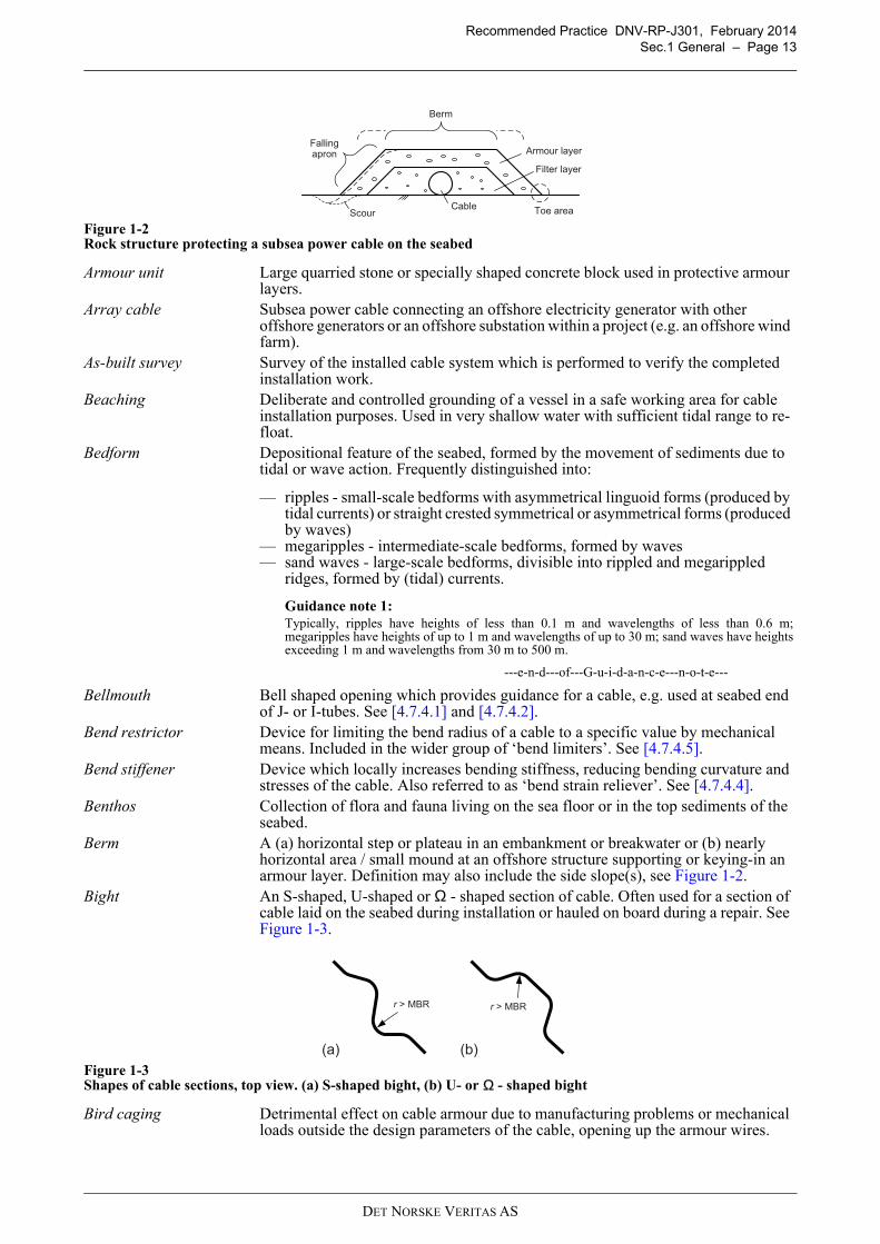
Bight An S-shaped, U-shaped or Ω - shaped section of cable. Often used for a section of cable laid on the seabed during installation or hauled on board during a repair. See Figure 1-3.
Figure 1-3Shapes of cable sections, top view. (a) S-shaped bight, (b) U- or Ω - shaped bight
Bird caging Detrimental effect on cable armour due to manufacturing problems or mechanical loads outside the design parameters of the cable, opening up the armour wires.
Filter layer
Armour layer
Berm
Toe areaCable
Fallingapron
Scour
1.3
(a) (b)
r > MBR r > MBR
DET NORSKE VERITAS AS
Recommended Practice DNV-RP-J301, February 2014
Sec.1 General – Page 14
Bollard pull Continuous static towing force applied by a vessel, e.g. continuous tow line force. A measure of a vessel’s ability to tow.
Bundle A collection of cables fastened together, e.g. two or more AC, DC or fibre optic cables.
Burial Lowering of a cable into the ground (e.g. seabed) and providing a protective cover of soil. See also Figure 1-6.
Burial assessment study Cable protection study, based on hazards to the cable (fishing, shipping, dropped objects) and site conditions (soil properties, sediment mobility), to determine burial depth and suitable tools for a section of cable which meet the risk acceptance criteria.
Guidance note 2:
A ‘tool capability assessment’ can determine the likely performance includingachievable burial depth.
---e-n-d---of---G-u-i-d-a-n-c-e---n-o-t-e---
Burial protection index (BPI)
Qualitative level of protection of a buried cable, relating burial depth to the strength of the seabed, considering potential external aggression, see Allan (1998).
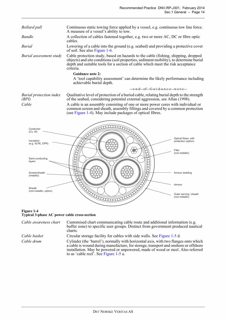
Cable A cable is an assembly consisting of one or more power cores with individual or common screen and sheath, assembly fillings and covered by a common protection (see Figure 1-4). May include packages of optical fibres.
Figure 1-4Typical 3-phase AC power cable cross-section
Cable awareness chart Customised chart communicating cable route and additional information (e.g. buffer zone) to specific user groups. Distinct from government produced nautical charts.
Cable basket Circular storage facility for cables with side walls. See Figure 1-5 d.Cable drum Cylinder (the ‘barrel’), normally with horizontal axis, with two flanges onto which
a cable is wound during manufacture, for storage, transport and onshore or offshore installation. May be powered or unpowered, made of wood or steel. Also referred to as ‘cable reel’. See Figure 1-5 a.
Conductor(Cu, Al)
Optical fibres, with protection (option)
Armour
Outer serving / sheath(non-metallic)
Insulation(e.g. XLPE, EPR)
Filler(non-metallic)
Sheath(non-metallic, option)
Semi-conductinglayers
Screen/sheath(metallic)
Armour bedding
DET NORSKE VERITAS AS
Recommended Practice DNV-RP-J301, February 2014
Sec.1 General – Page 15
1.5
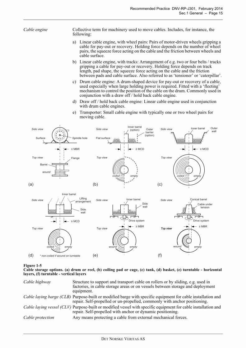
Cable engine Collective term for machinery used to move cables. Includes, for instance, the following:
a) Linear cable engine, with wheel pairs: Pairs of motor-driven wheels gripping a cable for pay-out or recovery. Holding force depends on the number of wheel pairs, the squeeze force acting on the cable and the friction between wheels and cable surface.
b) Linear cable engine, with tracks: Arrangement of e.g. two or four belts / tracks gripping a cable for pay-out or recovery. Holding force depends on track length, pad shape, the squeeze force acting on the cable and the friction between pads and cable surface. Also referred to as ‘tensioner’ or ‘caterpillar’.
c) Drum cable engine: A drum-shaped device for pay-out or recovery of a cable, used especially when large holding power is required. Fitted with a ‘fleeting’ mechanism to control the position of the cable on the drum. Commonly used in conjunction with a draw off / hold back cable engine.
d) Draw off / hold back cable engine: Linear cable engine used in conjunction with drum cable engines.
e) Transporter: Small cable engine with typically one or two wheel pairs for moving cable.
Figure 1-5Cable storage options. (a) drum or reel, (b) coiling pad or cage, (c) tank, (d) basket, (e) turntable - horizontallayers, (f) turntable - vertical layers
Cable highway Structure to support and transport cable on rollers or by sliding, e.g. used in factories, in cable storage areas or on vessels between storage and deployment equipment.
Cable laying barge (CLB) Purpose-built or modified barge with specific equipment for cable installation and repair. Self-propelled or un-propelled, commonly with anchor positioning.
Cable laying vessel (CLV) Purpose-built or modified vessel with specific equipment for cable installation and repair. Self-propelled with anchor or dynamic positioning.
Cable protection Any means protecting a cable from external mechanical forces.
(a) (c)
Inner barrel Outerwall
Side view
Top view
MCD
(b)
Inner barrel(option) Outer
barrier(option)
Side view
Top view
MCD
(d)
Inner barrel
Sidewall
Side view
Top view
MCD
Liftingarrangement
(e)
Inner barrel
Sidewall
Side view
Top view MBR
Drive system
Flat surface
emptycoiled *
emptycoiled emptycoiled
Side view
Top view
Surface
Barrel
Flange
Spindle hole
MBR
wound
Drive system
wound empty
Side view
Top view
Conical barrel
Top view MBR
* non-coiled if wound on turntable (f)
wound empty
Cable undertension
DET NORSKE VERITAS AS
Recommended Practice DNV-RP-J301, February 2014
Sec.1 General – Page 16
Cable protection system Collective term for protective tubular elements which can be fitted onto a cable for mechanical protection to ensure that the cable can operate for its service life.
Cable reel see ‘cable drum’Cable route Path of a cable, onshore and offshore, planned or installed.Cable route study Process of reviewing available information and identifying a safe, technically and
economically viable cable route.Guidance note 3:
In this recommended practice, no distinction is made between a ‘cable routestudy’ and a ‘desktop study’.
---e-n-d---of---G-u-i-d-a-n-c-e---n-o-t-e---
Cable system A subsea power cable system may consist of cable(s), termination(s) and joint(s).Guidance note 4:
Above definition applies specifically for testing of power cables. In a widerdefinition the cable system may also include components like hang-off, cableprotection measures and optical fibres.
---e-n-d---of---G-u-i-d-a-n-c-e---n-o-t-e---
Cable tank A static, circular storage area (on vessel, on land), where cable is coiled. See Figure 1-5 c.
Cable tension Axial force on a cable. Inter-dependent with cable bending.Carousel see ‘turntable’Catenary A curve assumed by a cable suspended between two points (e.g. vessel and seabed).Characteristic value A nominal value characterising the magnitude of a stochastic variable, normally
defined as a fractile of its probability distribution.Chart datum Water level to which water depths and tidal variations are referred to on charts.
Frequently the lowest astronomical tide (LAT).Chute A curved channel for passing a cable from a higher to a lower level, e.g. overboard
a vessel, which does not compromise the mechanical parameters of the cable.Coastal defence Collective term for protection of the coast against erosion (coastal protection) and
flooding (sea defence).Coiling Simultaneous twisting and bending of a cable, one full twist per turn.
Guidance note 5:
If the design of the cable allows and the manufacturer confirms that a cable canbe coiled, it is often referred to as “coilable”. Otherwise, it is referred to as“non-coilable”.
---e-n-d---of---G-u-i-d-a-n-c-e---n-o-t-e---
Coiling pad A flat surface, round or oval, at a cable manufacturing or storage site or in the tank of a cable installation vessel, onto which cables are coiled.
Conductor Part of a cable core designed for transmission of electric current, typically made of copper or aluminium.
Core An assembly consisting of a conductor and its own electrical insulation.Corridor Width of the area along a cable route, specified e.g. for cable route consenting,
surveying purposes or post-construction exclusion zones.Crushing load A mechanical load that acts in the radial direction of the cable, which is limited in
length along the cable.Dependability Collective, non-quantitative term describing availability performance which is
determined by reliability performance, maintainability performance and maintenance support performance, see IEC 60300-1.
DET NORSKE VERITAS AS
Recommended Practice DNV-RP-J301, February 2014
Sec.1 General – Page 17
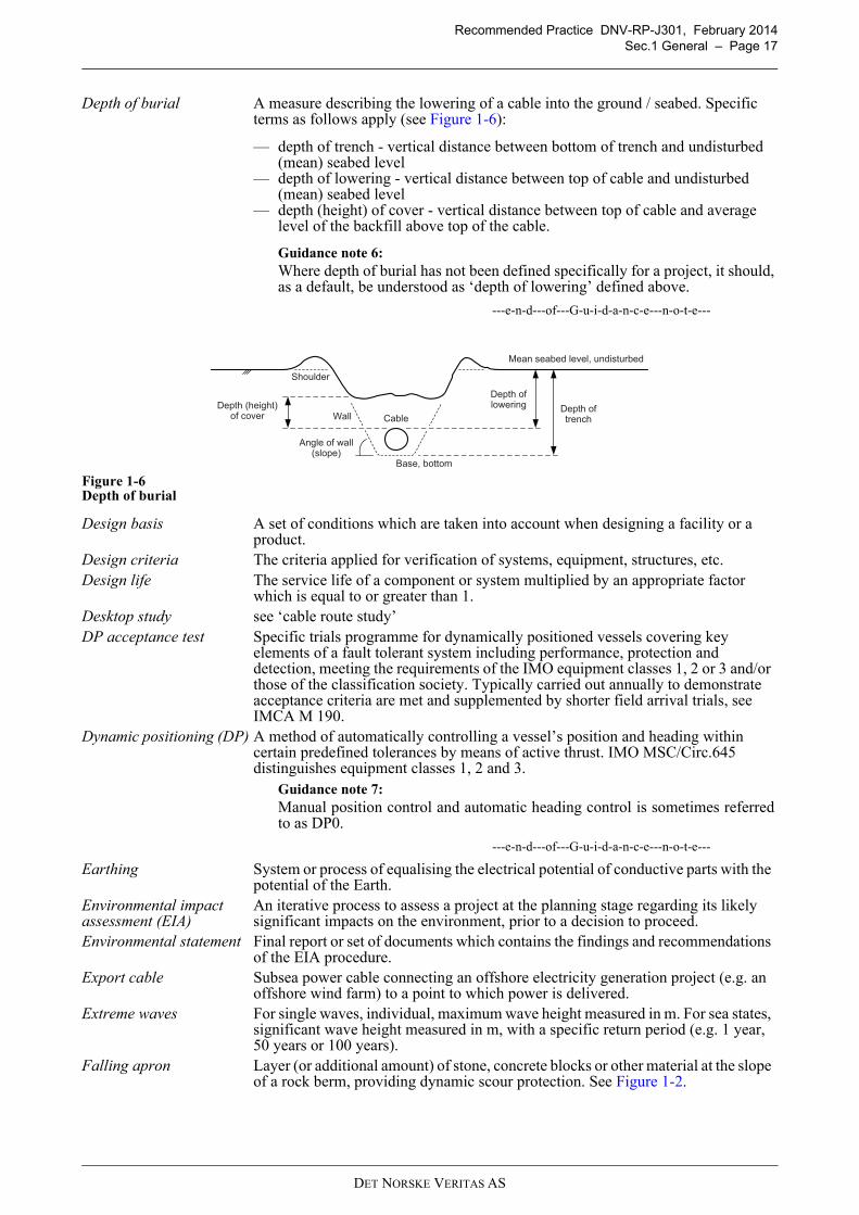
Depth of burial A measure describing the lowering of a cable into the ground / seabed. Specific terms as follows apply (see Figure 1-6):
— depth of trench - vertical distance between bottom of trench and undisturbed (mean) seabed level
— depth of lowering - vertical distance between top of cable and undisturbed (mean) seabed level
— depth (height) of cover - vertical distance between top of cable and average level of the backfill above top of the cable.
Guidance note 6:
Where depth of burial has not been defined specifically for a project, it should,as a default, be understood as ‘depth of lowering’ defined above.
---e-n-d---of---G-u-i-d-a-n-c-e---n-o-t-e---
Figure 1-6Depth of burial
Design basis A set of conditions which are taken into account when designing a facility or a product.
Design criteria The criteria applied for verification of systems, equipment, structures, etc.Design life The service life of a component or system multiplied by an appropriate factor
which is equal to or greater than 1.Desktop study see ‘cable route study’DP acceptance test Specific trials programme for dynamically positioned vessels covering key
elements of a fault tolerant system including performance, protection and detection, meeting the requirements of the IMO equipment classes 1, 2 or 3 and/or those of the classification society. Typically carried out annually to demonstrate acceptance criteria are met and supplemented by shorter field arrival trials, see IMCA M 190.
Dynamic positioning (DP) A method of automatically controlling a vessel’s position and heading within certain predefined tolerances by means of active thrust. IMO MSC/Circ.645 distinguishes equipment classes 1, 2 and 3.
Guidance note 7:
Manual position control and automatic heading control is sometimes referredto as DP0.
---e-n-d---of---G-u-i-d-a-n-c-e---n-o-t-e---
Earthing System or process of equalising the electrical potential of conductive parts with the potential of the Earth.
Environmental impact assessment (EIA)
An iterative process to assess a project at the planning stage regarding its likely significant impacts on the environment, prior to a decision to proceed.
Environmental statement Final report or set of documents which contains the findings and recommendations of the EIA procedure.
Export cable Subsea power cable connecting an offshore electricity generation project (e.g. an offshore wind farm) to a point to which power is delivered.
Extreme waves For single waves, individual, maximum wave height measured in m. For sea states, significant wave height measured in m, with a specific return period (e.g. 1 year, 50 years or 100 years).
Falling apron Layer (or additional amount) of stone, concrete blocks or other material at the slope of a rock berm, providing dynamic scour protection. See Figure 1-2.
Mean seabed level, undisturbed
Depth of loweringDepth (height)
of coverDepth oftrenchCable
Shoulder
Angle of wall(slope)
Wall
Base, bottom
DET NORSKE VERITAS AS
Recommended Practice DNV-RP-J301, February 2014
Sec.1 General – Page 18
Filter layer Intermediate layer of protection against waves and currents, made of smaller material, preventing finer materials of the lower layer (seabed) being washed out through the voids of the upper (armour) layer. Also serving as ‘cushion layer’ for impact protection when placing armour units. See Figure 1-2.
First-end pull-in Pull-in of the first cable end into an offshore unit or to shore.Fixed offshore unit Non-buoyant construction (e.g. offshore wind turbine, offshore substation) that is
founded in the seabed (e.g. monopile, piled jacket structure) or on the seabed (e.g. gravity based structure), see e.g. IEC 61400-3.
Free span Unsupported section of a cable between two intermediate support points.Geological study Collection and analysis of information about the geological history of the general
area of development.Geophysical survey Indirect measurement of physical properties of the seabed, e.g. by seabed surveys,
shallow seismic surveys and magnetic surveys.Geotechnical investigation
Direct measurement of physical properties of the seabed and subsoil, e.g. by in-situ testing of soil and sampling with laboratory analysis.
Ground investigation A methodological approach to assess the properties of the ground (soil, rock), commonly including geological studies, geophysical surveys and geotechnical investigations. Also referred to as ‘soil investigation’.
Hang-off System used in offshore units to suspend a cable end through clamping.High voltage (HV) see ‘voltage’Horizontal directional drilling (HDD)
Drilling of an approximately horizontal bore hole with a shallow arc to underpass an obstacle. Launched from a surface-based drilling rig for trenchless installation of underground pipes, conduits and cables.
Interconnector Subsea power cable connecting two land-based electrical systems.Intertidal Zone off the shore between any high and low water marks. See also Figure 1-8.I-tube An open-ended, “I”-shaped section of a tube or pipe attached internally or
externally to a fixed offshore unit for guiding and protection of a cable or cable assembly.
Jetting Burial method employing water jets to break and/or fluidise the sedimentary layer of the seabed and sinking the cable into the soil.
Joint Accessory making a connection between two cable ends. In general, the following types are distinguished by their application (see CIGRÉ Technical Brochure 490):
— factory joint between extrusion / manufacturing lengths under controlled factory conditions, leading to a minor increase of the outer diameter of the cable
— field joint made between two cables in the process of their installation, generally identical in design with a repair joint and treated as such
— repair joint between two cables that have been armoured; used for jointing of two delivery lengths and the repair of damaged subsea cables
— transition joint between two cables of different design (e.g. conductor material, conductor cross-section or insulation material).
Guidance note 8:
The transition joint between a subsea cable and a land cable is sometimesreferred to as ‘landfall joint’, ‘beach joint’ or ‘sea/land transition joint’.
---e-n-d---of---G-u-i-d-a-n-c-e---n-o-t-e---
Joints can also be distinguished by their design:
— number of power cores - single-core, three-core— flexibility - fully flexible, flexible with some mechanical restrictions, rigid— deployment - inline, omega (with bight).
Guidance note 9:
Joints between two optical fibres are referred to as ‘splice’ in thisrecommended practice.
---e-n-d---of---G-u-i-d-a-n-c-e---n-o-t-e---
DET NORSKE VERITAS AS
Recommended Practice DNV-RP-J301, February 2014
Sec.1 General – Page 19
J-tube An open-ended, “J”-shaped section of a tube or pipe, attached internally or externally to a fixed offshore unit, for guiding and protection of a cable or cable assembly. The J-tube extends from a platform deck to and inclusive of the bottom bend near the seabed. J-tube supports connect the J-tube to the supporting structure.
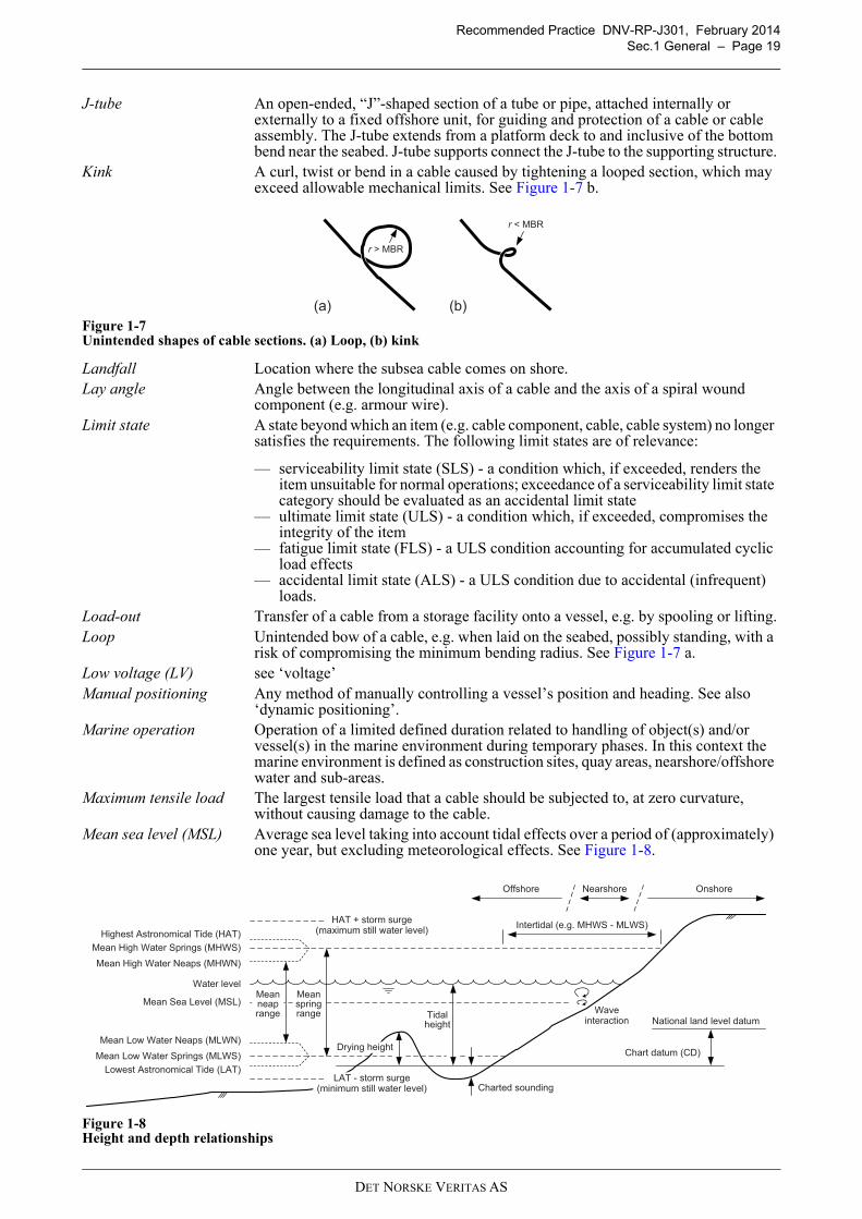
Kink A curl, twist or bend in a cable caused by tightening a looped section, which may exceed allowable mechanical limits. See Figure 1-7 b.
Figure 1-7Unintended shapes of cable sections. (a) Loop, (b) kink
Landfall Location where the subsea cable comes on shore.Lay angle Angle between the longitudinal axis of a cable and the axis of a spiral wound
component (e.g. armour wire).Limit state A state beyond which an item (e.g. cable component, cable, cable system) no longer
satisfies the requirements. The following limit states are of relevance:
— serviceability limit state (SLS) - a condition which, if exceeded, renders the item unsuitable for normal operations; exceedance of a serviceability limit state category should be evaluated as an accidental limit state
— ultimate limit state (ULS) - a condition which, if exceeded, compromises the integrity of the item
— fatigue limit state (FLS) - a ULS condition accounting for accumulated cyclic load effects
— accidental limit state (ALS) - a ULS condition due to accidental (infrequent) loads.
Load-out Transfer of a cable from a storage facility onto a vessel, e.g. by spooling or lifting.Loop Unintended bow of a cable, e.g. when laid on the seabed, possibly standing, with a
risk of compromising the minimum bending radius. See Figure 1-7 a.Low voltage (LV) see ‘voltage’Manual positioning Any method of manually controlling a vessel’s position and heading. See also
‘dynamic positioning’.Marine operation Operation of a limited defined duration related to handling of object(s) and/or
vessel(s) in the marine environment during temporary phases. In this context the marine environment is defined as construction sites, quay areas, nearshore/offshore water and sub-areas.
Maximum tensile load The largest tensile load that a cable should be subjected to, at zero curvature, without causing damage to the cable.
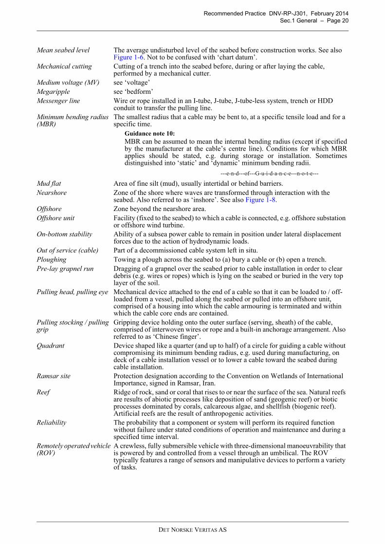
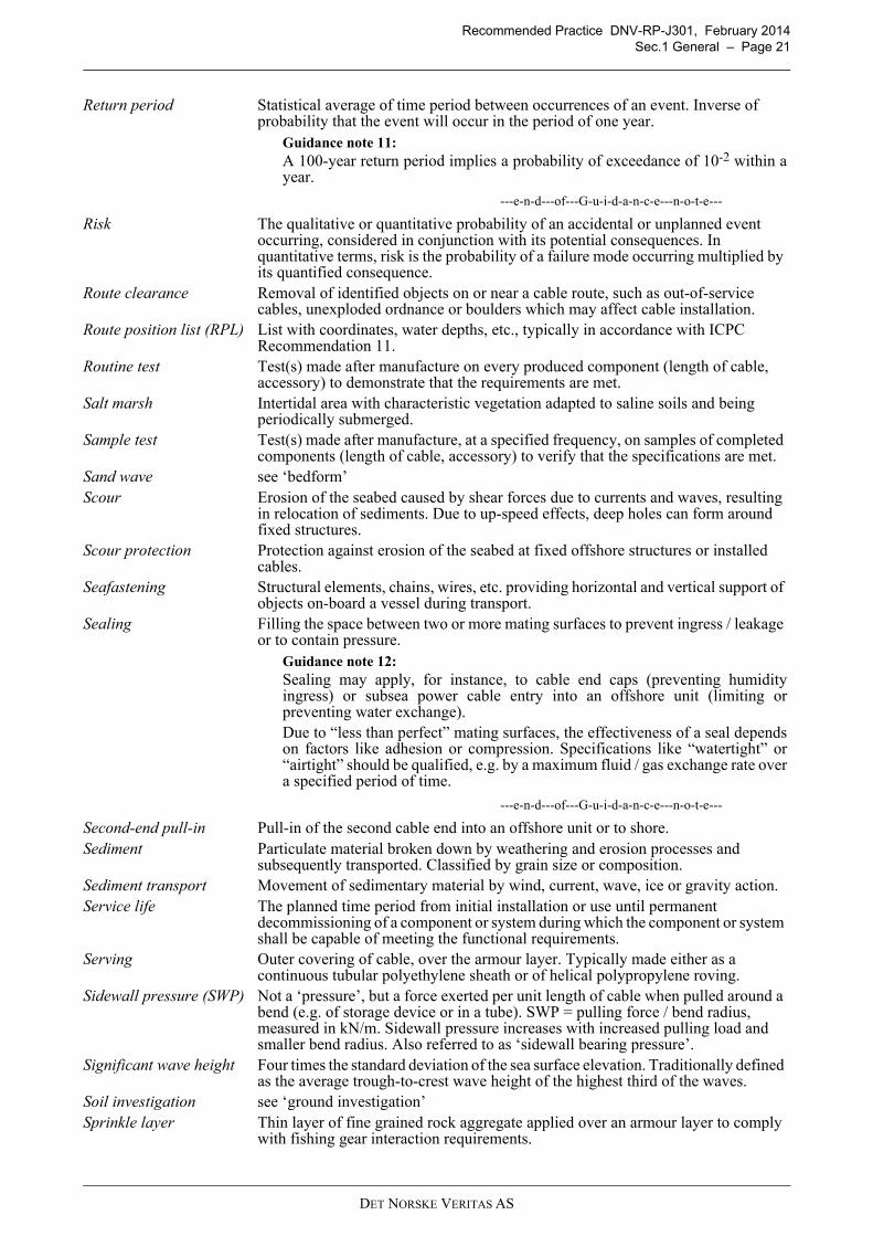
Mean sea level (MSL) Average sea level taking into account tidal effects over a period of (approximately) one year, but excluding meteorological effects. See Figure 1-8.
Figure 1-8Height and depth relationships
1.7
(a)
r > MBR
(b)
r < MBR
Highest Astronomical Tide (HAT)
Mean High Water Springs (MHWS)
Mean High Water Neaps (MHWN)
Water level
Mean Sea Level (MSL)
Mean Low Water Neaps (MLWN)
Mean Low Water Springs (MLWS)
Lowest Astronomical Tide (LAT)
Chart datum (CD)Drying height
Charted sounding
National land level datum
Meanspringrange
Meanneaprange Tidal
height
HAT + storm surge(maximum still water level)
LAT - storm surge(minimum still water level)
OnshoreOffshore Nearshore
Intertidal (e.g. MHWS - MLWS)
Waveinteraction
DET NORSKE VERITAS AS
Recommended Practice DNV-RP-J301, February 2014
Sec.1 General – Page 20
Mean seabed level The average undisturbed level of the seabed before construction works. See also Figure 1-6. Not to be confused with ‘chart datum’.
Mechanical cutting Cutting of a trench into the seabed before, during or after laying the cable, performed by a mechanical cutter.
Medium voltage (MV) see ‘voltage’Megaripple see ‘bedform’Messenger line Wire or rope installed in an I-tube, J-tube, J-tube-less system, trench or HDD
conduit to transfer the pulling line.Minimum bending radius (MBR)
The smallest radius that a cable may be bent to, at a specific tensile load and for a specific time.
Guidance note 10:
MBR can be assumed to mean the internal bending radius (except if specifiedby the manufacturer at the cable’s centre line). Conditions for which MBRapplies should be stated, e.g. during storage or installation. Sometimesdistinguished into ‘static’ and ‘dynamic’ minimum bending radii.
---e-n-d---of---G-u-i-d-a-n-c-e---n-o-t-e---
Mud flat Area of fine silt (mud), usually intertidal or behind barriers.Nearshore Zone of the shore where waves are transformed through interaction with the
seabed. Also referred to as ‘inshore’. See also Figure 1-8.Offshore Zone beyond the nearshore area.Offshore unit Facility (fixed to the seabed) to which a cable is connected, e.g. offshore substation
or offshore wind turbine.On-bottom stability Ability of a subsea power cable to remain in position under lateral displacement
forces due to the action of hydrodynamic loads.Out of service (cable) Part of a decommissioned cable system left in situ.Ploughing Towing a plough across the seabed to (a) bury a cable or (b) open a trench.Pre-lay grapnel run Dragging of a grapnel over the seabed prior to cable installation in order to clear
debris (e.g. wires or ropes) which is lying on the seabed or buried in the very top layer of the soil.
Pulling head, pulling eye Mechanical device attached to the end of a cable so that it can be loaded to / off-loaded from a vessel, pulled along the seabed or pulled into an offshore unit, comprised of a housing into which the cable armouring is terminated and within which the cable core ends are contained.
Pulling stocking / pulling grip
Gripping device holding onto the outer surface (serving, sheath) of the cable, comprised of interwoven wires or rope and a built-in anchorage arrangement. Also referred to as ‘Chinese finger’.
Quadrant Device shaped like a quarter (and up to half) of a circle for guiding a cable without compromising its minimum bending radius, e.g. used during manufacturing, on deck of a cable installation vessel or to lower a cable toward the seabed during cable installation.
Ramsar site Protection designation according to the Convention on Wetlands of International Importance, signed in Ramsar, Iran.
Reef Ridge of rock, sand or coral that rises to or near the surface of the sea. Natural reefs are results of abiotic processes like deposition of sand (geogenic reef) or biotic processes dominated by corals, calcareous algae, and shellfish (biogenic reef). Artificial reefs are the result of anthropogenic activities.
Reliability The probability that a component or system will perform its required function without failure under stated conditions of operation and maintenance and during a specified time interval.
Remotely operated vehicle (ROV)
A crewless, fully submersible vehicle with three-dimensional manoeuvrability that is powered by and controlled from a vessel through an umbilical. The ROV typically features a range of sensors and manipulative devices to perform a variety of tasks.
DET NORSKE VERITAS AS
Recommended Practice DNV-RP-J301, February 2014
Sec.1 General – Page 21
Return period Statistical average of time period between occurrences of an event. Inverse of probability that the event will occur in the period of one year.
Guidance note 11:
A 100-year return period implies a probability of exceedance of 10-2 within ayear.
---e-n-d---of---G-u-i-d-a-n-c-e---n-o-t-e---
Risk The qualitative or quantitative probability of an accidental or unplanned event occurring, considered in conjunction with its potential consequences. In quantitative terms, risk is the probability of a failure mode occurring multiplied by its quantified consequence.
Route clearance Removal of identified objects on or near a cable route, such as out-of-service cables, unexploded ordnance or boulders which may affect cable installation.
Route position list (RPL) List with coordinates, water depths, etc., typically in accordance with ICPC Recommendation 11.
Routine test Test(s) made after manufacture on every produced component (length of cable, accessory) to demonstrate that the requirements are met.
Salt marsh Intertidal area with characteristic vegetation adapted to saline soils and being periodically submerged.
Sample test Test(s) made after manufacture, at a specified frequency, on samples of completed components (length of cable, accessory) to verify that the specifications are met.
Sand wave see ‘bedform’Scour Erosion of the seabed caused by shear forces due to currents and waves, resulting
in relocation of sediments. Due to up-speed effects, deep holes can form around fixed structures.
Scour protection Protection against erosion of the seabed at fixed offshore structures or installed cables.
Seafastening Structural elements, chains, wires, etc. providing horizontal and vertical support of objects on-board a vessel during transport.
Sealing Filling the space between two or more mating surfaces to prevent ingress / leakage or to contain pressure.
Guidance note 12:
Sealing may apply, for instance, to cable end caps (preventing humidityingress) or subsea power cable entry into an offshore unit (limiting orpreventing water exchange).Due to “less than perfect” mating surfaces, the effectiveness of a seal dependson factors like adhesion or compression. Specifications like “watertight” or“airtight” should be qualified, e.g. by a maximum fluid / gas exchange rate overa specified period of time.
---e-n-d---of---G-u-i-d-a-n-c-e---n-o-t-e---
Second-end pull-in Pull-in of the second cable end into an offshore unit or to shore.Sediment Particulate material broken down by weathering and erosion processes and
subsequently transported. Classified by grain size or composition.Sediment transport Movement of sedimentary material by wind, current, wave, ice or gravity action.Service life The planned time period from initial installation or use until permanent
decommissioning of a component or system during which the component or system shall be capable of meeting the functional requirements.
Serving Outer covering of cable, over the armour layer. Typically made either as a continuous tubular polyethylene sheath or of helical polypropylene roving.
Sidewall pressure (SWP) Not a ‘pressure’, but a force exerted per unit length of cable when pulled around a bend (e.g. of storage device or in a tube). SWP = pulling force / bend radius, measured in kN/m. Sidewall pressure increases with increased pulling load and smaller bend radius. Also referred to as ‘sidewall bearing pressure’.
Significant wave height Four times the standard deviation of the sea surface elevation. Traditionally defined as the average trough-to-crest wave height of the highest third of the waves.
Soil investigation see ‘ground investigation’Sprinkle layer Thin layer of fine grained rock aggregate applied over an armour layer to comply
with fishing gear interaction requirements.
DET NORSKE VERITAS AS
Recommended Practice DNV-RP-J301, February 2014
Sec.1 General – Page 22
Storm surge Change in sea level caused by meteorological forcing (wind, atmospheric pressure) on the sea surface, positive (rise) or negative (fall).
Tensile strength Ability of a cable to withstand tensile loads.Termination Connection between cable and equipment or panels, including for instance:
— mechanical termination - fixing of cable armouring, e.g. by hang-off— electrical cable termination - device fitted to the end of a cable core ensuring
electrical connection and maintaining the insulation— optical fibre termination - connection of optical fibres to connectors and patch
panels.Thermal conductivity k A material’s ability to conduct heat, expressed in W m-1 K-1.Thermal convection Heat transfer by transport of energy through fluid motion.Thermal diffusivity α A measure of thermal inertia, equal to k / (ρ·cp), expressed in m2 s-1.Thermal resistivity ρT A material’s ability to resist heat flow, expressed in K m W-1.Torsional balance Cable characteristic achieved by its design, frequently by two armour layers
applied in opposite directions, such that axial loads do not induce significant twist or torsional loads in the cable, see [4.4.1.6].
Touch-down point Point where, during installation, the cable first touches the seabed. Trefoil Arrangement of three single cores of 3-phase AC systems in a triangular formation.Trenching Opening of a trench for simultaneous or subsequent burial of a cable.Turntable A circular, large diameter horizontal rotating platform with an active drive system on
which cable is stored and from which it is deployed. See Figure 1-5 e and Figure 1-5 f.Guidance note 13:
The term ‘turntable’ is often interchangeably used with ‘carousel’. Sometimesa distinction is made in that a turntable with side walls is referred to as‘carousel’, while a turntable without side walls is simply referred to as‘turntable’.
---e-n-d---of---G-u-i-d-a-n-c-e---n-o-t-e---
Type test Test(s) made on components (cable, accessory) to verify their properties prior to supplying them on a general commercial basis.
Unexploded ordnance (UXO)
Explosive ordnance that has or has not been primed, fused or otherwise prepared for use and which has been fired, dropped, launched, projected or placed in such a manner as to constitute a hazard to personnel or material and remains unexploded either through malfunction, design or for any other reason.
Vessel Barge, ship, tug, mobile offshore unit, crane vessel or other ship-shaped unit involved in a marine operation.
Voltage Electromotive force or potential difference expressed in volts:
— low voltage (LV), < 1 kV— medium voltage (MV), here e.g. 33 kV AC— high voltage (HV), in general ≥ 1 kV, here e.g. 132, 150 or 220 kV AC.
Guidance note 14:
In general, any voltage ≥ 1 kV can be referred to as ‘high voltage’. The term‘medium voltage’ is frequently used in wind energy applications whenreferring to the voltage level in the array cabling between wind turbines. Wherethe distinction between MV and HV is not relevant, ‘high voltage’ (as opposedto ‘HV’) is used in this recommended practice.
---e-n-d---of---G-u-i-d-a-n-c-e---n-o-t-e---
Vortex induced vibration (VIV)
Motions induced on structural elements or horizontal / vertical cable sections interacting with currents, generated by, or the motion generating, periodical irregularities in the flow.
DET NORSKE VERITAS AS
Recommended Practice DNV-RP-J301, February 2014
Sec.1 General – Page 23
1.4 Abbreviations and symbols
1.4.1 Abbreviations
Water depth Still water level to seabed distance. In fluid mud, a ‘nautical depth’ is defined as the vertical distance between the water surface and the level where seabed characteristics reach a limit beyond which contact of a vessel’s keel causes damage or unacceptable effects on controllability.
Guidance note 15:
The distinction between “shallow” and “deep” water is context-specific. In thisrecommended practice, “very shallow” generally means up to 20 m waterdepth, “shallow” up to 50 m, “deeper” more than 50 m and “deep” more than100 m.
---e-n-d---of---G-u-i-d-a-n-c-e---n-o-t-e---
Weather restricted operations
Operations with defined restrictions to the characteristic environmental conditions, planned to be performed within the period of reliable weather forecasts.
Weather window Period of time for which the environmental criteria are below a defined level (the operational limiting criteria).
A&R Abandonment and RecoveryAC Alternating CurrentA/C Alter CourseAIS Automatic Identification SystemALARP As Low As Reasonably PracticableALS Accidental Limit StateBPI Burial Protection IndexBSH Bundesamt für Seeschifffahrt und Hydrographie (Federal Maritime and Hydrographic Agency,
Germany)CAR Construction All Risk (insurance policy)CD Chart DatumCIGRÉ Conseil International des Grands Réseaux Électriques (International Council on Large Electric
Systems)CIRIA Construction Industry Research and Information AssociationCLB Cable Laying BargeCLV Cable Laying VesselCPS Cable Protection SystemCPT Cone Penetration TestDC Direct CurrentDNV Det Norske VeritasDP Dynamic Positioning, Dynamically PositionedDSS Distributed Strain SensingDTS Distributed Temperature SensingEEZ Exclusive Economic ZoneEIA Environmental Impact AssessmentEPR Ethylene Propylene RubberFLS Fatigue Limit StateFMEA Failure Mode and Effect AnalysisGIS Geographical Information SystemHAT Highest Astronomical TideHAZID Hazard IdentificationHAZOP Hazard and OperabilityHDD Horizontal Directional DrillingHSE Health, Safety, EnvironmentHV High Voltage
DET NORSKE VERITAS AS
Recommended Practice DNV-RP-J301, February 2014
Sec.1 General – Page 24
1.4.2 Symbols
HVDC High Voltage Direct CurrentICPC International Cable Protection CommitteeIEC International Electrotechnical CommissionIMCA International Marine Contractors AssociationIMO International Maritime OrganizationISO International Organization for StandardizationITU International Telecommunication UnionLAT Lowest Astronomical TideLV Low VoltageMBR Minimum Bending RadiusMCD Minimum Coiling DiameterMV Medium VoltageMWS Marine Warranty Survey, Marine Warranty SurveyorO&M Operation and MaintenanceOAR Operating All Risk (insurance policy)OSIG Offshore Site Investigation and Geotechnics CommitteeOTDR Optical Time Domain Reflectometry / ReflectometerPD Partial DischargePLB Post Lay BurialPLGR Pre-Lay Grapnel RunPPE Personal Protective EquipmentQA Quality AssuranceQRA Quantitative Risk Assessmentrms root mean squareROV Remotely Operated VehicleRPL Route Position ListRQD Rock Quality DesignationSCADA Supervisory Control and Data AcquisitionSI Système International d’ Unités (International System of Units)SLB Simultaneous Lay and BurialSLS Serviceability Limit StateSOLAS Safety Of Life At SeaSPT Standard Penetration TestSWP Sidewall PressureTDR Time Domain Reflectometry / ReflectometerTMS Tether Management SystemULS Ultimate Limit StateUN United NationsUNCLOS United Nations Convention on the Law of the SeaUV UltravioletUXO Unexploded OrdnanceVIV Vortex Induced VibrationVLF Very Low FrequencyXLPE Cross-Linked Poly-Ethylene
A Area (m2)cp Specific heat capacity (J kg-1 K-1)di Inner diameter (m)do Outer diameter (m)
DET NORSKE VERITAS AS
Recommended Practice DNV-RP-J301, February 2014
Sec.1 General – Page 25
F Force (N)f Frequency (Hz)h Height, depth (m)I Electrical current (A)k Thermal conductivity (W m-1 K-1)l Distance (m)M Moment (Nm)P Power (W)R Electrical resistance (Ω)Q Heat (J)r Radius (m)T Temperature (K)T Tension (N)TC Contingency time (h)TPOP Planned operation period (h)TR Operation reference period (h)TSafe Time to safely cease operation (h)TWF Weather forecast interval (h)t Thickness (m)t Time (s)U Rated voltage between two phases (V)U0 Rated voltage between phase and neutral (V)Um Maximum voltage between two phases (V)Up Impulse withstand voltage (V)V Volume (m3)α Thermal diffusivity (m2 s-1)δ Loss angle (°)θ Lay angle for armour application (°)ϑ Temperature (°C), where ϑ = T - T0 with T0 = 273.15 Kρ Density (kg m-3)ρT Thermal resistivity (K m W-1)
DET NORSKE VERITAS AS
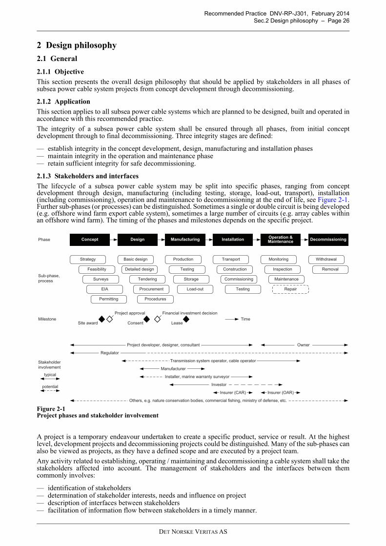
Recommended Practice DNV-RP-J301, February 2014
Sec.2 Design philosophy – Page 26
2 Design philosophy
2.1 General
2.1.1 Objective
This section presents the overall design philosophy that should be applied by stakeholders in all phases ofsubsea power cable system projects from concept development through decommissioning.
2.1.2 Application
This section applies to all subsea power cable systems which are planned to be designed, built and operated inaccordance with this recommended practice.
The integrity of a subsea power cable system shall be ensured through all phases, from initial conceptdevelopment through to final decommissioning. Three integrity stages are defined:
— establish integrity in the concept development, design, manufacturing and installation phases— maintain integrity in the operation and maintenance phase— retain sufficient integrity for safe decommissioning.
2.1.3 Stakeholders and interfaces
The lifecycle of a subsea power cable system may be split into specific phases, ranging from conceptdevelopment through design, manufacturing (including testing, storage, load-out, transport), installation(including commissioning), operation and maintenance to decommissioning at the end of life, see Figure 2-1.Further sub-phases (or processes) can be distinguished. Sometimes a single or double circuit is being developed(e.g. offshore wind farm export cable system), sometimes a large number of circuits (e.g. array cables withinan offshore wind farm). The timing of the phases and milestones depends on the specific project.
Figure 2-1Project phases and stakeholder involvement
A project is a temporary endeavour undertaken to create a specific product, service or result. At the highestlevel, development projects and decommissioning projects could be distinguished. Many of the sub-phases canalso be viewed as projects, as they have a defined scope and are executed by a project team.
Any activity related to establishing, operating / maintaining and decommissioning a cable system shall take thestakeholders affected into account. The management of stakeholders and the interfaces between themcommonly involves:
— identification of stakeholders— determination of stakeholder interests, needs and influence on project— description of interfaces between stakeholders— facilitation of information flow between stakeholders in a timely manner.
DesignOperation & Maintenance
Installation DecommissioningManufacturingConceptPhase
Procurement
Sub-phase,
process
Testing
Storage
Transport
Commissioning
Inspection
Repair
Maintenance
Monitoring Withdrawal
Removal
Basic design
Detailed designFeasibility
Strategy
EIA
Surveys
Permitting
Milestone
Stakeholder
involvement
Production
Construction
Testing
Site award Consent Lease
Financial investment decisionProject approval
Regulator
Project developer, designer, consultant Owner
Manufacturer
Insurer (CAR) Insurer (OAR)
Others, e.g. nature conservation bodies, commercial fishing, ministry of defense, etc.
typical
potential
Tendering
Load-out
Procedures
Time
Installer, marine warranty surveyor
Investor
Transmission system operator, cable operator
DET NORSKE VERITAS AS
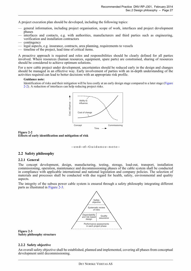
Recommended Practice DNV-RP-J301, February 2014
Sec.2 Design philosophy – Page 27
A project execution plan should be developed, including the following topics:
— general information, including project organisation, scope of work, interfaces and project developmentphases
— interfaces and contacts, e.g. with authorities, manufacturers and third parties such as engineering,verification and installation contractors
— contingency— legal aspects, e.g. insurance, contracts, area planning, requirements to vessels— timeline of the project, lead time of critical items.
A proactive approach is required and roles and responsibilities should be clearly defined for all partiesinvolved. Where resources (human resources, equipment, spare parts) are constrained, sharing of resourcesshould be considered to achieve optimum solutions.
For a new cable project under development, uncertainties should be reduced early in the design and changesshould be managed in an effective way. Early involvement of parties with an in-depth understanding of theactivities required can lead to better decisions with an appropriate risk profile.
Guidance note:
Identification of risks and their mitigation will be less costly at an early design stage compared to a later stage (Figure2-2). A reduction of interfaces can help reducing project risks.
Figure 2-2Effects of early identification and mitigation of risk
---e-n-d---of---G-u-i-d-a-n-c-e---n-o-t-e---
2.2 Safety philosophy
2.2.1 General
The concept development, design, manufacturing, testing, storage, load-out, transport, installationcommissioning, operation, maintenance and decommissioning phases of the cable system shall be conductedin compliance with applicable international and national legislation and company policies. The selection ofmaterials and processes shall be conducted with due regard for health, safety, environmental and qualityaspects.
The integrity of the subsea power cable system is ensured through a safety philosophy integrating differentparts as illustrated in Figure 2-3.
Figure 2-3Safety philosophy structure
2.2.2 Safety objective
An overall safety objective shall be established, planned and implemented, covering all phases from conceptualdevelopment until decommissioning.
Time
Co
st,
in
flue
nce
Ability to
influence
Cost of change
Concept Commissioning
Safetyobjective
Dependability and risk based
design
Systematic reviewof risks
Quality assurance
Performance assessmentsin each project phase
DET NORSKE VERITAS AS
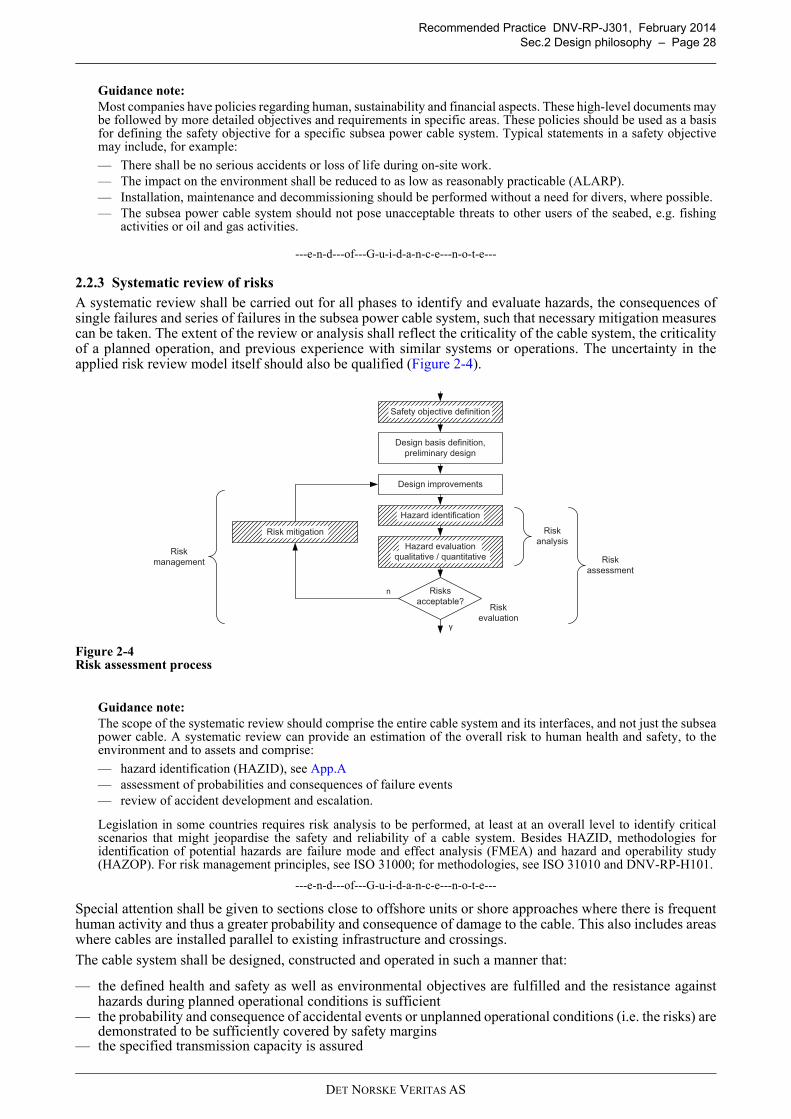
Recommended Practice DNV-RP-J301, February 2014
Sec.2 Design philosophy – Page 28
Guidance note:
Most companies have policies regarding human, sustainability and financial aspects. These high-level documents maybe followed by more detailed objectives and requirements in specific areas. These policies should be used as a basisfor defining the safety objective for a specific subsea power cable system. Typical statements in a safety objectivemay include, for example:
— There shall be no serious accidents or loss of life during on-site work.— The impact on the environment shall be reduced to as low as reasonably practicable (ALARP).— Installation, maintenance and decommissioning should be performed without a need for divers, where possible.— The subsea power cable system should not pose unacceptable threats to other users of the seabed, e.g. fishing
activities or oil and gas activities.
---e-n-d---of---G-u-i-d-a-n-c-e---n-o-t-e---
2.2.3 Systematic review of risks
A systematic review shall be carried out for all phases to identify and evaluate hazards, the consequences ofsingle failures and series of failures in the subsea power cable system, such that necessary mitigation measurescan be taken. The extent of the review or analysis shall reflect the criticality of the cable system, the criticalityof a planned operation, and previous experience with similar systems or operations. The uncertainty in theapplied risk review model itself should also be qualified (Figure 2-4).
Figure 2-4Risk assessment process
Guidance note:
The scope of the systematic review should comprise the entire cable system and its interfaces, and not just the subseapower cable. A systematic review can provide an estimation of the overall risk to human health and safety, to theenvironment and to assets and comprise:
— hazard identification (HAZID), see App.A— assessment of probabilities and consequences of failure events— review of accident development and escalation.
Legislation in some countries requires risk analysis to be performed, at least at an overall level to identify criticalscenarios that might jeopardise the safety and reliability of a cable system. Besides HAZID, methodologies foridentification of potential hazards are failure mode and effect analysis (FMEA) and hazard and operability study(HAZOP). For risk management principles, see ISO 31000; for methodologies, see ISO 31010 and DNV-RP-H101.
---e-n-d---of---G-u-i-d-a-n-c-e---n-o-t-e---
Special attention shall be given to sections close to offshore units or shore approaches where there is frequenthuman activity and thus a greater probability and consequence of damage to the cable. This also includes areaswhere cables are installed parallel to existing infrastructure and crossings.
The cable system shall be designed, constructed and operated in such a manner that:
— the defined health and safety as well as environmental objectives are fulfilled and the resistance againsthazards during planned operational conditions is sufficient
— the probability and consequence of accidental events or unplanned operational conditions (i.e. the risks) aredemonstrated to be sufficiently covered by safety margins
— the specified transmission capacity is assured
2.4
Design improvements
Risks
acceptable?
n
y
Safety objective definition
Hazard identification
qualitative / quantitative
Hazard evaluation
Design basis definition,
preliminary design
Risk
assessment
Risk
analysis
Risk
evaluation
Risk mitigation
Risk
management
DET NORSKE VERITAS AS
Recommended Practice DNV-RP-J301, February 2014
Sec.2 Design philosophy – Page 29
— system layout meets the requirements imposed by the systematic review.
2.2.4 Dependability and risk based design
Safety, environmental performance and functionality of the overall cable system can be ensured by applicationof dependability and risk based design methodologies, see [2.3]. The overall cable system should be assessedbased on failure consequences and their probability to demonstrate that project objectives will be met.
Guidance note:
For guidance on third party damage to underground and subsea cables, see CIGRÉ Technical Brochure 398.
---e-n-d---of---G-u-i-d-a-n-c-e---n-o-t-e---
2.2.5 Quality assurance
2.2.5.1 General
The safety philosophy requires that gross (human) errors shall be controlled by requirements for organisationof work, competence of persons performing the work, verification of work, and quality assurance during allrelevant phases.
Documented quality systems shall be applied by developers / operators and other parties involved to ensure thatproducts, processes and services are in compliance with the requirements.
The developer / operator of a cable system and other parties involved (e.g. designers, manufacturers andinstallers) should establish quality objectives. The developer / operator should obtain assurance that intendedquality is being, or will be, achieved.
Non-conformities can reflect systematic deviations from procedures and/or inadequate workmanship andshould initiate:
— investigation into the immediate (and possibly root) causes of the non-conformities— corrective action to establish possible acceptability of products— preventive action to prevent re-occurrence of similar non-conformities— re-assessment of the quality system.
Quality assurance during the manufacturing and installation phases shall be performed by the developer /operator or an appointed party. The extent of quality assurance shall be sufficient to establish that specifiedrequirements are fulfilled and that the intended quality level is maintained.
2.2.5.2 Marine warranty survey
A Marine Warranty Surveyor (MWS) performs quality surveillance for marine operations. Where MWSservices are planned to be used, a scope of work leading to approval by the MWS shall be created. The scopeof work may include, subject to project-specific agreements, review and approval for cable and/or cablecomponents:
— risk assessments, operating and installation procedures, contingency procedures— transport, installation and lift analyses; weather restricted operations— vessels and equipment used in the installation process— land transport— load-out to transport vessel, inter-vessel transfer— transport to installation site— installation, burial or other cable protection.
The scope of work may also, subject to project-specific agreements, include attendance of cable testing at thefactory, termination works and testing before / after termination.
The MWS work will be carried out by means of review of documentation and analyses, independentcalculations as well as surveys. The MWS shall establish uniform acceptance criteria covering all operationsunder the scope of work and communicate these to the parties concerned.
2.3 Design format
2.3.1 Approach
Items of a cable system, including their installation and operation, can be designed using various methods,including deterministic, probabilistic and testing-based approaches as well as combinations of these.
Guidance note:
Power cables are commonly designed based on material properties which were established through testing and provenin qualification processes. HV cables systems should be qualified as a whole to ensure overall system reliability.
---e-n-d---of---G-u-i-d-a-n-c-e---n-o-t-e---
DET NORSKE VERITAS AS
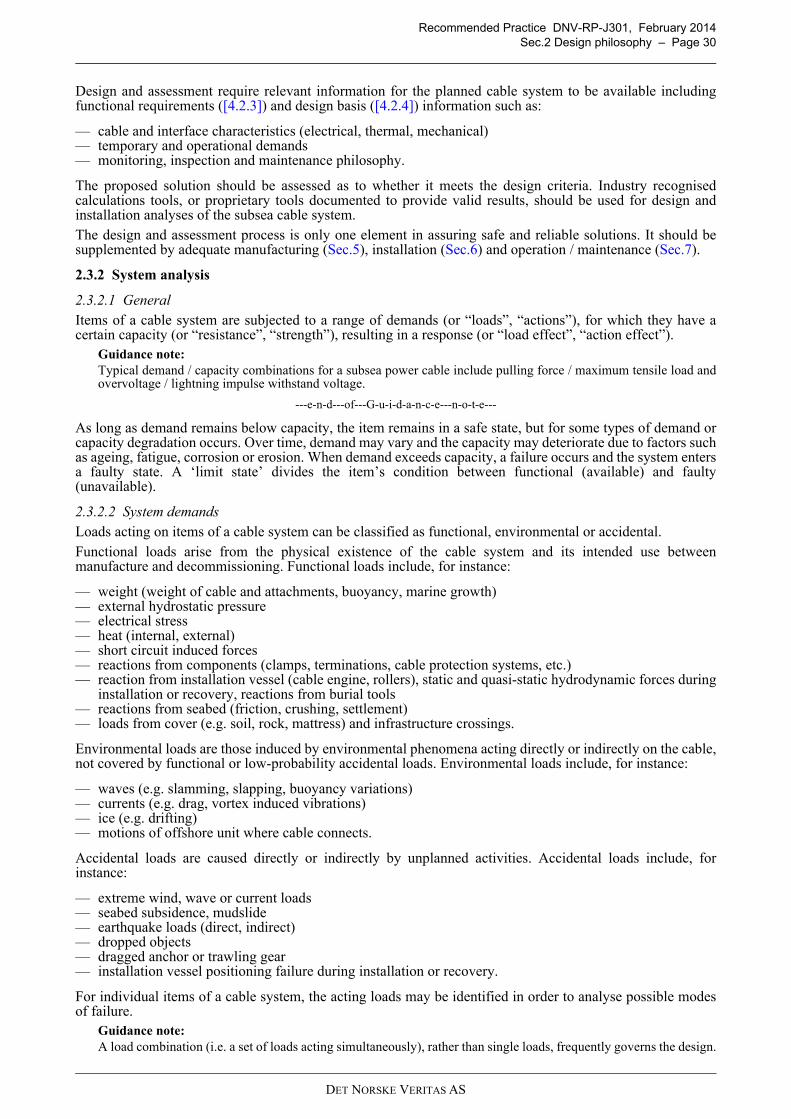
Recommended Practice DNV-RP-J301, February 2014
Sec.2 Design philosophy – Page 30
Design and assessment require relevant information for the planned cable system to be available includingfunctional requirements ([4.2.3]) and design basis ([4.2.4]) information such as:
— cable and interface characteristics (electrical, thermal, mechanical)— temporary and operational demands— monitoring, inspection and maintenance philosophy.
The proposed solution should be assessed as to whether it meets the design criteria. Industry recognisedcalculations tools, or proprietary tools documented to provide valid results, should be used for design andinstallation analyses of the subsea cable system.
The design and assessment process is only one element in assuring safe and reliable solutions. It should besupplemented by adequate manufacturing (Sec.5), installation (Sec.6) and operation / maintenance (Sec.7).
2.3.2 System analysis
2.3.2.1 General
Items of a cable system are subjected to a range of demands (or “loads”, “actions”), for which they have acertain capacity (or “resistance”, “strength”), resulting in a response (or “load effect”, “action effect”).
Guidance note:
Typical demand / capacity combinations for a subsea power cable include pulling force / maximum tensile load andovervoltage / lightning impulse withstand voltage.
---e-n-d---of---G-u-i-d-a-n-c-e---n-o-t-e---
As long as demand remains below capacity, the item remains in a safe state, but for some types of demand orcapacity degradation occurs. Over time, demand may vary and the capacity may deteriorate due to factors suchas ageing, fatigue, corrosion or erosion. When demand exceeds capacity, a failure occurs and the system entersa faulty state. A ‘limit state’ divides the item’s condition between functional (available) and faulty(unavailable).
2.3.2.2 System demands
Loads acting on items of a cable system can be classified as functional, environmental or accidental.
Functional loads arise from the physical existence of the cable system and its intended use betweenmanufacture and decommissioning. Functional loads include, for instance:
— weight (weight of cable and attachments, buoyancy, marine growth)— external hydrostatic pressure— electrical stress— heat (internal, external)— short circuit induced forces— reactions from components (clamps, terminations, cable protection systems, etc.)— reaction from installation vessel (cable engine, rollers), static and quasi-static hydrodynamic forces during
installation or recovery, reactions from burial tools— reactions from seabed (friction, crushing, settlement)— loads from cover (e.g. soil, rock, mattress) and infrastructure crossings.
Environmental loads are those induced by environmental phenomena acting directly or indirectly on the cable,not covered by functional or low-probability accidental loads. Environmental loads include, for instance:
— waves (e.g. slamming, slapping, buoyancy variations)— currents (e.g. drag, vortex induced vibrations)— ice (e.g. drifting)— motions of offshore unit where cable connects.
Accidental loads are caused directly or indirectly by unplanned activities. Accidental loads include, forinstance:
— extreme wind, wave or current loads— seabed subsidence, mudslide— earthquake loads (direct, indirect)— dropped objects— dragged anchor or trawling gear— installation vessel positioning failure during installation or recovery.
For individual items of a cable system, the acting loads may be identified in order to analyse possible modesof failure.
Guidance note:
A load combination (i.e. a set of loads acting simultaneously), rather than single loads, frequently governs the design.
DET NORSKE VERITAS AS
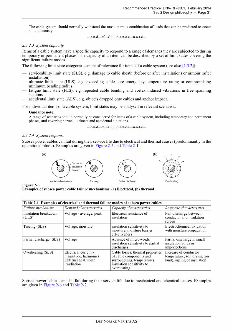
Recommended Practice DNV-RP-J301, February 2014
Sec.2 Design philosophy – Page 31
The cable system should normally withstand the most onerous combination of loads that can be predicted to occursimultaneously.
---e-n-d---of---G-u-i-d-a-n-c-e---n-o-t-e---
2.3.2.3 System capacity
Items of a cable system have a specific capacity to respond to a range of demands they are subjected to duringtemporary or permanent phases. The capacity of an item can be described by a set of limit states covering thesignificant failure modes.
The following limit state categories can be of relevance for items of a cable system (see also [1.3.2]):
— serviceability limit state (SLS), e.g. damage to cable sheath (before or after installation) or armour (afterinstallation)
— ultimate limit state (ULS), e.g. exceeding cable core emergency temperature rating or compromisingminimum bending radius
— fatigue limit state (FLS), e.g. repeated cable bending and vortex induced vibrations in free spanningsections
— accidental limit state (ALS), e.g. objects dropped onto cables and anchor impact.
For individual items of a cable system, limit states may be analysed in relevant scenarios.Guidance note:
A range of scenarios should normally be considered for items of a cable system, including temporary and permanentphases, and covering normal, ultimate and accidental situations.
---e-n-d---of---G-u-i-d-a-n-c-e---n-o-t-e---
2.3.2.4 System response
Subsea power cables can fail during their service life due to electrical and thermal causes (predominantly in theoperational phase). Examples are given in Figure 2-5 and Table 2-1.
Figure 2-5Examples of subsea power cable failure mechanisms. (a) Electrical, (b) thermal
Subsea power cables can also fail during their service life due to mechanical and chemical causes. Examplesare given in Figure 2-6 and Table 2-2.
Table 2-1 Examples of electrical and thermal failure modes of subsea power cables
Failure mechanism Demand characteristics Capacity characteristics Response characteristics
Insulation breakdown (ULS)
Voltage - average, peak Electrical resistance of insulation
Full discharge between conductor and insulation screen
Treeing (SLS) Voltage, moisture insulation sensitivity to moisture, moisture barrier effectiveness
Electrochemical oxidation with moisture propagation
Partial discharge (SLS) Voltage Absence of micro-voids, insulation sensitivity to partial discharges
Partial discharge in small insulation voids or imperfections
Overheating (SLS) Electrical current - magnitude, harmonicsExternal heat, solar irradiation
Cable losses, thermal properties of cable components and surroundings, temperatures, insulation sensitivity to overheating
Increase of conductor temperature, soil drying (on land), ageing of insulation
(a)
Insulation breakdown Treeing Partial discharge
(b)
Overheating
Conductor
Insulation
Screen
DET NORSKE VERITAS AS
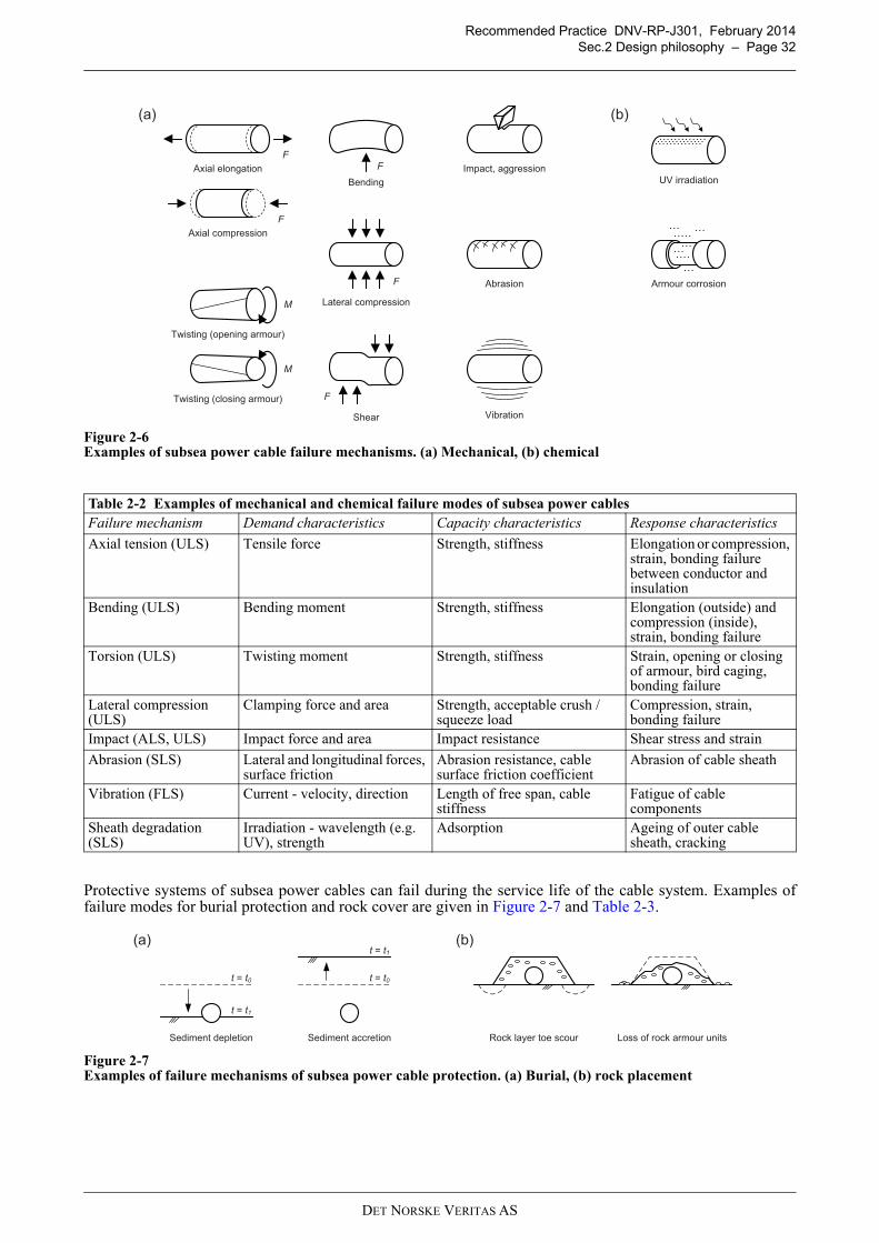
Recommended Practice DNV-RP-J301, February 2014
Sec.2 Design philosophy – Page 32
Figure 2-6Examples of subsea power cable failure mechanisms. (a) Mechanical, (b) chemical
Protective systems of subsea power cables can fail during the service life of the cable system. Examples offailure modes for burial protection and rock cover are given in Figure 2-7 and Table 2-3.
Figure 2-7Examples of failure mechanisms of subsea power cable protection. (a) Burial, (b) rock placement
Table 2-2 Examples of mechanical and chemical failure modes of subsea power cables
Failure mechanism Demand characteristics Capacity characteristics Response characteristics
Axial tension (ULS) Tensile force Strength, stiffness Elongation or compression, strain, bonding failure between conductor and insulation
Bending (ULS) Bending moment Strength, stiffness Elongation (outside) and compression (inside), strain, bonding failure
Torsion (ULS) Twisting moment Strength, stiffness Strain, opening or closing of armour, bird caging, bonding failure
Lateral compression (ULS)
Clamping force and area Strength, acceptable crush / squeeze load
Compression, strain, bonding failure
Impact (ALS, ULS) Impact force and area Impact resistance Shear stress and strain
Abrasion (SLS) Lateral and longitudinal forces, surface friction
Abrasion resistance, cable surface friction coefficient
Abrasion of cable sheath
Vibration (FLS) Current - velocity, direction Length of free span, cable stiffness
Fatigue of cable components
Sheath degradation (SLS)
Irradiation - wavelength (e.g. UV), strength
Adsorption Ageing of outer cable sheath, cracking
(a)
Axial elongation
Axial compression
Bending
Twisting (opening armour)
Twisting (closing armour)
Lateral compression
Shear
Impact, aggression
Abrasion
Vibration
(b)
UV irradiation
Armour corrosion
M
M
F
F
F
F
F
(a) (b)
Sediment depletion Sediment accretion Rock layer toe scour Loss of rock armour units
t = t0
t = t1
t = t0
t = t1
DET NORSKE VERITAS AS
Recommended Practice DNV-RP-J301, February 2014
Sec.2 Design philosophy – Page 33
For individual items of a cable system, possible and credible failure modes should be identified. For thosefailure modes considered relevant, failure criteria (exceedance of capacity or critical threshold) may beformulated.
Guidance note:
Some failure modes may be allowed to occur repeatedly (generally in the SLS category), others are not acceptableeven as a single occurrence (generally in the ALS and ULS categories).For power cables, most credible failure modes are addressed by designing to applicable IEC standards and CIGRÉguidelines, combined with mechanical / electrical type and routine testing.
---e-n-d---of---G-u-i-d-a-n-c-e---n-o-t-e---
Table 2-3 Examples of failure modes of subsea power cable protection
Failure mechanism Demand characteristics Capacity characteristics Response characteristics
Sediment depletion (SLS)
Waves - height, periodCurrents - velocity, direction, turbulence
Non-cohesive soils - sediment grain size, friction angle
Reduction of soil cover, exposure to dragged and dropped objects
Sediment accretion (SLS)
Waves - height, periodCurrents - velocity, direction, turbulence
Non-cohesive soils - sediment grain size, friction angle
Increase of soil cover, reduction of cable cooling
Scour (SLS) Waves - height, periodCurrents - velocity, turbulence
Sediment grain size, structure slope and permeability
Scour in toe area, subsequent movement of rock cover
Movement of rock cover (SLS)
Waves - height, period, directionCurrents - velocity, directionAggression - impact, frequency
Rock size and density, permeability of cover layer
Rocking, sliding, lifting, rolling, loss of armour units
DET NORSKE VERITAS AS
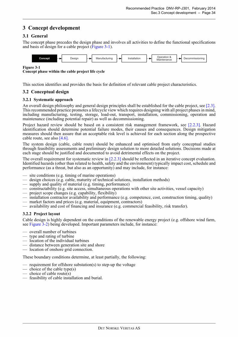
Recommended Practice DNV-RP-J301, February 2014
Sec.3 Concept development – Page 34
3.1
3 Concept development
3.1 General
The concept phase precedes the design phase and involves all activities to define the functional specificationsand basis of design for a cable project (Figure 3-1).
Figure 3-1Concept phase within the cable project life cycle
This section identifies and provides the basis for definition of relevant cable project characteristics.
3.2 Conceptual design
3.2.1 Systematic approach
An overall design philosophy and general design principles shall be established for the cable project, see [2.3].This recommended practice promotes a lifecycle view which requires designing with all project phases in mind,including manufacturing, testing, storage, load-out, transport, installation, commissioning, operation andmaintenance (including potential repair) as well as decommissioning.
Project hazard review should be based on a consistent risk management framework, see [2.2.3]. Hazardidentification should determine potential failure modes, their causes and consequences. Design mitigationmeasures should then assure that an acceptable risk level is achieved for each section along the prospectivecable route, see also [4.6].
The system design (cable, cable route) should be enhanced and optimised from early conceptual studiesthrough feasibility assessments and preliminary design solution to more detailed solutions. Decisions made ateach stage should be justified and documented to avoid detrimental effects on the project.
The overall requirement for systematic review in [2.2.3] should be reflected in an iterative concept evaluation.Identified hazards (other than related to health, safety and the environment) typically impact cost, schedule andperformance (as a threat, but also as an opportunity) and may include, for instance:
— site conditions (e.g. timing of marine operations)— design choices (e.g. cable, maturity of technical solutions, installation methods)— supply and quality of material (e.g. timing, performance)— constructability (e.g. site access, simultaneous operations with other site activities, vessel capacity)— project scope changes (e.g. capability, flexibility)— installation contractor availability and performance (e.g. competence, cost, construction timing, quality)— market factors and prices (e.g. material, equipment, contractors)— availability and cost of financing and insurance (e.g. commercial feasibility, risk transfer).
3.2.2 Project layout
Cable design is highly dependent on the conditions of the renewable energy project (e.g. offshore wind farm,see Figure 3-2) being developed. Important parameters include, for instance:
— overall number of turbines— type and rating of turbine— location of the individual turbines— distance between generation site and shore— location of onshore grid connection.
These boundary conditions determine, at least partially, the following:
— requirement for offshore substation(s) to step-up the voltage— choice of the cable type(s)— choice of cable route(s)— feasibility of cable installation and burial.
DesignConceptOperation & Maintenance
Installation DecommissioningManufacturing
DET NORSKE VERITAS AS
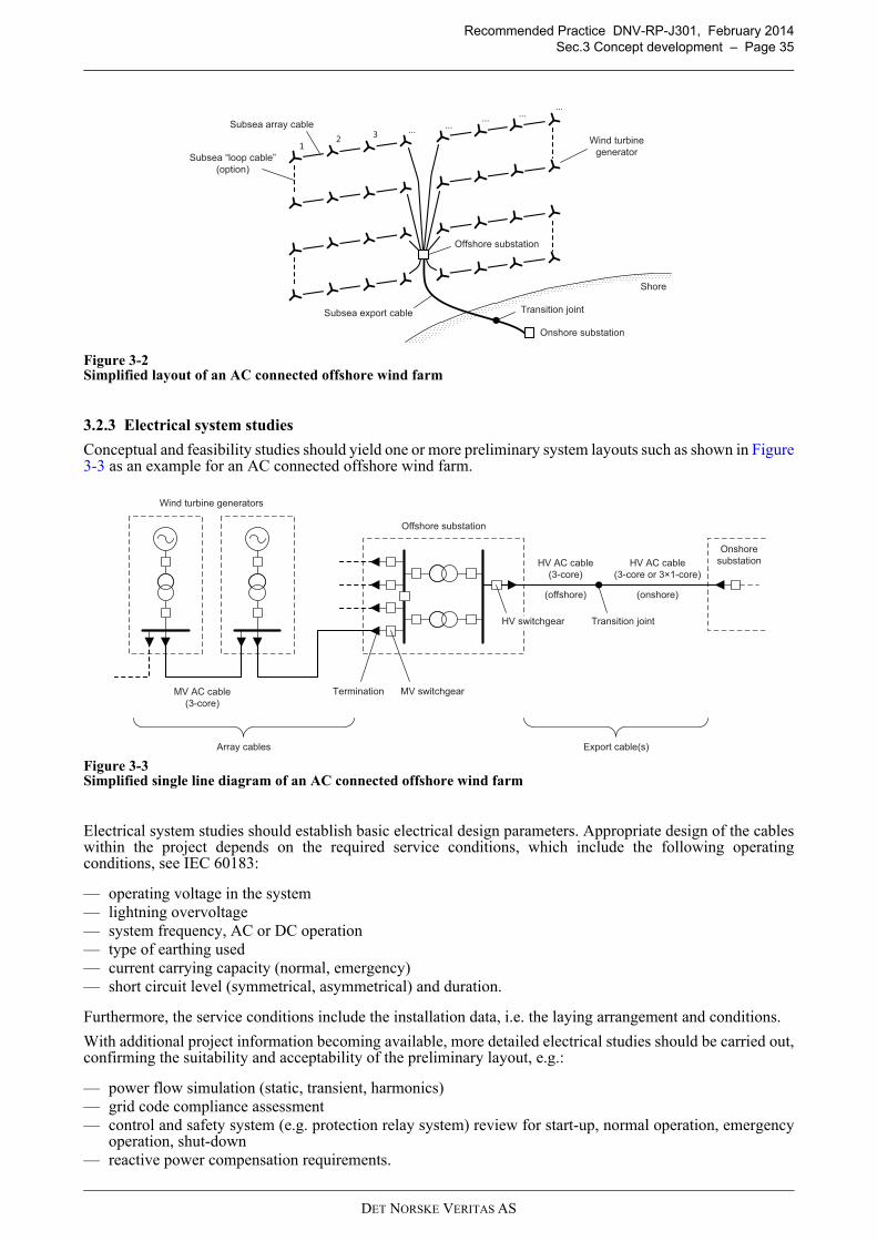
Recommended Practice DNV-RP-J301, February 2014
Sec.3 Concept development – Page 35
Figure 3-2Simplified layout of an AC connected offshore wind farm
3.2.3 Electrical system studies
Conceptual and feasibility studies should yield one or more preliminary system layouts such as shown in Figure3-3 as an example for an AC connected offshore wind farm.
Figure 3-3Simplified single line diagram of an AC connected offshore wind farm
Electrical system studies should establish basic electrical design parameters. Appropriate design of the cableswithin the project depends on the required service conditions, which include the following operatingconditions, see IEC 60183:
— operating voltage in the system— lightning overvoltage— system frequency, AC or DC operation— type of earthing used— current carrying capacity (normal, emergency)— short circuit level (symmetrical, asymmetrical) and duration.
Furthermore, the service conditions include the installation data, i.e. the laying arrangement and conditions.
With additional project information becoming available, more detailed electrical studies should be carried out,confirming the suitability and acceptability of the preliminary layout, e.g.:
— power flow simulation (static, transient, harmonics)— grid code compliance assessment— control and safety system (e.g. protection relay system) review for start-up, normal operation, emergency
operation, shut-down— reactive power compensation requirements.
Wind turbine
generator
Subsea export cable
Subsea array cable
12
3...
......
......
Onshore substation
Shore
Transition joint
Offshore substation
Subsea “loop cable”
(option)
HV AC cable
(3-core)
Offshore substation
Wind turbine generators
Onshore
substation
MV AC cable
(3-core)
MV switchgearTermination
HV switchgear Transition joint
HV AC cable
(3-core or 3×1-core)
Array cables Export cable(s)
(offshore) (onshore)
DET NORSKE VERITAS AS
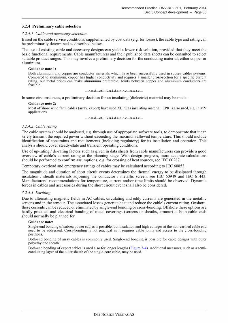
Recommended Practice DNV-RP-J301, February 2014
Sec.3 Concept development – Page 36
3.2.4 Preliminary cable selection
3.2.4.1 Cable and accessory selection
Based on the cable service conditions, supplemented by cost data (e.g. for losses), the cable type and rating canbe preliminarily determined as described below.
The use of existing cable and accessory designs can yield a lower risk solution, provided that they meet thebasic functional requirements. Cable manufacturers and their published data sheets can be consulted to selectsuitable product ranges. This may involve a preliminary decision for the conducting material, either copper oraluminium.
Guidance note 1:
Both aluminium and copper are conductor materials which have been successfully used in subsea cables systems.Compared to aluminium, copper has higher conductivity and requires a smaller cross-section for a specific currentrating, but metal prices can make aluminium preferable. Joints between copper and aluminium conductors arefeasible.
---e-n-d---of---G-u-i-d-a-n-c-e---n-o-t-e---
In some circumstances, a preliminary decision for an insulating (dielectric) material may be made.Guidance note 2:
Most offshore wind farm cables (array, export) have used XLPE as insulating material. EPR is also used, e.g. in MVapplications.
---e-n-d---of---G-u-i-d-a-n-c-e---n-o-t-e---
3.2.4.2 Cable rating
The cable system should be analysed, e.g. through use of appropriate software tools, to demonstrate that it cansafely transmit the required power without exceeding the maximum allowed temperature. This should includeidentification of constraints and requirements (including regulatory) for its installation and operation. Thisanalysis should cover steady-state and transient operating conditions.
Use of up-rating / de-rating factors such as given in data sheets from cable manufacturers can provide a goodoverview of cable’s current rating at the planning stage. With design progress, more accurate calculationsshould be performed to confirm assumptions, e.g. for crossing of heat sources, see IEC 60287.
Temporary overload and emergency ratings of cables may be calculated according to IEC 60853.
The magnitude and duration of short circuit events determines the thermal energy to be dissipated throughinsulation / sheath materials adjoining the conductor / metallic screen, see IEC 60949 and IEC 61443.Manufacturers’ recommendations for temperature, current and/or time limits should be observed. Dynamicforces in cables and accessories during the short circuit event shall also be considered.
3.2.4.3 Earthing
Due to alternating magnetic fields in AC cables, circulating and eddy currents are generated in the metallicscreens and in the armour. The associated losses generate heat and reduce the cable’s current rating. Onshore,these currents can be reduced or eliminated by single-end bonding or cross-bonding. Offshore these options arehardly practical and electrical bonding of metal coverings (screens or sheaths, armour) at both cable endsshould normally be planned for.
Guidance note:
Single-end bonding of subsea power cables is possible, but insulation and high voltages at the non-earthed cable endneed to be addressed. Cross-bonding is not practical as it requires cable joints and access to the cross-bondingpositions.Both-end bonding of array cables is commonly used. Single-end bonding is possible for cable designs with outerpolyethylene sheath.Both-end bonding of export cables is used also for longer lengths (Figure 3-4). Additional measures, such as a semi-conducting layer of the outer sheath of the single-core cable, may be used.
DET NORSKE VERITAS AS
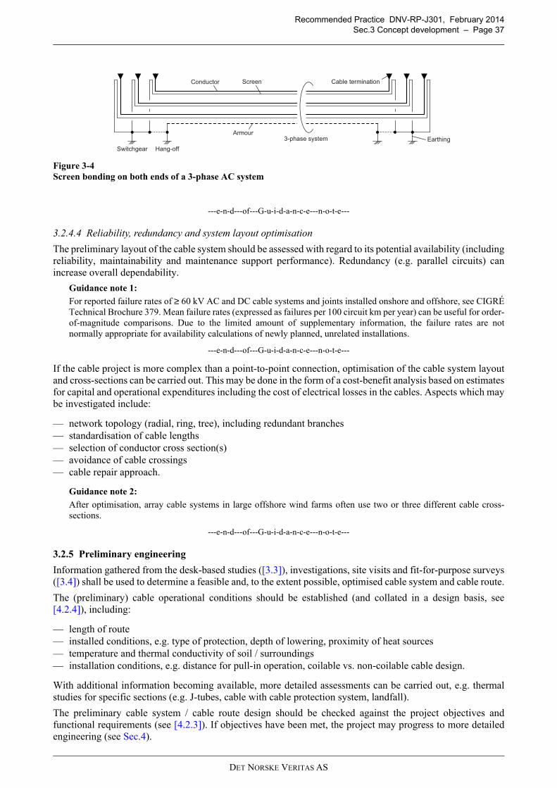
Recommended Practice DNV-RP-J301, February 2014
Sec.3 Concept development – Page 37
Figure 3-4
Screen bonding on both ends of a 3-phase AC system
---e-n-d---of---G-u-i-d-a-n-c-e---n-o-t-e---
3.2.4.4 Reliability, redundancy and system layout optimisation
The preliminary layout of the cable system should be assessed with regard to its potential availability (includingreliability, maintainability and maintenance support performance). Redundancy (e.g. parallel circuits) canincrease overall dependability.
Guidance note 1:
For reported failure rates of ≥ 60 kV AC and DC cable systems and joints installed onshore and offshore, see CIGRÉTechnical Brochure 379. Mean failure rates (expressed as failures per 100 circuit km per year) can be useful for order-of-magnitude comparisons. Due to the limited amount of supplementary information, the failure rates are notnormally appropriate for availability calculations of newly planned, unrelated installations.
---e-n-d---of---G-u-i-d-a-n-c-e---n-o-t-e---
If the cable project is more complex than a point-to-point connection, optimisation of the cable system layoutand cross-sections can be carried out. This may be done in the form of a cost-benefit analysis based on estimatesfor capital and operational expenditures including the cost of electrical losses in the cables. Aspects which maybe investigated include:
— network topology (radial, ring, tree), including redundant branches— standardisation of cable lengths— selection of conductor cross section(s)— avoidance of cable crossings— cable repair approach.
Guidance note 2:
After optimisation, array cable systems in large offshore wind farms often use two or three different cable cross-sections.
---e-n-d---of---G-u-i-d-a-n-c-e---n-o-t-e---
3.2.5 Preliminary engineering
Information gathered from the desk-based studies ([3.3]), investigations, site visits and fit-for-purpose surveys([3.4]) shall be used to determine a feasible and, to the extent possible, optimised cable system and cable route.
The (preliminary) cable operational conditions should be established (and collated in a design basis, see[4.2.4]), including:
— length of route— installed conditions, e.g. type of protection, depth of lowering, proximity of heat sources— temperature and thermal conductivity of soil / surroundings— installation conditions, e.g. distance for pull-in operation, coilable vs. non-coilable cable design.
With additional information becoming available, more detailed assessments can be carried out, e.g. thermalstudies for specific sections (e.g. J-tubes, cable with cable protection system, landfall).
The preliminary cable system / cable route design should be checked against the project objectives andfunctional requirements (see [4.2.3]). If objectives have been met, the project may progress to more detailedengineering (see Sec.4).
Cable terminationConductor Screen
Earthing3-phase system
Hang-off
Armour
Switchgear
DET NORSKE VERITAS AS
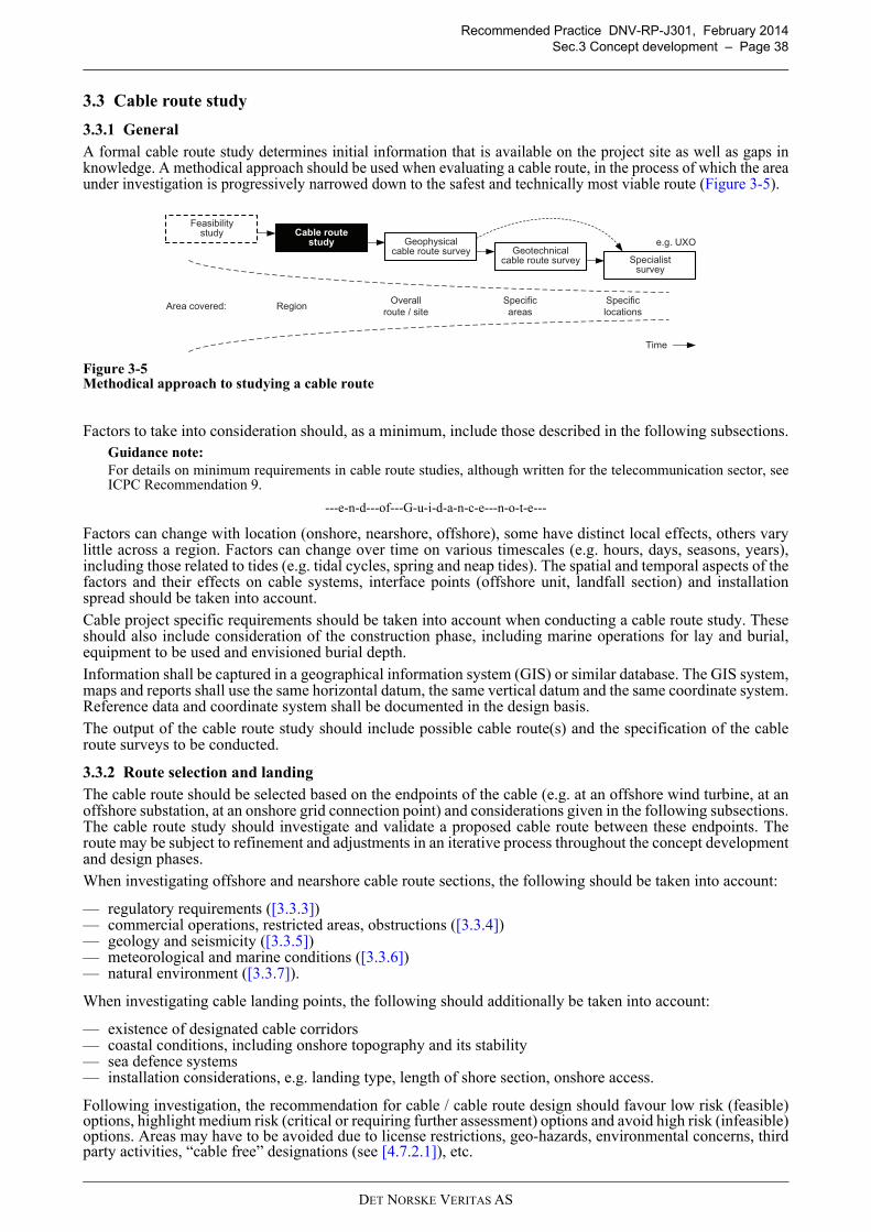
Recommended Practice DNV-RP-J301, February 2014
Sec.3 Concept development – Page 38
3.3 Cable route study
3.3.1 General
A formal cable route study determines initial information that is available on the project site as well as gaps inknowledge. A methodical approach should be used when evaluating a cable route, in the process of which the areaunder investigation is progressively narrowed down to the safest and technically most viable route (Figure 3-5).
Figure 3-5Methodical approach to studying a cable route
Factors to take into consideration should, as a minimum, include those described in the following subsections.Guidance note:
For details on minimum requirements in cable route studies, although written for the telecommunication sector, seeICPC Recommendation 9.
---e-n-d---of---G-u-i-d-a-n-c-e---n-o-t-e---
Factors can change with location (onshore, nearshore, offshore), some have distinct local effects, others varylittle across a region. Factors can change over time on various timescales (e.g. hours, days, seasons, years),including those related to tides (e.g. tidal cycles, spring and neap tides). The spatial and temporal aspects of thefactors and their effects on cable systems, interface points (offshore unit, landfall section) and installationspread should be taken into account.
Cable project specific requirements should be taken into account when conducting a cable route study. Theseshould also include consideration of the construction phase, including marine operations for lay and burial,equipment to be used and envisioned burial depth.
Information shall be captured in a geographical information system (GIS) or similar database. The GIS system,maps and reports shall use the same horizontal datum, the same vertical datum and the same coordinate system.Reference data and coordinate system shall be documented in the design basis.
The output of the cable route study should include possible cable route(s) and the specification of the cableroute surveys to be conducted.
3.3.2 Route selection and landing
The cable route should be selected based on the endpoints of the cable (e.g. at an offshore wind turbine, at anoffshore substation, at an onshore grid connection point) and considerations given in the following subsections.The cable route study should investigate and validate a proposed cable route between these endpoints. Theroute may be subject to refinement and adjustments in an iterative process throughout the concept developmentand design phases.
When investigating offshore and nearshore cable route sections, the following should be taken into account:
— regulatory requirements ([3.3.3])— commercial operations, restricted areas, obstructions ([3.3.4])— geology and seismicity ([3.3.5])— meteorological and marine conditions ([3.3.6])— natural environment ([3.3.7]).
When investigating cable landing points, the following should additionally be taken into account:
— existence of designated cable corridors— coastal conditions, including onshore topography and its stability— sea defence systems— installation considerations, e.g. landing type, length of shore section, onshore access.
Following investigation, the recommendation for cable / cable route design should favour low risk (feasible)options, highlight medium risk (critical or requiring further assessment) options and avoid high risk (infeasible)options. Areas may have to be avoided due to license restrictions, geo-hazards, environmental concerns, thirdparty activities, “cable free” designations (see [4.7.2.1]), etc.
Cable routestudy
Feasibilitystudy
Geophysicalcable route survey Geotechnical
cable route survey Specialistsurvey
Time
Area covered:
e.g. UXO
Overall
route / site
Specific
areas
Specific
locationsRegion
DET NORSKE VERITAS AS
Recommended Practice DNV-RP-J301, February 2014
Sec.3 Concept development – Page 39
The route recommendations should include details such as the following:
— route position list (RPL)— general survey corridor width and areas with extended corridor width (at landing points, near wind turbine
locations due to the direction of cable entry, in close proximity to subsurface infrastructures, in navigationchannels, in anchoring zones, etc.)
— third party activities ([3.3.4]) and related access restrictions, infrastructure crossings— ground conditions ([3.3.5]) and anticipated burial depths along the route— environmentally designated areas ([3.3.7])— permit conditions or restrictions— basic route engineering recommendations.
3.3.3 Regulatory requirements
3.3.3.1 Factors
International and national laws and regulations as well as local administrative requirements which may impactthe cable project shall be considered. These may include the following.
a) Limits of national waters, the extent of the exclusive economic zone (EEZ) and disputed areas mayinfluence cable routing. Administrative borders and ownership of land, beach and seabed may alsoinfluence cable routing.Guidance note 1:
International law and policy regime framework set out a significant set of rights for subsea cables and obligations onnation states to protect those rights.
---e-n-d---of---G-u-i-d-a-n-c-e---n-o-t-e---
b) Distances (e.g. minimum) of planned cables and their safety corridors relative to existing infrastructure orboundaries may be prescribed.
c) Local requirements for cable burial depth may apply.Guidance note 2:
With regard to depth of burial for cables, countries may follow a prescriptive or a risk based approach:
— Germany: For wind farm export cables and interconnections in the North Sea, the required minimum burial depthis 1.5 m.
— United Kingdom: Burial depth may be determined employing a risk based approach.
---e-n-d---of---G-u-i-d-a-n-c-e---n-o-t-e---
d) Various species of flora and fauna may be protected leading to restrictions with regard to:
— timing of construction activities, e.g. seasonal restrictions— disturbance of the ground, e.g. disallowing specific installation techniques— introduction of materials, e.g. prohibition of rock placement on a larger scale or mitigation against
potential spills.
e) Entrance and import regulations may restrict the use of vessels, equipment or members of the workforce incertain areas.
f) Notification periods for specific activities may apply.
3.3.3.2 Information review
Statutory requirements (i.e. the approvals, licenses or permits required to engage in a certain activity) forplanned marine and land-based activities shall be identified.
The effort and timeframes for obtaining permits should be assessed, e.g. based on similar projects under thesame regulatory system.
Guidance note:
The permitting process for other, recent cable projects in the same area can provide valuable information.
---e-n-d---of---G-u-i-d-a-n-c-e---n-o-t-e---
3.3.4 Commercial operations, restricted areas, obstructions
3.3.4.1 Factors
Existing and planned activities in the vicinity of the planned cable route shall be investigated. Relevantoperations, restrictions and obstructions may include the following:
a) Navigation can impact cables, e.g. through various types of dropped or dragged anchors (inadvertently,routine, emergency). The risk of navigational impact will be influenced by the location of the following:
DET NORSKE VERITAS AS
Recommended Practice DNV-RP-J301, February 2014
Sec.3 Concept development – Page 40
— controlled shipping channels (including plans for deepening) and shipping patterns— anchorage areas— harbour entry areas, including plans for modifications and channel deepening— aids to navigation, e.g. oceanographic buoys.
b) Commercial and research activities may interfere with power cable projects by competing for space, e.g.:
— fishing (trawl board impact, net entanglement) and fish farming— oil and gas exploration, including licensed areas and planned, in service or abandoned offshore units
and pipelines— pipelines for water intake or sewage outflow— renewable energy installations, e.g. wind, wave and tidal farms— exploration and dumping activities, e.g. dredging, mining, waste disposal— telecommunication and power cables (planned, in service, abandoned) and construction or maintenance
activities on these— weather buoys.
c) Protected areas are of significance to the wider society and may have to be avoided, including:
— areas with environmental designations (see [3.3.7])— archaeologically or culturally significant sites, e.g. historic sites and burial grounds onshore or specific
wrecks and submerged prehistoric landscapes offshore— recreation areas developed for tourism.
d) Restricted areas may be used in ways incompatible with subsea power cables and may have to be avoided:
— military exercise areas— sound / undersea surveillance systems— mined areas— ammunition dumping grounds— contaminated areas.
e) Obstructions impact cable routing. Larger objects should be avoided, smaller objects can sometimes becleared:
— individual boulders and boulder fields (see also [3.3.5])— artificial reefs— anti-fishing blocks— wrecks— unexploded ordnance (UXO), specifically in former gunnery ranges, bombing ranges, testing areas and
ammunition dumping grounds.
f) Coastal defence systems may require minimum distances to be kept.
3.3.4.2 Information review
Existing and planned third party activities and obstructions shall be investigated. Results from siteinvestigations carried out previously should be taken into account. To the extent and detail necessary for theproject, information should be captured by the developer in a GIS database.
Current data on third party infrastructure should be obtained, as far as practical, from official providers. Thedata should include, as a minimum, for all in-service, out-of-service or planned systems:
— type of system— coordinates— anchor exclusion zones— safety corridor.
Guidance note:
Authorities and/or owners / operators of infrastructure may have to be identified and contacted early to inform themabout the intended project and to obtain relevant information.
---e-n-d---of---G-u-i-d-a-n-c-e---n-o-t-e---
A risk assessment should be conducted for third party activities and obstructions and mitigation measuresshould be identified.
Navigational risk (e.g. various methods of anchoring) and fishing risk (e.g. trawling) may have to be assessedthrough quantitative studies.
The potential for the cable route crossing culturally significant or protected areas should be evaluated. Nationaland local regulations may require specific desk-based assessments, the findings of which have to be confirmedduring the survey activities.
DET NORSKE VERITAS AS
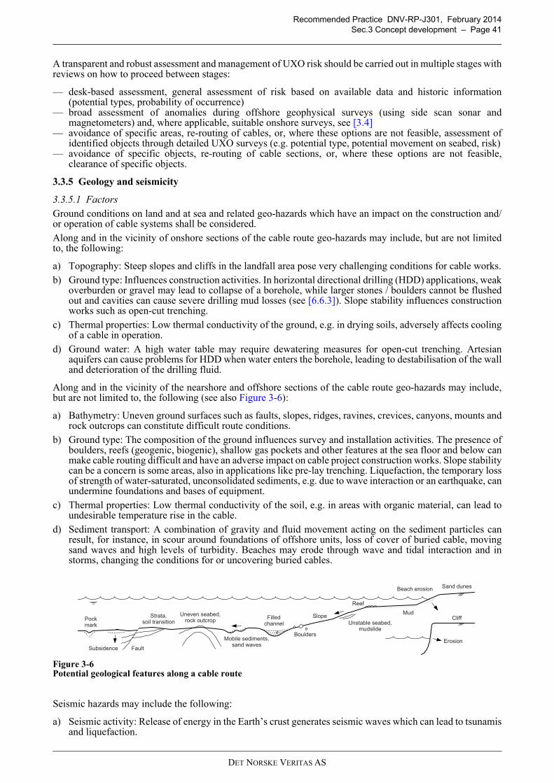
Recommended Practice DNV-RP-J301, February 2014
Sec.3 Concept development – Page 41
3.6
A transparent and robust assessment and management of UXO risk should be carried out in multiple stages withreviews on how to proceed between stages:
— desk-based assessment, general assessment of risk based on available data and historic information(potential types, probability of occurrence)
— broad assessment of anomalies during offshore geophysical surveys (using side scan sonar andmagnetometers) and, where applicable, suitable onshore surveys, see [3.4]
— avoidance of specific areas, re-routing of cables, or, where these options are not feasible, assessment ofidentified objects through detailed UXO surveys (e.g. potential type, potential movement on seabed, risk)
— avoidance of specific objects, re-routing of cable sections, or, where these options are not feasible,clearance of specific objects.
3.3.5 Geology and seismicity
3.3.5.1 Factors
Ground conditions on land and at sea and related geo-hazards which have an impact on the construction and/or operation of cable systems shall be considered.
Along and in the vicinity of onshore sections of the cable route geo-hazards may include, but are not limitedto, the following:
a) Topography: Steep slopes and cliffs in the landfall area pose very challenging conditions for cable works.
b) Ground type: Influences construction activities. In horizontal directional drilling (HDD) applications, weakoverburden or gravel may lead to collapse of a borehole, while larger stones / boulders cannot be flushedout and cavities can cause severe drilling mud losses (see [6.6.3]). Slope stability influences constructionworks such as open-cut trenching.
c) Thermal properties: Low thermal conductivity of the ground, e.g. in drying soils, adversely affects coolingof a cable in operation.
d) Ground water: A high water table may require dewatering measures for open-cut trenching. Artesianaquifers can cause problems for HDD when water enters the borehole, leading to destabilisation of the walland deterioration of the drilling fluid.
Along and in the vicinity of the nearshore and offshore sections of the cable route geo-hazards may include,but are not limited to, the following (see also Figure 3-6):
a) Bathymetry: Uneven ground surfaces such as faults, slopes, ridges, ravines, crevices, canyons, mounts androck outcrops can constitute difficult route conditions.
b) Ground type: The composition of the ground influences survey and installation activities. The presence ofboulders, reefs (geogenic, biogenic), shallow gas pockets and other features at the sea floor and below canmake cable routing difficult and have an adverse impact on cable project construction works. Slope stabilitycan be a concern is some areas, also in applications like pre-lay trenching. Liquefaction, the temporary lossof strength of water-saturated, unconsolidated sediments, e.g. due to wave interaction or an earthquake, canundermine foundations and bases of equipment.
c) Thermal properties: Low thermal conductivity of the soil, e.g. in areas with organic material, can lead toundesirable temperature rise in the cable.
d) Sediment transport: A combination of gravity and fluid movement acting on the sediment particles canresult, for instance, in scour around foundations of offshore units, loss of cover of buried cable, movingsand waves and high levels of turbidity. Beaches may erode through wave and tidal interaction and instorms, changing the conditions for or uncovering buried cables.
Figure 3-6Potential geological features along a cable route
Seismic hazards may include the following:
a) Seismic activity: Release of energy in the Earth’s crust generates seismic waves which can lead to tsunamisand liquefaction.
Sand dunesBeach erosion
MudSlope
Unstable seabed, mudslide
Boulders
Filled channel
Uneven seabed, rock outcrop
Fault
Pock mark
Strata,soil transition
Subsidence
Mobile sediments, sand waves
Reef
Cliff
Erosion
DET NORSKE VERITAS AS
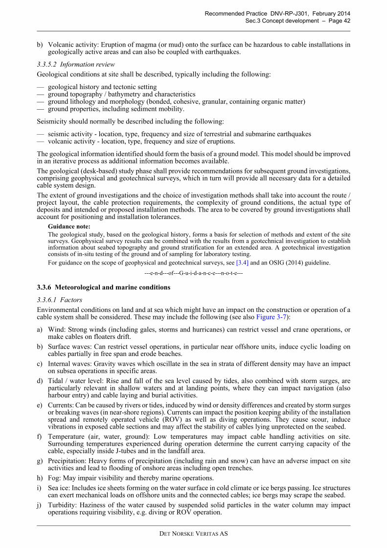
Recommended Practice DNV-RP-J301, February 2014
Sec.3 Concept development – Page 42
b) Volcanic activity: Eruption of magma (or mud) onto the surface can be hazardous to cable installations ingeologically active areas and can also be coupled with earthquakes.
3.3.5.2 Information review
Geological conditions at site shall be described, typically including the following:
— geological history and tectonic setting— ground topography / bathymetry and characteristics— ground lithology and morphology (bonded, cohesive, granular, containing organic matter)— ground properties, including sediment mobility.
Seismicity should normally be described including the following:
— seismic activity - location, type, frequency and size of terrestrial and submarine earthquakes— volcanic activity - location, type, frequency and size of eruptions.
The geological information identified should form the basis of a ground model. This model should be improvedin an iterative process as additional information becomes available.
The geological (desk-based) study phase shall provide recommendations for subsequent ground investigations,comprising geophysical and geotechnical surveys, which in turn will provide all necessary data for a detailedcable system design.
The extent of ground investigations and the choice of investigation methods shall take into account the route /project layout, the cable protection requirements, the complexity of ground conditions, the actual type ofdeposits and intended or proposed installation methods. The area to be covered by ground investigations shallaccount for positioning and installation tolerances.
Guidance note:
The geological study, based on the geological history, forms a basis for selection of methods and extent of the sitesurveys. Geophysical survey results can be combined with the results from a geotechnical investigation to establishinformation about seabed topography and ground stratification for an extended area. A geotechnical investigationconsists of in-situ testing of the ground and of sampling for laboratory testing.For guidance on the scope of geophysical and geotechnical surveys, see [3.4] and an OSIG (2014) guideline.
---e-n-d---of---G-u-i-d-a-n-c-e---n-o-t-e---
3.3.6 Meteorological and marine conditions
3.3.6.1 Factors
Environmental conditions on land and at sea which might have an impact on the construction or operation of acable system shall be considered. These may include the following (see also Figure 3-7):
a) Wind: Strong winds (including gales, storms and hurricanes) can restrict vessel and crane operations, ormake cables on floaters drift.
b) Surface waves: Can restrict vessel operations, in particular near offshore units, induce cyclic loading oncables partially in free span and erode beaches.
c) Internal waves: Gravity waves which oscillate in the sea in strata of different density may have an impacton subsea operations in specific areas.
d) Tidal / water level: Rise and fall of the sea level caused by tides, also combined with storm surges, areparticularly relevant in shallow waters and at landing points, where they can impact navigation (alsoharbour entry) and cable laying and burial activities.
e) Currents: Can be caused by rivers or tides, induced by wind or density differences and created by storm surgesor breaking waves (in near-shore regions). Currents can impact the position keeping ability of the installationspread and remotely operated vehicle (ROV) as well as diving operations. They cause scour, inducevibrations in exposed cable sections and may affect the stability of cables lying unprotected on the seabed.
f) Temperature (air, water, ground): Low temperatures may impact cable handling activities on site.Surrounding temperatures experienced during operation determine the current carrying capacity of thecable, especially inside J-tubes and in the landfall area.
g) Precipitation: Heavy forms of precipitation (including rain and snow) can have an adverse impact on siteactivities and lead to flooding of onshore areas including open trenches.
h) Fog: May impair visibility and thereby marine operations.
i) Sea ice: Includes ice sheets forming on the water surface in cold climate or ice bergs passing. Ice structurescan exert mechanical loads on offshore units and the connected cables; ice bergs may scrape the seabed.
j) Turbidity: Haziness of the water caused by suspended solid particles in the water column may impactoperations requiring visibility, e.g. diving or ROV operation.
DET NORSKE VERITAS AS
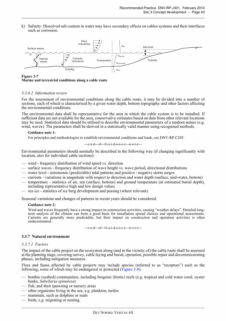
Recommended Practice DNV-RP-J301, February 2014
Sec.3 Concept development – Page 43
3.7
k) Salinity: Dissolved salt content in water may have secondary effects on cables systems and their interfacessuch as corrosion.
Figure 3-7Marine and terrestrial conditions along a cable route
3.3.6.2 Information review
For the assessment of environmental conditions along the cable route, it may be divided into a number ofsections, each of which is characterised by a given water depth, bottom topography and other factors affectingthe environmental conditions.
The environmental data shall be representative for the area in which the cable system is to be installed. Ifsufficient data are not available for the area, conservative estimates based on data from other relevant locationsmay be used. Statistical data should be utilised to describe environmental parameters of a random nature (e.g.wind, waves). The parameters shall be derived in a statistically valid manner using recognised methods.
Guidance note 1:
For principles and methodologies to establish environmental conditions and loads, see DNV-RP-C205.
---e-n-d---of---G-u-i-d-a-n-c-e---n-o-t-e---
Environmental parameters should normally be described in the following way (if changing significantly withlocation, also for individual cable sections):
— wind - frequency distribution of wind speed vs. direction— surface waves - frequency distribution of wave height vs. wave period, directional distributions— water level - astronomic (predictable) tidal patterns and positive / negative storm surges— currents - variations in magnitude with respect to direction and water depth (surface, mid-water, bottom)— temperature - statistics of air, sea (surface, bottom) and ground temperature (at estimated burial depth),
including representative high and low design values— sea ice - statistics of ice berg development and passing (where relevant).
Seasonal variations and changes of patterns in recent years should be considered.
Guidance note 2:
Wind and waves frequently have a strong impact on construction activities, causing “weather delays”. Detailed long-term analysis of the climate can form a good basis for installation spread choices and operational assessments.Currents are generally more predictable, but their impact on construction and operation activities is oftenunderestimated.
---e-n-d---of---G-u-i-d-a-n-c-e---n-o-t-e---
3.3.7 Natural environment
3.3.7.1 Factors
The impact of the cable project on the ecosystem along (and in the vicinity of) the cable route shall be assessedat the planning stage, covering survey, cable laying and burial, operation, possible repair and decommissioningphases, including mitigation measures.
Flora and fauna affected by cable projects may include species (referred to as “receptors”) such as thefollowing, some of which may be endangered or protected (Figure 3-8):
— benthic (seabed) communities, including biogenic (biotic) reefs (e.g. tropical and cold water coral, oysterbanks, Sabellaria spinulosa)
— fish, and their spawning or nursery areas— other organisms living in the sea, e.g. plankton, turtles— mammals, such as dolphins or seals— birds, e.g. migrating or nesting.
Surface waves
Internalwaves
Currents,turbulence
Wind,turbulence
Temperature
ϑair
ϑsea,top
ϑsea,bottom
ϑsoil
Sea level
Turbidity
Turbidity
DET NORSKE VERITAS AS
Recommended Practice DNV-RP-J301, February 2014
Sec.3 Concept development – Page 44
3.8
Figure 3-8Marine and terrestrial conditions along a cable route
Impacts on the environment encountered during cable system construction and operation can include:
a) Habitat loss: Degradation, fragmentation or destruction of habitat. Cable installation, in particular burial,may temporarily or permanently damage habitats offshore and in landfall areas.
b) Contamination: Presence or introduction of man-made chemicals and materials in the natural soilenvironment. If sediments in contaminated areas are disturbed during installation, contaminants may bemoved in suspension to nearby areas. The environmental impact of certain materials may be prohibitive.
c) Introduction of foreign materials: Deposition of new substrates into the natural environment, therebychanging the environmental characteristics. Cable protection such as rock placement can lead to reefforming and coastal processes can be modified in its immediate vicinity.
d) Turbidity: Suspension, dispersal and subsequent deposition of seabed sediments, dependent on ground typeand sediment grain. Cable burial activity can temporarily cause higher than natural levels of turbidity,leading to smothering of certain types of marine organisms.
e) Visual disturbance: During certain seasons, vessels and other temporary disturbances can distress birds andmammals.
f) Noise: Audible disturbance above background levels. Underwater noise during construction can distresscertain species of fish and mammals with high sensitivity hearing. Breeding birds in landfall areas may bedisturbed by onshore construction activities.Guidance note 1:
Noise levels during cable related works offshore are generally very low compared to, for instance, foundation pilingactivities in offshore wind farms.
---e-n-d---of---G-u-i-d-a-n-c-e---n-o-t-e---
g) Electromagnetic fields: In very close proximity, local or migratory fish that use the Earth’s electromagneticfields for navigation may be affected (avoidance, repulsion) by strong magnetic fields from cables.Guidance note 2:
The electrical field outside shielded power cables is zero. The strength of magnetic fields outside three-core AC cablesin operation is very low and mitigation measures are, from an environmental point of view, not required. Where singlecores of DC cables are laid in proximity, the external magnetic fields are minimised. Clear adverse effects of theremaining magnetic field on fish have not been demonstrated.
---e-n-d---of---G-u-i-d-a-n-c-e---n-o-t-e---
h) Heat transfer: Heating of habitat above natural levels. Heat losses from subsea cables can cause a changeof habitat conditions to local organisms.
Guidance note 3:
The environmental impact of a raised soil temperature in the direct vicinity of a subsea cable in operation due to cablelosses is currently not known with certainty. In an evaluation, the temperature rise should be considered in the contextof seabed / water temperature changes throughout the year, which can exceed 10 K in the North Sea.Countries may have specific requirements with regard to acceptable levels of thermal influence:
— Germany: Specific requirements exist with regard to the maximum value the seabed’s temperature may be raisedby the presence of a cable in operation. Bundesamt für Seeschifffahrt und Hydrographie (BSH) guidance “Designof offshore wind turbines” applies.
— United Kingdom: No specific requirements. If the Environmental Impact Assessment (see [3.3.7.2]) identifies anadverse impact, mitigation measures could be required.
---e-n-d---of---G-u-i-d-a-n-c-e---n-o-t-e---
Marine species can also directly or indirectly affect cable projects, in particular marine growth (fouling) onsubmerged structures, and should be assessed.
Cliff
Mammals
Fish
Tides
Dune
SaltmarshMud flat
Benthos
Feedingbirds
Breedingbirds
Reef
DET NORSKE VERITAS AS
Recommended Practice DNV-RP-J301, February 2014
Sec.3 Concept development – Page 45
3.3.7.2 Information review
High level information can generally be extracted from existing literature and databases, covering physical andsedimentary processes and seabed features. The following data are commonly collected:
— marine condition data to establish relationships between waves, tides and sediment mobility— bathymetric, geophysical survey and sediment composition data to ascertain the form of the seabed and
sedimentary quality / processes— water quality data— benthic community data— fish distribution data— ornithological data.
Considering conservation interests, an ‘envelope’ of envisioned activities and their potential impact should beestablished. Data should be investigated in a formal environmental impact assessment (EIA), leading to an‘environmental statement’ which details the nature and extent of potential (and allowable) impacts during eachphase of the lifecycle of the cable project.
Guidance note 1:
In areas with high turbidity potential, a presence of sensitive species and the envisioned use of burial techniques suchas chain cutting or jetting, a sediment plume study is advisable if the temporary turbidity increase is likely to besignificant compared to background levels.
---e-n-d---of---G-u-i-d-a-n-c-e---n-o-t-e---
When the EIA indicates that an unacceptable impact would be attained, possible mitigation measures shall beidentified, making use of practical experience within the industry.
Guidance note 2:
Care should be exercised that the environmental statement does not unnecessarily limit or exclude potential solutionsto project challenges.The mitigation measures identified in the EIA process are typically transposed into consent conditions orrequirements.Permit restriction may not only apply to an area but also to times when access for installation and repair activities isnot allowed (e.g. due to bird breeding; in Europe frequently between October and March). In such cases a route changeinvolving longer cable lengths may be advisable.
---e-n-d---of---G-u-i-d-a-n-c-e---n-o-t-e---
A potential mitigation measure is to avoid cable routing in designated conservation areas where possible.Guidance note 3:
Areas of conservation interest include, for instance, Marine Protected Areas, European Marine Sites, Special Areasof Conservation, Special Protection Areas, Sites of Special Scientific Interest, Ramsar sites and Marine ConservationZones.Further buffer zones around protected areas, e.g. 500 m wide, may constitute exclusion areas for cable works.
---e-n-d---of---G-u-i-d-a-n-c-e---n-o-t-e---
Where avoidance of sensitive areas is not an option, monitoring and mitigation measures for the relevantproject phase should be identified, e.g.:
— pre- and post-construction monitoring— method and/or timing restrictions for survey activities, installation works or repairs— re-instatement of site to pre-construction condition— other environmental compensation works.
3.4 Cable route survey
3.4.1 General
Detailed data shall be obtained for the total length of the planned cable route, covering a corridor of sufficientwidth to provide adequate information for design of the cable route as well as installation and operation relatedactivities, taking into account possible route adjustments due to subsequent findings.
Guidance note 1:
Surveys in nearshore, intertidal and mud flat areas may be more difficult to conduct than in onshore or offshore areas.Minimum requirements to cover these areas adequately should be established.
---e-n-d---of---G-u-i-d-a-n-c-e---n-o-t-e---
Data for the onshore part of a cable route can frequently be obtained from official sources. Data for the offshorepart of a cable route should normally be obtained from national hydrographic institutions, supported by resultsfrom dedicated surveys.
DET NORSKE VERITAS AS

Recommended Practice DNV-RP-J301, February 2014
Sec.3 Concept development – Page 46
Guidance note 2:
Data on planned activities may be obtainable from trade organisations and market intelligence services.
---e-n-d---of---G-u-i-d-a-n-c-e---n-o-t-e---
All survey data shall be geo-referenced to allow overlaying of subsequently obtained data, e.g. in a geographicalinformation system.
3.4.2 Onshore surveys
Where the cable project includes shore landings or an onshore section, a site visit should normally examine:
— marine and terrestrial constraints like infrastructure, features, utilities and conflicting developments /activities along the prospective cable route and at the beach
— beach utilisation, e.g. for tourism— harbour / nearshore activities, e.g. fishing and marine traffic— local ground conditions along the cable route and at the beach, including the need for setting up hard
standing for machinery or temporary storage— during any excavation work, consideration of archaeologically or culturally significant findings— site accessibility, e.g. for road transportation and available storage / working space— local facilities for construction and operations periods, including communication, transportation, fresh
water, services— potential for community involvement.
Onshore ground conditions may be available from local or national authorities. Where such information cannotbe obtained, onshore ground investigations should be conducted to a level adequate for the project. Groundinvestigations should normally comprise the following types of investigation:
— site geological study (see [3.3.5])— geotechnical investigations, e.g. standard penetration test (SPT) in weak rock, cone penetration tests (CPT)
in soil— borehole drilling with representative soil sampling and subsequent laboratory testing— identification of ground contamination.
Guidance note:
Thermal conductivity of the ground is a significant design parameter which should be established through in-situtesting and/or laboratory analysis.For HDD applications, penetration tests and borings should be made at entry and exit points. Depending on thegeological conditions, penetration tests are typically made at least every 100 to 200 m along the route with additionalinvestigation borings for every second penetration location. In order to avoid break-outs during horizontal drilling,borings should be offset horizontally from the planned HDD centre line. For all geotechnical tests, penetrations downto anticipated HDD trajectory plus at least 5 m should be achieved.
---e-n-d---of---G-u-i-d-a-n-c-e---n-o-t-e---
Meetings with relevant local organisations such as fishermen’s representatives or environmental interestgroups can be helpful in establishing a dialogue.
3.4.3 Offshore surveys
Ground investigations offshore should normally comprise the following types of investigation:
— site geological study (see [3.3.5])— geophysical investigations of the bathymetry of the seabed using multi-beam echo-sounder, of the sea floor
texture using side scan sonar and of objects on the seabed using side scan sonar and magnetometer— geophysical investigation of the shallow geology using sub-bottom profiling— geotechnical investigations, e.g. CPT— soil sampling, e.g. by vibrocoring or grab-sampling, with subsequent laboratory testing for ground truthing— specialist surveys, e.g. satellite imaging to collect information on the morpho-dynamics of an area, UXO
surveys.
Guidance note 1:
The extent and content of a ground investigation programme are no straight-forward issues and will depend on thespecifics of the cable project. An experienced geotechnical engineer who is familiar with cables and their installationand who represents the developer or owner should be present during the ground investigation surveys. Depending onthe findings during the investigations, actions may be taken to adjust the ground investigation programme during itsexecution. This may include suggestions for increased depths of planned tests, suggestions for additional tests, andsuggestions for changed positions of investigations and tests.When non-homogeneous soil deposits are encountered or when difficult ground conditions are identified locally, itmay be necessary to carry out more tests than the tentative minimum recommended below.
DET NORSKE VERITAS AS
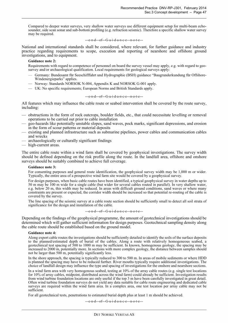
Recommended Practice DNV-RP-J301, February 2014
Sec.3 Concept development – Page 47
Compared to deeper water surveys, very shallow water surveys use different equipment setup for multi-beam echo-sounder, side scan sonar and sub-bottom profiling (e.g. refraction seismic). Therefore a specific shallow water surveymay be required.
---e-n-d---of---G-u-i-d-a-n-c-e---n-o-t-e---
National and international standards shall be considered, where relevant, for further guidance and industrypractice regarding requirements to scope, execution and reporting of nearshore and offshore groundinvestigations, and to equipment.
Guidance note 2:
Requirements with regard to competence of personnel on board the survey vessel may apply, e.g. with regard to geo-survey and/or archaeological qualification. Local requirements for geological surveys apply:
— Germany: Bundesamt für Seeschifffahrt und Hydrographie (BSH) guidance “Baugrunderkundung für Offshore-Windenergieparks” applies.
— Norway: Standards NORSOK N-004, Appendix K and NORSOK G-001 apply.— UK: No specific requirements; European Norms and British Standards apply.
---e-n-d---of---G-u-i-d-a-n-c-e---n-o-t-e---
All features which may influence the cable route or seabed intervention shall be covered by the route survey,including:
— obstructions in the form of rock outcrops, boulder fields, etc., that could necessitate levelling or removaloperations to be carried out prior to cable installation
— geo-hazards like potentially unstable slopes, sand waves, pock marks, significant depressions, and erosionin the form of scour patterns or material deposits
— existing and planned infrastructure such as submarine pipelines, power cables and communication cablesand wrecks
— archaeologically or culturally significant findings— high-current areas.
The entire cable route within a wind farm shall be covered by geophysical investigations. The survey widthshould be defined depending on the risk profile along the route. In the landfall area, offshore and onshoresurveys should be suitably combined to achieve full coverage.
Guidance note 3:
For consenting purposes and general route identification, the geophysical survey width may be 1,000 m or wider.Typically, the entire area of a prospective wind farm site would be covered by a geophysical survey.For design purposes, when basic cable routes have been identified, a typical geophysical survey in water depths up to50 m may be 100 m wide for a single cable (but wider for several cables routed in parallel). In very shallow water,e.g. below 20 m, this width may be reduced. In areas with difficult ground conditions, sand waves or where manyconstraints are present or expected, the corridor width should be increased so that potential re-routing of the cable iscovered by the survey.The line spacing of the seismic survey at a cable route section should be sufficiently small to detect all soil strata ofsignificance for the design and installation of the cable.
---e-n-d---of---G-u-i-d-a-n-c-e---n-o-t-e---
Depending on the findings of the geophysical programme, the amount of geotechnical investigations should bedetermined which will gather sufficient information for design purposes. Geotechnical sampling density alongthe cable route should be established based on the ground model.
Guidance note 4:
Along export cable routes the investigations should be sufficiently detailed to identify the soils of the surface depositsto the planned/estimated depth of burial of the cables. Along a route with relatively homogeneous seabed, ageotechnical test spacing of 500 to 1000 m may be sufficient. In known, homogenous geology, the spacing may beincreased to 2000 m, potentially more. In sections with more complex geology, the distance between samples shouldnot be larger than 500 m, potentially significantly less.In the shore approach, the spacing is typically reduced to 300 to 500 m. In areas of mobile sediments or where HDDis planned the spacing may have to be reduced further. River mouths typically require additional investigations. Thechoice of landfall design may influence the type and spacing of investigations for the onshore and nearshore sections.In a wind farm area with very homogenous seabed, testing at 10% of the array cable routes (e.g. single test locationsfor 10% of array cables, midpoint, distributed across the wind farm) could already be sufficient. Investigation resultsfrom wind turbine foundation locations are only useful if the top 3 m have been carefully investigated in great detail.Often wind turbine foundation surveys do not yield any data suitable for cable route engineering and dedicated cablesurveys are required within the wind farm area. In a complex area, one test location per array cable may not besufficient.For all geotechnical tests, penetrations to estimated burial depth plus at least 1 m should be achieved.
---e-n-d---of---G-u-i-d-a-n-c-e---n-o-t-e---
DET NORSKE VERITAS AS
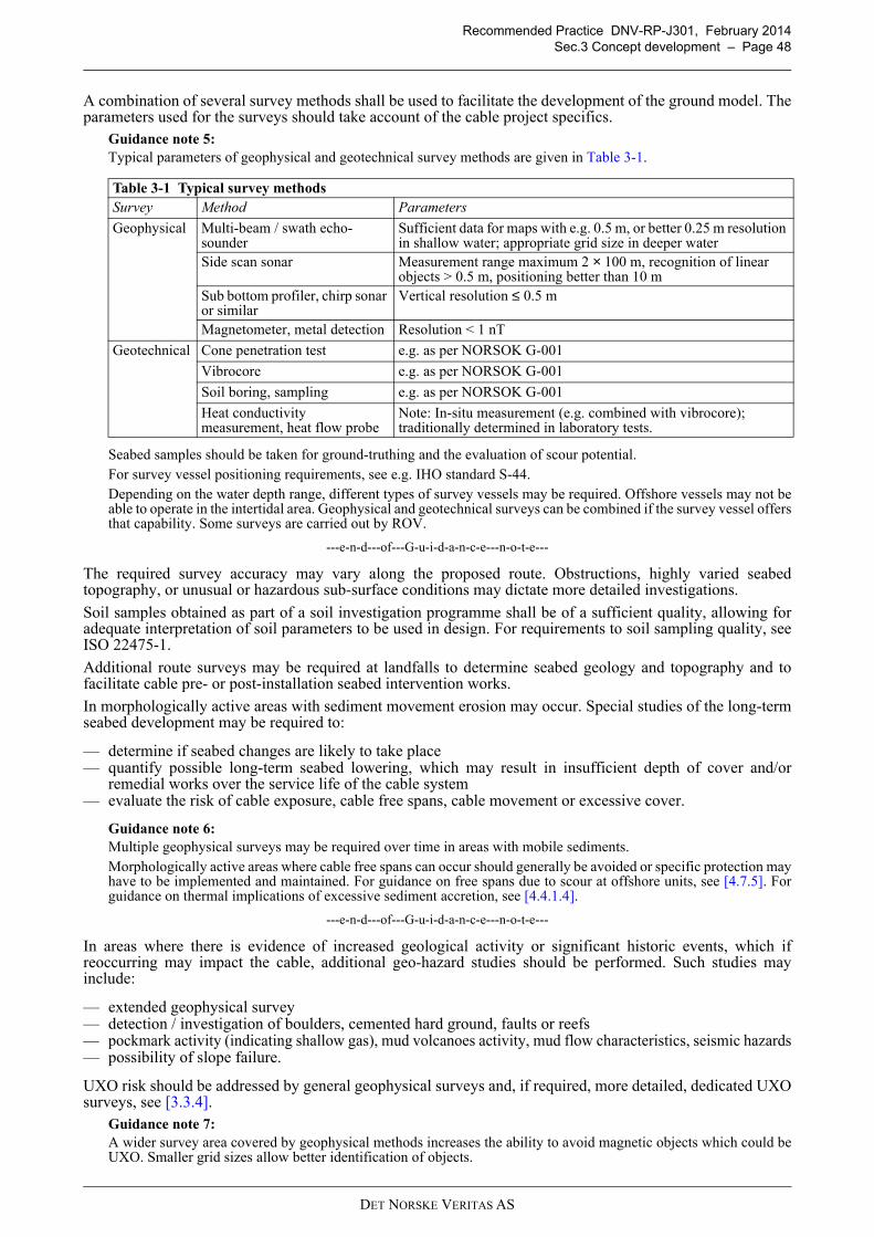
Recommended Practice DNV-RP-J301, February 2014
Sec.3 Concept development – Page 48
A combination of several survey methods shall be used to facilitate the development of the ground model. Theparameters used for the surveys should take account of the cable project specifics.
Guidance note 5:
Typical parameters of geophysical and geotechnical survey methods are given in Table 3-1.
Seabed samples should be taken for ground-truthing and the evaluation of scour potential.For survey vessel positioning requirements, see e.g. IHO standard S-44.Depending on the water depth range, different types of survey vessels may be required. Offshore vessels may not beable to operate in the intertidal area. Geophysical and geotechnical surveys can be combined if the survey vessel offersthat capability. Some surveys are carried out by ROV.
---e-n-d---of---G-u-i-d-a-n-c-e---n-o-t-e---
The required survey accuracy may vary along the proposed route. Obstructions, highly varied seabedtopography, or unusual or hazardous sub-surface conditions may dictate more detailed investigations.
Soil samples obtained as part of a soil investigation programme shall be of a sufficient quality, allowing foradequate interpretation of soil parameters to be used in design. For requirements to soil sampling quality, seeISO 22475-1.
Additional route surveys may be required at landfalls to determine seabed geology and topography and tofacilitate cable pre- or post-installation seabed intervention works.
In morphologically active areas with sediment movement erosion may occur. Special studies of the long-termseabed development may be required to:
— determine if seabed changes are likely to take place— quantify possible long-term seabed lowering, which may result in insufficient depth of cover and/or
remedial works over the service life of the cable system— evaluate the risk of cable exposure, cable free spans, cable movement or excessive cover.
Guidance note 6:
Multiple geophysical surveys may be required over time in areas with mobile sediments.Morphologically active areas where cable free spans can occur should generally be avoided or specific protection mayhave to be implemented and maintained. For guidance on free spans due to scour at offshore units, see [4.7.5]. Forguidance on thermal implications of excessive sediment accretion, see [4.4.1.4].
---e-n-d---of---G-u-i-d-a-n-c-e---n-o-t-e---
In areas where there is evidence of increased geological activity or significant historic events, which ifreoccurring may impact the cable, additional geo-hazard studies should be performed. Such studies mayinclude:
— extended geophysical survey— detection / investigation of boulders, cemented hard ground, faults or reefs— pockmark activity (indicating shallow gas), mud volcanoes activity, mud flow characteristics, seismic hazards— possibility of slope failure.
UXO risk should be addressed by general geophysical surveys and, if required, more detailed, dedicated UXOsurveys, see [3.3.4].
Guidance note 7:
A wider survey area covered by geophysical methods increases the ability to avoid magnetic objects which could beUXO. Smaller grid sizes allow better identification of objects.
Table 3-1 Typical survey methods
Survey Method Parameters
Geophysical Multi-beam / swath echo-sounder
Sufficient data for maps with e.g. 0.5 m, or better 0.25 m resolution in shallow water; appropriate grid size in deeper water
Side scan sonar Measurement range maximum 2 × 100 m, recognition of linear objects > 0.5 m, positioning better than 10 m
Sub bottom profiler, chirp sonar or similar
Vertical resolution ≤ 0.5 m
Magnetometer, metal detection Resolution < 1 nT
Geotechnical Cone penetration test e.g. as per NORSOK G-001
Vibrocore e.g. as per NORSOK G-001
Soil boring, sampling e.g. as per NORSOK G-001
Heat conductivity measurement, heat flow probe
Note: In-situ measurement (e.g. combined with vibrocore); traditionally determined in laboratory tests.
DET NORSKE VERITAS AS
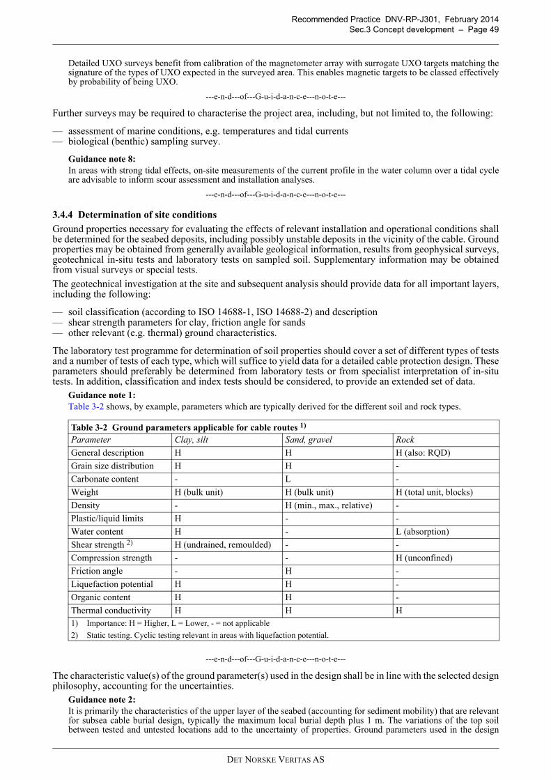
Recommended Practice DNV-RP-J301, February 2014
Sec.3 Concept development – Page 49
Detailed UXO surveys benefit from calibration of the magnetometer array with surrogate UXO targets matching thesignature of the types of UXO expected in the surveyed area. This enables magnetic targets to be classed effectivelyby probability of being UXO.
---e-n-d---of---G-u-i-d-a-n-c-e---n-o-t-e---
Further surveys may be required to characterise the project area, including, but not limited to, the following:
— assessment of marine conditions, e.g. temperatures and tidal currents— biological (benthic) sampling survey.
Guidance note 8:
In areas with strong tidal effects, on-site measurements of the current profile in the water column over a tidal cycleare advisable to inform scour assessment and installation analyses.
---e-n-d---of---G-u-i-d-a-n-c-e---n-o-t-e---
3.4.4 Determination of site conditions
Ground properties necessary for evaluating the effects of relevant installation and operational conditions shallbe determined for the seabed deposits, including possibly unstable deposits in the vicinity of the cable. Groundproperties may be obtained from generally available geological information, results from geophysical surveys,geotechnical in-situ tests and laboratory tests on sampled soil. Supplementary information may be obtainedfrom visual surveys or special tests.
The geotechnical investigation at the site and subsequent analysis should provide data for all important layers,including the following:
— soil classification (according to ISO 14688-1, ISO 14688-2) and description— shear strength parameters for clay, friction angle for sands— other relevant (e.g. thermal) ground characteristics.
The laboratory test programme for determination of soil properties should cover a set of different types of testsand a number of tests of each type, which will suffice to yield data for a detailed cable protection design. Theseparameters should preferably be determined from laboratory tests or from specialist interpretation of in-situtests. In addition, classification and index tests should be considered, to provide an extended set of data.
Guidance note 1:
Table 3-2 shows, by example, parameters which are typically derived for the different soil and rock types.
---e-n-d---of---G-u-i-d-a-n-c-e---n-o-t-e---
The characteristic value(s) of the ground parameter(s) used in the design shall be in line with the selected designphilosophy, accounting for the uncertainties.
Guidance note 2:
It is primarily the characteristics of the upper layer of the seabed (accounting for sediment mobility) that are relevantfor subsea cable burial design, typically the maximum local burial depth plus 1 m. The variations of the top soilbetween tested and untested locations add to the uncertainty of properties. Ground parameters used in the design
Table 3-2 Ground parameters applicable for cable routes 1)
Parameter Clay, silt Sand, gravel Rock
General description H H H (also: RQD)
Grain size distribution H H -
Carbonate content - L -
Weight H (bulk unit) H (bulk unit) H (total unit, blocks)
Density - H (min., max., relative) -
Plastic/liquid limits H - -
Water content H - L (absorption)
Shear strength 2) H (undrained, remoulded) - -
Compression strength - - H (unconfined)
Friction angle - H -
Liquefaction potential H H -
Organic content H H -
Thermal conductivity H H H1) Importance: H = Higher, L = Lower, - = not applicable
2) Static testing. Cyclic testing relevant in areas with liquefaction potential.
DET NORSKE VERITAS AS
Recommended Practice DNV-RP-J301, February 2014
Sec.3 Concept development – Page 50
should therefore be defined with upper bound, best estimate and lower bound limits valid within defined areas orsections of the route.Since the distance between ground investigation locations can be large, the assumed ground characteristics in a designsituation at a specific point of the route should be the unfavourable of high and low estimates. For determination ofthe characteristic value of a soil property from limited data, see DNV-RP-C207.Raw ground survey data may also be provided to cable installers, preferably in GIS format, for additional burialassessment and/or burial tool capability assessment.
---e-n-d---of---G-u-i-d-a-n-c-e---n-o-t-e---
Additional investigation of the seabed material may be required to evaluate specific scenarios, as for example:
— challenges with respect to excavation and burial operations in areas with inhomogeneous ground conditions— unstable subsurface when crossing post-glacial features like eskers or moraines— possibility of mud slides or liquefaction as a result of cyclic loading, caused by waves— challenges with respect to cable crossing— probability of forming free spans caused by megaripples / sand waves or scouring during the operational
phase— high organic material content (e.g. peat) impacting trenching or heat transfer— planned beaching of vessel or work in energetic inter-tidal areas.
Guidance note 3:
Detailed investigations may include trialling of burial equipment and techniques without cable or with a dummy,thereby effectively de-risking future cable burial.
---e-n-d---of---G-u-i-d-a-n-c-e---n-o-t-e---
The geological report should, as a minimum, contain the following information:
— brief project description— terms of reference, reporting standards— description of planned and executed investigation(s) including specifications / limitations of the survey tool
used in the works— results of the individual investigations— combination and visualisation of results from geological study, geophysical survey, geotechnical survey
and laboratory testing— description of anomalies— interpretation of the results.
DET NORSKE VERITAS AS
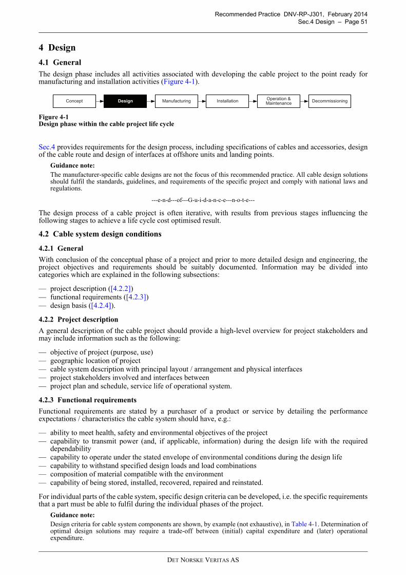
Recommended Practice DNV-RP-J301, February 2014
Sec.4 Design – Page 51
4 Design
4.1 General
The design phase includes all activities associated with developing the cable project to the point ready formanufacturing and installation activities (Figure 4-1).
Figure 4-1Design phase within the cable project life cycle
Sec.4 provides requirements for the design process, including specifications of cables and accessories, designof the cable route and design of interfaces at offshore units and landing points.
Guidance note:
The manufacturer-specific cable designs are not the focus of this recommended practice. All cable design solutionsshould fulfil the standards, guidelines, and requirements of the specific project and comply with national laws andregulations.
---e-n-d---of---G-u-i-d-a-n-c-e---n-o-t-e---
The design process of a cable project is often iterative, with results from previous stages influencing thefollowing stages to achieve a life cycle cost optimised result.
4.2 Cable system design conditions
4.2.1 General
With conclusion of the conceptual phase of a project and prior to more detailed design and engineering, theproject objectives and requirements should be suitably documented. Information may be divided intocategories which are explained in the following subsections:
— project description ([4.2.2])— functional requirements ([4.2.3])— design basis ([4.2.4]).
4.2.2 Project description
A general description of the cable project should provide a high-level overview for project stakeholders andmay include information such as the following:
— objective of project (purpose, use)— geographic location of project— cable system description with principal layout / arrangement and physical interfaces— project stakeholders involved and interfaces between— project plan and schedule, service life of operational system.
4.2.3 Functional requirements
Functional requirements are stated by a purchaser of a product or service by detailing the performanceexpectations / characteristics the cable system should have, e.g.:
— ability to meet health, safety and environmental objectives of the project— capability to transmit power (and, if applicable, information) during the design life with the required
dependability— capability to operate under the stated envelope of environmental conditions during the design life— capability to withstand specified design loads and load combinations— composition of material compatible with the environment— capability of being stored, installed, recovered, repaired and reinstated.
For individual parts of the cable system, specific design criteria can be developed, i.e. the specific requirementsthat a part must be able to fulfil during the individual phases of the project.
Guidance note:
Design criteria for cable system components are shown, by example (not exhaustive), in Table 4-1. Determination ofoptimal design solutions may require a trade-off between (initial) capital expenditure and (later) operationalexpenditure.
DesignConceptOperation & Maintenance
Installation DecommissioningManufacturing
DET NORSKE VERITAS AS
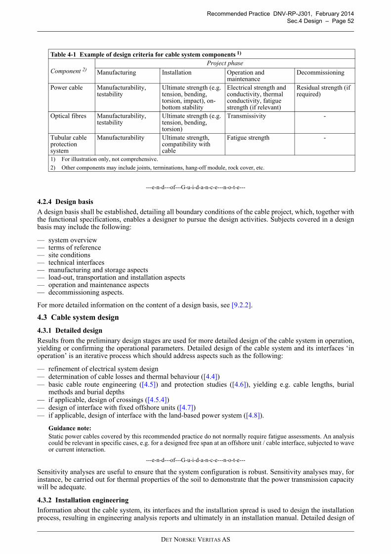
Recommended Practice DNV-RP-J301, February 2014
Sec.4 Design – Page 52
---e-n-d---of---G-u-i-d-a-n-c-e---n-o-t-e---
4.2.4 Design basis
A design basis shall be established, detailing all boundary conditions of the cable project, which, together withthe functional specifications, enables a designer to pursue the design activities. Subjects covered in a designbasis may include the following:
— system overview— terms of reference— site conditions— technical interfaces— manufacturing and storage aspects— load-out, transportation and installation aspects— operation and maintenance aspects— decommissioning aspects.
For more detailed information on the content of a design basis, see [9.2.2].
4.3 Cable system design
4.3.1 Detailed design
Results from the preliminary design stages are used for more detailed design of the cable system in operation,yielding or confirming the operational parameters. Detailed design of the cable system and its interfaces ‘inoperation’ is an iterative process which should address aspects such as the following:
— refinement of electrical system design— determination of cable losses and thermal behaviour ([4.4])— basic cable route engineering ([4.5]) and protection studies ([4.6]), yielding e.g. cable lengths, burial
methods and burial depths— if applicable, design of crossings ([4.5.4])— design of interface with fixed offshore units ([4.7])— if applicable, design of interface with the land-based power system ([4.8]).
Guidance note:
Static power cables covered by this recommended practice do not normally require fatigue assessments. An analysiscould be relevant in specific cases, e.g. for a designed free span at an offshore unit / cable interface, subjected to waveor current interaction.
---e-n-d---of---G-u-i-d-a-n-c-e---n-o-t-e---
Sensitivity analyses are useful to ensure that the system configuration is robust. Sensitivity analyses may, forinstance, be carried out for thermal properties of the soil to demonstrate that the power transmission capacitywill be adequate.
4.3.2 Installation engineering
Information about the cable system, its interfaces and the installation spread is used to design the installationprocess, resulting in engineering analysis reports and ultimately in an installation manual. Detailed design of
Table 4-1 Example of design criteria for cable system components 1)
Component 2)
Project phase
Manufacturing Installation Operation and maintenance
Decommissioning
Power cable Manufacturability, testability
Ultimate strength (e.g. tension, bending, torsion, impact), on-bottom stability
Electrical strength and conductivity, thermal conductivity, fatigue strength (if relevant)
Residual strength (if required)
Optical fibres Manufacturability, testability
Ultimate strength (e.g. tension, bending, torsion)
Transmissivity -
Tubular cable protection system
Manufacturability Ultimate strength, compatibility with cable
Fatigue strength -
1) For illustration only, not comprehensive.
2) Other components may include joints, terminations, hang-off module, rock cover, etc.
DET NORSKE VERITAS AS
Recommended Practice DNV-RP-J301, February 2014
Sec.4 Design – Page 53
the installation steps for cable system and its interfaces is an iterative process which should address scenarios,including contingencies and repairs, such as the following:
— cable storage, load-out and transport (see also Sec.5)— cable laying, e.g. offshore, in landfall area and/or at infrastructure crossings (see also Sec.6)— cable pull-in at offshore units and landfall (see also Sec.6)— cable burial, including burial tools and their characteristics (see also Sec.6)— cable protection by non-burial methods (see also Sec.6).
All phases of the cable installation operation shall be designed and analysed according to the principles statedin the applicable rules for marine operations and for the chosen operational limiting conditions, see [6.1]. Theinstallation design shall demonstrate that the power cable system can be installed safely using the intendedvessel and installation equipment and within the allowable limits, i.e. with acceptable risks to product andequipment.
The installation design shall provide an acceptable operations envelope used during the actual installationprocess in order to facilitate control over the cable configuration at all times. This may include, for instance:
— confirmation of cable system mechanical properties including, for instance, submerged weight, tensilestrength, minimum bending radius
— definition of the operational limiting criteria with selected installation spread— determination of laying parameters (e.g. minimum lay angle, maximum lay tension, minimum layback) to
be maintained along the cable route— detailed cable route engineering (including at offshore units, lay tolerances)— verification of cable capacity in combined tension and bending and with respect to radial compression from
cable engine tracks and chute contact.
Guidance note 1:
Static and dynamic installation analyses should ensure that the cable’s mechanical properties are adequate for theplanned process. The analyses should provide the control parameters for managing the catenary during the layingprocess and pull-in, both for typical and worst-case scenarios.
---e-n-d---of---G-u-i-d-a-n-c-e---n-o-t-e---
The outcome of installation analyses should be reflected in the installation manual, specifications anddrawings.
Guidance note 2:
The loading capabilities of the cable installation vessel and the operational limiting criteria will also determine themaximum cable length that can be installed and the number of joints required in long cables.
---e-n-d---of---G-u-i-d-a-n-c-e---n-o-t-e---
In a burial assessment study the ground conditions along the cable route should be assessed and the final burialdesign determined ([4.6.3]). A tool capability assessment should determine the equipment most suitable for theoperation and yield estimates for performance ([6.7.2]).
The extent of, and the requirements for, seabed preparation shall be determined and specified, taking intoaccount laying tolerances and the potential for route changes. Required activities may comprise routeclearance, pre-lay grapnel runs and pre-lay trenching ([6.5.2]).
4.4 Cable system
4.4.1 Power cables
4.4.1.1 General
Manufacturer and purchaser shall agree on the requirements for the cable design with regard to performance,testing, storage, load-out, transport, installation, operation, maintenance, repair and decommissioning. Thesemay include the items listed in the following subsections.
Guidance note:
For preliminary cable selection, see [3.2.4]. For further guidance applicable to AC cables, see App.B. Taking thecharacteristics of DC transmission into account, the guidance provided in App.B may also aid the specification of DCcables.
---e-n-d---of---G-u-i-d-a-n-c-e---n-o-t-e---
4.4.1.2 Project information
The purchaser should provide general project information to the manufacturer such as the following. Forfurther details see [B.2]:
a) Project data: Name, location, water depth.
DET NORSKE VERITAS AS
Recommended Practice DNV-RP-J301, February 2014
Sec.4 Design – Page 54
b) Project layout: Key information on cable interface points (e.g. at wind turbines, offshore substations,onshore grid connection).
c) Route length: Cable type, preliminary or final route length(s).
d) Cable system life: Design life (e.g. ≥ 25 years) and planned service life (e.g. 20 years).
Guidance note:
Cables “age” predominantly through deterioration of the insulation material under influence of electric stress,mechanical stress, temperature and chemical aggression (including humidity and UV irradiation). Well protectedsubsea power cables can achieve a service life of 30 to 40 years.
---e-n-d---of---G-u-i-d-a-n-c-e---n-o-t-e---
4.4.1.3 Electrical specifications
Voltage, frequency, short circuit ratings and the current / power carrying capacity (or the conductor cross-section, see [4.4.1.6]) should be provided by the purchaser. Reference should be made to the relevant IECpublication. With a finalised design, the manufacturer is able to provide cable parameters suitable for powerflow simulations. For further details see [B.3].
a) System voltages: Nominal and maximum voltages used; lightning overvoltage / impulse withstand voltagelevels required.
Guidance note:
AC system design voltages should be specified according to IEC 60183 in the format U0 / U (Um), where U0 is therated rms power-frequency voltage between each conductor and screen (or sheath), U is the rms power-frequencyvoltage between any two conductors and Um is the maximum power-frequency voltage between any two conductors(i.e. the highest voltage that can be sustained under normal operating conditions). Example specifications for cablesused in offshore wind farms are as follows:
— 18 / 33 (36) kV - typical array cable voltage
— 36 / 66 (72.5) kV - potential array cable voltage for large wind farms with > 5 MW turbines
— 76 / 132 (145) kV - typical export cable voltage in the United Kingdom
— 127 / 220 (245) kV - potential export cable voltage for large wind farms.
---e-n-d---of---G-u-i-d-a-n-c-e---n-o-t-e---
b) System frequency: Nominal frequency, i.e. 50 Hz or 60 Hz.
c) Capacity: Rated current (or power) for continuous operation. Where known, specific current load profilesmay also be used to determine cyclic or dynamic rating.
d) Short-circuit withstand capability: Maximum current and duration for symmetrical 3-phase short circuitfaults and asymmetrical phase-to-earth short circuit faults.
e) Earthing: Concept of screen/sheath earthing.
f) Electrical properties: Parameters of equivalent electrical circuit (DC and AC resistance; positive, negativeand zero sequence impedances) and losses (by contributing cable element).
4.4.1.4 Thermal specifications
Current losses from conductors and metallic covers as well as dielectric losses in the insulation are transferredthrough the cable surface to the environment, e.g. soil, water or air. In steady state conditions, the temperaturedifference between conductor (limited by the maximum temperature of the insulating material) and ambientdepends on the total loss per metre cable and the total thermal resistance.
The current-carrying capacity of the cable is largely determined by the thermal properties of its surroundings.Applicable cases should be assessed, e.g. cable in J- or I-tube (Figure 4-2 a), cable buried in the seabed (Figure4-2 b) and/or cable inside conduit (Figure 4-2 c).
Guidance note:
Direct application of ‘steady-state’ IEC standards to ‘dynamic’ offshore wind applications can lead to veryconservative cable cross-section choices when assuming steady state conditions at nominal power output. In theseabed it normally takes many days before steady-state conditions are reached; in a J-tube it normally only takes afew hours.
Typical hot spots can be found where the cable leaves the water, e.g. inside a J-tube or above the water table withinthe landfall area.
---e-n-d---of---G-u-i-d-a-n-c-e---n-o-t-e---
DET NORSKE VERITAS AS
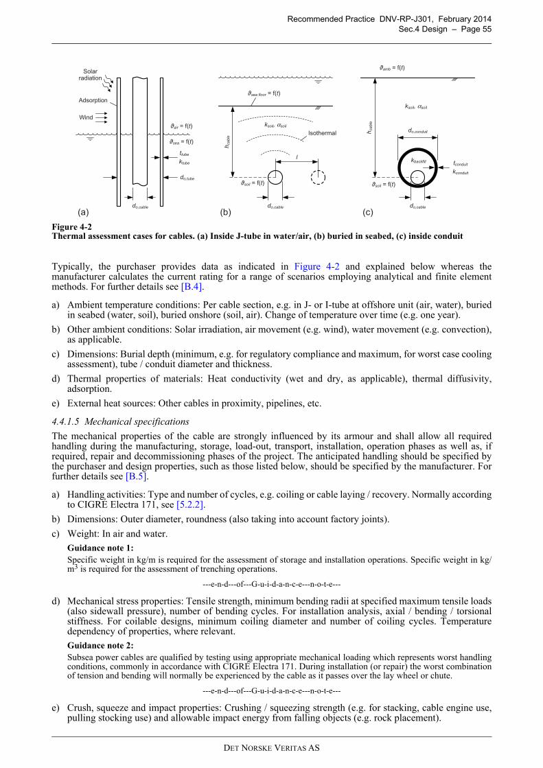
Recommended Practice DNV-RP-J301, February 2014
Sec.4 Design – Page 55
Figure 4-2Thermal assessment cases for cables. (a) Inside J-tube in water/air, (b) buried in seabed, (c) inside conduit
Typically, the purchaser provides data as indicated in Figure 4-2 and explained below whereas themanufacturer calculates the current rating for a range of scenarios employing analytical and finite elementmethods. For further details see [B.4].
a) Ambient temperature conditions: Per cable section, e.g. in J- or I-tube at offshore unit (air, water), buriedin seabed (water, soil), buried onshore (soil, air). Change of temperature over time (e.g. one year).
b) Other ambient conditions: Solar irradiation, air movement (e.g. wind), water movement (e.g. convection),as applicable.
c) Dimensions: Burial depth (minimum, e.g. for regulatory compliance and maximum, for worst case coolingassessment), tube / conduit diameter and thickness.
d) Thermal properties of materials: Heat conductivity (wet and dry, as applicable), thermal diffusivity,adsorption.
e) External heat sources: Other cables in proximity, pipelines, etc.
4.4.1.5 Mechanical specifications
The mechanical properties of the cable are strongly influenced by its armour and shall allow all requiredhandling during the manufacturing, storage, load-out, transport, installation, operation phases as well as, ifrequired, repair and decommissioning phases of the project. The anticipated handling should be specified bythe purchaser and design properties, such as those listed below, should be specified by the manufacturer. Forfurther details see [B.5].
a) Handling activities: Type and number of cycles, e.g. coiling or cable laying / recovery. Normally accordingto CIGRÉ Electra 171, see [5.2.2].
b) Dimensions: Outer diameter, roundness (also taking into account factory joints).
c) Weight: In air and water.
Guidance note 1:
Specific weight in kg/m is required for the assessment of storage and installation operations. Specific weight in kg/m3 is required for the assessment of trenching operations.
---e-n-d---of---G-u-i-d-a-n-c-e---n-o-t-e---
d) Mechanical stress properties: Tensile strength, minimum bending radii at specified maximum tensile loads(also sidewall pressure), number of bending cycles. For installation analysis, axial / bending / torsionalstiffness. For coilable designs, minimum coiling diameter and number of coiling cycles. Temperaturedependency of properties, where relevant.
Guidance note 2:
Subsea power cables are qualified by testing using appropriate mechanical loading which represents worst handlingconditions, commonly in accordance with CIGRÉ Electra 171. During installation (or repair) the worst combinationof tension and bending will normally be experienced by the cable as it passes over the lay wheel or chute.
---e-n-d---of---G-u-i-d-a-n-c-e---n-o-t-e---
e) Crush, squeeze and impact properties: Crushing / squeezing strength (e.g. for stacking, cable engine use,pulling stocking use) and allowable impact energy from falling objects (e.g. rock placement).
do,cable
(c)(b)(a)
hca
ble
do,cable
do,conduit
tconduitkbackfill
ksoil, αsoil
amb = f(t)
kconduit
soil = f(t)
hca
ble
sea floor = f(t)
soil = f(t)
ksoil, αsoil
do,cable
l
Isothermal
ttube
do,tube
sea = f(t)
air = f(t)
Wind
Solarradiation
Adsorption
ktube
DET NORSKE VERITAS AS
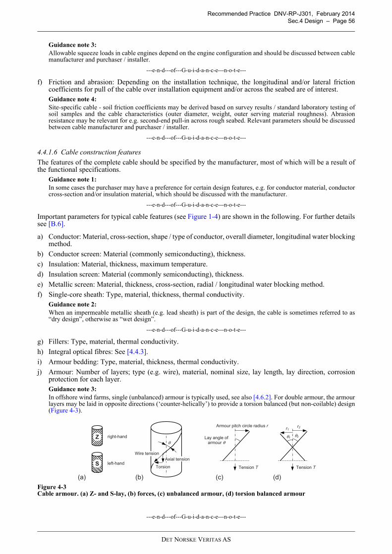
Recommended Practice DNV-RP-J301, February 2014
Sec.4 Design – Page 56
Guidance note 3:
Allowable squeeze loads in cable engines depend on the engine configuration and should be discussed between cablemanufacturer and purchaser / installer.
---e-n-d---of---G-u-i-d-a-n-c-e---n-o-t-e---
f) Friction and abrasion: Depending on the installation technique, the longitudinal and/or lateral frictioncoefficients for pull of the cable over installation equipment and/or across the seabed are of interest.Guidance note 4:
Site-specific cable - soil friction coefficients may be derived based on survey results / standard laboratory testing ofsoil samples and the cable characteristics (outer diameter, weight, outer serving material roughness). Abrasionresistance may be relevant for e.g. second-end pull-in across rough seabed. Relevant parameters should be discussedbetween cable manufacturer and purchaser / installer.
---e-n-d---of---G-u-i-d-a-n-c-e---n-o-t-e---
4.4.1.6 Cable construction features
The features of the complete cable should be specified by the manufacturer, most of which will be a result ofthe functional specifications.
Guidance note 1:
In some cases the purchaser may have a preference for certain design features, e.g. for conductor material, conductorcross-section and/or insulation material, which should be discussed with the manufacturer.
---e-n-d---of---G-u-i-d-a-n-c-e---n-o-t-e---
Important parameters for typical cable features (see Figure 1-4) are shown in the following. For further detailssee [B.6].
a) Conductor: Material, cross-section, shape / type of conductor, overall diameter, longitudinal water blockingmethod.
b) Conductor screen: Material (commonly semiconducting), thickness.
c) Insulation: Material, thickness, maximum temperature.
d) Insulation screen: Material (commonly semiconducting), thickness.
e) Metallic screen: Material, thickness, cross-section, radial / longitudinal water blocking method.
f) Single-core sheath: Type, material, thickness, thermal conductivity.Guidance note 2:
When an impermeable metallic sheath (e.g. lead sheath) is part of the design, the cable is sometimes referred to as“dry design”, otherwise as “wet design”.
---e-n-d---of---G-u-i-d-a-n-c-e---n-o-t-e---
g) Fillers: Type, material, thermal conductivity.
h) Integral optical fibres: See [4.4.3].
i) Armour bedding: Type, material, thickness, thermal conductivity.
j) Armour: Number of layers; type (e.g. wire), material, nominal size, lay length, lay direction, corrosionprotection for each layer.Guidance note 3:
In offshore wind farms, single (unbalanced) armour is typically used, see also [4.6.2]. For double armour, the armourlayers may be laid in opposite directions (‘counter-helically’) to provide a torsion balanced (but non-coilable) design(Figure 4-3).
Figure 4-3Cable armour. (a) Z- and S-lay, (b) forces, (c) unbalanced armour, (d) torsion balanced armour
---e-n-d---of---G-u-i-d-a-n-c-e---n-o-t-e---
θ
Axial tension
Torsion
Wire tension
(a) (b)
Z
S
(c) (d)
θ1θ2
r1r2
Tension T
right-hand
left-hand
Lay angle of armour θ
Armour pitch circle radius r
Tension T
DET NORSKE VERITAS AS
Recommended Practice DNV-RP-J301, February 2014
Sec.4 Design – Page 57
k) Outer serving: Type, material, thickness, thermal conductivity, identification marks (labels, length marking,coloured stripes).
Guidance note 4:
The outer serving can also provide resistance against chemical failure modes including UV-related deterioration andcorrosion. Corrosion impact of seawater onto armouring wires should be considered to retain the cable’s capability towithstand external forces and tensile strength for possible repair work.
---e-n-d---of---G-u-i-d-a-n-c-e---n-o-t-e---
4.4.1.7 Testing specifications
Non-electrical and electrical manufacturing tests for the cables including the applicable standards should beagreed between purchaser and manufacturer, see [5.2].
In addition, the following should be discussed and, if applicable, the necessary information provided by themanufacturer:
— monitoring during load-out, inspection and testing after load-out, inspection and testing after transportation(see [5.3])
— monitoring during installation, testing after installation— testing after commissioning (see [6.9])— monitoring and testing during operation (see [7.3]).
4.4.1.8 Logistical information
The purchaser should specify logistical requirements for the cable project such as:
— place and time of delivery— method of delivery (e.g. on drums / in basket / on turntable, individual cable lengths / continuous length)— cable section lengths, sequence, identification— installation aspects (cable supply only, installation supervision, turnkey supply).
The manufacturer should provide information on the ability to meet the request such as, for instance,production and testing capabilities, availability of production capacity and maximum continuous length ofcable sections.
4.4.2 Power cable accessories
Subsea power cable accessories may include, but not be limited to, the following:
— joints (e.g. single-core / three-core, flexible / rigid), see also [1.3.2] and [6.4.3]— terminations kits, see also [6.9]— cable end caps— hang-off modules, see also [4.7.2.6]— pulling head / stocking.
Joints and terminations should be designed in accordance with applicable IEC standards and CIGRÉguidelines.
Guidance note 1:
For general guidance on accessories for cables with extruded insulation, see CIGRÉ Technical Brochure 177.
---e-n-d---of---G-u-i-d-a-n-c-e---n-o-t-e---
The joints and terminations shall have at least the same electrical strength as the cable itself. Mechanicalproperties of accessories can deviate from those of the cable and should be specified.
The design of the termination kit shall be compatible with the selected power cable design and switch geardesign with regard to selected standards, dimensions and materials.
Guidance note 2:
The termination should also consider the connection of surge arresters, if required, and the connection of a test adapter.
---e-n-d---of---G-u-i-d-a-n-c-e---n-o-t-e---
Normally, the joints and terminations should be of a proven technology. All joints and terminations shall besubjected to a test programme in accordance with the applicable standards, see [5.4].
The design or use of non-electrical accessories such as cable end caps, hang-off modules and pulling devicesshould be confirmed by the cable manufacturer.
4.4.3 Optical fibres
Three-core subsea power cables and some single-core designs may contain a number of optical fibres.
DET NORSKE VERITAS AS

Recommended Practice DNV-RP-J301, February 2014
Sec.4 Design – Page 58
Guidance note 1:
Optical fibres integrated in cables are used for wind farm SCADA, communication, protection relays and cablemonitoring purposes. Fibres for cable monitoring purposes may be of a different type than those for communicationpurposes.Multi-mode fibres (typical wavelength 850 nm) are usable for shorter distances, single-mode fibres (typicalwavelengths 1310 nm and 1550 nm) can be used at long distances.
---e-n-d---of---G-u-i-d-a-n-c-e---n-o-t-e---
The design specification for the integrated fibre optic package should be agreed between purchaser andmanufacturer. Specifications may include, but not be limited to, the following:
— fibre type (single-mode or multi-mode) and operational wavelength— number of fibres, including spare fibres— dimensions and optical properties of single fibres, e.g. attenuation, bending loss— construction of overall fibre optic package (e.g. fibres in metal tube, hydrogen scavenger gel, armour,
sheaths), mechanical properties (e.g. maximum tension, crush load, impact, bending, torsion), waterpenetration
— hybrid solutions, e.g. inclusion of stress sensitive fibres for cable motion monitoring— earthing of metallic parts of fibre optic package— marking of individual fibres, i.e. colour coding scheme— testing standard and special testing requirements.
It shall be possible to connect the optical fibres of different cables using a standard splicing tool.Guidance note 2:
A general expectation for subsea cables is that continuous lengths of optical fibres are used which do not requiresplicing in the power cable factory.
---e-n-d---of---G-u-i-d-a-n-c-e---n-o-t-e---
Splices, connectors and splice/connection boxes shall be available for the optical fibres and suitable for theintended (e.g. offshore) application.
4.5 Cable route
4.5.1 General
Results from the general project layout phase ([3.2]), the desk-based study phase ([3.3]) the cable route surveys([3.4]) and further pertinent information should be used in the detailed cable route engineering process.
Cable route engineering should refine the horizontal (x, y) position of each cable segment as well as its vertical(z) position (on the seabed, buried, protected). For details on cable burial and other protection methods, see[4.6], for details on landfall design, see [4.8].
Key parameters and constraints should be extracted from the design basis ([4.2.4]) or otherwise be defined,preferably in consultation with the installer, including:
— site constraints (slopes, rough terrain)— minimum and/or maximum cable segment lengths— cable constraints (minimum straight segment length between two alter course (A/C) points, on-bottom
tension range)— equipment constraints (minimum on-bottom radius, maximum A/C or arc angle)— distance from existing cables, related to planned equipment and water depth— avoidance of (unnecessary) crossings— preference for straight cable pulls to / from offshore units— temporary laydown areas, e.g. prior to jointing— time restrictions.
Guidance note 1:
In general, bending of an armoured cable in one direction and after a short distance in the other direction should beavoided. To relax the cable, a minimum distance between bends of opposite direction may, for instance, be more than5 m. Such an assumption should be confirmed by the cable manufacturer.
---e-n-d---of---G-u-i-d-a-n-c-e---n-o-t-e---
Based on the identified constraints, the cable route should be designed and optimised, preferably using ageographical information system (GIS) or similar route engineering tool. The preliminary route descriptionshould include, but not be limited to:
— route position list (RPL), acceptable tolerances for the as-laid cable— estimations for burial depth— crossing description, if applicable
DET NORSKE VERITAS AS
Recommended Practice DNV-RP-J301, February 2014
Sec.4 Design – Page 59
— landing description, if applicable— vessel access restrictions, e.g. draught.
Guidance note 2:
For a standardised format for cable route position lists, see ICPC Recommendation 11.
---e-n-d---of---G-u-i-d-a-n-c-e---n-o-t-e---
Detailed cable route design and length calculations for each cable should take the following conditions intoaccount, as applicable:
— end point locations (e.g. wind turbine, offshore substation, landfall, offshore / onshore joints) andtolerances of end point locations
— approach angles for offshore units (also considering “cable free” zones) and landfall— lengths and overlengths required at offshore units (to termination point), cut-off lengths for pulling and
preparation of cable end terminations— length as laid and buried into the seabed, taking into account the bathymetry (slopes), positioning
inaccuracies, potential deviation from / adjustment to the route— crossings with existing infrastructure, commonly perpendicular— installation method, e.g. first- and second-end pull-in— burial method— jointing of cable (or preference to have no joints) and laydown of bight.
The cable route should be further refined in the burial assessment study (see [4.6]), taking into account riskssuch as navigation. Specific aspects are addressed in the following subsections.
4.5.2 Parallel routing of power cables
When power cables are routed in parallel, the distance between them should be subject to careful evaluation.
Guidance note 1:
National or local regulations may require minimum distances to be kept between cables, specifically export cables. Incongested areas of the sea, regulators may also have a preference for maximum cable distances to not unduly limitfuture developments.
---e-n-d---of---G-u-i-d-a-n-c-e---n-o-t-e---
Optimum spacing of two or more power cables should be determined considering project internal and externalfactors.
Guidance note 2:
Factors that influence optimal cable spacing may include those listed in Table 4-2.
Considering safety margins, parallel distances which have been realised in the past were, for instance, 50 m (RedPenguin, 2012) and 100 m. In very shallow waters, allowance may have to be made for the beaching of the cableinstallation vessel when deciding cable spacing. Due to the potentially large number of cables connected to anoffshore substation, the distance between the cables may have to be reduced to several metres in the immediatevicinity of the offshore unit (see Figure 4-12).
Cables, in particular DC poles, may also be bundled and laid in the same trench (reduction factors to their currentcarrying capacity apply).
---e-n-d---of---G-u-i-d-a-n-c-e---n-o-t-e---
Due consideration should be given to the potential repair of a cable. Laydown space requirements for the repairbight depend on water depth, repair vessel deck height, required deck length and crown radius of the bight.Space in addition to the repair bight height (Figure 4-4) may have to be foreseen for future intervention. Whenmore than two cables are routed in parallel, consideration of laydown space for the repair bight become crucial.
Table 4-2 Considerations for optimum cable spacing
Narrower spacing Wider spacing
— minimum corridor width— accommodation of existing constraints, e.g. at
approach to offshore unit or landfall— minimisation of interaction with existing or planned
3rd party infrastructure, avoidance of proximity or crossing agreements
— reduction of the magnetic field and the effect on the environment (in case of two HVDC poles which are not laid in the same trench or bundled, for thermal or other reasons)
— flexibility of route adaptation when encountering difficult ground conditions
— maximise utilisation of space, e.g. for subsequent cable installation
— adequate space for potential repair activities and laydown of repair bight
— greater flexibility in choosing vessel and equipment for intervention (burial, de-burial, cable pick-up)
— risk reduction for multiple cable hits by dragged anchor
DET NORSKE VERITAS AS
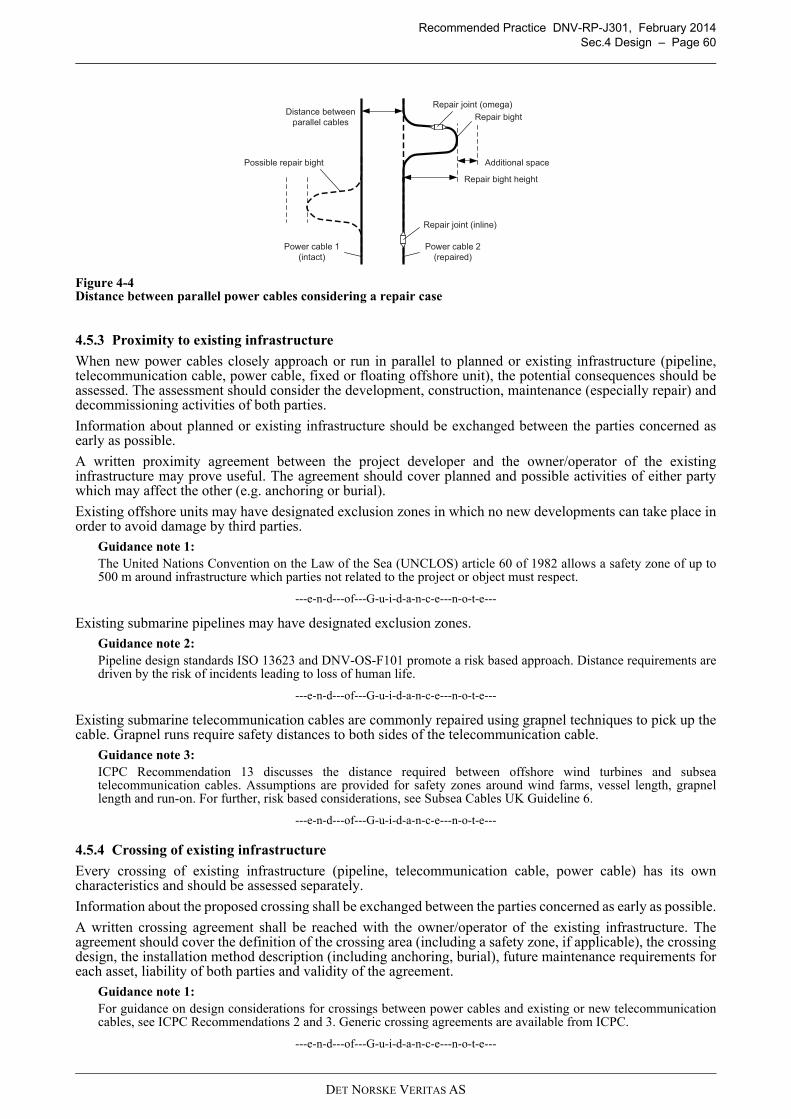
Recommended Practice DNV-RP-J301, February 2014
Sec.4 Design – Page 60
Figure 4-4Distance between parallel power cables considering a repair case
4.5.3 Proximity to existing infrastructure
When new power cables closely approach or run in parallel to planned or existing infrastructure (pipeline,telecommunication cable, power cable, fixed or floating offshore unit), the potential consequences should beassessed. The assessment should consider the development, construction, maintenance (especially repair) anddecommissioning activities of both parties.
Information about planned or existing infrastructure should be exchanged between the parties concerned asearly as possible.
A written proximity agreement between the project developer and the owner/operator of the existinginfrastructure may prove useful. The agreement should cover planned and possible activities of either partywhich may affect the other (e.g. anchoring or burial).
Existing offshore units may have designated exclusion zones in which no new developments can take place inorder to avoid damage by third parties.
Guidance note 1:
The United Nations Convention on the Law of the Sea (UNCLOS) article 60 of 1982 allows a safety zone of up to500 m around infrastructure which parties not related to the project or object must respect.
---e-n-d---of---G-u-i-d-a-n-c-e---n-o-t-e---
Existing submarine pipelines may have designated exclusion zones.
Guidance note 2:
Pipeline design standards ISO 13623 and DNV-OS-F101 promote a risk based approach. Distance requirements aredriven by the risk of incidents leading to loss of human life.
---e-n-d---of---G-u-i-d-a-n-c-e---n-o-t-e---
Existing submarine telecommunication cables are commonly repaired using grapnel techniques to pick up thecable. Grapnel runs require safety distances to both sides of the telecommunication cable.
Guidance note 3:
ICPC Recommendation 13 discusses the distance required between offshore wind turbines and subseatelecommunication cables. Assumptions are provided for safety zones around wind farms, vessel length, grapnellength and run-on. For further, risk based considerations, see Subsea Cables UK Guideline 6.
---e-n-d---of---G-u-i-d-a-n-c-e---n-o-t-e---
4.5.4 Crossing of existing infrastructure
Every crossing of existing infrastructure (pipeline, telecommunication cable, power cable) has its owncharacteristics and should be assessed separately.
Information about the proposed crossing shall be exchanged between the parties concerned as early as possible.
A written crossing agreement shall be reached with the owner/operator of the existing infrastructure. Theagreement should cover the definition of the crossing area (including a safety zone, if applicable), the crossingdesign, the installation method description (including anchoring, burial), future maintenance requirements foreach asset, liability of both parties and validity of the agreement.
Guidance note 1:
For guidance on design considerations for crossings between power cables and existing or new telecommunicationcables, see ICPC Recommendations 2 and 3. Generic crossing agreements are available from ICPC.
---e-n-d---of---G-u-i-d-a-n-c-e---n-o-t-e---
Repair joint (omega)
Additional space
Power cable 1
(intact)
Power cable 2
(repaired)
Repair bight height
Repair joint (inline)
Distance between
parallel cablesRepair bight
Possible repair bight
DET NORSKE VERITAS AS
Recommended Practice DNV-RP-J301, February 2014
Sec.4 Design – Page 61
Considerations concerning the exact crossing location and the design of the crossing shall include thefollowing:
— location (and its uncertainty) of infrastructure— site conditions, e.g. water depth, wave / current action and ground conditions— type and protection of existing infrastructure, e.g. burial depth— type and protection of planned cable— mutual heating of planned cable and existing infrastructure, if applicable— effects of magnetic fields from the new cable onto the existing infrastructure— specific features of existing pipeline (e.g. anodes for cathodic protection) or telecommunication cables (e.g.
repeaters, equalisers, branching units) which require minimum distances to be kept— crossing at approximately right angle (90°) and never less than 45°— service state (in service, out of service) of existing infrastructure and corresponding limitations (e.g. work
near live power cables, pipeline in use)— forming of artificial reef by using protection methods such as mattresses and rock placement— local legislation protecting the existing infrastructure.
Guidance note 2:
New power cables may be laid on top of an existing telecommunication cable or underneath. The latter requires a cutand joint in the telecommunication cable. New telecommunication cables are generally laid over existing powercables.
---e-n-d---of---G-u-i-d-a-n-c-e---n-o-t-e---
The design specification for a crossing shall state requirements concerning:
— minimum (vertical) separation between existing installation and the cable— co-ordinates of crossing— marking of existing installation— confirmation of position and orientation of existing installations on both sides of the crossing— lay-out and profile of crossing— thickness of cover— installation of supporting structures or gravel beds— stability of protection, including methods to prevent scour and erosion around supports— vessel positioning / anchoring— installation / burial techniques and minimum distances including safety zones— monitoring and inspection methods— tolerance requirements, safety margins— any other requirements.
Guidance note 3:
Suitably designed rock berms, also in combination with mattresses and/or bags, have been used for crossings withpipelines, power cables and telecommunication cables.
---e-n-d---of---G-u-i-d-a-n-c-e---n-o-t-e---
4.6 Cable protection
4.6.1 General
During installation, cables shall not be subjected to mechanical loads exceeding the cables’ design limits,including tension, bending, torsion and crushing, see [4.4.1.5]. After installation, for the service life of theproject, cables should be suitably protected from hazards, such as the following:
— marine (waves, tides) and sediment conditions, e.g. exposure and movement of cable— unsupported lengths of cable, e.g. in uneven terrain or due to sand waves— movement of the cable between laying and protection (‘on-bottom stability’), potential for abrasion— penetration of fishing gear, e.g. during bottom-trawling activities— dropped or dragged ship anchors, intended or inadvertent— invasive activities, e.g. dredging— dropped objects, e.g. lost shipment containers or cargo transferred between vessel and offshore unit— seismic activity— ice scour.
Besides safeguarding from hazards, the design of cable protection along the proposed route should notadversely affect the required operational conditions of the cable (e.g. maximum temperature). Protectionsolutions may include the following, including combination of these:
— additional armour ([4.6.2])— burial ([4.6.3])
DET NORSKE VERITAS AS
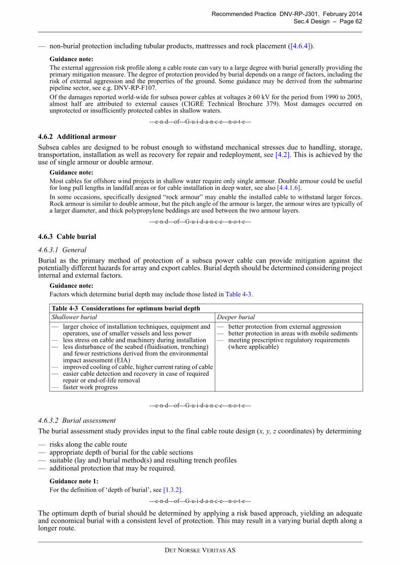
Recommended Practice DNV-RP-J301, February 2014
Sec.4 Design – Page 62
— non-burial protection including tubular products, mattresses and rock placement ([4.6.4]).
Guidance note:
The external aggression risk profile along a cable route can vary to a large degree with burial generally providing theprimary mitigation measure. The degree of protection provided by burial depends on a range of factors, including therisk of external aggression and the properties of the ground. Some guidance may be derived from the submarinepipeline sector, see e.g. DNV-RP-F107.
Of the damages reported world-wide for subsea power cables at voltages ≥ 60 kV for the period from 1990 to 2005,almost half are attributed to external causes (CIGRÉ Technical Brochure 379). Most damages occurred onunprotected or insufficiently protected cables in shallow waters.
---e-n-d---of---G-u-i-d-a-n-c-e---n-o-t-e---
4.6.2 Additional armour
Subsea cables are designed to be robust enough to withstand mechanical stresses due to handling, storage,transportation, installation as well as recovery for repair and redeployment, see [4.2]. This is achieved by theuse of single armour or double armour.
Guidance note:
Most cables for offshore wind projects in shallow water require only single armour. Double armour could be usefulfor long pull lengths in landfall areas or for cable installation in deep water, see also [4.4.1.6].
In some occasions, specifically designed “rock armour” may enable the installed cable to withstand larger forces.Rock armour is similar to double armour, but the pitch angle of the armour is larger, the armour wires are typically ofa larger diameter, and thick polypropylene beddings are used between the two armour layers.
---e-n-d---of---G-u-i-d-a-n-c-e---n-o-t-e---
4.6.3 Cable burial
4.6.3.1 General
Burial as the primary method of protection of a subsea power cable can provide mitigation against thepotentially different hazards for array and export cables. Burial depth should be determined considering projectinternal and external factors.
Guidance note:
Factors which determine burial depth may include those listed in Table 4-3.
---e-n-d---of---G-u-i-d-a-n-c-e---n-o-t-e---
4.6.3.2 Burial assessment
The burial assessment study provides input to the final cable route design (x, y, z coordinates) by determining
— risks along the cable route— appropriate depth of burial for the cable sections— suitable (lay and) burial method(s) and resulting trench profiles— additional protection that may be required.
Guidance note 1:
For the definition of ‘depth of burial’, see [1.3.2].
---e-n-d---of---G-u-i-d-a-n-c-e---n-o-t-e---
The optimum depth of burial should be determined by applying a risk based approach, yielding an adequateand economical burial with a consistent level of protection. This may result in a varying burial depth along alonger route.
Table 4-3 Considerations for optimum burial depth
Shallower burial Deeper burial
— larger choice of installation techniques, equipment and operators, use of smaller vessels and less power
— less stress on cable and machinery during installation— less disturbance of the seabed (fluidisation, trenching)
and fewer restrictions derived from the environmental impact assessment (EIA)
— improved cooling of cable, higher current rating of cable— easier cable detection and recovery in case of required
repair or end-of-life removal— faster work progress
— better protection from external aggression— better protection in areas with mobile sediments— meeting prescriptive regulatory requirements
(where applicable)
DET NORSKE VERITAS AS
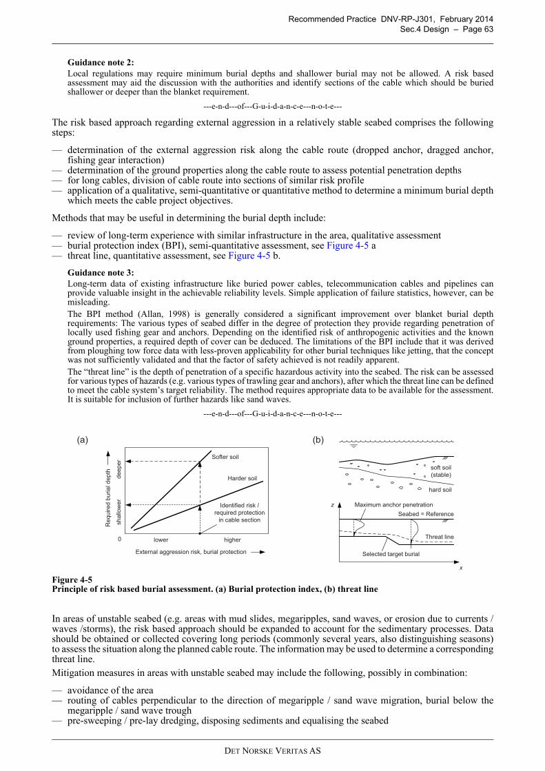
Recommended Practice DNV-RP-J301, February 2014
Sec.4 Design – Page 63
Guidance note 2:
Local regulations may require minimum burial depths and shallower burial may not be allowed. A risk basedassessment may aid the discussion with the authorities and identify sections of the cable which should be buriedshallower or deeper than the blanket requirement.
---e-n-d---of---G-u-i-d-a-n-c-e---n-o-t-e---
The risk based approach regarding external aggression in a relatively stable seabed comprises the followingsteps:
— determination of the external aggression risk along the cable route (dropped anchor, dragged anchor,fishing gear interaction)
— determination of the ground properties along the cable route to assess potential penetration depths— for long cables, division of cable route into sections of similar risk profile— application of a qualitative, semi-quantitative or quantitative method to determine a minimum burial depth
which meets the cable project objectives.
Methods that may be useful in determining the burial depth include:
— review of long-term experience with similar infrastructure in the area, qualitative assessment— burial protection index (BPI), semi-quantitative assessment, see Figure 4-5 a— threat line, quantitative assessment, see Figure 4-5 b.
Guidance note 3:
Long-term data of existing infrastructure like buried power cables, telecommunication cables and pipelines canprovide valuable insight in the achievable reliability levels. Simple application of failure statistics, however, can bemisleading.The BPI method (Allan, 1998) is generally considered a significant improvement over blanket burial depthrequirements: The various types of seabed differ in the degree of protection they provide regarding penetration oflocally used fishing gear and anchors. Depending on the identified risk of anthropogenic activities and the knownground properties, a required depth of cover can be deduced. The limitations of the BPI include that it was derivedfrom ploughing tow force data with less-proven applicability for other burial techniques like jetting, that the conceptwas not sufficiently validated and that the factor of safety achieved is not readily apparent.The “threat line” is the depth of penetration of a specific hazardous activity into the seabed. The risk can be assessedfor various types of hazards (e.g. various types of trawling gear and anchors), after which the threat line can be definedto meet the cable system’s target reliability. The method requires appropriate data to be available for the assessment.It is suitable for inclusion of further hazards like sand waves.
---e-n-d---of---G-u-i-d-a-n-c-e---n-o-t-e---
Figure 4-5Principle of risk based burial assessment. (a) Burial protection index, (b) threat line
In areas of unstable seabed (e.g. areas with mud slides, megaripples, sand waves, or erosion due to currents /waves /storms), the risk based approach should be expanded to account for the sedimentary processes. Datashould be obtained or collected covering long periods (commonly several years, also distinguishing seasons)to assess the situation along the planned cable route. The information may be used to determine a correspondingthreat line.
Mitigation measures in areas with unstable seabed may include the following, possibly in combination:
— avoidance of the area— routing of cables perpendicular to the direction of megaripple / sand wave migration, burial below the
megaripple / sand wave trough— pre-sweeping / pre-lay dredging, disposing sediments and equalising the seabed
Softer soil
External aggression risk, burial protection
Re
qu
ired
bu
ria
l d
ep
th
Harder soil
lower higher
sh
allo
we
rd
ee
pe
r
Identified risk /
required protection
in cable section
0
Selected target burial
Seabed = Reference
x
hard soil
soft soil
(stable)
Threat line
(a) (b)
Maximum anchor penetrationz
DET NORSKE VERITAS AS
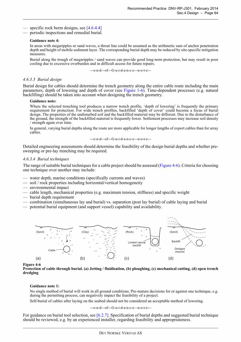
Recommended Practice DNV-RP-J301, February 2014
Sec.4 Design – Page 64
— specific rock berm designs, see [4.6.4.4]— periodic inspections and remedial burial.
Guidance note 4:
In areas with megaripples or sand waves, a threat line could be assumed as the arithmetic sum of anchor penetrationdepth and height of mobile sediment layer. The corresponding burial depth may be reduced by site-specific mitigationmeasures.
Burial along the trough of megaripples / sand waves can provide good long-term protection, but may result in poorcooling due to excessive overburden and in difficult access for future repairs.
---e-n-d---of---G-u-i-d-a-n-c-e---n-o-t-e---
4.6.3.3 Burial design
Burial design for cables should determine the trench geometry along the entire cable route including the mainparameters, depth of lowering and depth of cover (see Figure 1-6). Time-dependent processes (e.g. naturalbackfilling) should be taken into account when designing the trench geometry.
Guidance note:
Where the selected trenching tool produces a narrow trench profile, ‘depth of lowering’ is frequently the primaryrequirement for protection. For wide trench profiles, backfilled ‘depth of cover’ could become a focus of burialdesign. The properties of the undisturbed soil and the backfilled material may be different. Due to the disturbance ofthe ground, the strength of the backfilled material is frequently lower. Settlement processes may increase soil density/ strength again over time.
In general, varying burial depths along the route are more applicable for longer lengths of export cables than for arraycables.
---e-n-d---of---G-u-i-d-a-n-c-e---n-o-t-e---
Detailed engineering assessments should determine the feasibility of the design burial depths and whether pre-sweeping or pre-lay trenching may be required.
4.6.3.4 Burial techniques
The range of suitable burial techniques for a cable project should be assessed (Figure 4-6). Criteria for choosingone technique over another may include:
— water depth, marine conditions (specifically currents and waves)— soil / rock properties including horizontal/vertical homogeneity— environmental impact— cable length, mechanical properties (e.g. maximum tension, stiffness) and specific weight— burial depth requirement— combination (simultaneous lay and burial) vs. separation (post lay burial) of cable laying and burial— potential burial equipment (and support vessel) capability and availability.
Figure 4-6Protection of cable through burial. (a) Jetting / fluidisation, (b) ploughing, (c) mechanical cutting, (d) open trenchdredging
Guidance note 1:
No single method of burial will work in all ground conditions. Pre-mature decisions for or against one technique, e.g.during the permitting process, can negatively impact the feasibility of a project.
Self-burial of cables after laying on the seabed should not be considered an acceptable method of lowering.
---e-n-d---of---G-u-i-d-a-n-c-e---n-o-t-e---
For guidance on burial tool selection, see [6.2.7]. Specification of burial depths and suggested burial techniqueshould be reviewed, e.g. by an experienced installer, regarding feasibility and appropriateness.
(a) (d)
Cable
Backfill
Dredgedchannel
(b) (c)
Limited natural backfill
(Sand) (Rock)(Clay) (Sand)
DET NORSKE VERITAS AS
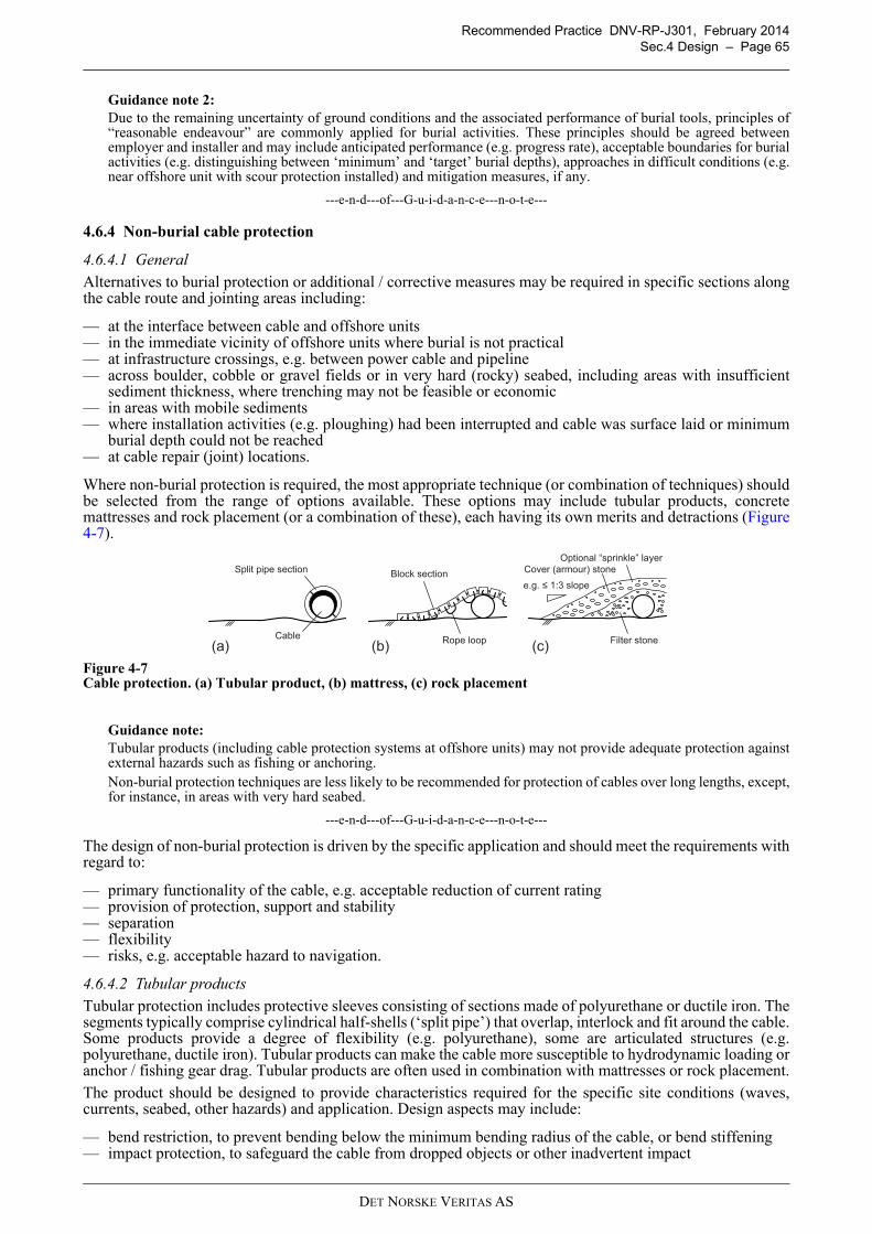
Recommended Practice DNV-RP-J301, February 2014
Sec.4 Design – Page 65
Guidance note 2:
Due to the remaining uncertainty of ground conditions and the associated performance of burial tools, principles of“reasonable endeavour” are commonly applied for burial activities. These principles should be agreed betweenemployer and installer and may include anticipated performance (e.g. progress rate), acceptable boundaries for burialactivities (e.g. distinguishing between ‘minimum’ and ‘target’ burial depths), approaches in difficult conditions (e.g.near offshore unit with scour protection installed) and mitigation measures, if any.
---e-n-d---of---G-u-i-d-a-n-c-e---n-o-t-e---
4.6.4 Non-burial cable protection
4.6.4.1 General
Alternatives to burial protection or additional / corrective measures may be required in specific sections alongthe cable route and jointing areas including:
— at the interface between cable and offshore units— in the immediate vicinity of offshore units where burial is not practical— at infrastructure crossings, e.g. between power cable and pipeline— across boulder, cobble or gravel fields or in very hard (rocky) seabed, including areas with insufficient
sediment thickness, where trenching may not be feasible or economic— in areas with mobile sediments— where installation activities (e.g. ploughing) had been interrupted and cable was surface laid or minimum
burial depth could not be reached— at cable repair (joint) locations.
Where non-burial protection is required, the most appropriate technique (or combination of techniques) shouldbe selected from the range of options available. These options may include tubular products, concretemattresses and rock placement (or a combination of these), each having its own merits and detractions (Figure4-7).
Figure 4-7Cable protection. (a) Tubular product, (b) mattress, (c) rock placement
Guidance note:
Tubular products (including cable protection systems at offshore units) may not provide adequate protection againstexternal hazards such as fishing or anchoring.Non-burial protection techniques are less likely to be recommended for protection of cables over long lengths, except,for instance, in areas with very hard seabed.
---e-n-d---of---G-u-i-d-a-n-c-e---n-o-t-e---
The design of non-burial protection is driven by the specific application and should meet the requirements withregard to:
— primary functionality of the cable, e.g. acceptable reduction of current rating— provision of protection, support and stability— separation— flexibility— risks, e.g. acceptable hazard to navigation.
4.6.4.2 Tubular products
Tubular protection includes protective sleeves consisting of sections made of polyurethane or ductile iron. Thesegments typically comprise cylindrical half-shells (‘split pipe’) that overlap, interlock and fit around the cable.Some products provide a degree of flexibility (e.g. polyurethane), some are articulated structures (e.g.polyurethane, ductile iron). Tubular products can make the cable more susceptible to hydrodynamic loading oranchor / fishing gear drag. Tubular products are often used in combination with mattresses or rock placement.
The product should be designed to provide characteristics required for the specific site conditions (waves,currents, seabed, other hazards) and application. Design aspects may include:
— bend restriction, to prevent bending below the minimum bending radius of the cable, or bend stiffening— impact protection, to safeguard the cable from dropped objects or other inadvertent impact
(c)(b)Filter stone
Cover (armour) stone
(a)
Block sectionSplit pipe section
CableRope loop
e.g. 1:3 slope
Optional “sprinkle” layer
DET NORSKE VERITAS AS
Recommended Practice DNV-RP-J301, February 2014
Sec.4 Design – Page 66
— stability improvement by mass addition— abrasion resistance, to increase life of the cable in high energy / hard seabed environments— durability (e.g. securing half shells by corrosion-free or corrosion-resistant material)— heat conduction, to prevent overheating of the cable during operation— hazard reduction (e.g. smooth outer surface, no protrusions).
Guidance note:
Standard polyurethane is comparably light (adding drag); high density polyurethane has specific weight similar toconcrete. Ductile iron is comparably heavy (adding stability). The design of the tubular product can impact the cableinstallation.
---e-n-d---of---G-u-i-d-a-n-c-e---n-o-t-e---
The installation method permitting, pre-assembly of longer tubular sections onshore can be advantageous. Theinstallation of the tubular product around the cable should be carried out on board the vessel, not by divers(except for remedial work).
4.6.4.3 Mattresses and bags
Mattresses are lattices of segmented, mould-produced blocks of concrete or bitumen connected bypolypropylene ropes which can be laid over a cable to stabilise and shield it, often at cable crossings. Smallsections of the cable or gaps between mattresses may also be protected by pre-filled grout bags or gabion (rockfilled) bags. Concrete shields may be a suitable method of protection for extreme external aggression, e.g. in alandfall area.
The mattress protection should be designed to provide characteristics required for the specific site conditions(waves, currents, seabed, hazards) and application. Design aspects may include:
— hydraulic stability, e.g. through overall weight, increased density and configuration— multi-flexibility, i.e. ability to bend over two axes— over-trawlability through design of the mattress edges (e.g. butt, tapered)— adaptation to scour at the periphery.
Guidance note:
The required density and thickness of a mattress depends on hydrodynamic loading and target impact resistance.
To encourage build-up of sediment material which is suspended and transported in the water column, synthetic frondmats (“artificial seaweed”) may be introduced on top of the mattress and simultaneously installed.
---e-n-d---of---G-u-i-d-a-n-c-e---n-o-t-e---
Where multiple mattresses are to be installed, alignment and “butting up” criteria (tolerances) should beestablished. If applicable, it should be established how gaps between mattresses will be filled (e.g. by groutbags).
The method of deployment should be defined (commonly by crane). Intervention should be diverless;operational limits of remotely operated vehicles (ROVs) shall be taken into account. The required installationframe (or beam) should be designed, certified, inspected and, if applicable, tested according to applicable codesand standards and have a safe working load required for the dynamic conditions during installation.
4.6.4.4 Rock placement
Rock placement is the subsea installation of crushed stones of varying size to form a protective barrier over thecable. Rock placement is e.g. used for scour protection, at infrastructure crossings or where not reachingminimum burial depth left the cable insufficiently protected. Rock berms are relatively resistant againsttrawling and anchoring activities.
Guidance note 1:
Rock covers may be reef and habitat forming, which, depending on area and legislation, may be regarded as a positiveor a negative environmental impact.
---e-n-d---of---G-u-i-d-a-n-c-e---n-o-t-e---
The rock berm should be designed to provide characteristics required for the specific site conditions (waves,currents, seabed, hazards) and application. Design aspects may include:
— long-term hydraulic stability— over-trawlability and protection against dragging anchors (e.g. through choice of slope, rock size)— rock impact energy during installation— adaptation to displacement, e.g. due to weak soil, and scour at the rock berm edges and related maintenance
requirements (e.g. by means of a falling apron)— environmental impact (e.g. limitation of chemical reactions through choice of rock material)— availability of rock, loading facilities, transportation options and times.
DET NORSKE VERITAS AS
Recommended Practice DNV-RP-J301, February 2014
Sec.4 Design – Page 67
Guidance note 2:
Rock berms can be described by their geometry (length, width, profile) including acceptable tolerances, see alsoCIRIA Guideline C683. Layers and grading of rock are typically specified in accordance with EN 13383-1.
---e-n-d---of---G-u-i-d-a-n-c-e---n-o-t-e---
The method of rock installation should be suitable for the product to be deployed with the required profile andaccuracy in the water depth at site. The impact of the falling rock onto the cable (or the cable protection system)should be confirmed to not compromise the cable integrity.
Guidance note 3:
The rock falling speed in the water column depends on installation method, rock grading and density.
---e-n-d---of---G-u-i-d-a-n-c-e---n-o-t-e---
4.7 Cable interface at fixed offshore units
4.7.1 General
The design of the interface between a subsea cable and a fixed offshore unit shall take conditions and limitsduring installation (primarily mechanical) and after installation (electrical, thermal, mechanical) into account.
Guidance note:
Offshore units comprise offshore platforms (e.g. AC transformer station, HVDC converter station) and offshorerenewable generators (e.g. offshore wind turbines). Examples of interfaces shown, e.g. in Figure 4-8 and Figure 4-11,are for illustration.
---e-n-d---of---G-u-i-d-a-n-c-e---n-o-t-e---
4.7.2 Offshore unit
4.7.2.1 Field layout
In the vicinity of offshore units where cables terminate, the cable layout should be optimised, avoidingcongestion of cables and enabling installation, including burial and non-burial protection.
Guidance note 1:
A layout optimised for installability does not necessarily result in the shortest cable lengths. The de-riskingnevertheless normally lowers overall project cost as a reduction in vessel time can more than compensate for a smallincrease in cable length.The direction of approach to offshore units should take other users of the interface area at/near the offshore unit intoconsideration. A perpendicular approach often eases installation and minimises installation forces, see also [4.7.3].
---e-n-d---of---G-u-i-d-a-n-c-e---n-o-t-e---
Restrictions at / near offshore units like jack-up “cable free” zones shall be respected. Conversely, “no jack-up” zones should provide adequate space for cable routing.
Guidance note 2:
Punch holes left by jack-up vessels can make routing of cables across difficult and should be avoided, where possible.Furthermore, scour may be encouraged around the jack-up legs and in the area of the punch holes. After cableinstallation, the use of jack-up vessels in close proximity to the cable increases the risk of damage and should beavoided where possible.
---e-n-d---of---G-u-i-d-a-n-c-e---n-o-t-e---
4.7.2.2 Access
Access of personnel and transfer of cable installation, termination and testing equipment to the offshore unitshould be considered in the design.
Guidance note 1:
Access to the offshore unit can often be a limiting factor for installation progress. Reduction in requirements to accessthe offshore unit or improvement of the access system / method can result in more cost effective projects.A davit or other type of crane with a source of power is normally required on each offshore unit to safely transfer anycargo such as equipment, tools and parts.
---e-n-d---of---G-u-i-d-a-n-c-e---n-o-t-e---
Different design options should be considered. The choice of design should meet the objectives described inSec.2.
Guidance note 2:
Different design options exist for the interface between the seabed-mounted substructure and the topsides. When acable deck is part of the substructure (Figure 4-8 a), the subsea cables can be pulled in prior to installation of thetopsides, decoupling installation steps. Typically cables cannot be pulled to final length in one step, but attachment ofan approved pulling stocking and pull of additional length will be required. Laydown space should be provided,
DET NORSKE VERITAS AS
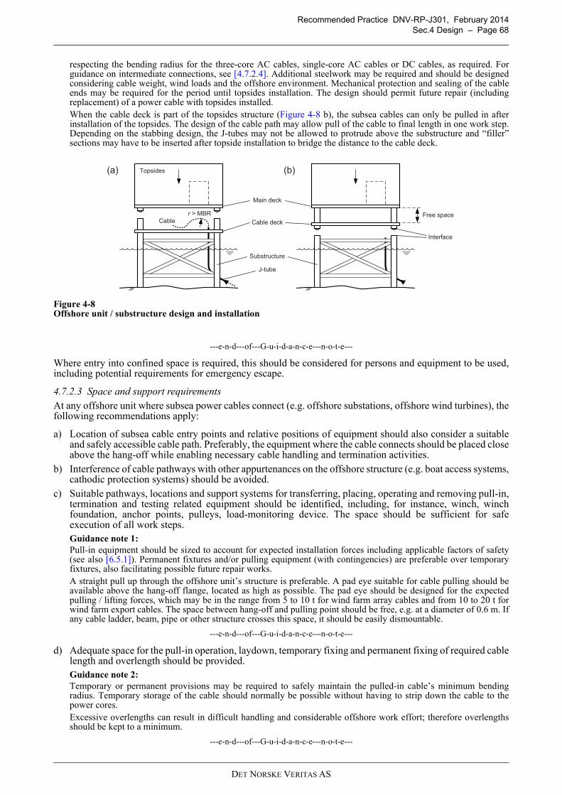
Recommended Practice DNV-RP-J301, February 2014
Sec.4 Design – Page 68
respecting the bending radius for the three-core AC cables, single-core AC cables or DC cables, as required. Forguidance on intermediate connections, see [4.7.2.4]. Additional steelwork may be required and should be designedconsidering cable weight, wind loads and the offshore environment. Mechanical protection and sealing of the cableends may be required for the period until topsides installation. The design should permit future repair (includingreplacement) of a power cable with topsides installed.When the cable deck is part of the topsides structure (Figure 4-8 b), the subsea cables can only be pulled in afterinstallation of the topsides. The design of the cable path may allow pull of the cable to final length in one work step.Depending on the stabbing design, the J-tubes may not be allowed to protrude above the substructure and “filler”sections may have to be inserted after topside installation to bridge the distance to the cable deck.
Figure 4-8Offshore unit / substructure design and installation
---e-n-d---of---G-u-i-d-a-n-c-e---n-o-t-e---
Where entry into confined space is required, this should be considered for persons and equipment to be used,including potential requirements for emergency escape.
4.7.2.3 Space and support requirements
At any offshore unit where subsea power cables connect (e.g. offshore substations, offshore wind turbines), thefollowing recommendations apply:
a) Location of subsea cable entry points and relative positions of equipment should also consider a suitableand safely accessible cable path. Preferably, the equipment where the cable connects should be placed closeabove the hang-off while enabling necessary cable handling and termination activities.
b) Interference of cable pathways with other appurtenances on the offshore structure (e.g. boat access systems,cathodic protection systems) should be avoided.
c) Suitable pathways, locations and support systems for transferring, placing, operating and removing pull-in,termination and testing related equipment should be identified, including, for instance, winch, winchfoundation, anchor points, pulleys, load-monitoring device. The space should be sufficient for safeexecution of all work steps.Guidance note 1:
Pull-in equipment should be sized to account for expected installation forces including applicable factors of safety(see also [6.5.1]). Permanent fixtures and/or pulling equipment (with contingencies) are preferable over temporaryfixtures, also facilitating possible future repair works.A straight pull up through the offshore unit’s structure is preferable. A pad eye suitable for cable pulling should beavailable above the hang-off flange, located as high as possible. The pad eye should be designed for the expectedpulling / lifting forces, which may be in the range from 5 to 10 t for wind farm array cables and from 10 to 20 t forwind farm export cables. The space between hang-off and pulling point should be free, e.g. at a diameter of 0.6 m. Ifany cable ladder, beam, pipe or other structure crosses this space, it should be easily dismountable.
---e-n-d---of---G-u-i-d-a-n-c-e---n-o-t-e---
d) Adequate space for the pull-in operation, laydown, temporary fixing and permanent fixing of required cablelength and overlength should be provided.Guidance note 2:
Temporary or permanent provisions may be required to safely maintain the pulled-in cable’s minimum bendingradius. Temporary storage of the cable should normally be possible without having to strip down the cable to thepower cores.Excessive overlengths can result in difficult handling and considerable offshore work effort; therefore overlengthsshould be kept to a minimum.
---e-n-d---of---G-u-i-d-a-n-c-e---n-o-t-e---
Topsides
Main deck
Cable deckCable
J-tube
Substructure
(a) (b)
Free space
Interface
r > MBR
DET NORSKE VERITAS AS
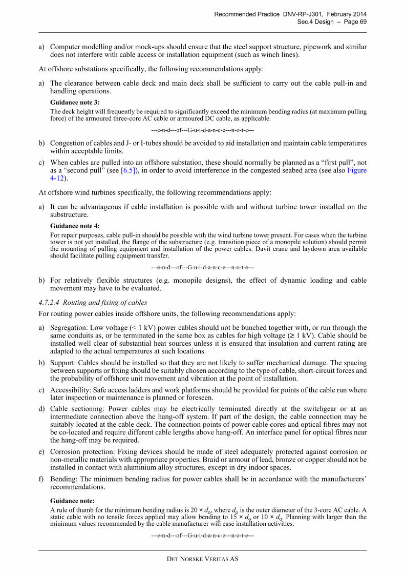
Recommended Practice DNV-RP-J301, February 2014
Sec.4 Design – Page 69
a) Computer modelling and/or mock-ups should ensure that the steel support structure, pipework and similardoes not interfere with cable access or installation equipment (such as winch lines).
At offshore substations specifically, the following recommendations apply:
a) The clearance between cable deck and main deck shall be sufficient to carry out the cable pull-in andhandling operations.
Guidance note 3:
The deck height will frequently be required to significantly exceed the minimum bending radius (at maximum pullingforce) of the armoured three-core AC cable or armoured DC cable, as applicable.
---e-n-d---of---G-u-i-d-a-n-c-e---n-o-t-e---
b) Congestion of cables and J- or I-tubes should be avoided to aid installation and maintain cable temperatureswithin acceptable limits.
c) When cables are pulled into an offshore substation, these should normally be planned as a “first pull”, notas a “second pull” (see [6.5]), in order to avoid interference in the congested seabed area (see also Figure4-12).
At offshore wind turbines specifically, the following recommendations apply:
a) It can be advantageous if cable installation is possible with and without turbine tower installed on thesubstructure.
Guidance note 4:
For repair purposes, cable pull-in should be possible with the wind turbine tower present. For cases when the turbinetower is not yet installed, the flange of the substructure (e.g. transition piece of a monopile solution) should permitthe mounting of pulling equipment and installation of the power cables. Davit crane and laydown area availableshould facilitate pulling equipment transfer.
---e-n-d---of---G-u-i-d-a-n-c-e---n-o-t-e---
b) For relatively flexible structures (e.g. monopile designs), the effect of dynamic loading and cablemovement may have to be evaluated.
4.7.2.4 Routing and fixing of cables
For routing power cables inside offshore units, the following recommendations apply:
a) Segregation: Low voltage (< 1 kV) power cables should not be bunched together with, or run through thesame conduits as, or be terminated in the same box as cables for high voltage (≥ 1 kV). Cable should beinstalled well clear of substantial heat sources unless it is ensured that insulation and current rating areadapted to the actual temperatures at such locations.
b) Support: Cables should be installed so that they are not likely to suffer mechanical damage. The spacingbetween supports or fixing should be suitably chosen according to the type of cable, short-circuit forces andthe probability of offshore unit movement and vibration at the point of installation.
c) Accessibility: Safe access ladders and work platforms should be provided for points of the cable run wherelater inspection or maintenance is planned or foreseen.
d) Cable sectioning: Power cables may be electrically terminated directly at the switchgear or at anintermediate connection above the hang-off system. If part of the design, the cable connection may besuitably located at the cable deck. The connection points of power cable cores and optical fibres may notbe co-located and require different cable lengths above hang-off. An interface panel for optical fibres nearthe hang-off may be required.
e) Corrosion protection: Fixing devices should be made of steel adequately protected against corrosion ornon-metallic materials with appropriate properties. Braid or armour of lead, bronze or copper should not beinstalled in contact with aluminium alloy structures, except in dry indoor spaces.
f) Bending: The minimum bending radius for power cables shall be in accordance with the manufacturers’recommendations.
Guidance note:
A rule of thumb for the minimum bending radius is 20 × do, where do is the outer diameter of the 3-core AC cable. Astatic cable with no tensile forces applied may allow bending to 15 × do or 10 × do. Planning with larger than theminimum values recommended by the cable manufacturer will ease installation activities.
---e-n-d---of---G-u-i-d-a-n-c-e---n-o-t-e---
DET NORSKE VERITAS AS
Recommended Practice DNV-RP-J301, February 2014
Sec.4 Design – Page 70
4.7.2.5 Penetration of walls and decks
Where cables penetrate walls or decks (above the water level), the following recommendations apply:
a) Integrity: Penetrations should meet the fire and watertight integrity of the wall or deck.Guidance note:
Use of cables with low emission of smoke in case of a fire should be considered for all indoor sections. The risk offire and other environmental harms should be evaluated in a project-specific risk assessment.
---e-n-d---of---G-u-i-d-a-n-c-e---n-o-t-e---
b) Thermal insulation: Cable runs should not be laid in or covered with thermal insulation, but may crossthrough such insulation.
c) Chafing: Penetrations of walls and decks should be such that the cables are not chafed.d) Mechanical support of penetrations: Except for cable hang-off, penetrations should be designed so that they
do not take up forces caused by the offshore unit’s movements, vibrations and temperature variations.e) Temporary seals: Penetrations through outer walls should be adequately sealed for temporary phases until
cable installation.
4.7.2.6 Cable hang-off
Where cables are secured by hang-off systems, the following recommendations apply:
a) The hang-off should securely anchor the cable by transferring all mechanical loads from the armour to thestructure for the design life of the cable system without compromising the integrity of the cable. The stresson the armour wires should remain in a range avoiding premature wear and yielding.Guidance note 1:
Hang-off modules are often split into a temporary part (based on friction between a clamp and the outer sheath of thecable, installed first) and a permanent part (based on e.g. bending and clamping of the armour wires, installed later),see Figure 4-9. The temporary hang-off can quickly secure the cable after pull-in (and normally stays in placeafterwards), while the permanent hang-off supports the cable for its operational lifetime. The temporary hang-offsecures the cable sufficiently for cable installation works to proceed. The permanent hang-off is required prior toelectrical termination of the cable.
Figure 4-9Typical design of cable hang-off
---e-n-d---of---G-u-i-d-a-n-c-e---n-o-t-e---
b) The hang-off design should allow the implementation of the earthing design, see [3.2.4.3].
c) The device should account for the cable-integrated or bundled fibre-optic cable.
d) The hang-off should be designed to provide the required level of sealing.Guidance note 2:
Air-tight sealing may be required for health and safety reasons (to avoid gases from below entering work areas) or toprevent the exchange of air (to limit the oxygen content below and reduce corrosion rates).
---e-n-d---of---G-u-i-d-a-n-c-e---n-o-t-e---
e) The hang-off should be easily installable.
Guidance note 3:
No scaffolding should be required for the installation of the hang-off system, see also [4.7.2.3]. The hang-off weightand dimensions should preferably be in a range so that installation without a crane is possible.
---e-n-d---of---G-u-i-d-a-n-c-e---n-o-t-e---
Armour wire
Deck
Permanent hang-off(armour wires)
Cable outer sheath
Cable inner sheath
Temporary hang-off(friction based)
(to seabed)
(to termination)
DET NORSKE VERITAS AS
Recommended Practice DNV-RP-J301, February 2014
Sec.4 Design – Page 71
4.7.2.7 Single-core cables
For routing single cores of AC circuits (and for DC installations with high “ripple” content) at an offshore unitabove the hang-off, the following recommendations apply:
a) Armour on single-core cables should normally be of non-magnetic type. Typically the non-magneticarmour is earthed at one end.
b) Single-core cables belonging to the same circuit should be laid as close as possible and preferably in atriangular (trefoil) formation. They should be contained within the same pipe, conduit or trunk. Clamps thatfix them should, if possible, include all phases.
c) Phases belonging to the same circuit should not be separated by magnetic material and be run together in acommon wall penetration (multi cable transit), unless the penetration system is of non-magnetic material.
d) In order to guard against the effects of electro-dynamic forces developing on the occurrence of a shortcircuit or earth fault, single-core cables should be firmly fixed, using supports of strength adequate towithstand the dynamic forces.
4.7.2.8 Cable termination
All equipment shall be provided with suitable, fixed terminals in an accessible position with sufficient spacefor dismantling and connection of external incoming cables.
Optical fibres contained within the power cable should be terminated in suitable boxes / cabinets which provideadequate space for splicing and are designed for offshore use.
At the location where cables are terminated, the following recommendations apply:
a) The layout at the cable interface shall not compromise the minimum bending radius of the cable, allow foraccess as required and provide sufficient and safe working space.Guidance note 1:
The design should avoid using scaffolding or temporary ladders for installation and/or maintenance activities on thehigh voltage cores or optical fibres as they complicate logistics and increase health and safety risks for terminationpersonnel, see also [4.7.2.3].
---e-n-d---of---G-u-i-d-a-n-c-e---n-o-t-e---
b) Cable entry into the enclosure should provide effective sealing.
c) All connections for current-carrying parts and earthing connections should be fixed so that they cannotloosen by vibration.
d) Disconnectable power cable terminations should preferably have the female part of the termination andinsulator included in the switchgear cable chamber, facilitating hermetical sealing of the switchgearchamber.
e) Suitable earth connection points should be provided for fixing bonding leads from cable terminations orcable screen.
f) Electrical testing of cables should be facilitated by inclusion of suitable bushings or cable test sockets inthe design.Guidance note 2:
Where clearances required for an open terminal bushing cannot be achieved, power cables may potentially be testedthrough the connected switchgear.In order to carry out certain high voltage tests on cables, it may be necessary to disconnect switchgear voltagetransformers and surge arrestors. If required, this should be incorporated in the design.
---e-n-d---of---G-u-i-d-a-n-c-e---n-o-t-e---
4.7.3 Interface between cable and offshore unit
4.7.3.1 General
When designing the interface between cable and offshore unit, the following shall be considered:
— cable’s (and cable protection system’s) mechanical and thermal properties— heat build-up in the cable guiding systems due to cable losses and exposure to direct sun light— adequate sizing of tubes and their supports to achieve acceptable cable pull-in forces and cooling of the
cable— preference for straight path and avoidance of multiple bends, to minimise installation forces— smoothness of the surface the cable will be in contact with during pull-in, chafing-proof tube ends— operational and accidental impacts, e.g. from service vessels— stiffening of substructure the tube is mounted to (requiring sectioning of the tube)— corrosion protection of the cable armour and cable supporting elements
DET NORSKE VERITAS AS
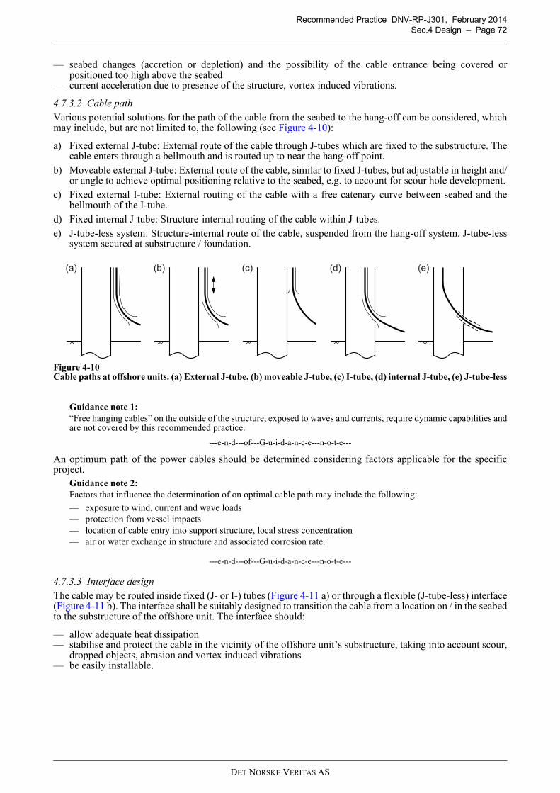
Recommended Practice DNV-RP-J301, February 2014
Sec.4 Design – Page 72
— seabed changes (accretion or depletion) and the possibility of the cable entrance being covered orpositioned too high above the seabed
— current acceleration due to presence of the structure, vortex induced vibrations.
4.7.3.2 Cable path
Various potential solutions for the path of the cable from the seabed to the hang-off can be considered, whichmay include, but are not limited to, the following (see Figure 4-10):
a) Fixed external J-tube: External route of the cable through J-tubes which are fixed to the substructure. Thecable enters through a bellmouth and is routed up to near the hang-off point.
b) Moveable external J-tube: External route of the cable, similar to fixed J-tubes, but adjustable in height and/or angle to achieve optimal positioning relative to the seabed, e.g. to account for scour hole development.
c) Fixed external I-tube: External routing of the cable with a free catenary curve between seabed and thebellmouth of the I-tube.
d) Fixed internal J-tube: Structure-internal routing of the cable within J-tubes.
e) J-tube-less system: Structure-internal route of the cable, suspended from the hang-off system. J-tube-lesssystem secured at substructure / foundation.
Figure 4-10Cable paths at offshore units. (a) External J-tube, (b) moveable J-tube, (c) I-tube, (d) internal J-tube, (e) J-tube-less
Guidance note 1:
“Free hanging cables” on the outside of the structure, exposed to waves and currents, require dynamic capabilities andare not covered by this recommended practice.
---e-n-d---of---G-u-i-d-a-n-c-e---n-o-t-e---
An optimum path of the power cables should be determined considering factors applicable for the specificproject.
Guidance note 2:
Factors that influence the determination of on optimal cable path may include the following:
— exposure to wind, current and wave loads— protection from vessel impacts— location of cable entry into support structure, local stress concentration— air or water exchange in structure and associated corrosion rate.
---e-n-d---of---G-u-i-d-a-n-c-e---n-o-t-e---
4.7.3.3 Interface design
The cable may be routed inside fixed (J- or I-) tubes (Figure 4-11 a) or through a flexible (J-tube-less) interface(Figure 4-11 b). The interface shall be suitably designed to transition the cable from a location on / in the seabedto the substructure of the offshore unit. The interface should:
— allow adequate heat dissipation— stabilise and protect the cable in the vicinity of the offshore unit’s substructure, taking into account scour,
dropped objects, abrasion and vortex induced vibrations— be easily installable.
(a) (e)(c)(b) (d)
DET NORSKE VERITAS AS
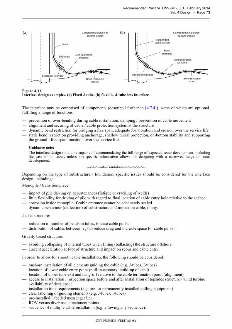
Recommended Practice DNV-RP-J301, February 2014
Sec.4 Design – Page 73
Figure 4-11Interface design examples. (a) Fixed J-tube, (b) flexible, J-tube-less interface
The interface may be comprised of components (described further in [4.7.4]), some of which are optional,fulfilling a range of functions:
— prevention of over-bending during cable installation, damping / prevention of cable movement— alignment and securing of cable / cable protection system at the structure— dynamic bend restriction for bridging a free span, adequate for vibration and erosion over the service life— static bend restriction providing anchorage, shallow burial protection, on-bottom stability and supporting
the ground - free span transition over the service life.
Guidance note:
The interface design should be capable of accommodating the full range of expected scour development, includingthe case of no scour, unless site-specific information allows for designing with a narrowed range of scourdevelopment.
---e-n-d---of---G-u-i-d-a-n-c-e---n-o-t-e---
Depending on the type of substructure / foundation, specific issues should be considered for the interfacedesign, including:
Monopile / transition piece:
— impact of pile driving on appurtenances (fatigue or cracking of welds)— little flexibility for driving of pile with regard to final location of cable entry hole relative to the seabed— corrosion inside monopile if cable entrance cannot be adequately sealed— dynamic behaviour (deflection) of substructure and impact on cable, if any.
Jacket structure:
— reduction of number of bends in tubes, to ease cable pull-in— distribution of cables between legs to reduce drag and increase space for cable pull-in.
Gravity based structure:
— avoiding collapsing of internal tubes when filling (ballasting) the structure offshore— current acceleration at foot of structure and impact on scour and cable entry.
In order to allow for smooth cable installation, the following should be considered:
— onshore installation of all elements guiding the cable (e.g. J-tubes, I-tubes)— location of lower cable entry point (pull-in catenary, build-up of sand)— location of upper tube exit and hang-off relative to the cable termination point (alignment)— access to installation / inspection space before and after installation of topsides structure / wind turbine— availability of deck space— installation time requirements (e.g. pre- or permanently installed pulling equipment)— clear labelling of guiding elements (e.g. J-tubes, I-tubes)— pre-installed, labelled messenger line— ROV versus diver use, attachment points— sequence of multiple cable installation (e.g. allowing any sequence).
(a) (b)
Suspended cable section
Bend
stiffening
Bend restriction(static)
Bellmouth
J-tube
Structural interface
Components subject to
specific design
Bend restriction(dynamic)
Bend restriction(static)
Bend restriction(dynamic)
Structural interface
Components subject to
specific design
DET NORSKE VERITAS AS
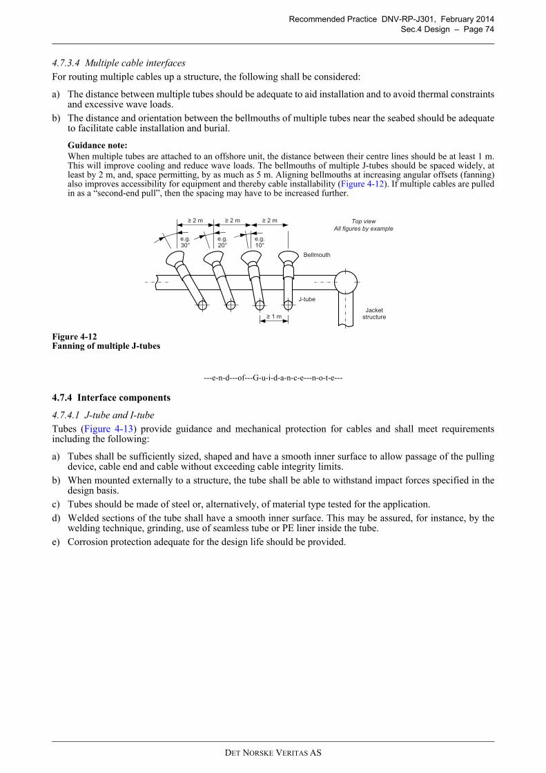
Recommended Practice DNV-RP-J301, February 2014
Sec.4 Design – Page 74
4.7.3.4 Multiple cable interfaces
For routing multiple cables up a structure, the following shall be considered:
a) The distance between multiple tubes should be adequate to aid installation and to avoid thermal constraintsand excessive wave loads.
b) The distance and orientation between the bellmouths of multiple tubes near the seabed should be adequateto facilitate cable installation and burial.
Guidance note:
When multiple tubes are attached to an offshore unit, the distance between their centre lines should be at least 1 m.This will improve cooling and reduce wave loads. The bellmouths of multiple J-tubes should be spaced widely, atleast by 2 m, and, space permitting, by as much as 5 m. Aligning bellmouths at increasing angular offsets (fanning)also improves accessibility for equipment and thereby cable installability (Figure 4-12). If multiple cables are pulledin as a “second-end pull”, then the spacing may have to be increased further.
Figure 4-12Fanning of multiple J-tubes
---e-n-d---of---G-u-i-d-a-n-c-e---n-o-t-e---
4.7.4 Interface components
4.7.4.1 J-tube and I-tube
Tubes (Figure 4-13) provide guidance and mechanical protection for cables and shall meet requirementsincluding the following:
a) Tubes shall be sufficiently sized, shaped and have a smooth inner surface to allow passage of the pullingdevice, cable end and cable without exceeding cable integrity limits.
b) When mounted externally to a structure, the tube shall be able to withstand impact forces specified in thedesign basis.
c) Tubes should be made of steel or, alternatively, of material type tested for the application.
d) Welded sections of the tube shall have a smooth inner surface. This may be assured, for instance, by thewelding technique, grinding, use of seamless tube or PE liner inside the tube.
e) Corrosion protection adequate for the design life should be provided.
Top view
All figures by example
2 m 2 m 2 m
e.g. 10°
e.g. 20°
e.g. 30°
J-tube
Jacketstructure
Bellmouth
1 m
DET NORSKE VERITAS AS
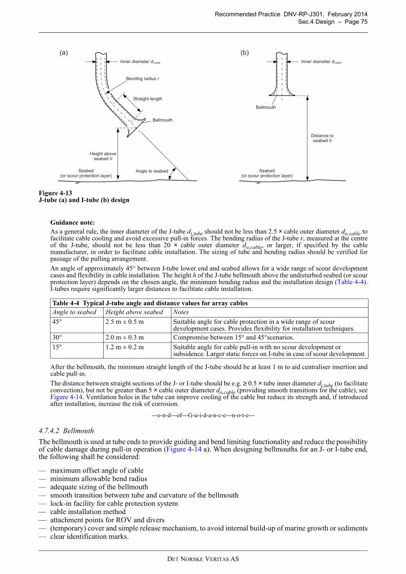
Recommended Practice DNV-RP-J301, February 2014
Sec.4 Design – Page 75
4.13
Figure 4-13J-tube (a) and I-tube (b) design
Guidance note:
As a general rule, the inner diameter of the J-tube di,tube should not be less than 2.5 × cable outer diameter do,cable tofacilitate cable cooling and avoid excessive pull-in forces. The bending radius of the J-tube r, measured at the centreof the J-tube, should not be less than 20 × cable outer diameter do,cable, or larger, if specified by the cablemanufacturer, in order to facilitate cable installation. The sizing of tube and bending radius should be verified forpassage of the pulling arrangement.
An angle of approximately 45° between J-tube lower end and seabed allows for a wide range of scour developmentcases and flexibility in cable installation. The height h of the J-tube bellmouth above the undisturbed seabed (or scourprotection layer) depends on the chosen angle, the minimum bending radius and the installation design (Table 4-4).I-tubes require significantly larger distances to facilitate cable installation.
After the bellmouth, the minimum straight length of the J-tube should be at least 1 m to aid centraliser insertion andcable pull-in.
The distance between straight sections of the J- or I-tube should be e.g. ≥ 0.5 × tube inner diameter di,tube (to facilitateconvection), but not be greater than 5 × cable outer diameter do,cable (providing smooth transitions for the cable), seeFigure 4-14. Ventilation holes in the tube can improve cooling of the cable but reduce its strength and, if introducedafter installation, increase the risk of corrosion.
---e-n-d---of---G-u-i-d-a-n-c-e---n-o-t-e---
4.7.4.2 Bellmouth
The bellmouth is used at tube ends to provide guiding and bend limiting functionality and reduce the possibilityof cable damage during pull-in operation (Figure 4-14 a). When designing bellmouths for an J- or I-tube end,the following shall be considered:
— maximum offset angle of cable— minimum allowable bend radius— adequate sizing of the bellmouth— smooth transition between tube and curvature of the bellmouth— lock-in facility for cable protection system— cable installation method— attachment points for ROV and divers— (temporary) cover and simple release mechanism, to avoid internal build-up of marine growth or sediments— clear identification marks.
Table 4-4 Typical J-tube angle and distance values for array cables
Angle to seabed Height above seabed Notes
45° 2.5 m ± 0.5 m Suitable angle for cable protection in a wide range of scour development cases. Provides flexibility for installation techniques.
30° 2.0 m ± 0.3 m Compromise between 15° and 45°scenarios.
15° 1.2 m ± 0.2 m Suitable angle for cable pull-in with no scour development or subsidence. Larger static forces on J-tube in case of scour development.
Angle to seabed
Straight length
Height above seabed h
Seabed(or scour protection layer)
(a)
Bellmouth
Bending radius r
Inner diameter di,tube
Distance to seabed h
(b)
Bellmouth
Inner diameter di,tube
Seabed(or scour protection layer)
DET NORSKE VERITAS AS
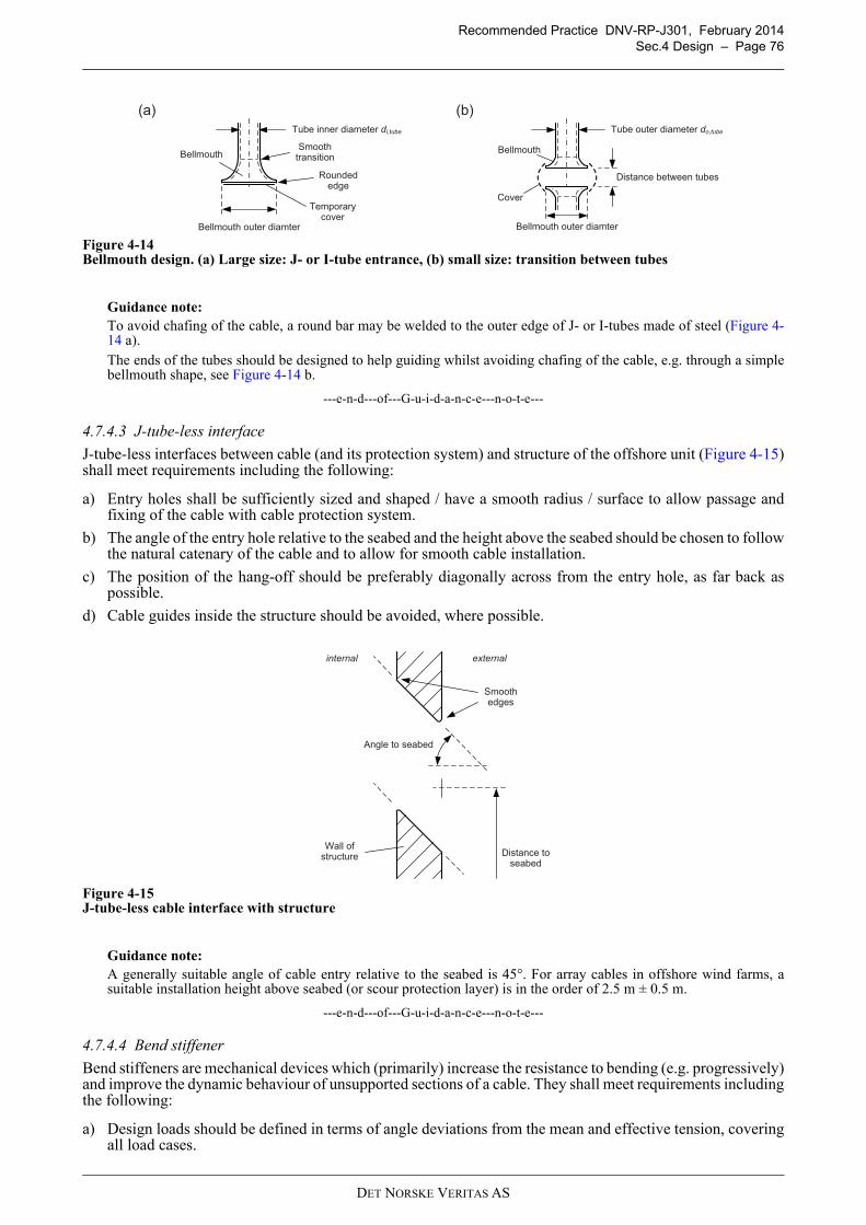
Recommended Practice DNV-RP-J301, February 2014
Sec.4 Design – Page 76
Figure 4-14Bellmouth design. (a) Large size: J- or I-tube entrance, (b) small size: transition between tubes
Guidance note:
To avoid chafing of the cable, a round bar may be welded to the outer edge of J- or I-tubes made of steel (Figure 4-14 a).
The ends of the tubes should be designed to help guiding whilst avoiding chafing of the cable, e.g. through a simplebellmouth shape, see Figure 4-14 b.
---e-n-d---of---G-u-i-d-a-n-c-e---n-o-t-e---
4.7.4.3 J-tube-less interface
J-tube-less interfaces between cable (and its protection system) and structure of the offshore unit (Figure 4-15)shall meet requirements including the following:
a) Entry holes shall be sufficiently sized and shaped / have a smooth radius / surface to allow passage andfixing of the cable with cable protection system.
b) The angle of the entry hole relative to the seabed and the height above the seabed should be chosen to followthe natural catenary of the cable and to allow for smooth cable installation.
c) The position of the hang-off should be preferably diagonally across from the entry hole, as far back aspossible.
d) Cable guides inside the structure should be avoided, where possible.
Figure 4-15J-tube-less cable interface with structure
Guidance note:
A generally suitable angle of cable entry relative to the seabed is 45°. For array cables in offshore wind farms, asuitable installation height above seabed (or scour protection layer) is in the order of 2.5 m ± 0.5 m.
---e-n-d---of---G-u-i-d-a-n-c-e---n-o-t-e---
4.7.4.4 Bend stiffener
Bend stiffeners are mechanical devices which (primarily) increase the resistance to bending (e.g. progressively)and improve the dynamic behaviour of unsupported sections of a cable. They shall meet requirements includingthe following:
a) Design loads should be defined in terms of angle deviations from the mean and effective tension, coveringall load cases.
Smoothtransition
Distance between tubes
Bellmouth outer diamter
Bellmouth
Tube inner diameter di,tube
Bellmouth outer diamter
Bellmouth
Tube outer diameter do,tube
(a) (b)
Temporarycover
Cover
Roundededge
Angle to seabed
Smooth edges
Distance toseabed
externalinternal
Wall ofstructure
DET NORSKE VERITAS AS

Recommended Practice DNV-RP-J301, February 2014
Sec.4 Design – Page 77
b) The design methodology should consider possible failure modes, including rupture, ageing, fatigue andend-fitting failure.
c) The bend stiffener should be manufactured from materials selected for the specific environment, e.g.polymer (elastomeric) material.
Guidance note:
Bend stiffeners are often made of polyurethane. For design guidance on bend stiffeners, see ISO 13628-2, AppendixB.
---e-n-d---of---G-u-i-d-a-n-c-e---n-o-t-e---
4.7.4.5 Bend restrictor
Bend restrictors are mechanical devices which limit the bending of a cable to a minimum value. They shall meetrequirements including the following:
a) Design loads should be defined in terms of bending moments, shear forces and impact loads (whereapplicable, e.g. for rock placement).
b) The design methodology should consider ageing and end-fitting failure.
c) A bend restrictor shall lock before the minimum bending radius of the cable is reached. The device shallprovide smooth support of the cable without sharp edges.
d) Bend restrictor elements may be manufactured from elastomers, fibre reinforced plastic or metallicmaterials, which shall be selected for the specific environment and have sufficient corrosion resistance.
Guidance note:
Bend restrictors are often made of polyurethane or ductile iron. For design guidance on bend restrictors, see ISO13628-2, Appendix B.
---e-n-d---of---G-u-i-d-a-n-c-e---n-o-t-e---
4.7.4.6 Entry seal
Where a power cable enters the structure of an offshore unit, a seal between cable and structure is sometimesused.
Guidance note:
Sealing can reduce seawater exchange inside the submerged part of the structure in order to lower corrosion rates.Sealing can make power cable installation and repair difficult, therefore designs without seals may be preferable.
---e-n-d---of---G-u-i-d-a-n-c-e---n-o-t-e---
If used, the seal should meet requirements including the following:
a) Where the purpose of the seal is to limit or block seawater exchange to reduce corrosion, the allowed rateof exchange should be specified (depending on sealing differential pressure) and the design should bedemonstrated to meet the specification.
b) The seal should be easy to fit during installation and allow exchange of the power cable in case of repair.
4.7.4.7 Latching / anchoring mechanism
A latching / anchoring mechanism may hold a cable protection system in place after installation. If used, themechanism should meet requirements including the following:
a) The mechanism should maintain the cable protection system in place under the designed environmentalconditions.
b) The mechanism should be easy to install. The latch should be removable, preferably without the use ofdivers.
c) The mechanism should not prevent an exchange of the power cable in case of repair.
4.7.4.8 Tube centraliser
Centralisers provide a local increase in cable diameter, limiting the cable’s lateral movement inside a tube.When used in the bellmouth of J- and I-tubes in power cable applications, centralisers should meetrequirements including the following:
a) The centraliser should maintain the position of the cable within the tube.
b) Centraliser and J-tube bend should be designed together so that the minimum bending radius of the cablecannot be compromised during pull-in.
c) The centraliser should be easy to fit during installation. The clamping pressure shall not exceed the limitsof the cable.
DET NORSKE VERITAS AS
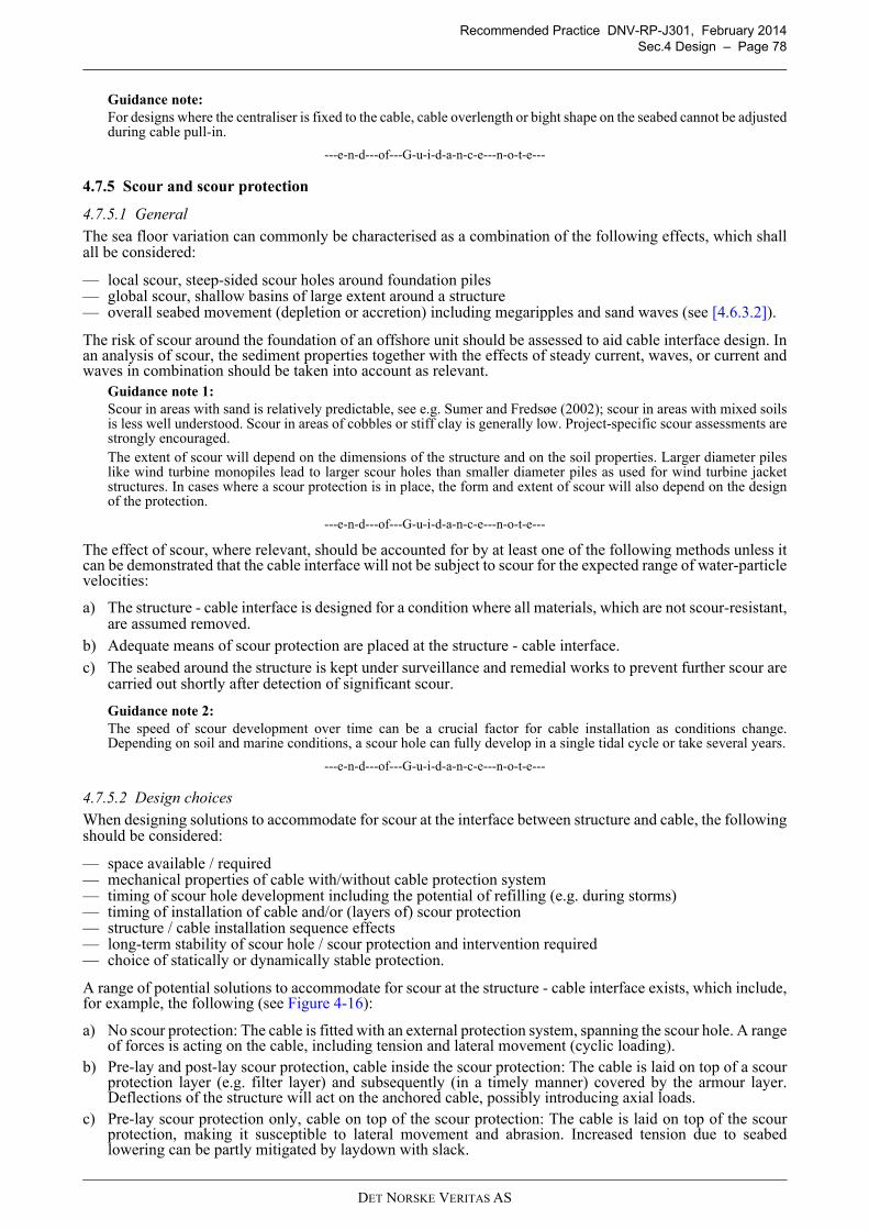
Recommended Practice DNV-RP-J301, February 2014
Sec.4 Design – Page 78
Guidance note:
For designs where the centraliser is fixed to the cable, cable overlength or bight shape on the seabed cannot be adjustedduring cable pull-in.
---e-n-d---of---G-u-i-d-a-n-c-e---n-o-t-e---
4.7.5 Scour and scour protection
4.7.5.1 General
The sea floor variation can commonly be characterised as a combination of the following effects, which shallall be considered:
— local scour, steep-sided scour holes around foundation piles— global scour, shallow basins of large extent around a structure— overall seabed movement (depletion or accretion) including megaripples and sand waves (see [4.6.3.2]).
The risk of scour around the foundation of an offshore unit should be assessed to aid cable interface design. Inan analysis of scour, the sediment properties together with the effects of steady current, waves, or current andwaves in combination should be taken into account as relevant.
Guidance note 1:
Scour in areas with sand is relatively predictable, see e.g. Sumer and Fredsøe (2002); scour in areas with mixed soilsis less well understood. Scour in areas of cobbles or stiff clay is generally low. Project-specific scour assessments arestrongly encouraged.The extent of scour will depend on the dimensions of the structure and on the soil properties. Larger diameter pileslike wind turbine monopiles lead to larger scour holes than smaller diameter piles as used for wind turbine jacketstructures. In cases where a scour protection is in place, the form and extent of scour will also depend on the designof the protection.
---e-n-d---of---G-u-i-d-a-n-c-e---n-o-t-e---
The effect of scour, where relevant, should be accounted for by at least one of the following methods unless itcan be demonstrated that the cable interface will not be subject to scour for the expected range of water-particlevelocities:
a) The structure - cable interface is designed for a condition where all materials, which are not scour-resistant,are assumed removed.
b) Adequate means of scour protection are placed at the structure - cable interface.
c) The seabed around the structure is kept under surveillance and remedial works to prevent further scour arecarried out shortly after detection of significant scour.
Guidance note 2:
The speed of scour development over time can be a crucial factor for cable installation as conditions change.Depending on soil and marine conditions, a scour hole can fully develop in a single tidal cycle or take several years.
---e-n-d---of---G-u-i-d-a-n-c-e---n-o-t-e---
4.7.5.2 Design choices
When designing solutions to accommodate for scour at the interface between structure and cable, the followingshould be considered:
— space available / required— mechanical properties of cable with/without cable protection system— timing of scour hole development including the potential of refilling (e.g. during storms)— timing of installation of cable and/or (layers of) scour protection— structure / cable installation sequence effects— long-term stability of scour hole / scour protection and intervention required— choice of statically or dynamically stable protection.
A range of potential solutions to accommodate for scour at the structure - cable interface exists, which include,for example, the following (see Figure 4-16):
a) No scour protection: The cable is fitted with an external protection system, spanning the scour hole. A rangeof forces is acting on the cable, including tension and lateral movement (cyclic loading).
b) Pre-lay and post-lay scour protection, cable inside the scour protection: The cable is laid on top of a scourprotection layer (e.g. filter layer) and subsequently (in a timely manner) covered by the armour layer.Deflections of the structure will act on the anchored cable, possibly introducing axial loads.
c) Pre-lay scour protection only, cable on top of the scour protection: The cable is laid on top of the scourprotection, making it susceptible to lateral movement and abrasion. Increased tension due to seabedlowering can be partly mitigated by laydown with slack.
DET NORSKE VERITAS AS
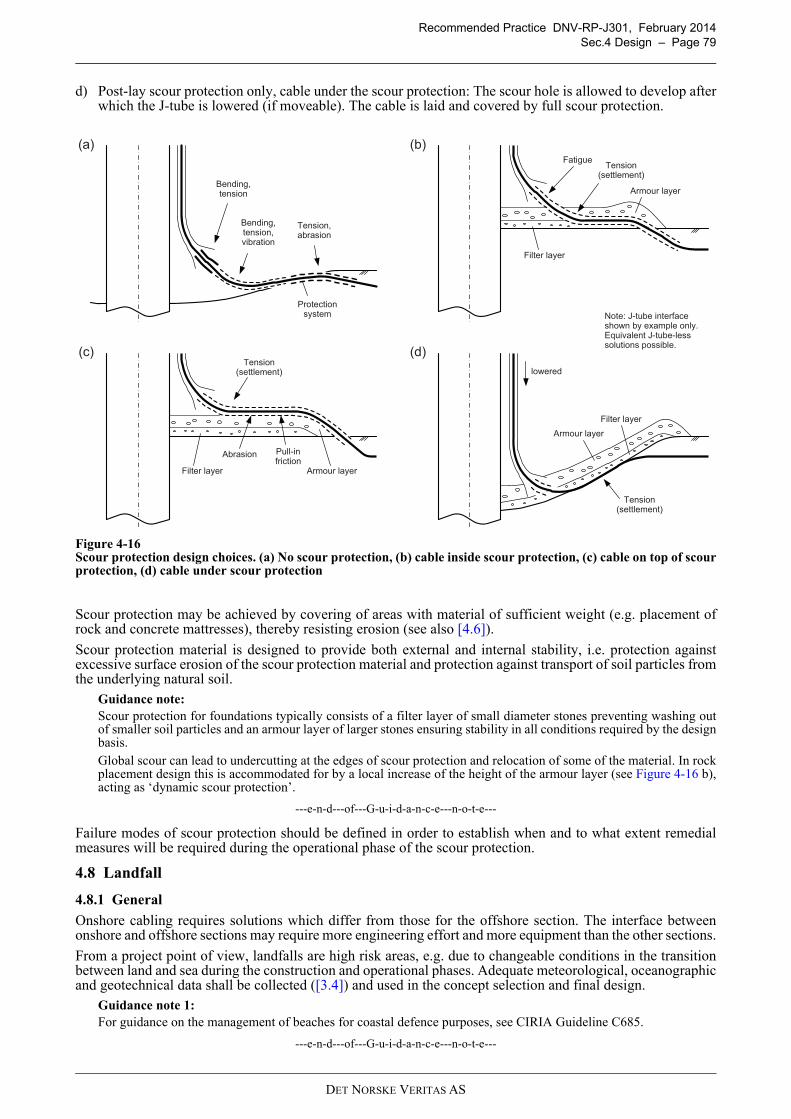
Recommended Practice DNV-RP-J301, February 2014
Sec.4 Design – Page 79
d) Post-lay scour protection only, cable under the scour protection: The scour hole is allowed to develop afterwhich the J-tube is lowered (if moveable). The cable is laid and covered by full scour protection.
Figure 4-16Scour protection design choices. (a) No scour protection, (b) cable inside scour protection, (c) cable on top of scourprotection, (d) cable under scour protection
Scour protection may be achieved by covering of areas with material of sufficient weight (e.g. placement ofrock and concrete mattresses), thereby resisting erosion (see also [4.6]).
Scour protection material is designed to provide both external and internal stability, i.e. protection againstexcessive surface erosion of the scour protection material and protection against transport of soil particles fromthe underlying natural soil.
Guidance note:
Scour protection for foundations typically consists of a filter layer of small diameter stones preventing washing outof smaller soil particles and an armour layer of larger stones ensuring stability in all conditions required by the designbasis.Global scour can lead to undercutting at the edges of scour protection and relocation of some of the material. In rockplacement design this is accommodated for by a local increase of the height of the armour layer (see Figure 4-16 b),acting as ‘dynamic scour protection’.
---e-n-d---of---G-u-i-d-a-n-c-e---n-o-t-e---
Failure modes of scour protection should be defined in order to establish when and to what extent remedialmeasures will be required during the operational phase of the scour protection.
4.8 Landfall
4.8.1 General
Onshore cabling requires solutions which differ from those for the offshore section. The interface betweenonshore and offshore sections may require more engineering effort and more equipment than the other sections.
From a project point of view, landfalls are high risk areas, e.g. due to changeable conditions in the transitionbetween land and sea during the construction and operational phases. Adequate meteorological, oceanographicand geotechnical data shall be collected ([3.4]) and used in the concept selection and final design.
Guidance note 1:
For guidance on the management of beaches for coastal defence purposes, see CIRIA Guideline C685.
---e-n-d---of---G-u-i-d-a-n-c-e---n-o-t-e---
Note: J-tube interface shown by example only. Equivalent J-tube-less solutions possible.
(d)
Tension(settlement)
Filter layer
Armour layer
(b)
Tension(settlement)
Filter layer
Armour layer
(c)Tension
(settlement)
Filter layer Armour layer
Pull-infriction
Fatigue
Abrasion
lowered
(a)
Bending,tension
Bending,tension,vibration
Tension,abrasion
Protection system
DET NORSKE VERITAS AS
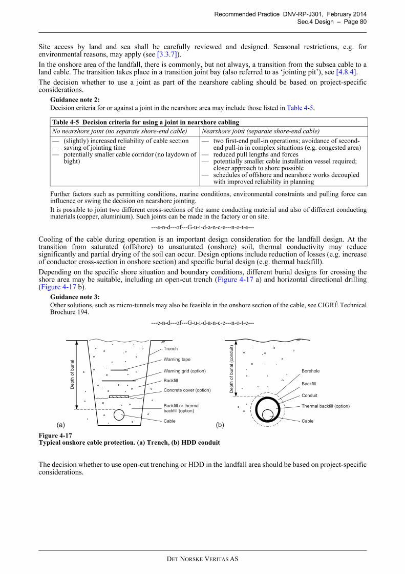
Recommended Practice DNV-RP-J301, February 2014
Sec.4 Design – Page 80
4.17
Site access by land and sea shall be carefully reviewed and designed. Seasonal restrictions, e.g. forenvironmental reasons, may apply (see [3.3.7]).
In the onshore area of the landfall, there is commonly, but not always, a transition from the subsea cable to aland cable. The transition takes place in a transition joint bay (also referred to as ‘jointing pit’), see [4.8.4].
The decision whether to use a joint as part of the nearshore cabling should be based on project-specificconsiderations.
Guidance note 2:
Decision criteria for or against a joint in the nearshore area may include those listed in Table 4-5.
Further factors such as permitting conditions, marine conditions, environmental constraints and pulling force caninfluence or swing the decision on nearshore jointing.It is possible to joint two different cross-sections of the same conducting material and also of different conductingmaterials (copper, aluminium). Such joints can be made in the factory or on site.
---e-n-d---of---G-u-i-d-a-n-c-e---n-o-t-e---
Cooling of the cable during operation is an important design consideration for the landfall design. At thetransition from saturated (offshore) to unsaturated (onshore) soil, thermal conductivity may reducesignificantly and partial drying of the soil can occur. Design options include reduction of losses (e.g. increaseof conductor cross-section in onshore section) and specific burial design (e.g. thermal backfill).
Depending on the specific shore situation and boundary conditions, different burial designs for crossing theshore area may be suitable, including an open-cut trench (Figure 4-17 a) and horizontal directional drilling(Figure 4-17 b).
Guidance note 3:
Other solutions, such as micro-tunnels may also be feasible in the onshore section of the cable, see CIGRÉ TechnicalBrochure 194.
---e-n-d---of---G-u-i-d-a-n-c-e---n-o-t-e---
Figure 4-17Typical onshore cable protection. (a) Trench, (b) HDD conduit
The decision whether to use open-cut trenching or HDD in the landfall area should be based on project-specificconsiderations.
Table 4-5 Decision criteria for using a joint in nearshore cabling
No nearshore joint (no separate shore-end cable) Nearshore joint (separate shore-end cable)
— (slightly) increased reliability of cable section— saving of jointing time— potentially smaller cable corridor (no laydown of
bight)
— two first-end pull-in operations; avoidance of second-end pull-in in complex situations (e.g. congested area)
— reduced pull lengths and forces— potentially smaller cable installation vessel required;
closer approach to shore possible— schedules of offshore and nearshore works decoupled
with improved reliability in planning
De
pth
of
bu
rial
(a)Cable
Trench
Warning tape
Warning grid (option)
Concrete cover (option)
Backfill
(b)
De
pth
of
bu
rial (c
ond
uit)
Cable
Conduit
Thermal backfill (option)
Borehole
Backfill
Backfill or thermal backfill (option)
DET NORSKE VERITAS AS

Recommended Practice DNV-RP-J301, February 2014
Sec.4 Design – Page 81
Guidance note 4:
Factors influencing the decision for open-cut trenching or HDD may include those listed in Table 4-6.
---e-n-d---of---G-u-i-d-a-n-c-e---n-o-t-e---
The design should allow for long-term effects such as beach erosion when specifying target values. In thenorthern hemisphere, significant beach erosion can occur in winter.
4.8.2 Open-cut trench
Open-cut trenching is a cable protection technique where the trench is cut prior to cable laying. For geo-hazardsand site investigation techniques which should be considered to lower risks to an acceptable level, see [3.4].
Potential trench paths should be evaluated considering boundary conditions such as the following:
— geological formation, strata, hazards in the area, water table, thermal properties— existing infrastructure— existing and future use of the area, e.g. for agricultural activities including ploughing— site access, also for equipment— environmental and permitting concerns.
Trench design in onshore sections is often guided by local regulations. Critical features shall be determined atthe design stage, including the following (see also Figure 4-17 a):
a) Path: The trench routing should be relatively straight to keep cable pulling forces low. The use of powered,synchronised rollers can reduce or eliminate the concern.
b) Corridor width: The corridor should provide sufficient space for and adequate trench cross-section design,temporary storage of excavated material and a work access road.
c) Trench cross-section: The trench width depends on the number of cables laid into the same trench. Cablemanufacturers’ recommendation for minimum separation should be followed. Electrical faults shall becontained to ensure safety of the public. Trench slopes should be designed for the site-specific groundconditions to avoid collapse.Guidance note:
The depth of cover is frequently in the 0.6 m to 1.0 m range for land-based cables, but in shore areas more may berequired depending on the identified risks. Covers of concrete mats have also been used, both in intertidal andnearshore areas.
---e-n-d---of---G-u-i-d-a-n-c-e---n-o-t-e---
d) Cable bedding: The immediate cable surroundings largely influence the cooling of the cable duringoperation. The bedding material should have suitable mechanical and thermal properties.
e) Warning measures: The risk of damage by third party excavation works should be assessed and suitablecountermeasures be introduced. Depending on the location of the cable section and the identified risk level,these may include concrete covers, protection grids and (almost always) brightly coloured warning tapes(see Figure 4-17 a). Reporting of underground works is a common requirement in most countries.
Trench design is an iterative process. Location of the water table and potential drying out of backfill materialare important design considerations. Cross-checks should be performed to confirm that the cooling of the cablewill be ensured under operational conditions.
4.8.3 Horizontal directional drilling
Horizontal directional drilling (HDD) is a trenchless method of installing pipes and cables underground alonga planned shallow arc trajectory. The geological formation of the landfall area shall be reviewed to determinewhether HDD is technically feasible. For geo-hazards and site investigation techniques which should beconsidered to lower risks to an acceptable level, see [3.4].
Potential HDD trajectories should be evaluated considering boundary conditions such as the following (Figure4-18):
— minimum, maximum distance to be drilled
Table 4-6 Potential benefits of open-cut trenching and HDD
Open-cut trenching HDD
— suitable for beaches that can be excavated— use of standard construction equipment— relatively inexpensive— good access to cable in case of repair
— suitable for shores with high cliffs, hard rock or highly erosive character
— undercrossing of sea defence systems (e.g. sea walls, dikes, dunes)
— low environmental impact, avoidance of surface contaminated zones
DET NORSKE VERITAS AS
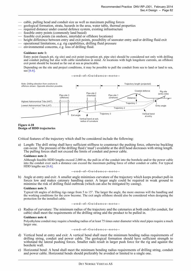
Recommended Practice DNV-RP-J301, February 2014
Sec.4 Design – Page 82
4.18
— cable, pulling head and conduit size as well as maximum pulling forces— geological formation, strata, hazards in the area, water table, thermal properties— required distance under coastal defence system, existing infrastructure— feasible entry points (commonly land based)— feasible exit points (in onshore, intertidal or offshore locations)— height difference between entry and exit points, possibility of seawater entry and/or drilling fluid exit— operational limitations, e.g. rig capabilities, drilling fluid pressure— environmental concerns, e.g. loss of drilling fluid.
Guidance note 1:
Entry point (launch pit, rig site) and exit point (reception pit, pipe site) should be considered not only with drillingand conduit pulling but also with cable installation in mind. At locations with high longshore currents, an offshoreexit point should be located as far out at sea as practicable.Depending on the site and project conditions, it may be possible to pull the conduit from sea to land or land to sea,see [6.6].
---e-n-d---of---G-u-i-d-a-n-c-e---n-o-t-e---
Figure 4-18Design of HDD trajectories
Critical features of the trajectory which shall be considered include the following:
a) Length: The drill string shall have sufficient stiffness to counteract the pushing force, otherwise bucklingcan occur. The pressure of the drilling fluid (‘mud’) available at the drill head decreases with string length.The pulling forces shall not exceed the limits of conduit and power cable.Guidance note 2:
Although feasible HDD lengths exceed 2,000 m, the pull-in of the conduit into the borehole and/or the power cableinto the conduit over such a distance can exceed the maximum pulling force of either conduit or cable. For typicalHDD lengths see [6.6].
---e-n-d---of---G-u-i-d-a-n-c-e---n-o-t-e---
b) Angle at entry and exit: A smaller angle minimises curvature of the trajectory which keeps product pull-inforces low and makes catenary handling easier. A larger angle could be required in weak ground tominimise the risk of drilling fluid outbreak (which can also be mitigated by casing).Guidance note 3:
Typical tilt angles of drilling rigs range from 5 to 15°. The larger the angle, the more onerous will the handling andthe working conditions for the crew become. The exit angle offshore should also be considered when designing theprotection for the installed cable.
---e-n-d---of---G-u-i-d-a-n-c-e---n-o-t-e---
c) Radius of curvature: The minimum radius of the trajectory and the catenaries at both ends (for conduit, forcable) shall meet the requirements of the drilling string and the product to be pulled in.Guidance note 4:
Polyethylene conduit may require a bending radius of at least 75 times outer diameter while steel pipes require a muchlarger one.
---e-n-d---of---G-u-i-d-a-n-c-e---n-o-t-e---
d) Vertical bend at entry and exit: A vertical bend shall meet the minimum bending radius requirements ofdrilling string, conduit and power cable. The geological formation should have sufficient strength towithstand the lateral pushing forces. Smaller radii result in larger push force for the rig and against theborehole wall.
e) Horizontal bend: A bend shall meet the minimum bending radius requirements of drilling string, conduitand power cable. Horizontal bends should preferably be avoided or limited to a single one.
Highest Astronomical Tide (HAT)
Lowest Astronomical Tide (LAT)
Rig site(entry side)
Trajectory 1
Trajectory 2
Trajectory 3
Coastal defence
Distance
Pipe site 1(onshore)
Pipe site 2(intertidal)Pipe site 3
(offshore)
Note: Drilling direction from onshore to offshore shown. Opposite direction possible.
Vertical bend at entry
Vertical bend at exit,radius of curvature
Entry angle
Exit angle
Trajectory length (projected)
DET NORSKE VERITAS AS
Recommended Practice DNV-RP-J301, February 2014
Sec.4 Design – Page 83
The transition between saturated and unsaturated soil will typically occur along the HDD trajectory. At thispoint cooling of the cable may be poor due to low thermal conductivity of the conduit and soil as well as largeburial depth. Thermal properties along the planned trajectory should be determined to aid power cable currentrating calculations. The conduit properties to be determined should include (see also Figure 4-17 b):
a) Conduit material: Typical materials are polyethylene (light, flexible, less expensive, low thermalconductivity) and steel (heavy, stiff, more expensive, high thermal conductivity).
b) Inner diameter of the conduit: Most commonly only one cable is installed in a conduit. Consideringparameters such as pulling arrangement, cable weight, pull length, friction coefficient and bends, theminimum inner diameter of the conduit should be determined.Guidance note 5:
With a typical HDD curvature, an inner conduit diameter di,conduit of 1.5 × cable outer diameter do,cable can beadequate, while factors close to 2.5 are rarely required.
---e-n-d---of---G-u-i-d-a-n-c-e---n-o-t-e---
c) Conduit strength: Based on the required inner diameter, adequate wall thickness of the conduit shouldensure that it can be installed with the predicted pull-in forces.
d) Borehole size: The borehole size should be adequate for the chosen conduit, also considering the expectedgeological conditions.Guidance note 6:
Typical borehole sizes are in the range of 1.25 to 1.5 × outer conduit diameter do,conduit.
---e-n-d---of---G-u-i-d-a-n-c-e---n-o-t-e---
HDD and conduit design is an iterative process. Cross-checks should be performed to confirm that the predictedpulling forces do not exceed the cable’s maximum tensile load (or whether additional armour may be required)and that the cooling of the cable will be ensured during operational conditions.
4.8.4 Onshore jointing location
The onshore jointing location (also referred to as ‘transition joint bay’, ‘joint transition pit’ or ‘interface joiningpit’) is an important interface between onshore works and beach / offshore works. Functions of the jointtransition bay may include:
— mechanical fixation of power cables— interface joint between un-armoured land power cable(s) and armoured subsea power cable(s)— splice point for optical fibres— earthing point.
The jointing location should be designed to:
— provide a safe and stable temporary working area— have space for winches behind the transition joint bay and for adequate overlength of cables to be pulled in— allow securing the cables mechanically— allow for the provision of a conditioned environment for jointing activities (e.g. dewatering, air
conditioning)— enable cable commissioning and testing— if required, provide accessibility for future inspections.
Guidance note:
Location of the transition joint bay onshore and above the water table can facilitate installation activities, inspectionsand fault locating. A location below the water table or offshore can provide improved thermal performance, butinstallation and maintenance activities will be more difficult to perform.
---e-n-d---of---G-u-i-d-a-n-c-e---n-o-t-e---
The design should be accepted by onshore and offshore installers, including the party responsible for jointing.
DET NORSKE VERITAS AS
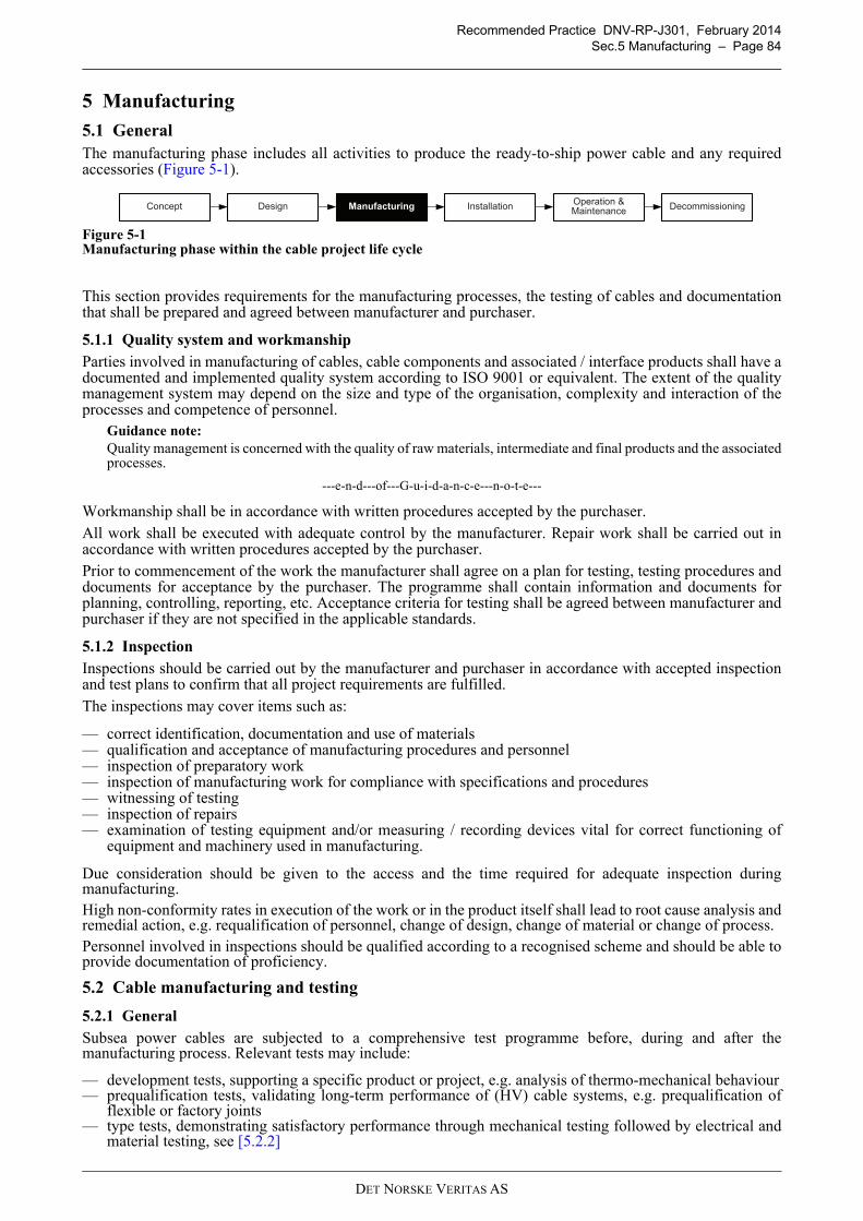
Recommended Practice DNV-RP-J301, February 2014
Sec.5 Manufacturing – Page 84
5 Manufacturing
5.1 General
The manufacturing phase includes all activities to produce the ready-to-ship power cable and any requiredaccessories (Figure 5-1).
Figure 5-1Manufacturing phase within the cable project life cycle
This section provides requirements for the manufacturing processes, the testing of cables and documentationthat shall be prepared and agreed between manufacturer and purchaser.
5.1.1 Quality system and workmanship
Parties involved in manufacturing of cables, cable components and associated / interface products shall have adocumented and implemented quality system according to ISO 9001 or equivalent. The extent of the qualitymanagement system may depend on the size and type of the organisation, complexity and interaction of theprocesses and competence of personnel.
Guidance note:
Quality management is concerned with the quality of raw materials, intermediate and final products and the associatedprocesses.
---e-n-d---of---G-u-i-d-a-n-c-e---n-o-t-e---
Workmanship shall be in accordance with written procedures accepted by the purchaser.
All work shall be executed with adequate control by the manufacturer. Repair work shall be carried out inaccordance with written procedures accepted by the purchaser.
Prior to commencement of the work the manufacturer shall agree on a plan for testing, testing procedures anddocuments for acceptance by the purchaser. The programme shall contain information and documents forplanning, controlling, reporting, etc. Acceptance criteria for testing shall be agreed between manufacturer andpurchaser if they are not specified in the applicable standards.
5.1.2 Inspection
Inspections should be carried out by the manufacturer and purchaser in accordance with accepted inspectionand test plans to confirm that all project requirements are fulfilled.
The inspections may cover items such as:
— correct identification, documentation and use of materials— qualification and acceptance of manufacturing procedures and personnel— inspection of preparatory work— inspection of manufacturing work for compliance with specifications and procedures— witnessing of testing— inspection of repairs— examination of testing equipment and/or measuring / recording devices vital for correct functioning of
equipment and machinery used in manufacturing.
Due consideration should be given to the access and the time required for adequate inspection duringmanufacturing.High non-conformity rates in execution of the work or in the product itself shall lead to root cause analysis andremedial action, e.g. requalification of personnel, change of design, change of material or change of process.Personnel involved in inspections should be qualified according to a recognised scheme and should be able toprovide documentation of proficiency.
5.2 Cable manufacturing and testing
5.2.1 General
Subsea power cables are subjected to a comprehensive test programme before, during and after themanufacturing process. Relevant tests may include:
— development tests, supporting a specific product or project, e.g. analysis of thermo-mechanical behaviour— prequalification tests, validating long-term performance of (HV) cable systems, e.g. prequalification of
flexible or factory joints— type tests, demonstrating satisfactory performance through mechanical testing followed by electrical and
material testing, see [5.2.2]
DesignConceptOperation & Maintenance
Installation DecommissioningManufacturing
DET NORSKE VERITAS AS
Recommended Practice DNV-RP-J301, February 2014
Sec.5 Manufacturing – Page 85
— sample tests, representing the manufacturing process of the cable, see [5.2.3]— routine tests, verifying that the product meets specifications, including tests on manufactured cable lengths,
tests on factory joints and ‘factory acceptance tests’ of delivery cable lengths, see [5.2.4]— post-installation tests, verifying successful installation, see [6.9.2].
Table 5-1 summarises standards and guidelines for type tests of subsea cables generally applicable in Europeanprojects.
Guidance note:
Tests for power cables were standardised with focus on land-based applications and some adjustments may berequired when applying them to power cables for subsea applications. Subsea power cables may have integratedoptical fibre packages; for testing see [5.2.5].
---e-n-d---of---G-u-i-d-a-n-c-e---n-o-t-e---
5.2.2 Power cable type tests
Type tests are made to qualify a type of cable system design for the conditions of the intended application. Oncesuccessfully performed, these tests do not have to be repeated unless changes are made to the cable system.
The programme of mechanical type tests should be specified in accordance with CIGRÉ Electra 171 andCIGRÉ Technical Brochures 490 / 496 and commonly includes:
— coiling test (only for cables intended for coiled storage)— tensile bending test— tensile (pulling) test— longitudinal and radial water penetration tests.
Guidance note 1:
The extent of the mechanical test programme should be specified. For example, the number of cycles is required forthe coiling test; the anticipated water depth is required for the tensile bending and water pressure withstand tests. Thetensile (pulling) test according to CIGRÉ Electra 171 may not have practical relevance for shallow water applicationscovered by this recommended practice. Water penetration tests are described in CIGRÉ Technical Brochures 490.Requirements for specification of additional parameters should be agreed upon, see [4.4.1.5]. According to CIGRÉElectra 171, a trial installation may form part of the test programme if the cable design differs significantly fromearlier established practice. For trial cable pull-in, see [5.6].
---e-n-d---of---G-u-i-d-a-n-c-e---n-o-t-e---
The programme of electrical type tests should be specified in accordance with IEC standards and CIGRÉguidelines and commonly includes for AC cables:
— partial discharge (PD) test— loss angle (tan d) measurement— heating cycle test— impulse test(s)— high voltage AC test.
Guidance note 2:
For ≤ 36 kV AC subsea cable type testing, the range of type approval tests described in IEC 60502-2 should befollowed, with mechanical testing according to CIGRÉ Electra 171.For Um > 36 kV AC subsea cable type testing, CIGRÉ Technical Brochure 490 requires a system approach, i.e.combined testing of cable(s), termination(s) and different types of joints. CIGRÉ Technical Brochure 490 makesreference to the range of type approval tests described in IEC 60840 (Um > 36 kV to 170 kV AC) and IEC 62067(Um > 170 kV to 550 kV AC).
---e-n-d---of---G-u-i-d-a-n-c-e---n-o-t-e---
Table 5-1 Type test sequences for subsea power cables
Maximum voltage Um ≤ 36 kV AC > 36 kV -170 kV AC
> 170 kV -≤ 550 kV AC
≤ 320 kV DC ≤ 600 kV DC
Typical insulation Extruded(XLPE, EPR)
Extruded(XLPE, EPR)
Extruded(XLPE)
Extruded Mass impregnated
Mechanical test recommendation 1) 2)
(CIGRÉ TB 490), (CIGRÉ Electra 171)
CIGRÉ TB 490, CIGRÉ Electra 171
CIGRÉ TB 490, CIGRÉ Electra 171
CIGRÉ TB 496, CIGRÉ Electra 171
CIGRÉ Electra 171
Electrical test recommendation 1)
(CIGRÉ TB 490), (IEC 60502-2)
CIGRÉ TB 490, IEC 60840
CIGRÉ TB 490, IEC 62067
CIGRÉ TB 496 CIGRÉ Electra 189
1) Standard / guideline in brackets applies in principle, although direct application for specific voltage range and/or subsea power applications is ruled out in the document.
2) According to IEC standards and CIGRÉ guidelines, the mechanical tests are part of the preconditioning of the cable for the electrical tests sequence.
DET NORSKE VERITAS AS
Recommended Practice DNV-RP-J301, February 2014
Sec.5 Manufacturing – Page 86
Power cable type testing includes further, non-electrical tests described in the IEC standard applicable for thespecific voltage range.
The programme of optical fibre tests, if applicable, should follow the mechanical and electrical series of tests,see also [5.2.5].
5.2.3 Power cable sample tests
Sample tests are made on samples taken from components or the complete cable, at a specified frequency, torepresent the manufacturing of the cable.
The programme of sample tests should be specified in accordance with IEC standards and CIGRÉ guidelinesand commonly includes for AC cables:
— examination of conductor, insulation and metallic / non-metallic sheath(s)— hot-set test for extruded insulation— electrical tests, depending on voltage level— examination of completed cable, e.g. armour wire inspection.
5.2.4 Power cable routine tests
Routine tests are made on each manufactured length of cable to demonstrate integrity of the manufactured cableand to verify that it meets the specified requirements within tolerances.
The programme of routine tests should be specified in accordance with IEC standards and CIGRÉ guidelinesand commonly includes for AC cables:
— tests on manufactured lengths, e.g. PD test, AC voltage test— tests on factory joints, e.g. PD test, AC voltage test, X-ray inspection— ‘factory acceptance tests’ on delivery length(s), e.g. AC voltage test, (PD test).
Guidance note:
Cable supply contracts commonly specify tailored routine test programmes. Routine testing of ≤ 36 kV AC cablesaccording to IEC 60502-2 requires inclusion of conductor electrical resistance measurement.
CIGRÉ Technical Brochure 490 covers the practicality of AC voltage routine testing of long cables and allows afrequency range of 10 to 500 Hz to be used, while VLF (very low frequency, < 1 Hz) testing should be limited tovoltages ≤ 36 kV.
---e-n-d---of---G-u-i-d-a-n-c-e---n-o-t-e---
5.2.5 Optical fibre manufacturing and testing
Type tests of optical fibres should include the connection technologies (e.g. splices, connectors). Applicabledefinitions and test methods are specified, for instance, in standards IEC 60793 (optical fibres), IEC 60794(optical fibre cables) and ITU-T G.976.
The fibre optic package shall be routine tested after lay-up of the complete subsea power cable to ensure thatno damage has occurred to the fibres.
5.3 Cable storage, load-out and transport
5.3.1 Cable storage
5.3.1.1 General
After completion of tests on delivery lengths, the cable shall be suitably stored until load-out is undertaken.
Guidance note 1:
Cables may be supplied on cable drums / reels, in liftable baskets (coilable designs only), into static cable tanks(coilable designs only) or on a powered turntable.
---e-n-d---of---G-u-i-d-a-n-c-e---n-o-t-e---
Adequate space shall be available at the manufacturing site considering planned onshore and offshoreinstallation schedules. Storage space should be considered to accommodate for changes in installationschedules.
Storage conditions shall be defined and confirmed by the cable manufacturer, considering the potential fordamage.
— limits of mechanical forces, acceptable stacking heights— limits of exposure to solar (UV) radiation, temperature, humidity— suitable protection of cable ends (capped and sealed in accordance with manufacturer’s recommendations)— maximum time allowed for chosen storage solution.
DET NORSKE VERITAS AS
Recommended Practice DNV-RP-J301, February 2014
Sec.5 Manufacturing – Page 87
Guidance note 2:
Shrink-on end caps rarely provide adequate protection of the cable for extended periods of time. When stored overlong periods of time, cables may develop a “memory” which can impact subsequent installation.
---e-n-d---of---G-u-i-d-a-n-c-e---n-o-t-e---
The following shall be documented for storage facilities:
— adequate foundation for the weight of the cables— adequate protection from environmental influences (e.g. low or high temperature, frost, solar radiation,
wind)— drainage of water— icing potential and appropriate countermeasures.
Access to cable ends (including optical fibres) for testing purposes should be considered.
5.3.1.2 Specific requirements
For cables stored on drums / reels, the following shall be considered:
a) Drum dimensions should be agreed upon. Transport restriction should be taken into account.
b) Handling procedures for lifting (acceptable methods, approved lifting points) and spooling should beprovided. When hoisting a drum, a spreader bar should be used.
c) Cable drums should be stored on a hard surface resting on the flange edges (flanges vertical, see Figure 1-5 a) with blocks preventing rolling or on cradles. The duration of storage shall be considered when selectinga particular drum type.
Guidance note 1:
When stored outdoor, wooden drums deteriorate over time. For long-term storage, steel drums are preferable.
---e-n-d---of---G-u-i-d-a-n-c-e---n-o-t-e---
For cables stored on a coiling pad, in baskets or in static cable tanks, the following shall be considered:
a) Only cables specified as ‘coilable’ shall be coiled. The minimum coiling ring diameter shall be specifiedby the cable manufacturer.Guidance note 2:
Coiling is performed so that the armouring is opening up. The minimum coiling diameter MCD depends on the cabledesign and should be specified by the cable manufacturer.
---e-n-d---of---G-u-i-d-a-n-c-e---n-o-t-e---
b) The coiling area shall have a flat surface.
c) Cable manufacturers and installers should review and agree on the coiling method to be used.Guidance note 3:
During the coiling process, a linear cable engine (transporter) is often used to move the cable. A suitable height of thecable engine should be recommended by the cable manufacturer.
---e-n-d---of---G-u-i-d-a-n-c-e---n-o-t-e---
d) The crushing load of the lowest layer of cable shall not be exceeded by cable stored on top, also, ifapplicable, considering accelerations during transport and installation.
For cables stored on powered turntables, the following shall be considered:
a) The inner barrel of the turntable (see Figure 1-5 e/f) shall be large enough not to compromise the cable’sminimum bending radius.
b) The turntable shall be verified to have adequate capacity (volume, tonnage) for the cable to be stored.
c) The crushing load of the lowest layer of cable shall not be exceeded by cable stored on top, also consideringaccelerations during transport and installation.
5.3.2 Cable load-out
Load-out conditions shall be defined, considering the potential for damage, see also [5.3.1].
A load-out procedure for the cable (and, if applicable, the cable protection system) shall be developed,considering all interfaces such as onshore / quayside conditions and transport / installation vessel conditions.The procedure shall also include ancillary components such as joints and terminations. Communicationprocedures and the responsibilities at each moment of the load-out procedure shall be clearly defined, includingcontrol and monitoring of loading operations and the agreed point of handover from manufacturer to installer/ purchaser.
DET NORSKE VERITAS AS
Recommended Practice DNV-RP-J301, February 2014
Sec.5 Manufacturing – Page 88
The procedure shall consider the following facilities, which should be inspected prior to commencement ofactivities:
— conditions - ambient temperature, cable temperature— storage - system used, arrangements, handling restrictions— handling / transfer system - system used, layout, interfaces with storage and vessel, limitations, control,
monitoring— vessel - draught, mooring and quayside requirements— communication - arrangement, control.
Guidance note 1:
(Horizontal) transport of the cable over roller tracks is not covered by common mechanical type tests. The distancebetween rollers and the stiffness of the cable should be taken into account to ensure that roller spacing does notcompromise cable properties.
---e-n-d---of---G-u-i-d-a-n-c-e---n-o-t-e---
A detailed loading plan shall be produced well in advance of the loading campaign. Loading trials shouldconfirm the suitability of the loading setup prior to loading of the actual cable.
Cable tests prior to load-out should be considered if the cable has been stored for a longer period.
Guidance note 2:
“Longer period” may be specified contractually or otherwise taken to mean 3 months (ISO 13628-5, Sec.14.5).
Tests / inspections on power cables prior to load-out (revealing major damage) may include:
— general visual inspection - outer sheath or armour damages— electrical conductors (all cores) - DC resistance test, insulation resistance test, VLF test and/or time domain
reflectometer (TDR) test— sheath test - DC resistance on single-core sheath, if not semi-conductive— optical fibres (if present, selected fibres) - optical time domain reflectometer (OTDR) trace, one end.
---e-n-d---of---G-u-i-d-a-n-c-e---n-o-t-e---
Adequate support of the cable shall be provided when loading a drum, tank or turntable. Sufficient tension shallbe applied during loading in order to ensure that the successive layers on the drum, in the tank or on theturntable are sufficiently tightly packed to prevent slippage between the layers. Tension shall be monitored.Adequate measures shall be taken to protect the cable surface during loading.
Transfer and lifting of cable shall be conducted safely to avoid injury or damage to equipment and product. Theequipment used for transfer and lifting shall not impose damage to the cable:
a) Pulling / bending / crushing / twisting of cable: All mechanical loads imposed on the cable shall be lessthan the maxima specified for the product.
b) Transfer of cable across spans: At all times, the cable shall be supported adequately so that a catenaryforming is within the specified limits. Suitable supports such as rollers, caterpillars, bend shoes, sheavesand chutes shall be employed.
Guidance note 3:
Forming of a catenary compensating for differences in speed between quayside facility and cable vessel handlingsystems can serve as a visual feedback for the handling system operators to control loading speed, but must notcompromise the cable’s mechanical properties.
In ports with significant tidal differences care should be exercised to avoid contact of the cable catenary with theground. Sufficient moorings should ensure that passing traffic will not cause excess movement of the vessel and thecable.
The cable twist induced during the load-out from the shore facility to the cable installation vessel should be monitored,e.g. by placing and monitoring suitable marks on the cable for the first hundred metres.
---e-n-d---of---G-u-i-d-a-n-c-e---n-o-t-e---
c) Lifting of cable: Cable ends shall be lifted using methods (such as pulling head) designed in accordancewith the cable specification. If it is required to lift / support a cable by crane, appropriate support (such asbend shoes) shall be used.
d) Lifting of cable drums / reels and auxiliary equipment: The lifting design should be independently verified.
Load-out operations shall be monitored. Visual examinations should be conducted during and after load-out.The results should confirm that the cable has not been damaged in the course of the operation. The loaded cablelength shall be recorded.
Tests after load-out, if any, should be specified.
DET NORSKE VERITAS AS
Recommended Practice DNV-RP-J301, February 2014
Sec.5 Manufacturing – Page 89
Guidance note 4:
Tests after load-out are typically done if responsibility transfers from one party to another. Cables on drums do notnormally require testing after load-out if no irregularities have been observed during the operation.Tests on power cables after load-out (revealing major damage) may include:
— general visual inspection - outer sheath or armour damages— electrical conductors (all cores) - DC resistance test, insulation resistance test, VLF test and/or TDR test— optical fibres (if present, selected fibres) - OTDR trace, one end.
---e-n-d---of---G-u-i-d-a-n-c-e---n-o-t-e---
5.3.3 Cable transport
During transport, the properties of subsea power cables should be protected through suitable and carefulloading. This requires:
— the cable storage system has sufficient strength to support the loads imparted by the stored cable duringtransport
— crush loads remain within the limits of the cable manufacturer’s specification, considering the vessel motions.
Depending on the storage system used on the vessel and the marine conditions during the voyage, the cableshall be adequately supported and secured. Acceptance criteria for seafastening should be established.
Guidance note:
Acceptance criteria differ for cable transport on drums, in tanks or on turntables.
---e-n-d---of---G-u-i-d-a-n-c-e---n-o-t-e---
Trans-spooling of cable between two vessels should be carried out in sheltered waters employing safe mooringto minimise relative movement. Considerations as for load-out apply.
5.4 Cable accessories
Power cable accessories may include joints, terminations kits, cable end caps, hang-off modules and pullingheads / stockings, see [4.4.2].
Quality assurance during the manufacturing process of accessories should be agreed between purchaser andmanufacturer and may include review of the following:
— type testing of specifically engineered products— traceability of material used for production— routine and factory acceptance testing.
Guidance note 1:
Depending on the voltage range, AC cable accessory tests should be carried out in accordance with IEC 60502, IEC60840 or IEC 62067. For further information on AC subsea cable accessory testing, see CIGRÉ Technical Brochure490; for test procedures on HV transition joints, see also CIGRÉ Technical Brochure 415.
---e-n-d---of---G-u-i-d-a-n-c-e---n-o-t-e---
Key interface dimensions should be checked to avoid issues arising offshore. For new or critical items, aninterface test should be performed prior to shipment.
Guidance note 2:
Integration tests are advisable for items that could adversely affect the installation schedule. Decisions regarding thetesting programme are influenced by the criticality of the (few) export cables and the repetitiveness of the installationsteps for the (many) array cables.
---e-n-d---of---G-u-i-d-a-n-c-e---n-o-t-e---
5.5 Cable protection measures
A specific quality control programme for external cable protection measures including inspection and testsshall be set up to monitor the quality throughout the different phases of the design and manufacturing.
Quality assurance for tubular products may include review of the following:
— type testing of specifically engineered products, including destructive testing— traceability of material used for production— consistency of fitting— acceptable surface finishing— representative deployment test, e.g. in combination with cable pull-in tests ([5.6]).
Quality assurance for concrete mattresses may include review of the following:
— correct mix of sand, gravel and cement
DET NORSKE VERITAS AS
Recommended Practice DNV-RP-J301, February 2014
Sec.5 Manufacturing – Page 90
— quality and diameter of polypropylene rope— curing process and timing, including protection from frost and rain, and sample cube testing— fabrication traceability of each mattress— storage conditions, especially exposure to ultraviolet light, and multiple handling.
Guidance note 1:
For quality assurance, see also locally applicable concrete fabrication guidance.
---e-n-d---of---G-u-i-d-a-n-c-e---n-o-t-e---
Quality assurance for rock and gravel materials may include review of the following:
— correct type of rock— correct grading (size or weight) of rock.
Guidance note 2:
For details on rock material specifications and quality control, see e.g. CIRIA Guideline C683.
---e-n-d---of---G-u-i-d-a-n-c-e---n-o-t-e---
5.6 Offshore units
Prior to load-out, the cable interface at offshore units (wind turbine substructure and tower, offshore substationsubstructure and topsides) and the cable path from entry point to termination point should be reviewed by thepurchaser and/or cable installer.
Where J- or I-tubes are used, inner diameter, roundness, and smoothness / cleanness of the inside and thecorrect application of the specified coating should be verified. For J-tube-less systems, the location / executionof the works should be inspected for compliance with the design drawings.
Guidance note 1:
Use of a gauge pig, possibly supplemented by a camera inspection, can ensure adequate inner diameter of J- or I-tubes,their roundness, smoothness and cleanness.
---e-n-d---of---G-u-i-d-a-n-c-e---n-o-t-e---
Representative cable pull-in tests should be performed prior to load-out, in particular where J-tubes are used.Guidance note 2:
For new designs, mock-up tests for cable pull-in and hang-off should be considered.Full-scale cable pull-in trials may be performed so that the operations can be observed and optimised. Some tests canbe performed onshore at a quayside (dry and/or wet), e.g. with a suitable piece of cable including the cable protectionsystem and the pulling head.
---e-n-d---of---G-u-i-d-a-n-c-e---n-o-t-e---
5.7 Spare parts
Spare parts should be planned and procured together with quantities required for the project.
Spare parts for a cable system may include the following:
— spare cable length, e.g. for repairs or exchanges, as applicable— subsea repair joints, transition joint(s)— terminations— spare components for the optical fibres— spare elements of cable protection systems.
Guidance note:
The number of anticipated repairs should be defined by the purchaser. A single cable repair offshore may require sparecable longer than twice the water depth (see also [4.5.2]). Where cables with several cross-sections are used in aproject (e.g. for array cables), the spares should cover the larger cross-sections as some joint designs canaccommodate cables of different cross-sections.
---e-n-d---of---G-u-i-d-a-n-c-e---n-o-t-e---
DET NORSKE VERITAS AS
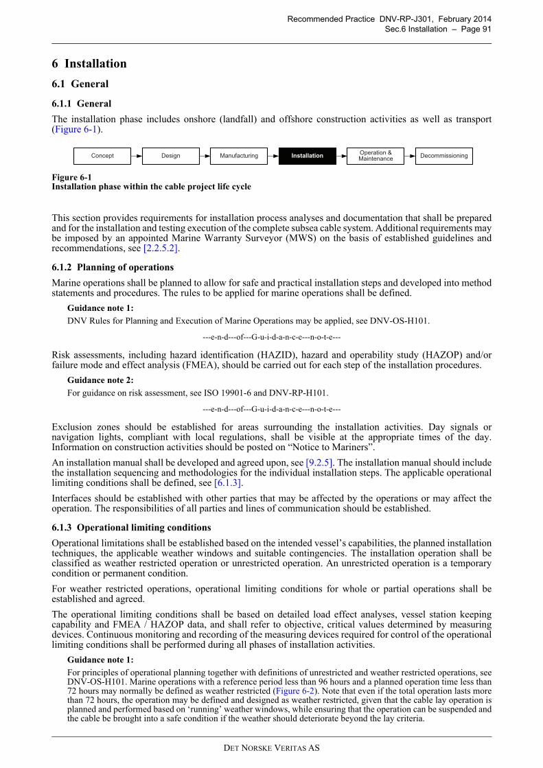
Recommended Practice DNV-RP-J301, February 2014
Sec.6 Installation – Page 91
6 Installation
6.1 General
6.1.1 General
The installation phase includes onshore (landfall) and offshore construction activities as well as transport(Figure 6-1).
Figure 6-1Installation phase within the cable project life cycle
This section provides requirements for installation process analyses and documentation that shall be preparedand for the installation and testing execution of the complete subsea cable system. Additional requirements maybe imposed by an appointed Marine Warranty Surveyor (MWS) on the basis of established guidelines andrecommendations, see [2.2.5.2].
6.1.2 Planning of operations
Marine operations shall be planned to allow for safe and practical installation steps and developed into methodstatements and procedures. The rules to be applied for marine operations shall be defined.
Guidance note 1:
DNV Rules for Planning and Execution of Marine Operations may be applied, see DNV-OS-H101.
---e-n-d---of---G-u-i-d-a-n-c-e---n-o-t-e---
Risk assessments, including hazard identification (HAZID), hazard and operability study (HAZOP) and/orfailure mode and effect analysis (FMEA), should be carried out for each step of the installation procedures.
Guidance note 2:
For guidance on risk assessment, see ISO 19901-6 and DNV-RP-H101.
---e-n-d---of---G-u-i-d-a-n-c-e---n-o-t-e---
Exclusion zones should be established for areas surrounding the installation activities. Day signals ornavigation lights, compliant with local regulations, shall be visible at the appropriate times of the day.Information on construction activities should be posted on “Notice to Mariners”.
An installation manual shall be developed and agreed upon, see [9.2.5]. The installation manual should includethe installation sequencing and methodologies for the individual installation steps. The applicable operationallimiting conditions shall be defined, see [6.1.3].
Interfaces should be established with other parties that may be affected by the operations or may affect theoperation. The responsibilities of all parties and lines of communication should be established.
6.1.3 Operational limiting conditions
Operational limitations shall be established based on the intended vessel’s capabilities, the planned installationtechniques, the applicable weather windows and suitable contingencies. The installation operation shall beclassified as weather restricted operation or unrestricted operation. An unrestricted operation is a temporarycondition or permanent condition.
For weather restricted operations, operational limiting conditions for whole or partial operations shall beestablished and agreed.
The operational limiting conditions shall be based on detailed load effect analyses, vessel station keepingcapability and FMEA / HAZOP data, and shall refer to objective, critical values determined by measuringdevices. Continuous monitoring and recording of the measuring devices required for control of the operationallimiting conditions shall be performed during all phases of installation activities.
Guidance note 1:
For principles of operational planning together with definitions of unrestricted and weather restricted operations, seeDNV-OS-H101. Marine operations with a reference period less than 96 hours and a planned operation time less than72 hours may normally be defined as weather restricted (Figure 6-2). Note that even if the total operation lasts morethan 72 hours, the operation may be defined and designed as weather restricted, given that the cable lay operation isplanned and performed based on ‘running’ weather windows, while ensuring that the operation can be suspended andthe cable be brought into a safe condition if the weather should deteriorate beyond the lay criteria.
DesignConceptOperation & Maintenance
Installation DecommissioningManufacturing
DET NORSKE VERITAS AS
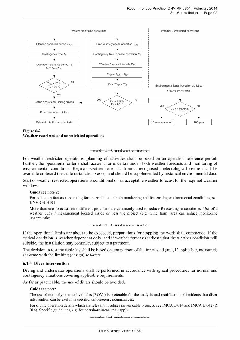
Recommended Practice DNV-RP-J301, February 2014
Sec.6 Installation – Page 92
Figure 6-2
Weather restricted and unrestricted operations
---e-n-d---of---G-u-i-d-a-n-c-e---n-o-t-e---
For weather restricted operations, planning of activities shall be based on an operation reference period.Further, the operational criteria shall account for uncertainties in both weather forecasts and monitoring ofenvironmental conditions. Regular weather forecasts from a recognised meteorological centre shall beavailable on-board the cable installation vessel, and should be supplemented by historical environmental data.
Start of weather restricted operations is conditional on an acceptable weather forecast for the required weatherwindow.
Guidance note 2:
For reduction factors accounting for uncertainties in both monitoring and forecasting environmental conditions, seeDNV-OS-H101.
More than one forecast from different providers are commonly used to reduce forecasting uncertainties. Use of aweather buoy / measurement located inside or near the project (e.g. wind farm) area can reduce monitoringuncertainties.
---e-n-d---of---G-u-i-d-a-n-c-e---n-o-t-e---
If the operational limits are about to be exceeded, preparations for stopping the work shall commence. If thecritical condition is weather dependent only, and if weather forecasts indicate that the weather condition willsubside, the installation may continue, subject to agreement.
The decision to resume cable lay shall be based on comparison of the forecasted (and, if applicable, measured)sea-state with the limiting (design) sea-state.
6.1.4 Diver intervention
Diving and underwater operations shall be performed in accordance with agreed procedures for normal andcontingency situations covering applicable requirements.
As far as practicable, the use of divers should be avoided.
Guidance note:
The use of remotely operated vehicles (ROVs) is preferable for the analysis and rectification of incidents, but diverintervention can be useful in specific, unforeseen circumstances.
For diving operation details which are relevant in subsea power cable projects, see IMCA D 014 and IMCA D 042 (R016). Specific guidelines, e.g. for nearshore areas, may apply.
---e-n-d---of---G-u-i-d-a-n-c-e---n-o-t-e---
Planned operation period TPOP
yes
TPOP < 72 h,
TR < 96 h?
no
Contingency time TC
Operation reference period TR
TR = TPOP + TC
Define operational limiting criteria
Determine uncertainties
Calculate start/interrupt criteria
Time to safely cease operation TSafe
Contingency time to cease operation T’C
Weather forecast intervals TWF
T’POP = TSafe + TWF
T’R = T’POP + T’C
T’POP < 72 h,
T’R < 96 h?
TR < 6 months?
10 year seasonal 100 year
Weather restricted operations Weather unrestricted operations
Environmental loads based on statistics
yes no
noyes
Figures by example
DET NORSKE VERITAS AS
Recommended Practice DNV-RP-J301, February 2014
Sec.6 Installation – Page 93
6.2 Installation spread
6.2.1 General
6.2.1.1 Qualification of vessel and equipment
All vessels and equipment planned for cable installation shall be qualified to perform work and supportingoperations within the determined operational limits.
Guidance note:
For vessel classification requirements, see [6.2.2]. Requalification is required if significant modification or alternationto the vessel, equipment or software has been made.
---e-n-d---of---G-u-i-d-a-n-c-e---n-o-t-e---
Qualification should be
— done according to a qualification plan— based on a systematic review of the specified operational limits for the selected vessel and equipment— reviewed through a combination of desk-based assessments (e.g. HAZID, HAZOP, FMEA), analyses,
simulations and tests— documented for employer or Marine Warranty Surveyor review.
Vessels, cable handling / installation equipment and associated (e.g. survey / ROV) systems shall have adocumented inspection and maintenance programme covering all systems vital for the safety and operationalperformance of the vessel, related to the operation to be performed. The maintenance programme shall beoutlined in an operation and maintenance manual or similar document.
6.2.1.2 Personnel
The organisation of key personnel with defined responsibilities and lines of communication shall be establishedprior to start of the operations. Interfaces with other parties shall be defined.All personnel shall be competent for their assigned work. Key personnel shall have sufficient verbalcommunication skills in the common language used during operations.For marine crews the manning levels should comply with IMO Res. A.1047 (27) - Principles of minimum safemanning. Non-propelled vessels should have similar manning and organisation as required for propelled unitsof a comparable type and size.For installation crews the staff levels should be adequate to execute the planned work in a safe manner.
6.2.2 Cable installation vessels
Vessels shall meet statutory requirements and in general have a valid class certificate with a recognisedclassification society or National Authorities. A vessel specification should state requirements for:
— general seaworthiness of the vessel for the region— anchoring systems, anchors, anchor lines and anchor winches— thrusters— positioning and survey equipment— dynamic positioning equipment and reference system— alarm systems, including remote alarms when required— cranes and lifting appliances— cable management and installation equipment— any other requirement due to the nature of the operations.
Guidance note:
Typical cable installation vessels can be distinguished into the following types:
— Shallow water barge capable of beaching, generally with anchor mooring positioning— Cable laying barge, with anchor mooring system or dynamic positioning— Cable laying vessel, with dynamic positioning.
Dependent on project scope and site conditions, more than one installation vessel type may be required. For instance,due to ultra-shallow draft requirements, nearshore construction activities may use purpose-built barges with lowerseaworthiness categorisation for installation works in favourable weather conditions.
---e-n-d---of---G-u-i-d-a-n-c-e---n-o-t-e---
Status reports for any recommendations or requirements given by National Authorities and/or classificationsocieties and the status of planned / completed maintenance shall be available for review by employer and/orMarine Warranty Surveyor.A vessel survey or inspection should, subject to agreement, be performed (typically by a Marine WarrantySurveyor) to confirm that the vessels and their principal equipment meet the specified requirements and aresuitable for the intended work, see also [4.3.2].
DET NORSKE VERITAS AS
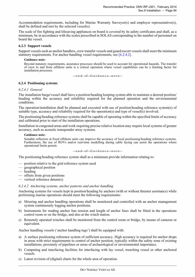
Recommended Practice DNV-RP-J301, February 2014
Sec.6 Installation – Page 94
Accommodation requirements, including for Marine Warranty Surveyor(s) and employer representative(s),shall be defined and met by the selected vessel(s).
The scale of fire fighting and lifesaving appliances on board is covered by its safety certificates and shall, as aminimum, be in accordance with the scales prescribed in SOLAS corresponding to the number of personnel onboard the vessel.
6.2.3 Support vessels
Support vessels such as anchor handlers, crew transfer vessels and guard/escort vessels shall meet the minimumstatutory requirements. For anchor handling vessel requirements, see [6.2.4.2].
Guidance note:
Beyond statutory requirements, assurance processes should be used to account for operational hazards. The transferof crew to and from offshore units is a critical operation where vessel capabilities can be a limiting factor forinstallation processes.
---e-n-d---of---G-u-i-d-a-n-c-e---n-o-t-e---
6.2.4 Positioning systems
6.2.4.1 General
The installation barge/vessel shall have a position/heading keeping system able to maintain a desired position/heading within the accuracy and reliability required for the planned operation and the environmentalconditions.
The operation/installation shall be planned and executed with use of position/heading reference system(s) ofsuitable type, accuracy and reliability required for the operation(s) and type of vessel(s) involved.
The positioning/heading reference systems shall be capable of operating within the specified limits of accuracyand calibrated prior to start of the installation operations.
Installation in congested areas and work requiring precise relative location may require local systems of greateraccuracy, such as acoustic transponder array systems.
Guidance note:
Suitable reflectors at fixed offshore units can improve the accuracy of local positioning/heading reference systems.Furthermore, the use of ROVs and/or real-time modelling during cable laying can assist the operations whereoperational limits permit.
---e-n-d---of---G-u-i-d-a-n-c-e---n-o-t-e---
The positioning/heading reference system shall as a minimum provide information relating to:
— position relative to the grid reference system used— geographical position— heading— offsets from given positions— vertical reference datum(s).
6.2.4.2 Anchoring systems, anchor patterns and anchor handling
Anchoring systems for vessels kept in position/heading by anchors (with or without thruster assistance) whileperforming marine operations should meet the following requirements:
a) Mooring and anchor handling operations shall be monitored and controlled with an anchor managementsystem continuously logging anchor positions.
b) Instruments for reading anchor line tension and length of anchor lines shall be fitted in the operationscontrol room or on the bridge, and also at the winch station.
c) Remotely operated winches shall be monitored from the control room or bridge, by means of cameras orequivalent.
Anchor handling vessels (‘anchor handling tugs’) shall be equipped with:
a) A surface positioning reference system of sufficient accuracy. High accuracy is required for anchor dropsin areas with strict requirements to control of anchor position, typically within the safety zone of existinginstallations, proximity of pipelines or areas of archaeological or environmental importance.
b) Computing and interfacing facilities for interfacing with lay vessel, trenching vessel or other anchoredvessels.
c) Latest revision of (digital) charts for the whole area of operation.
DET NORSKE VERITAS AS
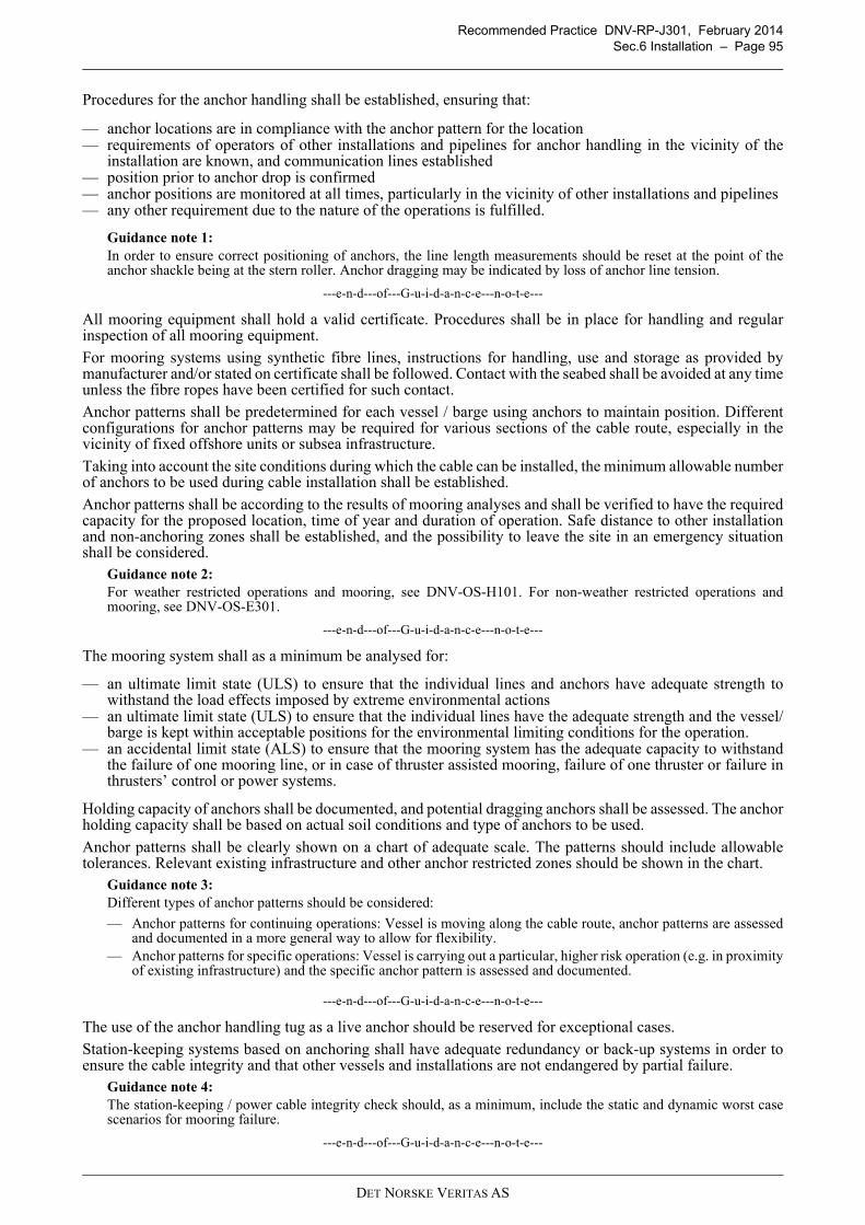
Recommended Practice DNV-RP-J301, February 2014
Sec.6 Installation – Page 95
Procedures for the anchor handling shall be established, ensuring that:
— anchor locations are in compliance with the anchor pattern for the location— requirements of operators of other installations and pipelines for anchor handling in the vicinity of the
installation are known, and communication lines established— position prior to anchor drop is confirmed— anchor positions are monitored at all times, particularly in the vicinity of other installations and pipelines— any other requirement due to the nature of the operations is fulfilled.
Guidance note 1:
In order to ensure correct positioning of anchors, the line length measurements should be reset at the point of theanchor shackle being at the stern roller. Anchor dragging may be indicated by loss of anchor line tension.
---e-n-d---of---G-u-i-d-a-n-c-e---n-o-t-e---
All mooring equipment shall hold a valid certificate. Procedures shall be in place for handling and regularinspection of all mooring equipment.
For mooring systems using synthetic fibre lines, instructions for handling, use and storage as provided bymanufacturer and/or stated on certificate shall be followed. Contact with the seabed shall be avoided at any timeunless the fibre ropes have been certified for such contact.
Anchor patterns shall be predetermined for each vessel / barge using anchors to maintain position. Differentconfigurations for anchor patterns may be required for various sections of the cable route, especially in thevicinity of fixed offshore units or subsea infrastructure.
Taking into account the site conditions during which the cable can be installed, the minimum allowable numberof anchors to be used during cable installation shall be established.
Anchor patterns shall be according to the results of mooring analyses and shall be verified to have the requiredcapacity for the proposed location, time of year and duration of operation. Safe distance to other installationand non-anchoring zones shall be established, and the possibility to leave the site in an emergency situationshall be considered.
Guidance note 2:
For weather restricted operations and mooring, see DNV-OS-H101. For non-weather restricted operations andmooring, see DNV-OS-E301.
---e-n-d---of---G-u-i-d-a-n-c-e---n-o-t-e---
The mooring system shall as a minimum be analysed for:
— an ultimate limit state (ULS) to ensure that the individual lines and anchors have adequate strength towithstand the load effects imposed by extreme environmental actions
— an ultimate limit state (ULS) to ensure that the individual lines have the adequate strength and the vessel/barge is kept within acceptable positions for the environmental limiting conditions for the operation.
— an accidental limit state (ALS) to ensure that the mooring system has the adequate capacity to withstandthe failure of one mooring line, or in case of thruster assisted mooring, failure of one thruster or failure inthrusters’ control or power systems.
Holding capacity of anchors shall be documented, and potential dragging anchors shall be assessed. The anchorholding capacity shall be based on actual soil conditions and type of anchors to be used.
Anchor patterns shall be clearly shown on a chart of adequate scale. The patterns should include allowabletolerances. Relevant existing infrastructure and other anchor restricted zones should be shown in the chart.
Guidance note 3:
Different types of anchor patterns should be considered:
— Anchor patterns for continuing operations: Vessel is moving along the cable route, anchor patterns are assessedand documented in a more general way to allow for flexibility.
— Anchor patterns for specific operations: Vessel is carrying out a particular, higher risk operation (e.g. in proximityof existing infrastructure) and the specific anchor pattern is assessed and documented.
---e-n-d---of---G-u-i-d-a-n-c-e---n-o-t-e---
The use of the anchor handling tug as a live anchor should be reserved for exceptional cases.
Station-keeping systems based on anchoring shall have adequate redundancy or back-up systems in order toensure the cable integrity and that other vessels and installations are not endangered by partial failure.
Guidance note 4:
The station-keeping / power cable integrity check should, as a minimum, include the static and dynamic worst casescenarios for mooring failure.
---e-n-d---of---G-u-i-d-a-n-c-e---n-o-t-e---
DET NORSKE VERITAS AS
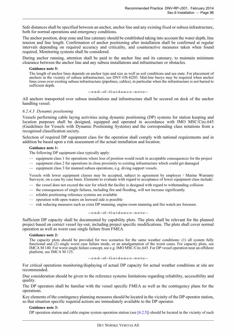
Recommended Practice DNV-RP-J301, February 2014
Sec.6 Installation – Page 96
Safe distances shall be specified between an anchor, anchor line and any existing fixed or subsea infrastructure,both for normal operations and emergency conditions.
The anchor position, drop zone and line catenary should be established taking into account the water depth, linetension and line length. Confirmation of anchor positioning after installation shall be confirmed at regularintervals depending on required accuracy and criticality, and counteractive measures taken when foundrequired. Monitoring systems shall be considered.
During anchor running, attention shall be paid to the anchor line and its catenary, to maintain minimumclearance between the anchor line and any subsea installations and infrastructure or obstacles.
Guidance note 5:
The length of anchor lines depends on anchor type and size as well as soil conditions and sea state. For placement ofanchors in the vicinity of subsea infrastructure, see DNV-OS-H203. Mid-line buoys may be required when anchorlines cross over existing subsea infrastructure (pipelines, cables), in particular when the infrastructure is not buried tosufficient depth.
---e-n-d---of---G-u-i-d-a-n-c-e---n-o-t-e---
All anchors transported over subsea installations and infrastructure shall be secured on deck of the anchorhandling vessel.
6.2.4.3 Dynamic positioning
Vessels performing cable laying activities using dynamic positioning (DP) systems for station keeping andlocation purposes shall be designed, equipped and operated in accordance with IMO MSC/Circ.645(Guidelines for Vessels with Dynamic Positioning Systems) and the corresponding class notations from arecognised classification society.
Selection of required DP equipment class for the operation shall comply with national requirements and inaddition be based upon a risk assessment of the actual installation and location.
Guidance note 1:
The following DP equipment class typically apply:
— equipment class 1 for operations where loss of position would result in acceptable consequences for the project— equipment class 2 for operations in close proximity to existing infrastructure which could get damaged— equipment class 3 for manned subsea operations, e.g. diving support vessels.
Vessels with lower equipment classes may be accepted, subject to agreement by employer / Marine WarrantySurveyor, on a case by case basis. Elements to evaluate with regard to acceptance of lower equipment class include:
— the vessel does not exceed the size for which the facility is designed with regard to withstanding collision— the consequences of single failures, including fire and flooding, will not increase significantly— reliable positioning reference systems are available— operation with open waters on leeward side is possible— risk reducing measures such as extra DP manning, engine room manning and fire watch are foreseen.
---e-n-d---of---G-u-i-d-a-n-c-e---n-o-t-e---
Sufficient DP capacity shall be documented by capability plots. The plots shall be relevant for the plannedproject based on correct vessel lay-out, including project specific modifications. The plots shall cover normaloperation as well as worst case single failure from FMEA.
Guidance note 2:
The capacity plots should be provided for two scenarios for the same weather conditions: (1) all system fullyfunctional and (2) single worst case failure mode, or an amalgamation of the worst cases. For capacity plots, seeIMCA M 140. For worst single failure concept, see e.g. IMO MSC/Circ.645. For DP vessel operation near an offshoreplatform, see IMCA M 125.
---e-n-d---of---G-u-i-d-a-n-c-e---n-o-t-e---
For critical operations monitoring/displaying of actual DP capacity for actual weather conditions at site arerecommended.
Due consideration should be given to the reference systems limitations regarding reliability, accessibility andquality.The DP operators shall be familiar with the vessel specific FMEA as well as the contingency plans for theoperations.
Key elements of the contingency planning measures should be located in the vicinity of the DP operator station,so that situation specific required actions are immediately available to the DP operator.
Guidance note 3:
DP operation station and cable engine system operation station (see [6.2.5]) should be located in the vicinity of each
DET NORSKE VERITAS AS
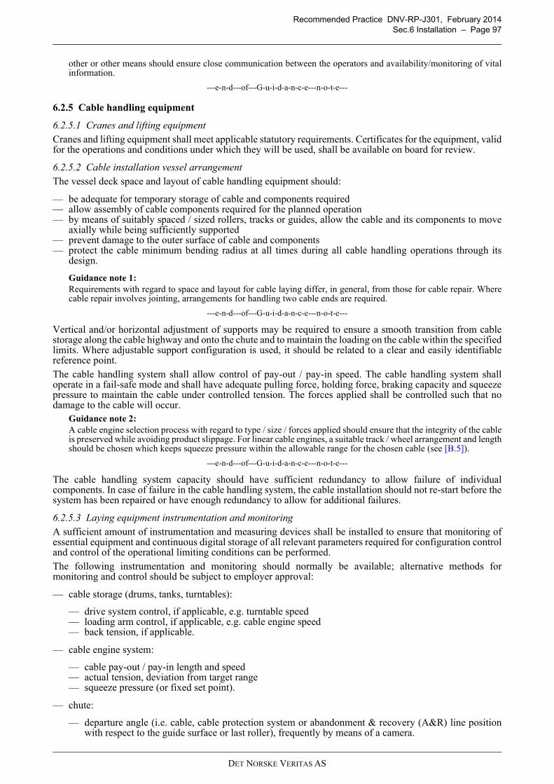
Recommended Practice DNV-RP-J301, February 2014
Sec.6 Installation – Page 97
other or other means should ensure close communication between the operators and availability/monitoring of vitalinformation.
---e-n-d---of---G-u-i-d-a-n-c-e---n-o-t-e---
6.2.5 Cable handling equipment
6.2.5.1 Cranes and lifting equipment
Cranes and lifting equipment shall meet applicable statutory requirements. Certificates for the equipment, validfor the operations and conditions under which they will be used, shall be available on board for review.
6.2.5.2 Cable installation vessel arrangement
The vessel deck space and layout of cable handling equipment should:
— be adequate for temporary storage of cable and components required— allow assembly of cable components required for the planned operation— by means of suitably spaced / sized rollers, tracks or guides, allow the cable and its components to move
axially while being sufficiently supported— prevent damage to the outer surface of cable and components— protect the cable minimum bending radius at all times during all cable handling operations through its
design.
Guidance note 1:
Requirements with regard to space and layout for cable laying differ, in general, from those for cable repair. Wherecable repair involves jointing, arrangements for handling two cable ends are required.
---e-n-d---of---G-u-i-d-a-n-c-e---n-o-t-e---
Vertical and/or horizontal adjustment of supports may be required to ensure a smooth transition from cablestorage along the cable highway and onto the chute and to maintain the loading on the cable within the specifiedlimits. Where adjustable support configuration is used, it should be related to a clear and easily identifiablereference point.
The cable handling system shall allow control of pay-out / pay-in speed. The cable handling system shalloperate in a fail-safe mode and shall have adequate pulling force, holding force, braking capacity and squeezepressure to maintain the cable under controlled tension. The forces applied shall be controlled such that nodamage to the cable will occur.
Guidance note 2:
A cable engine selection process with regard to type / size / forces applied should ensure that the integrity of the cableis preserved while avoiding product slippage. For linear cable engines, a suitable track / wheel arrangement and lengthshould be chosen which keeps squeeze pressure within the allowable range for the chosen cable (see [B.5]).
---e-n-d---of---G-u-i-d-a-n-c-e---n-o-t-e---
The cable handling system capacity should have sufficient redundancy to allow failure of individualcomponents. In case of failure in the cable handling system, the cable installation should not re-start before thesystem has been repaired or have enough redundancy to allow for additional failures.
6.2.5.3 Laying equipment instrumentation and monitoring
A sufficient amount of instrumentation and measuring devices shall be installed to ensure that monitoring ofessential equipment and continuous digital storage of all relevant parameters required for configuration controland control of the operational limiting conditions can be performed.
The following instrumentation and monitoring should normally be available; alternative methods formonitoring and control should be subject to employer approval:
— cable storage (drums, tanks, turntables):
— drive system control, if applicable, e.g. turntable speed— loading arm control, if applicable, e.g. cable engine speed— back tension, if applicable.
— cable engine system:
— cable pay-out / pay-in length and speed— actual tension, deviation from target range— squeeze pressure (or fixed set point).
— chute:
— departure angle (i.e. cable, cable protection system or abandonment & recovery (A&R) line positionwith respect to the guide surface or last roller), frequently by means of a camera.
DET NORSKE VERITAS AS
Recommended Practice DNV-RP-J301, February 2014
Sec.6 Installation – Page 98
— lay configuration:
— lay parameter monitoring and recording as applicable to the installation method, including independenttension monitoring if required
— touch down monitoring with appropriate systems capable of operating under the expected operationalweather conditions at the times / locations required
— communication between devices.
— winches:
— line tension and length recorder for A&R system— requirements in [6.2.4.2] for anchor winches.
— vessel:
— vessel position— vessel movements such as roll, pitch, sway, heave— water depth— vessel draught and trim— wind speed and direction.
The functioning of essential measuring devices should be verified at regular intervals. Direct reading andprocessing of stored records from all required essential instrumentation and measuring devices shouldpreferably be possible at the vessel’s bridge.
Guidance note:
Lay monitoring and control may also use real-time cable modelling software, taking input from vessel position, cableengine and marine conditions and calculating / controlling cable catenary. Preferably the departure of the cableoverboard can be monitored by video recording during cable installation.
---e-n-d---of---G-u-i-d-a-n-c-e---n-o-t-e---
All measuring equipment used should be provided with an adequate amount of spares to ensure smoothoperation.
6.2.5.4 Calibration and testing
All measuring equipment shall be calibrated in accordance with its manufacturer’s recommendations andadequate documentation of calibration shall be available on-board the vessel prior to start of work and duringthe whole operation.
Essential equipment shall be calibrated against a certified load cell. If essential components for the equipmentsuch as load cells, amplifiers or software are replaced or modified the equipment shall be tested and re-calibrated. Indications of equipment out of calibration should trigger a re-calibration. The certified load cellused for calibration shall have a certificate from a recognised certification body which is not older than oneyear.
Guidance note 1:
Typical essential equipment can be, but are not limited to, cable engines, clamps, winches, cranes and liftingequipment, positioning systems.
---e-n-d---of---G-u-i-d-a-n-c-e---n-o-t-e---
Testing and calibration shall be done according to the test procedures. Test procedures shall be subject toagreement. The test procedures shall provide documented acceptance criteria for the testing and calibration.The acceptance criteria shall be evaluated and set according to the cable integrity. Any deviation from thecorrect value shall be accounted for.
Calibration and testing should be planned and performed such that it can be witnessed.
During testing and calibration the complete load range should be covered. For linear trends at least five loadsteps should be applied up to maximum expected dynamic loads, more steps are required when testing tomaximum capacity. Non-linear trends require higher numbers of load steps. Cyclic loading should beconsidered.
Guidance note 2:
Cable engine system testing includes combinations of cable engine(s), clamp(s) and cable storage, and testing ofsingle cable engine failure when running more than one cable engine, test redundancy of single cable engines, fail safeactions, loss of main power and loss of signal.
---e-n-d---of---G-u-i-d-a-n-c-e---n-o-t-e---
The calibration and testing of essential equipment should as a minimum be performed on an annual basis.
DET NORSKE VERITAS AS
Recommended Practice DNV-RP-J301, February 2014
Sec.6 Installation – Page 99
For each specific project, testing and documentation of vessels and equipment shall as a minimum include:
— in-field dynamic positioning system test (DP acceptance test)— maintenance and calibration records of critical/essential equipment, including testing equipment— maintenance and calibration records of critical/essential equipment on support vessels— pull and fail safe test of the cable holding system to verify sufficient squeeze pressure and friction— A&R test.
A modification should be evaluated and documented regarding its potential to invalidate calibration. Re-testingshould normally be performed in the following cases:
— if the annual testing was performed with a different setup (e.g. different clamps or pads or cable diameter)— after equipment has been maintained in a way that affects calibration— when equipment is exchanged or significantly modified.
6.2.6 Mobilisation
Before mobilisation, procedures for safe operations shall be in place.
In accordance with the mobilisation manual, all equipment needed for the operation shall be mobilised.
During mobilisation,
— the vessel spread is fitted with all equipment necessary for the intended activity / operation— the equipment is checked, serviced and adjusted and necessary tests / calibrations are carried out— seafastening of equipment and, after load-out, cable / components is carried out.
On the cable installation vessel, the cable path / highway should be adjusted to the correct configuration. Ifadjustable, the cable supports and/or chute should be verified.
Handling and storage of cables and materials on supply, laying and support vessels shall ensure that hazards topersonnel, cable and accessories are avoided. Slings and other equipment used shall be designed to preventdamage of the handled products. Equipment and material (permanent and temporary) shall be controlled andrecords maintained. For temporary storage and transport of cable, see also [5.3].
All equipment, cables, accessories, consumables, etc. shall be seafastened to withstand transportation loadswithin the operational limits expected for the location (sea voyage, project area) and time of the operation.
Trim and ballasting shall be verified to be according to procedures prior to start of operations.
All personnel shall be familiarised with the operations to be performed. Personnel involved in criticaloperations should participate in a risk assessment, safe job analysis and/or toolbox talk ensuring that risksinvolved in the operation are understood.
6.2.7 Cable burial equipment
6.2.7.1 Equipment characteristics
A diverse range of cable laying and burial equipment with differing capabilities can be used in the cableinstallation process. The selection of equipment best suited for the task is an iterative process involving thefollowing review steps which may lead to different solutions for array and export cables:
a) Seabed conditions: Consideration of general feasibility of cable burial, achievable burial depth and suitableburial method.Guidance note 1:
Figure 6-3 indicates potential burial techniques depending on ground conditions. Scales for cohesive and cohesionlesssoils are mapped approximately onto the x-axis. The suitability of the tools is shown on the y-axis. Ploughing (solidline) is suitable for a wide range of ground conditions. Jetting (dashed line) is suitable for soft or loose soils.Mechanical cutting (dash-dot line) is suitable for hard or dense soils. The boundaries are indicative only withequipment options widening the range of application. Fibrous material such as peat can be challenging for any burialtechnique.
DET NORSKE VERITAS AS
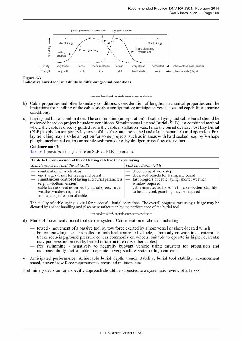
Recommended Practice DNV-RP-J301, February 2014
Sec.6 Installation – Page 100
Figure 6-3Indicative burial tool suitability in different ground conditions
---e-n-d---of---G-u-i-d-a-n-c-e---n-o-t-e---
b) Cable properties and other boundary conditions: Consideration of lengths, mechanical properties and thelimitations for handling of the cable or cable configuration; anticipated vessel size and capabilities; marineconditions.
c) Laying and burial combination: The combination (or separation) of cable laying and cable burial should bereviewed based on project boundary conditions. Simultaneous Lay and Burial (SLB) is a combined methodwhere the cable is directly guided from the cable installation vessel into the burial device. Post Lay Burial(PLB) involves a temporary laydown of the cable onto the seabed and a later, separate burial operation. Pre-lay trenching may also be an option for some projects, such as in areas with hard seabed (e.g. by V-shapeplough, mechanical cutter) or mobile sediments (e.g. by dredger, mass flow excavator).Guidance note 2:
Table 6-1 provides some guidance on SLB vs. PLB approaches.
The quality of cable laying is vital for successful burial operations. The overall progress rate using a barge may bedictated by anchor handling and placement rather than by the performance of the burial tool.
---e-n-d---of---G-u-i-d-a-n-c-e---n-o-t-e---
d) Mode of movement / burial tool carrier system: Consideration of choices including:
— towed - movement of a passive tool by tow force exerted by a host vessel or shore-located winch— bottom crawling - self-propelled or umbilical controlled vehicle, commonly on wide-track caterpillar
tracks reducing ground pressure or less commonly on wheels; suitable to operate in higher currents;may put pressure on nearby buried infrastructure (e.g. other cables)
— free swimming - negatively to neutrally buoyant vehicle using thrusters for propulsion andmanoeuvrability; not suitable to operate in very shallow water or high currents.
e) Anticipated performance: Achievable burial depth, trench stability, burial tool stability, advancementspeed, power / tow force requirements, wear and maintenance.
Preliminary decision for a specific approach should be subjected to a systematic review of all risks.
Table 6-1 Comparison of burial timing relative to cable laying
Simultaneous Lay and Burial (SLB) Post Lay Burial (PLB)
— combination of work steps— one (large) vessel for laying and burial— simultaneous control of laying and burial parameters
(e.g. on-bottom tension)— cable laying speed governed by burial speed, large
weather window required— immediate protection of cable
— decoupling of work steps— dedicated vessels for laying and burial— fast progress of cable laying, shorter weather
window required— cable unprotected for some time, on-bottom stability
to be analysed, guarding may be required
P l o u g h i n g
very loose loose medium dense dense very dense cementedDensity:
Strength: very soft soft firm stiff hard, chalk rock
J e t t i n g C u t t i n g
share vibration,
rock ripping S
uita
bili
ty
jetting parameter optimisation
jetting
support
dredging system
cohesive soils (clays)
cohesionless soils (sands)
DET NORSKE VERITAS AS
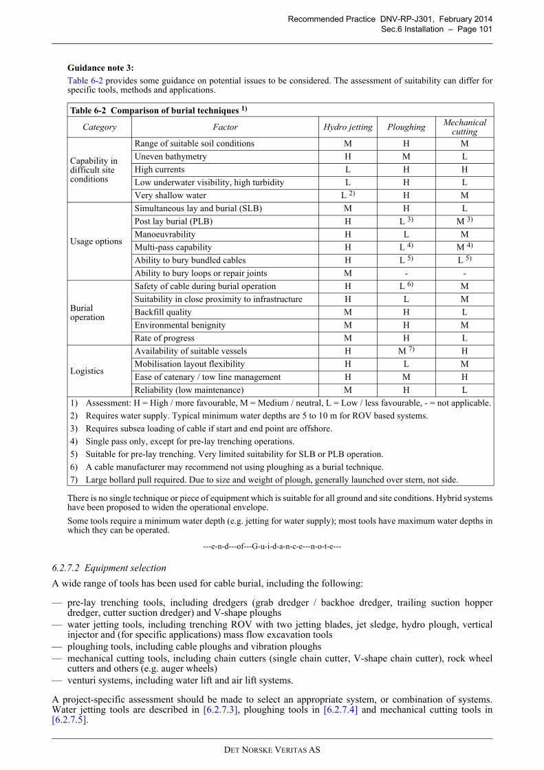
Recommended Practice DNV-RP-J301, February 2014
Sec.6 Installation – Page 101
Guidance note 3:
Table 6-2 provides some guidance on potential issues to be considered. The assessment of suitability can differ forspecific tools, methods and applications.
There is no single technique or piece of equipment which is suitable for all ground and site conditions. Hybrid systemshave been proposed to widen the operational envelope.
Some tools require a minimum water depth (e.g. jetting for water supply); most tools have maximum water depths inwhich they can be operated.
---e-n-d---of---G-u-i-d-a-n-c-e---n-o-t-e---
6.2.7.2 Equipment selection
A wide range of tools has been used for cable burial, including the following:
— pre-lay trenching tools, including dredgers (grab dredger / backhoe dredger, trailing suction hopperdredger, cutter suction dredger) and V-shape ploughs
— water jetting tools, including trenching ROV with two jetting blades, jet sledge, hydro plough, verticalinjector and (for specific applications) mass flow excavation tools
— ploughing tools, including cable ploughs and vibration ploughs— mechanical cutting tools, including chain cutters (single chain cutter, V-shape chain cutter), rock wheel
cutters and others (e.g. auger wheels)— venturi systems, including water lift and air lift systems.
A project-specific assessment should be made to select an appropriate system, or combination of systems.Water jetting tools are described in [6.2.7.3], ploughing tools in [6.2.7.4] and mechanical cutting tools in[6.2.7.5].
Table 6-2 Comparison of burial techniques 1)
Category Factor Hydro jetting PloughingMechanical
cutting
Capability in difficult site conditions
Range of suitable soil conditions M H M
Uneven bathymetry H M L
High currents L H H
Low underwater visibility, high turbidity L H L
Very shallow water L 2) H M
Usage options
Simultaneous lay and burial (SLB) M H L
Post lay burial (PLB) H L 3) M 3)
Manoeuvrability H L M
Multi-pass capability H L 4) M 4)
Ability to bury bundled cables H L 5) L 5)
Ability to bury loops or repair joints M - -
Burial operation
Safety of cable during burial operation H L 6) M
Suitability in close proximity to infrastructure H L M
Backfill quality M H L
Environmental benignity M H M
Rate of progress M H L
Logistics
Availability of suitable vessels H M 7) H
Mobilisation layout flexibility H L M
Ease of catenary / tow line management H M H
Reliability (low maintenance) M H L
1) Assessment: H = High / more favourable, M = Medium / neutral, L = Low / less favourable, - = not applicable.
2) Requires water supply. Typical minimum water depths are 5 to 10 m for ROV based systems.
3) Requires subsea loading of cable if start and end point are offshore.
4) Single pass only, except for pre-lay trenching operations.
5) Suitable for pre-lay trenching. Very limited suitability for SLB or PLB operation.
6) A cable manufacturer may recommend not using ploughing as a burial technique.
7) Large bollard pull required. Due to size and weight of plough, generally launched over stern, not side.
DET NORSKE VERITAS AS
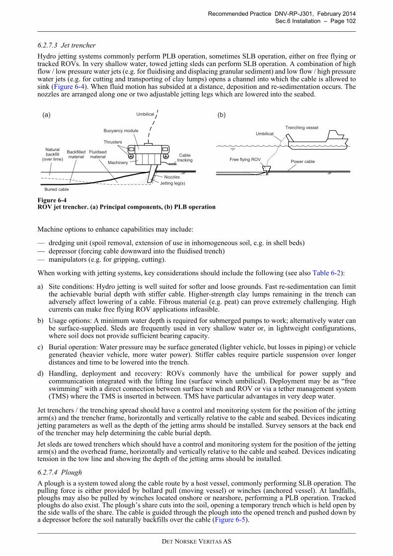
Recommended Practice DNV-RP-J301, February 2014
Sec.6 Installation – Page 102
6.2.7.3 Jet trencher
Hydro jetting systems commonly perform PLB operation, sometimes SLB operation, either on free flying ortracked ROVs. In very shallow water, towed jetting sleds can perform SLB operation. A combination of highflow / low pressure water jets (e.g. for fluidising and displacing granular sediment) and low flow / high pressurewater jets (e.g. for cutting and transporting of clay lumps) opens a channel into which the cable is allowed tosink (Figure 6-4). When fluid motion has subsided at a distance, deposition and re-sedimentation occurs. Thenozzles are arranged along one or two adjustable jetting legs which are lowered into the seabed.
Figure 6-4ROV jet trencher. (a) Principal components, (b) PLB operation
Machine options to enhance capabilities may include:
— dredging unit (spoil removal, extension of use in inhomogeneous soil, e.g. in shell beds)— depressor (forcing cable downward into the fluidised trench)— manipulators (e.g. for gripping, cutting).
When working with jetting systems, key considerations should include the following (see also Table 6-2):
a) Site conditions: Hydro jetting is well suited for softer and loose grounds. Fast re-sedimentation can limitthe achievable burial depth with stiffer cable. Higher-strength clay lumps remaining in the trench canadversely affect lowering of a cable. Fibrous material (e.g. peat) can prove extremely challenging. Highcurrents can make free flying ROV applications infeasible.
b) Usage options: A minimum water depth is required for submerged pumps to work; alternatively water canbe surface-supplied. Sleds are frequently used in very shallow water or, in lightweight configurations,where soil does not provide sufficient bearing capacity.
c) Burial operation: Water pressure may be surface generated (lighter vehicle, but losses in piping) or vehiclegenerated (heavier vehicle, more water power). Stiffer cables require particle suspension over longerdistances and time to be lowered into the trench.
d) Handling, deployment and recovery: ROVs commonly have the umbilical for power supply andcommunication integrated with the lifting line (surface winch umbilical). Deployment may be as “freeswimming” with a direct connection between surface winch and ROV or via a tether management system(TMS) where the TMS is inserted in between. TMS have particular advantages in very deep water.
Jet trenchers / the trenching spread should have a control and monitoring system for the position of the jettingarm(s) and the trencher frame, horizontally and vertically relative to the cable and seabed. Devices indicatingjetting parameters as well as the depth of the jetting arms should be installed. Survey sensors at the back endof the trencher may help determining the cable burial depth.
Jet sleds are towed trenchers which should have a control and monitoring system for the position of the jettingarm(s) and the overhead frame, horizontally and vertically relative to the cable and seabed. Devices indicatingtension in the tow line and showing the depth of the jetting arms should be installed.
6.2.7.4 Plough
A plough is a system towed along the cable route by a host vessel, commonly performing SLB operation. Thepulling force is either provided by bollard pull (moving vessel) or winches (anchored vessel). At landfalls,ploughs may also be pulled by winches located onshore or nearshore, performing a PLB operation. Trackedploughs do also exist. The plough’s share cuts into the soil, opening a temporary trench which is held open bythe side walls of the share. The cable is guided through the plough into the opened trench and pushed down bya depressor before the soil naturally backfills over the cable (Figure 6-5).
(a) (b)
Trenching vessel
Umbilical
Buried cable
Backfilledmaterial
Fluidisedmaterial
Nozzles
Jetting leg(s)
Buoyancy module
Thrusters
Machinery
Cabletracking
Umbilical
Free flying ROV
Naturalbackfill
(over time)Power cable
DET NORSKE VERITAS AS
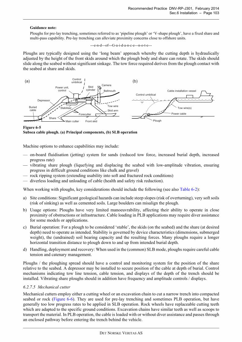
Recommended Practice DNV-RP-J301, February 2014
Sec.6 Installation – Page 103
6.5
Guidance note:
Ploughs for pre-lay trenching, sometimes referred to as ‘pipeline plough’ or ‘V-shape plough’, have a fixed share andmulti-pass capability. Pre-lay trenching can alleviate proximity concerns close to offshore units.
---e-n-d---of---G-u-i-d-a-n-c-e---n-o-t-e---
Ploughs are typically designed using the ‘long beam’ approach whereby the cutting depth is hydraulicallyadjusted by the height of the front skids around which the plough body and share can rotate. The skids shouldslide along the seabed without significant sinkage. The tow force required derives from the plough contact withthe seabed at share and skids.
Figure 6-5
Subsea cable plough. (a) Principal components, (b) SLB operation
Machine options to enhance capabilities may include:
— on-board fluidisation (jetting) system for sands (reduced tow force, increased burial depth, increasedprogress rate)
— vibrating share plough (liquefying and displacing the seabed with low-amplitude vibration, ensuringprogress in difficult ground conditions like chalk and gravel)
— rock ripping system (extending usability into soft and fractured rock conditions)— diverless loading and unloading of cable (health and safety risk reduction).
When working with ploughs, key considerations should include the following (see also Table 6-2):
a) Site conditions: Significant geological hazards can include steep slopes (risk of overturning), very soft soils(risk of sinking) as well as cemented soils. Large boulders can misalign the plough.
b) Usage options: Ploughs have very limited manoeuvrability, affecting their ability to operate in closeproximity of obstructions or infrastructure. Cable loading in PLB applications may require diver assistancefor some models or applications.
c) Burial operation: For a plough to be considered ‘stable’, the skids (on the seabed) and the share (at desireddepth) need to operate as intended. Stability is governed by device characteristics (dimensions, submergedweight), the (undrained) soil bearing capacity and the resulting forces. Many ploughs require a longerhorizontal transition distance to plough down to and up from intended burial depth.
d) Handling, deployment and recovery: When used in the (common) SLB mode, ploughs require careful cabletension and catenary management.
Ploughs / the ploughing spread should have a control and monitoring system for the position of the sharerelative to the seabed. A depressor may be installed to secure position of the cable at depth of burial. Controlmechanisms indicating tow line tension, cable tension, and displays of the depth of the trench should beinstalled. Vibrating share ploughs should in addition have frequency and amplitude controls / displays.
6.2.7.5 Mechanical cutter
Mechanical cutters employ either a cutting wheel or an excavation chain to cut a narrow trench into compactedseabed or rock (Figure 6-6). They are used for pre-lay trenching and sometimes PLB operation, but havegenerally too low progress rates to be applied in SLB operation. Rock wheels have replaceable cutting teethwhich are adapted to the specific ground conditions. Excavation chains have similar teeth as well as scoops totransport the material. In PLB operation, the cable is loaded with or without diver assistance and passes throughan enclosed pathway before entering the trench behind the vehicle.
(a) (b)
Control umbilical
Power cable
Tow wire(s)
Cable installation vessel
Plough
Skid arm
Front skid
Bellmouth
CameraPower unit,
control
Forecutter
Main cutter
Share
Depressor
Stabiliser
Skidcylinder
Tow wire
Controlumbilical
Buried cable
DET NORSKE VERITAS AS
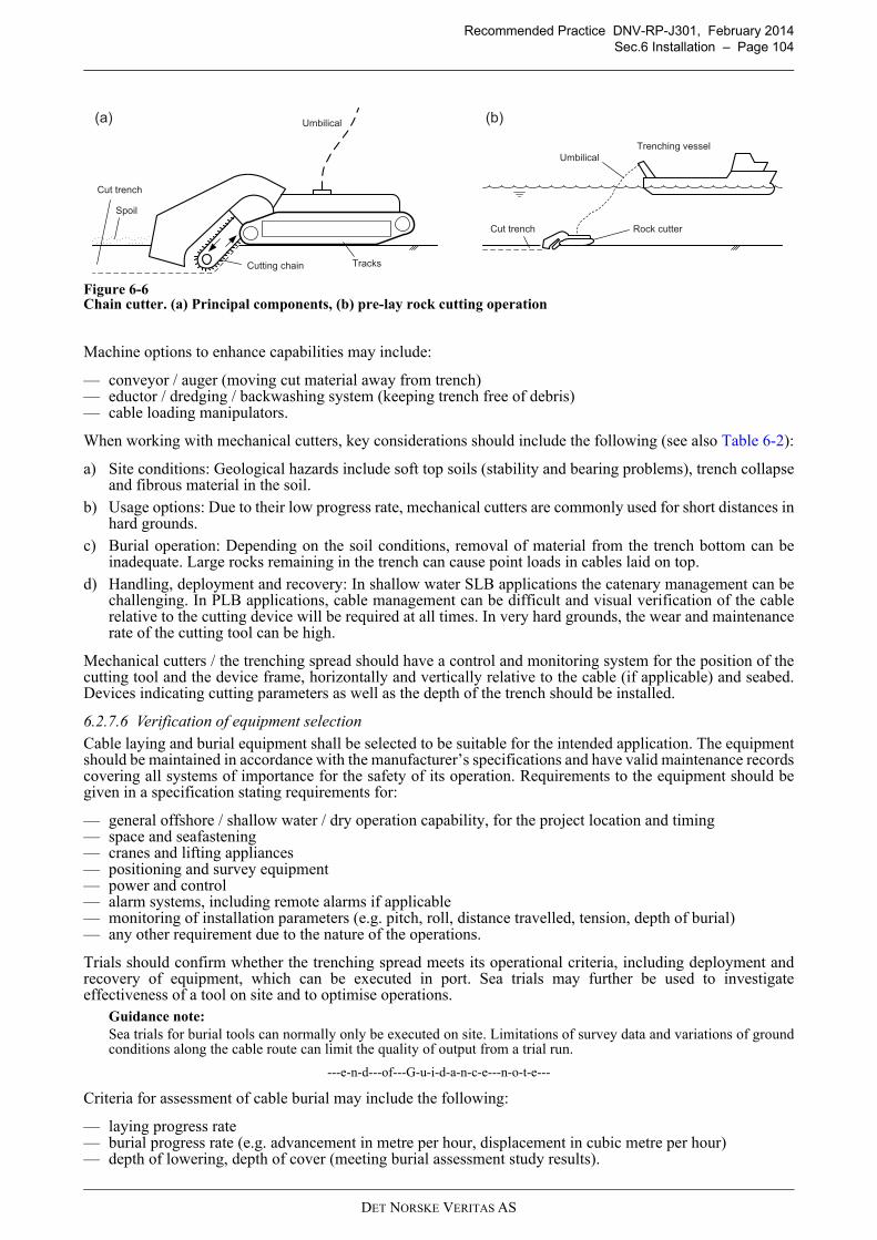
Recommended Practice DNV-RP-J301, February 2014
Sec.6 Installation – Page 104
Figure 6-6Chain cutter. (a) Principal components, (b) pre-lay rock cutting operation
Machine options to enhance capabilities may include:
— conveyor / auger (moving cut material away from trench)— eductor / dredging / backwashing system (keeping trench free of debris)— cable loading manipulators.
When working with mechanical cutters, key considerations should include the following (see also Table 6-2):
a) Site conditions: Geological hazards include soft top soils (stability and bearing problems), trench collapseand fibrous material in the soil.
b) Usage options: Due to their low progress rate, mechanical cutters are commonly used for short distances inhard grounds.
c) Burial operation: Depending on the soil conditions, removal of material from the trench bottom can beinadequate. Large rocks remaining in the trench can cause point loads in cables laid on top.
d) Handling, deployment and recovery: In shallow water SLB applications the catenary management can bechallenging. In PLB applications, cable management can be difficult and visual verification of the cablerelative to the cutting device will be required at all times. In very hard grounds, the wear and maintenancerate of the cutting tool can be high.
Mechanical cutters / the trenching spread should have a control and monitoring system for the position of thecutting tool and the device frame, horizontally and vertically relative to the cable (if applicable) and seabed.Devices indicating cutting parameters as well as the depth of the trench should be installed.
6.2.7.6 Verification of equipment selection
Cable laying and burial equipment shall be selected to be suitable for the intended application. The equipmentshould be maintained in accordance with the manufacturer’s specifications and have valid maintenance recordscovering all systems of importance for the safety of its operation. Requirements to the equipment should begiven in a specification stating requirements for:
— general offshore / shallow water / dry operation capability, for the project location and timing— space and seafastening— cranes and lifting appliances— positioning and survey equipment— power and control— alarm systems, including remote alarms if applicable— monitoring of installation parameters (e.g. pitch, roll, distance travelled, tension, depth of burial)— any other requirement due to the nature of the operations.
Trials should confirm whether the trenching spread meets its operational criteria, including deployment andrecovery of equipment, which can be executed in port. Sea trials may further be used to investigateeffectiveness of a tool on site and to optimise operations.
Guidance note:
Sea trials for burial tools can normally only be executed on site. Limitations of survey data and variations of groundconditions along the cable route can limit the quality of output from a trial run.
---e-n-d---of---G-u-i-d-a-n-c-e---n-o-t-e---
Criteria for assessment of cable burial may include the following:
— laying progress rate— burial progress rate (e.g. advancement in metre per hour, displacement in cubic metre per hour)— depth of lowering, depth of cover (meeting burial assessment study results).
(a) (b)
Trenching vessel
Umbilical
Cut trench
Spoil
Tracks
Umbilical
Rock cutterCut trench
Cutting chain
DET NORSKE VERITAS AS
Recommended Practice DNV-RP-J301, February 2014
Sec.6 Installation – Page 105
6.3 Pre-lay survey and route preparation
6.3.1 Pre-installation route survey
A pre-installation survey of the cable route should be performed in addition to the route survey required fordesign purposes covered in [3.4] if:
— the time elapsed since the previous survey is significant— seabed level changes are likely to have occurred— the route is in areas with heavy marine activity— new offshore infrastructure is present in the area and as-built information is not available— after the previous survey, seabed preparation work was performed close to the route— a significant deviation from the originally planned cable route occurred, outside the area previously
surveyed.
Where applicable, the extent of, and the requirements for, the pre-installation route survey shall be specified.The schedule of the survey should avoid interference with other on-site execution works.
Guidance note:
The pre-installation survey typically consists of a geophysical method which allows identifying hazards within thecable corridor. Visual (ROV) survey may be required to confirm specific features on the seabed.
---e-n-d---of---G-u-i-d-a-n-c-e---n-o-t-e---
The pre-installation survey should determine and/or verify:
— that the present seabed conditions match those of the survey required in [3.4]— potential new/previously not identified hazards to the cable and the installation operations.
Results of this survey should be reflected in the project execution plans.
6.3.2 Cable route preparation
Cable route clearance may be required to remove obstacles (on seabed surface, sub-surface) and potentialhazards interfering with the installation operations, for instance:
— boulders— debris affecting lay and burial operations— unexploded ordnance (UXO)— out-of-service cables.
Guidance note 1:
The width of the corridor to be cleared should be consistent with the risk profile of the route. Routing around objectslike boulders or suspected / identified UXO can be more cost effective than clearing. UXO clearance typically requiresinvolvement of authorities / special services. For considerations of removal of out-of-service telecommunicationcables, see ICPC Recommendation 1.
---e-n-d---of---G-u-i-d-a-n-c-e---n-o-t-e---
Cable route preparation may be required, for instance, to:
— prevent loads that occur as a result of seabed or shore area conditions (such as unstable slopes, sand waves,deep valleys, possible erosion and scour) from exceeding the cable system design criteria
— prepare for pipeline and cable crossings— infill depressions and remove high spots to prevent unacceptable free spans— dredge at cable entry points of offshore units, if sediment accretion/depletion is outside the design
envelope, e.g. clearing of J-tube entrances— excavate pre-lay trenches with a sufficiently smooth bottom profile— carry out any other preparation due to the nature of the succeeding operations.
Cable route clearance and cable route preparation should be carried out according to the specificationdeveloped during the design phase (see [4.5.1]). If applicable, these works should be recorded and documentedin a way adequate for as-built documentation (see [9.2.5]).
Cable route clearance and cable route preparation activities should be carried out well in advance of cable layand burial operations to accommodate for unexpected difficulties. Where unforeseen activities are required, arisk assessment should be conducted and the required approvals be obtained.
A pre-lay grapnel run (PLGR) should normally be carried out as near in time as practical prior to the cablelaying operation to assure a debris-free cable route. The potential for subsequent removal campaigns should beconsidered.
Guidance note 2:
Pre-lay grapnel operation can ensure that there are no recent physical obstructions. Physical obstructions may include
DET NORSKE VERITAS AS
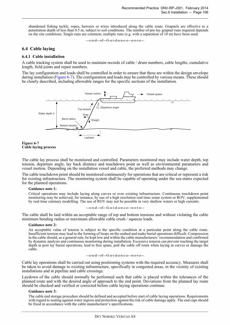
Recommended Practice DNV-RP-J301, February 2014
Sec.6 Installation – Page 106
abandoned fishing tackle, ropes, hawsers or wires introduced along the cable route. Grapnels are effective to apenetration depth of less than 0.5 m, subject to soil conditions. The number of pre-lay grapnel runs required dependson the site conditions. Single runs are common; multiple runs (e.g. with a separation of 10 m) have been used.
---e-n-d---of---G-u-i-d-a-n-c-e---n-o-t-e---
6.4 Cable laying
6.4.1 Cable installation
A cable tracking system shall be used to maintain records of cable / drum numbers, cable lengths, cumulativelength, field joints and repair numbers.
The lay configuration and loads shall be controlled in order to ensure that these are within the design envelopeduring installation (Figure 6-7). The configuration and loads may be controlled by various means. These shouldbe clearly described, including allowable ranges for the specific sections of the installation.
Figure 6-7Cable laying process
The cable lay process shall be monitored and controlled. Parameters monitored may include water depth, toptension, departure angle, lay back distance and touchdown point as well as environmental parameters andvessel motion. Depending on the installation vessel and cable, the preferred methods may change.
The cable touchdown point should be monitored continuously for operations that are critical or represent a riskfor existing infrastructure. The monitoring system shall be capable of operating under the sea-states expectedfor the planned operations.
Guidance note 1:
Critical operations may include laying along curves or over existing infrastructure. Continuous touchdown pointmonitoring may be achieved, for instance, by use of a high resolution real-time sonar system or ROV, supplementedby real-time catenary modelling. The use of ROV may not be possible in very shallow waters or high currents.
---e-n-d---of---G-u-i-d-a-n-c-e---n-o-t-e---
The cable shall be laid within an acceptable range of top and bottom tensions and without violating the cableminimum bending radius or maximum allowable cable crush / squeeze loads.
Guidance note 2:
An acceptable value of tension is subject to the specific condition at a particular point along the cable route.Insufficient tension may lead to the forming of loops on the seabed and make burial operations difficult. Compressionin the cable should, as a general rule, be kept low and within the cable manufacturers’ recommendation and confirmedby dynamic analysis and continuous monitoring during installation. Excessive tension can prevent reaching the targetdepth in post lay burial operations, lead to free spans, pull the cable off route when laying in curves or damage thecable.
---e-n-d---of---G-u-i-d-a-n-c-e---n-o-t-e---
Cable lay operations shall be carried out using positioning systems with the required accuracy. Measures shallbe taken to avoid damage to existing infrastructure, specifically in congested areas, in the vicinity of existinginstallations and at pipeline and cable crossings.
Laydown of the cable should normally be performed such that cable is placed within the tolerances of theplanned route and with the desired angle of approach to the end point. Deviations from the planned lay routeshould be checked and verified or corrected before cable laying operations continue.
Guidance note 3:
The cable end storage procedure should be defined and accepted before start of cable laying operations. Requirementswith regard to sealing against water ingress and protection against the risk of cable damage apply. The end caps shouldbe fixed in accordance with the cable manufacturer’s specifications.
Water depth h
Departure angle
Bend radius
Layback
Bottom tension
Top tension
Vessel motion
Drag
Weight
Vessel speed
DET NORSKE VERITAS AS
Recommended Practice DNV-RP-J301, February 2014
Sec.6 Installation – Page 107
In certain site conditions (high currents, very shallow water with wave induced loads) a cable end may have to be laiddown with an anchoring system (e.g. weight, grappling line, subsurface buoy) to prevent migration of the cable on theseabed.When the offshore unit where the cable will terminate is not present, the cable end may have to be temporarily laiddown off track to avoid cable damage during installation of the offshore unit.
---e-n-d---of---G-u-i-d-a-n-c-e---n-o-t-e---
The position of the cable shall be verified to be within its target area prior to departure of the lay vessel fromsite.
In the event of suspected installation damage a survey of the cable should be performed before repair toestablish the extent of damage and feasibility of the repair procedure, see also [7.6]. After completion of therepair, a survey should be performed of the cable over a length sufficient to ensure that no further damage hasoccurred.
The consequences of loops and kinks shall be evaluated as part of HAZID/HAZOP assessments and mitigationmeasures should be defined. A form of kink detection should be used (e.g. improved control of parameters suchas lay tension and touch down point monitoring, real-time catenary modelling, post-lay survey). In case theparameters controlling the lay configuration indicate that an unacceptable situation is experienced or a kinkevent is suspected, an inspection should be performed. The inspection should be carried out such that it can beconfirmed that a kink has not been laid, i.e. the minimum bending radius has not been compromised.
Guidance note 4:
The assessment of the consequences of kinks will typically include recovery, availability of repair methods andmaterial as well as time frames for repair. Detection and rectification of kinks during installation will have lessschedule and cost impact than detection and rectification during the operational phase of the cable.
---e-n-d---of---G-u-i-d-a-n-c-e---n-o-t-e---
For cable sections remaining, for a period of time before burial, unprotected on the seabed, cable guard vesselsmay be required.
Guidance note 5:
The distance to be protected by cable guard vessels may vary depending on local conditions and circumstances. Forexample, high density vessel traffic or fishing activities may require narrow spacing of cable guard vessels.Communications with and involvement of local fishermen and fishermen’s associations is crucial.
---e-n-d---of---G-u-i-d-a-n-c-e---n-o-t-e---
6.4.2 Weather vaning, abandonment and recovery
When operational limiting conditions for cable laying are exceeded, but analysis and experience show thatthere will be no damage to the cable (e.g. exceeding tension or violating minimum bending radius), the cablelaying operation should safely cease and the cable installation vessel should be positioned favourably toovercome the influence of wind, waves and currents and wait for the conditions to improve (‘weather vaning’).The cable installation procedure shall provide the operational limiting criteria for suspension and for restartingof installation operations.
Guidance note 1:
In areas with strong tidal variations, weather vaning during high currents may be a normal part of the procedure. Theforces on the cable, including vortex induced vibrations, should be evaluated during installation engineering.Weather vaning commonly incurs less cost and risk for a cable lay operation compared to cutting and abandoning thecable and recovering and jointing the cable once the weather has improved. During weather vaning, the cableinstallation vessel should avoid twisting and kinking of the cable and may have to keep adjusting position to avoidfatigue damage of the cable.
---e-n-d---of---G-u-i-d-a-n-c-e---n-o-t-e---
As a planned operation or in an emergency situation, the cable A&R system and procedure should allow safeabandonment of the cable if needed. During project preparations, the cable A&R arrangements shall bedesigned, including, for example, clump weights, grappling lines for recovery and marker buoys. The laydownarrangement should ensure on-bottom stability and that no parameters specified by the cable manufacturer arecompromised.
Prior to planned cable abandonment, the cable end shall be sufficiently protected from water ingress so that itcan be safely abandoned onto the seabed and subsequently retrieved. During planned abandonment, the cableshall be laid down in a controlled way without exceeding any of its mechanical parameters. The grappling lineshould be easily recoverable, independent of waves and current conditions.
Guidance note 2:
If abandonment is part of cable installation design (‘split campaign’), the cable end should be temporary protectedagainst accidental impacts such as fishing. Shallow burial may be considered as an option.
---e-n-d---of---G-u-i-d-a-n-c-e---n-o-t-e---
DET NORSKE VERITAS AS
Recommended Practice DNV-RP-J301, February 2014
Sec.6 Installation – Page 108
Emergency cable abandonment may be have to be performed if the cable installation vessel loses position or ifthe weather is deteriorating beyond conditions where weather vaning is a safe option for the installation spread.
Guidance note 3:
Emergency cable abandonment is a safety measure with consequences for project schedule and economics. Theprocedure should allow for cable cutting and sealing the end, except for extreme cases where time may be insufficientfor sealing.
---e-n-d---of---G-u-i-d-a-n-c-e---n-o-t-e---
Prior to recovery, the cable should be surveyed over a length away from the A&R head, sufficient to ensurethat no damage has occurred. Recovery shall be carried out in a way not compromising the cable’s mechanicalparameters.
6.4.3 Jointing
Jointing activities require:
— detailed planning of the entire process— (repair) joint kit— qualified and well-trained crew— for offshore joints, a suitable vessel and equipment (stability, length for cable laydown, handling of two
cable ends, etc.)— for offshore joints, an adequate window of favourable weather.
Guidance note 1:
A vessel intended for cable laying does not necessarily have sufficient deck space and/or cable handling equipmentto carry out jointing work after an emergency abandonment.
---e-n-d---of---G-u-i-d-a-n-c-e---n-o-t-e---
The technicians shall be qualified and trained on the type of jointing kit to be installed and in possession of therelated certificate.
Guidance note 2:
For guidance on joints, see CIGRÉ Technical Brochures 177 and 490. For guidance on cable accessory workmanship,see CIGRÉ Technical Brochure 476.
---e-n-d---of---G-u-i-d-a-n-c-e---n-o-t-e---
The jointing arrangements shall ensure that:
— cable ends are secured and, for offshore joints, relative motion of the two cable ends is eliminated— actual jointing work takes place in a controlled environment with temperature and humidity within ranges
specified by the manufacturer— jointing of conductors, insulation and sheaths (metallic, lead, polymeric) is carried out in accordance with
the manufacturers’ recommendations.
Guidance note 3:
During jointing activities offshore at least one of the cables is suspended from the vessel (the other cable may still bestored on the vessel). Should the weather deteriorate once the jointing activity has started, the cable may have to becut and abandoned.Once both cable ends are laid up in the jointing house, the jointing process requires one to several days depending onthe cable and joint design. Jointing techniques may include field moulding and pre-fabrication. Field mouldingreplicates the factory process to restore the insulation, increasing the diameter of a single core slightly. Pre-fabricationjoints use various tested elements, increasing the cable core diameter, but reducing installation time.Jointing times are significantly shorter for pre-moulded joints used in rigid joints, but deployment of the rigid joint ismore complex. Most offshore jointing activities for three-core cables employ rigid installation joints.Considering the duration of the jointing operations, suitable measures may have to be implemented to avoid cablefatigue in the catenary, e.g. over the chute or at the touchdown point, for instance through additional suspensionarrangements.
---e-n-d---of---G-u-i-d-a-n-c-e---n-o-t-e---
For flexible repair joints, curing times of the taped insulation layer shall be observed. The armour of both cableends shall be connected by joint armouring with adequate tension. The final joint assembly with outer sheathshould be suitable for deployment over the cable highway and the cable laying chute / sheave.For rigid repair joints, the pre-fabricated elastomeric sleeve should be pre-tested at the factory. The jointedcable ends shall be encased in the (commonly metallic) housing with the armouring secured to the housing.Bend restrictors / stiffeners shall be used for the transition between rigid joint housing and the flexible cable.For jointing of subsea and land-based cables at the transition joint bay, see [6.6.5].The individual fibres of the fibre optic package shall be spliced in accordance with the specification. The splicebox is commonly integrated in the housing of a rigid joint.
DET NORSKE VERITAS AS
Recommended Practice DNV-RP-J301, February 2014
Sec.6 Installation – Page 109
6.5 Cable pull into offshore unit
6.5.1 General
Project specific pull-in procedures shall be developed. The procedure shall be based on pull-in design andanalysis incorporating dynamic amplification factors, supplemented by pull-in tests ([5.6]), as required.
Guidance note:
Higher factors of safety generally apply for (vertical) “lifting” operations compared to (nearly horizontal) “pulling”operations. See also [4.7.2.3].
---e-n-d---of---G-u-i-d-a-n-c-e---n-o-t-e---
Monitoring of the pull-in operation may involve:
— use of ROV or alternative method to observe cable (or cable assembly) entry into the offshore unit’ssubstructure and pull-in progress
— tension monitoring at offshore unit during cable pulling— detection of loops and kinks— close communication between operators on offshore unit (controlling pull-in) and on cable installation
vessel (controlling cable pay-out).
6.5.2 Preparations
Preparatory activities on site should follow the approved procedures which may include the following:
— review of installation design and calculations— confirmation of physical arrangement on offshore unit (e.g. position of J- or I-tube, clamps and support),
identification of damages and rectification of these— installation of pulling / lifting equipment, if not pre-installed— preparation of the cable hang-off— visual underwater survey of the seabed and the cable entry point including bight laydown area, if not
previously performed— verification (and rectification) of condition of pre-installed messenger line or, if not present, installation of
messenger line— (diverless) removal of blind cover or bung from cable entry point.
Where the cable entry point is suspected to be affected by marine growth, debris or obstructions, it should beinspected and cleaned, e.g. by gauging or brush pigs.
The messenger line should be used to guide the pulling line through the J-tube, I-tube or entry hole of thesubstructure.
Guidance note 1:
The messenger line should not be considered as the pulling line.Pre-installation of the messenger line can decouple work on the offshore unit and on the laying vessel. Replacementof messenger lines may be necessary due to damage (corrosion, shearing). Messenger lines are typically made ofmarine grade steel (‘messenger wire’) or synthetic material (‘messenger rope’).
---e-n-d---of---G-u-i-d-a-n-c-e---n-o-t-e---
The pulling equipment (winch, rigging, load-monitoring, test equipment) shall be placed as defined in theinstallation design.
Guidance note 2:
Typically, the pulling equipment is placed on the offshore unit, at a suitable distance above the hang-off system.Placing the pulling equipment on the cable installation vessel (“pull back” method) requires additional sheavearrangements on the offshore unit and is generally considered to be more hazardous from a health and safetyperspective.
---e-n-d---of---G-u-i-d-a-n-c-e---n-o-t-e---
On the cable installation vessel, the pulling line shall be securely fastened to the cable pulling head.Guidance note 3:
The rigging should be carefully designed to reduce or eliminate snagging hazards. Steel wire ferrules have a tendencyto snag; chamfered designs should be used (Figure 6-8). The use of synthetic ropes may be permissible, provided thattheir integrity can be assured.The design of the rigging should be considered in conjunction with the design of a cable protection system which isto be pulled together with the cable.A bearing swivel may be used directly in front of the cable stocking / pulling head to reduce torsion within the cable,pulling line and cable protection system (if applicable). Where used, the swivel should be of a design which poses lowsnagging hazards.The methodology of pulling overlength should be addressed by the design of the rigging.
DET NORSKE VERITAS AS
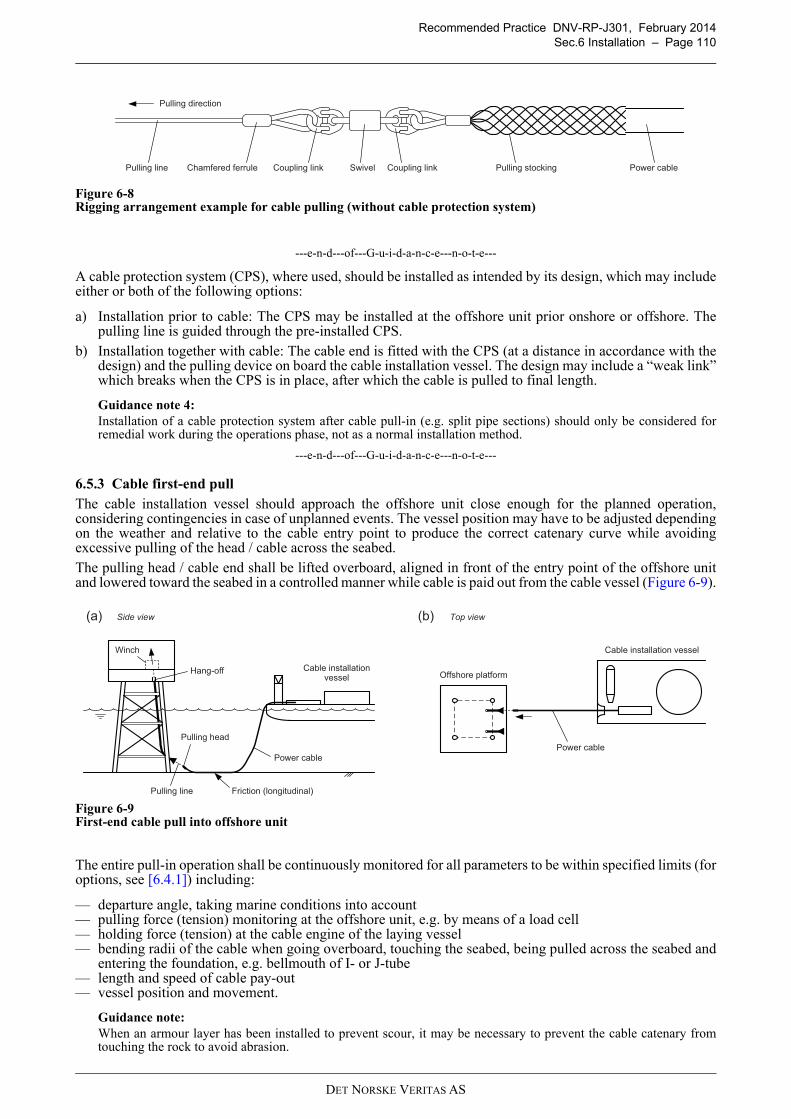
Recommended Practice DNV-RP-J301, February 2014
Sec.6 Installation – Page 110
Figure 6-8Rigging arrangement example for cable pulling (without cable protection system)
---e-n-d---of---G-u-i-d-a-n-c-e---n-o-t-e---
A cable protection system (CPS), where used, should be installed as intended by its design, which may includeeither or both of the following options:
a) Installation prior to cable: The CPS may be installed at the offshore unit prior onshore or offshore. Thepulling line is guided through the pre-installed CPS.
b) Installation together with cable: The cable end is fitted with the CPS (at a distance in accordance with thedesign) and the pulling device on board the cable installation vessel. The design may include a “weak link”which breaks when the CPS is in place, after which the cable is pulled to final length.
Guidance note 4:
Installation of a cable protection system after cable pull-in (e.g. split pipe sections) should only be considered forremedial work during the operations phase, not as a normal installation method.
---e-n-d---of---G-u-i-d-a-n-c-e---n-o-t-e---
6.5.3 Cable first-end pull
The cable installation vessel should approach the offshore unit close enough for the planned operation,considering contingencies in case of unplanned events. The vessel position may have to be adjusted dependingon the weather and relative to the cable entry point to produce the correct catenary curve while avoidingexcessive pulling of the head / cable across the seabed.
The pulling head / cable end shall be lifted overboard, aligned in front of the entry point of the offshore unitand lowered toward the seabed in a controlled manner while cable is paid out from the cable vessel (Figure 6-9).
Figure 6-9First-end cable pull into offshore unit
The entire pull-in operation shall be continuously monitored for all parameters to be within specified limits (foroptions, see [6.4.1]) including:
— departure angle, taking marine conditions into account— pulling force (tension) monitoring at the offshore unit, e.g. by means of a load cell— holding force (tension) at the cable engine of the laying vessel— bending radii of the cable when going overboard, touching the seabed, being pulled across the seabed and
entering the foundation, e.g. bellmouth of I- or J-tube— length and speed of cable pay-out— vessel position and movement.
Guidance note:
When an armour layer has been installed to prevent scour, it may be necessary to prevent the cable catenary fromtouching the rock to avoid abrasion.
Pulling line Coupling link Swivel Coupling link Pulling stocking Power cableChamfered ferrule
Pulling direction
(a) (b)Side view Top view
Winch
Friction (longitudinal)
Pulling head
Pulling line
Power cable
Offshore platform
Cable installation vessel
Power cable
Hang-off Cable installationvessel
DET NORSKE VERITAS AS
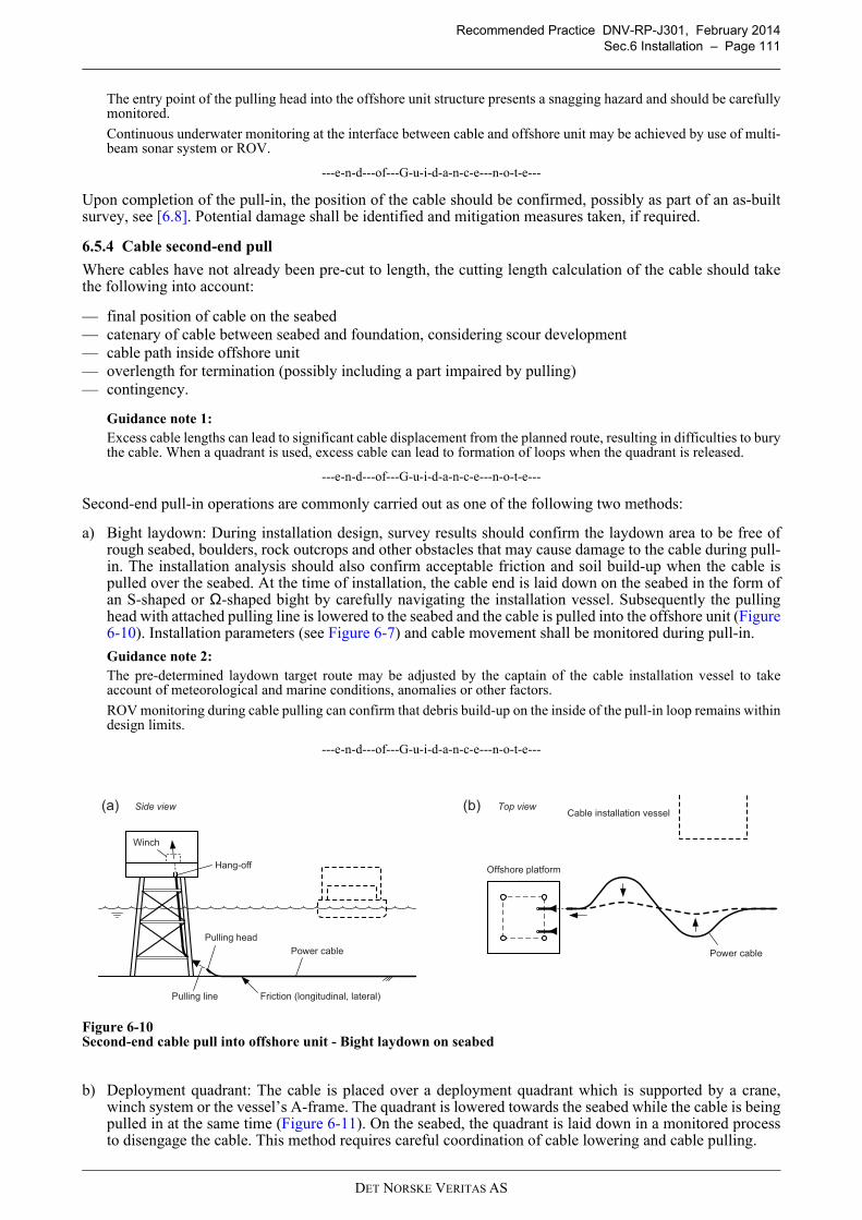
Recommended Practice DNV-RP-J301, February 2014
Sec.6 Installation – Page 111
The entry point of the pulling head into the offshore unit structure presents a snagging hazard and should be carefullymonitored.
Continuous underwater monitoring at the interface between cable and offshore unit may be achieved by use of multi-beam sonar system or ROV.
---e-n-d---of---G-u-i-d-a-n-c-e---n-o-t-e---
Upon completion of the pull-in, the position of the cable should be confirmed, possibly as part of an as-builtsurvey, see [6.8]. Potential damage shall be identified and mitigation measures taken, if required.
6.5.4 Cable second-end pull
Where cables have not already been pre-cut to length, the cutting length calculation of the cable should takethe following into account:
— final position of cable on the seabed— catenary of cable between seabed and foundation, considering scour development— cable path inside offshore unit— overlength for termination (possibly including a part impaired by pulling)— contingency.
Guidance note 1:
Excess cable lengths can lead to significant cable displacement from the planned route, resulting in difficulties to burythe cable. When a quadrant is used, excess cable can lead to formation of loops when the quadrant is released.
---e-n-d---of---G-u-i-d-a-n-c-e---n-o-t-e---
Second-end pull-in operations are commonly carried out as one of the following two methods:
a) Bight laydown: During installation design, survey results should confirm the laydown area to be free ofrough seabed, boulders, rock outcrops and other obstacles that may cause damage to the cable during pull-in. The installation analysis should also confirm acceptable friction and soil build-up when the cable ispulled over the seabed. At the time of installation, the cable end is laid down on the seabed in the form ofan S-shaped or Ω-shaped bight by carefully navigating the installation vessel. Subsequently the pullinghead with attached pulling line is lowered to the seabed and the cable is pulled into the offshore unit (Figure6-10). Installation parameters (see Figure 6-7) and cable movement shall be monitored during pull-in.
Guidance note 2:
The pre-determined laydown target route may be adjusted by the captain of the cable installation vessel to takeaccount of meteorological and marine conditions, anomalies or other factors.
ROV monitoring during cable pulling can confirm that debris build-up on the inside of the pull-in loop remains withindesign limits.
---e-n-d---of---G-u-i-d-a-n-c-e---n-o-t-e---
Figure 6-10Second-end cable pull into offshore unit - Bight laydown on seabed
b) Deployment quadrant: The cable is placed over a deployment quadrant which is supported by a crane,winch system or the vessel’s A-frame. The quadrant is lowered towards the seabed while the cable is beingpulled in at the same time (Figure 6-11). On the seabed, the quadrant is laid down in a monitored processto disengage the cable. This method requires careful coordination of cable lowering and cable pulling.
(a) Side view
Winch
Friction (longitudinal, lateral)
Pulling head
Pulling line
Power cable
Hang-off
(b) Top view
Offshore platform
Power cable
Cable installation vessel
DET NORSKE VERITAS AS
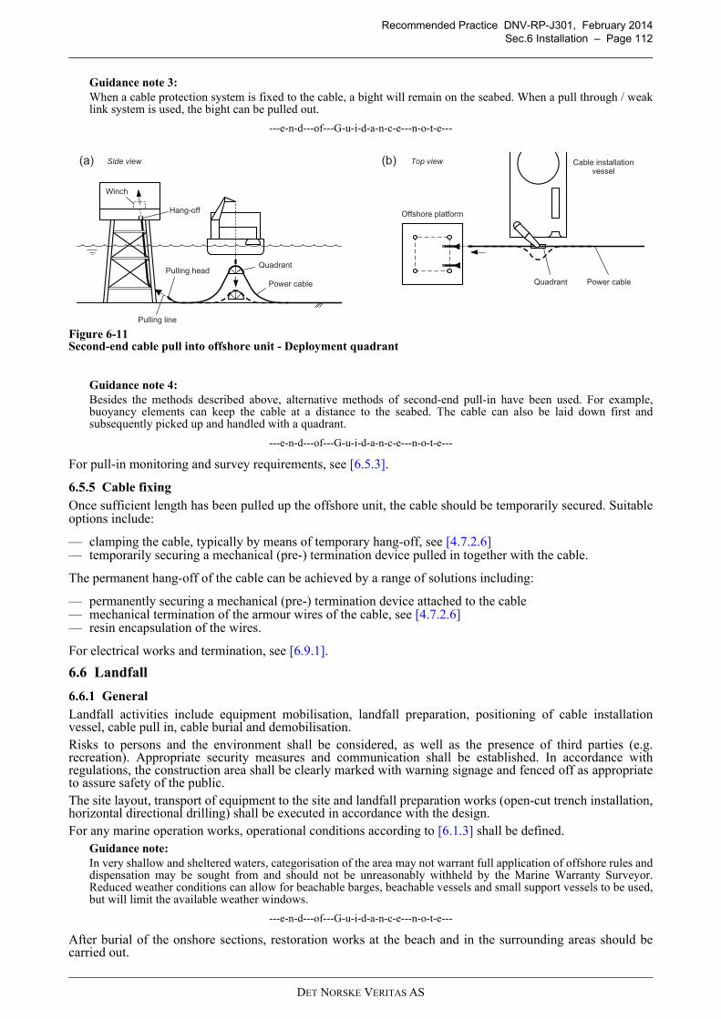
Recommended Practice DNV-RP-J301, February 2014
Sec.6 Installation – Page 112
Guidance note 3:
When a cable protection system is fixed to the cable, a bight will remain on the seabed. When a pull through / weaklink system is used, the bight can be pulled out.
---e-n-d---of---G-u-i-d-a-n-c-e---n-o-t-e---
Figure 6-11Second-end cable pull into offshore unit - Deployment quadrant
Guidance note 4:
Besides the methods described above, alternative methods of second-end pull-in have been used. For example,buoyancy elements can keep the cable at a distance to the seabed. The cable can also be laid down first andsubsequently picked up and handled with a quadrant.
---e-n-d---of---G-u-i-d-a-n-c-e---n-o-t-e---
For pull-in monitoring and survey requirements, see [6.5.3].
6.5.5 Cable fixing
Once sufficient length has been pulled up the offshore unit, the cable should be temporarily secured. Suitableoptions include:
— clamping the cable, typically by means of temporary hang-off, see [4.7.2.6]— temporarily securing a mechanical (pre-) termination device pulled in together with the cable.
The permanent hang-off of the cable can be achieved by a range of solutions including:
— permanently securing a mechanical (pre-) termination device attached to the cable— mechanical termination of the armour wires of the cable, see [4.7.2.6]— resin encapsulation of the wires.
For electrical works and termination, see [6.9.1].
6.6 Landfall
6.6.1 General
Landfall activities include equipment mobilisation, landfall preparation, positioning of cable installationvessel, cable pull in, cable burial and demobilisation.Risks to persons and the environment shall be considered, as well as the presence of third parties (e.g.recreation). Appropriate security measures and communication shall be established. In accordance withregulations, the construction area shall be clearly marked with warning signage and fenced off as appropriateto assure safety of the public.The site layout, transport of equipment to the site and landfall preparation works (open-cut trench installation,horizontal directional drilling) shall be executed in accordance with the design.For any marine operation works, operational conditions according to [6.1.3] shall be defined.
Guidance note:
In very shallow and sheltered waters, categorisation of the area may not warrant full application of offshore rules anddispensation may be sought from and should not be unreasonably withheld by the Marine Warranty Surveyor.Reduced weather conditions can allow for beachable barges, beachable vessels and small support vessels to be used,but will limit the available weather windows.
---e-n-d---of---G-u-i-d-a-n-c-e---n-o-t-e---
After burial of the onshore sections, restoration works at the beach and in the surrounding areas should becarried out.
(a) (b)Side view Top view
Pulling head
Pulling line
Power cable
Offshore platform
Power cable
Hang-off
Quadrant
Quadrant
Cable installation vessel
Winch
DET NORSKE VERITAS AS
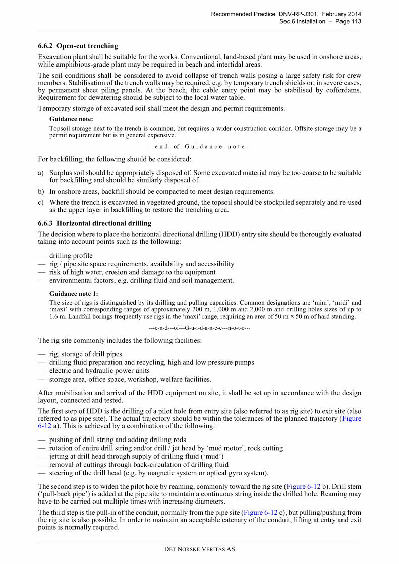
Recommended Practice DNV-RP-J301, February 2014
Sec.6 Installation – Page 113
6.6.2 Open-cut trenching
Excavation plant shall be suitable for the works. Conventional, land-based plant may be used in onshore areas,while amphibious-grade plant may be required in beach and intertidal areas.
The soil conditions shall be considered to avoid collapse of trench walls posing a large safety risk for crewmembers. Stabilisation of the trench walls may be required, e.g. by temporary trench shields or, in severe cases,by permanent sheet piling panels. At the beach, the cable entry point may be stabilised by cofferdams.Requirement for dewatering should be subject to the local water table.
Temporary storage of excavated soil shall meet the design and permit requirements.
Guidance note:
Topsoil storage next to the trench is common, but requires a wider construction corridor. Offsite storage may be apermit requirement but is in general expensive.
---e-n-d---of---G-u-i-d-a-n-c-e---n-o-t-e---
For backfilling, the following should be considered:
a) Surplus soil should be appropriately disposed of. Some excavated material may be too coarse to be suitablefor backfilling and should be similarly disposed of.
b) In onshore areas, backfill should be compacted to meet design requirements.
c) Where the trench is excavated in vegetated ground, the topsoil should be stockpiled separately and re-usedas the upper layer in backfilling to restore the trenching area.
6.6.3 Horizontal directional drilling
The decision where to place the horizontal directional drilling (HDD) entry site should be thoroughly evaluatedtaking into account points such as the following:
— drilling profile— rig / pipe site space requirements, availability and accessibility— risk of high water, erosion and damage to the equipment— environmental factors, e.g. drilling fluid and soil management.
Guidance note 1:
The size of rigs is distinguished by its drilling and pulling capacities. Common designations are ‘mini’, ‘midi’ and‘maxi’ with corresponding ranges of approximately 200 m, 1,000 m and 2,000 m and drilling holes sizes of up to1.6 m. Landfall borings frequently use rigs in the ‘maxi’ range, requiring an area of 50 m × 50 m of hard standing.
---e-n-d---of---G-u-i-d-a-n-c-e---n-o-t-e---
The rig site commonly includes the following facilities:
— rig, storage of drill pipes— drilling fluid preparation and recycling, high and low pressure pumps— electric and hydraulic power units— storage area, office space, workshop, welfare facilities.
After mobilisation and arrival of the HDD equipment on site, it shall be set up in accordance with the designlayout, connected and tested.
The first step of HDD is the drilling of a pilot hole from entry site (also referred to as rig site) to exit site (alsoreferred to as pipe site). The actual trajectory should be within the tolerances of the planned trajectory (Figure6-12 a). This is achieved by a combination of the following:
— pushing of drill string and adding drilling rods— rotation of entire drill string and/or drill / jet head by ‘mud motor’, rock cutting— jetting at drill head through supply of drilling fluid (‘mud’)— removal of cuttings through back-circulation of drilling fluid— steering of the drill head (e.g. by magnetic system or optical gyro system).
The second step is to widen the pilot hole by reaming, commonly toward the rig site (Figure 6-12 b). Drill stem(‘pull-back pipe’) is added at the pipe site to maintain a continuous string inside the drilled hole. Reaming mayhave to be carried out multiple times with increasing diameters.
The third step is the pull-in of the conduit, normally from the pipe site (Figure 6-12 c), but pulling/pushing fromthe rig site is also possible. In order to maintain an acceptable catenary of the conduit, lifting at entry and exitpoints is normally required.
DET NORSKE VERITAS AS
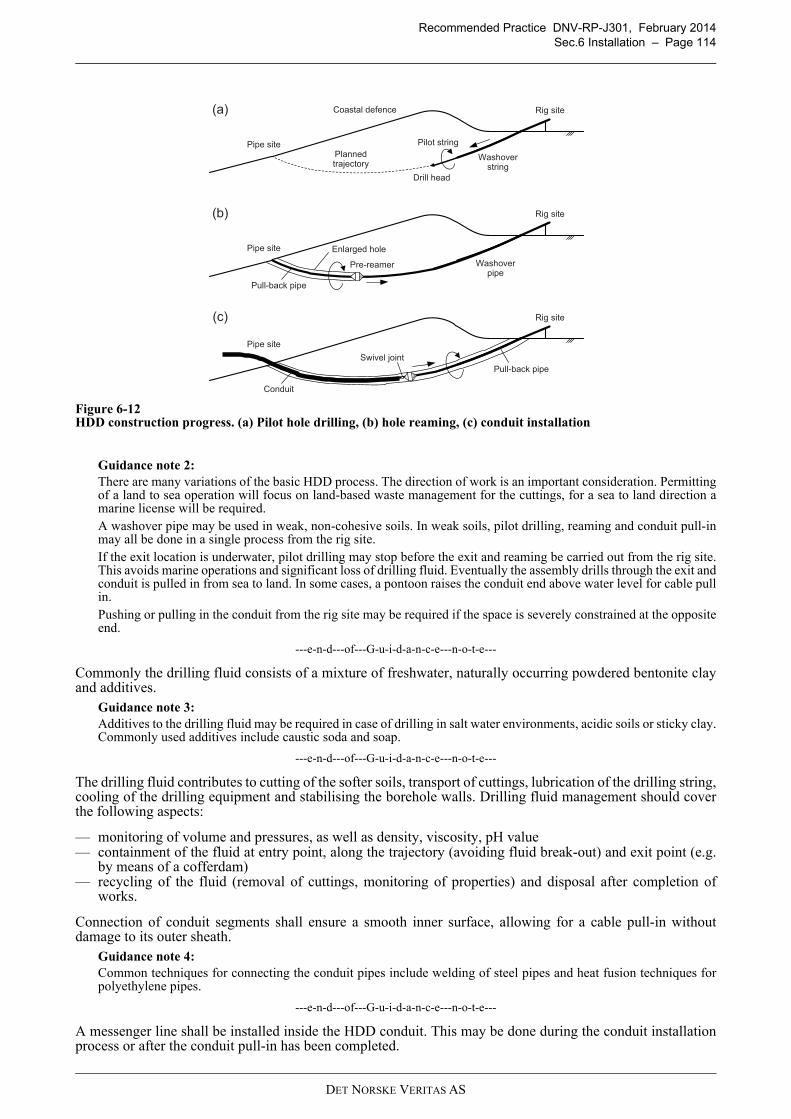
Recommended Practice DNV-RP-J301, February 2014
Sec.6 Installation – Page 114
Figure 6-12HDD construction progress. (a) Pilot hole drilling, (b) hole reaming, (c) conduit installation
Guidance note 2:
There are many variations of the basic HDD process. The direction of work is an important consideration. Permittingof a land to sea operation will focus on land-based waste management for the cuttings, for a sea to land direction amarine license will be required.A washover pipe may be used in weak, non-cohesive soils. In weak soils, pilot drilling, reaming and conduit pull-inmay all be done in a single process from the rig site.If the exit location is underwater, pilot drilling may stop before the exit and reaming be carried out from the rig site.This avoids marine operations and significant loss of drilling fluid. Eventually the assembly drills through the exit andconduit is pulled in from sea to land. In some cases, a pontoon raises the conduit end above water level for cable pullin.Pushing or pulling in the conduit from the rig site may be required if the space is severely constrained at the oppositeend.
---e-n-d---of---G-u-i-d-a-n-c-e---n-o-t-e---
Commonly the drilling fluid consists of a mixture of freshwater, naturally occurring powdered bentonite clayand additives.
Guidance note 3:
Additives to the drilling fluid may be required in case of drilling in salt water environments, acidic soils or sticky clay.Commonly used additives include caustic soda and soap.
---e-n-d---of---G-u-i-d-a-n-c-e---n-o-t-e---
The drilling fluid contributes to cutting of the softer soils, transport of cuttings, lubrication of the drilling string,cooling of the drilling equipment and stabilising the borehole walls. Drilling fluid management should coverthe following aspects:
— monitoring of volume and pressures, as well as density, viscosity, pH value— containment of the fluid at entry point, along the trajectory (avoiding fluid break-out) and exit point (e.g.
by means of a cofferdam)— recycling of the fluid (removal of cuttings, monitoring of properties) and disposal after completion of
works.
Connection of conduit segments shall ensure a smooth inner surface, allowing for a cable pull-in withoutdamage to its outer sheath.
Guidance note 4:
Common techniques for connecting the conduit pipes include welding of steel pipes and heat fusion techniques forpolyethylene pipes.
---e-n-d---of---G-u-i-d-a-n-c-e---n-o-t-e---
A messenger line shall be installed inside the HDD conduit. This may be done during the conduit installationprocess or after the conduit pull-in has been completed.
Rig site
Planned trajectory
Coastal defence
Pipe site
Drill head
Washoverstring
Pilot string
(a)
Rig site
Pipe site
Pre-reamer Washoverpipe
Pull-back pipe
(b)
Enlarged hole
Rig site
Pipe site
Swivel joint
Pull-back pipe
Conduit
(c)
DET NORSKE VERITAS AS
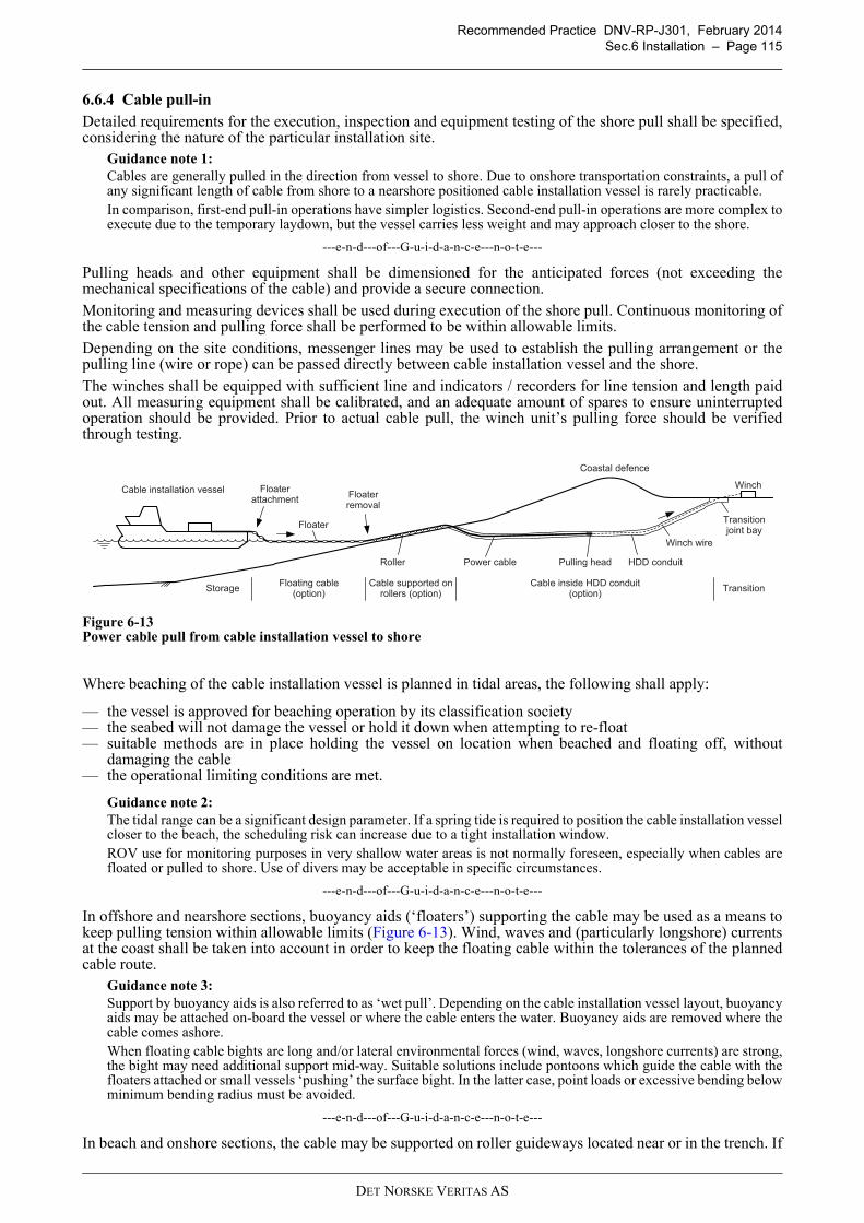
Recommended Practice DNV-RP-J301, February 2014
Sec.6 Installation – Page 115
6.13
6.6.4 Cable pull-in
Detailed requirements for the execution, inspection and equipment testing of the shore pull shall be specified,considering the nature of the particular installation site.
Guidance note 1:
Cables are generally pulled in the direction from vessel to shore. Due to onshore transportation constraints, a pull ofany significant length of cable from shore to a nearshore positioned cable installation vessel is rarely practicable.In comparison, first-end pull-in operations have simpler logistics. Second-end pull-in operations are more complex toexecute due to the temporary laydown, but the vessel carries less weight and may approach closer to the shore.
---e-n-d---of---G-u-i-d-a-n-c-e---n-o-t-e---
Pulling heads and other equipment shall be dimensioned for the anticipated forces (not exceeding themechanical specifications of the cable) and provide a secure connection.
Monitoring and measuring devices shall be used during execution of the shore pull. Continuous monitoring ofthe cable tension and pulling force shall be performed to be within allowable limits.
Depending on the site conditions, messenger lines may be used to establish the pulling arrangement or thepulling line (wire or rope) can be passed directly between cable installation vessel and the shore.
The winches shall be equipped with sufficient line and indicators / recorders for line tension and length paidout. All measuring equipment shall be calibrated, and an adequate amount of spares to ensure uninterruptedoperation should be provided. Prior to actual cable pull, the winch unit’s pulling force should be verifiedthrough testing.
Figure 6-13Power cable pull from cable installation vessel to shore
Where beaching of the cable installation vessel is planned in tidal areas, the following shall apply:
— the vessel is approved for beaching operation by its classification society— the seabed will not damage the vessel or hold it down when attempting to re-float— suitable methods are in place holding the vessel on location when beached and floating off, without
damaging the cable— the operational limiting conditions are met.
Guidance note 2:
The tidal range can be a significant design parameter. If a spring tide is required to position the cable installation vesselcloser to the beach, the scheduling risk can increase due to a tight installation window.ROV use for monitoring purposes in very shallow water areas is not normally foreseen, especially when cables arefloated or pulled to shore. Use of divers may be acceptable in specific circumstances.
---e-n-d---of---G-u-i-d-a-n-c-e---n-o-t-e---
In offshore and nearshore sections, buoyancy aids (‘floaters’) supporting the cable may be used as a means tokeep pulling tension within allowable limits (Figure 6-13). Wind, waves and (particularly longshore) currentsat the coast shall be taken into account in order to keep the floating cable within the tolerances of the plannedcable route.
Guidance note 3:
Support by buoyancy aids is also referred to as ‘wet pull’. Depending on the cable installation vessel layout, buoyancyaids may be attached on-board the vessel or where the cable enters the water. Buoyancy aids are removed where thecable comes ashore.When floating cable bights are long and/or lateral environmental forces (wind, waves, longshore currents) are strong,the bight may need additional support mid-way. Suitable solutions include pontoons which guide the cable with thefloaters attached or small vessels ‘pushing’ the surface bight. In the latter case, point loads or excessive bending belowminimum bending radius must be avoided.
---e-n-d---of---G-u-i-d-a-n-c-e---n-o-t-e---
In beach and onshore sections, the cable may be supported on roller guideways located near or in the trench. If
Cable installation vesselWinch
Power cable
Coastal defence
Winch wire
HDD conduit
Transitionjoint bay
Pulling head
Floaterattachment
Floaterremoval
Roller
Floater
Floating cable(option)
Cable supported on rollers (option)
Cable inside HDD conduit(option)
TransitionStorage
DET NORSKE VERITAS AS
Recommended Practice DNV-RP-J301, February 2014
Sec.6 Installation – Page 116
the design includes a horizontal bend in the shore area, a beach quadrant or alternative method complying withthe minimum bending radius shall be used to alter the cable course.
Guidance note 4:
Support by roller guideways is also referred to as ‘dry pull’. The roller blocks should be of a stable design and haveno sharp edges. Support on three sides (“U” shape) rather than two sides (“V” shape) is advantageous, in particularwhen the cable is not torsion balanced. The roller design should ensure that the cable is not sliding but rolling. Thebeach rollers should be placed at such a distance from each other that mechanical parameters of the cable are notcompromised.Where powered and synchronised cable pulling machines are placed along the cable path, the pulling distance can beincreased to several kilometres.A roller cradle supported from an excavator can be used to position the cable into an open-cut trench.
---e-n-d---of---G-u-i-d-a-n-c-e---n-o-t-e---
Friction forces during pull into HDD conduit may be lowered through the use of lubrication (mineral slurries,gels or bio-degradable oils) or by filling the conduit with water or drilling fluid.
After the cable has been secured in the transition joint bay ([6.6.5]), the cable rollers may be removed and thecable installation vessel can continue laying the remainder of the cable ([6.4.1]).
Depending on the specific design, the HDD conduit may be filled with fluidised thermal backfill after cablepull-in.
6.6.5 Interface with land-based system
The transition joint bay area shall be constructed in accordance with the design documentation. Depending onits location, temporary measures for dewatering may be required.
When the necessary length of subsea cable has been pulled in, the cable shall be mechanically secured(anchored) in / at the transition joint bay.
The jointing of subsea and land-based cables at the transition joint bay shall be carried out in accordance withthe procedure developed for the particular cables and approved by the cables’ manufacturers.
After jointing of subsea and land-based cables, the transition joint bay should be closed and secured. Wherefeasible, accessibility to the pit should be retained for the operational life of the project in order to ensure itsmaintainability.
Following cable installation works, the site may have to be restored.
6.7 Cable protection
6.7.1 General
The requirements of this subsection are applicable to the protection of cables, e.g. direct burial includingtrenching and backfilling, and other methods such as gravel and/or rock placement, grout bags, concretemattresses, etc. It is also applicable to free span rectification.A specific survey of the work area should be performed or supplement the pre-installation survey if conditionslisted in [6.3.1] apply.
6.7.2 Cable burial
In preparation of burial operations it should be confirmed that:
— the required cable trench depth is defined relative to the mean surrounding seabed— the trenching method for the given cable submerged weight, soil properties and near-bed hydrodynamic
conditions does not cause cable floatation during the trenching and backfilling operations— during burial operations of cable bundles, strapping arrangements will not interfere with the operation.
Where pre-lay trenching is performed:
— the required trench geometry should be defined— it should be documented that the trench is stable and will not be backfilled above the design level before
cable installation— the trench should be cleaned if excessive backfill develops prior to cable installation.
Where simultaneous lay and burial (SLB) is performed:
— cable catenary management ([6.4.1]) should not be adversely affected by operation of the burial device— direct feedback from the burial device should be used for positioning and heading of the cable installation
vessel.
Where post lay burial (PLB) is performed:
— the trenching equipment shall be designed so that it does not place significant loads on the cable and that itminimises the possibility of cable damage
DET NORSKE VERITAS AS
Recommended Practice DNV-RP-J301, February 2014
Sec.6 Installation – Page 117
— the loading of the cable should preferably be performed without divers— cable tension in front of the trenching equipment should be understood / managed to avoid cable damage— in beach areas, self-burial of the cable can occur, therefore the cable location may require recording /
marking.
Where mechanical backfilling is performed:
— it should be carried out in a manner that minimises the possibility of damage to the cable— the operation should be suitably monitored.
The trenching spread shall be equipped with sufficient instrumentation to ensure that excessive cable contactand damage to cable (outer serving, internal) are avoided. The burial equipment monitoring system shall becalibrated and may include:
— devices to measure trenching and cable depth relative to the seabed and relative to the applied datum (withquantified uncertainties for horizontal and vertical position)
— a monitoring system and control system preventing horizontal loads on the cable or devices to measure andrecord all vertical and horizontal forces imposed on the cable by trenching equipment, and devices tomeasure the proximity of the trenching equipment to the cable, horizontally and vertically relative to thecable
— underwater monitoring systems enabling the trenching equipment operator to view the cable and seabedprofile forward and aft of the trenching equipment, as applicable
— measuring and recording devices for trenching equipment tow force, if applicable— devices monitoring pitch, roll, depth, and the absolute underwater position of the burial equipment.
An allowable range of values, indicated by the measuring devices of the burial equipment, shall be established,see [4.6.3.4]. During trenching operations the measuring devices shall be continuously monitored. Recordsshould be produced for future reference.
A post-burial survey should be performed in order to determine if the required depth of lowering and depth ofcover have been achieved and if any remedial work is required, see [6.8].
6.7.3 Non-burial protection
6.7.3.1 Tubular products
Tubular products shall meet the design specifications, see [4.6.4.2], [4.7.4] and [5.5].
Where the cable with fitted tubular product is transported on rollers, tracks, guides, chutes or quadrants, thedesign shall ensure smooth and controlled movement. Deployment of the cable assembly should be testedbefore installation commences, see [5.5].
For installation designs where cable and tubular product are deployed together, assembly on deck of the cableinstallation vessel shall ensure that the product is secured around the cable before deployment.
Upon completion of the installation works, a post-installation survey should be performed to confirm correctlocation and compliance with other design requirements, see [6.8].
6.7.3.2 Mattresses and bags
Concrete / bitumen mattresses and grout / rock bags (‘gabion bags’) shall meet the specification with regard tosize, shape and flexibility of the units and the specific gravity, composition and grading of the filling material(see [4.6.4.3]).
Placing of mattresses and bags shall be performed in a controlled manner, such that the mattresses or bags areplaced as required. Restrictions on vessel movements during the operation shall be given.
During the placement operations, inspections shall be performed, e.g. with an ROV-mounted video camera, todetermine the completeness and adequacy of the installation.
Mattresses with added frond systems should be installed using the same methods as conventional mattresses.Roll-out fronded mattresses require specific engineering and risk assessment.
Guidance note:
For details on diver and ROV based concrete mattress handling, deployment, installation, repositioning anddecommissioning, see IMCA D 042 (R 016). The use of divers should be avoided.
---e-n-d---of---G-u-i-d-a-n-c-e---n-o-t-e---
Upon completion of the placing operation, an as-built survey should be performed to confirm compliance withthe design requirements, see [6.8].
6.7.3.3 Rock placement
Material used for rock installation shall meet the specified requirements for specific gravity, composition andgrading (see [4.6.4.4]).
DET NORSKE VERITAS AS
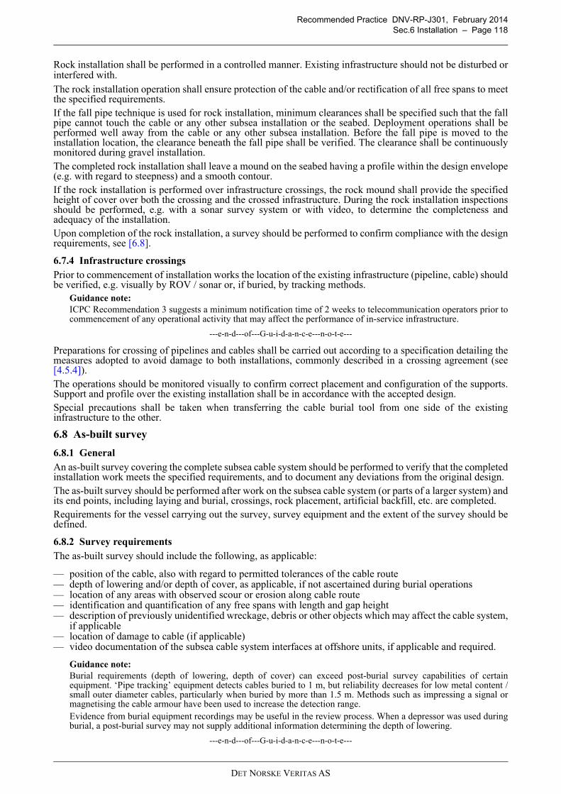
Recommended Practice DNV-RP-J301, February 2014
Sec.6 Installation – Page 118
Rock installation shall be performed in a controlled manner. Existing infrastructure should not be disturbed orinterfered with.
The rock installation operation shall ensure protection of the cable and/or rectification of all free spans to meetthe specified requirements.If the fall pipe technique is used for rock installation, minimum clearances shall be specified such that the fallpipe cannot touch the cable or any other subsea installation or the seabed. Deployment operations shall beperformed well away from the cable or any other subsea installation. Before the fall pipe is moved to theinstallation location, the clearance beneath the fall pipe shall be verified. The clearance shall be continuouslymonitored during gravel installation.The completed rock installation shall leave a mound on the seabed having a profile within the design envelope(e.g. with regard to steepness) and a smooth contour.If the rock installation is performed over infrastructure crossings, the rock mound shall provide the specifiedheight of cover over both the crossing and the crossed infrastructure. During the rock installation inspectionsshould be performed, e.g. with a sonar survey system or with video, to determine the completeness andadequacy of the installation.Upon completion of the rock installation, a survey should be performed to confirm compliance with the designrequirements, see [6.8].
6.7.4 Infrastructure crossings
Prior to commencement of installation works the location of the existing infrastructure (pipeline, cable) shouldbe verified, e.g. visually by ROV / sonar or, if buried, by tracking methods.
Guidance note:
ICPC Recommendation 3 suggests a minimum notification time of 2 weeks to telecommunication operators prior tocommencement of any operational activity that may affect the performance of in-service infrastructure.
---e-n-d---of---G-u-i-d-a-n-c-e---n-o-t-e---
Preparations for crossing of pipelines and cables shall be carried out according to a specification detailing themeasures adopted to avoid damage to both installations, commonly described in a crossing agreement (see[4.5.4]).The operations should be monitored visually to confirm correct placement and configuration of the supports.Support and profile over the existing installation shall be in accordance with the accepted design.Special precautions shall be taken when transferring the cable burial tool from one side of the existinginfrastructure to the other.
6.8 As-built survey
6.8.1 General
An as-built survey covering the complete subsea cable system should be performed to verify that the completedinstallation work meets the specified requirements, and to document any deviations from the original design.The as-built survey should be performed after work on the subsea cable system (or parts of a larger system) andits end points, including laying and burial, crossings, rock placement, artificial backfill, etc. are completed.Requirements for the vessel carrying out the survey, survey equipment and the extent of the survey should bedefined.
6.8.2 Survey requirements
The as-built survey should include the following, as applicable:
— position of the cable, also with regard to permitted tolerances of the cable route— depth of lowering and/or depth of cover, as applicable, if not ascertained during burial operations— location of any areas with observed scour or erosion along cable route— identification and quantification of any free spans with length and gap height— description of previously unidentified wreckage, debris or other objects which may affect the cable system,
if applicable— location of damage to cable (if applicable)— video documentation of the subsea cable system interfaces at offshore units, if applicable and required.
Guidance note:
Burial requirements (depth of lowering, depth of cover) can exceed post-burial survey capabilities of certainequipment. ‘Pipe tracking’ equipment detects cables buried to 1 m, but reliability decreases for low metal content /small outer diameter cables, particularly when buried by more than 1.5 m. Methods such as impressing a signal ormagnetising the cable armour have been used to increase the detection range.Evidence from burial equipment recordings may be useful in the review process. When a depressor was used duringburial, a post-burial survey may not supply additional information determining the depth of lowering.
---e-n-d---of---G-u-i-d-a-n-c-e---n-o-t-e---
DET NORSKE VERITAS AS
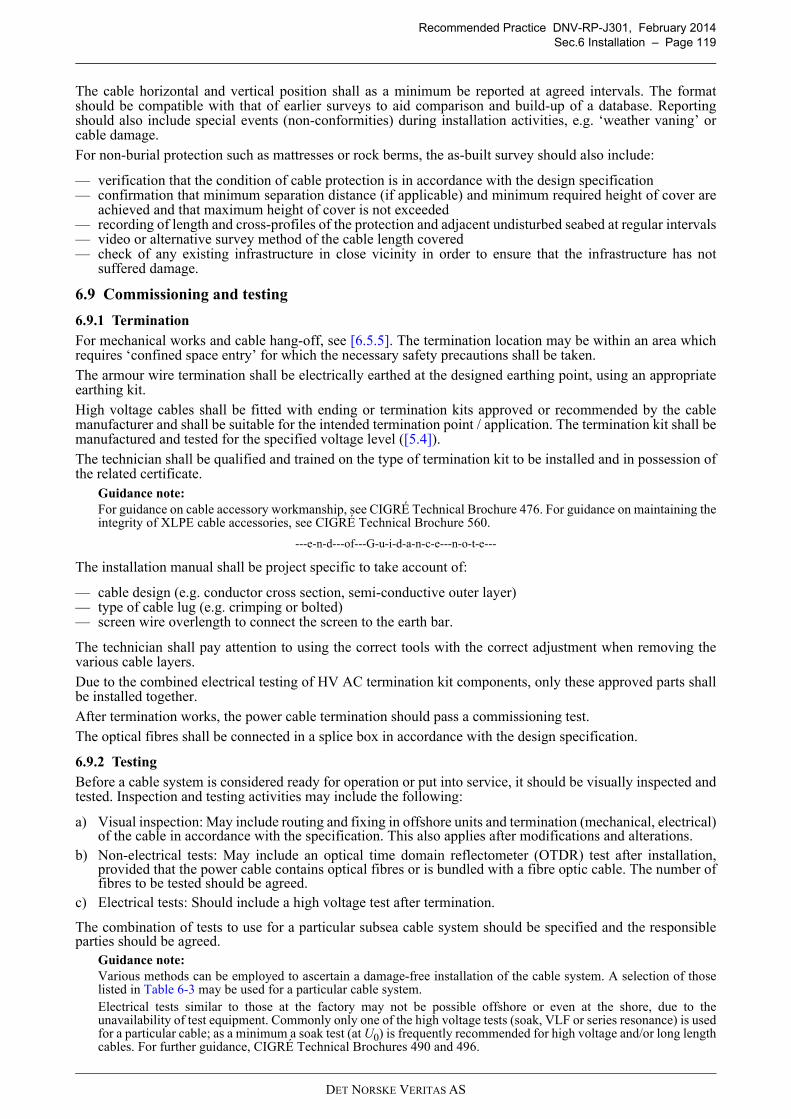
Recommended Practice DNV-RP-J301, February 2014
Sec.6 Installation – Page 119
The cable horizontal and vertical position shall as a minimum be reported at agreed intervals. The formatshould be compatible with that of earlier surveys to aid comparison and build-up of a database. Reportingshould also include special events (non-conformities) during installation activities, e.g. ‘weather vaning’ orcable damage.
For non-burial protection such as mattresses or rock berms, the as-built survey should also include:
— verification that the condition of cable protection is in accordance with the design specification— confirmation that minimum separation distance (if applicable) and minimum required height of cover are
achieved and that maximum height of cover is not exceeded— recording of length and cross-profiles of the protection and adjacent undisturbed seabed at regular intervals— video or alternative survey method of the cable length covered— check of any existing infrastructure in close vicinity in order to ensure that the infrastructure has not
suffered damage.
6.9 Commissioning and testing
6.9.1 Termination
For mechanical works and cable hang-off, see [6.5.5]. The termination location may be within an area whichrequires ‘confined space entry’ for which the necessary safety precautions shall be taken.
The armour wire termination shall be electrically earthed at the designed earthing point, using an appropriateearthing kit.
High voltage cables shall be fitted with ending or termination kits approved or recommended by the cablemanufacturer and shall be suitable for the intended termination point / application. The termination kit shall bemanufactured and tested for the specified voltage level ([5.4]).
The technician shall be qualified and trained on the type of termination kit to be installed and in possession ofthe related certificate.
Guidance note:
For guidance on cable accessory workmanship, see CIGRÉ Technical Brochure 476. For guidance on maintaining theintegrity of XLPE cable accessories, see CIGRÉ Technical Brochure 560.
---e-n-d---of---G-u-i-d-a-n-c-e---n-o-t-e---
The installation manual shall be project specific to take account of:
— cable design (e.g. conductor cross section, semi-conductive outer layer)— type of cable lug (e.g. crimping or bolted)— screen wire overlength to connect the screen to the earth bar.
The technician shall pay attention to using the correct tools with the correct adjustment when removing thevarious cable layers.
Due to the combined electrical testing of HV AC termination kit components, only these approved parts shallbe installed together.
After termination works, the power cable termination should pass a commissioning test.
The optical fibres shall be connected in a splice box in accordance with the design specification.
6.9.2 Testing
Before a cable system is considered ready for operation or put into service, it should be visually inspected andtested. Inspection and testing activities may include the following:
a) Visual inspection: May include routing and fixing in offshore units and termination (mechanical, electrical)of the cable in accordance with the specification. This also applies after modifications and alterations.
b) Non-electrical tests: May include an optical time domain reflectometer (OTDR) test after installation,provided that the power cable contains optical fibres or is bundled with a fibre optic cable. The number offibres to be tested should be agreed.
c) Electrical tests: Should include a high voltage test after termination.
The combination of tests to use for a particular subsea cable system should be specified and the responsibleparties should be agreed.
Guidance note:
Various methods can be employed to ascertain a damage-free installation of the cable system. A selection of thoselisted in Table 6-3 may be used for a particular cable system.Electrical tests similar to those at the factory may not be possible offshore or even at the shore, due to theunavailability of test equipment. Commonly only one of the high voltage tests (soak, VLF or series resonance) is usedfor a particular cable; as a minimum a soak test (at U0) is frequently recommended for high voltage and/or long lengthcables. For further guidance, CIGRÉ Technical Brochures 490 and 496.
DET NORSKE VERITAS AS
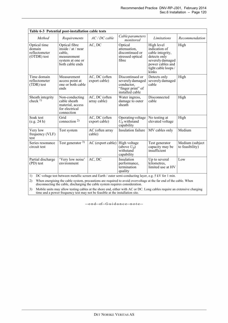
Recommended Practice DNV-RP-J301, February 2014
Sec.6 Installation – Page 120
---e-n-d---of---G-u-i-d-a-n-c-e---n-o-t-e---
Table 6-3 Potential post-installation cable tests
Method Requirements AC / DC cableCable parameters
monitoredLimitations Recommendation
Optical time domain reflectometer (OTDR) test
Optical fibre inside / at / near cable, measurement system at one or both cable ends
AC, DC Optical attenuation, discontinued or stressed optical fibre
High level indication of cable integrity, detects only severely damaged power cables and tight cable loops / kinks
High
Time domain reflectometer (TDR) test
Measurement access point at one or both cable ends
AC, DC (often export cable)
Discontinued or severely damaged conductor, “finger print” of installed cable
Detects only severely damaged cable
High
Sheath integrity check 1)
Non-conducting cable sheath material, access for electrical connection
AC, DC (often array cable)
Water ingress, damage to outer sheath
Disconnected cable
High
Soak test (e.g. 24 h)
Grid connection 2)
AC, DC (often export cable)
Operating voltage U0 withstand capability
No testing at elevated voltage
High
Very low frequency (VLF) test
Test system AC (often array cable)
Insulation failure MV cables only Medium
Series resonance circuit test
Test generator 3) AC (export cable) High voltage (above U0) withstand capability
Test generator capacity may be insufficient
Medium (subject to feasibility)
Partial discharge (PD) test
‘Very low noise’ environment
AC, DC Insulation performance, termination quality
Up to several kilometres, limited use at HV
Low
1) DC voltage test between metallic screen and Earth / outer semi-conducting layer, e.g. 5 kV for 1 min.
2) When energising the cable system, precautions are required to avoid overvoltage at the far end of the cable. When disconnecting the cable, discharging the cable system requires consideration.
3) Mobile units may allow testing cables at the shore end, either with AC or DC. Long cables require an extensive charging time and a power frequency test may not be feasible at the installation site.
DET NORSKE VERITAS AS
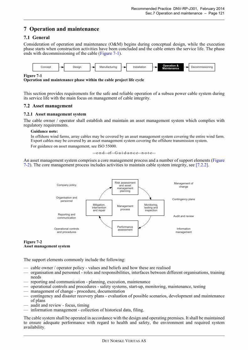
Recommended Practice DNV-RP-J301, February 2014
Sec.7 Operation and maintenance – Page 121
7 Operation and maintenance
7.1 General
Consideration of operation and maintenance (O&M) begins during conceptual design, while the executionphase starts when construction activities have been concluded and the cable enters the service life. The phaseends with decommissioning of the cable (Figure 7-1).
Figure 7-1Operation and maintenance phase within the cable project life cycle
This section provides requirements for the safe and reliable operation of a subsea power cable system duringits service life with the main focus on management of cable integrity.
7.2 Asset management
7.2.1 Asset management system
The cable owner / operator shall establish and maintain an asset management system which complies withregulatory requirements.
Guidance note:
In offshore wind farms, array cables may be covered by an asset management system covering the entire wind farm.Export cables may be covered by an asset management system covering the offshore transmission system.For guidance on asset management, see ISO 55000.
---e-n-d---of---G-u-i-d-a-n-c-e---n-o-t-e---
An asset management system comprises a core management process and a number of support elements (Figure7-2). The core management process includes activities to maintain cable system integrity, see [7.2.2].
Figure 7-2Asset management system
The support elements commonly include the following:
— cable owner / operator policy - values and beliefs and how these are realised— organisation and personnel - roles and responsibilities, interfaces between different organisations, training
needs— reporting and communication - planning, execution, maintenance— operational controls and procedures - safety systems, start-up, monitoring, maintenance, testing— management of change - procedure, documentation— contingency and disaster recovery plans - evaluation of possible scenarios, development and maintenance
of plans— audit and review - focus, timing— information management - collection of historical data, filing.
The cable system shall be operated in accordance with the design and operating premises. It shall be maintainedto ensure adequate performance with regard to health and safety, the environment and required systemavailability.
DesignConceptOperation & Maintenance
Installation DecommissioningManufacturing
Risk assessmentand asset
managementplanning
Mitigation,interventionand repair
Performanceassessment
Monitoring,testing andinspection
Company policy
Organisation and
personnel
Reporting and
communication
Operational controls
and procedures
Management of
change
Contingency plans
Audit and review
Information
management
Management
process
DET NORSKE VERITAS AS
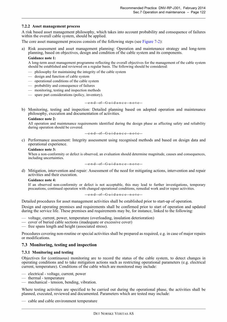
Recommended Practice DNV-RP-J301, February 2014
Sec.7 Operation and maintenance – Page 122
7.2.2 Asset management process
A risk based asset management philosophy, which takes into account probability and consequence of failureswithin the overall cable system, should be applied.The core asset management process consists of the following steps (see Figure 7-2):
a) Risk assessment and asset management planning: Operation and maintenance strategy and long-termplanning, based on objectives, design and condition of the cable system and its components.Guidance note 1:
A long-term asset management programme reflecting the overall objectives for the management of the cable systemshould be established and reviewed on a regular basis. The following should be considered:
— philosophy for maintaining the integrity of the cable system— design and function of cable system— operational conditions of the cable system— probability and consequence of failures— monitoring, testing and inspection methods— spare part considerations (policy, inventory).
---e-n-d---of---G-u-i-d-a-n-c-e---n-o-t-e---
b) Monitoring, testing and inspection: Detailed planning based on adopted operation and maintenancephilosophy, execution and documentation of activities.Guidance note 2:
All operation and maintenance requirements identified during the design phase as affecting safety and reliabilityduring operation should be covered.
---e-n-d---of---G-u-i-d-a-n-c-e---n-o-t-e---
c) Performance assessment: Integrity assessment using recognised methods and based on design data andoperational experience.Guidance note 3:
When a non-conformity or defect is observed, an evaluation should determine magnitude, causes and consequences,including uncertainties.
---e-n-d---of---G-u-i-d-a-n-c-e---n-o-t-e---
d) Mitigation, intervention and repair: Assessment of the need for mitigating actions, intervention and repairactivities and their execution.Guidance note 4:
If an observed non-conformity or defect is not acceptable, this may lead to further investigations, temporaryprecautions, continued operation with changed operational conditions, remedial work and/or repair activities.
---e-n-d---of---G-u-i-d-a-n-c-e---n-o-t-e---
Detailed procedures for asset management activities shall be established prior to start-up of operation.Design and operating premises and requirements shall be confirmed prior to start of operation and updatedduring the service life. These premises and requirements may be, for instance, linked to the following:
— voltage, current, power, temperature (overloading, insulation deterioration)— cover of buried cable sections (inadequate or excessive cover)— free spans length and height (associated stress).
Procedures covering non-routine or special activities shall be prepared as required, e.g. in case of major repairsor modifications.
7.3 Monitoring, testing and inspection
7.3.1 Monitoring and testing
Objectives for (continuous) monitoring are to record the status of the cable system, to detect changes inoperating conditions and to take mitigation actions such as restricting operational parameters (e.g. electricalcurrent, temperature). Conditions of the cable which are monitored may include:
— electrical - voltage, current, power— thermal - temperature— mechanical - tension, bending, vibration.
Where testing activities are specified to be carried out during the operational phase, the activities shall beplanned, executed, reviewed and documented. Parameters which are tested may include:
— cable and cable environment temperature
DET NORSKE VERITAS AS
Recommended Practice DNV-RP-J301, February 2014
Sec.7 Operation and maintenance – Page 123
— partial discharge— cable sheath leakage currents.
The combination of measurements and tests to use for a particular cable system should be subject to a detailedanalysis.
Guidance note:
Various methods can be employed to remotely monitor the conditions of cable systems, see Table 7-1.
Further or alternative methods, such as distributed acoustic sensing / distributed vibration sensing or low voltage radiofrequency testing, can be employed for cable condition monitoring.
---e-n-d---of---G-u-i-d-a-n-c-e---n-o-t-e---
Techniques and equipment for monitoring and testing shall be selected based upon:
— monitoring objectives, including requirements for accuracy and sensitivity— risks for the cable system.
7.3.2 Inspection
A cable verification survey is a survey to determine the position and condition of the cable system and itscomponents. Data from the as-built survey ([6.8]) can normally be used; otherwise specific inspections shouldbe completed within one year from start of operations. In case of significant changes after this first inspection,the need of additional inspections should be determined.
Guidance note 1:
Due to the large size of some projects, operations may start in stages. The inspection planning should reflect this.
---e-n-d---of---G-u-i-d-a-n-c-e---n-o-t-e---
Table 7-1 Potential cable tests during the operational phase
Method Requirements Online / offlineCable parameters
monitoredLimitations Recommendation
Power flow measurement
Voltage / current transformers at cable end(s), SCADA system
online Electrical power, (estimated temperature rise)
Point measurement(s)
High
Distributed temperature sensing (DTS)
Optical fibre inside / at / near cable, measurement system at one/both cable end(s)
online Temperature 1), current rating through real-time thermal rating, inference of degree of burial protection
Several tens of kilometres, resolution better than 2-3 m and ± 1 K 2)
Medium 3)
Distributed strain sensing (DSS)
(Special) optical fibre inside / at / near cable, measurement system at one cable end
online Mechanical stress on cable, e.g. free spans
Several tens of kilometres, no established track record
Low
Partial discharge (PD) monitoring
Permanent or temporary measurement system, ‘low noise’ environment
online / offline Insulation performance
Up to several kilometres, limited use at HV (except terminations), no established track record in this application
Low
Sheath integrity check
Non-conducting cable sheath material, disconnectable earthing, temporary measurement system
offline Water ingress, insulation performance
Outage and access for measurement required
Low
1) Temperatures differ at the various construction elements within a power cable. Sensing by optical fibres within or near the power cable are indirect measurements of the conductor temperature. Calibration and modelling are required to establish the relationship between optical measurement and power cable core temperature.
2) Better resolution can be achieved for shorter lengths.
3) Commonly used in export cables.
DET NORSKE VERITAS AS
Recommended Practice DNV-RP-J301, February 2014
Sec.7 Operation and maintenance – Page 124
A detailed external inspection plan including specifications for the inspections shall be prepared for eachsurvey. The detailed inspection plan should be updated based on previous inspections as required.
External inspection shall be carried out to ensure that the design requirements remain fulfilled and that nodamage has occurred. The inspection programme should, as a minimum, address by means of generalinspection under water:
— exposure and burial depth of buried or covered cables, if required by design, regulations or other specificrequirements
— free spans including mapping of length, height and end-support conditions— condition of artificial supports installed to reduce free span— local seabed scour, settlement, subsidence or instability affecting the cable integrity— megaripple / sand wave movements affecting the cable integrity— cable settlement in case of exposed sections— the integrity of cable protection covers (e.g. mattresses, covers, sand bags, gravel slopes, etc.)— mechanical damage to cable— major debris on, or close to, the cable that may cause damage to the cable.
Guidance note 2:
General inspection frequently involves vessel-based geophysical investigation techniques such as side-scan sonar aswell as the use of remotely operated vehicle (ROV) based systems. The use of divers should be avoided.
---e-n-d---of---G-u-i-d-a-n-c-e---n-o-t-e---
The sections at the offshore units shall be part of the long-term external inspection programme for the cablesystem. In addition to the generally applicable requirements for cable inspection, special attention should begiven to the following elements, by means of close inspection under water:
— functionality of supports and guides and integrity issues (e.g. cracks in welds)— damage or displacement, e.g. due to vessel impact or foundation settlement— corrosion, e.g. of J- or I-tubes— damage to coating— extent of marine growth.
Guidance note 3:
Close visual inspection of below water sections of offshore units frequently involves the use of ROV and, where thiscannot be avoided, divers.Infilling of scour holes after storms can obscure the extent of scour.
---e-n-d---of---G-u-i-d-a-n-c-e---n-o-t-e---
The frequency of future external inspections shall be determined based upon an assessment of:
— authority and cable operator requirements— degradation mechanisms and failure modes— probability and consequences of failure— seabed dynamics, e.g. megaripples or sand waves— results from previous inspections— changes in the operational parameters— requalification activity and results— repair and modifications— subsequent cable laying operation in the area.
Critical sections of the cable system vulnerable to damage or subject to major changes in the seabed conditionsshould be inspected at suitable intervals.
Guidance note 4:
A risk based approach should be employed to determine the need for inspections. For example, in an area with sandwaves, critical sections may require inspections on an annual basis. Less critical sections may be inspected ensuringa full coverage of the entire cable system within a suitable period, e.g. within 5 years.
---e-n-d---of---G-u-i-d-a-n-c-e---n-o-t-e---
If mechanical damage or other abnormalities are detected during the periodic inspection, an evaluation of thedamage shall be performed, which may include additional inspections.
7.3.3 Security surveillance
Depending on the risk profile along the cable route, active security monitoring of specific sections may provideeffective mitigation.
DET NORSKE VERITAS AS
Recommended Practice DNV-RP-J301, February 2014
Sec.7 Operation and maintenance – Page 125
Measures that may be considered include the following:
— electronic monitoring by means of radar (based on land or offshore unit), by review of vessel monitoringsystem data (e.g. fishing vessels) or by analysis of automatic identification system (AIS) data (e.g. largervessels)
— sea patrol in high-risk areas— terrestrial patrol of land cable section, e.g. during nearby construction activities.
Guidance note:
For post-installation, non-physical measures mitigating the risk of cable damage by human activities including fishingand anchoring, see also ICPC Recommendation 6.
---e-n-d---of---G-u-i-d-a-n-c-e---n-o-t-e---
7.4 Remedial work
7.4.1 Minimum cable protection
Minimum depths of cover for each section of the cable during its service life shall be derived from the designassumptions, see Sec.4, and the installation records, see Sec.6. The thresholds for remedial work shall bedefined.
Remedial work plans shall be prepared, subject to local conditions and circumstances.
When thresholds are exceeded, remedial works should be carried out. Suitable methods may include:
— post lay burial activities (see [6.7.2])— mattress or bag installations (see [6.7.3.2])— rock placement (see [6.7.3.3]).
Results of remedial works should be surveyed and reported as described in [6.8].
7.4.2 Free span rectification
Free span rectification shall be required for all spans exceeding the specified acceptable length or height for thespecific location. Rectification of other spans shall be considered if scour or seabed settlement could enlargethe span length and gap height above maximum acceptable dimensions before the first planned inspection ofthe cable.
Guidance note:
Some guidance on free spans and rectification may be derived from the submarine pipeline sector, see DNV-RP-F105.
---e-n-d---of---G-u-i-d-a-n-c-e---n-o-t-e---
The requirements applicable to the specific methods of span rectification and protection regarding execution,monitoring and acceptance criteria shall be documented. Requirements for vessels, survey equipment, etc. shallbe addressed in the installation and testing specifications and procedures. The extent of procedures to beprepared and qualified shall be specified.
Adequate rectification of free spans shall be documented by a video survey.
7.5 Fault detection and location
7.5.1 General
Survey results and operational data of a cable should be reviewed for indications of problems. Measurementsystems such as power quality and DTS may provide useful information on the operational history and overloadconditions that could cause failure, see [7.3.1].
7.5.2 Cable location
The cable route shall be ascertained by the documented and charted as-built information, subsequentlyconfirmed by inspections during the O&M phase.
The location of cables may be confirmed by as-built survey methods and/or geophysical methods.Guidance note:
Common methods of cable detection include magnetometer, pulse induction and tone detection. The presence ofmagnetic fields from energised DC cores can adversely impact cable detection.
---e-n-d---of---G-u-i-d-a-n-c-e---n-o-t-e---
7.5.3 Fault location
Except where the fault location is obvious, several methods should be employed to locate a fault in a cable.Often a combination of coarse and fine location methods is advisable.
For coarse location of a fault, measurements from both ends of the cable should be performed, where feasible.
DET NORSKE VERITAS AS
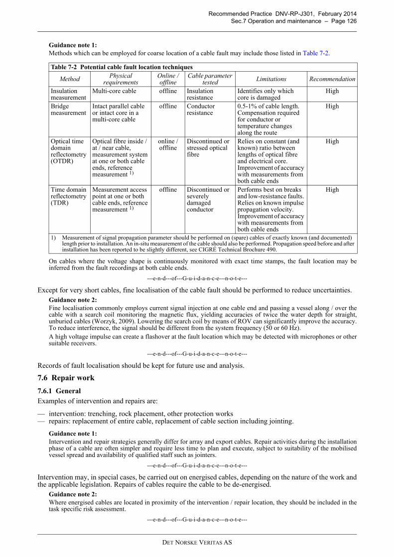
Recommended Practice DNV-RP-J301, February 2014
Sec.7 Operation and maintenance – Page 126
Guidance note 1:
Methods which can be employed for coarse location of a cable fault may include those listed in Table 7-2.
On cables where the voltage shape is continuously monitored with exact time stamps, the fault location may beinferred from the fault recordings at both cable ends.
---e-n-d---of---G-u-i-d-a-n-c-e---n-o-t-e---
Except for very short cables, fine localisation of the cable fault should be performed to reduce uncertainties.Guidance note 2:
Fine localisation commonly employs current signal injection at one cable end and passing a vessel along / over thecable with a search coil monitoring the magnetic flux, yielding accuracies of twice the water depth for straight,unburied cables (Worzyk, 2009). Lowering the search coil by means of ROV can significantly improve the accuracy.To reduce interference, the signal should be different from the system frequency (50 or 60 Hz).A high voltage impulse can create a flashover at the fault location which may be detected with microphones or othersuitable receivers.
---e-n-d---of---G-u-i-d-a-n-c-e---n-o-t-e---
Records of fault localisation should be kept for future use and analysis.
7.6 Repair work
7.6.1 General
Examples of intervention and repairs are:
— intervention: trenching, rock placement, other protection works— repairs: replacement of entire cable, replacement of cable section including jointing.
Guidance note 1:
Intervention and repair strategies generally differ for array and export cables. Repair activities during the installationphase of a cable are often simpler and require less time to plan and execute, subject to suitability of the mobilisedvessel spread and availability of qualified staff such as jointers.
---e-n-d---of---G-u-i-d-a-n-c-e---n-o-t-e---
Intervention may, in special cases, be carried out on energised cables, depending on the nature of the work andthe applicable legislation. Repairs of cables require the cable to be de-energised.
Guidance note 2:
Where energised cables are located in proximity of the intervention / repair location, they should be included in thetask specific risk assessment.
---e-n-d---of---G-u-i-d-a-n-c-e---n-o-t-e---
Table 7-2 Potential cable fault location techniques
MethodPhysical
requirementsOnline / offline
Cable parameter tested
Limitations Recommendation
Insulation measurement
Multi-core cable offline Insulation resistance
Identifies only which core is damaged
High
Bridge measurement
Intact parallel cable or intact core in a multi-core cable
offline Conductor resistance
0.5-1% of cable length. Compensation required for conductor or temperature changes along the route
High
Optical time domain reflectometry (OTDR)
Optical fibre inside / at / near cable, measurement system at one or both cable ends, reference measurement 1)
online / offline
Discontinued or stressed optical fibre
Relies on constant (and known) ratio between lengths of optical fibre and electrical core. Improvement of accuracy with measurements from both cable ends
High
Time domain reflectometry (TDR)
Measurement access point at one or both cable ends, reference measurement 1)
offline Discontinued or severely damaged conductor
Performs best on breaks and low-resistance faults. Relies on known impulse propagation velocity. Improvement of accuracy with measurements from both cable ends
High
1) Measurement of signal propagation parameter should be performed on (spare) cables of exactly known (and documented) length prior to installation. An in-situ measurement of the cable should also be performed. Propagation speed before and after installation has been reported to be slightly different, see CIGRÉ Technical Brochure 490.
DET NORSKE VERITAS AS
Recommended Practice DNV-RP-J301, February 2014
Sec.7 Operation and maintenance – Page 127
All repairs shall be carried out by qualified personnel in accordance with agreed specifications and proceduresdefined for the cable.
Spare cable, repair parts and material such as jointing kits shall be stored suitably protected to preventdeterioration or damage. Where applicable, expiration dates should be clearly marked on the parts and material.
In specific circumstances, longer term storage of spare cable on or in the seabed (“wet storage”) may beallowable.
Guidance note 3:
When planning wet storage, the risk of damage by a third party should be considered, with burial being a potentialmitigation measure. Cables may also get damaged during recovery. Cables should be pre-rigged for retrieval.
---e-n-d---of---G-u-i-d-a-n-c-e---n-o-t-e---
7.6.2 Repair planning
Operational limiting conditions with regard to the sea-state, current and vessel movements shall be established.The level of uncertainty in weather forecast shall be taken into account, see [6.1].
The position of the repair shall be verified prior to start of operations. A survey shall be performed to establishthat the location is free of obstructions and that the seabed conditions will permit the repair to be performed asspecified.
Guidance note:
The planned repair bight may lie outside the previously surveyed corridor and thereby require additional inspectionor survey work prior to repair execution.De-burial of the cable should be adequately planned, in particular in areas where deep burial was accomplished orwhere mobile sediments led to significant accretion on top of the cable. In addition, artificial reefs that have formedin the meantime, e.g. on installed rock, will be disturbed and may require specific considerations.
---e-n-d---of---G-u-i-d-a-n-c-e---n-o-t-e---
Potential anchoring requirements and the laydown of the repaired cable shall be carefully planned, see also[4.5.2]. The repair joint should, if possible, be laid in line with the cable, not within an arc.
Arrangements and equipment for lifting and lowering of the repair bight shall be analysed to determine thecritical parameters and limiting criteria for the operation. Critical parameters / limiting criteria shall bemonitored continuously.
7.6.3 Repair execution
If the damaged cable is of a short length only (e.g. array cable between turbines), a complete replacement ofthe cable may be the most economical solution. This involves securing the cable at one end and recovering itfrom the seabed after (or during) partial or complete de-burial. Installation of a new cable follows the steps ofcable laying and burial (Sec.6).
If the damage of a cable is located close to a termination point, then a repair requiring only one inline joint maybe feasible. In this case the cable section between termination point and damage location is cut out and a newsection is jointed in. After laydown of the inline joint, the cable is laid and pulled to the termination point as asecond-end pull operation.
If a cable repair is to be carried out further away from either cable end and assuming that the cable ([7.5.2]) andthe fault ([7.5.3]) have been located with sufficient accuracy, a repair sequence typically involves the followingsteps:
— de-burial of the cable along a section of sufficient length which is to be recovered— cutting of the cable at the seabed (e.g. by ROV)— recovery of first cable end and attaching a buoy to the second end— removal of impaired part from the first cable end, jointing of spare cable section to first end— laydown of first joint (as inline joint)— recovery of second cable end, removal of impaired part, jointing with spare cable end— laydown of second joint (typically as an omega repair bight; joint deployed first, then the quadrant with the
repair bight crown)— protection of laid cable, e.g. by burial or rock placement.
Installation of joints shall be performed in accordance with the manufacturer’s procedure (see [6.4.3]). Duringall handling, lifting and lowering into the final position, the cable and the joint shall be protected againstmechanical damage (tension, bending, etc.). Bend stiffeners and/or bend restrictors used at either side of thecable joint should be approved by the cable manufacturer.
It shall be verified that the position of the repair bight is within the target area prior to departure of the vesselfrom site. The cable stability shall be ensured and adequate protection of the cable provided.
After completion of the repair, a survey of the cable on both sides of the repair area, and over a length sufficientto ensure that no damage has occurred, should be performed, see [6.8].
DET NORSKE VERITAS AS
Recommended Practice DNV-RP-J301, February 2014
Sec.7 Operation and maintenance – Page 128
All repairs shall be inspected and electrically tested by experienced and qualified personnel in accordance withagreed procedures. Testing personnel, equipment, methods, and acceptance criteria shall be agreed upon inaccordance with [6.9.2].
All intervention and repair works shall be documented.
7.7 Requalification
7.7.1 General
Requalification is a re-assessment of the design under changed design conditions.
Within the original design life, and without essential changes in the manner of use, the standard(s) under whichthe cable system was designed and built may apply when considering minor modifications or rectification ofdesign parameters exceeded during operation. For major modifications, see [7.7.2].
Guidance note:
For revision of qualification procedures of AC extruded underground cable systems, see CIGRÉ Technical Brochure303.
---e-n-d---of---G-u-i-d-a-n-c-e---n-o-t-e---
7.7.2 Change of design criteria
A requalification may be triggered by a change in the original design basis, by not fulfilling the design basis,or by mistakes / shortcomings having been discovered during normal or abnormal operation. Possible causesmay be:
— change of the premises, e.g. environmental loads, scour— change of operational parameters or utilisation (voltage, current, power, temperature)— deterioration mechanisms having exceeded the original assumptions, e.g. excessive scour— extended service life— discovered damage, e.g. to cable protection.
All relevant deterioration and damage mechanisms should be evaluated. Typical mechanisms includeinsulation deterioration, accidental loads, fatigue, development of free spans, erosion and settlement.
Accumulated damage experienced prior to the requalification should be included in the evaluation.
The parameters that trigger the requalification and the implication of changes in these parameters on differentdesign conditions should be clearly identified and documented. The revised design conditions should form thebasis for a re-assessment of the relevant parts of the cable system design according to Sec.2, Sec.3 and Sec.4.
7.7.3 System test
An inspection of the cable system according to [7.3.2] should be considered. System testing may be requiredwhen:
— the original cable test or system test does not satisfy requirements at the new operating parameters— a significant part of the cable has not been tested before, e.g. new cable sections as part of a modification
or repair campaign.
Guidance note:
Testing of aged cables with voltages higher than nominal can increase the risk of insulation breakdown.
---e-n-d---of---G-u-i-d-a-n-c-e---n-o-t-e---
DET NORSKE VERITAS AS
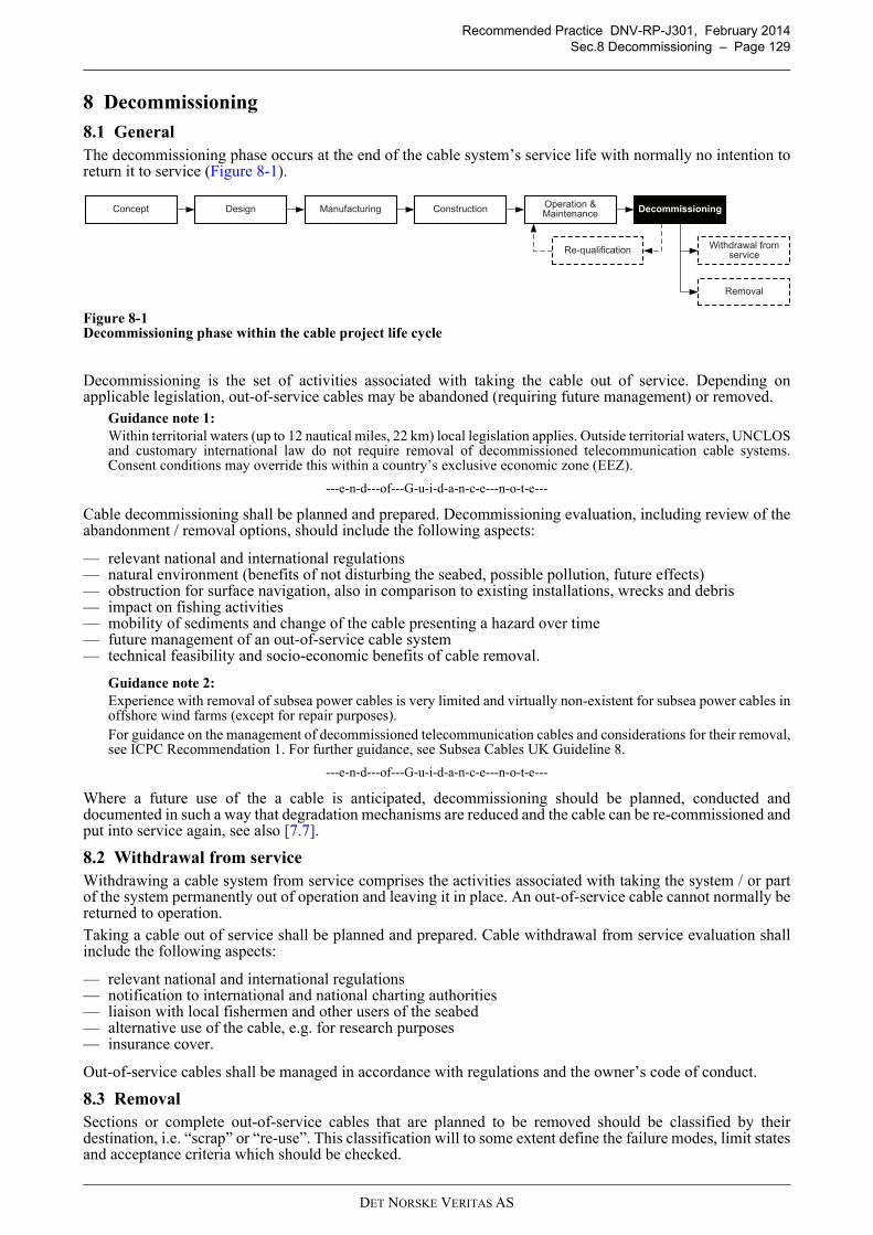
Recommended Practice DNV-RP-J301, February 2014
Sec.8 Decommissioning – Page 129
8 Decommissioning
8.1 General
The decommissioning phase occurs at the end of the cable system’s service life with normally no intention toreturn it to service (Figure 8-1).
Figure 8-1Decommissioning phase within the cable project life cycle
Decommissioning is the set of activities associated with taking the cable out of service. Depending onapplicable legislation, out-of-service cables may be abandoned (requiring future management) or removed.
Guidance note 1:
Within territorial waters (up to 12 nautical miles, 22 km) local legislation applies. Outside territorial waters, UNCLOSand customary international law do not require removal of decommissioned telecommunication cable systems.Consent conditions may override this within a country’s exclusive economic zone (EEZ).
---e-n-d---of---G-u-i-d-a-n-c-e---n-o-t-e---
Cable decommissioning shall be planned and prepared. Decommissioning evaluation, including review of theabandonment / removal options, should include the following aspects:
— relevant national and international regulations— natural environment (benefits of not disturbing the seabed, possible pollution, future effects)— obstruction for surface navigation, also in comparison to existing installations, wrecks and debris— impact on fishing activities— mobility of sediments and change of the cable presenting a hazard over time— future management of an out-of-service cable system— technical feasibility and socio-economic benefits of cable removal.
Guidance note 2:
Experience with removal of subsea power cables is very limited and virtually non-existent for subsea power cables inoffshore wind farms (except for repair purposes).For guidance on the management of decommissioned telecommunication cables and considerations for their removal,see ICPC Recommendation 1. For further guidance, see Subsea Cables UK Guideline 8.
---e-n-d---of---G-u-i-d-a-n-c-e---n-o-t-e---
Where a future use of the a cable is anticipated, decommissioning should be planned, conducted anddocumented in such a way that degradation mechanisms are reduced and the cable can be re-commissioned andput into service again, see also [7.7].
8.2 Withdrawal from service
Withdrawing a cable system from service comprises the activities associated with taking the system / or partof the system permanently out of operation and leaving it in place. An out-of-service cable cannot normally bereturned to operation.
Taking a cable out of service shall be planned and prepared. Cable withdrawal from service evaluation shallinclude the following aspects:
— relevant national and international regulations— notification to international and national charting authorities— liaison with local fishermen and other users of the seabed— alternative use of the cable, e.g. for research purposes— insurance cover.
Out-of-service cables shall be managed in accordance with regulations and the owner’s code of conduct.
8.3 Removal
Sections or complete out-of-service cables that are planned to be removed should be classified by theirdestination, i.e. “scrap” or “re-use”. This classification will to some extent define the failure modes, limit statesand acceptance criteria which should be checked.
DesignConceptOperation & Maintenance
Construction Decommissioning
Withdrawal from service
Removal
Re-qualification
Manufacturing
DET NORSKE VERITAS AS
Recommended Practice DNV-RP-J301, February 2014
Sec.8 Decommissioning – Page 130
Agreements covering the decommissioning phase should make provisions for the recovery of (at least) limitedlengths of cable. The agreement should consider future requests for partial cable removal from
— developers of new cable or pipeline systems, to avoid a crossing— developers of new offshore units, to avoid a cable in the immediate vicinity— other users of the sea, to avoid interference with planned activities.
Cable removal shall be planned and prepared. Cable removal evaluation should include the following aspects:
— relevant national and international regulations— health and safety of personnel— minimisation of environmental impact— competence, experience and insurance cover of salvage party— scrap value of materials, in particular metals— treatment and documentation of cable segments left in the seabed.
Guidance note 1:
For guidance on planning and execution of marine operations for removal of offshore objects, see DNV-RP-H102.
---e-n-d---of---G-u-i-d-a-n-c-e---n-o-t-e---
Partial removal of cable should not leave the remaining cable system in a more hazardous condition than priorto removal.
Guidance note 2:
Cable ends require specific considerations. Weighing down and burial may be required.
---e-n-d---of---G-u-i-d-a-n-c-e---n-o-t-e---
DET NORSKE VERITAS AS
Recommended Practice DNV-RP-J301, February 2014
Sec.9 Documentation – Page 131
9 Documentation
9.1 General
This section specifies the minimum requirements to documentation needed for design, manufacturing, storage,load-out, transportation, installation, commissioning, operation, maintenance and decommissioning of a powercable system.
A design, manufacturing, installation documentation summary should be established with its main objectivebeing to provide the stakeholder organisation with a summary of the most relevant data from those projectphases. The preparation of the documentation summary should be carried out in parallel with, and as anintegrated part, of the design, manufacturing and installation phases of the project.
Guidance note 1:
A common language, e.g. English, should be used for all documentation.Symbols used should be explained, or reference to a standard code should be given. Measurement units defined byInternational System of Units (SI) should be used unless otherwise agreed.
---e-n-d---of---G-u-i-d-a-n-c-e---n-o-t-e---
Important documents which should be available at the specified times include the following:
— design basis and functional specifications - prior to design— design calculations, reports, drawings - prior to manufacture— reports of prequalification tests performed on the entire cable system - prior to manufacture— manufacturing quality plan - prior to manufacture— manufacturing and testing specification - prior to manufacture— as-manufactured documentation and test reports - with supplied cable, accessories, offshore unit— installation plan and method statements - prior to installation— as-built documentation and test reports - after installation— operations documentation - prior to operations start.
For the design, manufacturing and installation phases, all required documentation should be reflected in amaster document register which is kept up to date.
Guidance note 2:
Unique revision numbers should be allocated to all issues of a document, including the first issue. For documents withmultiple sheets, the revision number should be the same for all sheets. Updated documents should be marked toidentify the revised parts.
---e-n-d---of---G-u-i-d-a-n-c-e---n-o-t-e---
An in-service file containing all relevant data achieved during the operational phase of the cable system andwith the main objective to systemise information needed for integrity management should be established andmaintained for the whole service life.
The required documentation for all phases of the cable system’s lifetime should be submitted to the relevantparties for acceptance or information, as agreed or required.
An overview of documents which should be established is provided in [9.2]. Further documentationrequirements are contained within the individual sections of this recommended practice.
9.2 Documents
9.2.1 Concept development
The results of early concept development should typically be captured as follows:
— summary report and detailed analysis results including recommendations and supported by relevant maps,figures and tables.
— geo-referenced information database collated in a geographical information system (GIS).— data presentations in the form of charts, including the proposed cable route together with pertinent features.
The reporting on the cable route surveys should contain detailed information on all aspects of the cable project,including, but not limited to the following (see also [3.3.2]):
— analysis of project area / route, geology, terrestrial and marine conditions, environmental impact, thirdparty activities, regulatory requirements
— preliminary route assessment and route recommendations— preliminary recommendations for cable protection design.
The report should also show the results of the surveys on accurate route maps and alignments, at a scalecommensurate with required use. The route alignment sheets should include cable route, bathymetry, seabedfeatures, subsea infrastructure, navigational aids / fairways, surface geology and interpreted subsurfacegeology, location of geotechnical investigation points and other relevant features.
DET NORSKE VERITAS AS
Recommended Practice DNV-RP-J301, February 2014
Sec.9 Documentation – Page 132
Output from the concept development phase should typically be captured in:
— project description, including GIS database— functional requirements— design basis.
9.2.2 Design basis
Typical content of the design basis is listed in the following:
— system overview:
— cable system overview including general arrangements and key operational parameters— project stakeholders with responsibilities, interfaces, communication lines— general project plan and schedule.
— terms of reference:
— reference to detailed project description and functional requirements (including design and service life)— health and safety, environmental and quality objectives— hierarchy of applicable codes, standards and regulations— use of SI system, coordinate system and references— horizontal and vertical reference data, coordinate system— general design approach, methods to be used.
— site conditions (design values):
— third party activities, restricted areas, obstructions ([3.3.4])— topographic and bathymetric conditions ([3.3.5], [3.4])— geological conditions, morphological aspects ([3.3.5], [3.4])— atmospheric and marine conditions ([3.3.6])— environmental constraints, permit and license restrictions ([3.3.7])— design loads and load combinations.
Guidance note:
The description of site conditions forms a major part of the design basis. Measured or estimated values should not besimply reported, but those values to be applied in the design (commonly employing a level of conservatism) shouldbe defined.
---e-n-d---of---G-u-i-d-a-n-c-e---n-o-t-e---
— technical interfaces:
— coordinates of interface points, principal cable routing and lengths— description / drawings of offshore units and landfall area— mechanical interface conditions (e.g. cable joint or switchgear)— electrical interface conditions— optical interface conditions.
— manufacturing and storage aspects:
— manufacturability conditions— material properties and quality, as applicable— cable sizing and handling data— testing requirements— storage (time, conditions).
— load-out, transportation and installation aspects:
— access to site (onshore, offshore)— basic vessel spread capabilities and motion characteristics— installability conditions, sequencing, scope.
— operation and maintenance aspects:
— monitoring and inspection capabilities— acceptable limits for free spans, external aggression— maintainability conditions, acceptable frequency and type of intervention— repair-ability conditions.
DET NORSKE VERITAS AS

Recommended Practice DNV-RP-J301, February 2014
Sec.9 Documentation – Page 133
— decommissioning aspects:
— traceability of buried cable— recoverability of buried / protected cable.
More detailed / specifically scoped design basis (sub-) documents may be required for certain design aspects.
9.2.3 Design
Design documentation suitable for third party verification shall be produced. It may include, but not be limitedto, the following:
— systematic review of hazards, risk register, contingency measures— materials selection— electrical and thermal calculations— cable system design details; including cable, joints, terminations— cable route design— cable end point interface design— cable installation analysis— general method statements for storage, load-out, transport, installation, commissioning, operation,
maintenance, repair and decommissioning.
Guidance note:
A method statement is a written plan of work tasks to be carried out, documenting a ‘safe system to work’. It is animportant means of controlling the health and safety risk, e.g. following a risk assessment. A procedure is commonlya more specific, step by step description of work steps.
---e-n-d---of---G-u-i-d-a-n-c-e---n-o-t-e---
GIS information and drawings provided for the manufacturing of components or installation of the cablesystem should include, but not be limited to:
— cable route drawings including information on topology, seabed properties, existing and futureinfrastructure, shipping lanes, etc.
— alignment sheets— infrastructure crossings— offshore unit layout with cable path and details of interfaces— other components within the cable system (joints, terminations, etc.)— cable protection (burial, non-burial protection)— land ownership details.
9.2.4 Manufacturing
The documentation to be submitted for review prior to start of manufacturing should include, but not be limited to:
— quality plan— manufacturer’s quality system manual— manufacturing procedure including test requirements and acceptance criteria— electrical / thermal / mechanical calculations demonstrating the suitability of the component— component specifications and drawings.
The as-built documentation to be submitted after manufacturing may include, but not be limited to:
— quality control procedures— inspection and test plan— traceability procedure— material certificates— equipment calibration certificates / reports— component specifications and as-built drawings— test reports, including non-conformity reports— storage, handling and installation procedures— release certificates.
Guidance note:
For a more detailed cable specification template, see App.B. Cables should also be supplied with informationidentifying the position of power core joints along the length of the cable so these can be handled correctly duringtransport and installation.Other components for which specifications / manufacturing documentation should be submitted include joints,terminations, cable end caps (short-term, long-term), hang-off modules, pulling heads / stockings, etc.
---e-n-d---of---G-u-i-d-a-n-c-e---n-o-t-e---
DET NORSKE VERITAS AS
Recommended Practice DNV-RP-J301, February 2014
Sec.9 Documentation – Page 134
9.2.5 Installation
9.2.5.1 Documentation before installation
An installation manual shall be produced, which is defined as a document or collection of documents requiredfor performing the project specific installation work including normal and contingency operations andacceptance criteria.
Guidance note 1:
The installation manual is prepared in order to demonstrate that methods and equipment used by the installer will meetspecified requirements and that the results can be verified. The installation manual will hence include all factors thatinfluence quality, reliability and safety of the installation work in normal and contingency situations, and will addressall installation steps, including examinations and check points. The manual will reflect the results of the riskmanagement studies performed for the installation and will state requirements for the parameters to be controlled andthe allowable range of parameter variation during the installation.
---e-n-d---of---G-u-i-d-a-n-c-e---n-o-t-e---
The installation manual shall contain the applicable procedures and corresponding drawings and should besubmitted for review prior to start of installation.
Guidance note 2:
Typically a procedure describes the following:
— purpose and scope of activity— responsibilities— materials, equipment and documents to be used— how the activity is performed in order to meet specified requirements and acceptance criteria— how the activity is controlled and documented.
---e-n-d---of---G-u-i-d-a-n-c-e---n-o-t-e---
Typical procedures include, but are not limited to, the following:
General:
— risk management plan— hazard identification (HAZID) studies, hazard and operability (HAZOP) studies, failure mode and effect
analyses (FMEA)— simultaneous operations— diver intervention, if applicable— contingency (e.g. failure of positioning system) and emergency planning— inspection and test plan— qualifications and competence for personnel.
Cable route preparations:
— route survey— route clearance— route preparations— pre-lay grapnel run.
Cable logistics:
— cable storage— cable load-out— cable transport— cable trans-spooling, if applicable.
Cable installation:
— cable installation analysis— cable laying and catenary management— cable pull-in preparation and cable pull-in— cable protection and burial— cable crossing, if applicable— abandonment and recovery (A&R), ‘wet storage’— cable jointing— cable repair.
DET NORSKE VERITAS AS
Recommended Practice DNV-RP-J301, February 2014
Sec.9 Documentation – Page 135
Guidance note 3:
Detailed instructions will be required for more complex operations, e.g. cable overboarding, cable pull-in or cablerecovery.
---e-n-d---of---G-u-i-d-a-n-c-e---n-o-t-e---
Landfall:
— landfall site preparation— open-cut trenching— horizontal direction drilling and conduit installation— cable pull-in preparation and cable pull-in.
Commissioning:
— cable termination— cable system testing.
Marine logistics:
— cable installation vessel suitability analysis, motion analysis— vessel mobilisation— navigation and positioning, including anchors / anchor handling and/or dynamic positioning, dynamic
positioning trials— access to and egress from offshore units— operational limiting conditions.
9.2.5.2 Documentation during installation
Construction activities should be documented in a consistent way. The scope, content and format of the GISinformation and documentation should be discussed and contractually agreed prior to the commencement ofon-site works. Typically, the reporting should cover:
— project / activity overview— vessels, equipment used— health, safety and environmental performance— daily progress report, log of events, non-conformities, variation orders, incident investigations (if applicable)— position (as-built) data (x, y, z)— testing information according to inspection test plan.
The narrative should be supplemented by survey maps and, where applicable, video recordings (e.g. of cableinterface with offshore unit).
Guidance note:
There may be a need to prepare preliminary as-built information during the installation operations, e.g. after cableinstallation to demonstrate that the cable is correctly pulled into the offshore unit.
---e-n-d---of---G-u-i-d-a-n-c-e---n-o-t-e---
9.2.5.3 Documentation after installation
For guidance on reporting of as-built surveys, see [6.8.2].
The as-built documentation to be submitted after installation and commissioning should include, but not belimited to:
— survey reports— installation, commissioning and test reports— updated GIS information and drawings.
The location of cables shall be reported to international and national authorities for the purpose of updatingnavigation charts.
Awareness of the cables (and rock berms, etc.) should be increased by inclusion of cables in freely available“cable awareness charts” and proactive liaison with stakeholder groups such as:
— hydrographic offices / authorities— port and local authorities— environmental authorities— military authorities— commercial and scientific organisations (e.g. pipeline owners, dredgers)— fishing industry— maintenance parties.
DET NORSKE VERITAS AS
Recommended Practice DNV-RP-J301, February 2014
Sec.9 Documentation – Page 136
9.2.6 Operation and maintenance
As a minimum, the following documentation shall be established:
— cable system integrity management strategy covering operation, inspection and maintenance— operational envelope, parameters, constraints, decisions for the operation of the cable system— emergency response strategy— repair strategy.
In order to maintain the integrity of the cable system, the documentation made available during the operationalphase should include, but not be limited to:
— personnel training and qualifications records— history of cable system operation with reference to events which may have significance to design and safety— installation condition data as necessary for understanding cable system design and configuration, e.g.
previous survey reports, as-laid / as-built installation data and test reports— inspection and maintenance procedures— inspection and maintenance schedules and records of their results.
The in-service file should include, but not be limited to:
— operational data— results and conclusions from the in-service inspections— accidental events and damages to the cable system— intervention, modification and repair.
In case of damage and repair, the documentation prepared should include, but not be limited to:
— description of the damage to the cable system or components with due reference to location, type, extent ofdamage
— plans and full particulars of repairs, modifications and replacements, including contingency measures— further documentation with respect to particular repair, modification and replacement, in line with those for
the installation phase.
Maintenance of complete files of all relevant documentation during the service life of the cable system is theresponsibility of the cable system operator.
9.2.7 Decommissioning
Records of a cable system withdrawn from service shall be available and should include, but not be limited to:
— details of out-of-service cable on land including route maps, the depth of burial and its location relative tosurface features
— details of out-of-service cables offshore, including navigation charts showing the cable route.
DET NORSKE VERITAS AS
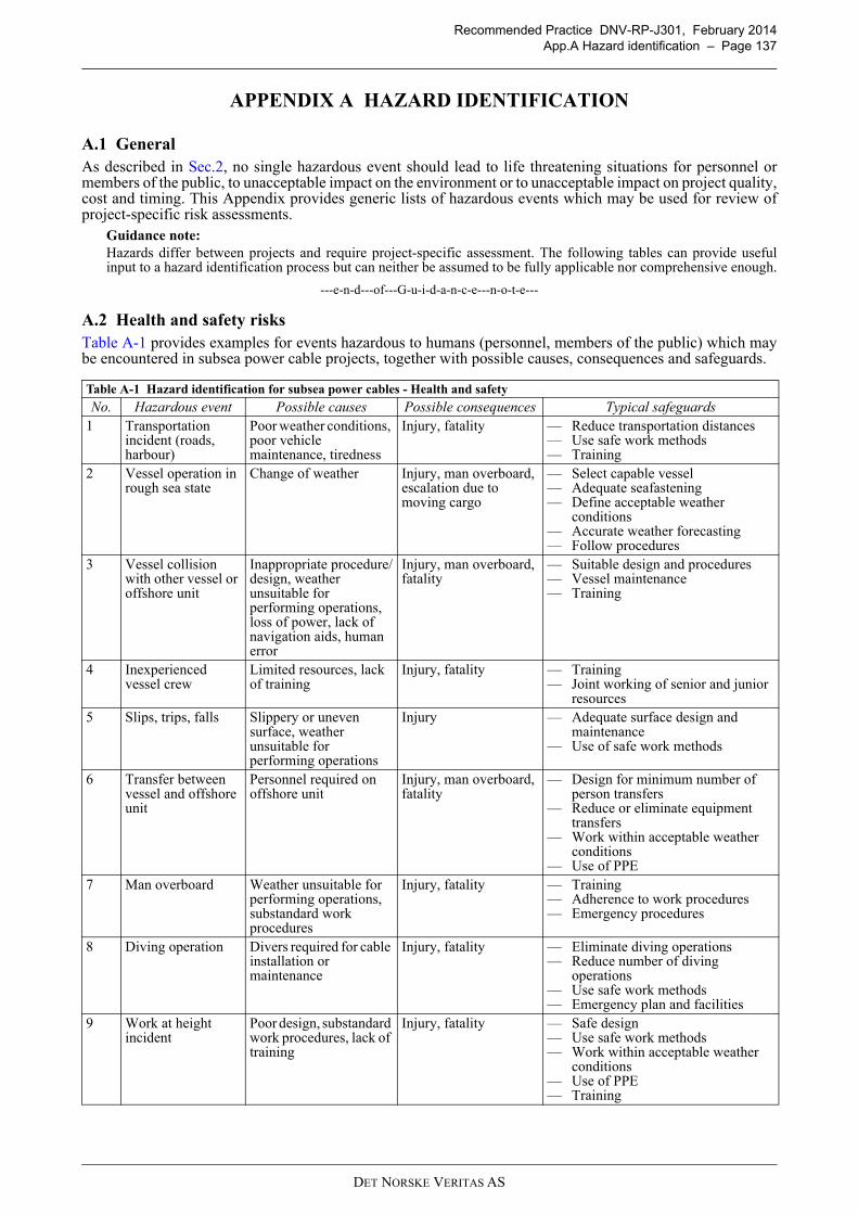
Recommended Practice DNV-RP-J301, February 2014
App.A Hazard identification – Page 137
APPENDIX A HAZARD IDENTIFICATION
A.1 General
As described in Sec.2, no single hazardous event should lead to life threatening situations for personnel ormembers of the public, to unacceptable impact on the environment or to unacceptable impact on project quality,cost and timing. This Appendix provides generic lists of hazardous events which may be used for review ofproject-specific risk assessments.
Guidance note:
Hazards differ between projects and require project-specific assessment. The following tables can provide usefulinput to a hazard identification process but can neither be assumed to be fully applicable nor comprehensive enough.
---e-n-d---of---G-u-i-d-a-n-c-e---n-o-t-e---
A.2 Health and safety risks
Table A-1 provides examples for events hazardous to humans (personnel, members of the public) which maybe encountered in subsea power cable projects, together with possible causes, consequences and safeguards.
Table A-1 Hazard identification for subsea power cables - Health and safety
No. Hazardous event Possible causes Possible consequences Typical safeguards
1 Transportation incident (roads, harbour)
Poor weather conditions, poor vehicle maintenance, tiredness
Injury, fatality — Reduce transportation distances— Use safe work methods— Training
2 Vessel operation in rough sea state
Change of weather Injury, man overboard, escalation due to moving cargo
— Select capable vessel— Adequate seafastening— Define acceptable weather
conditions— Accurate weather forecasting— Follow procedures
3 Vessel collision with other vessel or offshore unit
Inappropriate procedure/design, weather unsuitable for performing operations, loss of power, lack of navigation aids, human error
Injury, man overboard, fatality
— Suitable design and procedures— Vessel maintenance— Training
4 Inexperienced vessel crew
Limited resources, lack of training
Injury, fatality — Training— Joint working of senior and junior
resources5 Slips, trips, falls Slippery or uneven
surface, weather unsuitable for performing operations
Injury — Adequate surface design and maintenance
— Use of safe work methods
6 Transfer between vessel and offshore unit
Personnel required on offshore unit
Injury, man overboard, fatality
— Design for minimum number of person transfers
— Reduce or eliminate equipment transfers
— Work within acceptable weather conditions
— Use of PPE7 Man overboard Weather unsuitable for
performing operations, substandard work procedures
Injury, fatality — Training— Adherence to work procedures— Emergency procedures
8 Diving operation Divers required for cable installation or maintenance
Injury, fatality — Eliminate diving operations— Reduce number of diving
operations— Use safe work methods— Emergency plan and facilities
9 Work at height incident
Poor design, substandard work procedures, lack of training
Injury, fatality — Safe design— Use safe work methods— Work within acceptable weather
conditions — Use of PPE— Training
DET NORSKE VERITAS AS
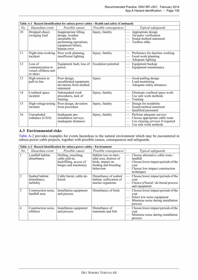
Recommended Practice DNV-RP-J301, February 2014
App.A Hazard identification – Page 138
A.3 Environmental risks
Table A-2 provides examples for events hazardous to the natural environment which may be encountered insubsea power cable projects, together with possible causes, consequences and safeguards.
10 Dropped object, swinging load
Inappropriate lifting design, weather unsuitable for performing operations, equipment failure, human error
Injury, fatality — Appropriate design— 3rd party verification— Sound method statement— Toolbox talks
11 Night-time working incident
Poor work planning, insufficient lighting
Injury, fatality — Preference for daytime working— Good work planning— Adequate lighting
12 Loss of communication to vessel, offshore unit or shore
Equipment fault, loss of power
Escalation potential — Equipment backup— Equipment maintenance
13 High tension in pull-in line
Poor design, uncalibrated equipment, deviations from method statement
Injury — Good pulling design— Load monitoring— Adequate safety distances
14 Confined space incident
Substandard work procedures, lack of training
Injury, fatality — Eliminate confined space work— Use safe work methods— Training
15 High voltage testing incident
Poor design, deviation from procedure
Injury, fatality — Design for testability— Sound method statement— Qualified personnel
16 Unexploded ordnance (UXO)
Inadequate pre-installation surveys, inadequate distances
Injury, fatality — Perform adequate surveys— Choose appropriate cable route— Use clearing services if required— Use safe work methods
Table A-2 Hazard identification for subsea power cables - Environment
No. Hazardous event Possible causes Possible consequences Typical safeguards
1 Landfall habitat disturbance
Drilling, trenching, cable pull-in, backfilling, access of barges and machinery
Habitat loss in inter-tidal area, distress of birds, impact on feeding and breeding behaviour
— Choose alternative cable route / landfall
— Choose lower impact periods of the year
— Choose low-impact construction techniques
2 Seabed habitat disturbance, turbidity
Cable burial, cable de-burial
Disturbance of seabed habitat, suffocation of marine organisms
— Choose lower impact periods of the year
— Choice of burial / de-burial process and equipment
3 Construction noise, landfall area
Installation equipment and process
Disturbance of birds — Choose lower impact periods of the year
— Select low noise equipment— Minimise noise during installation
process4 Construction noise,
offshoreInstallation equipment and process
Disturbance of mammals and fish
— Choose lower impact periods of the year
— Minimise noise during installation process
Table A-1 Hazard identification for subsea power cables - Health and safety (Continued)
No. Hazardous event Possible causes Possible consequences Typical safeguards
DET NORSKE VERITAS AS
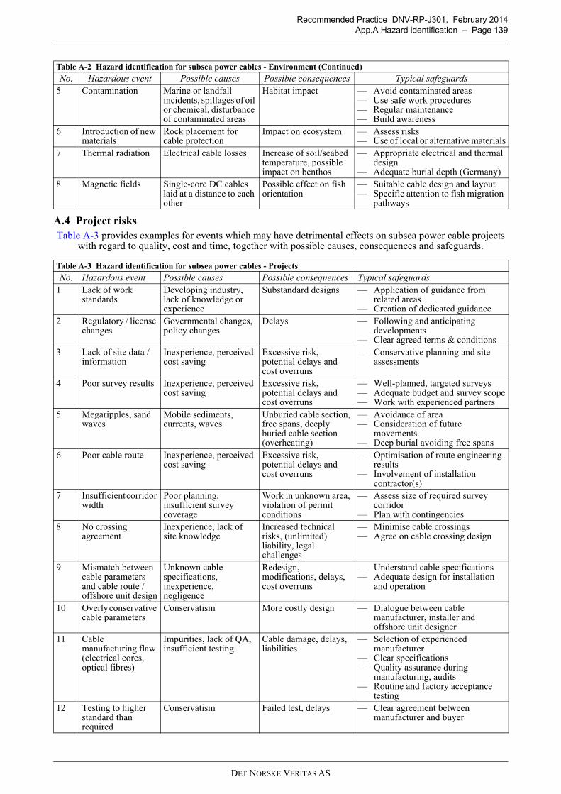
Recommended Practice DNV-RP-J301, February 2014
App.A Hazard identification – Page 139
A.4 Project risks
Table A-3 provides examples for events which may have detrimental effects on subsea power cable projects with regard to quality, cost and time, together with possible causes, consequences and safeguards.
5 Contamination Marine or landfall incidents, spillages of oil or chemical, disturbance of contaminated areas
Habitat impact — Avoid contaminated areas— Use safe work procedures— Regular maintenance— Build awareness
6 Introduction of new materials
Rock placement for cable protection
Impact on ecosystem — Assess risks— Use of local or alternative materials
7 Thermal radiation Electrical cable losses Increase of soil/seabed temperature, possible impact on benthos
— Appropriate electrical and thermal design
— Adequate burial depth (Germany)8 Magnetic fields Single-core DC cables
laid at a distance to each other
Possible effect on fish orientation
— Suitable cable design and layout— Specific attention to fish migration
pathways
Table A-3 Hazard identification for subsea power cables - Projects
No. Hazardous event Possible causes Possible consequences Typical safeguards
1 Lack of work standards
Developing industry, lack of knowledge or experience
Substandard designs — Application of guidance from related areas
— Creation of dedicated guidance2 Regulatory / license
changesGovernmental changes, policy changes
Delays — Following and anticipating developments
— Clear agreed terms & conditions3 Lack of site data /
informationInexperience, perceived cost saving
Excessive risk, potential delays and cost overruns
— Conservative planning and site assessments
4 Poor survey results Inexperience, perceived cost saving
Excessive risk, potential delays and cost overruns
— Well-planned, targeted surveys— Adequate budget and survey scope— Work with experienced partners
5 Megaripples, sand waves
Mobile sediments, currents, waves
Unburied cable section, free spans, deeply buried cable section (overheating)
— Avoidance of area— Consideration of future
movements— Deep burial avoiding free spans
6 Poor cable route Inexperience, perceived cost saving
Excessive risk, potential delays and cost overruns
— Optimisation of route engineering results
— Involvement of installation contractor(s)
7 Insufficient corridor width
Poor planning, insufficient survey coverage
Work in unknown area, violation of permit conditions
— Assess size of required survey corridor
— Plan with contingencies8 No crossing
agreementInexperience, lack of site knowledge
Increased technical risks, (unlimited) liability, legal challenges
— Minimise cable crossings— Agree on cable crossing design
9 Mismatch between cable parameters and cable route / offshore unit design
Unknown cable specifications, inexperience, negligence
Redesign, modifications, delays, cost overruns
— Understand cable specifications— Adequate design for installation
and operation
10 Overly conservative cable parameters
Conservatism More costly design — Dialogue between cable manufacturer, installer and offshore unit designer
11 Cable manufacturing flaw (electrical cores, optical fibres)
Impurities, lack of QA, insufficient testing
Cable damage, delays, liabilities
— Selection of experienced manufacturer
— Clear specifications— Quality assurance during
manufacturing, audits— Routine and factory acceptance
testing12 Testing to higher
standard than required
Conservatism Failed test, delays — Clear agreement between manufacturer and buyer
Table A-2 Hazard identification for subsea power cables - Environment (Continued)
No. Hazardous event Possible causes Possible consequences Typical safeguards
DET NORSKE VERITAS AS
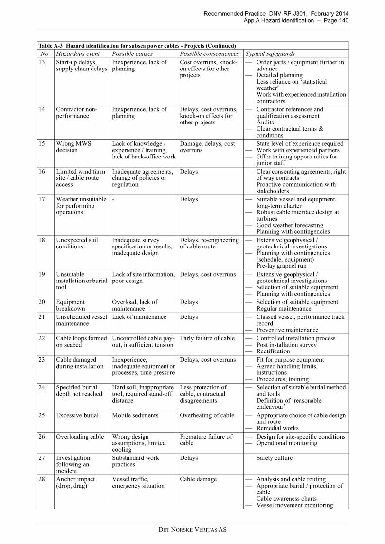
Recommended Practice DNV-RP-J301, February 2014
App.A Hazard identification – Page 140
13 Start-up delays, supply chain delays
Inexperience, lack of planning
Cost overruns, knock-on effects for other projects
— Order parts / equipment further in advance
— Detailed planning— Less reliance on ‘statistical
weather’— Work with experienced installation
contractors14 Contractor non-
performanceInexperience, lack of planning
Delays, cost overruns, knock-on effects for other projects
— Contractor references and qualification assessment
— Audits— Clear contractual terms &
conditions15 Wrong MWS
decisionLack of knowledge / experience / training, lack of back-office work
Damage, delays, cost overruns
— State level of experience required— Work with experienced partners— Offer training opportunities for
junior staff16 Limited wind farm
site / cable route access
Inadequate agreements, change of policies or regulation
Delays — Clear consenting agreements, right of way contracts
— Proactive communication with stakeholders
17 Weather unsuitable for performing operations
- Delays — Suitable vessel and equipment, long-term charter
— Robust cable interface design at turbines
— Good weather forecasting— Planning with contingencies
18 Unexpected soil conditions
Inadequate survey specification or results, inadequate design
Delays, re-engineering of cable route
— Extensive geophysical / geotechnical investigations
— Planning with contingencies (schedule, equipment)
— Pre-lay grapnel run19 Unsuitable
installation or burial tool
Lack of site information, poor design
Delays, cost overruns — Extensive geophysical / geotechnical investigations
— Selection of suitable equipment— Planning with contingencies
20 Equipment breakdown
Overload, lack of maintenance
Delays — Selection of suitable equipment— Regular maintenance
21 Unscheduled vessel maintenance
Lack of maintenance Delays — Classed vessel, performance track record
— Preventive maintenance22 Cable loops formed
on seabedUncontrolled cable pay-out, insufficient tension
Early failure of cable — Controlled installation process— Post installation survey— Rectification
23 Cable damaged during installation
Inexperience, inadequate equipment or processes, time pressure
Delays, cost overruns — Fit for purpose equipment— Agreed handling limits,
instructions— Procedures, training
24 Specified burial depth not reached
Hard soil, inappropriate tool, required stand-off distance
Less protection of cable, contractual disagreements
— Selection of suitable burial method and tools
— Definition of ‘reasonable endeavour’
25 Excessive burial Mobile sediments Overheating of cable — Appropriate choice of cable design and route
— Remedial works26 Overloading cable Wrong design
assumptions, limited cooling
Premature failure of cable
— Design for site-specific conditions— Operational monitoring
27 Investigation following an incident
Substandard work practices
Delays — Safety culture
28 Anchor impact (drop, drag)
Vessel traffic, emergency situation
Cable damage — Analysis and cable routing— Appropriate burial / protection of
cable— Cable awareness charts— Vessel movement monitoring
Table A-3 Hazard identification for subsea power cables - Projects (Continued)
No. Hazardous event Possible causes Possible consequences Typical safeguards
DET NORSKE VERITAS AS
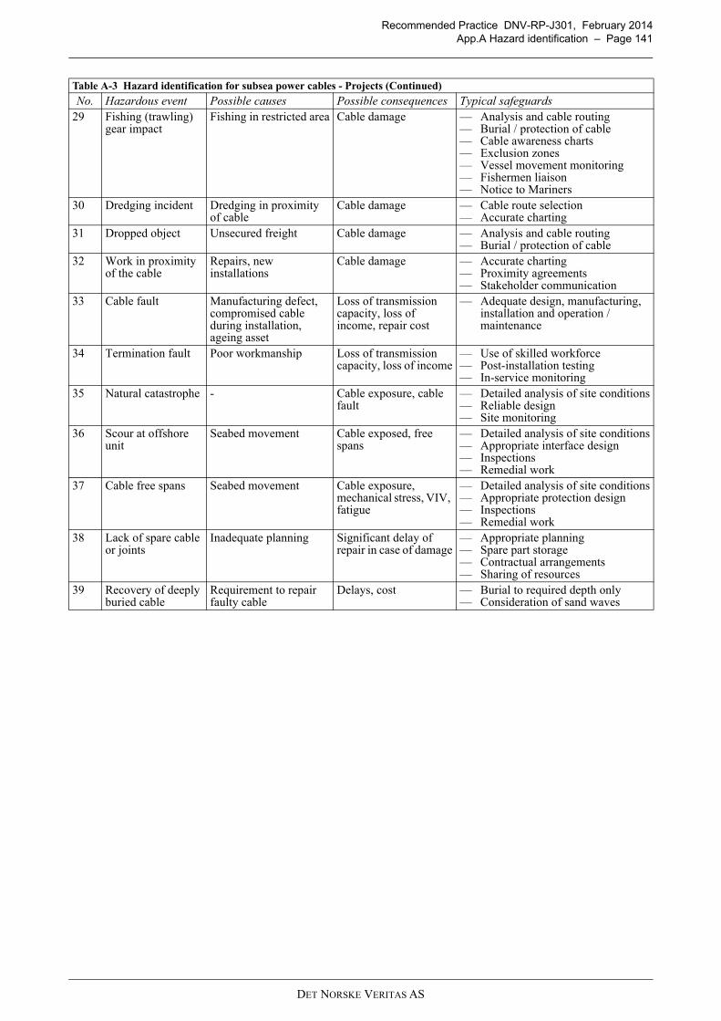
Recommended Practice DNV-RP-J301, February 2014
App.A Hazard identification – Page 141
29 Fishing (trawling) gear impact
Fishing in restricted area Cable damage — Analysis and cable routing— Burial / protection of cable— Cable awareness charts— Exclusion zones— Vessel movement monitoring— Fishermen liaison— Notice to Mariners
30 Dredging incident Dredging in proximity of cable
Cable damage — Cable route selection— Accurate charting
31 Dropped object Unsecured freight Cable damage — Analysis and cable routing— Burial / protection of cable
32 Work in proximity of the cable
Repairs, new installations
Cable damage — Accurate charting— Proximity agreements— Stakeholder communication
33 Cable fault Manufacturing defect, compromised cable during installation, ageing asset
Loss of transmission capacity, loss of income, repair cost
— Adequate design, manufacturing, installation and operation / maintenance
34 Termination fault Poor workmanship Loss of transmission capacity, loss of income
— Use of skilled workforce— Post-installation testing— In-service monitoring
35 Natural catastrophe - Cable exposure, cable fault
— Detailed analysis of site conditions— Reliable design— Site monitoring
36 Scour at offshore unit
Seabed movement Cable exposed, free spans
— Detailed analysis of site conditions— Appropriate interface design— Inspections— Remedial work
37 Cable free spans Seabed movement Cable exposure, mechanical stress, VIV, fatigue
— Detailed analysis of site conditions— Appropriate protection design— Inspections— Remedial work
38 Lack of spare cable or joints
Inadequate planning Significant delay of repair in case of damage
— Appropriate planning— Spare part storage— Contractual arrangements— Sharing of resources
39 Recovery of deeply buried cable
Requirement to repair faulty cable
Delays, cost — Burial to required depth only— Consideration of sand waves
Table A-3 Hazard identification for subsea power cables - Projects (Continued)
No. Hazardous event Possible causes Possible consequences Typical safeguards
DET NORSKE VERITAS AS
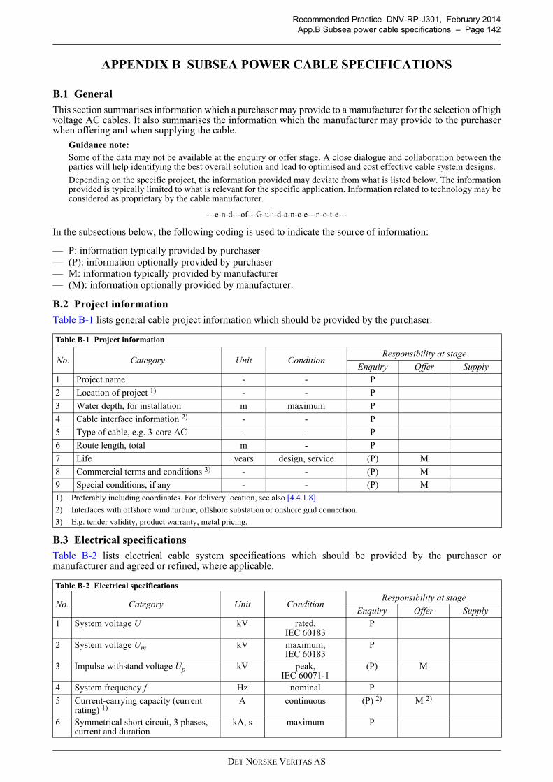
Recommended Practice DNV-RP-J301, February 2014
App.B Subsea power cable specifications – Page 142
APPENDIX B SUBSEA POWER CABLE SPECIFICATIONS
B.1 General
This section summarises information which a purchaser may provide to a manufacturer for the selection of highvoltage AC cables. It also summarises the information which the manufacturer may provide to the purchaserwhen offering and when supplying the cable.
Guidance note:
Some of the data may not be available at the enquiry or offer stage. A close dialogue and collaboration between theparties will help identifying the best overall solution and lead to optimised and cost effective cable system designs.
Depending on the specific project, the information provided may deviate from what is listed below. The informationprovided is typically limited to what is relevant for the specific application. Information related to technology may beconsidered as proprietary by the cable manufacturer.
---e-n-d---of---G-u-i-d-a-n-c-e---n-o-t-e---
In the subsections below, the following coding is used to indicate the source of information:
— P: information typically provided by purchaser— (P): information optionally provided by purchaser— M: information typically provided by manufacturer— (M): information optionally provided by manufacturer.
B.2 Project information
Table B-1 lists general cable project information which should be provided by the purchaser.
B.3 Electrical specifications
Table B-2 lists electrical cable system specifications which should be provided by the purchaser ormanufacturer and agreed or refined, where applicable.
Table B-1 Project information
No. Category Unit ConditionResponsibility at stage
Enquiry Offer Supply
1 Project name - - P
2 Location of project 1) - - P
3 Water depth, for installation m maximum P
4 Cable interface information 2) - - P
5 Type of cable, e.g. 3-core AC - - P
6 Route length, total m - P
7 Life years design, service (P) M
8 Commercial terms and conditions 3) - - (P) M
9 Special conditions, if any - - (P) M1) Preferably including coordinates. For delivery location, see also [4.4.1.8].
2) Interfaces with offshore wind turbine, offshore substation or onshore grid connection.
3) E.g. tender validity, product warranty, metal pricing.
Table B-2 Electrical specifications
No. Category Unit ConditionResponsibility at stage
Enquiry Offer Supply
1 System voltage U kV rated,IEC 60183
P
2 System voltage Um kV maximum,IEC 60183
P
3 Impulse withstand voltage Up kV peak,IEC 60071-1
(P) M
4 System frequency f Hz nominal P
5 Current-carrying capacity (current rating) 1)
A continuous (P) 2) M 2)
6 Symmetrical short circuit, 3 phases, current and duration
kA, s maximum P
DET NORSKE VERITAS AS
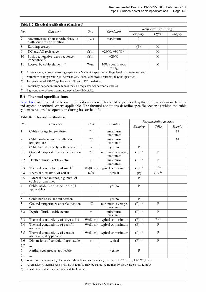
Recommended Practice DNV-RP-J301, February 2014
App.B Subsea power cable specifications – Page 143
B.4 Thermal specifications
Table B-3 lists thermal cable system specifications which should be provided by the purchaser or manufacturerand agreed or refined, where applicable. The thermal conditions describe specific scenarios which the cablesystem is required to operate in during its service life.
7 Asymmetrical short circuit, phase to earth, current and duration
kA, s maximum P
8 Earthing concept - - (P) M
9 DC and AC resistance Ω/m +20°C, +90°C 3) M
10 Positive, negative, zero sequence impedance 4)
Ω/m +20°C M
11 Losses, by cable element 5) W/m 100% continuous rating
M
1) Alternatively, a power carrying capacity in MVA at a specified voltage level is sometimes used.
2) Minimum or target value(s). Alternatively, conductor cross-section(s) may be specified.
3) Temperature of +90°C applies to XLPE and EPR insulation.
4) Frequency-dependent impedances may be requested for harmonic studies.
5) E.g. conductor, sheath, armour, insulation (dielectric).
Table B-3 Thermal specifications
No. Category Unit ConditionResponsibility at stage
Enquiry Offer Supply
1 Cable storage temperature °C minimum, maximum
M
2 Cable load-out and installation temperature
°C minimum, maximum
M
3 Cable buried directly in the seabed - yes/no P
3.1 Ground temperature at cable location ϑ
°C minimum, average, maximum
(P) 1) P
3.2 Depth of burial, cable centre m minimum, maximum
(P) 1) P
3.3 Thermal conductivity of soil k 2) W/(K·m) typical or minimum (P) 1) P 3)
3.4 Thermal diffusivity of soil α m2/s typical (P) (P) 3)
3.5 External heat sources, e.g. parallel cables or pipelines
- P
4 Cable inside J- or I-tube, in air (if applicable)
- yes/no P
4.1 ...
5 Cable buried in landfall section - yes/no P
5.1 Ground temperature at cable location ϑ
°C minimum, average, maximum
(P) 1) P
5.2 Depth of burial, cable centre m minimum, maximum
(P) 1) P
5.3 Thermal conductivity of (dry) soil k W/(K·m) typical or minimum (P) 1) P 3)
5.4 Thermal conductivity of backfill material k
W/(K·m) typical or minimum (P) 1) P
5.5 Thermal conductivity of conduit material k, if applicable
W/(K·m) typical or minimum (P) 1) P
5.6 Dimensions of conduit, if applicable m typical (P) 1) P
5.7 ...
6 Further scenario, as applicable - yes/no P
6.1 ...1) Where site data are not yet available, default values commonly used are: +15°C, 1 m, 1.43 W/(K·m).
2) Alternatively, thermal resistivity ρT in K·m/W may be stated. A frequently used value is 0.7 K·m/W.
3) Result from cable route survey or default value.
Table B-2 Electrical specifications (Continued)
No. Category Unit ConditionResponsibility at stage
Enquiry Offer Supply
DET NORSKE VERITAS AS
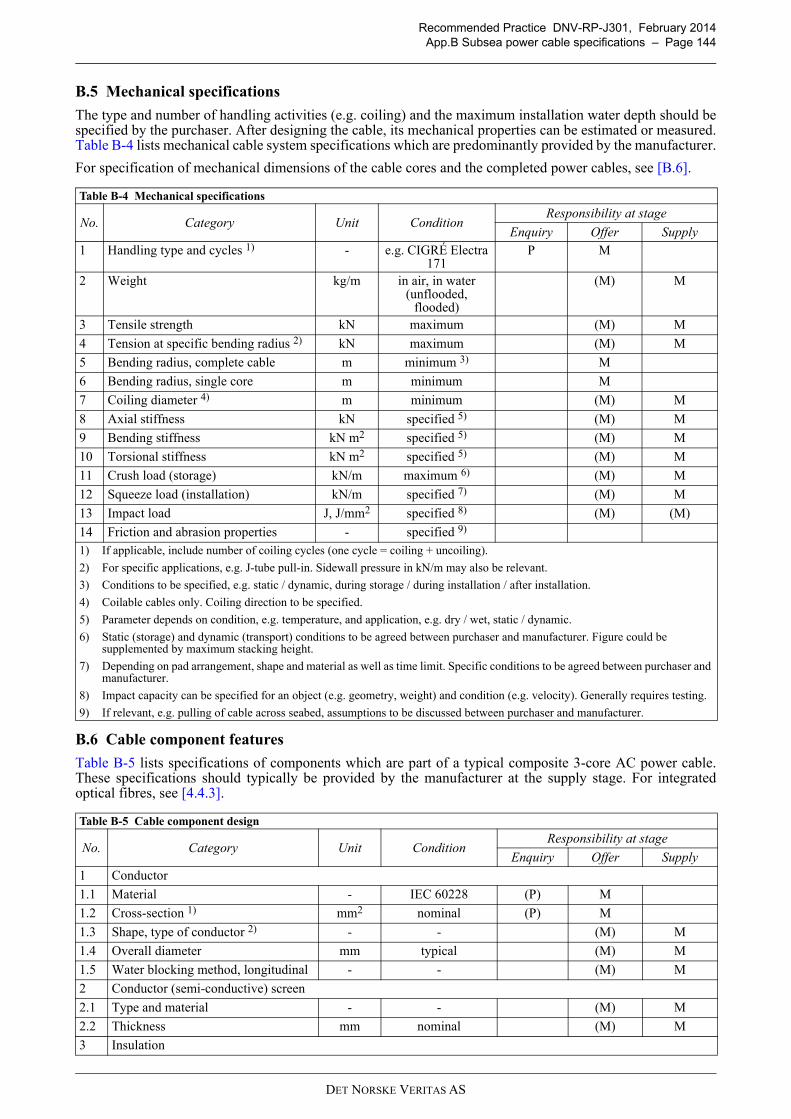
Recommended Practice DNV-RP-J301, February 2014
App.B Subsea power cable specifications – Page 144
B.5 Mechanical specifications
The type and number of handling activities (e.g. coiling) and the maximum installation water depth should bespecified by the purchaser. After designing the cable, its mechanical properties can be estimated or measured.Table B-4 lists mechanical cable system specifications which are predominantly provided by the manufacturer.
For specification of mechanical dimensions of the cable cores and the completed power cables, see [B.6].
B.6 Cable component features
Table B-5 lists specifications of components which are part of a typical composite 3-core AC power cable.These specifications should typically be provided by the manufacturer at the supply stage. For integratedoptical fibres, see [4.4.3].
Table B-4 Mechanical specifications
No. Category Unit ConditionResponsibility at stage
Enquiry Offer Supply
1 Handling type and cycles 1) - e.g. CIGRÉ Electra 171
P M
2 Weight kg/m in air, in water (unflooded,
flooded)
(M) M
3 Tensile strength kN maximum (M) M
4 Tension at specific bending radius 2) kN maximum (M) M
5 Bending radius, complete cable m minimum 3) M
6 Bending radius, single core m minimum M
7 Coiling diameter 4) m minimum (M) M
8 Axial stiffness kN specified 5) (M) M
9 Bending stiffness kN m2 specified 5) (M) M
10 Torsional stiffness kN m2 specified 5) (M) M
11 Crush load (storage) kN/m maximum 6) (M) M
12 Squeeze load (installation) kN/m specified 7) (M) M
13 Impact load J, J/mm2 specified 8) (M) (M)
14 Friction and abrasion properties - specified 9)
1) If applicable, include number of coiling cycles (one cycle = coiling + uncoiling).
2) For specific applications, e.g. J-tube pull-in. Sidewall pressure in kN/m may also be relevant.
3) Conditions to be specified, e.g. static / dynamic, during storage / during installation / after installation.
4) Coilable cables only. Coiling direction to be specified.
5) Parameter depends on condition, e.g. temperature, and application, e.g. dry / wet, static / dynamic.
6) Static (storage) and dynamic (transport) conditions to be agreed between purchaser and manufacturer. Figure could be supplemented by maximum stacking height.
7) Depending on pad arrangement, shape and material as well as time limit. Specific conditions to be agreed between purchaser and manufacturer.
8) Impact capacity can be specified for an object (e.g. geometry, weight) and condition (e.g. velocity). Generally requires testing.
9) If relevant, e.g. pulling of cable across seabed, assumptions to be discussed between purchaser and manufacturer.
Table B-5 Cable component design
No. Category Unit ConditionResponsibility at stage
Enquiry Offer Supply
1 Conductor
1.1 Material - IEC 60228 (P) M
1.2 Cross-section 1) mm2 nominal (P) M
1.3 Shape, type of conductor 2) - - (M) M
1.4 Overall diameter mm typical (M) M
1.5 Water blocking method, longitudinal - - (M) M
2 Conductor (semi-conductive) screen
2.1 Type and material - - (M) M
2.2 Thickness mm nominal (M) M
3 Insulation
DET NORSKE VERITAS AS
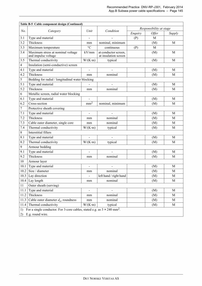
Recommended Practice DNV-RP-J301, February 2014
App.B Subsea power cable specifications – Page 145
3.1 Type and material - - (P) M
3.2 Thickness mm nominal, minimum (M) M
3.3 Maximum temperature °C continuous (P) M
3.4 Maximum stress at nominal voltage and impulse voltage
kV/mm at conductor screen, at insulation screen
(M) M
3.5 Thermal conductivity W/(K·m) typical (M) M
4 Insulation (semi-conductive) screen
4.1 Type and material - - (M) M
4.2 Thickness mm nominal (M) M
5 Bedding for radial / longitudinal water blocking
5.1 Type and material - - (M) M
5.2 Thickness mm nominal (M) M
6 Metallic screen, radial water blocking
6.1 Type and material - (M) M
6.2 Cross-section mm2 nominal, minimum (M) M
7 Protective sheath covering
7.1 Type and material - - (M) M
7.2 Thickness mm nominal (M) M
7.3 Cable outer diameter, single core mm nominal (M) M
7.4 Thermal conductivity W/(K·m) typical (M) M
8 Interstitial fillers
8.1 Type and material - - (M) M
8.2 Thermal conductivity W/(K·m) typical (M) M
9 Armour bedding
9.1 Type and material - - (M) M
9.2 Thickness mm nominal (M) M
10 Armour layer
10.1 Type and material - - (M) M
10.2 Size / diameter mm nominal (M) M
10.3 Lay direction - left hand / right hand (M) M
10.4 Lay length mm nominal (M) M
11 Outer sheath (serving)
11.1 Type and material - - (M) M
11.2 Thickness mm nominal (M) M
11.3 Cable outer diameter do, roundness mm nominal (M) M
11.4 Thermal conductivity W/(K·m) typical (M) M
1) For a single conductor. For 3-core cables, stated e.g. as 3 × 240 mm2.
2) E.g. round wire.
Table B-5 Cable component design (Continued)
No. Category Unit ConditionResponsibility at stage
Enquiry Offer Supply
DET NORSKE VERITAS AS