dnvgl-ru-ship-pt6ch8 living and working conditions · rules for classification: ships —...
TRANSCRIPT
The content of this service document is the subject of intellectual property rights reserved by DNV GL AS ("DNV GL"). The useraccepts that it is prohibited by anyone else but DNV GL and/or its licensees to offer and/or perform classification, certificationand/or verification services, including the issuance of certificates and/or declarations of conformity, wholly or partly, on thebasis of and/or pursuant to this document whether free of charge or chargeable, without DNV GL's prior written consent.DNV GL is not responsible for the consequences arising from any use of this document by others.
The electronic pdf version of this document, available free of chargefrom http://www.dnvgl.com, is the officially binding version.
DNV GL AS
RULES FOR CLASSIFICATION
ShipsEdition October 2015
Part 6 Additional class notations
Chapter 8 Living and working conditions

FOREWORD
DNV GL rules for classification contain procedural and technical requirements related to obtainingand retaining a class certificate. The rules represent all requirements adopted by the Society asbasis for classification.
© DNV GL AS October 2015
Any comments may be sent by e-mail to [email protected]
If any person suffers loss or damage which is proved to have been caused by any negligent act or omission of DNV GL, then DNV GL shallpay compensation to such person for his proved direct loss or damage. However, the compensation shall not exceed an amount equal to tentimes the fee charged for the service in question, provided that the maximum compensation shall never exceed USD 2 million.
In this provision "DNV GL" shall mean DNV GL AS, its direct and indirect owners as well as all its affiliates, subsidiaries, directors, officers,employees, agents and any other acting on behalf of DNV GL.

Part
6 C
hapt
er 8
Cha
nges
- c
urre
nt
Rules for classification: Ships — DNVGL-RU-SHIP-Pt6Ch8. Edition October 2015 Page 3Living and working conditions
DNV GL AS
CHANGES – CURRENT
This is a new document.
The rules enter into force 1 January 2016.
Part
6 C
hapt
er 8
Con
tent
s
Rules for classification: Ships — DNVGL-RU-SHIP-Pt6Ch8. Edition October 2015 Page 4Living and working conditions
DNV GL AS
CONTENTS
Changes – current...................................................................................................... 3
Section 1 Comfort class - COMF................................................................................. 61 General................................................................................................... 6
1.1 Introduction.........................................................................................61.2 Scope................................................................................................. 61.3 Application.......................................................................................... 61.4 Class notations.................................................................................... 61.5 Definitions and abbreviations.................................................................71.6 Documentation requirements................................................................. 81.7 Normative references..........................................................................11
2 Noise and vibration.............................................................................. 122.1 Requirements.....................................................................................122.2 Noise testing..................................................................................... 172.3 Vibration testing.................................................................................192.4 Test conditions...................................................................................20
3 Indoor climate...................................................................................... 213.1 General............................................................................................. 213.2 Requirements for on board climate.......................................................223.3 Certification and testing...................................................................... 253.4 System requirements..........................................................................26
Section 2 Vibration class - VIBR.............................................................................. 281 General................................................................................................. 28
1.1 Introduction.......................................................................................281.2 Scope............................................................................................... 281.3 Application.........................................................................................281.4 Definitions......................................................................................... 291.5 Documentation...................................................................................291.6 References.........................................................................................29
2 Vibration criteria...................................................................................302.1 General............................................................................................. 302.2 Structural vibration.............................................................................302.3 Vibration in machinery and components................................................ 31
3 Measurements.......................................................................................343.1 General............................................................................................. 34
Part
6 C
hapt
er 8
Con
tent
s
Rules for classification: Ships — DNVGL-RU-SHIP-Pt6Ch8. Edition October 2015 Page 5Living and working conditions
DNV GL AS
3.2 Test procedure................................................................................... 353.3 Test conditions...................................................................................363.4 Reporting.......................................................................................... 37
Section 3 Safe working conditions in container securing operations - SAFELASH.... 381 General................................................................................................. 38
1.1 Introduction.......................................................................................381.2 Scope............................................................................................... 381.3 Application.........................................................................................381.4 Definitions......................................................................................... 38
2 Documentation......................................................................................392.1 Documentation requirements............................................................... 39
3 Design requirements.............................................................................393.1 General............................................................................................. 393.2 Transit area....................................................................................... 393.3 Working area..................................................................................... 423.4 Fencing design................................................................................... 433.5 Access openings.................................................................................443.6 Ladders.............................................................................................443.7 Container securing equipment arrangement........................................... 453.8 Power supply..................................................................................... 453.9 Lighting.............................................................................................45
Part
6 C
hapt
er 8
Sec
tion
1
Rules for classification: Ships — DNVGL-RU-SHIP-Pt6Ch8. Edition October 2015 Page 6Living and working conditions
DNV GL AS
SECTION 1 COMFORT CLASS - COMF
1 General
1.1 IntroductionThe additional class notation COMF (V-crn, C-crn) is applicable for all ship types. The class notation COMF(V-crn, C-crn) indicates that comfort conditions that may adversely influence human performance onboard ships have been taken into consideration, and that the vessel satisfies acceptable levels of noise andvibration and indoor climate on board ships. The qualifierV-crn indicates to what level the requirementsrelated to noise and vibration have been achieved, and C-crn indicates to what the requirements related toindoor climate have been achieved.
1.2 ScopeThe additional class notation COMF includes requirements for noise levels, vibration levels and theperformance of the on board HVAC system, for passenger ships, cargo ships, yachts and high-speed crafts.The areas included are cabins, public spaces, wheelhouse, radio rooms, offices, control rooms, hospital andrecreation rooms.Compliance with the rules shall be verified through measurements of defined environmental parameters.Possible influence of vibration on machinery, structure or other systems is considered in other relevantSociety rules. The least strict noise level and sound insulatioCOMFn requirements (crn = 3) for cargo shipscorrespond to the requirements in IMO MSC 337(91) "Code on noise levels on board ships". In order toachieve the class notation , the vibration criteria's in this section shall also be satisfied.
1.3 ApplicationThe additional class notation COMF (V-crn, C-crn) is applicable to ships which comply with all therequirements to noise, vibrations and indoor climate. Criteria for providing a comfort rating number (crn)are divided into three groups 1, 2, and 3 depending on the level of comfort achieved. crn = 1 represents thehighest comfort level and crn = 3 represents an acceptable level of comfort.
1.4 Class notationsShips constructed in accordance with the requirements as specified in Table 1 will be assigned the classnotations as follows:

Part
6 C
hapt
er 8
Sec
tion
1
Rules for classification: Ships — DNVGL-RU-SHIP-Pt6Ch8. Edition October 2015 Page 7Living and working conditions
DNV GL AS
Table 1 Class notation and qualifiers
Class notation Qualifier Requirements
Name Description Name Description
V Noise and vibration [2]
C Indoor climate [3]
COMF
Requirements related tocomfort conditions thatmay adversely influencehuman performance. crn
For each of the qualifiersV and C a separatecomfort rating numbercrn will be set up. crnwill be set to 1, 2 or 3depending on the levelof comfort achieved.crn = 1 represents thehighest comfort leveland crn = 3 representsan acceptable level ofcomfort.
1.5 Definitions and abbreviations1.5.1 DefinitionsThe main parameters determining the comfort on board a ship are defined in Table 2 below. Furtherdefinitions of sound and vibration quantities and units are given in ISO 80000-8 and ISO 1683.
Table 2 Definitions
Air supply quantity The total amount of supplied air to any given space which may consist of a percentagere-circulated return air in addition to the fresh air supply quantity.
Air temperature control span The temperature interval which each designated space shall be able to satisfy.
Air velocity The measured mean absolute velocity of a mass of air in motion.
Ambient outside air temperature The actual air temperature measured out of direct sun exposure outside of the ship,expressed in °C.
Cabin An accommodation room intended for sleeping or recreation only.
Cargo ship Any ship, not specifically a passenger ship, yacht or high-speed craft, which is usedcommercially.
Draught The depth of a ship’s keel below the surface, [2].Air flow which may cause unwanted local cooling of the body, [3].
Fresh Air supply quantity The quantity of fresh/ outside air per person supplied to a space, expressed in litres/sor m3/h.
Indoor climate Indoor ambient temperature, temperature gradient, air velocity, humidity and carbondioxide concentration used as descriptors for indoor climate.
Noise Audible air pressure fluctuations generated by ship machinery, equipment or structure.

Part
6 C
hapt
er 8
Sec
tion
1
Rules for classification: Ships — DNVGL-RU-SHIP-Pt6Ch8. Edition October 2015 Page 8Living and working conditions
DNV GL AS
Noise level A-weighted sound pressure level LAeq(T), measured by a sound level meter in whichthe frequency response is weighted according to the A-weighting curve (ref. IEC61672-1).
Open deck recreation/
Outdoor passenger areas
Any area accessible to passengers during normal operation of the vessel.
Public spaces Communal indoor areas, e.g. restaurants, theatres, cinema, discos, shops, readingrooms, game rooms, gymnasiums, hobby rooms etc. Corridors, washrooms and toiletsare excluded.
Relative humidity Relative humidity is the actual amount of water vapour in the air compared to thesaturation amount of water vapour in the air at the same temperature and pressure.Usually expressed as percentage of saturated air having a relative humidity of 100%.
Relative humidity range The range of which relative humidity must be within during all outdoor conditions theHVAC system is designed for.
Temperature The average temperature of a specific number of temperature measurements in aparticular space, expressed in °C.
Thermal comfort A temperature range perceived as comfortable for most persons indoor.
Vertical gradient Vertical air temperature difference.
Vibration Structural motion in the frequency range 1 Hz to 80 Hz.
Vibration level The overall frequency weighted r.m.s. value of vibration velocity measured inaccordance with ISO 6954:2000.
1.5.2 Abbreviations
Table 3 Abbreviations
ASHRAE American Society of Heating, Refrigerating and Air-conditioning Engineers Inc.
CIBSE The Chartered Institution of Building Services Engineers
HVAC Heating, ventilation and air conditioning
IEC International Electrotechnical Commission
IMO International Maritime Organization
ISO International Organization for Standardization
WMO World Meteorological Organization
1.6 Documentation requirements1.6.1 Noise and vibration - qualifier VDocumentation shall be submitted as required by Table 4:

Part
6 C
hapt
er 8
Sec
tion
1
Rules for classification: Ships — DNVGL-RU-SHIP-Pt6Ch8. Edition October 2015 Page 9Living and working conditions
DNV GL AS
Table 4 Documentation requirements for qualifierV
Object Documentation type Additional description Info
Z250 – Procedure
A detailed plan for the measurements prior to the execution,containing:
— specification of measuring locations,
— expected loading condition during the measurements and normalrange of loading conditions for the vessel,
— required operating conditions for the vessel during themeasurements, i.e.: rotational speed, pitch and load of anypropeller / thruster at the test condition. Rotational speed and loadof any engine to be used during the test. Estimated vessel speedthrough water,
— instrumentation to be used, including date of last calibration,
— on request documentation describing the deck covering,joiner panels, ceiling panels and insulation to be used in theaccommodation.
AP
Noise andvibration
Z266 –Measurement report
Including:
— conditions during the measurements such as power output,propeller/engine speed, propeller pitch setting, draught, waterdepthunder keel, wind and sea state, vessel speed through water,
— the positions of the noise measurements shall be plotted on generalarrangement plans, [2.2.2],
— the dB(A) noise levels for each location shall be listed in tables andpreferably plotted on general arrangement plans,
— sound insulation and impact sound results if required,
— general arrangement plans showing the location of the vibrationmeasuring positions and their direction of measurements, [2.3.2],
— tables of vibration levels for each location,
— for locations with vibration levels exceeding the requirements, thefrequency spectra shall be included in the report,
— description of instrumentation which has been used, including dateof calibration and calibration procedure,
— description of any deviations from the required measurementprocedures,
— for informative purposes it is recommended that frequency spectrafor the different locations are enclosed.
AP
Info: AP – For approval, FI: For information
For general requirements to documentation, including definition of the Info codes, see Pt.1 Ch.3 Sec.2.For a full definition of the documentation types, see Pt.1 Ch.3 Sec.3.
1.6.2 Indoor climate - qualifierCDocumentation shall be submitted as required by Table 5:

Part
6 C
hapt
er 8
Sec
tion
1
Rules for classification: Ships — DNVGL-RU-SHIP-Pt6Ch8. Edition October 2015 Page 10Living and working conditions
DNV GL AS
Table 5 Documentation requirements for qualifierC
Object Documentation type Additional description Info
S120 – Heat balancecalculation
FI
Z100 – Specification HVAC plant
Air filter data.FI
S013 – Ducting andinstrumentation diagram(D&ID)
FI
On board environment
Z253 - Test procedure forquay and sea trial
Including:
— operating condition ofthe vessel during thetesting,
— required operatingcondition of the HVACplant,
— specification ofmeasurement locations,
— test responsible,
— test instrumentation.
AP
Z263 – Report from quayand sea trial
Including:
— identity and descriptionof the spaces,
— details of type and makeof instrumentation used,
— instrument calibrationdata,
— vessel and HVACoperating conditions,
— outdoor climaticconditions,
— measured climateparameters.
AP
On board environment
Z266 – Measurement report Measured air quantities inaccommodation spaces. FI
Info: AP – For approval, FI: For information
For general requirements to documentation, including definition of the Info codes, see Pt.1 Ch.3 Sec.2.For a full definition of the documentation types, see Pt.1 Ch.3 Sec.3.

Part
6 C
hapt
er 8
Sec
tion
1
Rules for classification: Ships — DNVGL-RU-SHIP-Pt6Ch8. Edition October 2015 Page 11Living and working conditions
DNV GL AS
1.7 Normative referencesInternational standards specifying criteria related to comfort aspects of noise, vibration and climate havebeen used as basis for the rules combined with current knowledge about achievable shipboard levels applyinggood engineering practice.The normative references are cited at appropriate places in the text. For dated references, only theedition cited applies. For undated references, the latest edition of the referenced document including anyamendments applies.The rules contain references to the following publications:
1.7.1 Noise
— IEC 61672-1 Electroacoustics - Sound level meters - Part 1: Specifications,— IMO MSC 337(91) Code on noise levels on board ships,— ISO 80000-8, Quantities and units,— ISO 1683. Preferred reference values for acoustical and vibratory levels,— ISO 717-1:2013, Acoustics – Rating of sound insulation in buildings and of building elements – Part 1:
Airborne sound insulation,— ISO 717-2:2013, Acoustics – Rating of sound insulation in buildings and of building elements – Part 2:
Impact sound insulation,— ISO 140-4:1998, Acoustics – Measurements of sound insulation in buildings and of building elements,— Part 4: Field measurements of airborne sound insulation between rooms,— ISO 140-7, Acoustics — Measurements of sound insulation in buildings and of building elements – Part 7:
Field measurements of impact sound insulation of floors,— ISO 10140-2:2010, Acoustics – Laboratory measurement of sound insulation of building elements – Part
2: Measurement of airborne sound insulation.
1.7.2 Vibration
— ISO 6954:2000 Mechanical vibration and shock – Guidelines for the overall evaluation of vibration inmerchant ships,
— ISO 2041:2009, Mechanical vibration, shock and condition monitoring - Vocabulary,— ISO 2631-1:1997/Amd 1:2010, Mechanical vibration and shock – Evaluation of human exposure to whole-
body vibration – Part 1: General requirements.
1.7.3 Climate
— ISO 7547, Shipbuilding – Air-conditioning and ventilation of accommodation spaces on board ships –Design conditions and basis of calculations,
— ISO 7730, Ergonomics of the thermal environment – Analytical determination and interpretation ofthermal comfort using calculation of the PMV and PPD indices and local thermal comfort criteria,
— ISO 7726, Ergonomics of the thermal environment – Instruments for measuring physical quantities,— ASHRAE, Applications Handbook. American Society of Heating, Refrigerating and Air-Conditioning
Engineers Inc. Atlanta, 91,— ANSI/ASHRAE, Standard 55-2004; Thermal Environmental Conditions for Human Occupancy,— ANSI/ASHRAE, Standard 62.1 – 2007, Ventilation for Acceptable Indoor Air Quality,— CIBSE Commissioning Code A: 1996 (2006); Air Distribution Systems (The Chartered Institute of Building
Service Engineers).

Part
6 C
hapt
er 8
Sec
tion
1
Rules for classification: Ships — DNVGL-RU-SHIP-Pt6Ch8. Edition October 2015 Page 12Living and working conditions
DNV GL AS
2 Noise and vibration
2.1 Requirements2.1.1 General
2.1.1.1 Compliance with the rules shall be verified through measurements.Guidance note:It may be advantageous to carry out calculations at an early project stage in order to ensure that necessary noise and vibrationcontrol measures are included.
---e-n-d---of---g-u-i-d-a-n-c-e---n-o-t-e---
2.1.1.2 The required test conditions are given in [2.4].
2.1.1.3 The requirements for noise and vibration are set up for four types of ships; passenger ships, cargoships, yachts and high-speed craft. The requirements for each type of ship are divided in groups for specifiedlocations.
2.1.1.4 All locations specified in the tables below shall comply with the criteria in order to be assigned thenotation COMF with qualifier V. Dispensations from certain requirements may in special circumstancesbe granted by the Society, if it is documented that compliance will not be possible despite relevant andreasonable technical reduction measures. If dispensation is granted it shall be ensured that no crew memberis exposed to an Lex(24) exceeding 80 dB(A) or if wearing hearing protectors, not exceeding 105 dB(A). Thiswill be considered by the Society in each particular case.
Guidance note:Guidelines for handling of excessive noise and vibration levels are published by the Society.
---e-n-d---of---g-u-i-d-a-n-c-e---n-o-t-e---
2.1.1.5 The highest comfort rating number achieved for noise or vibration will determine the overall rating fornoise and vibration, e.g. a ship meeting crn = 2 for vibration and crn = 1 for noise will be denoted crn = 2.
2.1.1.6 For ships to be operated at DP (Dynamic Positioning) mode or if manoeuvring thrusters are intendedfor continuous operation for longer periods, the stated noise and vibration requirements shall be satisfiedwith the manoeuvring thrusters in operation.For passenger ships the given comfort rating number applies to the passenger areas only. The crew areasshall as a minimum comply with crn = 3 for cargo ships.
2.1.2 Noise criteria
2.1.2.1 The maximum allowed noise levels for different ships, localities and comfort standards are given inTable 6 to Table 10.
2.1.2.2 In Table 10 Yacht, the noise levels specified for the transit condition apply to smaller yachts notintended for overnight cruising. For yachts intended for overnight cruising, the rules for passenger ships shallapply for the transit condition.

Part
6 C
hapt
er 8
Sec
tion
1
Rules for classification: Ships — DNVGL-RU-SHIP-Pt6Ch8. Edition October 2015 Page 13Living and working conditions
DNV GL AS
Table 6 Passenger ships - passenger areas maximum noise levels in dB(A)
Comfort rating number (crn)Locations
1 2 3
Passenger top grade cabins 44 47 50
Passenger cabins, standard 49 52 55
Public spaces 55 58 60
Open deck recreation 1) 65 68 70
1) 5 dB(A) relaxation in sports areas, passage ways and near ventilation inlets and outlets
Table 7 Cargo ships < 10 000 GT 1) - maximum noise levels in dB(A)
Comfort rating number (crn)Locations
1 2 3
Wheelhouse 60 60 65
Radio room 55 55 60
Crew cabins 50 55 60
Crew public spaces 55 60 65
Hospital 55 58 60
Offices 60 60 65
Machinery control rooms 65 70 75
Open deck recreation 70 73 75
1) For working areas, navigation spaces, service spaces, machinery rooms and spaces not specified, the requirements ofIMO MSC 337(91) Code on noise levels on board ships apply.
Table 8 Cargo ships ≥10 000 GT 1) - Maximum Noise levels in dB(A)
Comfortrating
number(crn)
Locations
1 2 3
Wheelhouse 606065
Radio room 555560
Crew cabins 505355
Crew public spaces 555860
Hospital 555555
Offices 555860
Machinery control rooms 657075

Part
6 C
hapt
er 8
Sec
tion
1
Rules for classification: Ships — DNVGL-RU-SHIP-Pt6Ch8. Edition October 2015 Page 14Living and working conditions
DNV GL AS
Comfortrating
number(crn)
Locations
1 2 3
Open deck recreation 707375
1) For working areas, navigation spaces, service spaces, machinery rooms and spaces not specified, the requirements ofIMO MSC 337(91) Code on noise levels on board ships apply.
Table 9 High-speed Craft - Maximum Noise levels in dB(A)
Comfort rating number (crn)
100 m and below Above 100 mLocations
1 2 3 1 2 3
Passenger localities 70 72 75 60 65 68
Outdoor passenger areas 75 75 75 73 75 75
Navigation bridge 62 65 65 60 62 65
Service areas /shops/kiosk 70 73 75 65 68 70
Table 10 Yacht - Owner and Guest Areas Maximum Noise levels in dB(A)
Comfort rating number (crn)
In harbour condition Transit conditionLocations
1 2 3 1 2 3
Sleeping rooms 35 40 45 - - -
Lounges / Saloons 40 45 50 53 58 62
Outdoor recreation areas 50 55 60 75 80 85
Navigation bridge - - - 60 60 65
2.1.3 Sound insulation
2.1.3.1 The acoustic insulation between accommodation spaces shall at least satisfy the requirements forsound insulation given in Table 11 and Table 12.
2.1.3.2 Field measurements shall be performed according to ISO 140-4:1998. When the area tested is < 10 m2, aminimum value of 10 m2 shall be used for calculation of the R’W index.
2.1.3.3 Laboratory tests of sound insulation properties of bulkhead and deck materials may be allowed inaccordance with ISO 10140-2:2010.
Guidance note:In general the requirements apply to field measured insulation indexes which shall be verified through field measurements. However,for some of the less strict requirements for constructions identical to previous constructions where ample field measurements existin our files, we may allow verification based on laboratory data.

Part
6 C
hapt
er 8
Sec
tion
1
Rules for classification: Ships — DNVGL-RU-SHIP-Pt6Ch8. Edition October 2015 Page 15Living and working conditions
DNV GL AS
---e-n-d---of---g-u-i-d-a-n-c-e---n-o-t-e---
Table 11 Sound Insulation Indexes R’W (ISO 717-1:2013) for crew areas
Comfort rating number (crn)Locations
1 2 3
Cabin to cabin (crew) 38 35 32
Cabin (crew) to corridor or cabin with communicating door 37 32 28
Cabin (crew) to mess rooms, recreation rooms, public spaces andentertainment areas
50 47 42
Note: Hospitals shall be subject to the same insulation requirements as crew cabins.
Table 12 Sound Insulation Indexes R’W (ISO 717-1:2013) for passenger areas
Comfort rating number (crn)Locations
1 2 3
Cabin to cabin (passenger standard) 41 38 35
Cabin to cabin (passenger top grade) 46 43 40
Cabin (passenger standard) to corridor or cabin with communicating door 38 35 33
Cabin (passenger top grade) to corridor or cabin with communicatingdoor
41 39 37
Passenger Cabin (standard) to mess rooms, recreation rooms, publicspaces
51 48 45
Passenger (top grade) Cabin to mess rooms, recreation rooms, publicspaces
56 53 50
Passenger cabin to entertainment area 65 62 60
2.1.3.4 The laboratory measured sound insulation (RW)for the bulkheads and decks shall be at least 3 dBhigher than the field measured (R’W) values.
Guidance note:Care should be exercised when mounting loudspeakers to the structure, so that noise transmission from the loudspeaker to thestructure is avoided.
---e-n-d---of---g-u-i-d-a-n-c-e---n-o-t-e---
2.1.4 Impact sound insulation, passenger ships
2.1.4.1 For passenger cabins the normalized impact sound pressure level (ISO 717-2:2013) shall not exceed50 dB. For passenger cabins below areas with wooden deck, marble deck or similar hard deck coveringmaterials, the above requirement may be relaxed to 57 dB.
2.1.4.2 For passenger cabins located below dance floors, stages and gymnasiums, a normalized impact soundpressure level shall not exceed 45 dB.
2.1.5 Vibration criteria
2.1.5.1 The criteria to be met are given in Table 13 to Table 16.

Part
6 C
hapt
er 8
Sec
tion
1
Rules for classification: Ships — DNVGL-RU-SHIP-Pt6Ch8. Edition October 2015 Page 16Living and working conditions
DNV GL AS
2.1.5.2 The vibration limits are given in vibration velocity as frequency weighted overall r.m.s. values from 1Hz to 80 Hz. The weighting curve to be applied is specified in ISO 6954:2000.
2.1.5.3 The specified vibration criteria apply to the maximum level, of vertical, longitudinal and transversalvibration which shall be assessed separately.
Table 13 Passenger ships, Passenger Areas, Frequency weighted r.m.s. maximum values in mm/sfrom 1 Hz to 80 Hz
Comfort rating number (crn)Locations
1 2 3
Passenger top grade cabins 1.5 1.5 2.0
Passenger cabins, standard 1.5 2.0 3.0
Public Spaces 1.5 2.0 3.0
Open deck recreation 2.0 2.7 3.5
For passenger ships with comfort rating 1, no single frequency component within the frequency range 6.3 Hzto 12.5 Hz shall exceed 1 mm/s r.m.s. (weighted) for the indoor areas.
Guidance note:[2.1.5.3] implies that if measured vibration levels are below 1.0 mm/s r.m.s., crn = 1 is met. For vibration levels exceeding 1.0 mm/s r.m.s., the frequency spectra have to be examined in the frequency range 6.3 Hz to 12.5 Hz.
---e-n-d---of---g-u-i-d-a-n-c-e---n-o-t-e---
Table 14 Cargo ships Frequency weighted r.m.s. maximum values in mm/s from 1 Hz to 80 Hz
Comfort rating number (crn)Locations
1 2 3
Cabins 2.0 2.7 3.5
Mess/recreation rooms 2.0 2.7 3.5
Offices 2.0 2.7 3.5
Navigation Bridge 2.0 2.7 3.5
Control rooms 2.7 2.7 3.5
Work spaces 3.5 3.5 4.0
2.1.5.4 For cargo ships with crn = 3, except for work spaces, no single frequency component within thefrequency range 1.0 Hz to 8.0 Hz shall exceed 2.7 mm/s r.m.s. (weighted).
Guidance note:[2.1.5.4] implies that if measured vibration levels are below 2.7 mm/s r.m.s., crn = 3is met. For vibration levels exceeding 2.7 mm/s r.m.s., the frequency spectra have to be examined in the frequency range 1.0 Hz to 8.0 Hz.
---e-n-d---of---g-u-i-d-a-n-c-e---n-o-t-e---
Part
6 C
hapt
er 8
Sec
tion
1
Rules for classification: Ships — DNVGL-RU-SHIP-Pt6Ch8. Edition October 2015 Page 17Living and working conditions
DNV GL AS
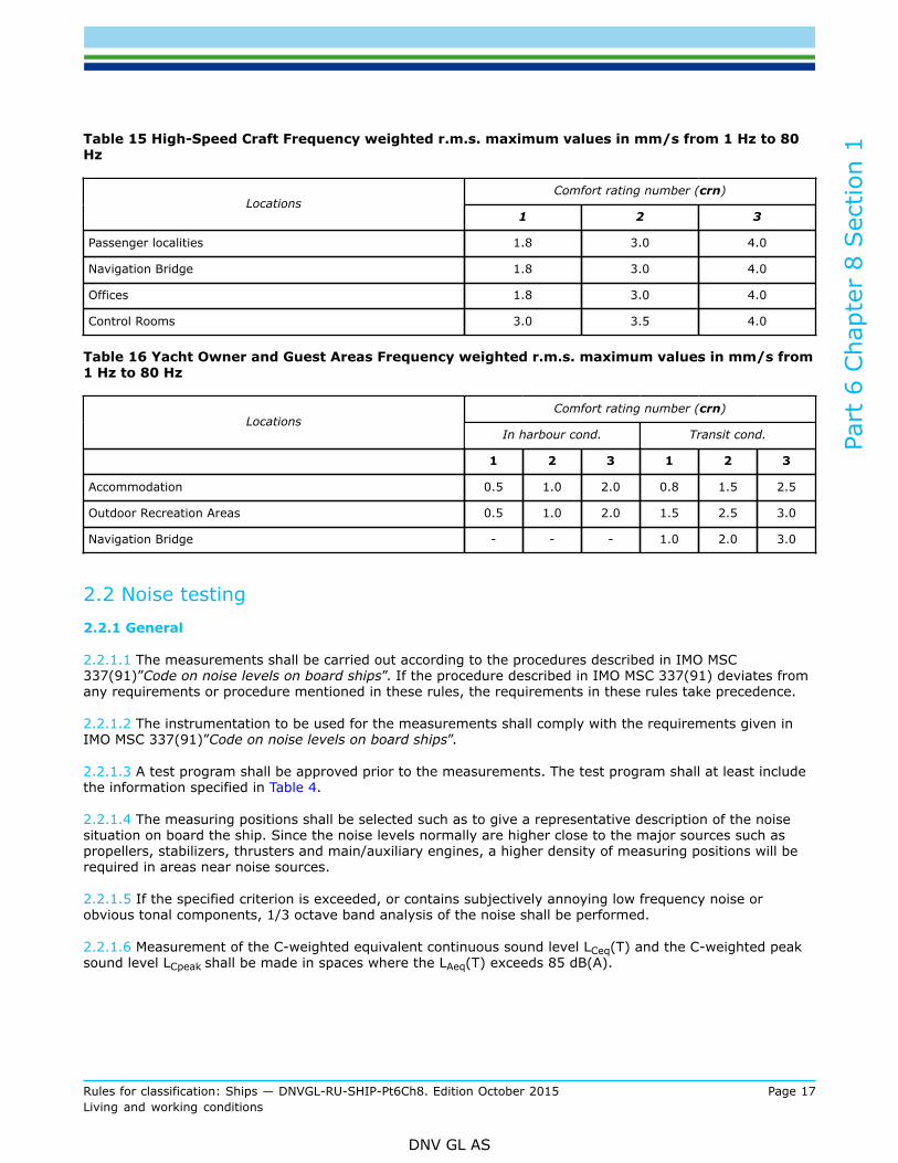
Table 15 High-Speed Craft Frequency weighted r.m.s. maximum values in mm/s from 1 Hz to 80Hz
Comfort rating number (crn)Locations
1 2 3
Passenger localities 1.8 3.0 4.0
Navigation Bridge 1.8 3.0 4.0
Offices 1.8 3.0 4.0
Control Rooms 3.0 3.5 4.0
Table 16 Yacht Owner and Guest Areas Frequency weighted r.m.s. maximum values in mm/s from1 Hz to 80 Hz
Comfort rating number (crn)Locations
In harbour cond. Transit cond.
1 2 3 1 2 3
Accommodation 0.5 1.0 2.0 0.8 1.5 2.5
Outdoor Recreation Areas 0.5 1.0 2.0 1.5 2.5 3.0
Navigation Bridge - - - 1.0 2.0 3.0
2.2 Noise testing2.2.1 General
2.2.1.1 The measurements shall be carried out according to the procedures described in IMO MSC337(91)”Code on noise levels on board ships”. If the procedure described in IMO MSC 337(91) deviates fromany requirements or procedure mentioned in these rules, the requirements in these rules take precedence.
2.2.1.2 The instrumentation to be used for the measurements shall comply with the requirements given inIMO MSC 337(91)”Code on noise levels on board ships”.
2.2.1.3 A test program shall be approved prior to the measurements. The test program shall at least includethe information specified in Table 4.
2.2.1.4 The measuring positions shall be selected such as to give a representative description of the noisesituation on board the ship. Since the noise levels normally are higher close to the major sources such aspropellers, stabilizers, thrusters and main/auxiliary engines, a higher density of measuring positions will berequired in areas near noise sources.
2.2.1.5 If the specified criterion is exceeded, or contains subjectively annoying low frequency noise orobvious tonal components, 1/3 octave band analysis of the noise shall be performed.
2.2.1.6 Measurement of the C-weighted equivalent continuous sound level LCeq(T) and the C-weighted peaksound level LCpeak shall be made in spaces where the LAeq(T) exceeds 85 dB(A).
Part
6 C
hapt
er 8
Sec
tion
1
Rules for classification: Ships — DNVGL-RU-SHIP-Pt6Ch8. Edition October 2015 Page 18Living and working conditions
DNV GL AS
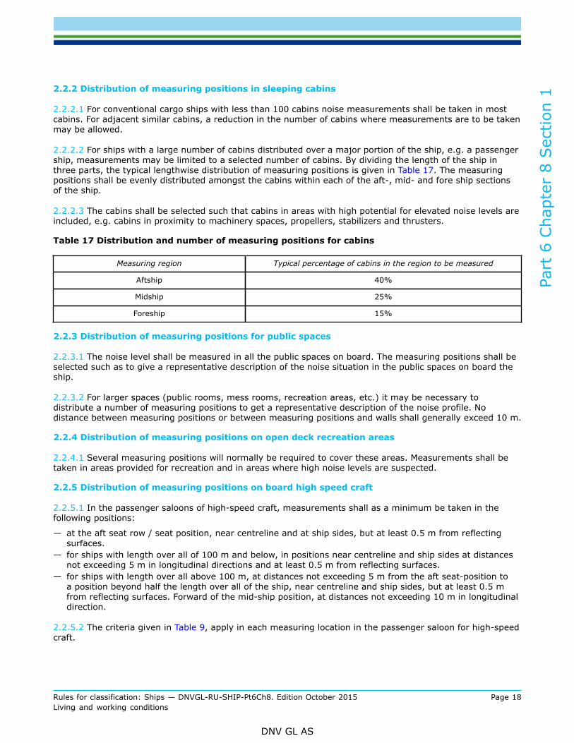
2.2.2 Distribution of measuring positions in sleeping cabins
2.2.2.1 For conventional cargo ships with less than 100 cabins noise measurements shall be taken in mostcabins. For adjacent similar cabins, a reduction in the number of cabins where measurements are to be takenmay be allowed.
2.2.2.2 For ships with a large number of cabins distributed over a major portion of the ship, e.g. a passengership, measurements may be limited to a selected number of cabins. By dividing the length of the ship inthree parts, the typical lengthwise distribution of measuring positions is given in Table 17. The measuringpositions shall be evenly distributed amongst the cabins within each of the aft-, mid- and fore ship sectionsof the ship.
2.2.2.3 The cabins shall be selected such that cabins in areas with high potential for elevated noise levels areincluded, e.g. cabins in proximity to machinery spaces, propellers, stabilizers and thrusters.
Table 17 Distribution and number of measuring positions for cabins
Measuring region Typical percentage of cabins in the region to be measured
Aftship 40%
Midship 25%
Foreship 15%
2.2.3 Distribution of measuring positions for public spaces
2.2.3.1 The noise level shall be measured in all the public spaces on board. The measuring positions shall beselected such as to give a representative description of the noise situation in the public spaces on board theship.
2.2.3.2 For larger spaces (public rooms, mess rooms, recreation areas, etc.) it may be necessary todistribute a number of measuring positions to get a representative description of the noise profile. Nodistance between measuring positions or between measuring positions and walls shall generally exceed 10 m.
2.2.4 Distribution of measuring positions on open deck recreation areas
2.2.4.1 Several measuring positions will normally be required to cover these areas. Measurements shall betaken in areas provided for recreation and in areas where high noise levels are suspected.
2.2.5 Distribution of measuring positions on board high speed craft
2.2.5.1 In the passenger saloons of high-speed craft, measurements shall as a minimum be taken in thefollowing positions:
— at the aft seat row / seat position, near centreline and at ship sides, but at least 0.5 m from reflectingsurfaces.
— for ships with length over all of 100 m and below, in positions near centreline and ship sides at distancesnot exceeding 5 m in longitudinal directions and at least 0.5 m from reflecting surfaces.
— for ships with length over all above 100 m, at distances not exceeding 5 m from the aft seat-position toa position beyond half the length over all of the ship, near centreline and ship sides, but at least 0.5 mfrom reflecting surfaces. Forward of the mid-ship position, at distances not exceeding 10 m in longitudinaldirection.
2.2.5.2 The criteria given in Table 9, apply in each measuring location in the passenger saloon for high-speedcraft.

Part
6 C
hapt
er 8
Sec
tion
1
Rules for classification: Ships — DNVGL-RU-SHIP-Pt6Ch8. Edition October 2015 Page 19Living and working conditions
DNV GL AS
2.2.6 Reporting
2.2.6.1 The report shall comply with the requirements in IMO MSC 337(91)”Code on noise levels on boardships” summarised in Table 4.
2.3 Vibration testing2.3.1 General
2.3.1.1 The measurements shall be carried out according to the procedures described in ISO 6954:2000.When the procedure described in ISO 6954:2000 deviates from any requirements or procedure mentioned inthese rules, the requirements in these rules take precedence.
2.3.1.2 A test program shall be approved prior to the measurements. The test program is at least to includethe information specified in Table 4.
2.3.1.3 The measuring positions shall be selected such as to give a representative description of the vibrationsituation on board the ship.
2.3.2 Measuring positions
2.3.2.1 Vibration measurements in cabins are normally to be taken at the floor in the centre of the room andshall reflect the vibration of the deck structure.
2.3.2.2 For larger spaces (public rooms, mess rooms, recreation areas, etc.) it may be necessary todistribute a number of measuring positions to get a representative description of the vibration profile.
2.3.2.3 On decks where the accommodation extends over a large proportion of the length of the ship, as forinstance passenger ships, it is recommended that the measuring positions should be distributed according tothe Table 18. The distribution shall be applied on each deck.
Table 18 Distribution of measuring positions
Measuring region Percentage of measuring positions to be placed in the region
Aftship 60%
Midship 30%
Foreship 10%
2.3.2.4 Vibration levels in vertical, longitudinal and transverse directions are subject to assessment.Recording of vibration levels in longitudinal and transverse direction is not required in all positions, but mustbe taken in sufficient number of positions in order to represent the global vibration of the deck according tothe paragraphs below.
Guidance note:For ships with the accommodation placed in a deck house, transversal vibration shall be recorded at the front and aft end, andlongitudinal vibration at the port and starboard side of the deck house at each deck level.
---e-n-d---of---g-u-i-d-a-n-c-e---n-o-t-e---
2.3.2.5 If the requirements to maximum vibration levels in the transversal and/or longitudinal directions aresatisfied on the highest deck levels, measurements on lower deck levels in the corresponding direction maybe omitted.
Part
6 C
hapt
er 8
Sec
tion
1
Rules for classification: Ships — DNVGL-RU-SHIP-Pt6Ch8. Edition October 2015 Page 20Living and working conditions
DNV GL AS
2.3.2.6 For ships where the accommodation extends over a large portion of the length of the ship, as forinstance for passenger ships, the transversal vibration shall be recorded at a minimum of three positions,evenly distributed along the ship. The longitudinal vibration shall be recorded at the bridge wings.
2.3.2.7 The distribution of the measuring positions shall be approved prior to the tests. Additional measuringpositions may be added by the surveyor during the survey on board the ship
2.3.3 Data acquisition
2.3.3.1 The vibration levels shall be measured as one weighted overall velocity level according to therequirements in ISO 6954:2000.
2.3.3.2 Frequency spectra shall be presented for at least two measuring locations on each deck and in allcases where the measured vibration level exceeds the specified maximum level. Frequency spectra shall bepresented for cargo ships with comfort rating crn = 3 for locations with vibration levels exceeding 2.7 mm/sand for passenger ships with comfort rating crn = 1 for locations with vibration levels exceeding 1.0 mm/s.
2.3.3.3 Frequency spectra for any other location shall be presented if requested by the Society.
2.3.3.4 For frequency spectra the following analysis parameters shall be applied:
— frequency range 1 to 80 Hz— frequency resolution shall be maximum 0.25 Hz— window function which gives an accurate estimate of the amplitudes in the frequency spectra (for instance
Flat top window)— the vibration recordings shall be averaged over a time period of approximately 1 min.
2.3.4 Reporting
2.3.4.1 The report shall at least contain the information specified in Table 4.
2.4 Test conditions2.4.1 General
2.4.1.1 The required ship operating conditions for these tests are based on IMO MSC 337(91) for noise andISO 6954:2000 for vibration. The operating conditions described in the referred documents shall be followed.When the test conditions described in the referred documents deviate from any requirements or procedurementioned in these rules, the requirements in these rules take precedence. The main operating conditionswith some additions are specified below.
2.4.1.2 Measurements shall be taken at normal operational condition of the vessel and no less than 80%of the maximum continuous power on the propeller shaft(s). All other machinery shall be run under normaloperating conditions during the tests. For some ship types the power to be used on the propeller shaft(s)shall be based on normal operation of the ship and will be determined and approved for each individual case.
2.4.1.3 The test should be conducted in a depth of water not less than three times the draught of the ship forships which normally are operated in deep waters. For ships to be operated continuously in shallow waters,the tests shall be performed at relevant depth of water. If the water depth is less than five times the draughtof the ship or if there are large reflecting surfaces in the vicinity of the test path this shall be described in thetest report.
2.4.1.4 The tests should be conducted in a slight sea (WMO Sea state 3 or less).

Part
6 C
hapt
er 8
Sec
tion
1
Rules for classification: Ships — DNVGL-RU-SHIP-Pt6Ch8. Edition October 2015 Page 21Living and working conditions
DNV GL AS
2.4.1.5 The measurements are to be taken with the ship loaded or ballasted to a loading condition(s) asclose as possible to the normal operating condition(s). For ships with larger variation than 25% in relevantdisplacements, measurements may be required at two loading conditions close to the relevant heavy andlight conditions. If it is difficult to achieve two loading conditions during the sea trial, one loading conditionmay be accepted. The loading condition(s) to be used shall be approved by the Society prior to the testing.
2.4.1.6 The rudder angle for a transit operating condition shall be minimised and preferably be restricted toabout 0 degrees ±2 degrees (minimum rudder action is desired).
2.4.1.7 For ships fitted with manoeuvring thruster(s) intended to be operated at DP or continuously for along period of time, measurements of noise and vibration shall be taken with the manoeuvring thruster(s)operating on at least 40% power and the ship’s speed shall be appropriate for thruster operation.
Guidance note:For ships fitted with manoeuvring thruster(s) not to be operated at DP or continuously for a long period of time, measurements inadjacent locations affected by noise from the thruster(s) shall be taken with the manoeuvring thruster(s) operating on at least 40%power and the ship’s speed shall be appropriate for thruster operation. The measured levels should be reported for reference onlyand do not need to comply with the noise limits.
---e-n-d---of---g-u-i-d-a-n-c-e---n-o-t-e---
2.4.1.8 For ships equipped with stabilizers, the free sailing measurements shall be taken with the stabilizersengaged and active.
2.4.1.9 For yachts the noise and vibration levels shall be measured for a “normal” harbour condition. In thiscondition the power supply shall be provided by the yacht's auxiliary engine(s), the HVAC system shall be runat rated capacity and the power consumption shall be at least 50% of the normal service supply.
2.4.1.10 Any divergence from the above mentioned conditions shall be clearly stated in the report.
2.4.2 Noise
2.4.2.1 Air-conditioning supply and ventilation supply shall be run at normal capacity during the tests.
2.4.2.2 The rooms shall be fully equipped with actual deck covering (carpets, vinyl, etc.), ceiling, curtains,furniture, etc.
2.4.2.3 Doors and windows shall be closed.
2.4.3 Vibration
2.4.3.1 The decks shall be fully equipped with regards to outfit weights.
3 Indoor climate
3.1 General3.1.1 Rule applications
3.1.1.1 The rules outline standards, conventions, guidelines and specifications for the purpose ofcategorization of a ship's on board climate in relation to the performance of the on board heat, ventilation,and air conditioning (HVAC) plant at the typical ambient climatic conditions to which the ship will besubjected to during its intended use. See [3.2] on restrictions.

Part
6 C
hapt
er 8
Sec
tion
1
Rules for classification: Ships — DNVGL-RU-SHIP-Pt6Ch8. Edition October 2015 Page 22Living and working conditions
DNV GL AS
3.1.1.2 The rules apply to passenger ships with a dead-weight and/or length exceeding 100 tons or 50m andto combined cargo/passenger ships and cargo ships exceeding 300 tons deadweight.
3.1.1.3 The rules apply to the occupancy zone in designated locations specified in Table 19.
3.1.1.4 When setting the limits to the climate parameters, and determining the measuring procedure, dueconsideration has been given to technical and practical limitations inherent in the design and construction ofdifferent types of ship and localities.
3.2 Requirements for on board climate3.2.1 General
3.2.1.1 With the specified climate comfort of a room, the majority of the passengers and crew can safely andcomfortably perform normal activity over a prolonged period of time.
3.2.1.2 Compliance with the rules shall be verified through measurements and documentation.
3.2.1.3 All locations specified in Table 20 shall comply with the criteria in order to be assigned the additionalclass notation COMF( with qualifier C.
3.2.1.4 It shall be stated for which outside temperature and humidity range the ship shall complywithqualifierC. The outside temperature and humidity range for which the ship meets the COMF(C-crn) willbe given together with the notation. The class notation is only valid for temperature and humidity rangeswithin this given range.
3.2.2 Climate requirements
3.2.2.1 The standard applies to the designated accommodation spaces on board, classified as shown in Table19.
Table 19 Classification of accommodation spaces
Type A Cabins
Type B Hospital and ward rooms
Type C Wheelhouse, control rooms, office areas and public spaces intended for low physical activity such asconference rooms, libraries, card rooms, seating areas, etc.
Type D Public spaces intended for high physical activity such as show lounges, dining areas, atriums, casinos,shopping areas, bars, dance lounges, discos, gymnasiums, etc.
3.2.2.2 The requirements to air properties and quality at different localities and comfort standard are shownin Table 20.
3.2.2.3 Each designated space should be able to change from the lower to the higher temperature given inTable 20 within two hours. However for special areas, this temperature control span time criteria may beevaluated separately.

Part
6 C
hapt
er 8
Sec
tion
1
Rules for classification: Ships — DNVGL-RU-SHIP-Pt6Ch8. Edition October 2015 Page 23Living and working conditions
DNV GL AS
Table 20 Air properties and quality at different localities and comfort standard
Comfortrating
number
Minimum air temperature
control span 1)Designatedspace type
crn 15°C and below(outside)
40°C and above(outside)
Maximumair
velocity
Minimum freshair supply
quantity perperson 2)
Vertical airtemperaturedifference 4)
Relativehumidity-RH 3)
Min./Max.limit (°C)
Min./Max.limit (°C)
m/s litres/s m3/hour
°C %
A 12
3
18 to 2419.5 to 24
21 to 24
22 to 2823.5 to 28
25 to 28
0.250.35
0.40
109
8
36.032.4
28.8
2.02.5
3.0
30 to 6020 to 60
< 65
B 12
3
18 to 2419.5 to 24
21 to 24
22 to 2823.5 to 28
25 to 28
0.150.25
0.35
1210
8
43.236.0
28.8
2.02.5
3.0
30 to 6020 to 60
< 65
C 12
3
20 to 2421 to 24
22 to 24
23 to 2824 to 28
25 to 28
0.200.25
0.35
109
8
36.032.4
28.8
2.03.0
3.5
30 to 6020 to 60
< 65
D 12
3
20 to 2421 to 24
22 to 24
23 to 2824 to 28
25 to 28
0.250.30
0.40
109
8
36.032.4
28.8
2.03.0
3.5
30 to 6020 to 60
< 65
1) For outside temperatures between 15°C and 40°C, the control span is to comply with the graphs shown in Figure 1and Figure 2.
2) Unless otherwise specified by owner and yard, the number of persons in each designated space will be countedaccording to ISO7547.
3) Any relative humidity is to be within the range for all outdoor conditions the HVAC system is designed for. It is notnecessary to meet the whole range during the specified design condition.
4) Vertical air temperature difference is normally tested for the low temperature condition only.

Part
6 C
hapt
er 8
Sec
tion
1
Rules for classification: Ships — DNVGL-RU-SHIP-Pt6Ch8. Edition October 2015 Page 24Living and working conditions
DNV GL AS
Figure 1 Temperature control span, designated space type A and B
Figure 2 Temperature control span, designated space type C and D
3.2.2.4 For crn = 1: Individual and automatic room temperature control (with thermostat) of designatedspaces type A, B C and D are required.

Part
6 C
hapt
er 8
Sec
tion
1
Rules for classification: Ships — DNVGL-RU-SHIP-Pt6Ch8. Edition October 2015 Page 25Living and working conditions
DNV GL AS
3.2.2.5 For crn = 2 and crn = 3: Individual room temperature control of designated spaces type A, B, C andD is required.
3.2.2.6 For passenger ships the given comfort rating number applies to the passenger areas only. Unlessspecified, the crew areas shall comply with minimum rating crn = 3.
3.3 Certification and testing3.3.1 General
3.3.1.1 An evaluation of the basic HVAC design, calculation procedures and measurements on board,constitutes the basis for the compliance with the designated comfort rating number(crn).
3.3.1.2 In general, it may be difficult to achieve the variation in outdoor environment climate for which theHVAC is designed. Documentation showing the relation between outside temperature and the actual effecton cooling /heating unit shall be provided. This documentation may be given as a diagram showing requiredtotal cooling/heating effect as function of outside temperature and humidity. The scope of the test maytherefore be reduced as long as it can be demonstrated that the capacity and general function of the HVACplant can sustain a controlled climate on board according to the selected crn.
3.3.1.3 Climate parameters subjected to verification through measurements are:
— vertical air temperature difference,— air temperature control span,— maximum air velocity.
3.3.1.4 Verification tests shall be performed on board according to a specified program. Approval of thisprogram shall be obtained from the Society prior to the execution of measurements. This program shall atleast include the information specified in Table 5.
3.3.1.5 The measuring position in a location shall be selected such as to give a representative description ofthe on board climate or according to what is specified in [3.2] and [3.3].
3.3.1.6 Air relative humidity is based on documentation and needs in general not to be verified throughmeasurements.
3.3.1.7 Measurements shall be carried out by the Society or a 3rd party approved by the Society undersupervision by a surveyor on board.
3.3.1.8 A summary of documentation to be submitted to the Society is given in Table 5, with reference toPt.1 Ch.3.
3.3.2 Measuring locations
3.3.2.1 For ships with less than 100 cabins and the accommodation restricted to a separate section in theaft-ship, midship or in the fore-ship a full set of measurements applicable to climate parameters in Table 20shall be taken in the following minimum number of cabins (n = number of cabins):
— For n < 10 Measurements in all cabins— For 10 ≤ n ≤ 40 Measurements in min.10 cabins— For n ≥ 41 Measurements in min.25% of all cabins.
The cabins to be measured shall be evenly distributed amongst the cabins on each deck or in each respectivefire zone. The positions should include start and end of duct line, if relevant.

Part
6 C
hapt
er 8
Sec
tion
1
Rules for classification: Ships — DNVGL-RU-SHIP-Pt6Ch8. Edition October 2015 Page 26Living and working conditions
DNV GL AS
3.3.2.3 For ships with more than 100 cabins distributed over a major portion of the ship, e.g. passengerships, a full set of measurements shall be taken in minimum 10% of the cabins in each fire zone containingcabins on each deck. The cabins to be measured shall be evenly distributed amongst the cabins on each deckor in each respective fire zone. The positions should include start and end of duct line.
3.3.2.4 The climate parameters shall be measured in a representative number of public spaces on board. Themeasuring positions shall be selected such as to give a representative description of the climate in the publicspaces on board the ship.
3.3.2.5 The measurement positions may be subjected to alterations during the testing based on the actualfindings during the survey on board the ship.
3.3.3 Testing
3.3.3.1 The individual values of the climate parameters as stated in [3.3.3.2] to [3.3.3.5] shall be verifiedby measurements during normal operation. HVAC plant shall be operated with constant output temperatureduring testing.
3.3.3.2 Air supply quantityThe air quantity supplied to a designated space shall be measured according to guidelines issued by theCIBSE Commissioning code, series A, air distribution systems, or any equivalent approved standard.Documentation of measurements shall be submitted to the Society for approval.
3.3.3.3 Air temperature control spanThe air temperature in a designated space shall be measured at the geometrical centre of the location. Forlarger spaces the temperature shall be measured in a representative number of positions in the occupancyzone.In order to obtain the temperature span in each location, the measurements shall be carried out for thefollowing two conditions with constant setting on central HVAC unit:
— minimum setting on local temperature regulation— maximum setting on local temperature regulation.
The measurements shall be carried out at steady state conditions. The higher temperature criteria of thetemperature control span should be measured within 2 hours after lower temperature measurement (see[3.2.2.3]).
3.3.3.4 Vertical air temperature differenceThe vertical temperature difference in all designated spaces shall be measured in the geometric centre ofthe occupancy zone at the following distances above the floor: 0.2 m, 1.0 m and 1.8 m. For larger spacesmeasurements shall be taken in representative positions. The positions shall reflect the temperature at ankle,abdomen and head level.
3.3.3.5 Air VelocityThe mean air velocity is to be measured at the geometric centre of the room. However the surveyor mayrequest alterations of the measurement position based on findings during the survey. Typical alteration maybe to carry out the measurement at the most commonly occupied position in the room in question.
3.3.3.6 Minor deviations from the specified values in Table 20 may be acceptable in special cases. TheSociety decides whether to accept a deviation or not.
3.3.4 Reporting
3.3.4.1 The report shall contain the information specified in Table 5.
Part
6 C
hapt
er 8
Sec
tion
1
Rules for classification: Ships — DNVGL-RU-SHIP-Pt6Ch8. Edition October 2015 Page 27Living and working conditions
DNV GL AS
3.4 System requirements3.4.1 General
3.4.1.1 In case of system failure, the HVAC system shall, depending on the comfort rating number to beachieved, have a redundancy in designated spaces given in [3.4.2].
3.4.1.2 In order to achieve the designated comfort rating number (crn), the maintainability of the systemshall fulfil certain minimum requirements (see [3.4.3]).
3.4.2 HVAC system failure mode control
3.4.2.1 In case of system failure, a controlled climate in spaces designated A and B shall be restored aftermaximum 12 hours for comfort rating crn = 1 and crn = 2. If different failures, not related to each other,occur simultaneously, the required restoring time shall be increased by 12 hours.
3.4.2.2 The minimum required amount of spare parts to be available shall be agreed between the owner andthe supplier. The list should be available to the Society.
3.4.2.3 There is no redundancy requirement for comfort rating crn = 1, except for paragraph [3.4.2.4]below.
3.4.2.4 A minimum level of ventilation in hospitals and machinery control rooms shall be provided duringa system failure by means of separate forced ventilation. Regulation of the fans shall be located in therespective rooms. This ventilation shall keep the temperature below 35ºC and above 15ºC.
3.4.3 HVAC system maintainability
3.4.3.1 In order to guarantee a sustainable crn = 1, crn = 2 and crn = 3 climate, a degree of systemmaintainability is required.
3.4.3.2 It shall be possible to inspect, clean or replace ducts, central air handling units, air filters, dustcollectors, heat exchangers, re-heaters and air terminals at regular work intervals.
3.4.3.3 Inspection hatches/doors shall be installed for inspection and cleaning of ducts.
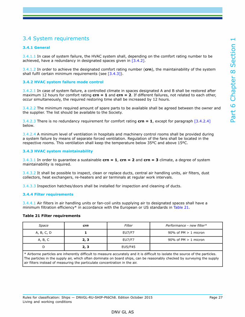
3.4.4 Filter requirements
3.4.4.1 Air filters in air handling units or fan-coil units supplying air to designated spaces shall have aminimum filtration efficiency* in accordance with the European or US standards in Table 21.
Table 21 Filter requirements
Space crn Filter Performance - new filter*
A, B, C, D 1 EU7/F7 90% of PM > 1 micron
A, B, C 2, 3 EU7/F7 90% of PM > 1 micron
D 2, 3 EU5/F45
* Airborne particles are inherently difficult to measure accurately and it is difficult to isolate the source of the particles.The particles in the supply air, which often dominate on board ships, can be reasonably checked by surveying the supplyair filters instead of measuring the particulate concentration in the air.

Part
6 C
hapt
er 8
Sec
tion
2
Rules for classification: Ships — DNVGL-RU-SHIP-Pt6Ch8. Edition October 2015 Page 28Living and working conditions
DNV GL AS
SECTION 2 VIBRATION CLASS - VIBR
1 General
1.1 IntroductionVibrations on a vessel may impair the proper functioning of essential machinery and equipment, and itmay cause fatigue damage to important structural elements of the vessel. The additional class notationVIBR indicates that vibrations to machinery, components and equipment, as well as to the structure incompartments where machinery, components and equipment are situated close to the propeller(s) have beenmeasured and evaluated, to avoid excessive shipboard vibrations.
1.2 ScopeThe scope of the additional class notation VIBR is to reduce the risk of failure in machinery, componentsand structures on board ships, caused by excessive vibration. This will be achieved through a proactive,systematic risk based plan for survey and measurement of main components on board. The requirements forthe additional class notation VIBR are additional to the requirements in the main class rules Pt.4 Ch.3 andPt.4 Ch.4. Compliance with the rules in this section shall be verified through survey and measurements inpredefined positions.
1.3 ApplicationThe additional class notation VIBR is applicable to machinery, components and equipment. It is alsoapplicable to the structure in compartments where machinery, components and equipment are situated closeto the propeller(s).The rules apply to the machinery components and structure as specified and described in [2]. An evaluationof the particular vessel is carried out prior to the measurements in order to reveal critical positions andcomplete the list for the particular vessel. The list with positions to be measured, including the correspondingvibration limits, is hereafter called the protocol. Vessels that fulfil the requirements for vibration classnotation may be assigned the additional class notation VIBR. The notation is applicable for both newbuildings and ships in operation. The following procedure shall be followed in order to attain the VIBRnotation:
— generation of the protocol,— carry out measurements on board according to the pre-defined protocol.When all measured positions are within the specified limits, the VIBR notation can be assigned.For similar vessels the same protocol may be used. However, separate measurements shall be carried out foreach vessel.If major modifications to the vessel, which may influence the vibration conditions on board, are carried out,new measurements may have to be taken in order to maintain the notation. This will be decided by theSocietyExcessive vibration levels will normally not be accepted. However, a risk based assessment of the actualposition and level will be carried out and a possible dispensation evaluated. This may require that moreextensive and frequent measurements have to be carried out or some sort of monitoring has to be installed.The vibration class notation shall not apply as the basis for class survey of items in the machinery inventorylist as described in Pt.7 Ch.1 Sec.4 [5].Machinery CM ([3] - Machinery and systems is the survey arrangement for machinery items in the inventorylist class based on condition monitoring.The influence of vibration from a comfort point of view is not included in this notation. The additional classnotation COMF (V, crn), see Sec.1, describes comfort limitations for noise, vibration and indoor climate, onboard ships.

Part
6 C
hapt
er 8
Sec
tion
2
Rules for classification: Ships — DNVGL-RU-SHIP-Pt6Ch8. Edition October 2015 Page 29Living and working conditions
DNV GL AS
1.4 Definitions1.4.1 General
1.4.1.1 Basic vibration quantities and units are defined in ISO 2041.
1.4.1.2 Vibration level: The specified vibration level is to be measured as r.m.s. velocity (mm/s), unlessr.m.s. displacement (mm) or r.m.s. acceleration (mm/s2) is specified.
1.4.1.3 Resonance: Coincidence between excitation frequency and natural frequency of the actual componentor structural position.
1.4.1.4 Structural vibration: Vibration level measured on the vessel structure.
1.4.1.5 Machinery vibration: Vibration level measured on machinery, components, equipment, pipes, etc.
1.4.1.6 Protocol: A document containing positions, requirements, test conditions and measured results. Theprotocol is specifically generated for each vessel.
1.4.1.7 Risk, the combination of the frequency of occurrence and the severity of the consequence.
1.4.1.8 Hazard, a potential to threaten human life, health, property or environment.
1.5 Documentation
1.5.1 Documentation shall be submitted as required by Table 1.
Table 1 Documentation requirements
Object Documentation type Additional description Info
Vibration G150 – Vibration measurement protocol AP
Info: AP – For approval, FI: For information
1.5.2 For general requirements to documentation, including definition of the info codes, see Pt.1 Ch.3 Sec.2.
1.5.3 For a full definition of the documentation types, see Pt.1 Ch.3 Sec.3.
1.6 References
1.6.1 International standards have been used as the foundation for these rules, but have not necessarilybeen explicitly followed. When setting the vibration limits and determining the measuring positions, dueconsideration has been given to technical and practical limitations inherent in the design and construction ofdifferent types of ship and localities. Unless a particular edition is referred to explicitly, the latest edition ofeach standard shall apply.
1.6.2 Where requirements described in the ISO standards deviate from these rules, the requirements in therules shall take precedence.
1.6.3 Vibration standards:

Part
6 C
hapt
er 8
Sec
tion
2
Rules for classification: Ships — DNVGL-RU-SHIP-Pt6Ch8. Edition October 2015 Page 30Living and working conditions
DNV GL AS
— ISO 2041, “Vibration and shock — Vocabulary”— ISO 4867, “Code for the measurement and reporting of shipboard vibration data”— ISO 4868, “Code for the measurement and reporting of local vibration data of ship structures and
equipment”.— ISO 10816-1, “Mechanical vibration-Evaluation of machine vibration by measurements on non-rotating
parts, Part 1: General guidelines”.
2 Vibration criteria
2.1 General2.1.1 Requirements
2.1.1.1 Compliance with the rules shall be verified through measurements. It may, however, beadvantageous to carry out a vibration assessment at an early project stage.
2.1.1.2 In order to be assigned the class notation VIBR, the requirements in [1.2.1.7] shall be met.However, in special cases small deviations from the requirements may be accepted depending upon positionand measured level. This will be decided by the Society in each particular case.
2.1.1.3 The vibration limits specified for structure aim at avoiding vibration induced fatigue cracks. Forstructure, used as foundation for equipment, the same limit as for the equipment shall be used. This is alsoapplicable for mast mounted equipment, i.e. the limit specified for a radar to be mounted on a mast will beapplied as the limit for the mast.
2.1.1.4 The vibration limits are in general given as r.m.s. vibration velocity. For some components restrictionto maximum allowable r.m.s. displacement in the low frequency range and r.m.s. acceleration in the highfrequency range are also specified.
2.2 Structural vibration2.2.1 Scope
2.2.1.1 Structural vibration should be limited in order to ensure structural integrity.
2.2.1.2 Structural vibration is a indicator of the risk of fatigue cracks in the structure. The level of vibrationcausing cracks will depend upon stress concentration factors, environment (corrosive medium) andworkmanship of local details.
2.2.1.3 The class notation is applicable to structure in compartments where machinery, components andequipment is situated as well as structure close to the propeller(s). The structure in cargo areas is notincluded.
2.2.2 Criteria
2.2.2.1 For structural vibration, the criteria specified in Table 2 and Table 3 are not to be exceeded. Vibrationlevels below the criteria gives low risk for fatigue cracks.
Table 2 Steel
Velocity
4 – 200 Hz
Part
6 C
hapt
er 8
Sec
tion
2
Rules for classification: Ships — DNVGL-RU-SHIP-Pt6Ch8. Edition October 2015 Page 31Living and working conditions
DNV GL AS
45 mm/s
Table 3 Aluminium
Velocity
4 – 200 Hz
15 mm/s
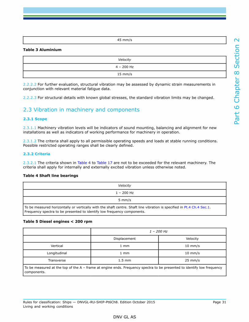
2.2.2.2 For further evaluation, structural vibration may be assessed by dynamic strain measurements inconjunction with relevant material fatigue data.
2.2.2.3 For structural details with known global stresses, the standard vibration limits may be changed.
2.3 Vibration in machinery and components2.3.1 Scope
2.3.1.1 Machinery vibration levels will be indicators of sound mounting, balancing and alignment for newinstallations as well as indicators of working performance for machinery in operation.
2.3.1.2 The criteria shall apply to all permissible operating speeds and loads at stable running conditions.Possible restricted operating ranges shall be clearly defined.
2.3.2 Criteria
2.3.2.1 The criteria shown in Table 4 to Table 17 are not to be exceeded for the relevant machinery. Thecriteria shall apply for internally and externally excited vibration unless otherwise noted.
Table 4 Shaft line bearings
Velocity
1 – 200 Hz
5 mm/s
To be measured horizontally or vertically with the shaft centre. Shaft line vibration is specified in Pt.4 Ch.4 Sec.1.Frequency spectra to be presented to identify low frequency components.
Table 5 Diesel engines < 200 rpm
1 – 200 Hz
Displacement Velocity
Vertical 1 mm 10 mm/s
Longitudinal 1 mm 10 mm/s
Transverse 1.5 mm 25 mm/s
To be measured at the top of the A – frame at engine ends. Frequency spectra to be presented to identify low frequencycomponents.
Part
6 C
hapt
er 8
Sec
tion
2
Rules for classification: Ships — DNVGL-RU-SHIP-Pt6Ch8. Edition October 2015 Page 32Living and working conditions
DNV GL AS
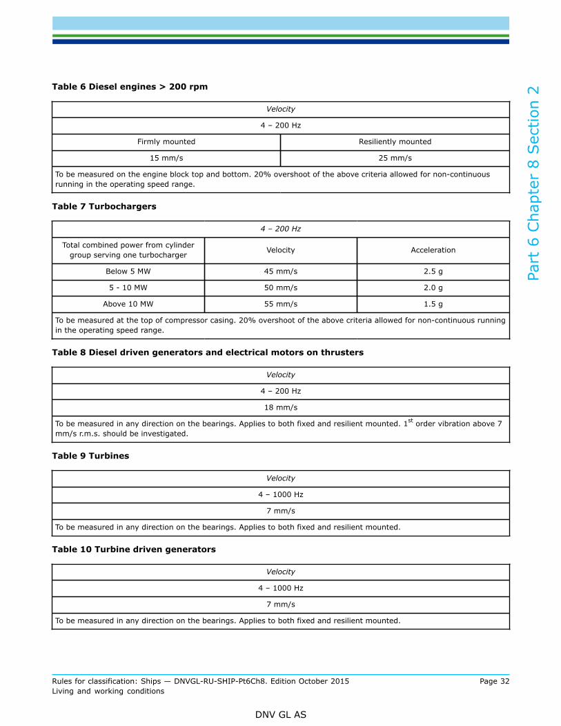
Table 6 Diesel engines > 200 rpm
Velocity
4 – 200 Hz
Firmly mounted Resiliently mounted
15 mm/s 25 mm/s
To be measured on the engine block top and bottom. 20% overshoot of the above criteria allowed for non-continuousrunning in the operating speed range.
Table 7 Turbochargers
4 – 200 Hz
Total combined power from cylindergroup serving one turbocharger Velocity Acceleration
Below 5 MW 45 mm/s 2.5 g
5 - 10 MW 50 mm/s 2.0 g
Above 10 MW 55 mm/s 1.5 g
To be measured at the top of compressor casing. 20% overshoot of the above criteria allowed for non-continuous runningin the operating speed range.
Table 8 Diesel driven generators and electrical motors on thrusters
Velocity
4 – 200 Hz
18 mm/s
To be measured in any direction on the bearings. Applies to both fixed and resilient mounted. 1st order vibration above 7mm/s r.m.s. should be investigated.
Table 9 Turbines
Velocity
4 – 1000 Hz
7 mm/s
To be measured in any direction on the bearings. Applies to both fixed and resilient mounted.
Table 10 Turbine driven generators
Velocity
4 – 1000 Hz
7 mm/s
To be measured in any direction on the bearings. Applies to both fixed and resilient mounted.

Part
6 C
hapt
er 8
Sec
tion
2
Rules for classification: Ships — DNVGL-RU-SHIP-Pt6Ch8. Edition October 2015 Page 33Living and working conditions
DNV GL AS
Table 11 Gears
Velocity
4 – 1000 Hz
7 mm/s
To be measured in any direction on the foundation and on the input shaft bearing
Table 12 Electric motors, separators, motor driven hydraulic pumps, fans not installed onreciprocating engines
Velocity
4.0 – 200 Hz 1)
Internal excited 7 mm/s 2)
External excited 12 mm/s 2)
To be measured in any direction on the bearings.
1) The upper frequency limit shall be at least 200 Hz and above 2 x rpm2) For vertically mounted motors the vibration level may be increased by 50% for the top of the motor.
Table 13 Compressors (screw or centrifugal)
Velocity
4 – 200 Hz 1)
Elastically mounted 10 mm/s
Fixed mounted 7 mm/s
To be measured in any direction on the bearings.
1) The upper frequency limit shall be at least 200 Hz and above 2x rpm
Table 14 Reciprocating compressors and reciprocating pumps
Velocity
4 – 200 Hz
30 mm/s
To be measured in any direction on the bearings. Applies for both resilient and fixed mounted.
Table 15 Boilers
Velocity
4 – 200 Hz
45 mm/s
To be measured on stiff parts, e.g. lugs, flanges etc.

Part
6 C
hapt
er 8
Sec
tion
2
Rules for classification: Ships — DNVGL-RU-SHIP-Pt6Ch8. Edition October 2015 Page 34Living and working conditions
DNV GL AS
Table 16 Pipes
Velocity
4 – 200 Hz
45 mm/s
Table 17 Electronic instruments and equipment
Velocity
4 – 200 Hz
Mounted on bulkheads 12 mm/s
Mounted on masts 20 mm/s
Mounted on machinery 25 mm/s
3 Measurements
3.1 General3.1.1 Scope
3.1.1.1 Vibration of structure and components shall be measured in order to ensure that the actual vibrationlevels onboard do not exceed the limits as defined in [2], before the VIBR notation can be assigned.
3.1.2 Requirements
3.1.2.1 The criteria for all relevant machinery are defined in [2]. With regard to the actual measurementpositions at each component, reference is made to ISO 10816-1.
3.1.2.2 The items to be fulfilled shall be listed in the protocol.Guidance note:An example of the protocol is shown in Table 18.
---e-n-d---of---g-u-i-d-a-n-c-e---n-o-t-e---
3.1.2.3 Information about running machinery and the actual operational conditions, i.e. power, rpm, etc. hasto be noted in the protocol before the measurements can start.
3.1.2.4 The measurements shall be carried out at a pre-defined steady state operating conditionrepresentative for future in-service operation (see also [3.2.1.2] and [3.3.1.4]).
3.1.2.5 r.m.s. value corresponding to the defined frequency range shall be measured.
3.1.2.6 The measured vibration levels shall be analysed applying FFT technique. For positions where themeasured level exceeds the level tabulated in the protocol, frequency spectra shall be included.
Guidance note:Machinery may exhibit stochastic vibration which will not be correctly represented in an FFT analyses. This will be most pronouncedfor elastically mounted machinery/equipment and mainly for the low frequency content of the vibration. The criteria are thereforemainly related to frequencies above 4 Hz where stochastic vibration is of minor importance.

Part
6 C
hapt
er 8
Sec
tion
2
Rules for classification: Ships — DNVGL-RU-SHIP-Pt6Ch8. Edition October 2015 Page 35Living and working conditions
DNV GL AS
---e-n-d---of---g-u-i-d-a-n-c-e---n-o-t-e---
3.1.2.7 For positions not predefined in the protocol, which are found during the survey to have high vibrationlevels, shall be included in the measurements.
Guidance note:Typical examples are pipes vital for the operation of the vessel. It is difficult to predefine all position to be measured, because theclamping carried out during installation will determine the effective length of the different sections and consequently the naturalfrequency. In these cases, it is up to the surveyor to inspect the pipes and sense if any magnification of the vibration is presentdue to resonance.
---e-n-d---of---g-u-i-d-a-n-c-e---n-o-t-e---
3.2 Test procedure3.2.1 Measurements
3.2.1.1 The protocol shall be approved by the Society prior to measurements being taken.Guidance note:The selection of components and positions to be measured includes a risk evaluation of the different components. The basis for therequirements is the vibration limits as defined in [2]. The result of this work is the protocol, as shown as an example in Table 18,to be filled in during the measurements onboard.
---e-n-d---of---g-u-i-d-a-n-c-e---n-o-t-e---
3.2.1.2 The measurements shall be carried out by a qualified vibration expert under supervision of asurveyor.
3.2.1.3 The measurements shall be analysed using FFT techniques, and presented in the frequency domain(frequency spectra).
3.2.1.4 Analysis parameters:
— frequency range 1−200 Hz (unless noted for special components)— at least 400 spectral-lines— window function which gives an accurate estimate of the amplitude value of the single components in the
frequency spectra (for instance flat top window)— the vibration recordings shall be averaged over a time period necessary to achieve a stable reading,
minimum 30 s.
3.2.1.5 The velocity levels shall be presented as r.m.s. values. For measured levels close to or exceeding thelimits, plot showing the vibration spectra for the actual positions shall be included.
3.2.1.6 Calibration of instruments shall be carried out minimum every second year or according to standards.
3.2.2 Protocol
3.2.2.1 Table 18 shows an example of the Vibration Measurement Protocol.
Table 18 Vibration Measurement Protocol for: (insert name of vessel)
System Position CheckedLimit
[mm/s]
Measured
[mm/s]
Max. Ampl./Freq.*
mm/s / [Hz]Comment

Part
6 C
hapt
er 8
Sec
tion
2
Rules for classification: Ships — DNVGL-RU-SHIP-Pt6Ch8. Edition October 2015 Page 36Living and working conditions
DNV GL AS
System Position CheckedLimit
[mm/s]
Measured
[mm/s]
Max. Ampl./Freq.*
mm/s / [Hz]Comment
* Only to be given when the vibration criterion is exceeded.System is the main machinery groupPosition is the actual measuring positionChecked some position may only be checked without further measurementsLimit is the predefined limit for the actual positionMeasured is the r.m.s. vibration level measured at the actual positionMax. Ampl./Freq. is the maximum vibration component and the corresponding frequencyFrequency is the frequency corresponding to a specific vibration component
3.2.2.2 Other components may be added to the protocol by the vibration expert or the Society as foundappropriate. This will normally be based on the walk-through survey.
3.3 Test conditions3.3.1 General
3.3.1.1 Generally the power output on the propeller shaft(s) shall correspond to contractual normal seagoingcondition, or at least 85% of maximum continuous power available on the propeller shaft(s), unless stateddifferently in the protocol. All other machinery shall be run under normal operating conditions during thetests. However, if other operational conditions are termed as critical, these conditions will be included in theprotocol and the measurements.
3.3.1.2 For engines and components operated at different RPM, a run-up may be required.
3.3.1.3 For ships normally operated in deep waters, the test should be conducted in a depth of water not lessthan four times the draught of the ship. For ships to be operated continuously in shallow waters, the testsshall be performed at the relevant depth of water.
3.3.1.4 The tests should be conducted in a sea state that does not significantly influence the measurementresults.
3.3.1.5 The loading condition(s) of the ship shall be as close as possible to normal operating condition(s). Forships with larger variation than 25% in relevant displacements, the measurements shall normally be takenat two loading conditions close to the relevant heavy and light condition. Where this is not possible from apractical point of view, a light and heavy ballast condition are to be applied. The loading condition(s) usedshall be approved by the Society, prior to testing.
3.3.1.6 The ship should sail on a straight course with minimum rudder deflection.
3.3.1.7 Any divergence from the above mentioned conditions shall be clearly stated in the report.
3.3.1.8 Special equipment and components, which are operated for limited periods, shall be included.
Part
6 C
hapt
er 8
Sec
tion
2
Rules for classification: Ships — DNVGL-RU-SHIP-Pt6Ch8. Edition October 2015 Page 37Living and working conditions
DNV GL AS
3.3.1.9 Information about running machinery and the actual ship operating conditions shall be noted in theprotocol.
3.4 Reporting3.4.1 General
3.4.1.1 Prior to the measurements a plan with the following information shall be issued:
— specification of measuring positions and corresponding limits, the protocol— required loading conditions— required operating conditions for machinery— instrumentation to be used.
3.4.1.2 After the measurements have been carried out, a report shall be issued. The report shall contain thefollowing information:
— ship and machinery particulars— condition during the measurements such as power output, propeller and or engine speed, draught, water
depth, wind and sea state— sketches or pictures showing the location of the measuring positions and their direction of measurements— tables of the measured vibration levels as defined in the protocol. The required frequency spectra for the
different positions shall be included— instrumentation that has been used, including type of analyzer, window function that has been applied,
averaging time and resolution— description of possible excessive vibration levels.

Part
6 C
hapt
er 8
Sec
tion
3
Rules for classification: Ships — DNVGL-RU-SHIP-Pt6Ch8. Edition October 2015 Page 38Living and working conditions
DNV GL AS
SECTION 3 SAFE WORKING CONDITIONS IN CONTAINER SECURINGOPERATIONS - SAFELASH
1 General
1.1 IntroductionThe additional class notation SAFELASH applies to vessels involved with transportation of containers. Theobjective of the additional class notation SAFELASH is to provide people safe working conditions in particularsafe access and safe places of work, when they are engaged in container securing operations on deck.
1.2 ScopeThe scope of the additional class notation SAFELASH is to ensure safer working conditions in containersecuring operations. This section describes requirements covering aspects within design and arrangement ofworking areas, container top working, fencing and fall protection, marking of obstacles and openings, designof walkways, ladders, steps and other means of access, design and arrangement of power supplies for reefercontainers and illumination of working areas and transit areas.
1.3 ApplicationShips complying with the requirements given in this section will be assigned the additional class notationSAFELASH. The additional class notation SAFELASH is applicable to ships designed for carrying containerson deck with either notation Container ship or Container. The additional class notation SAFELASH may beapplied to other ships upon request.The additional class notation SAFELASH intends to ensure the compliance with Code of Safe Practice forCargo Stowage and Securing (CSS Code) Annex 14 adopted by MSC.1/Circ.1352 and related IACS UISC265, considering design aspects to be implemented at the new building stage. The application of this classnotation visualizes compliance with CSS Code Annex 14 to all relevant parties including flag administrationsand port state authorities.
1.4 Definitions
1.4.1 Definitions used specially in this section are given in Table 1.
Table 1 Definitions
Lashing positions / working area Any positions or spaces used for operating container securing devices, e.g. in betweencontainer stows on hatch covers; lashing bridges and platforms.
Transit area Passage ways, stairs, decks and other areas used for moving about the ship.
Fencing A generic term for guardrails, safety rails, safety barriers and similar structures thatprovide protection against the falls of people.
Ladder stringers The uprights or sides of a ladder.
Rungs The bars that form the steps of a ladder.

Part
6 C
hapt
er 8
Sec
tion
3
Rules for classification: Ships — DNVGL-RU-SHIP-Pt6Ch8. Edition October 2015 Page 39Living and working conditions
DNV GL AS
2 Documentation
2.1 Documentation requirements
2.1.1 Documentation shall be submitted as required by Table 2.
Table 2 Documentation requirements
Object Documentation type Additional description Info
Protection of the crew H220 – Cargo safe access plan AP
Lighting arrangement E190 – Lighting description Showing container working areas and transit areas,including light intensity levels. AP
Electrical powersystems Z030 – Arrangement plan Including location and details of reefer container
power outlets and adjacent working areas. AP
AP = For approval
2.1.2 For general requirements to documentation, including definition of the Info codes, see Pt.1 Ch.3 Sec.2.
2.1.3 For a full definition of the documentation types, see Pt.1 Ch.3 Sec.3.
3 Design requirements
3.1 General
3.1.1 The cargo safe access plan shall be developed at the design stage to ensure that securing operationscan be carried out safely for all intended container stowage configurations.
Guidance note:Typically the cargo safe access plan should be developed based on a risk assessment including following hazards:
---e-n-d---of---g-u-i-d-a-n-c-e---n-o-t-e---
— slips, trips and falls,— falls from height,— injuries while manually handling container securing equipment,— being struck by falling securing equipment or other objects,— injuries resulting from container loading and unloading operations,— adjacent electrical risks (e.g., reefer container connections),— adequate access to all areas necessary to safely perform container securing operations,— ergonomics (e.g., size and weight of equipment) of lashing equipment,— implications of lashing high cube (9’6”) containers and mixed stows of 40’ and 45’ containers.
3.2 Transit area
3.2.1 The clearance for transit areas shall be at least 600 mm wide and 2.0 m high. See Table 3, DimensionsB, J and F1.

Part
6 C
hapt
er 8
Sec
tion
3
Rules for classification: Ships — DNVGL-RU-SHIP-Pt6Ch8. Edition October 2015 Page 40Living and working conditions
DNV GL AS
Table 3 Transit area and working area dimensions
Dimension 1) Description Requirement (mm) / Ref.
A Width of work area between container stacks 750 minimum / [3.3.4]
B Distance between lashing plates on deck or on hatch covers 600 minimum / [3.2.1]
C1 Distance from lashing bridge fencing to container stack 1100 maximum 2) /[3.3.3]
C2 Distance from lashing plate to container stack (lashing bridge) 220 minimum / [3.3.3]
C3 Distance from lashing plate to container stack (elsewhere) 130 minimum / [3.3.3]
F Width of lashing bridge between top rails of fencing 750 minimum / [3.3.4]
F1 Width of lashing bridge between storage racks, lashing cleats and anyother obstruction
600 minimum / [3.2.1] &[3.3.4]
GL Width of working platform for outboard lashing – fore/aft 750 minimum / [3.3.4]
GT Width of working platform for outboard lashing – transverse 750 minimum / [3.3.4]
I Width of work platform at end of hatch cover or adjacent tosuperstructure 750 minimum / [3.3.4]
J Distance between fencings or from fencing to superstructure 600 minimum / [3.2.1]
Notes:B = Measured between the centres of the lashing plates.C1 = Measured from inside of fencing.C2, C3 = Measured from centre of lashing plate to end of container.F = Measured to inside of fencing.GL = Measured from end of container to inside of fencing.GT = Measured to inside of fencing.I = Measured to inside of fencing.J = Measured to inside of fencing.
1) See Figure 1, Figure 2, Figure 3 and Figure 4 for illustrations.2) May be increased to 1300mm. See [3.3.3].
Figure 1 Work area between container stacks
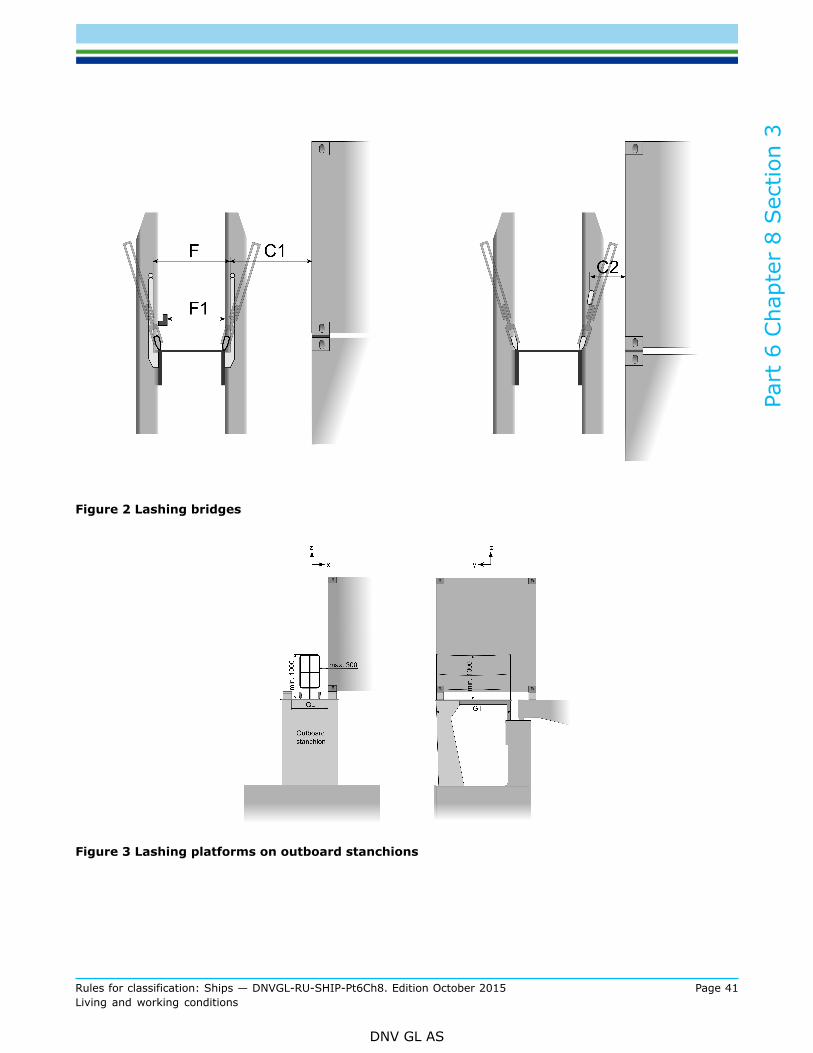
Part
6 C
hapt
er 8
Sec
tion
3
Rules for classification: Ships — DNVGL-RU-SHIP-Pt6Ch8. Edition October 2015 Page 41Living and working conditions
DNV GL AS
Figure 2 Lashing bridges
Figure 3 Lashing platforms on outboard stanchions

Part
6 C
hapt
er 8
Sec
tion
3
Rules for classification: Ships — DNVGL-RU-SHIP-Pt6Ch8. Edition October 2015 Page 42Living and working conditions
DNV GL AS
Figure 4 Work area between hatch covers
3.2.2 Transit area shall have anti-slip surfaces.
3.2.3 Walkways on deck shall be delineated by painted lines or otherwise marked by pictorial signs.
3.2.4 All protrusions in access ways in transit area, such as cleats, ribs and brackets that may constitute atrip hazard, shall be highlighted in a contrasting colour.
Guidance note:As far as practicable, access ladders and walkways should be free of permanent obstructions and designed so that workers do nothave to climb over piping.
---e-n-d---of---g-u-i-d-a-n-c-e---n-o-t-e---
3.3 Working area
3.3.1 Working areas shall be designed to eliminate the use of three-tier-high lashing bars and shall belocated in close proximity to securing equipment storage areas.
3.3.2 Working areas shall be designed to provide a clear space which is unencumbered by obstructions suchas deck piping, storage bins and guides to reposition hatch covers.
3.3.3 The horizontal distance from the lashing securing points to the containers shall not exceed 1100 mm,and not be less than 220 mm for lashing bridges and 130 mm for other positions. See Table 3, DimensionsC1, C2 and C3.For container bays with foundations designed for 40’ and 45’ container stowage, the dimension C1 may beincreased to 1300mm when measured to 40’ containers.
3.3.4 The width of working areas shall not be less than 750 mm. In addition, the width of permanentlashing bridges shall not be less than 750mm between top rails of fencing and shall provide a minimum cleardistance of 600 mm between stowage racks, lashing cleats and other obstructions. See Table 3, DimensionsA, GL, GT, I, F and F1.
3.3.5 Platforms shall be provided on the end of hatches and outboard lashing positions.

Part
6 C
hapt
er 8
Sec
tion
3
Rules for classification: Ships — DNVGL-RU-SHIP-Pt6Ch8. Edition October 2015 Page 43Living and working conditions
DNV GL AS
Guidance note:Platforms on the end of hatches and outboard lashing positions should be at the same level as the top of the hatch covers. The gapbetween such platforms and adjacent hatch covers should not exceed 90mm.
---e-n-d---of---g-u-i-d-a-n-c-e---n-o-t-e---
3.3.6 Working areas which contain removable sections shall be capable of being temporarily secured.
3.3.7 Working on the top of containers shall be avoided, e.g. through use of semi-automatic or fullyautomatic twistlocks.
3.3.8 Toe boards of 150 mm in height shall be provided around the sides of elevated working areas, toprevent securing equipment from falling and injuring people. In cases where toe board obstructs the stowageof containers, the height of toe board may be reduced to 100 mm.
Figure 5 Toe boards
3.4 Fencing design
3.4.1 Lashing bridges, platforms and other working area from which persons may fall 2.0 m or more shall beprovided with fencing satisfying the requirements given in [3.4.4].
3.4.2 Where openings in safety barriers are necessary to allow for container crane movements, removablefencing shall be provided.
3.4.3 Athwartships cargo securing walkways shall be protected by fencing satisfying the requirements givenin [3.4.4], if the edges of walkways are not protected when the hatch cover is removed.
3.4.4 Fencing shall have a minimum of three courses. The height of the uppermost course shall be at least1.0 m, measured from the base. The opening below the lowest course shall not exceed 230 mm. The othercourses shall not be more than 380 mm apart.A horizontal unfenced gap of fencing shall not be greater than 300 mm.
Guidance note:At positions where movable fencings are arranged due to stowage of containers, e.g., lashing platform above outboard stanchionsat 20’ container gap end, see Figure 3 for illustration, an alternative arrangement of the lower two courses may be accepted by theSociety on a case-by-case basis, taking position of container securing device into consideration.
---e-n-d---of---g-u-i-d-a-n-c-e---n-o-t-e---

Part
6 C
hapt
er 8
Sec
tion
3
Rules for classification: Ships — DNVGL-RU-SHIP-Pt6Ch8. Edition October 2015 Page 44Living and working conditions
DNV GL AS
Figure 6 Fencing
3.5 Access openings
3.5.1 Access openings in working area with a potential fall of 2.0 m or more shall be either protected byfencing in accordance with [3.4.4] or possible to be closed by access covers.
3.5.2 Access openings in transit area with a potential fall of 2.0 m or more shall be avoided, unless they areprotected by fencing in accordance with [3.4.4].
3.5.3 Access openings in working area and transit area shall be painted in contrasting colour around the rimof the openings.
3.5.4 Access openings at different levels of lashing bridges shall not be located directly below one another.
3.6 Ladders
3.6.1 Where a fixed ladder gives access to the outside boundary of a working area, the stringers shall beconnected at their extremities to the guardrails of the working area, irrespective of whether the ladder issloping or vertical. The stringers of shall also be opened above the working area level to give a minimumclear width of 700 mm to enable a person to pass through the stringers
3.6.2 Where a fixed ladder gives access to a working area through an opening in the working area,handholds extending at least 1.0 m above the working area shall be provided, to ensure safe access throughthe opening.
3.6.3 Fixed ladders shall not slope more than 25° from vertical. Where the slope of a ladder exceeds 15°from vertical, the ladder shall be provided with handrails positioned not less than 540 mm from the stringers,measured horizontally.
3.6.4 Fixed ladders shall provide a foothold at least 150mm deep.
3.6.5 Fixed ladders with a vertical height exceeding 3.0 m, and any fixed ladders from which a person mayfall into the cargo hold, shall be fitted with a safety cage satisfying the requirements given in [3.6.6] to[3.6.7].

Part
6 C
hapt
er 8
Sec
tion
3
Rules for classification: Ships — DNVGL-RU-SHIP-Pt6Ch8. Edition October 2015 Page 45Living and working conditions
DNV GL AS
3.6.6 The distance between the rungs and the back of the safety cage shall be minimum 750 mm. Safetycage hoops shall be uniformly spaced at intervals not exceeding 900 mm and be connected by vertical barsinside the hoop uniformly spaced around the circumference of the hoops.
3.6.7 The stringers shall be extended at least 1.0 m above the working area, and the ends of the stringersshall be given lateral support. The top step or rung shall be at the same level of the working area unlessrungs or steps are fitted up to the end of the stringers.
3.7 Container securing equipment arrangement
3.7.1 The lashing rod’s length in conjunction with the length and design of the turnbuckle shall be such thatthe need of extension is eliminated when lashing high cube (9’6”) containers.In the container securing arrangement document, typical lashing patterns for 9’6” containers shall be shown,if such containers are stowed on board.
Guidance note:Positively locked extensions, i.e., extensions positively locked to lashing rods before attached to containers, may be accepted.
---e-n-d---of---g-u-i-d-a-n-c-e---n-o-t-e---
3.7.2 During tightening or loosening motions on turnbuckles, the risk for hand injury shall be minimised,e.g., by keeping sufficient distance between turnbuckles.
Guidance note:During tightening or loosening motions, the distance between turnbuckles is typically not less than 45mm.
---e-n-d---of---g-u-i-d-a-n-c-e---n-o-t-e---
3.7.3 Storage bins shall be provided for container securing equipment.
3.8 Power supply
3.8.1 Reefer power outlets shall provide a watertight electrical connection.
3.8.2 Reefers shall be fitted with heavy-duty, interlocked and circuit-breaker protected electrical poweroutlets. This is in order to ensure that the outlet cannot be switched on until a plug is fully engaged and theactuator rod is pushed to the “on” position. Pulling the actuator rod to the “off” position shall manually de-energise the circuit.
3.8.3 Reefer power outlets shall de-energise automatically if the plug is accidentally withdrawn while in the“on” position. Furthermore, the interlock mechanism shall break the circuit while the pin and sleeve contactsare still engaged.
3.8.4 Reefer power outlets shall be positioned and designed so as not to require the operator to standdirectly in front of the socket when switching takes place.
3.8.5 The positioning of reefer power outlets shall allow for flexible cabling to be laid out without causing atripping hazard.
3.9 Lighting
3.9.1 Working areas and transit areas shall be provided with lighting.
3.9.2 The lighting shall be designed as a permanent installation adequately guarded against breakage.Guidance note:
Part
6 C
hapt
er 8
Sec
tion
3
Rules for classification: Ships — DNVGL-RU-SHIP-Pt6Ch8. Edition October 2015 Page 46Living and working conditions
DNV GL AS
Temporary lighting may be accepted by the Society on a case-by-case basis at locations where permanent lighting is not practical.
---e-n-d---of---g-u-i-d-a-n-c-e---n-o-t-e---
3.9.3 Light intensity levels shall not be less than 10 lux for transit area and 50 lux for working area.

DNV GLDriven by our purpose of safeguarding life, property and the environment, DNV GL enablesorganizations to advance the safety and sustainability of their business. We provide classification andtechnical assurance along with software and independent expert advisory services to the maritime,oil and gas, and energy industries. We also provide certification services to customers across a widerange of industries. Operating in more than 100 countries, our 16 000 professionals are dedicated tohelping our customers make the world safer, smarter and greener.
SAFER, SMARTER, GREENER