doc.: ieee 802.22-05/0108r0 · web view3.3.1 contention-based cdma bandwidth request .....25 3.3.2...
TRANSCRIPT

November 2005 doc.:IEEE 802.22-05/0108r0
IEEE P802.22Wireless RANs
WRAN PHY and MAC Proposal for TDD/FDD
Date: 2005-11-07
Author(s):Name Company Address Phone email
Chang-Joo Kim ETRI Korea +82-42-860-1230 [email protected]
Hak-Sun Kim Samsung Electro-mechanics Korea +82-31-210-3500 [email protected]
Joy Laskar Georgia Institute of Technology USA +1-404-894-5268 [email protected]
Abstract
Submission page 0 C.J.Kim/ETRI, H.S.Kim/SEM,J.Laskar/GT
This contribution presents PHY and MAC specifications for CR-enabled WRAN system. PHY is based on OFDMA and several features for incumbent service detection and channel move are proposed. It suggests that the existing MAC standard, especially IEEE 802.16 specification, be adopted as a baseline. Some CR-enabled features, including spectrum management, are introduced. Furthermore, CR-specific MAC management messages or information elements are proposed.
Notice: This document has been prepared to assist IEEE 802.22. It is offered as a basis for discussion and is not binding on the contributing individual(s) or organization(s). The material in this document is subject to change in form and content after further study. The contributor(s) reserve(s) the right to add, amend or withdraw material contained herein.
Release: The contributor grants a free, irrevocable license to the IEEE to incorporate material contained in this contribution, and any modifications thereof, in the creation of an IEEE Standards publication; to copyright in the IEEE’s name any IEEE Standards publication even though it may include portions of this contribution; and at the IEEE’s sole discretion to permit others to reproduce in whole or in part the resulting IEEE Standards publication. The contributor also acknowledges and accepts that this contribution may be made public by IEEE 802.22.
Patent Policy and Procedures: The contributor is familiar with the IEEE 802 Patent Policy and Procedures <http://standards.ieee.org/guides/bylaws/sb-bylaws.pdf>, including the statement "IEEE standards may include the known use of patent(s), including patent applications, provided the IEEE receives assurance from the patent holder or applicant with respect to patents essential for compliance with both mandatory and optional portions of the standard." Early disclosure to the Working Group of patent information that might be relevant to the standard is essential to reduce the possibility for delays in the development process and increase the likelihood that the draft publication will be approved for publication. Please notify the Chair <Carl R. Stevenson> as early as possible, in written or electronic form, if patented technology (or technology under patent application) might be incorporated into a draft standard being developed within the IEEE 802.22 Working Group. If you have questions, contact the IEEE Patent Committee Administrator at <[email protected]>.

November 2005 doc.:IEEE 802.22-05/0108r0
Co-Author(s):Name Company Address Phone email
Myung-Sun Song ETRI Korea +82-42-860-5046 [email protected] Jeon ETRI Korea +82-42-860-5947 [email protected]
Gwang-Zeen Ko ETRI Korea +82-42-860-4862 [email protected] Hwang ETRI Korea +82-42-860-1133 [email protected]
Soon-Soo Oh ETRI Korea +82-42-860-4974 [email protected] Kang ETRI Korea +82-42-860-5446 k [email protected]
Chung Gu Kang ETRI Korea +82-2-3290-3236 [email protected] Chang ETRI Korea +82-32-860-8422 [email protected]
Yoan Shin ETRI Korea +82-2-820-0632 [email protected] Hee Kim ETRI Korea +82-31-201-3793 [email protected] Lee ETRI Korea +82-31-201-2032 [email protected]
Moon Ho Lee ETRI Korea +82-63-270-2463 [email protected] Suk Lee Samsung Electro-mechanics Korea +82-31-210-3217 j [email protected] Chang Ho Lee Samsung Electro-mechanics Korea +82-31-210-3217 [email protected]
Kyutae Lim Georgia Institute of Technology USA +1-404-385-6008 [email protected]
Submission page 1 C.J.Kim/ETRI, H.S.Kim/SEM,J.Laskar/GT

November 2005 doc.:IEEE 802.22-05/0108r0
Table of Contents
1. Introduction ……………………………………………………………………………….. 32. PHY ………………………………………………………………………………………… 3
2.1 System Parameters for WRAN ………………………………………………………….. 32.2 Cognitive WRAN Transceiver Architecture ……………………………………….......... 42.3 PHY(Baseband) Architecture ……………………………………………………………. 52.4 OFDMA Symbol Time Structure and Parameters .............................................................. 52.5 Adaptive OFDMA With Flexible Bandwidth Allocation and Partial Spreading ............... 72.6 Frame Structure For TDD/FDD …………………………………………………………. 82.7 Subchannelization ………………………………………………………………………...102.8 Pilot Pattern ……………………………………………………………………………….112.9 Channel Coding And Modulation ……………………………………………………….. 112.10 Spectral Efficiency And Ideal Minimum Peak Throughput …………………………. ...122.11 Performance Analysis ………………………………………………………………….. 132.12 Ranging …………………………………………………………….…………………... 152.13 Proposed Spectrum Sensing Technique …………………………………………………15
2.13.1 Overview of proposed spectrum sensing technology ............................................................152.13.2 Coarse Spectrum Sensing – MRSS .........................................................................................152.13.3 Fine Spectrum Sensing – AAC ...............................................................................................18
3. MAC ………………………………………………………………………………………...213.1 MAC PDU format ………………………………………………………………………..21
3.1.1 User data ……………………………………………………………………………..213.1.2 MAC control message ……………………………………………………………….213.1.3 Packing and Fragmentation ………………………………………………………….223.1.4 MAC PDU and PHY Mapping …………………………………………………...….23
3.2 Scheduling Service and QoS ……………………………………………………………243.2.1 Uplink Scheduling Types …………………………………………………………….24
3.3 Bandwidth Request and Allocation .................................................................................253.3.1 Contention-based CDMA Bandwidth Request ............................................................253.3.2 Polling based bandwidth request .................................................................................26
3.4 MAC Support of PHY ........................................................................................................273.5 Network Entry and Initialization ........................................................................................273.6 CoS and QoS ......................................................................................................................28
3.6.1 Service and QoS requirement ......................................................................................293.7 Channel Management .........................................................................................................29
3.7.1 Transition diagram for channel set ..............................................................................303.7.2 Modification of DCD message ....................................................................................313.7.3 Down link frame prefix ...............................................................................................32
3.8 Channel Switching ..............................................................................................................323.8.1 Wide-area Switching Scenario .....................................................................................333.8.2 Local-area Switching Scenario ....................................................................................363.8.3 Channel Switching (DFS) Parameters .........................................................................373.8.4 MAC Messages for Channel Switching .......................................................................38
3.9 Radio Resource Management …………………………………………………………….383.9.1 Channel Grouping and Matching .................................................................................39
ReferencesAbbreviationsSubmission page 2 C.J.Kim/ETRI, H.S.Kim/SEM,J.Laskar/GT
November 2005 doc.:IEEE 802.22-05/0108r0
Technical Outlinefor the 802.22 WRAN Standard
1. IntroductionThe purpose of this document is to outline PHY and MAC specifications proposed for WRAN system.PHY is based on OFDMA for multiple access and FDD and TDD are proposed for duplex method. To
cope with WRAN channel condition and spectrum usage, the frame structure, subcarrier allocation scheme and pilot pattern, channel coding and modulation are proposed. Multi-Resolution Spectrum Sensing and Analog Auto-Correlation method are proposed for fast and low cost spectrum sensing. Specral efficiency, minimum peak data rate and BER simulation results are exhibited as performance analysis.MAC protocol specification is based on the existing MAC standard, especially IEEE 802.16
specification. Some CR-enabled features, including spectrum management, are introduced. Furthermore, CR-specific MAC management messages or information elements are proposed for modifying the current IEEE 802.16 specification as a baseline.
2. PHY
2.1 System Parameters for WRAN
Table 2-1 shows the system parameters for Wireless Regional Area Networks(WRANs). According to “Functional Requirements for 802.22 WRAN standard”, the frequency bands used by 802.22 systems vary from 54 MHz to 862 MHz. The typical range of the system is 33 km, and up to a maximum of 100 km. The required minimum peak throughput at edge of coverage shall be 1.5 Mbit/s per subscriber in the downlink and 384 kbit/s per subscriber in the uplink. A maximum and minimum spectrum efficiency are at least 5 bits/s/Hz and 0.5 bits/s/Hz, respectively. The mandatory channel spacings are 6, 7 and 8 MHz. In addition to, by using spectrum sensing result, bandwidth scalability can be provided from 1 MHz to 5 MHz. OFDM and adaptive OFDMA is chosen as a modulation and multiple access method. In adaptive OFDMA, it is possible to control the transmission parameters such as FFT size, GI mode, modulatiion, code rate, coding scheme, channel bandwidth, etc. The proposal can apply 2048, 4096, and 8192 FFT and 1/4, 1/8, 1/16, 1/32 cyclic prefix mode. In addition, cyclic postfix mode of 1/64 is used to combat the pre-cursor signal. The duplexing method shall be either TDD or FDD, but in license-exempt bands, TDD shall be used. The frame length is 5 ms or 10 ms for TDD and 5.103 ms or 10.206 ms for FDD.
Submission page 3 C.J.Kim/ETRI, H.S.Kim/SEM,J.Laskar/GT

November 2005 doc.:IEEE 802.22-05/0108r0
Table 2-1: System Parameters for WRAN
1/64Cyclic Postfix Mode
5 ms or 10 ms(TDD), 5.103 ms or 10.206 ms(FDD)Frame Length
1/4, 1/8, 1/16, 1/32Cyclic Prefix Mode
2048, 4096, 8192FFT Mode
Adaptive OFDMAMultiple Access
0.5 bits/s/Hz ~ 5 bits/s/HzSpectral Efficiency
Typical range 33 km, Maximum 60 kmService coverage
TDD or FDDDuplex
Default 4W EIRPTransmit power
1, 2, 3, 4, 5, 6, 7, 8 MHzBandwidth
Broadband access services such as ADSL, Cable MODEM(Internet, VoIP, Video conference, Bridged LAN service)
Target Services
Point-to-Multipoint NetworkNetwork topology
BPSK, QPSK, 16QAM, 64QAM, 256QAMModulation
Downlink 1.5 Mbps/subscriber, Uplink 384 kbps/subscriberMin. Data rate
54~862 MHzFrequency range
SpecificationParameters
2.2 Cognitive WRAN Transceiver Architecture
Figure 2-1 shows the cognitive WRAN transceiver architecture which is divided into two paths, i.e. data path and spectrum sensing path. Data path is composed of the directive antenna, switch(or duplexer), RF/IF part, PHY, and MAC. And spectrum sensing part is composed of omni antenna, correlator and low speed ADC.
Transmitter(RF/IF)
Receiver(RF/IF)
Coarse“MRSS”
Fine“AAC”
Low SpeedADC
PHY(Baseband)
MAC
SW orDuplexer
Sensing Receiver
Directive Antenna
Omni Antenna
* MRSS : Multi-Resolution Spectrum Sensing** AAC : Analog AutoCorrelation
Submission page 4 C.J.Kim/ETRI, H.S.Kim/SEM,J.Laskar/GT
November 2005 doc.:IEEE 802.22-05/0108r0
Figure 2-1 Cognitive WRAN Transceiver Architecture
2.3 PHY(Baseband) Architecture
The PHY block diagram for the downlink of an adaptive OFDMA system is shown in Figure 2-2. At transmitter, the binary data stream enters a randomizer. The randomizer output are then encoded and punctured, and bit-interleaved. The interleaved bits are then mapped into constellation symbols, which are subsequently allocated to subchannel. After being multiplexed with the preamble and pilot signal, the allocated subcarriers are combined using the IFFT into an OFDMA symbol. Finally a cyclic prefix and cyclic postfix are added to mitigate the intersymbol and intercarrier interference. This is then transmitted through a wireless and AWGN channel. The received signal is converted into a frequency domain signal using the FFT process after removing the cyclic prefix and cyclic postfix. After timing and frequency synchronization, the channel estimation can be performed using the preamble and pilot signal for coherent demodulation. The demodulated constellation symbols are then deallocated and demapped. And then through the deinterleaver and depuncturer, the demodulated signals enter channel decoder. Finally derandomizer recovers the binary data.
RandomizerEncoderPuncturer
&Interleaver
MapperSubcarrierAllocator S/ P
Preamble&
PilotInsertion
IFFTGuardInsertionP/ S
AWGN
Channel
De-randomizerDecoder
De-interleaver
&Depuncturer
De-mapper
SubcarrierDeallocator P/ SChannel
EstimationFFTGuardRemovalS/ P
Synchronization
BinaryData
RecoveredData
Figure 2-2. PHY(Baseband) Architecture
2.4 OFDMA Symbol Time Structure and Parameters
Figure 2-3 illustrates the OFDMA symbol time structure. Inverse Fast Fourier Transrom(IFFT) generates the useful OFDMA symbol Td. A copy of the last Tpre time of the useful OFDMA symbol time, termed cyclic prefix, is used to cope with the post-cursor signals, and a copy of the first Tpost time of the useful OFDMA
Submission page 5 C.J.Kim/ETRI, H.S.Kim/SEM,J.Laskar/GT
November 2005 doc.:IEEE 802.22-05/0108r0
symbol time, termed cyclic postfix, is used to cope with the pre-cursor signals. The guard interval time TG is the sum of the cyclic prefix time Tpre and cyclic postfix time Tpost. The pre- and post-cursor are shown in Figure 2-4.
TdTpre Tpost
Ts
TG=Tpre+Tpost
Figure 2-3. OFDM Symbol Time Structure
t0
post-cursorpre-cursor
Figure 2-4. Post- and Pre-cursor
For 2048, 4096, and 8192 FFT mode, Table 2-2 shows the OFDM parameters such as subcarrier spacing, number of used subcarrier, and OFDMA symbol time, etc. It is assumed that cyclic prefix mode is 1/4. To increase the robustness against frequency offset including Doppler effects, it is required to maximize the subcarrier spacing as possible. And to increase the data rate for given bandwidth, it is required to maximize the number of used subcarrier. The effective bandwidth of the transmitted signal is related to the subcarrier spacing and the number of used subcarriers. However it is required to consider a trade-off between ACI(adjacent channel interference) and bandwidth efficiency. The bandwidth efficiency is defined as,
where, Nused, f, and BW are the number of used subcarrier, subcarrier spacing, and bandwidth, respectively.The proposal uses the sampling factor of 8/7, thus the sampling rate is Fs=64/7 MHz(=8MHz*8/7).
Therefore the sampling frequency and subcarrier spacing are always constant for given FFT mode. In general, the bandwidth efficiency is designed to be in the range of 83–95% in order to occupy the maximum usable bandwidth but still allow adequate RF filtering. The bandwidth efficiency is chosen to be 92.93%.
Submission page 6 C.J.Kim/ETRI, H.S.Kim/SEM,J.Laskar/GT
November 2005 doc.:IEEE 802.22-05/0108r0
Table 2-2: OFDM Parameters
224 us112 us56 usCyclic Prefix Time(**)
1.116 kHz*832*k2.232 kHz*416*k4.464 kHz*208*kOccupied Bandwidth
1.116 kHz2.232 kHz4.464 kHz(***)Subcarrier Spacing
64/7 MHz64/7 MHz64/7 MHzSampling Frequency
832 * k416 * k208 * kNo. of Used Subcarrier
(including pilot but not DC)
OFDM Parameters
1134 us
14 us
896 us
92.93 %
8/7
k MHz(k = 1, 2, 3, 4, 5, 6, 7, 8)
8192 Mode
567 us283.5 usOFDMA Symbol Time
7 us3.5 usCyclic Postfix Time
448 us224 usFFT Time
92.93 %92.93 %Bandwidth Efficiency(*)
8/78/7Sampling Factor
k MHz(k = 1, 2, 3, 4, 5, 6, 7, 8)
k MHz(k = 1, 2, 3, 4, 5, 6, 7, 8)
BW
4096 Mode2048 ModeFFT Size
(*) Bandwidth Efficiency=Subcarrier Spacing*(Number of Used Subcarrier+1)/BW.(**) It is assumed that cyclic prefix mode is 1/4.(***) Italics indicate an approximated value.
2.5 Adaptive OFDMA with Flexible Bandwidth Allocation and Partial Spreading
In adaptive OFDMA system, there are many parameters that can be varied according to channel state information. The following parameters are frequently used in adaptive transmission systems.
Submission page 7 C.J.Kim/ETRI, H.S.Kim/SEM,J.Laskar/GT

November 2005 doc.:IEEE 802.22-05/0108r0
FFT parameters(FFT size, the ratio of GI time to FFT time, etc.) Modulation order(BPSK, QPSK, 16QAM, 64QAM, 256QAM) Code rate(1/2, 2/3, 3/4, 5/6, 7/8, etc.) Coding scheme(convolutional code, convolutional turbo code, LDPC code, concatenated code, etc.) Transmit power(power control, boosting factor, etc.)
In addition to, depending on the channel state information, the partial bandwidth can be used adaptively as shown in Figure 2-5. Here, the subcarrier spacing is the same for 1/2/3/4/5/6/7/8 MHz band, and common sampling frequency and FFT size for all bands is used. The flexible bandwidth can be allocated by adjusting the number of active subcarriers.
6 MHzf
Unused 2 MHz 8 MHz1 MHz
IncumbentUser
Figure 2-5. Flexible Bandwidth Allocation
2.6 Frame Structure for TDD/FDD
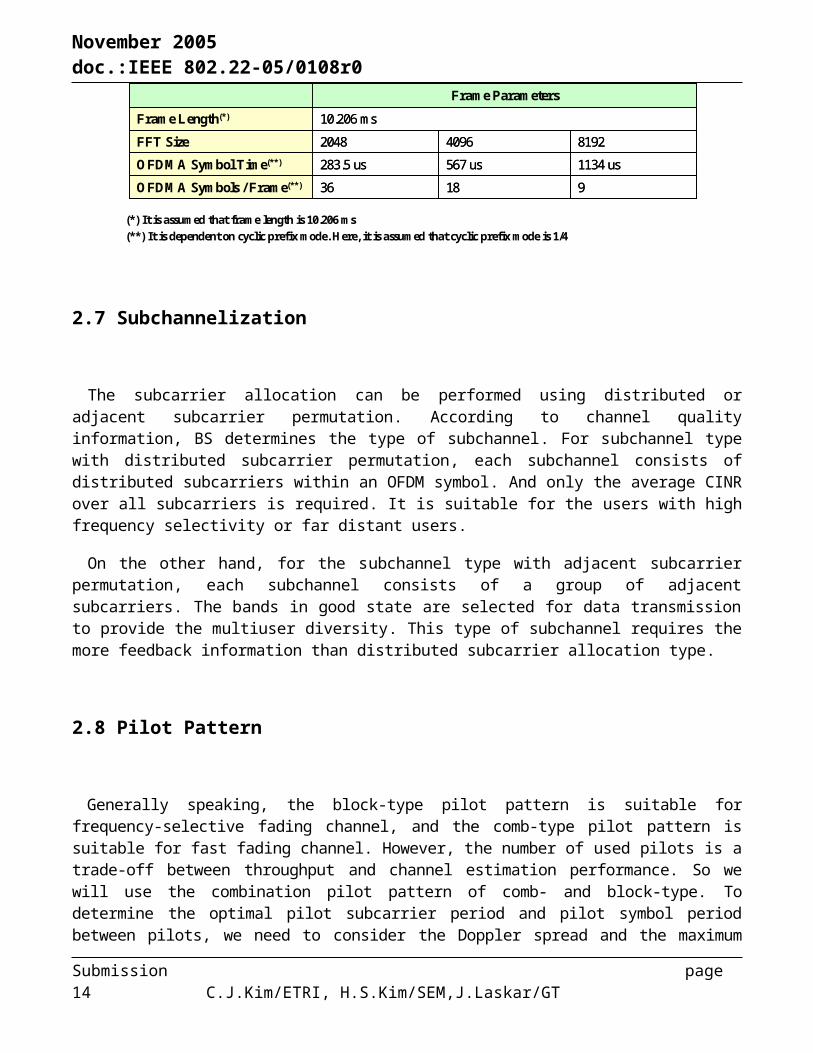
Figure 2-6 shows the frame structure for TDD system. Each frame begins with downlink preamble followed by a DL transmission and UL transmission. In each frame, the transition gap(TTG or RTG) shall be inserted at the end of each downlink and uplink transmission, respectively, to allow the BS to turn around. Where TTG and RTG denote transmit/receive transition gap and receive/transmit transition gap, respectively. The downlink FCH(Frame Control Header) contains the information regarding the current frame and DL-MAP. The DL-MAP message and UL-MAP message define the usage of the downlink burst and uplink burst, respectively. Table 2-3 shows the frame parameters for TDD system. It is assumed that the frame length is 10 ms and cyclic prefix mode is 1/4. From the point of view of a TTG time, the 2K and 4K FFT mode can be used to satisfy the typical range of the system(33 km), and the 8K FFT mode can be used to satisfy the maximum range of the system(100 km). The number of OFDMA symbols per frame depend on the cyclic prefix mode.
Figure 2-7 and Table 2-4 show the frame structure and frame parameter for FDD, respectively. In Table 2-4, it is assumed that the frame length is 10.206 ms and cyclic prefix mode is 1/4. Apart from the TTG and RTG time, the structure of FDD system is similar to that of TDD system.
Submission page 8 C.J.Kim/ETRI, H.S.Kim/SEM,J.Laskar/GT

November 2005 doc.:IEEE 802.22-05/0108r0
Frame #0 Frame #1 Frame #2 Frame #3 Frame #8(Frame #18)
Frame #9(Frame #19)
100 ms Superframe
10(5) ms Frame
Prea
mbl
e
DL Burst #3
Ranging
UL Control(ACK, CQI etc)
UL Burst #1
UL Burst #3
UL Burst #2
DL
DL Burst #1
DL Burst #2
DL Burst #4
ULTTG RTG
FCH
DLMAP
ULMAP
Figure 2-6. Frame Structure For TDD
Table 2-3: Frame Parameters for TDD
819240962048FFT Size
1134 us567 us283.5 usOFDMA Symbol Time(**)
< 42.5 km
40 us
321 us
17 (DL:UL=12:5)
< 128.4 km< 42.5 kmCell Coverage(***)
40 us40 us RTG Time
888 us321 us TTG Time
8 (DL:UL=6:2)34 (DL:UL=23:11)OFDMA Symbols / Frame(**)
10 msFrame Length(*)
Frame Parameters
819240962048FFT Size
1134 us567 us283.5 usOFDMA Symbol Time(**)
< 42.5 km
40 us
321 us
17 (DL:UL=12:5)
< 128.4 km< 42.5 kmCell Coverage(***)
40 us40 us RTG Time
888 us321 us TTG Time
8 (DL:UL=6:2)34 (DL:UL=23:11)OFDMA Symbols / Frame(**)
10 msFrame Length(*)
Frame Parameters
(*) It is assumed that frame length is 10 ms(**) It is dependent on cyclic prefix mode. Here, it is assumed that cyclic prefix mode is 1/4(***) Minimum TTG=round trip delay+tx to rx switching time, Minimum RTG=rx to tx switching time. It is
assumed that it takes 3.3 us for the waveform to reach 1 km and switching time is less than 40 us.
Submission page 9 C.J.Kim/ETRI, H.S.Kim/SEM,J.Laskar/GT

November 2005 doc.:IEEE 802.22-05/0108r0
Frame #0 Frame #1 Frame #2 Frame #3 Frame #8(Frame #18)
Frame #9(Frame #19)
102.06 ms Superframe
10.206(5.103) ms Frame
Prea
mble
DL Burst #3
Ranging
UL Control
UL Burst #1
UL Burst #3
UL Burst #2
DL
DL Burst #1
DL Burst #2
DL Burst #4
UL
or
FCH
DLMAP
ULMAP
Figure 2-7. Frame Structure For FDD
Table 2-4: Frame Parameters for FDD
819240962048FFT Size
1134 us 567 us 283.5 usOFDMA Symbol Time(**)
18 936OFDMA Symbols / Frame(**)
10.206 msFrame Length(*)
Frame Parameters
819240962048FFT Size
1134 us 567 us 283.5 usOFDMA Symbol Time(**)
18 936OFDMA Symbols / Frame(**)
10.206 msFrame Length(*)
Frame Parameters
(*) It is assumed that frame length is 10.206 ms(**) It is dependent on cyclic prefix mode. Here, it is assumed that cyclic prefix mode is 1/4
2.7 Subchannelization
The subcarrier allocation can be performed using distributed or adjacent subcarrier permutation. According to channel quality information, BS determines the type of subchannel. For subchannel type with distributed subcarrier permutation, each subchannel consists of distributed subcarriers within an OFDM symbol. And only
Submission page 10 C.J.Kim/ETRI, H.S.Kim/SEM,J.Laskar/GT

November 2005 doc.:IEEE 802.22-05/0108r0
the average CINR over all subcarriers is required. It is suitable for the users with high frequency selectivity or far distant users.
On the other hand, for the subchannel type with adjacent subcarrier permutation, each subchannel consists of a group of adjacent subcarriers. The bands in good state are selected for data transmission to provide the multiuser diversity. This type of subchannel requires the more feedback information than distributed subcarrier allocation type.
2.8 Pilot Pattern
Generally speaking, the block-type pilot pattern is suitable for frequency-selective fading channel, and the comb-type pilot pattern is suitable for fast fading channel. However, the number of used pilots is a trade-off between throughput and channel estimation performance. So we will use the combination pilot pattern of comb- and block-type. To determine the optimal pilot subcarrier period and pilot symbol period between pilots, we need to consider the Doppler spread and the maximum delay spread of the wireless channel under consideration. As the WRAN channel has the characteristics of the frequency-selective but slow fading, the pilot symbol spacing is sparse but the pilot subcarrier spacing is dense.
Figure 2-8 shows the pilot pattern with variable pilot symbol period and pilot subcarrier period. The pilots are placed at specified intervals in the OFDM frequency-time signal space, so that the frequency and time interpolation of the channel is used for the channel estimation. Pilot symbol period and pilot subcarrier period are varied with channel state information.
Pilot Symbol Period(variable)
Pilot
Subc
arrie
r Per
iod(v
ariab
le)
OFDMA Symbol Direction
Subc
arrie
r Dire
ctio
n
DataBoosted Pilot
Figure 2-8. Pilot Pattern
2.9 Channel Coding and Modulation
Submission page 11 C.J.Kim/ETRI, H.S.Kim/SEM,J.Laskar/GT

November 2005 doc.:IEEE 802.22-05/0108r0
Channel coding procedures consist of the randomization, channel encoding, and bit interleaving. Channel encoding scheme include the convolutional coding(CC), convolutional turbo conding(CTC), LDPC code, and concatenated code. For LDPC code, code rate of 1/2, 2/3, 3/4, 5/6, and 7/8 will be supported. For CTC, code rate of 1/3, 1/2, 2/3, 3/4, 5/6, and 7/8 will be supported. And for CC, code rate of 1/2, 2/3, 3/4, 5/6, and 7/8 will be supported. For concatenated code, BCH code is used as outer code and the inner code is chosen from among the CC, CTC, and LDPC code.
The preamble, pilot and control channel shall be modulated using BPSK. For data, Gray-mapped QPSK, 16QAM, 64QAM, and 256QAM shall be supported. The constellations shall be normalized by multiplying the constellation point with the specified factor to achieve the equal average power.
2.10 Spectral Efficiency and Ideal Minimum Peak Throughput
Table 2-5 shows the spectral efficiency of WRAN system. It is assumed that FFT size and cyclic prefix mode are 2048 and 1/4, respectively. The spectral efficiency is defined as,
where, Nused, bm, cr, Ts, and BW are the number of used subcarrier, the number of bits per modulation symbol, code rate, OFDMA symbol time, and bandwidth, respectively.
The WRAN system shall operate with a minimum spectral efficiency per transmission link of 0.5 bits/sec/Hz and a maximum goal of 5 bit/sec/Hz or better. From the Table 2-5, the proposal meets the spectral efficiency of the functional requirement.
Table 2-5: Spectral Efficiency
0.730.981.101.221.28QPSK
1.471.962.202.452.5716QAM
2.202.933.303.673.8564QAM
2.933.914.404.895.16256QAM
1/22/33/45/67/8Code Rate
Modulation
0.730.981.101.221.28QPSK
1.471.962.202.452.5716QAM
2.202.933.303.673.8564QAM
2.933.914.404.895.16256QAM
1/22/33/45/67/8Code Rate
Modulation
Unit : bps/Hz
Spectral Efficiency = No. of used subcarrier*code rate*no. of bits per modulation symbol/OFDM symbol time/BW
In Table 2-6, ideal minimum peak throughputs are shown for bandwidth of 6 MHz. It is assumed that there are no pilots and no sensing periods. And it is also assumed that there are at least 512 simultaneously associated CPEs and the oversubscription ratio is 50. Therefore, it can be assumed that at most 11 CPEs can be served by BS, simultaneously. The spectral efficiency is defined as,
Submission page 12 C.J.Kim/ETRI, H.S.Kim/SEM,J.Laskar/GT

November 2005 doc.:IEEE 802.22-05/0108r0
where, NCPEs is the number of CPEs that is served by BS simultaneously.The required minimum peak throughput of the WRAN system shall be 1.5 Mbit/s per CPE in down link and
384 kbit/s per CPE in the up link. From the Table 2-6, the proposal meets the minimum peak throughput of the functional requirement.
Table 2-6: Ideal Minimum Peak Throughput
0.400.530.600.670.70QPSK
0.801.071.201.331.4016QAM
1.201.601.802.002.1064QAM
1.602.132.402.672.80256QAM
1/22/33/45/67/8Code Rate
Modulation
0.400.530.600.670.70QPSK
0.801.071.201.331.4016QAM
1.201.601.802.002.1064QAM
1.602.132.402.672.80256QAM
1/22/33/45/67/8Code Rate
Modulation
Unit : Mbps
Throughput = No. of used subcarrier*code rate*no. of bits per modulation symbol/OFDM symbol time/no. of CPEs
2.11 Performance Analysis
Simulation result for code rate of 1/2 is shown in Figure 2-9. In this figure, the performances of LDPC code are compared with that of convolutional turbo code for variable modulation type. The simulation is performed using the WRAN multipath profile C. As the SNR increases the performance of LDPC code is better than that of convolutional turbo code. In addition, simulation result for code rate of 2/3 is shown in Figure 2-10. Similarly, as the SNR increases, the performance of LDPC code is better than that of convolutional turbo code. And as the H size increases, the performance of LDPC code is improved.
Submission page 13 C.J.Kim/ETRI, H.S.Kim/SEM,J.Laskar/GT
November 2005 doc.:IEEE 802.22-05/0108r0
0 5 10 15 20 2510
-10
10-8
10-6
10-4
10-2
100
Eb/No(dB)
BE
R
B lue1
Blue2
Red1
Red2 Blue1: 1/2Turbo message 728 bitsBlue2: 1/2Turbo message 1456 bitsRed1: 1/2LDPC H size 728*1456Red2: 1/2LDPC H size 1456*2912
Multi-path Fading6-PathsCarrier=617MHzDopper=0.10200 Frames
QPSK 16QAM 64QAM 256QAM
WRAN Channel profile C
Figure 2-9. Simulation result for code rate of 1/2 over multipath fading channel
5 10 15 20 25 3010
-7
10-6
10-5
10-4
10-3
10-2
10-1
100
E b/No(dB )
BE
R
Q P S K 16Q A M 64Q A M 256Q A M
B lue1
B lue2
Red1
Red2
B lue1:2/3Turbo m es s age bits 728B lue2:2/3Turbo m es s age bits 1456Red1:2/3 LDP C H s iz e 364*1092Red2:2/3 LDP C H s iz e 728*2184
M ult i-path fading6-P athsCarrier= 617M HzDopper= 0.10200 F ram es
WRAN Channel profile C
Figure 2-10. Simulation result for code rate of 2/3 over multipath fading channel
Submission page 14 C.J.Kim/ETRI, H.S.Kim/SEM,J.Laskar/GT

November 2005 doc.:IEEE 802.22-05/0108r0
2.12 Ranging
In OFDMA system, there are three types of ranging: initial ranging, periodic ranging, and bandwidth request. Initial ranging is used by any CPEs that want synchronization to the system channel for the first time. Periodic ranging processes are supported to synchronize the SS’s with the BS periodically during the normal operation. Bandwidth request mechanism is supported so that SS’s can request UL allocations for transmission of data to the BS.
2.13 Proposed Spectrum Sensing Technique
2.13.1 Overview of proposed spectrum sensing technology
This work suggests the spectrum sensing technique consisted of dual sensing stages – the coarse and the fine spectrum sensing as shown Figure 2-1. These two sensing stages collaborate with each other to enhance the accuracy of the spectrum detection performance. The coarse spectrum sensing technique adopted the wavelet transform to provide the multi-resolution sensing feature – Multi-Resolution Spectrum Sensing (MRSS). This feature realizes the flexible detecting resolution without any hardware burden increase. Meanwhile, the fine spectrum sensing exploits the periodic feature of the input signals unique for each modulation format or frame structure. This fine sensing technique uses the beneficial properties of the autocorrelation function – Analog Auto-Correlation (AAC). This fine sensing technique identifies the signal type and provides this information to MAC for the mitigation of interference effects. The suggested sensing techniques detect a variety of sophisticated signal formats adopted in the current and emerging wireless standards – the IS-95, WCDMA, EDGE, GSM, Wi-Fi, Wi-MAX, Zigbee, Bluetooth, digital TV (ATSC, DVB), and so on. Moreover, the analog implementation of these spectrum sensing techniques offers several advantages such as the fast detection for wideband frequency range, the low power consumption and the low hardware complexity. The following sections describe their principles of operation and performances in detail.
2.13.2 Coarse Spectrum Sensing – MRSS
The Fourier transform derives the spectral representation of the given time domain signal. The sinusoidal waveform is adopted as the basis function of the Fourier transform. The correlation between the given signal and this sinusoidal basis function stands for the spectral component of the corresponding signal for each carrier frequency. Meanwhile, the wavelet transform has various choices of the basis functions. Certain types of the wavelet basis functions may have the bandwidth, the carrier frequency and period as the freedom of design. The wavelet transform coefficient is the correlation of the given signal with the specific wavelet basis waveform. Therefore, by adjusting the wavelet pulse width and the carrier frequency, the spectral contents for the given signal can be represented with the scalable resolution or multi-resolution. Moreover, wavelet transform is able to analyze the spectral contents of the time-variant signals by changing these pulse width and frequency after maintaining them within certain interval.
Fig. 2-11 shows the conceptual picture to describe the trade-off between the time and the frequency resolution. The uncertainty inequality is applied to the selection of the wavelet waveform pulse width Wt and frequency width Wf, where
Submission page 15 C.J.Kim/ETRI, H.S.Kim/SEM,J.Laskar/GT

November 2005 doc.:IEEE 802.22-05/0108r0
2
2
22
222
6152
)]cos(1[1
)(1
p
p
t
p
p
dtttE
dttvtE
W
(Eq. 1)
3
sin)(2
1
)(2
1
2
2
22
22
222
p
pp
p
f
dE
djVE
W
(Eq. 2)The product of Wt and Wf has to be greater than equal 0.5, i.e. WtWf ≥ 0.5. The equality only holds when
the window pulse is the Gaussian pulse.
Time
Frequency
Wt
RMS Time-Frequency
Window
Amplitude
Wf
Wt Wt
Time Window
5.0ftWW
Figure 2-11. The conceptual picture to describe the trade-off between Wt and Wf.
The analog MRSS is suggested as the coarse spectrum sensing technique. The wavelet transform is applied to the input signal and the resulting coefficient values stand for the representation of the input signal’s spectral contents with the given detection resolution. Figure 2-12 shows the functional block diagram of the suggested MRSS technique. The building blocks consist of the analog wavelet waveform generator, the analog multiplier and the analog integrator for computing the correlation, and the low speed analog-to-digital signal converter (ADC) to digitize the calculated analog correlation values.
Submission page 16 C.J.Kim/ETRI, H.S.Kim/SEM,J.Laskar/GT

November 2005 doc.:IEEE 802.22-05/0108r0
X ADC
v(t)*ejwct
Driver Amp CLK#2
Signal Processing
Timing Clock
Wavelet Generator
CLK#1
x(t)
w(t)
z(t) y(t)X ADC
v(t)*ejwct
Driver Amp CLK#2
Signal Processing
Timing Clock
Wavelet Generator
CLK#1
x(t)
w(t)
z(t) y(t)
Figure 2-12. Functional block diagram of the suggested MRSS technique.
The wavelet pulse is generated and modulated with I-, Q-sinusoidal carrier with the given frequency. The correlations are calculated with the wavelet waveform with the given spectral width, i.e. the spectrum sensing resolution. By sweeping the local oscillator (LO) frequency with the certain interval, the signal power and the frequency values are detected over the spectrum range of interest. The resulting correlation with the I-, Q- components of the wavelet waveforms are digitized and their magnitudes are recorded. If these magnitudes are greater than the certain threshold level, the sensing scheme determines the meaningful interferer reception.
Since the analysis is performed in the analog domain, the high-speed operation and low-power consumption can be achieved. By applying the narrow wavelet pulse and the large tuning step size of LO, this MRSS is able to examine the very wide spectrum span in the fast and sparse manner. On the contrary, very precise spectrum searching is realized with the wide wavelet pulse and the delicate adjusting LO frequency. By virtue of the scalable feature of the wavelet transform, multi-resolution is achieved without any additional digital hardware burdens. Moreover, unlike the heterodyne-based spectrum analysis techniques, this MRSS technique does not need any physical filters for image rejection due to the band pass filtering effect of the window signal. Figure 2-13 shows the simulation results of the suggested MRSS performance applied to the wireless microphone (FM) signal.
0 0.2 0.4 0.6 0.8 1 1.2 1.4 1.6 1.8 2
x 106
-100
-80
-60
-40
-20
0
20
40
Frequency
Pow
er S
pect
rum
Mag
nitu
de (d
B)
0 0.2 0.4 0.6 0.8 1 1.2 1.4 1.6 1.8 2
x 106
-120
-110
-100
-90
-80
-70
-60
-50
Frequency (Hz)
PS
D (d
B)
(a) (b)Figure 2-13. The spectrum of (a) the wireless microphone (FM) signal and (b) the corresponding signal
spectrum detected with the MRSS technique.
Submission page 17 C.J.Kim/ETRI, H.S.Kim/SEM,J.Laskar/GT

November 2005 doc.:IEEE 802.22-05/0108r0
2.13.3 Fine Spectrum Sensing – AAC
Most of the communication signals have the periodic features, i.e. sinusoid carriers, periodic pulse trains, cyclic prefix, and preambles, etc. These features are unique for each signal type or frame/packet structure. Meanwhile, the correlation process derives the amount of the similarity between two signals. In other words, the correlation between the same waveforms produces the largest value. The data modulated waveform has random feature, since the original data are random values. Therefore, the correlation between the periodic signal waveform and the data modulated signal waveform can be ignored. Using this benefit of the correlation characteristics, the periodic feature of the given signal can be the signature for the specific signal type. The Analog Auto-Correlation (AAC) is proposed as the fine spectrum sensing technique. Figure 2-14 is the
functional block diagram of the suggested AAC technique. The building blocks are composed of the analog delay line, the analog multiplier, the analog integrator, the sliding window integrator, and low speed ADC to digitize the calculated analog correlation values.
November 2005
SEM/ETRI/Georgia Tech.Slide 8
doc.: IEEE 22-05-0000-00-0000
Submission
ACC Schematics
Multiplication Integratex(t)
Delay Td
Low SpeedADC
x(t-Td))Decision Making
FIR
Figure 2-14 The functional block diagram of the suggested AAC technique.
The input RF signal is delayed by the certain delay value . This delay value is predetermined and unique value for each signal format. The analog correlation between the original input signal and the corresponding delayed signal is performed by multiplying these two signals and integrating the resulting product. These correlation values are summed by the sliding-window integrator. When the resulting integrator output is greater than the certain threshold, the AAC sensing scheme determines the specific signal type for the input signal.This AAC technique processes all the signals in the analog domain. This feature enables the real-time
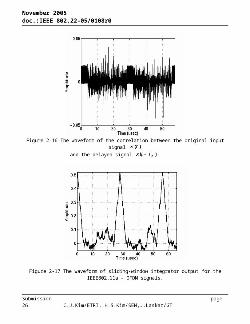
operation and the low power consumption. By applying delay and correlation to the input signal, the blind detection is achieved with no need of any known reference signals. This blind detection drastically reduces the hardware burden and the power consumption for the reference signal recovery. Moreover, the AAC technique enhances the spectrum sensing performance with the collaboration with the MRSS technique. Once the MRSS detects the suspicious interferer signal reception, the AAC examines the unique feature for the signal and identifies its specific signal type.In order to show the proof of the concept, a computer simulation was performed for the OFDM signal. This
signal has the synchronization preambles at the beginning of the frame structure. For the simplicity, only one data OFDM symbol is followed by the preamble. Figure 2-15 (a) and (b) show the waveform and the spectrum of the input OFDM signal to be detected with the proposed AAC technique.
Submission page 18 C.J.Kim/ETRI, H.S.Kim/SEM,J.Laskar/GT

November 2005 doc.:IEEE 802.22-05/0108r0
(a) (b)
Figure 2-15 OFDM signal; (a) the waveform and (b) the spectrum.
Figure 2-16 shows the waveform of the correlation between the original input signal and the delayed signal . The resulting correlation waveform has the consecutive positive values for the preambles. Then, the result of the sliding-window integration has the peaks for the preamble locations within the OFDM frame structure. Meanwhile, the correlation of the modulated data symbols has the random values and can be ignored after the sliding-window integration. By monitoring the periodic nature of the output signal, shown in Figure 2-17, type of the input signal can be determined.
Submission page 19 C.J.Kim/ETRI, H.S.Kim/SEM,J.Laskar/GT

November 2005 doc.:IEEE 802.22-05/0108r0
Figure 2-16 The waveform of the correlation between the original input signal and the delayed signal .
Figure 2-17 The waveform of sliding-window integrator output for the IEEE802.11a – OFDM signals.
Submission page 20 C.J.Kim/ETRI, H.S.Kim/SEM,J.Laskar/GT

November 2005 doc.:IEEE 802.22-05/0108r0
3. MAC
This document introduces key feature of proposed MAC layer. The main is based on the IEEE 802.16d MAC specification. CR-enabled MAC features are added to this main MAC specification. For channel management, CR-specific channel sets that consist of active, candidate, occupied,
disallowed and null sets are defined. Channel switching procedures and related MAC management messages are also specified. For interference avoidance, proposed avoidance mechanism uses implicit signaling to support distributed (cooperative) sensing without any control channel. For Radio resource management, to maximize the average system throughput, we proposed channel matching and grouping schemes based on the condition of CPE’s channel.
3.1 MAC PDU format
3.1.1 User data
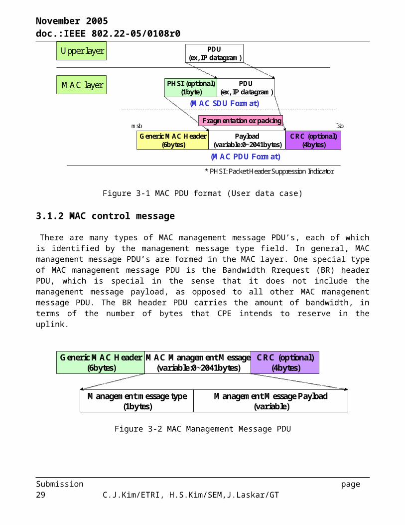
There are three different types of MAC PDUs which are one for user data from upper layer (e.g., IP datagram), MAC management PDU (see Section 3.1.2), and bandwidth request header PDU (see Section 3.1.2). Each PDU packet can be fragmented or multiple PDU packets are packed to form a MAC PDU in the MAC layer. Each MAC PDU is uniquely identified with the generic MAC header of 6 bytes, which include a connection ID. The generic MAC header is coded by its own error detection code, HCS (header check sequence). Meanwhile, each MAC PDU can be error-checked with optional CRC.
Generic MAC Header(6bytes)
Payload(variable:0~2041bytes)
CRC (optional)(4bytes)
lsb
PHSI (optional)(1byte)
PDU(ex, IP datagram)
(MAC SDU Format)
* PHSI: Packet Header Suppression Indicator
PDU(ex, IP datagram)
msb
(MAC PDU Format)
Fragmentation or packing
MAC layer
Upper layer
Figure 3-1 MAC PDU format (User data case)
3.1.2 MAC control message
There are many types of MAC management message PDU’s, each of which is identified by the management message type field. In general, MAC management message PDU’s are formed in the MAC layer. One special type of MAC management message PDU is the Bandwidth Rrequest (BR) header
Submission page 21 C.J.Kim/ETRI, H.S.Kim/SEM,J.Laskar/GT

November 2005 doc.:IEEE 802.22-05/0108r0
PDU, which is special in the sense that it does not include the management message payload, as opposed to all other MAC management message PDU. The BR header PDU carries the amount of bandwidth, in terms of the number of bytes that CPE intends to reserve in the uplink.
Management message type(1bytes)
Management Message Payload(variable)
Generic MAC Header(6bytes)
MAC Management Message(variable:0~2041bytes)
CRC (optional)(4bytes)
Figure 3-2 MAC Management Message PDU
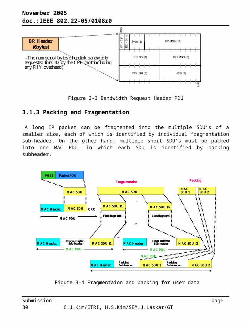
BR Header(6bytes)
- The number of bytes of uplink bandwidth requested for CID by the CPE (not including any PHY overhead)
Figure 3-3 Bandwidth Request Header PDU
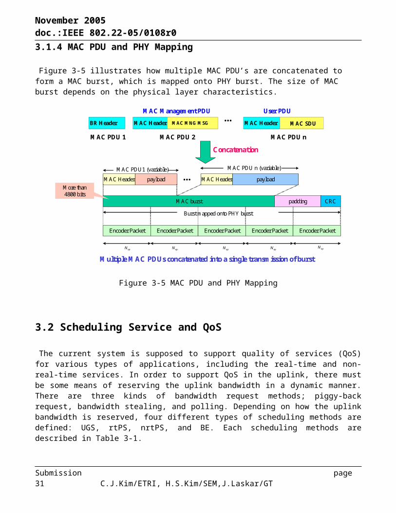
3.1.3 Packing and Fragmentation
A long IP packet can be fragmented into the multiple SDU’s of a smaller size, each of which is identified by individual fragmentation sub-header. On the other hand, multiple short SDU’s must be packed into one MAC PDU, in which each SDU is identified by packing subheader.
Submission page 22 C.J.Kim/ETRI, H.S.Kim/SEM,J.Laskar/GT

November 2005 doc.:IEEE 802.22-05/0108r0
Packet PDUPHSI
MAC SDUMAC SDU 1
MAC SDU 2
PackingSub-header
MAC Header MAC SDU CRC
MAC Header MAC SDU 1
MAC SDU f1 MAC SDU fn
PackingSub-header MAC SDU 2
FragmentationSub-headerMAC Header MAC SDU f1
FragmentationSub-headerMAC Header MAC SDU f2
MAC PDU MAC PDU
MAC PDU
MAC PDU
Fragmentation Packing
MAC SDU
First fragment Last fragment
…
…
…
Figure 3-4 Fragmentaion and packing for user data
3.1.4 MAC PDU and PHY Mapping
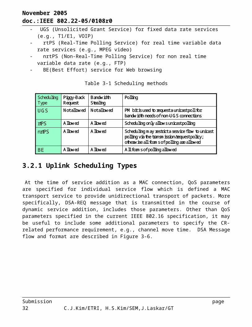
Figure 3-5 illustrates how multiple MAC PDU’s are concatenated to form a MAC burst, which is mapped onto PHY burst. The size of MAC burst depends on the physical layer characteristics.
MAC Header
MAC PDU 1
MAC MNG MSG
MAC Header payload MAC Header payload
MAC PDU1 (variable) MAC PDU n (variable)
MAC burst padding CRC
Burst mapped onto PHY burst
Encoder Packet Encoder Packet Encoder Packet Encoder Packet Encoder Packet
epN epN epN epN epN
More than 4800 bits
BR Header
MAC PDU 2
MAC Header MAC SDU
MAC PDU n
…
Concatenation
…
Multiple MAC PDUs concatenated into a single transmission of burst
User PDUMAC Management PDU
Figure 3-5 MAC PDU and PHY Mapping
Submission page 23 C.J.Kim/ETRI, H.S.Kim/SEM,J.Laskar/GT

November 2005 doc.:IEEE 802.22-05/0108r0
3.2 Scheduling Service and QoS
The current system is supposed to support quality of services (QoS) for various types of applications, including the real-time and non-real-time services. In order to support QoS in the uplink, there must be some means of reserving the uplink bandwidth in a dynamic manner. There are three kinds of bandwidth request methods; piggy-back request, bandwidth stealing, and polling. Depending on how the uplink bandwidth is reserved, four different types of scheduling methods are defined: UGS, rtPS, nrtPS, and BE. Each scheduling methods are described in Table 3-1.
- UGS (Unsolicited Grant Service) for fixed data rate services (e.g., T1/E1, VOIP)- rtPS (Real-Time Polling Service) for real time variable data rate services (e.g., MPEG video)- nrtPS (Non-Real-Time Polling Service) for non real time variable data rate (e.g., FTP)- BE(Best Effort) service for Web browsing
Table 3-1 Scheduling methods
All forms of polling allowedAllowedAllowedBE
Scheduling may restrict a service flow to unicast polling via the transmission/request policy; otherwise all forms of polling are allowed
AllowedAllowednrtPS
Scheduling only allows unicast pollingAllowedAllowedrtPS
PM bit is used to request a unicast poll for bandwidth needs of non-UGS connections
Not allowedNot allowedUGS
PollingBandwidth Stealing
Piggy-Back Request
Scheduling Type
3.2.1 Uplink Scheduling Types
At the time of service addition as a MAC connection, QoS parameters are specified for individual service flow which is defined a MAC transport service to provide unidirectional transport of packets. More specifically, DSA-REQ message that is transmitted in the course of dynamic service addition, includes those parameters. Other than QoS parameters specified in the current IEEE 802.16 specification, it may be useful to include some additional parameters to specify the CR-related performance requirement, e.g., channel move time. DSA Message flow and format are described in Figure 3-6.
Submission page 24 C.J.Kim/ETRI, H.S.Kim/SEM,J.Laskar/GT

November 2005 doc.:IEEE 802.22-05/0108r0
Service Flow Scheduling Type11
Maximum Latency14Tolerated Jitter13……..
Minimum Tolerable Traffic Rate10Minimum Reserved Traffic Rate9Maximum Traffic Burst8Maximum Sustained Traffic Rate7Traffic Priority6……..
ParameterType
Service Flow Scheduling Type11
Maximum Latency14Tolerated Jitter13……..
Minimum Tolerable Traffic Rate10Minimum Reserved Traffic Rate9Maximum Traffic Burst8Maximum Sustained Traffic Rate7Traffic Priority6……..
ParameterType
- DSA-REQ Message
0: Reserved1: for Undefined2: for BE (default)3: for nrtPS4: for rtPS5: Reserved6: for UGS7-255: Reserved
1
ValueLength0: Reserved1: for Undefined2: for BE (default)3: for nrtPS4: for rtPS5: Reserved6: for UGS7-255: Reserved
1
ValueLength
- Dynamic Service AdditionMAC Header (Primary Management CID)
Management Message Type = 11Transaction ID
6 bytes1 byte2 bytes
Type = 1 variable
variable
Length Value
Type = 11 Length ValuevariableType = xx Length Value
BSCPE
DSA-REQ
DSA-RVD
DSA-RSP
DSA-ACK
BSCPE
DSA-REQ
DSA-RVD
DSA-RSP
DSA-ACK
Figure 3-6 Dynamic Service Addition message flow and format
3.3 Bandwidth Request and Allocation
Because the uplink burst profile can be changed dynamically, all requests for bandwidth shall be made in terms of the number of bytes needed to carry the MAC header and payload. The Bandwidth Request message can be transmitted during any uplink allocation, except during any initial ranging interval.
The IEEE 802.16-OFDMA PHY supports two mandatory contention-based Bandwidth Request meshanisms: The CPE shall either send the bandwidth request header or use the CDMA-based mechanism as specifed in the following Section.
3.3.1 Contention-based CDMA Bandwidth Request
The current IEEE 802.16 MAC system supports dynamic reservation-based multiple access. In other words, bandwidth must be requested by individual CPE in terms of the number of bytes to be reserved in the uplink. A ranging code, which is a segment of PN sequence, is randomly selected and transmitted in a randomly selected slot for bandwidth request. Unless the same code and same slot are selected by more than one CPE, the corresponding bandwidth request will be successfully transmitted without collision. The random access region in the uplink is specified by the parameters in CDMA_Allocation_IE.
Submission page 25 C.J.Kim/ETRI, H.S.Kim/SEM,J.Laskar/GT
November 2005 doc.:IEEE 802.22-05/0108r0
BSCPE
Transmit randomly selected Request code in a randomly selected Ranging Slot
Request Code[Receive Request Code]
Send UL-MAP with predefined slots allocated to the CPE and indication of Request Code and Ranging Slot
UL-MAP Receive UL MAP message with Request Codeand Ranging Slot matching sent values and upstream allocation information
Upstream Burst [Allocated Time Symbol Time]Transmit packet or Bandwidth Request
[Receive Upstream Burst]
Figure 3-7 Contention-based CDMA Bandwidth Request Mechanism
Table 3-2 CDMA_Allocation_IE
Shall be set to zero1 bitreserved }
1=yes, 0=no1 bitBW request mandatory
6 bitsRanging subchannel
10 bitsRanging Symbol
6 bitsRanging Code
8 bitsDuration
CDMA_Allocation_IE() {
NotesSizeSyntax
Shall be set to zero1 bitreserved }
1=yes, 0=no1 bitBW request mandatory
6 bitsRanging subchannel
10 bitsRanging Symbol
6 bitsRanging Code
8 bitsDuration
CDMA_Allocation_IE() {
NotesSizeSyntax
3.3.2 Polling based bandwidth request
The uplink bandwidth that is required for bandwidth request is allocated by polling process. The bandwidth is allocated by BS implicitly for individual CPE or a multicast group of CPE’s. Once polled, a corresponding CPE transmits the bandwidth request (BR) message in the given region and then, the allocation result is informed in MAP on the downlink. When a CPE is polle individually, no explicit message is transmitted to poll the CPE. The CPE is allocated bandwidth sufficient to respond with a BW Request. This type of BW request is called Unicast polling. However, if insufficient bandwidth is available to individually poll many inactive CPEs, some CPEs may be polled in multicast groups or a broadcast poll may be issued. This type of BW request is called Multicast polling. Both polling mechanisms are depicted in Figure 3-8.
Submission page 26 C.J.Kim/ETRI, H.S.Kim/SEM,J.Laskar/GT
November 2005 doc.:IEEE 802.22-05/0108r0
BS
CID #1CID #2
….CID #n
BR(# of Bytes,CID)
MAP(Allocation,CID)CID #1CID #2
….CID #n
Implicit Polling Scheduler
Scheduler
CPECID #1CID #2
….CID #n
BR(# of Bytes,CID)
MAP(Allocation,CID)CID #1CID #2
….CID #n
Implicit Polling Scheduler
Scheduler
CPE
- Unicast Polling
Implicit polling Data Grant IE(Basic CID) CPE polled individually
CID #1CID #2
….CID #n
BR(# of Bytes,CID)
MAP(Allocation,CID)CID #1CID #2
….CID #n
Implicit Polling Scheduler
Scheduler
CPEBS- Multicast/Broadcast Polling
Implicit polling Bandwidth Request(Multicast CID) Some CPEes polled in multicast groups
Figure 3-8 Unicast polling vs multicast/broadcast polling
3.4 MAC Support of PHY
Figure 3-9 is the typical OFDMA frame structure for TDD mode. Each frame lasts for 10ms (or optionally for 5ms). There are 10 frames in each superframe (or 20 frames, depending on the frame duration). The first frame of each superframe is used for sensing, e.g., quiet period. Frame control section includes the information field for channel grouping and matching required for cognitive radio operation.
- Initial ranging region - BR/Periodic ranging region
-CQI channel region- UL_MAP allocation- DL burst allocation
- Frame control- Band grouping /
matching
- UL burst allocation
FCH
UL Control (ACK,..)
DL-MAP
TTG
Prea
mbl
e
RTGDL UL
Ranging
UL-MAP
Frame #0 Frame #1 Frame #2Frame # 9
(#19)Frame #3Frame #8
(#18)
100 ms superframe10 (5) ms
DL Bursts #1 DL Bursts #2
DL Bursts #3
DL Bursts #4
UL Bursts #0
UL Bursts #1
UL Bursts #2
Figure 3-9 Frame structuere and its functions in TDD mode
3.5 Network Entry and Initialization
Submission page 27 C.J.Kim/ETRI, H.S.Kim/SEM,J.Laskar/GT

November 2005 doc.:IEEE 802.22-05/0108r0
When CPE is turned on, initialization is performed to search for its own active set 1. While scanning a downlink channel out of all possible channels, preamble is used to establish the downlink synchronization, which subsequently allows for obtaining the DCD and DL-MAP. Furthermore, uplink parameters, e.g., UCD and UL-MAP, are obtained. Ranging process is performed to adjust timing, power, and offset frequency adjustments. In the course of ranging, basic CID & primary CID are allocated. After the ranging process is completed, IP connectivity is established. The corresponding uplink channel is specified in the UCD. Once active set 1 is established, all other channel sets, e.g., candidates and occupied sets, must be identified and updated via the current active set 1 for CR-enabled operation. Entire initialization procedure is shown in Figure 3-10..
Figure 3-10 Network initialization procedure
3.6 CoS and QoS
Four different service classes are defined as shown in Table 3-3: UGS, rt-VBR, nrt-VBR, and BE. Each service class is characterized by a set of QoS parameters. For the uplink bandwidth allocation, the different uplink scheduling service is applicable to the different service class.
Submission page 28 C.J.Kim/ETRI, H.S.Kim/SEM,J.Laskar/GT
November 2005 doc.:IEEE 802.22-05/0108r0
Table 3-3 Service calsses and their QoS parameters
BE
nrt-VBR
rt-VBR
UGS
Data DeliveryServices
- Max. sustained traffic rate- Traffic priority- Request/Transmission policy
- Min. reserved traffic rate- Max. sustained traffic rate- Traffic priority- Request/Transmission policy
- Maximum latency- Min. reserved traffic rate- Max. sustained traffic rate- Traffic priority- Request/Transmission policy- Unsolicited polling Interval
- Tolerated jitter- SDU size- Min. reserved traffic rate- Max. latency- Request/Transmission policy- Unsolicited grant interval
QoSParameters
Data streams for which no minimum service level is required and therefore may be handled on a space-available basis
Delay-tolerant data streams consisting of variable-sized data packets for which minimum data rate is required
Real-time service flows that generate variable-sized data packets on a periodic basis
Real-time data streamsconsisting of fixed-size data packets issued at periodic intervals
Definition
UGS- T1/E1- VoIPwithout
silence suppression
rtPS- Streaming Video
BE- HTTP- Instant Messenger
nrtPS- FTP (Download)
nrtPS- VoIPwith silencesuppression
Scheduling Services Applications
3.6.1 Service and QoS requirement
The QoS/CoS requirements can be met with appropriate bandwidth assignment in the scheduler of BS. However, these requirements are too stringent as compared with the performance requirements specified for DFS parameters.
Table 3-4 QoS requirement
20msBER 10^-6Time Critical Packet
40msBER 10^-4Standard Quality
Telephony
20msBER 10^-6Full Quality Telephony
(Vocoder MOS)
Maximum LatencyDelay (One way)
Maximum RatioService
20msBER 10^-6Time Critical Packet
40msBER 10^-4Standard Quality
Telephony
20msBER 10^-6Full Quality Telephony
(Vocoder MOS)
Maximum LatencyDelay (One way)
Maximum RatioService
3.7 Channel Management
Submission page 29 C.J.Kim/ETRI, H.S.Kim/SEM,J.Laskar/GT
November 2005 doc.:IEEE 802.22-05/0108r0
For efficient channel management in the course of the cognitive radio operations, four different channel sets are defined: active set 1, active set 2, candidate set, occupied set, and null set. These sets are respectively maintained in BS and CPE while they are updated in every quiet period. Note that a set of channels that do not belong to either active set 1, active set 2, candidate set or occupied set is defined as a null set and it is maintained only the BS. Each channel set is defined as follows:
- Active set 1: a set of used channels for a certain CPE - Active set 2: a set of used channels for a certain BS- Candidate set: a set of five clean channels available for a certain CPE or BS- Occupied set: a set of occupied channels by incumbent user which a certain CPE finds - Disallowed Set: a set of channels whose access are not allowed by regulation- Null set: a set of channels that are not classified as one of above five sets
Note that the allowed set is defined by union of candidate set and null set depending on channel’s SIR level. Also disallowed set is not considered in channel management senarios because it changes not frequently.
In order to maintain the channel sets, each BS maintains five channel sets (i.e., Active 1, Active 2, Occupied, Candidate, and Null). Also, each CPE maintains four channel sets (i.e., Active 1, Active 2, Candidate, and Occupied). These individual sets are updated in every interval of quiet period either at a fixed interval or aperiodic interval.
3.7.1 Transition diagram for channel set Any channel belongs to one of possible channel sets in the BS. At the end of quiet period, it may transit
to other set as shown by the state transition diagram. Depending on the activities of incumbent users and channel quality, 7 possible transitions can be observed as shown in Figure 3-11. The condition for each transition is described as follows:
Submission page 30 C.J.Kim/ETRI, H.S.Kim/SEM,J.Laskar/GT
November 2005 doc.:IEEE 802.22-05/0108r0
Null Set
Active Set
Occupied SetCandidate Set1
1
2
75
6
46 13
Figure 3-11 Channel state transition diagram
1. The channel becomes useless as incumbent service appears.
2. Incumbent service releases the channel, but classified as a member of candidate set as quality goes above a given threshold.
3. Incumbent service releases the channel, but classified as a member of null set as quality goes below a given threshold.
4. The channel is classified as a member of candidate set as quality goes above a given threshold.
5. The channel becomes active as quality goes above a given threshold.
6. The channel is classified as a member of null set as quality goes below a given threshold.
7. The channel is released due to the finish of its usage.
3.7.2 Modification of DCD message
BS must always keep track of the channel sets all CPE’s, which is broadcast to all CPE’s via DCD [Downlink Channel Descriptor] in a periodic manner. DCD is one of MAC management messages that record the physical layer features used in the system, including the channel information. As the channel ID of the candidate set must be specified for individual CPE, DCD includes such specification in its information field. In a typical operation, DCD is transmitted at a period of a few seconds. Submission page 31 C.J.Kim/ETRI, H.S.Kim/SEM,J.Laskar/GT
November 2005 doc.:IEEE 802.22-05/0108r0
Table 3-5 Modification in DCD
Note
To specify the channel IDs of the candidate set for individual CPE
To specify occupied set channel IDs
To specify active set 2 channel IDs
To specify all channels that CR-BS can use
Number of DL Channels
for (i=1; Number of CPEs) {
(CPE_ID, channel ID)
for (i=1; Number of occupied set channels) {
Channel ID}
for (i=1; Number of active set 2 channels) {
Channel ID}
Number of occupied set channels
for (i=1; Number of DL Channels) {
Channel ID }
Number of active set 2 channels
Number of CPEs
………
………………
}}
Field Note
To specify the channel IDs of the candidate set for individual CPE
To specify occupied set channel IDs
To specify active set 2 channel IDs
To specify all channels that CR-BS can use
Number of DL Channels
for (i=1; Number of CPEs) {
(CPE_ID, channel ID)
for (i=1; Number of occupied set channels) {
Channel ID}
for (i=1; Number of active set 2 channels) {
Channel ID}
Number of occupied set channels
for (i=1; Number of DL Channels) {
Channel ID }
Number of active set 2 channels
Number of CPEs
………
………………
}}
Field
3.7.3 Downlink frame prefix
The active set 1 must be notified to all CPE’s in the cell. As it must be updated as frequently as possible, the active set 1 information is broadcast in the separate channel, rather than specified in the DCD. In the proposed system, DL_Frame prefix can be used for updating the active set 1 for each CPE. Just
for ease of radio resource management as discussed in Section 10, active set 1 for each CPE is managed by a channel group. A group is defined as a set of CPE’s which share the same channel and it is uniquely identified by a
group ID. In other words, each group is associated with the uplink and downlink channels. Every time a group membership is changed, it is indicated by group change indication bit in the DL_Frame prefix. Furthermore, membership of each group is individually updated in the DL_Frame prefix as a CPE leaves or joins the group. Note that all CPE’s in the cell must always hear the DL_Frame prefix to keep track of their active set 1
information. Multiple groups can be formed by a channel grouping procedure in the radio resource management function.
Table 3-6 DL_Frame Prefix
Submission page 32 C.J.Kim/ETRI, H.S.Kim/SEM,J.Laskar/GT

November 2005 doc.:IEEE 802.22-05/0108r0
……….
}DL_MAP length
All DL frames broadcast the same information
1: join0: leaveStatus }
Primary CID CPE CID
Group change information length
UL channel IDDL channel ID
1: group change0: no change
Note
Group ID
Number of CPEs_to_update
Group change indication
Number of groupsfor (i=1; Number of groups) {
for (i=1; Number of CPEs_to_update) {
Field
3.8 Channel Switching
Herein, “channel switching” refers to the operation of selecting a new channel in the event of appearance of incumbent user (IU). There are two types of channel switching: wide-area switching and local-area switching. Wide-area switching is executed when appearance of IU is detected by both all CPE’s and BS and thus, all of them must move to the new clean channel. Meanwhile, local-area switching is executed when appearance of IU is detected by some of CPE’s (i.e., detected locally). Note that local-area switching is supported only in the multi-FA system while wide-area switching is supported by both single FA- and multi-FA systems.All CPE’s report their interference conditions detected during the quiet period to BS via Scan Response
message. In the event that appearance of IU is detected by CPE, then Scan Response message must not be transmitted, simply because it merely interferes with the IU. The BS can find that the corresponding CPE experiences the interference with IU, only by not receiving the Scan Response message within a time-out interval. For example, appearance of IU can be implicitly known to BS in case that the Scan Response message is not received for the given number of times. This is the implicit interference detection process employed in the proposed protocol. For the interference in the downlink, however, the implicit detection method is not complete unless it is determined whether either uplink or downlink is subject to interference. In this case, some periodic signaling in the uplink, e.g., periodic ranging process or CQI report, must be monitored to ensure that the uplink is alive while the downlink is interfered.
Table 3-7 Wide and local area switching
Submission page 33 C.J.Kim/ETRI, H.S.Kim/SEM,J.Laskar/GT

November 2005 doc.:IEEE 802.22-05/0108r0
No Scan response received & interference zone estimated
Local switching
No Scan response receivedWide-area switchingUplink
No MAP received in the downlink and Period ranging/CQI report alive in the uplink
Wide-area switching
Downlink
Detection methodSwitching type Interference Type
No Scan response received & interference zone estimated
Local switching
No Scan response receivedWide-area switchingUplink
No MAP received in the downlink and Period ranging/CQI report alive in the uplink
Wide-area switching
Downlink
Detection methodSwitching type Interference Type
3.8.1 Wide-area Switching Scenario
First of all, two different types of interference scenarios for downlink are illustrated in Figure 3-12. The wide-area switching (case 1) scenario refers to the situation in which IU is interfered by the downlink of CR-BS. In this case, CR-BS must be cleared up and moved the current channel to the new one. Meanwhile, the wide-area switching (case 2) refers to the situation in which part 74 device appears and thus, CR-BS must move to the new channel. Here, “wide-area switching” means that all CPE’s as well as CR-BS must change their channel in the downlink. Note that it is differentiated a concept of “local-area switching,” that is explained later Section.
Wide-area Switching: case 1
OffOn
Fx Fx,Fy,.. Fx,Fy,..
Wide-area Switching: case 2
TV receiver
TV Channel
CPE 1CR-BS-
CPE 2
TV receiver
TV receiver
CPE 3
CPE 4
TV receiver
CPE 1
-MC
CPE 2
CPE 3
CPE 4
CPE 5
CR-BS
Figure 3-12 Wide-area Switching : When IU appears in downlink channel
Table 3-8 Message Sequence Chart: when IU appears in downlink channel
Submission page 34 C.J.Kim/ETRI, H.S.Kim/SEM,J.Laskar/GT

November 2005 doc.:IEEE 802.22-05/0108r0
CPE performs periodic ranging and/or CQI report.Ranging code/CQI
BS can receive the a ranging code for periodic ranging and/or CQI report, which implies that uplink channel is still alive.
Establish downlink synchronization and obtain uplink parameters in the new channel.
UCD, DCD,MAP
1. BS stops any operation in the current downlinkand select new downlink channel out of the candidate set.
2. Transmit UCD, DCD, and MAP in the new channel.
CPE performs periodic ranging and/or CQI reportRangingCode/CQI(timeout)
If BS does not receive the Scan response message within the timeout interval while ranging code for periodic ranging and/or CQI report is still alive, then BS finds that downlink is subject to channel switching due to appearance of IU.
CPE cannot receive the Scan requestScan request
BS allocates the Scan interval again to ensure the appearance of IU.
CPE performs periodic ranging and/or CQI report.Ranging code/CQI
(timeout)BS does not receive the Scan response message within the timeout interval while ranging code for periodic ranging and/or CQI report is still alive.
CPE cannot receive the Scan request.Scan request
BS allocates scan interval via the Scan request IE in MAP to ensure the appearance of IU.
(timeout)BS does not receive the Scan response message within the timeout interval while a ranging code for periodic ranging and/or CQI report is still alive.
CPE cannot decode MAP or high packet error occur due to interference in Downlink and does not respond with Scan response.
MAPBS transmits DL/UL MAP in every frame.
Ranging response
Perform a ranging process before initiating normal communication in the new channel.
Perform a ranging process before initiating normal communication in the new channel.
Ranging code
CPE operationCPEBSBS operation
CPE performs periodic ranging and/or CQI report.Ranging code/CQI
BS can receive the a ranging code for periodic ranging and/or CQI report, which implies that uplink channel is still alive.
Establish downlink synchronization and obtain uplink parameters in the new channel.
UCD, DCD,MAP
1. BS stops any operation in the current downlinkand select new downlink channel out of the candidate set.
2. Transmit UCD, DCD, and MAP in the new channel.
CPE performs periodic ranging and/or CQI reportRangingCode/CQI(timeout)
If BS does not receive the Scan response message within the timeout interval while ranging code for periodic ranging and/or CQI report is still alive, then BS finds that downlink is subject to channel switching due to appearance of IU.
CPE cannot receive the Scan requestScan request
BS allocates the Scan interval again to ensure the appearance of IU.
CPE performs periodic ranging and/or CQI report.Ranging code/CQI
(timeout)BS does not receive the Scan response message within the timeout interval while ranging code for periodic ranging and/or CQI report is still alive.
CPE cannot receive the Scan request.Scan request
BS allocates scan interval via the Scan request IE in MAP to ensure the appearance of IU.
(timeout)BS does not receive the Scan response message within the timeout interval while a ranging code for periodic ranging and/or CQI report is still alive.
CPE cannot decode MAP or high packet error occur due to interference in Downlink and does not respond with Scan response.
MAPBS transmits DL/UL MAP in every frame.
Ranging response
Perform a ranging process before initiating normal communication in the new channel.
Perform a ranging process before initiating normal communication in the new channel.
Ranging code
CPE operationCPEBSBS operation
This MSC details the implicit interference detection procedure when IU appears in the downlink channel. Due to the interference in the downlink, MAP cannot be decoded by CPE, which implies that the downlink might be subject to interference. Note that quiet period is periodically appears at the interval of superframe. After scanning the channels during quiet period, the scan results must be reported to BS by each CPE via Scan response messages. In case that MAP cannot be decoded, CPE does not transmit the Scan response message to indicate that downlink might be subject to interference. When BS does not receive the Scan response message within the timeout interval, BS allocates scan
interval via Scan request IE in the DL-MAP to ensure that the downlink is subject to interference. In case that CPE does not respond to the Scan request, then appearance of IU in the downlink can be ensured. To enhance the detection reliability, the same process can be repeated for many times. The event that Scan response message is not received in BS does not always imply that downlink is
subject to interference, since the same event can occur even when uplink is subject to interference. To make sure that the downlink is a problem, the status of uplink must be steadily checked. In this proposal, some periodic uplink signaling, e.g., ranging code for periodic ranging and/or CQI report in the uplink, can be monitored as specified with the message sequence chart.
Submission page 35 C.J.Kim/ETRI, H.S.Kim/SEM,J.Laskar/GT

November 2005 doc.:IEEE 802.22-05/0108r0
TV receiver
TV Channel 1(f1) 송신탑
CPE 1
CR-Base station
CPE 2
TV receiver
TV receiver
CPE 3
CPE 4
TV receiver
OffOn
Fx
Fx,Fy,..
Wide-area Switching
Figure 3-13 Wide-area switching: When IU appears in UL channel
In the event that IU appears in the uplink, uplink signal of some CPE’s may cause interference to the IU. In general, it may not be straightforward for each CPE to identify the location of IU. Therefore, BS and CPE’s must stop using the corresponding channel in the uplink to protect them, all CPE’s as well as BS must move the channel to the new channel. Table 3-9 Details of the implicit interference detection procedure when IU appears in the uplink
channel.
Table 3-9 Message Sequence Chart: when IU appears in uplink channel
In every quiet period interval, Scan response message is transmitted, but cannot be successful due to interference in uplink.
Scan response
(timeout)BS does not receive the Scan response message within the timeout interval.
Scan request
BS allocates scan interval via the Scan request IE in MAP to ensure the appearance of IU.
In response to Scan request, Scan response message is transmitted, but cannot be successful due to interference in uplink.
Scan response
(timeout)BS does not receive the Scan response message within the timeout interval.
(Repeat the same process of transmitting Scan response messages)
(Repeat the same process of transmitting Scan request)
In response to Scan request, Scan response message is transmitted, but cannot be successful due to interference in uplink.
Scan response(timeout)
If BS does not receive the Scan response message within the timeout interval again, BS find that IU has appeared in the uplink.
CPE moves to the new channel which is indicated in the Change request
Change request
Transmit a Change request to CPE
Ranging response
1. Transmit DCD,UCD, and MAP in the current DL channel with frame and set information updated.
2. Perform a ranging process before initiating normal communication in the new channel.
1. Establish downlink synchronization and obtain uplink parameters.
2. Perform a ranging process before initiating normal communication in the new channel.
Ranging code
DCD, UCD, MAP
CPE operationCPEBSBS operationIn every quiet period interval, Scan response message is transmitted, but cannot be successful due to interference in uplink.
Scan response
(timeout)BS does not receive the Scan response message within the timeout interval.
Scan request
BS allocates scan interval via the Scan request IE in MAP to ensure the appearance of IU.
In response to Scan request, Scan response message is transmitted, but cannot be successful due to interference in uplink.
Scan response
(timeout)BS does not receive the Scan response message within the timeout interval.
(Repeat the same process of transmitting Scan response messages)
(Repeat the same process of transmitting Scan request)
In response to Scan request, Scan response message is transmitted, but cannot be successful due to interference in uplink.
Scan response(timeout)
If BS does not receive the Scan response message within the timeout interval again, BS find that IU has appeared in the uplink.
CPE moves to the new channel which is indicated in the Change request
Change request
Transmit a Change request to CPE
Ranging response
1. Transmit DCD,UCD, and MAP in the current DL channel with frame and set information updated.
2. Perform a ranging process before initiating normal communication in the new channel.
1. Establish downlink synchronization and obtain uplink parameters.
2. Perform a ranging process before initiating normal communication in the new channel.
Ranging code
DCD, UCD, MAP
CPE operationCPEBSBS operation
Submission page 36 C.J.Kim/ETRI, H.S.Kim/SEM,J.Laskar/GT

November 2005 doc.:IEEE 802.22-05/0108r0
3.8.2 Local-area Switching Scenario
The local-area switching scenario is applicable only to the case that IU appears in the uplink. The area in which IU is interfered by the CPE’s is referred to as “interference zone.” Suppose that location of BS is identifiable with some means of positioning. Then, location of IU can be estimated from the locations of CPE’s which do not report the Scan response message. The interference zone can be found by estimation of IU locations. In this particular scenario, only the CPE’s within the interference zone are subject to channel switching
OffOn
Fx Fx,Fy,.. Fx
Fx,Fy,..Fz
Local-area Switching: case 1 Local-area Switching: case 2
TV receiver
TV Channel
CPE 1
CR-BS-
CPE 2
TV receiver
TV receiver
CPE 3
CPE 4
TV receiver
TV Channel
CPE 1
CR-BS-
MC
CPE 2
CPE 3
CPE 4
CPE 5
Interference zone
Figure 3-14 Partial switching: When IU appears in uplink channel
Submission page 37 C.J.Kim/ETRI, H.S.Kim/SEM,J.Laskar/GT

November 2005 doc.:IEEE 802.22-05/0108r0
Table 3-10 Message Sequence Chart: When IU appears in uplink channel
In every quiet period interval, Scan response message is transmitted, but cannot be successful due to interference in uplink.
Scan response
(timeout)
1. BS does not receive the Scan response message for some CPE’s within the timeout interval.
2. Estimates the interference zone based on the corresponding CPE’s location information.
Scan request
BS allocates scan interval via the Scan request IE in MAP to ensure the appearance of PU.
In response to Scan request, Scan response message is transmitted, but cannot be successful due to interference in uplink.
Scan response
(timeout)
1. BS does not receive the Scan response message for some CPE’s within the timeout interval.
2. Estimates the interference zone based on the corresponding CPE’s location information.
(Repeat the same process of transmitting Scan response messages)
(Repeat the same process of transmitting Scan request)
In response to Scan request, Scan response message is transmitted, but cannot be successful due to interference in uplink.
Scan response(timeout)
If BS does not receive the Scan response message within the timeout interval again, BS identifies CPE’s within the interference zone.
CPE moves to the new band which is indicated in the Change request
Change request
1. Transmit a Change request to CPE’s in the interference zone.
2. Transmit DCD,UCD, and MAP in the current DL band with frame and set information updated
Ranging response
Perform a ranging process before initiating normal communication in the new channel.
Perform a ranging process before initiating normal communication in the new channel.Ranging
code
DCD,UCD,MAP
CPE operationCPEBSBS operationIn every quiet period interval, Scan response message is transmitted, but cannot be successful due to interference in uplink.
Scan response
(timeout)
1. BS does not receive the Scan response message for some CPE’s within the timeout interval.
2. Estimates the interference zone based on the corresponding CPE’s location information.
Scan request
BS allocates scan interval via the Scan request IE in MAP to ensure the appearance of PU.
In response to Scan request, Scan response message is transmitted, but cannot be successful due to interference in uplink.
Scan response
(timeout)
1. BS does not receive the Scan response message for some CPE’s within the timeout interval.
2. Estimates the interference zone based on the corresponding CPE’s location information.
(Repeat the same process of transmitting Scan response messages)
(Repeat the same process of transmitting Scan request)
In response to Scan request, Scan response message is transmitted, but cannot be successful due to interference in uplink.
Scan response(timeout)
If BS does not receive the Scan response message within the timeout interval again, BS identifies CPE’s within the interference zone.
CPE moves to the new band which is indicated in the Change request
Change request
1. Transmit a Change request to CPE’s in the interference zone.
2. Transmit DCD,UCD, and MAP in the current DL band with frame and set information updated
Ranging response
Perform a ranging process before initiating normal communication in the new channel.
Perform a ranging process before initiating normal communication in the new channel.Ranging
code
DCD,UCD,MAP
CPE operationCPEBSBS operation
Table 3-10 details the implicit interference detection procedure for partial switching when part 74 device appears in the uplink channel. The only difference from the previous case is that local-area switching is performed after interference zone is estimated
3.8.3 Channel Switching (DFS) Parameters
Detection time in the proposed system is defined as the integer multiple of quiet period interval (100ms). Note that detection time can be much less than the value specified in the requirement document (2 seconds). Channel move time in the proposed system is defined as the integer multiple of UCD and DCD intervals. Note that it can be designed so as to meet the value specified in the requirement document (2 seconds).
Table 3-11 Channel switching requirements
Submission page 38 C.J.Kim/ETRI, H.S.Kim/SEM,J.Laskar/GT

November 2005 doc.:IEEE 802.22-05/0108r0
-116 dBm(6MHz BW)
-107 dBm(200kHz BW)Interference Detection Threshold
100 msec100 msecChannel Closing Transmission Time (Aggregate transmission time)
2 sec2 sec2 sec2 secChannel Move Time (InChannel Move Time (In--service monitoring)service monitoring)
100 msec100 msecChannel Opening Transmission Time (Aggregate transmission time)
2 sec2 secChannel Setup Time
500 500 msecmsec –– 2 sec2 sec500 500 msecmsec –– 2 sec2 secChannel Detection TimeChannel Detection Time
10 minutes (recom)10 minutes (recom)Non-Occupancy Period
30 sec (recom)30 sec (recom)Channel Availability Check Time
Value for TV broadcasting
Value for Part 74 devicesDFS Parameters
• Required switching time for proposal - Detection time: Sensing frame period (100 (ms)) x N << 2 sec- Channel move time : UCD,DCD period in multi FA case << 2 sec- Rendezvous time in single FA case ≤ 2 sec
3.8.4 MAC Messages for Channel Switching
CR-Scan request_IE is a new type of MAP_IE, which is used to designate the quiet period as necessary (i.e., dynamic quiet period), other than the quiet period given in the fixed interval (i.e., fixed quiet period).CR-Scan response message is a new MAC management message which reports the channel
measurement results in the fixed and dynamic quiet periods.
Table 3-12 CR-Scan request_IE in UL-MAP
Broadcasting/Primary CIDCID
Number of channels for which CPE performs scanningNumber of channels_to_scan
Scanning method refers to the channel measurement type, e.g., CIR.Scanning method }
Channel ID
for (i=1; Number of channels_to_scan) {
Broadcasting/unicasting
Note
Quiet period lengthDuration
Extended UIUC
Field
Table 3-13 CR-Scan response Message
Submission page 39 C.J.Kim/ETRI, H.S.Kim/SEM,J.Laskar/GT
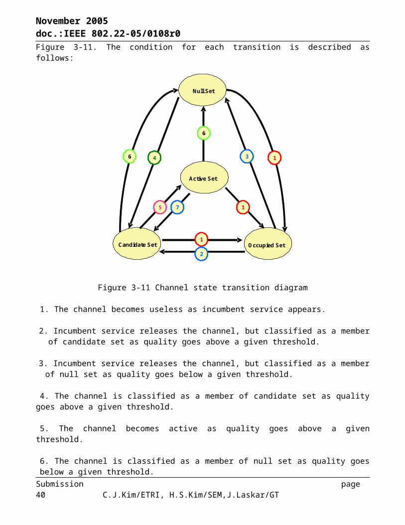
November 2005 doc.:IEEE 802.22-05/0108r0
Scanning result }
Channel ID
Scanning method refers to the channel measurement types, e.g., CIR.Scanning method
for (i=1; Number of channels_to_scan) {
Management message type = xxx
Note
Number of channels for which CPE performs scanningNumber of channels_to_scan
Field
Scanning result }
Channel ID
Scanning method refers to the channel measurement types, e.g., CIR.Scanning method
for (i=1; Number of channels_to_scan) {
Management message type = xxx
Note
Number of channels for which CPE performs scanningNumber of channels_to_scan
Field
3.9 Radio Resource Management
Radio resource management (RRM) function must ensure to maximize the bandwidth utilization. The proposed system provides some means of channel switching when a CPE find a channel with better quality, which can maximize the average system throughput. In other word, it is important to determine the channel that warrants a quality, as the system throughput is directly determined by the channel quality. Toward that end, we need to address the procedures of selecting the active set 1 for individual CPE in the downlink and uplink (“Channel matching” procedure) and selecting a group of CPE’s assigned to the same channel (“Channel grouping” procedure). Channel matching and channel grouping procedures must be performed so as to maximize the system utilization (average throughput) while minimizing the system cost with the constraints on guard band for FDD operation, co-channel interference, cross-talk in transceiver, etc.
3.9.1 Channel Grouping and Matching
The channel grouping is defined as a procedure of selecting a group of CPE’s that are sharing the same channels. It is valid only for multi-channel system. Local-area switching is performed by channel grouping. It is different from the channel switching in the course of channel management, which is performed only when a channel quality goes below incumbent detection threshold with appearance of incumbent users. In case that the channel quality degrades while still operating above incumbent detection threshold, channel grouping is performed so as to switch the channel for some CPE’s, which intends to maximize the overall average system throughput. In other words, some dynamic means of switching the channel per CPE is required for channel grouping. The channel conditions for all channels in the active, candidate, and occupied sets, that are monitored
during the quiet period, are reported to BS. In case that a channel with better quality is found in active set 2 than one in the current active set 1, some of CPE’s or all CPE’s in the same group move to the new channel band as long as BS can support it. Then BS transmits “leave” and “join” command via DL_Frame_Prefix in both channels. The above MSC specifies the corresponding procedure for channel switching in the course of channel grouping. Figure 3-16 illustrates how a channel is matched and grouped for CPE’s.Table 3-14 details the implicit channel grouping procedure.
Submission page 40 C.J.Kim/ETRI, H.S.Kim/SEM,J.Laskar/GT

November 2005 doc.:IEEE 802.22-05/0108r0
CH Matching
1
4
4
1’
4’
4’
CH Matching:To select (UL and DL) active set 1 for
individual CPE
CH Grouping:To select a group of
CPE’s that are assigned to the same
channel
CPE
CPE
CPE
CH Matching
BS
1 2 3 N 1’ 2’ N’3’
DL UL
Figure 3-16 Channel matching and grouping
Submission page 41 C.J.Kim/ETRI, H.S.Kim/SEM,J.Laskar/GT

November 2005 doc.:IEEE 802.22-05/0108r0
Table 3-14 Channel grouping procedure
Search for DCD and UCD in the active set 1DCD, UCDTransmit the UCD & DCD in a new channel
Perform a ranging process before initiating normal communication in the new channel.
Perform a ranging process before initiating normal communication in the new channel. Ranging
response
Transmit change notification to the CPE’s using DL_MAP Prefix. Update the active set 1 for each CPE.
Rangingcode
DL_MAP prefix
1. Perform scanning.2. Report the scan results.
Scan response
If a CPE reports a more preferable channel in the active set 2 than the current one, BS updates the active set 1 of the corresponding CPE.
Scan request
Transmit Scan request message to provide a scan period for individual CPE.
CPE operationCPEBSBS operation
Submission page 42 C.J.Kim/ETRI, H.S.Kim/SEM,J.Laskar/GT

November 2005 doc.:IEEE 802.22-05/0108r0
References:
[1] IEEE Standard for Local and Metropolitan Area Network-Part 16: Air Interface for Fixed Broadband Wireless Access Systems, IEEE Std. 802.16-2004
[2] Digital Video Broadcasting(DVB); Framing Structure, Channel Coding and Modulation for Digital Terrestrial Television, ETSI EN 300 744 V1.5.1(2004-06)
[3] Transmission System for Digital Terrestrial Television Broadcasting, ARIB STD-B31 V1.5[4] IEEE Standard for Local and Metropolitan Area Networks-Part 11: Wireless LAN Medium Access
Control(MAC) and Physical Layer(PHY) Specifications, IEEE Std 802.11a-1999[5] IEEE Std 802.11h-2003 (Amendment to IEEE Std 802.11, 1999 Edn. (Reaff 2003)) Publication Date: 2003
Abbreviations
AAS Analog Auto-CorrelationBE Best EffortBR Bandwidth RequestBS Base StationCC Convolutional CodeCID Connection IDentifierCoS Class of ServiceCPE Consumer Premise EquipmentCQI Channel Quality IndicatorCR Cognitive RadioCRC Cyclic Redundancy CheckCTC Convolutional Turbo CodeDCD Downlink Channel DescriptorDFS Dynamic Frequency SelectionDL DownlinkDSA Dynamic Service AdditionEC Encryption ControlFA Frequency AllocationFCH Frame Control HeaderFDD Frequency Division DuplexingHT Header TypeIE Information ElementIU Incumbent UserLDPC Low Density Perity CheckMAC Medium Access ControlMRSS Multi-Resolution Spectrum SensingnrtPS non real time Polling ServiceOFDMA Orthogonal Frequency Division Multiple AccessPDU Protocol Data UnitPHSI Packet Header Suppression IndicatorPHY PHYsical layerPU Primary UserQoS Quality of ServiceRRM Radio Resource ManagementRTG Receive/Transmit Transition GaprtPS real time Polling ServiceSDU Service Data UnitTDD Time Division Duplexing
Submission page 43 C.J.Kim/ETRI, H.S.Kim/SEM,J.Laskar/GT
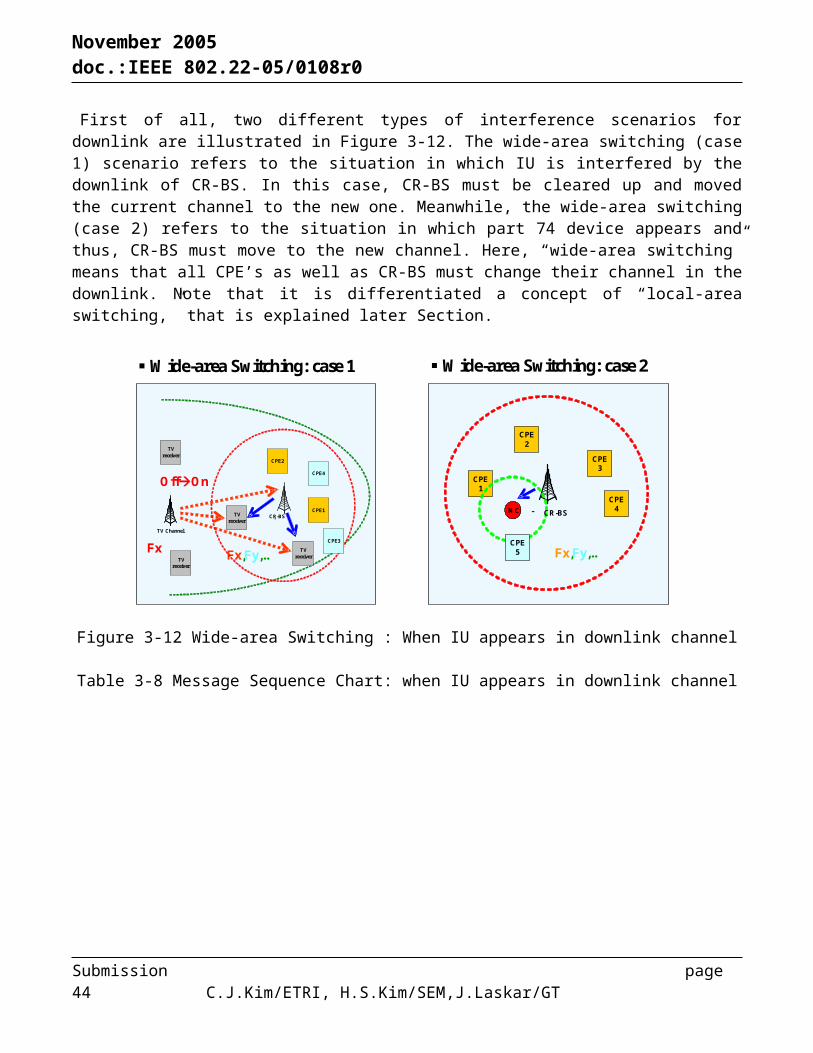
November 2005 doc.:IEEE 802.22-05/0108r0
TTG Transmit/Receive Transition GapUCD Uplink Channel DescriptorUGS Unsolicited Grant ServiceUL UplinkWRAN Wireless Regional Area Network
Submission page 44 C.J.Kim/ETRI, H.S.Kim/SEM,J.Laskar/GT