docs-emea.rs- 2009 schneider electric 18-1 all rights reserved 18 iec contactors and starters table...
TRANSCRIPT
18-1© 2009 Schneider ElectricAll Rights Reserved
18IE
C C
ON
TA
CT
OR
S A
ND
S
TA
RT
ER
S
Table of Contents
Section 18TeSys® IEC Contactors and Starters
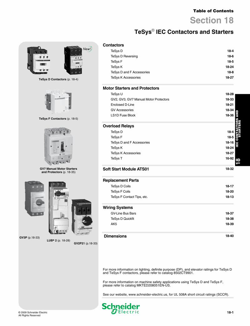
TeSys D Contactors (p. 18-4)
TeSys F Contactors (p. 18-5)
GV7 Manual Motor Starters and Protectors (p. 18-35)
GV3P (p.18-33)LUB•2 (p. 18-28)
GV2P21 (p.18-33)
New!Contactors
TeSys D 18-4
TeSys D Reversing 18-6
TeSys F 18-5
TeSys K 18-24
TeSys D and F Accessories 18-8
TeSys K Accessories 18-27
Motor Starters and ProtectorsTeSys U 18-28
GV2, GV3, GV7 Manual Motor Protectors 18-33
Enclosed D-Line 18-21
GV Accessories 18-34
LS1D Fuse Block 18-36
Overload RelaysTeSys D 18-4
TeSys F 18-5
TeSys D and F Accessories 18-16
TeSys K 18-24
TeSys K Accessories 18-27
TeSys T 16-92
Soft Start Module ATS01 18-32
Replacement PartsTeSys D Coils 18-17
TeSys F Coils 18-20
TeSys F Contact Tips, etc. 18-13
Wiring SystemsGV-Line Bus Bars 18-37
TeSys D Quickfit 18-38
AK5 18-39
Dimensions 18-40
For more information on lighting, definite purpose (DP), and elevator ratings for TeSys D and TeSys F contactors, please refer to catalog 8502CT9901.
For more information on machine safety applications using TeSys D and TeSys F, please refer to catalog MKTED208051EN-US.
See our website, www.schneider-electric.us, for UL 508A short circuit ratings (SCCR).
www.schneider-electric.us
18IE
C C
ON
TA
CT
OR
S A
ND
S
TA
RT
ER
S
18-2 © 2009 Schneider ElectricAll Rights Reserved
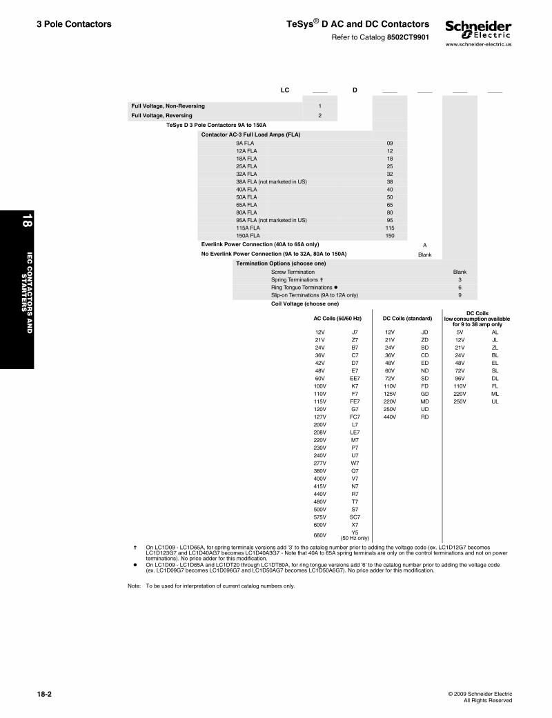
3 Pole Contactors TeSys® D AC and DC ContactorsRefer to Catalog 8502CT9901
s On LC1D09 - LC1D65A, for spring terminals versions add '3' to the catalog number prior to adding the voltage code (ex. LC1D12G7 becomes LC1D123G7 and LC1D40AG7 becomes LC1D40A3G7 - Note that 40A to 65A spring terminals are only on the control terminations and not on power terminations). No price adder for this modification.
t On LC1D09 - LC1D65A and LC1DT20 through LC1DT80A, for ring tongue versions add '6' to the catalog number prior to adding the voltage code (ex. LC1D09G7 becomes LC1D096G7 and LC1D50AG7 becomes LC1D50A6G7). No price adder for this modification.
Note: To be used for interpretation of current catalog numbers only.
LC _____ D _____ _____ _____ _____
Full Voltage, Non-Reversing 1
Full Voltage, Reversing 2
TeSys D 3 Pole Contactors 9A to 150A
Contactor AC-3 Full Load Amps (FLA)
9A FLA 0912A FLA 1218A FLA 1825A FLA 2532A FLA 3238A FLA (not marketed in US) 3840A FLA 4050A FLA 5065A FLA 6580A FLA 8095A FLA (not marketed in US) 95115A FLA 115150A FLA 150
Everlink Power Connection (40A to 65A only) A
No Everlink Power Connection (9A to 32A, 80A to 150A) Blank
Termination Options (choose one)
Screw Termination BlankSpring Terminations s 3Ring Tongue Terminations t 6Slip-on Terminations (9A to 12A only) 9
Coil Voltage (choose one)
AC Coils (50/60 Hz) DC Coils (standard)DC Coils
low consumption available for 9 to 38 amp only
12V J7 12V JD 5V AL21V Z7 21V ZD 12V JL24V B7 24V BD 21V ZL36V C7 36V CD 24V BL42V D7 48V ED 48V EL48V E7 60V ND 72V SL60V EE7 72V SD 96V DL100V K7 110V FD 110V FL110V F7 125V GD 220V ML115V FE7 220V MD 250V UL120V G7 250V UD127V FC7 440V RD200V L7208V LE7220V M7230V P7240V U7277V W7380V Q7400V V7415V N7440V R7480V T7500V S7575V SC7600V X7
660V Y5 (50 Hz only)
www.schneider-electric.us
18IE
C C
ON
TA
CT
OR
S A
ND
S
TA
RT
ER
S
© 2009 Schneider ElectricAll Rights Reserved
18-3
2, 3, and 4 Pole Contactors
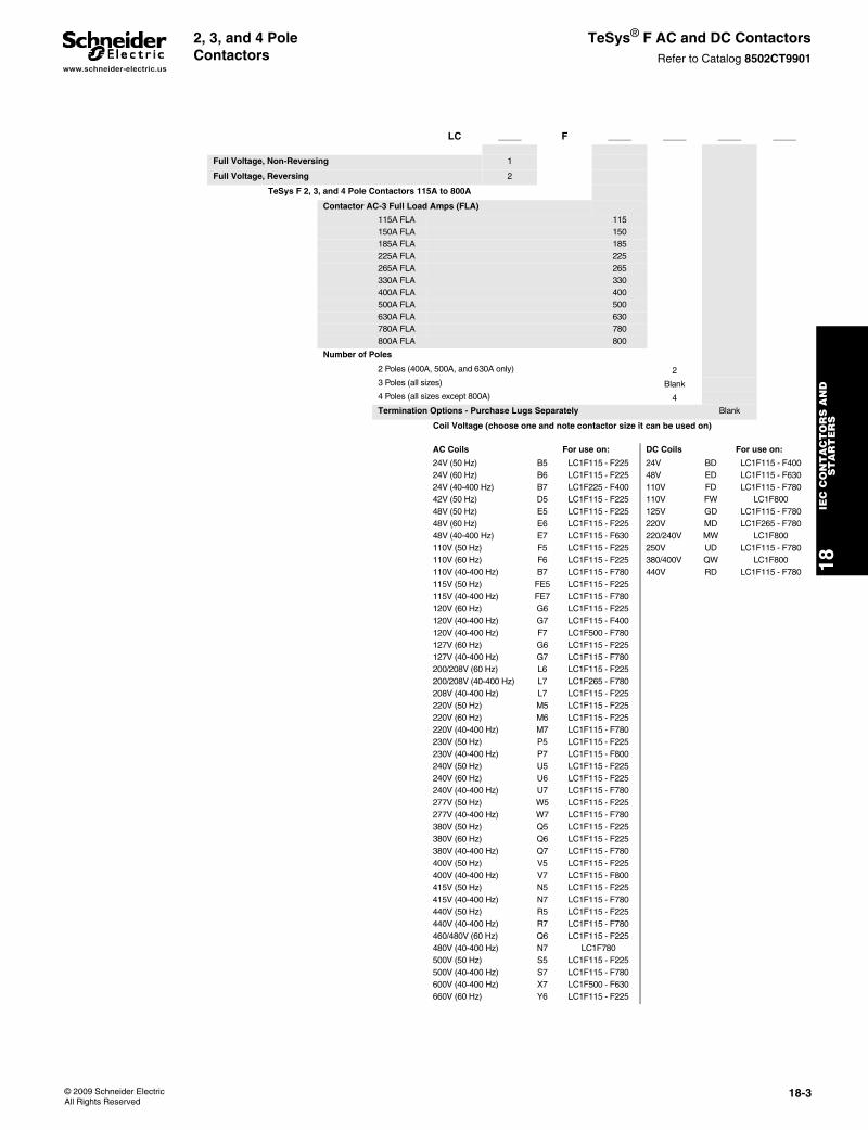
TeSys® F AC and DC ContactorsRefer to Catalog 8502CT9901
LC _____ F _____ _____ _____ _____
Full Voltage, Non-Reversing 1
Full Voltage, Reversing 2
TeSys F 2, 3, and 4 Pole Contactors 115A to 800A
Contactor AC-3 Full Load Amps (FLA)
115A FLA 115150A FLA 150185A FLA 185225A FLA 225265A FLA 265330A FLA 330400A FLA 400500A FLA 500630A FLA 630780A FLA 780800A FLA 800
Number of Poles
2 Poles (400A, 500A, and 630A only) 23 Poles (all sizes) Blank4 Poles (all sizes except 800A) 4
Termination Options - Purchase Lugs Separately Blank
Coil Voltage (choose one and note contactor size it can be used on)
AC Coils For use on: DC Coils For use on:
24V (50 Hz) B5 LC1F115 - F225 24V BD LC1F115 - F40024V (60 Hz) B6 LC1F115 - F225 48V ED LC1F115 - F63024V (40-400 Hz) B7 LC1F225 - F400 110V FD LC1F115 - F78042V (50 Hz) D5 LC1F115 - F225 110V FW LC1F80048V (50 Hz) E5 LC1F115 - F225 125V GD LC1F115 - F78048V (60 Hz) E6 LC1F115 - F225 220V MD LC1F265 - F78048V (40-400 Hz) E7 LC1F115 - F630 220/240V MW LC1F800110V (50 Hz) F5 LC1F115 - F225 250V UD LC1F115 - F780110V (60 Hz) F6 LC1F115 - F225 380/400V QW LC1F800110V (40-400 Hz) B7 LC1F115 - F780 440V RD LC1F115 - F780115V (50 Hz) FE5 LC1F115 - F225115V (40-400 Hz) FE7 LC1F115 - F780120V (60 Hz) G6 LC1F115 - F225120V (40-400 Hz) G7 LC1F115 - F400120V (40-400 Hz) F7 LC1F500 - F780127V (60 Hz) G6 LC1F115 - F225127V (40-400 Hz) G7 LC1F115 - F780200/208V (60 Hz) L6 LC1F115 - F225200/208V (40-400 Hz) L7 LC1F265 - F780208V (40-400 Hz) L7 LC1F115 - F225220V (50 Hz) M5 LC1F115 - F225220V (60 Hz) M6 LC1F115 - F225220V (40-400 Hz) M7 LC1F115 - F780230V (50 Hz) P5 LC1F115 - F225230V (40-400 Hz) P7 LC1F115 - F800240V (50 Hz) U5 LC1F115 - F225240V (60 Hz) U6 LC1F115 - F225240V (40-400 Hz) U7 LC1F115 - F780277V (50 Hz) W5 LC1F115 - F225277V (40-400 Hz) W7 LC1F115 - F780380V (50 Hz) Q5 LC1F115 - F225380V (60 Hz) Q6 LC1F115 - F225380V (40-400 Hz) Q7 LC1F115 - F780400V (50 Hz) V5 LC1F115 - F225400V (40-400 Hz) V7 LC1F115 - F800415V (50 Hz) N5 LC1F115 - F225415V (40-400 Hz) N7 LC1F115 - F780440V (50 Hz) R5 LC1F115 - F225440V (40-400 Hz) R7 LC1F115 - F780460/480V (60 Hz) Q6 LC1F115 - F225480V (40-400 Hz) N7 LC1F780500V (50 Hz) S5 LC1F115 - F225500V (40-400 Hz) S7 LC1F115 - F780600V (40-400 Hz) X7 LC1F500 - F630660V (60 Hz) Y6 LC1F115 - F225
www.schneider-electric.us
18IE
C C
ON
TA
CT
OR
S A
ND
S
TA
RT
ER
S
18-4 © 2009 Schneider ElectricAll Rights Reserved
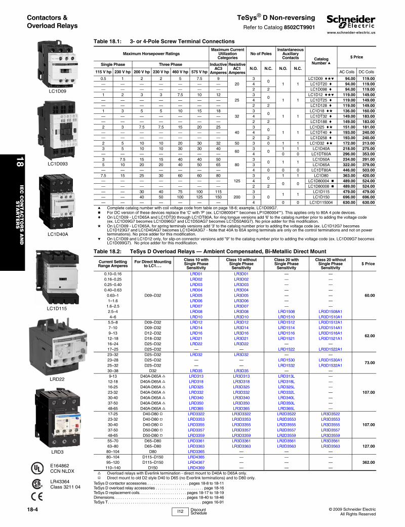
Contactors & Overload Relays
TeSys® D Non-reversingRefer to Catalog 8502CT9901
TeSys D contactor accessories . . . . . . . . . . . . . . . . . . . . pages 18-8 to 18-11TeSys D overload relay accessories . . . . . . . . . . . . . . . . . . . . . . . page 18-16TeSys D replacement coils. . . . . . . . . . . . . . . . . . . . . . . pages 18-17 to 18-19Dimensions. . . . . . . . . . . . . . . . . . . . . . . . . . . . . . . . . . . pages 18-40 to 18-46TeSys T. . . . . . . . . . . . . . . . . . . . . . . . . . . . . . . . . . . . . . . . . . . . . pages 16-91
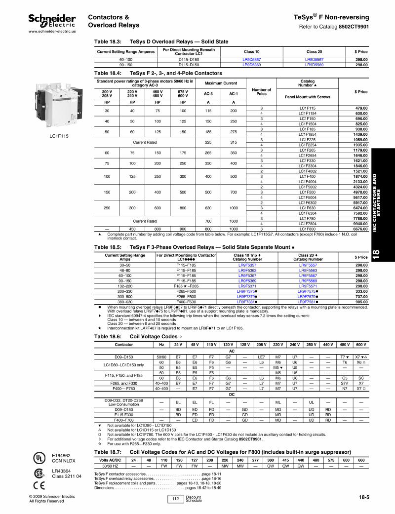
LC1D09
LC1D40A
LC1D093
LC1D115
LRD22
LRD3
E164862CCN NLDX
LR43364Class 3211 04
Table 18.1: 3- or 4-Pole Screw Terminal Connections
Maximum Horsepower RatingsMaximum Current
Utilization Categories
No of PolesInstantaneous
AuxiliaryContacts Catalog
Number a
$ Price
Single Phase Three Phase InductiveAC3
Amperes
ResistiveAC1
AmperesN.O. N.C. N.O. N.C.
115 V hp 230 V hp 200 V hp 230 V hp 460 V hp 575 V hp AC Coils DC Coils
0.5 1 2 2 5 7.5 920
30
1 1LC1D09 cde 94.00 119.00
— — — — — — — 4 LC1DT20 c 94.00 119.00— — — — — — — 2 2 LC1D098 c 94.00 119.001 2 3 3 7.5 10 12
253
01 1
LC1D12 cde 119.00 149.00— — — — — — — 4 LC1DT25 c 119.00 149.00— — — — — — — 2 2 LC1D128 c 119.00 149.001 3 5 5 10 15 18
323
01 1
LC1D18 cd 136.00 160.00— — — — — — — 4 LC1DT32 c 149.00 183.00— — — — — — — 2 2 LC1D188 c 149.00 183.002 3 7.5 7.5 15 20 25
403
01 1
LC1D25 cd 151.00 181.00— — — — — — — 4 LC1DT40 c 193.00 240.00— — — — — — — 2 2 LC1D258 c 193.00 240.002 5 10 10 20 30 32 50 3 0 1 1 LC1D32 cd 172.00 213.003 5 10 10 30 30 40
603
01 1 LC1D40A 218.00 275.00
— — — — — — — 4 0 0 LC1DT60A 296.00 353.003 7.5 15 15 40 40 50
803
0 1 1LC1D50A 234.00 291.00
5 10 20 20 40 50 65 3 LC1D65A 322.00 379.00— — — — — — — 4 0 0 0 LC1DT80A 446.00 503.007.5 15 25 30 60 60 80
1253
01 1 LC1D80 363.00 420.00
— — — — — — — 40 0
LC1D80004 b 489.00 524.00— — — — — — — 2 2 LC1D80008 b 489.00 524.00— — 30 40 75 100 115
2003
01 1
LC1D115 479.00 479.00— — 40 50 100 125 150 3 LC1D150 696.00 696.00— — — — — — — 4 0 0 LC1D115004 630.00 630.00
a Complete catalog number with coil voltage code from table on page 18-6; example, LC1D09G7. b For DC version of these devices replace the 'C' with 'P' (ex. LC1D80004** becomes LP1D80004**). This applies only to 80A 4 pole devices.c On LC1D09 - LC1D65A and LC1DT20 through LC1DT80A, for ring tongue versions add '6' to the catalog number prior to adding the voltage code
(ex. LC1D09G7 becomes LC1D096G7 and LC1D50AG7 becomes LC1D50A6G7). No price adder for this modification.d On LC1D09 - LC1D65A, for spring terminals versions add '3' to the catalog number prior to adding the voltage code (ex. LC1D12G7 becomes
LC1D123G7 and LC1D40AG7 becomes LC1D40A3G7 - Note that 40A to 65A spring terminals are only on the control terminations and not on power terminations). No price adder for this modification.
e On LC1D09 and LC1D12 only, for slip-on connector versions add "9" to the catalog number prior to adding the voltage code (ex. LC1D09G7 becomes LC1D099G7). No price adder for this modification.
Table 18.2: TeSys D Overload Relays — Ambient Compensated, Bi-Metallic Direct Mount
Current Setting Range Amperes
For Direct Mountingto LC1...
Class 10 with Single Phase
Sensitivity
Class 10 without Single Phase
Sensitivity
Class 20 with Single Phase
Sensitivity
Class 20 without Single Phase
Sensitivity$ Price
0.10–0.16
D09–D32
LRD01 LR3D01 — —
60.00
0.16–0.25 LRD02 LR3D02 — —0.25–0.40 LRD03 LR3D03 — —0.40–0.63 LRD04 LR3D04 — —
0.63–1 LRD05 LR3D05 — —1–1.6 LRD06 LR3D06 — —
1.6–2.5 LRD07 LR3D07 — —2.5–4 LRD08 LR3D08 LRD1508 LR3D1508A14–6 LRD10 LR3D10 LRD1510 LR3D1510A1
5.5–8 D09–D32 LRD12 LR3D12 LRD1512 LR3D1512A1
62.00
7–10 D09–D32 LRD14 LR3D14 LRD1514 LR3D1514A19–13 D12–D32 LRD16 LR3D16 LRD1516 LR3D1516A112–18 D18–D32 LRD21 LR3D21 LRD1521 LR3D1521A116–24 D25–D32 LRD22 LR3D22 — —17–25 D25–D32 — — LRD1522 LR3D1522A123–32 D25–D32 LRD32 LR3D32 — —
73.0023–28 D25–D32 — — LRD1530 LR3D1530A125–32 D25–D32 — — LRD1532 LR3D1532A130–38 D32 LRD35 LR3D35 — —9-13 D40A-D65A f LRD313 LR3D313 LRD313L —
107.00
12-18 D40A-D65A f LRD318 LR3D318 LRD318L —16-25 D40A-D65A f LRD325 LR3D325 LRD325L —23-32 D40A-D65A f LRD332 LR3D332 LRD332L —30-40 D40A-D65A f LRD340 LR3D340 LRD340L —37-50 D40A-D65A f LRD350 LR3D350 LRD350L —48-65 D40A-D65A f LRD365 LR3D365 LRD365L —17-25 D40-D80 g LRD3322 LR3D3322 LR2D3522 LR3D3522
107.0023-32 D40-D80 g LRD3353 LR3D3353 LR2D3553 LR3D355330-40 D40-D80 g LRD3355 LR3D3355 LR2D3555 LR3D355537-50 D50-D80 g LRD3357 LR3D3357 LR2D3557 LR3D355748-65 D50-D80 g LRD3359 LR3D3359 LR2D3559 LR3D355955–70 D65–D80 LRD3361 LR3D3361 LR2D3561 LR3D3561
127.0063–80 D65–D80 LRD3363 LR3D3363 LR2D3563 LR3D356380–104 D80 LRD3365 — — —80–104 D115–D150 LRD4365 — — —
362.0095–120 D115–D150 LRD4367 — — —110–140 D150 LRD4369 — — —
f Overload relays with Everlink termination - direct mount to D40A to D65A only.g Direct mount to old D2 style D40 to D65 (no Everlink terminations) and to D80 only.
I12 Discount Schedule
www.schneider-electric.us
18IE
C C
ON
TA
CT
OR
S A
ND
S
TA
RT
ER
S
© 2009 Schneider ElectricAll Rights Reserved
18-5
Contactors & Overload Relays
TeSys® F Non-reversingRefer to Catalog 8502CT9901
a Complete part number by adding coil voltage code from table below. For example: LC1F115G7. All contactors (except F780) include 1 N.O. coil interlock contact.
TeSys F contactor accessories. . . . . . . . . . . . . . . . . . . . . . . . . . . .page 18-11TeSys F overload relay accessories . . . . . . . . . . . . . . . . . . . . . . . .page 18-16TeSys F replacement coils and parts . . . . . . . . . . pages 18-13, 18-18, 18-20Dimensions . . . . . . . . . . . . . . . . . . . . . . . . . . . . . . . . . . pages 18-42 to 18-49
LC1F115
E164862CCN NLDX
LR43364Class 3211 04
Table 18.3: TeSys D Overload Relays — Solid State
Current Setting Range Amperes For Direct Mounting Beneath Contractor LC1 Class 10 Class 20 $ Price
60–100 D115–D150 LR9D5367 LR9D5567 298.0090–150 D115–D150 LR9D5369 LR9D5569 298.00
Table 18.4: TeSys F 2-, 3-, and 4-Pole ContactorsStandard power ratings of 3-phase motors 50/60 Hz in
category AC-3 Maximum Current
Number of Poles
Catalog Number a
$ Price200 V208 V
220 V240 V
460 V480 V
575 V600 V AC-3 AC-1
Panel Mount with Screws HP HP HP HP A A
30 40 75 100 115 2003 LC1F115 479.004 LC1F1154 630.00
40 50 100 125 150 2503 LC1F150 696.004 LC1F1504 825.00
50 60 125 150 185 2753 LC1F185 938.004 LC1F1854 1439.00
Current Rated 225 3153 LC1F225 1059.004 LC1F2254 1935.00
60 75 150 175 265 3503 LC1F265 1179.004 LC1F2654 1646.00
75 100 200 250 330 4003 LC1F330 1621.004 LC1F3304 1846.00
100 125 250 300 400 5002 LC1F4002 1521.003 LC1F400 1874.004 LC1F4004 2133.00
150 200 400 500 500 7002 LC1F5002 4324.003 LC1F500 4970.004 LC1F5004 5617.00
250 300 600 800 630 10002 LC1F6302 5917.003 LC1F630 6474.004 LC1F6304 7582.00
Current Rated 780 16003 LC1F780 7788.004 LC1F7804 9940.00
— 450 800 900 800 1000 3 LC1F800 6676.00
Table 18.5: TeSys F 3-Phase Overload Relays — Solid State Separate Mount bCurrent Setting Range
AmpsFor Direct Mounting to Contactor
LC1●●●●
Class 10 Trip cCatalog Number
Class 20 cCatalog Number $ Price
30–50 F115–F185 LR9F5357 LR9F5557 298.0048–80 F115–F185 LR9F5363 LR9F5563 298.0060–100 F115–F185 LR9F5367 LR9F5567 298.0090–150 F115–F185 LR9F5369 LR9F5569 298.00132–220 F185 d –F265 LR9F5371 LR9F5571 298.00200–330 F265–F500 LR9F7375b LR9F7575b 333.00300–500 F265–F500 LR9F7379b LR9F7579b 737.00380–630 F400–F630 LR9F7381b LR9F7581b 905.00
b When mounting overload relays LR9F5●57 to LR9F5●71 directly beneath the contactor, supporting the relays with a mounting plate is recommended. With overload relays LR9F7●75 to LR9F7●81, use of a support mounting plate is mandatory.
c IEC standard 60947-4 specifies the following trip times when the overload relay senses 7.2 times the setting current:Class 10 — between 4 and 10 secondsClass 20 — between 6 and 20 seconds
d Interconnection kit LA7F407 is required to mount an LR9F●71 to an LC1F185.
Table 18.6: Coil Voltage Codes hContactor Hz 24 V 48 V 110 V 120 V 125 V 208 V 220 V 240 V 250 V 440 V 480 V 600 V
AC
D09–D150 50/60 B7 E7 F7 G7 — LE7 M7 U7 — — T7 e X7 ef
LC1D80–LC1D150 only60 B6 E6 F6 G6 — L6 M6 U6 — — T6 X6 f50 B5 E5 F5 — — — M5 e U5 — — — —
F115, F150, and F18550 B5 E5 F5 — — — M5 U5 — — — —60 B6 E6 F6 G6 — L6 M6 U6 — — Q5 SC
F265, and F330 40–400 B7 E7 F7 G7 — L7 M7 U7 — — S7i X7F400— F780 40–400 — E7 F7 G7 — L7 M7 U7 — — N7 X7 g
DC
D09-D32, DT20-D258 Low Consumption — BL EL FL — — — ML — UL — — —
D09–D150 — BD ED FD — GD — MD — UD RD — —F115-F330 — BD ED FD — GD — MD — UD RD — —F400–F780 — — ED FD — GD — MD — UD RD — —
e Not available for LC1D80 - LC1D150f Not available for LC1D115 or LC1D150g Not available for LC1F780. The 600 V coils for the LC1F400 - LC1F630 do not include an auxiliary contact for holding circuits.h For additional voltage codes refer to the IEC Contactor and Starter Catalog 8502CT9901.i For use with F265—F330 only.
Table 18.7: Coil Voltage Codes for AC and DC Voltages for F800 (includes built-in surge suppressor)Volts AC/DC 24 48 110 120 127 208 220 240 277 380 415 440 480 575 600 660
50/60 HZ — — FW FW FW — MW MW — QW QW QW — — — —
I12 Discount Schedule
www.schneider-electric.us
18IE
C C
ON
TA
CT
OR
S A
ND
S
TA
RT
ER
S
18-6 © 2009 Schneider ElectricAll Rights Reserved
Contactors TeSys® D 3- and 4-Pole Reversing, AC or DC Operating CoilRefer to Catalog 8502CT9901
Each 3-pole device is pre-wired with line and load side power wiring for reversing applications.Each 4-pole device is pre-wired with load side power wiring
TeSys D contactor accessories . . . . . . . . . . . . . . . . . . . . pages 18-8 to 18-11TeSys D overload relay accessories . . . . . . . . . . . . . . . . . . . . . . . page 18-16TeSys D replacement coils. . . . . . . . . . . . . . . . . . . . . . . pages 18-17 to 18-19Dimensions. . . . . . . . . . . . . . . . . . . . . . . . . . . . . . . . . . . pages 18-40 to 18-46
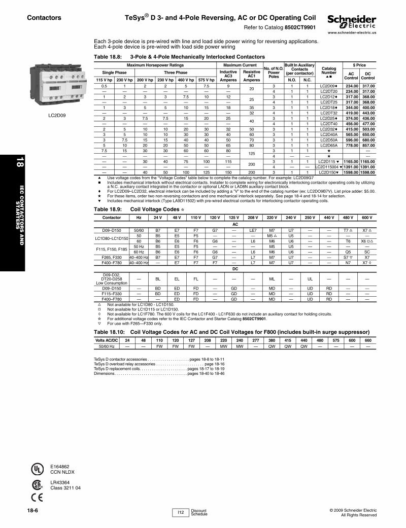
LC2D09
E164862CCN NLDX
LR43364Class 3211 04
Table 18.8: 3-Pole & 4-Pole Mechanically Interlocked ContactorsMaximum Horsepower Ratings Maximum Current
No. of N.O. Power Poles
Built In Auxiliary Contacts
(per contactor)Catalog Numberab
$ Price
Single Phase Three Phase Inductive AC3
Amperes
Resistive AC1
Amperes
AC Control
DC Control115 V hp 230 V hp 200 V hp 230 V hp 460 V hp 575 V hp N.O. N.C.
0.5 1 2 2 5 7.5 920
3 1 1 LC2D09c 234.00 317.00— — — — — — — 4 1 1 LC2DT20 234.00 317.001 2 3 3 7.5 10 12
253 1 1 LC2D12c 317.00 368.00
— — — — — — — 4 1 1 LC2DT25 317.00 368.001 3 5 5 10 15 18 35 3 1 1 LC2D18c 344.00 400.00— — — — — — — 32 4 1 1 LC2DT32 419.00 443.002 3 7.5 7.5 15 20 25
403 1 1 LC2D25c 374.00 436.00
— — — — — — — 4 1 1 LC2DT40 456.00 477.002 5 10 10 20 30 32 50 3 1 1 LC2D32c 415.00 503.003 5 10 10 30 30 40 60 3 1 1 LC2D40A 565.00 650.003 7.5 15 15 40 40 50 70 3 1 1 LC2D50A 596.00 680.005 10 20 20 50 50 65 80 3 1 1 LC2D65A 778.00 857.00
7.5 15 30 30 60 60 80125
3 1 1 d — — — — — — — — 4 — — d — — — 30 40 75 100 115
2003 1 1 LC2D115 e 1165.00 1165.00
— — — — — — — 4 — — LC2D115004 e 1391.00 1391.00— — 40 50 100 125 150 200 3 1 1 LC2D150e 1598.00 1598.00
a Use voltage codes from the “Voltage Codes” table below to complete the catalog number. For example: LC2D09G7b Includes mechanical interlock without electrical contacts. Installer to complete wiring for electronically interlocking contactor operating coils by utilizing
a N.C. auxiliary contact integrated in the contactor or optional LADN or LAD8N auxiliary contact block.c For LC2D09–LC2D32, electrical interlock can be included by adding a ”V” to the end of the catalog number (ex: LC2DO9B7V). List price adder: $5.00.d For these items, order two non-reversing contactors and one mechanical interlock separately. See page 18-4 and 18-14 for selection.e Includes mechanical interlock (Type LA9D11502) with pre-wired electrical contacts for interlocking contactor operating coils.
Table 18.9: Coil Voltage Codes iContactor Hz 24 V 48 V 110 V 120 V 125 V 208 V 220 V 240 V 250 V 440 V 480 V 600 V
AC
D09–D150 50/60 B7 E7 F7 G7 — LE7 M7 U7 — — T7 f X7 f
LC1D80–LC1D15050 B5 E5 F5 — — — M5 f U5 — — — —60 B6 E6 F6 G6 — L6 M6 U6 — — T6 X6 gf
F115, F150, F18550 Hz B5 E5 F5 — — — M5 U5 — — — —60 Hz B6 E6 F6 G6 — L6 M6 U6 — — Q5 SC
F265, F330 40–400 Hz B7 E7 F7 G7 — L7 M7 U7 — — S7 j X7F400–F780 40–400 Hz — E7 F7 F7 — L7 M7 U7 — — N7 X7 h
DC
D09-D32, DT20-D258
Low Consumption— BL EL FL — — — ML — UL — — —
D09–D150 — BD ED FD — GD — MD — UD RD — —F115–F330 — BD ED FD — GD — MD — UD RD — —F400–F780 — — ED FD — GD — MD — UD RD — —
f Not available for LC1D80 - LC1D150.g Not available for LC1D115 or LC1D150.h Not available for LC1F780. The 600 V coils for the LC1F400 - LC1F630 do not include an auxiliary contact for holding circuits.i For additional voltage codes refer to the IEC Contactor and Starter Catalog 8502CT9901. j For use with F265—F330 only.
Table 18.10: Coil Voltage Codes for AC and DC Coil Voltages for F800 (includes built-in surge suppressor)Volts AC/DC 24 48 110 120 127 208 220 240 277 380 415 440 480 575 600 660
50/60 Hz — — FW FW FW — MW MW — QW QW QW — — — —
I12 Discount Schedule
www.schneider-electric.us
18IE
C C
ON
TA
CT
OR
S A
ND
S
TA
RT
ER
S
© 2009 Schneider ElectricAll Rights Reserved
18-7
Contactors TeSys® F 3-Pole Reversing, AC or DC Operating CoilRefer to Catalog 8502CT9901
HOW TO ORDER:Components are available for customer assembly of TeSys F reversing contactors. For example, the following components must be ordered to build a 75 hp @ 460 V reversing contactor with a 120 V/60 Hz coil:
TeSys F contactor accessories. . . . . . . . . . . . . . . . . . . . . . . . . . . .page 18-11TeSys F overload relay accessories. . . . . . . . . . . . . . . . . . . . . . . .page 18-16TeSys F replacement coils and parts . . . . . . . . . . pages 18-13, 18-18, 18-20Dimensions . . . . . . . . . . . . . . . . . . . . . . . . . . . . . . . . . . . . . . . . . . .page 18-42
Table 18.11: Quantity Catalog Number Description
2 LC1F115G6 Contactors6 DZ2FF1 Lugs (page 18-12)2 LADN11 Auxiliary contacts1 LA9FF976 Power connections1 LA9FF970 Mechanical interlock
Table 18.12: 3-Pole ContactorsMaximum Horsepower Ratings Maximum Current Holding Circuit
Contact BuiltInto Coil Catalog
Numbera $ PriceThree Phase InductiveAC3
Amperes
ResistiveAC1
Amperes200 Vhp
230 Vhp
460 Vhp
575 Vhp N.O. N.C.
30 40 75 100 115 200 1 0 LC1F115 479.0040 50 100 125 150 250 1 0 LC1F150 696.0050 60 125 150 185 275 1 0 LC1F185 938.0060 75 150 200 265 350 1 0 LC1F265 1179.0075 100 200 250 330 400 1 0 LC1F330 1621.00
100 125 250 300 400 500 1 0 LC1F400 1874.00150 200 400 500 500 700 1 0 LC1F500 4970.00250 300 600 800 630 1000 1 0 LC1F630 6872.00
Current rated 780 1600 0 0 LC1F780 7788.00— 450 800 900 800 1000 0 0 LC1F800 6676.00
a Use coil voltage codes from the “Voltage Codes” table on page 18-6 to complete the contactor catalog number.
Table 18.13: Auxiliary contact (electrical interlocking) - 2 must be purchased
For use with Number of Contacts
Maximum Number of Blocks
Per ContactorContact Arrangement Catalog Number $ Price
LC1Fto be ordered
separately
1 11 — LADN10 13.10— 1 LADN01 13.10
2 21 1 LADN11 20.702 - LADN20 20.70
4 2
2 2 LADN22 41.501 3 LADN13 41.504 — LADN40 41.50— 4 LADN04 41.503 1 LADN31 41.502 2 b LADC22 41.50
b including 1 N.O. + 1 N.C. make-before-break
Table 18.14: Accessories—For the assembly of three-pole reversing contactors (horizontal mounting)
With 2 IdenticalContactors c
Set Of Power ConnectionsCatalog Number $ Price
Horizontal MountingMechanical Interlock Kit
Catalog Number$ Price
LC1F115 LA9FF976 106.00 LA9FF970 53.00LC1F150 LA9F15076 96.00 LA9FF970 53.00LC1F185 LA9FG976 113.00 LA9FG970 53.00LC1F265 LA9FH976 151.00 LA9FJ970 76.00LC1F330 LA9FJ976 225.00 LA9FJ970 76.00LC1F400 LA9FJ976 198.00 LA9FJ970 76.00LC1F500 LA9FK976 306.00 LA9FJ970 76.00
LC1F630, F800 LA9FL976 568.00 LA9FL970 76.00c For two contactors of different size, refer to pages 18-15.
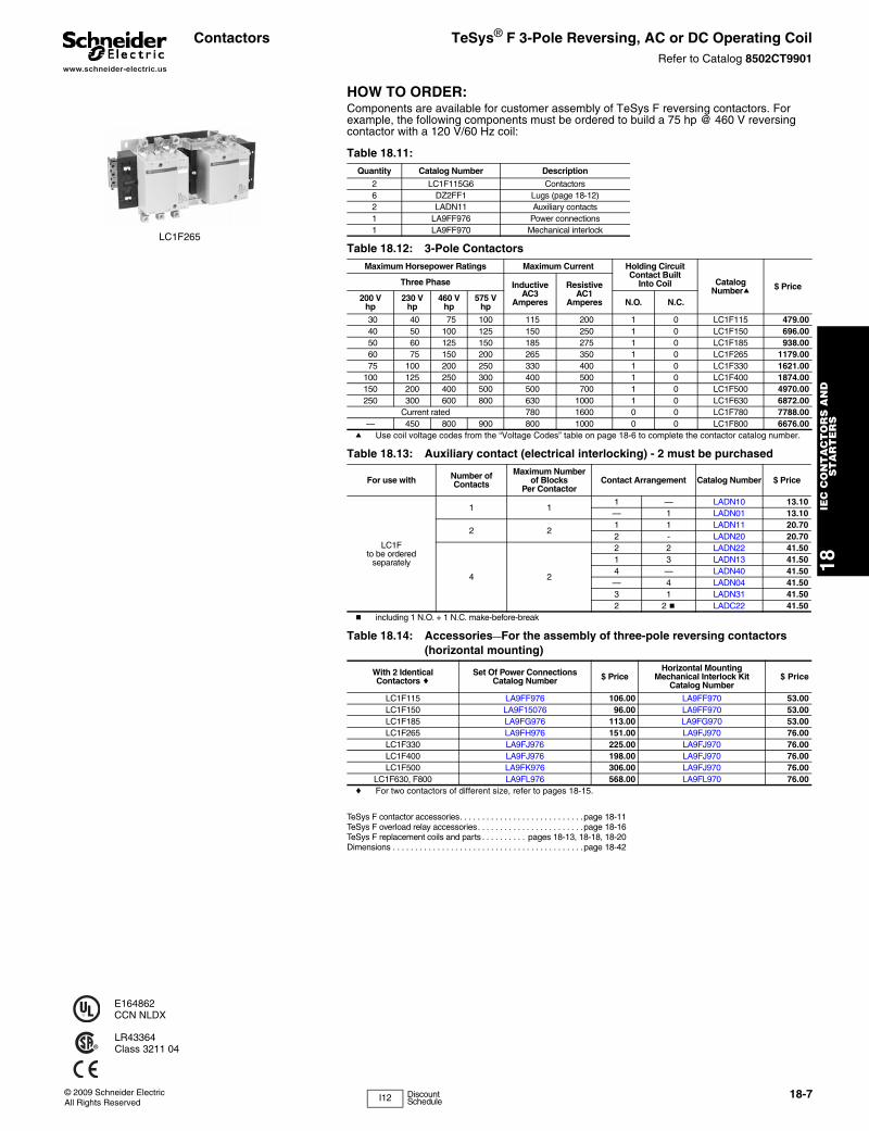
LC1F265
E164862CCN NLDX
LR43364Class 3211 04
I12 Discount Schedule
www.schneider-electric.us
18IE
C C
ON
TA
CT
OR
S A
ND
S
TA
RT
ER
S
18-8 © 2009 Schneider ElectricAll Rights Reserved
Contactor Accessories
TeSys® D & F Auxiliary Contacts, Time Delay, Mechanical LatchRefer to Catalog 8502CT9901
TeSys D contactors . . . . . . . . . . . . . . . . . . . . . . . . . . . . . . . .pages 18-4, 18-6TeSys D overload relay accessories . . . . . . . . . . . . . . . . . . . . . . . page 18-16TeSys D replacement coils . . . . . . . . . . . . . . . . . . . . . . pages 18-18 to 18-19Dimensions. . . . . . . . . . . . . . . . . . . . . . . . . . . . . . . . . . . pages 18-40 to 18-46
Table 18.15: Standard, instantaneous auxiliary contact blocks
Snap-OnMounting
Number ofContacts
CompositionCatalog Number a $ Price
N.O. N.C.
To front ofLC●DT20–D258 (4P),
LC●D09–D150aor
To right side ofLC●F
4 a
2 2 LADN22 b 41.501 3 LADN13 b 41.504 0 LADN40 b 41.500 4 LADN04 b 41.503 1 LADN31 b 41.50
2 c 2 c LADC22 bc 41.50
21 1 LADN11 b 20.702 0 LADN20 b 20.700 2 LADN02b 20.70
To front ofLC●D80 and D115
orTo left side of
LC●F
11 0 LADN10 d 13.100 1 LADN01 d 13.10
To side of LC●D09 to D150 only
(not for use on TeSys F)2 1 1 LAD8N11 e 20.70
2 0 LAD8N20 e 20.70a For low consumption coils (LC1D09 to D32 only), only one front-mounted two-contact block allowed. No side-
mounted contact blocks allowed.b For spring terminal versions of these blocks, add a “3” to the end of the catalog number. (Ex. LADN223). No price
adder for this modification.c Including 1 N.O. + 1 N.C. make before break overlapping contacts.d This block cannot be added to the LC1D 09 to D32 contactors; a maximum of 2 blocks can be mounted on the
LC1D40A to LC1/LP1D80 contactors only.e 1 block may be added to the left side of the LC1D 09 to D32, AC coils only; 1 block may be added to each side of
the LC1D 40A to D80 contactors, AC coils only. Cannot be installed on TeSys D contactors with DC coils.
Table 18.16: Instantaneous blocks with dust-tight auxiliary contacts (IP54) NEMA 12
Snap-OnMounting
Standard Contacts Dusttight ContactsCatalog Number $ Price
N.O. N.C. N.O. N.C.
To front ofLP●D40–D80, LC●DT20–D258 (4P),
LC●D09 to D80or
To right side ofLC●F
— — 2 — LA1DX20 65.002 — 2 — LA1DZ40 82.001 1 2 — LA1DZ31 82.00
— — 2 — LA1DY20f 77.00
f Device supplied with 4 ground terminal points.
Table 18.17: Pneumatic time delay contact blocks
Snap-On Mounting
Time DelayContacts Type Range of
Time DelayCatalog
Number h $ PriceN.O. N.C.
To front ofLP●D40–D80,
LC●DT20–D258 (4P), LC●D09 to D150
orTo right side of
LC●F
1 1 On energization(on delay)
0.1 to 3 sg LADT0 131.000.1 to 30 s LADT2 131.0010 to 180 s LADT4 131.001 to 30 si LADS2 131.00
1 1 On de-energization(off-delay)
0.1 to 3 sg LADR0 131.000.1 to 30 s LADR2 131.0010 to 180 s LADR4 131.00
g Scale range is expanded between 0.1 and 0.6 seconds on the dial for more accurate settings at the lower end of the range.
h For spring terminal versions of these blocks, add a “3” to the end of the catalog number. (Ex. LADT23). No price adder for this modification.
i With switching time of 40 ms ± 15 ms between the opening of the N.C. contact to the closing of the N.O. contact.
Table 18.18: Mechanical latch blocks with manual or electrical unlatch (TeSys D only)
Front snap-onmounting onto Application
Catalog numberto be completed
by the code correspondingto the coil voltage
$ Price
LC●D09 to D65A For silent operation and energy conservation LAD6K10jk 77.00
LC1 D80 to D150 LP1 D80 For silent operation and energyconservation LA6DK20jk 77.00
j Does not include internal coil clearing contact.k Complete catalog number by adding coil voltage code. For example: LAD6K10F.
Table 18.19: Coil Voltage Codes for LA6DK mechanical latch blocks
Volts 12 24 32/36 42/48 60/72 100 110/127
200/208
220/240
380/415
440/480
500/600
AC or DC J B C E EN K F L M Q R S
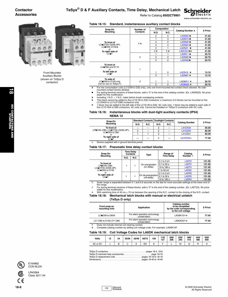
Front Mounted Auxiliary Blocks
(shown on TeSys D contactor)
E164862CCN NLDX
LR43364Class 3211 04
I12 Discount Schedule
www.schneider-electric.us
18IE
C C
ON
TA
CT
OR
S A
ND
S
TA
RT
ER
S
© 2009 Schneider ElectricAll Rights Reserved
18-9
Contactor Accessories TeSys® D Coil Suppressors, Cabling AccessoriesRefer to Catalog 8502CT9901
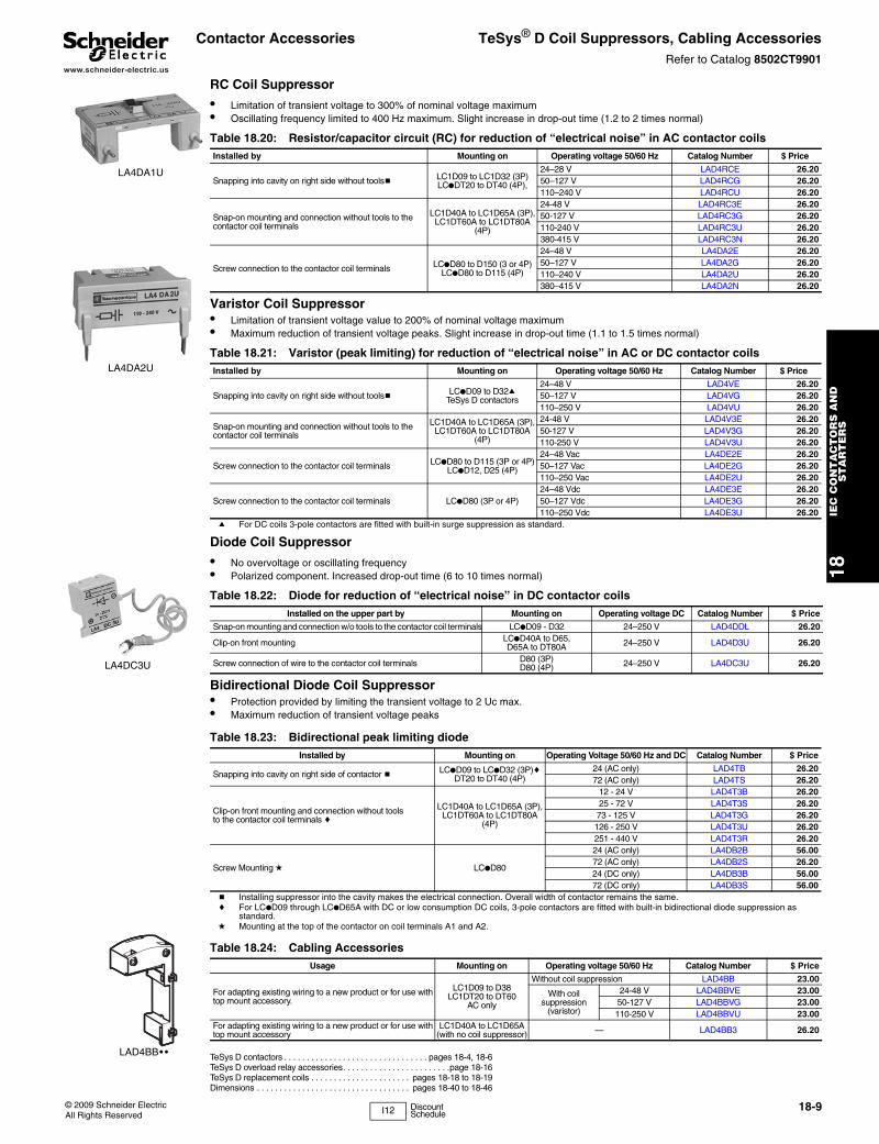
RC Coil Suppressor
• Limitation of transient voltage to 300% of nominal voltage maximum• Oscillating frequency limited to 400 Hz maximum. Slight increase in drop-out time (1.2 to 2 times normal)
Varistor Coil Suppressor• Limitation of transient voltage value to 200% of nominal voltage maximum• Maximum reduction of transient voltage peaks. Slight increase in drop-out time (1.1 to 1.5 times normal)
Diode Coil Suppressor
• No overvoltage or oscillating frequency• Polarized component. Increased drop-out time (6 to 10 times normal)
Bidirectional Diode Coil Suppressor• Protection provided by limiting the transient voltage to 2 Uc max.• Maximum reduction of transient voltage peaks
TeSys D contactors . . . . . . . . . . . . . . . . . . . . . . . . . . . . . . . . pages 18-4, 18-6TeSys D overload relay accessories. . . . . . . . . . . . . . . . . . . . . . . .page 18-16TeSys D replacement coils . . . . . . . . . . . . . . . . . . . . . . pages 18-18 to 18-19Dimensions . . . . . . . . . . . . . . . . . . . . . . . . . . . . . . . . . . pages 18-40 to 18-46
Table 18.20: Resistor/capacitor circuit (RC) for reduction of “electrical noise” in AC contactor coilsInstalled by Mounting on Operating voltage 50/60 Hz Catalog Number $ Price
Snapping into cavity on right side without toolsb LC1D09 to LC1D32 (3P)LC●DT20 to DT40 (4P),
24–28 V LAD4RCE 26.2050–127 V LAD4RCG 26.20110–240 V LAD4RCU 26.20
Snap-on mounting and connection without tools to the contactor coil terminals
LC1D40A to LC1D65A (3P), LC1DT60A to LC1DT80A
(4P)
24-48 V LAD4RC3E 26.2050-127 V LAD4RC3G 26.20110-240 V LAD4RC3U 26.20380-415 V LAD4RC3N 26.20
Screw connection to the contactor coil terminals LC●D80 to D150 (3 or 4P)LC●D80 to D115 (4P)
24–48 V LA4DA2E 26.2050–127 V LA4DA2G 26.20110–240 V LA4DA2U 26.20380–415 V LA4DA2N 26.20
Table 18.21: Varistor (peak limiting) for reduction of “electrical noise” in AC or DC contactor coilsInstalled by Mounting on Operating voltage 50/60 Hz Catalog Number $ Price
Snapping into cavity on right side without toolsb LC●D09 to D32aTeSys D contactors
24–48 V LAD4VE 26.2050–127 V LAD4VG 26.20110–250 V LAD4VU 26.20
Snap-on mounting and connection without tools to the contactor coil terminals
LC1D40A to LC1D65A (3P), LC1DT60A to LC1DT80A
(4P)
24-48 V LAD4V3E 26.2050-127 V LAD4V3G 26.20110-250 V LAD4V3U 26.20
Screw connection to the contactor coil terminals LC●D80 to D115 (3P or 4P)LC●D12, D25 (4P)
24–48 Vac LA4DE2E 26.2050–127 Vac LA4DE2G 26.20110–250 Vac LA4DE2U 26.20
Screw connection to the contactor coil terminals LC●D80 (3P or 4P)24–48 Vdc LA4DE3E 26.2050–127 Vdc LA4DE3G 26.20110–250 Vdc LA4DE3U 26.20
a For DC coils 3-pole contactors are fitted with built-in surge suppression as standard.
Table 18.22: Diode for reduction of “electrical noise” in DC contactor coilsInstalled on the upper part by Mounting on Operating voltage DC Catalog Number $ Price
Snap-on mounting and connection w/o tools to the contactor coil terminals LC●D09 - D32 24–250 V LAD4DDL 26.20
Clip-on front mounting LC●D40A to D65, D65A to DT80A 24–250 V LAD4D3U 26.20
Screw connection of wire to the contactor coil terminals D80 (3P)D80 (4P) 24–250 V LA4DC3U 26.20
Table 18.23: Bidirectional peak limiting diodeInstalled by Mounting on Operating Voltage 50/60 Hz and DC Catalog Number $ Price
Snapping into cavity on right side of contactor b LC●D09 to LC●D32 (3P)cDT20 to DT40 (4P)
24 (AC only) LAD4TB 26.2072 (AC only) LAD4TS 26.20
Clip-on front mounting and connection without tools to the contactor coil terminals c
LC1D40A to LC1D65A (3P), LC1DT60A to LC1DT80A
(4P)
12 - 24 V LAD4T3B 26.2025 - 72 V LAD4T3S 26.2073 - 125 V LAD4T3G 26.20126 - 250 V LAD4T3U 26.20251 - 440 V LAD4T3R 26.20
Screw Mounting d LC●D80
24 (AC only) LA4DB2B 56.0072 (AC only) LA4DB2S 26.2024 (DC only) LA4DB3B 56.0072 (DC only) LA4DB3S 56.00
b Installing suppressor into the cavity makes the electrical connection. Overall width of contactor remains the same.c For LC●D09 through LC●D65A with DC or low consumption DC coils, 3-pole contactors are fitted with built-in bidirectional diode suppression as
standard.d Mounting at the top of the contactor on coil terminals A1 and A2.
Table 18.24: Cabling AccessoriesUsage Mounting on Operating voltage 50/60 Hz Catalog Number $ Price
For adapting existing wiring to a new product or for use with top mount accessory.
LC1D09 to D38LC1DT20 to DT60
AC only
Without coil suppression LAD4BB 23.00
With coil suppression
(varistor)
24-48 V LAD4BBVE 23.0050-127 V LAD4BBVG 23.00110-250 V LAD4BBVU 23.00
For adapting existing wiring to a new product or for use with top mount accessory
LC1D40A to LC1D65A (with no coil suppressor) — LAD4BB3 26.20
LA4DA1U
LA4DA2U
LA4DC3U
LAD4BB• •
I12 Discount Schedule
www.schneider-electric.us
18IE
C C
ON
TA
CT
OR
S A
ND
S
TA
RT
ER
S
18-10 © 2009 Schneider ElectricAll Rights Reserved
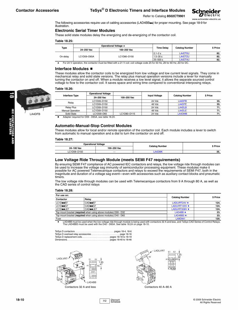
The following accessories require use of cabling accessories (LAD4BB●●) for proper mounting. See page 18-9 for illustration.
Electronic Serial Timer ModulesThese solid state modules delay the energizing and de-energizing of the contactor coil.
Interface Modules bThese modules allow the contactor coils to be energized from low voltage and low current level signals. They come in mechanical relay and solid state versions. The relay plus manual operation versions include a lever for manually turning the contactor on and off. When a module receives a low level signal, it allows the separate sourced control voltage to flow to the contactor coil. It saves space and wiring time compared to conventional interposing relays.
b Adapter required for D09 - D65A, see table 18.24.
Automatic-Manual-Stop Control ModulesThese modules allow for local and/or remote operation of the contactor coil. Each module includes a lever to switch from automatic to manual operation and a dial to turn the contactor on and off.
Low Voltage Ride Through Module (meets SEMI F47 requirements)By ensuring SEMI F47 compliance of AC powered IEC contactors and relays, the low voltage ride through modules can be used to increase the voltage sag immunity of semiconductor processing equipment. These modules make it possible for AC powered Telemecanique contactors and relays to exceed the requirements of SEMI F47, both in the magnitude and duration of a voltage sag event—even with accessories such as auxiliary contact blocks and pneumatic timers.The low voltage ride through modules can be used with Telemecanique contactors from 9 A through 80 A, as well as the CAD series of control relays
TeSys D contactors . . . . . . . . . . . . . . . . . . . . . . . . . . . . . . . .pages 18-4, 18-6TeSys D overload relay accessories . . . . . . . . . . . . . . . . . . . . . . . page 18-16TeSys D replacement coils. . . . . . . . . . . . . . . . . . . . . . . pages 18-18 to 18-19Dimensions. . . . . . . . . . . . . . . . . . . . . . . . . . . . . . . . . . . pages 18-40 to 18-46
Table 18.25:
TypeOperational Voltage a
Time Delay Catalog Number $ Price24–250 Vac 100–250 Vac
On-delay LC1D09–D65A LC1D80–D1500.1–2 s LA4DT0U 82.1.5–30 s LA4DT2U 82.25–500 s LA4DT4U 82.
a For 24 V operation, the contactor must be fitted with a 21 V coil: coil voltage code Z5 for 50 Hz; Z6 for 60 Hz; ZD for DC.
Table 18.26:
Interface TypeOperational Voltage
Input Voltage Catalog Number $ Price24–250 Vac 100–250 Vac
RelayLC1D09–D150 24 Vdc LA4DFB 55.LC1D09–D150 48 Vdc LA4DFE 55.
Relay Plus LC1D09–D150 24 Vdc LA4DLB 71.Manual Operation LC1D09–D150 48 Vdc LA4DLE 71.
Solid State LC1D09–D65 LC1D80–D115 24 Vdc LA4DWB 71.LA4DFB
Table 18.27: Operational Voltage
Catalog Number $ Price24–100 Vac 100–250 Vac
LC1D09–D150 — LA4DMK 35.
Table 18.28: For use on:
Catalog Number $ PriceContactor Relay
LC1D●●B7 CAD●●B7 LADLVRT24V c 124.LC1D●●G7 CAD●●G7 LADLVRT120V c 124.LC1D●●LE7 CAD●●LE7 LADLVRT208V c 124.Top mount bracket (required when using above modules) D09 - D32 LAD4BB c 23.Top mount bracket (required when using above modules) D40 - D65 LAD4BB3 c 23.Fuse LA9D941 120.c LAD4BB must be used when the low voltage ride through module is being used with contactors 32 A and less, and TeSys CAD Series of Control Relays.
The LAD4BB3 must be used with the D40 - D65A. See table 18.24 on page 18-10.
E2E1
A2A2
A1A1
1.2532
LADLVRT
1.8547
LAD4BB
E1 E2
A1 A2
LADLVRT
Contactors 40 A–80 AContactors 32 A and less
Contactor Accessories TeSys® D Electronic Timers and Interface ModulesRefer to Catalog 8502CT9901
I12 Discount Schedule
www.schneider-electric.us
18IE
C C
ON
TA
CT
OR
S A
ND
S
TA
RT
ER
S
© 2009 Schneider ElectricAll Rights Reserved
18-11
Contactor Accessories TeSys® D and F AccessoriesRefer to Catalog 8502CT9901
TeSys D contactors . . . . . . . . . . . . . . . . . . . . . . . . . . . . . . . . pages 18-4, 18-6TeSys D overload relay accessories. . . . . . . . . . . . . . . . . . . . . . . .page 18-16TeSys D replacement coils . . . . . . . . . . . . . . . . . . . . . . pages 18-18 to 18-19Dimensions . . . . . . . . . . . . . . . . . . . . . . . . . . . . . . . . . . pages 18-40 to 18-47TeSys F contactors . . . . . . . . . . . . . . . . . . . . . . . . . . . . . . . . pages 18-5, 18-7TeSys F replacement coils and parts . . . . . . . . . . pages 18-13, 18-18, 18-20
Table 18.29: For Power Pole or Control Connection
DescriptionFor use withcontactorsLC1/LP1
Sold in lots of
CatalogNumber $ Price each
Connectors for larger cable sizes
4 poles #8 AWG (10 mm2) D09, D12 1 LAD92560 8.703 poles #4 AWG (25 mm2) D09–D32 1 LA9D3260 12.00
Everlink® terminal block 3 poles D40A-D65A 1 LAD96560 10.00
Linksfor the parallel connection of
2 poles
D09–D32 10 LA9D2561 26.20D40A–D65A 1 LAD9P32 6.00
D80 2 LA9D80961 6.50F115 4 LA9FF602 55.00
F150, F185 4 LA9FG602 65.00F265, F330, F400 4 LA9FH602 169.00
F500 4 LA9FK602 228.00F630, F800 4 LA9FL602 278.00
3 poles(Wye-DeltaShorting Strap)
D09–D32 10 LAD9P3 10.00D40A-D65A 1 LAD9P33 25.00
D80 1 LA9D80962 6.50F115 1 LA9FF601 6.80
F150, F185 1 LA9FG601 8.20F265, F330, F400 1 LA9FH601 12.00
F500 1 LA9FK601 21.80F630, F800 1 LA9FL601 38.20
4 polesDT20, DT25 2 LA9D1263 8.70
D80 2 LA9D80963 17.50Second coil connection LP1D40–D80 10 LA9D09966 2.20
Control circuit take-off from main poleD115, D150 10 LA9D11567 4.00
D80 10 LA9D8067 5.50Spreaders for increasing pole pitch to 45 mm D115, D150 3 GV7AC03 31.10
Table 18.30: For Marking
DescriptionFor use withcontactorsLC1/LP1
Sold in lots of
CatalogNumber $ Price each
Reference label holder snap-on 8 x 22 mm 4-pole contactorsD80 - D115 100 LA9D92 .06
Reference label holder snap-on 8 x 18 mm 3 poles D09-D65A, DT20-DT80A, LADN, LADT, LADR 100 LAD90 .06
Sheet of 300 labels self adhesive 7 x 21 mm For holder LA9D92 1 LA9D93 4.30
Table 18.31: For Mounting
DescriptionFor use withcontactorsLC1/LP1
Sold in lots of
CatalogNumber $ Price each
Set of shims for mounting LAD8N and LA8DN D80 1 LA9D511 9.80Retrofit plate for replacement of LC1D40-D65 with LC1D40A-D65A D40A-D65A 1 LAD7X3 25.00
35 mm DIN Rail – 2 meters long LC1D09 to D80 10 AM1DP200 5.20
Table 18.32: Replacement contactsFor use withcontactors
CatalogNumber $ Price
Three-poleLC1D115 3 poles LA5D1158031 239.00LC1D150 3 poles LA5D150803 239.00
Four-pole LC1D115 4 poles LA5D115804 318.00
Table 18.33: Arc chambersFor use withcontactors
CatalogNumber $ Price
Three-poleLC1D115 3 poles LA5D11550 90.00LC1D150 3 poles LA5D15050 90.00
Four-pole LC1D115 4 poles LA5D115450 119.00
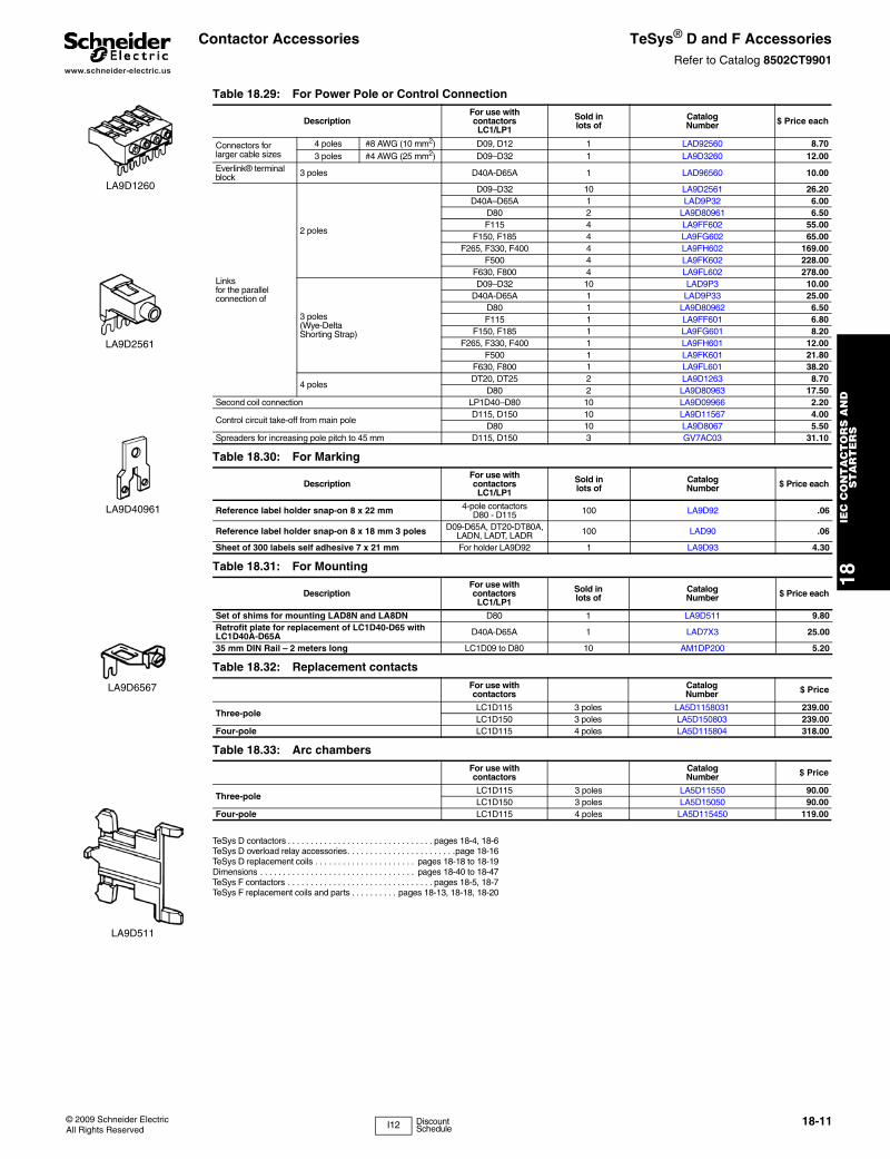
LA9D1260
LA9D2561
LA9D40961
LA9D6567
LA9D511
I12 Discount Schedule
www.schneider-electric.us
18IE
C C
ON
TA
CT
OR
S A
ND
S
TA
RT
ER
S
18-12 © 2009 Schneider ElectricAll Rights Reserved
Contactor Accessories TeSys® F ContactorsRefer to Catalog 8502CT9901
These clear plastic protective shrouds are an effective means to meet international touch-safe requirements for power terminals. They are designed to be used with power cables that have been bolted to the terminal.NOTE: The protection shrouds do not attach to contactors or overloads utilizing DZ2F lug kits.
For contactors LC1F115, LC1F150, and LC1F185, an available touch-safe terminal block may be used in place of lugs for power connections.
TeSys F contactors . . . . . . . . . . . . . . . . . . . . . . . . . . . . . . . .pages 18-5, 18-7TeSys F overload relay accessories . . . . . . . . . . . . . . . . . . . . . . . page 18-16TeSys F replacement coils and parts . . . . . . . . . .pages 18-18, 18-18, 18-20Dimensions. . . . . . . . . . . . . . . . . . . . . . . . . . . . . . . . . . . pages 18-40 to 18-47
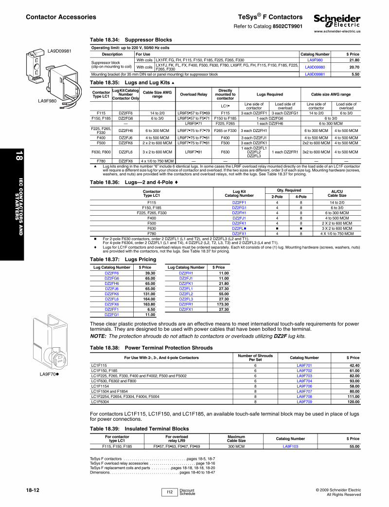
LA9D09981
LA9F980
Table 18.34: Suppressor BlocksOperating limit: up to 220 V, 50/60 Hz coils
Description For Use Catalog Number $ Price
Suppressor block (clip-on mounting to coil)
With coils LX1FF, FG, FH, F115, F150, F185, F225, F265, F330 LA9F980 21.80
With coils LX1FJ, FK, FL, FX, F400, F500, F630, F780, LX9FF, FG, FH, F115, F150, F185, F225, F265, F330 LA9D09980 20.70
Mounting bracket (for 35 mm DIN rail or panel mounting) for suppressor block LA9D09981 5.50
Table 18.35: Lugs and Lug Kits a
ContactorType LC1
Lug Kit Catalog Number
Contactor Only
Cable Size AWG range Overload Relay
Directly mounted to contactor
Lugs Required Cable size AWG range
LC1• Line side of contactor
Load side of overload
Line side of contactor
Load side of overload
F115 DZ2FF6 14 to 2/0 LR9F5•57 to F5•69 F115 3 each DZ2FF1 3 each DZ2FG1 14 to 2/0 6 to 3/0F150, F185 DZ2FG6 6 to 3/0 LR9F5•57 to F5•71 F150 to F185 1 each DZ2FG6 6 to 3/0
— LR9F5•71 F225, F265 1 each DZ2FH6 6 to 300 MCMF225, F265,
F330 DZ2FH6 6 to 300 MCM LR9F7•75 to F7•79 F265 or F330 3 each DZ2FH1 6 to 300 MCM 4 to 500 MCM
F400 DZ2FJ6 4 to 500 MCM LR9F7•75 to F7•81 F400 3 each DZ2FJ1 4 to 500 MCM 4 to 500 MCMF500 DZ2FK6 2 x 2 to 600 MCM LR9F7•75 to F7•81 F500 3 each DZ2FK1 2x2 to 600 MCM 4 to 500 MCM
F630, F800 DZ2FL6 3 x 2 to 600 MCM LR9F7•81 F6301 each DZ2FL1
DZ2FL2DZ2FL3
1 each DZ2FR1 3x2 to 600 MCM 4 to 500 MCM
F780 DZ2FX6 4 x 1/0 to 750 MCM — — — —a Lug kits ending in the number “6” include 6 identical lugs. In some cases the LR9F overload relay mounted directly on the load side of an LC1F contactor
will require a different size lug for your choice of contactor and overload. If the two sizes are different, order 3 of each size lug. Mounting hardware (screws, washers, and nuts) are provided with the contactors and overload relays, not with the lugs. See Table 18.37 for pricing.
Table 18.36: Lugs—2 and 4-Pole c
Contactor Type LC1
Lug KitCatalog Number
Qty. Required AL/CUCable Size2-Pole 4-Pole
F115 DZ2FF1 4 8 14 to 2/0F150, F185 DZ2FG1 4 8 6 to 3/0
F225, F265, F330 DZ2FH1 4 8 6 to 300 MCMF400 DZ2FJ1 4 8 4 to 500 MCMF500 DZ2FK1 4 8 2 X 2 to 600 MCMF630 DZ2FLb b b 3 X 2 to 600 MCM F780 DZ2FX1 4 8 4 X 1/0 to 750 MCM
b For 2-pole F630 contactors, order 2 DZ2FL1 (L1 and T2), and 2 DZ2FL3 (L2 and T1). For 4-pole F6304, order 2 DZ2FL1 (L1 and T4), 4 DZ2FL2 (L2, T2, L3, T3) and 2 DZ2FL3 (L4 and T1).
c Lugs for LC1F contactors and overload relays must be ordered separately. Each kit consists of one (1) lug. Mounting hardware (screws, washers, nuts) are provided with the contactors, not the lugs. See Table 18.37 for pricing.
Table 18.37: Lugs PricingLug Catalog Number $ Price Lug Catalog Number $ Price
DZ2FF6 39.30 DZ2FH1 11.00DZ2FG6 65.00 DZ2FJ1 11.00DZ2FH6 65.00 DZ2FK1 21.80DZ2FJ6 65.00 DZ2FL1 27.30DZ2FK6 131.00 DZ2FL2 55.00DZ2FL6 164.00 DZ2FL3 27.30DZ2FX6 163.80 DZ2FR1 173.30DZ2FF1 6.50 DZ2FX1 27.30DZ2FG1 11.00
LA9F70
Table 18.38: Power Terminal Protection Shrouds
For Use With 2-, 3-, And 4-pole Contactors Number of ShroudsPer Set Catalog Number $ Price
LC1F115 6 LA9F701 42.40LC1F150, F185 6 LA9F702 61.00LC1F225, F265, F330, F400 and F4002, F500 and F5002 6 LA9F703 82.00LC1F630, F6302 and F800 6 LA9F704 93.00LC1F1154 8 LA9F706 58.00LC1F1504 and F1854 8 LA9F707 80.00LC1F2254, F2654, F3304, F4004, F5004 8 LA9F708 111.00LC1F6304 8 LA9F709 120.00
Table 18.39: Insulated Terminal BlocksFor contactor
type LC1For overload
relay LR9MaximumCable Size Catalog Number $ Price
F115, F150, F185 F5•57, F5•63, F5•67, F5•69 300 MCM LA9F103 55.00
I12 Discount Schedule
www.schneider-electric.us
18IE
C C
ON
TA
CT
OR
S A
ND
S
TA
RT
ER
S
© 2009 Schneider ElectricAll Rights Reserved
18-13
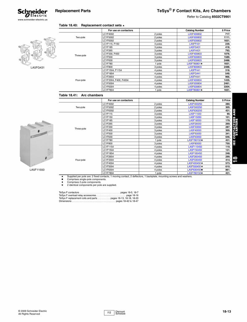
Replacement Parts TeSys® F Contact Kits, Arc ChambersRefer to Catalog 8502CT9901
TeSys F contactors . . . . . . . . . . . . . . . . . . . . . . . . . . . . . . . . pages 18-5, 18-7TeSys F overload relay accessories . . . . . . . . . . . . . . . . . . . . . . . .page 18-16TeSys F replacement coils and parts . . . . . . . . . . pages 18-13, 18-18, 18-20Dimensions . . . . . . . . . . . . . . . . . . . . . . . . . . . . . . . . . . pages 18-42 to 18-47
LA5FG431
LA5F11550
Table 18.40: Replacement contact sets aFor use on contactors Catalog Number $ Price
Two-poleLC1F4002 2 poles LA5F400802 717.LC1F5002 2 poles LA5F500802 1111.LC1F6302 2 poles LA5F630802 1651.
Three-pole
LC1F115, F150 3 poles LA5FF431 239.LC1F185 3 poles LA5FG431 418.LC1F265 3 poles LA5FH431 793.LC1F330, F400 3 poles LA5F400803 1076.LC1F500 3 poles LA5F500803 1589.LC1F630 3 poles LA5F630803 2488.LC1F780 1 pole LA5F780801d 1651.LC1F800 3 poles LA5F800803 2488.
Four-pole
LC1F1504, F1154 4 poles LA5FF441 318.LC1F1854 4 poles LA5FG441 549.LC1F2654 4 poles LA5FH441 966.LC1F3304, F400, F4004 4 poles LA5F400804 1435.LC1F5004 4 poles LA5F500804 2461.LC1F6304 4 poles LA5F630804 3304.LC1F7804 1 pole LA5F780801d 1651.
Table 18.41: Arc chambersFor use on contactors Catalog Number $ Price
Two-poleLC1F4002 2 poles LA5F400250 280.LC1F5002 2 poles LA5F500250 305.LC1F6302 2 poles LA5F630250 431.
Three-pole
LC1F115 3 poles LA5F11550 90.LC1F150 3 poles LA5F15050 101.LC1F185 3 poles LA5F18550 179.LC1F265 3 poles LA5F26550 269.LC1F330 3 poles LA5F33050 287.LC1F400 3 poles LA5F40050 305.LC1F500 3 poles LA5F50050 341.LC1F630 3 poles LA5F63050 646.LC1F780 1 pole LA5F780150d 431.LC1F800 3 poles LA5F80050 750.
Four-pole
LC1F1154 4 poles LA5F115450 119.LC1F1504 4 poles LA5F150450 131.LC1F1854 4 poles LA5F185450 248.LC1F2654 4 poles LA5F265450 299.LC1F3304 4 poles LA5F330450 414.LC1F4004 4 poles LA5F400450c 573.LC1F5004 4 poles LA5F500450c 610.LC1F6304 4 poles LA5F630450b 861.LC1F7804 1 pole LA5F780150d 431.
a Supplied per pole are: 2 fixed contacts, 1 moving contact, 2 deflectors, 1 backplate, mounting screws and washers.b Comprises single-pole components.c Comprises 2-pole components.d 2 identical components per pole are supplied.
I12 Discount Schedule
www.schneider-electric.us
18IE
C C
ON
TA
CT
OR
S A
ND
S
TA
RT
ER
S
18-14 © 2009 Schneider ElectricAll Rights Reserved
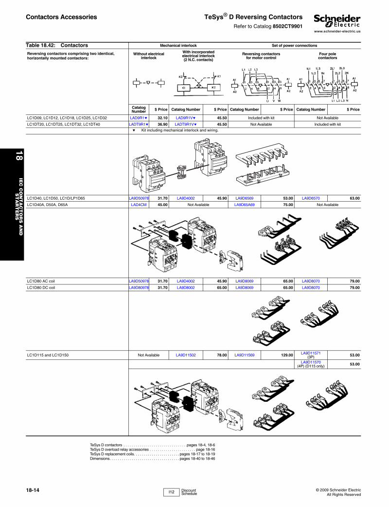
Contactors Accessories TeSys® D Reversing ContactorsRefer to Catalog 8502CT9901
TeSys D contactors . . . . . . . . . . . . . . . . . . . . . . . . . . . . . . . .pages 18-4, 18-6TeSys D overload relay accessories . . . . . . . . . . . . . . . . . . . . . . . page 18-16TeSys D replacement coils. . . . . . . . . . . . . . . . . . . . . . . pages 18-17 to 18-19Dimensions. . . . . . . . . . . . . . . . . . . . . . . . . . . . . . . . . . . pages 18-40 to 18-46
Table 18.42: Contactors Mechanical interlock Set of power connections
Reversing contactors comprising two identical, horizontally mounted contactors:
Without electricalinterlock
With incorporatedelectrical interlock(2 N.C. contacts)
Reversing contactorsfor motor control
Four polecontactors
Catalog Number $ Price Catalog Number $ Price Catalog Number $ Price Catalog Number $ Price
LC1D09, LC1D12, LC1D18, LC1D25, LC1D32 LAD9R1e 32.10 LAD9R1Ve 45.50 Included with kit Not Available
LC1DT20, LC1DT25, LC1DT32, LC1DT40 LADT9R1e 36.90 LADT9R1Ve 45.50 Not Available Included with kit
e Kit including mechanical interlock and wiring.
LC1D40, LC1D50, LC1D/LP1D65 LA9D50978 31.70 LA9D4002 45.90 LA9D6569 53.00 LA9D6570 63.00
LC1D40A, D50A, D65A LAD4CM 45.00 Not Available LA9D65A69 75.00 Not Available
LC1D80 AC coil LA9D50978 31.70 LA9D4002 45.90 LA9D8069 65.00 LA9D8070 79.00
LC1D80 DC coil LA9D80978 31.70 LA9D8002 65.00 LA9D8069 65.00 LA9D8070 79.00
LC1D115 and LC1D150 Not Available LA9D11502 78.00 LA9D11569 129.00 LA9D11571(3P) 53.00
LA9D11570(4P) (D115 only) 53.00
I12 Discount Schedule
www.schneider-electric.us
18IE
C C
ON
TA
CT
OR
S A
ND
S
TA
RT
ER
S
© 2009 Schneider ElectricAll Rights Reserved
18-15
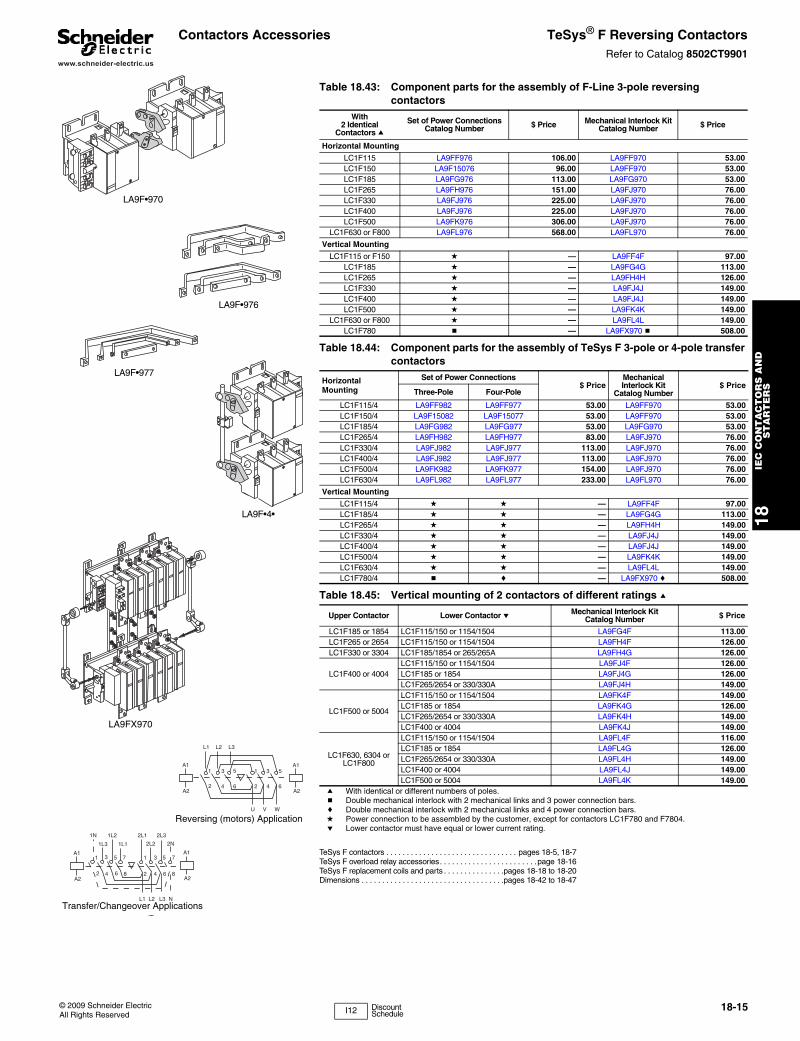
Contactors Accessories TeSys® F Reversing ContactorsRefer to Catalog 8502CT9901
TeSys F contactors . . . . . . . . . . . . . . . . . . . . . . . . . . . . . . . . pages 18-5, 18-7TeSys F overload relay accessories. . . . . . . . . . . . . . . . . . . . . . . .page 18-16TeSys F replacement coils and parts . . . . . . . . . . . . . . .pages 18-18 to 18-20Dimensions . . . . . . . . . . . . . . . . . . . . . . . . . . . . . . . . . . .pages 18-42 to 18-47
Table 18.43: Component parts for the assembly of F-Line 3-pole reversing contactors
With2 Identical
Contactors a
Set of Power ConnectionsCatalog Number $ Price Mechanical Interlock Kit
Catalog Number $ Price
Horizontal Mounting
LC1F115 LA9FF976 106.00 LA9FF970 53.00LC1F150 LA9F15076 96.00 LA9FF970 53.00LC1F185 LA9FG976 113.00 LA9FG970 53.00LC1F265 LA9FH976 151.00 LA9FJ970 76.00LC1F330 LA9FJ976 225.00 LA9FJ970 76.00LC1F400 LA9FJ976 225.00 LA9FJ970 76.00LC1F500 LA9FK976 306.00 LA9FJ970 76.00
LC1F630 or F800 LA9FL976 568.00 LA9FL970 76.00
Vertical Mounting
LC1F115 or F150 d — LA9FF4F 97.00LC1F185 d — LA9FG4G 113.00LC1F265 d — LA9FH4H 126.00LC1F330 d — LA9FJ4J 149.00LC1F400 d — LA9FJ4J 149.00LC1F500 d — LA9FK4K 149.00
LC1F630 or F800 d — LA9FL4L 149.00LC1F780 b — LA9FX970 b 508.00
Table 18.44: Component parts for the assembly of TeSys F 3-pole or 4-pole transfer contactors
Horizontal Mounting
Set of Power Connections$ Price
Mechanical Interlock Kit
Catalog Number$ Price
Three-Pole Four-Pole
LC1F115/4 LA9FF982 LA9FF977 53.00 LA9FF970 53.00LC1F150/4 LA9F15082 LA9F15077 53.00 LA9FF970 53.00LC1F185/4 LA9FG982 LA9FG977 53.00 LA9FG970 53.00LC1F265/4 LA9FH982 LA9FH977 83.00 LA9FJ970 76.00LC1F330/4 LA9FJ982 LA9FJ977 113.00 LA9FJ970 76.00LC1F400/4 LA9FJ982 LA9FJ977 113.00 LA9FJ970 76.00LC1F500/4 LA9FK982 LA9FK977 154.00 LA9FJ970 76.00LC1F630/4 LA9FL982 LA9FL977 233.00 LA9FL970 76.00
Vertical Mounting
LC1F115/4 d d — LA9FF4F 97.00LC1F185/4 d d — LA9FG4G 113.00LC1F265/4 d d — LA9FH4H 149.00LC1F330/4 d d — LA9FJ4J 149.00LC1F400/4 d d — LA9FJ4J 149.00LC1F500/4 d d — LA9FK4K 149.00LC1F630/4 d d — LA9FL4L 149.00LC1F780/4 b c — LA9FX970 c 508.00
Table 18.45: Vertical mounting of 2 contactors of different ratings a
Upper Contactor Lower Contactor e Mechanical Interlock Kit Catalog Number $ Price
LC1F185 or 1854 LC1F115/150 or 1154/1504 LA9FG4F 113.00LC1F265 or 2654 LC1F115/150 or 1154/1504 LA9FH4F 126.00LC1F330 or 3304 LC1F185/1854 or 265/265A LA9FH4G 126.00
LC1F400 or 4004LC1F115/150 or 1154/1504 LA9FJ4F 126.00LC1F185 or 1854 LA9FJ4G 126.00LC1F265/2654 or 330/330A LA9FJ4H 149.00
LC1F500 or 5004
LC1F115/150 or 1154/1504 LA9FK4F 149.00LC1F185 or 1854 LA9FK4G 126.00LC1F265/2654 or 330/330A LA9FK4H 149.00LC1F400 or 4004 LA9FK4J 149.00
LC1F630, 6304 orLC1F800
LC1F115/150 or 1154/1504 LA9FL4F 116.00LC1F185 or 1854 LA9FL4G 126.00LC1F265/2654 or 330/330A LA9FL4H 149.00LC1F400 or 4004 LA9FL4J 149.00LC1F500 or 5004 LA9FL4K 149.00
a With identical or different numbers of poles.b Double mechanical interlock with 2 mechanical links and 3 power connection bars.c Double mechanical interlock with 2 mechanical links and 4 power connection bars.d Power connection to be assembled by the customer, except for contactors LC1F780 and F7804.e Lower contactor must have equal or lower current rating.
LA9F•970
LA9F•976
LA9F•977
LA9F•4•
LA9FX970
L1 L2 L3
A1
A2
A1
A2
1 3 5 1 3 5
2 4 6 2 4 6
U V W
Reversing (motors) Application
A1
A2
A1
A2
1N 1L2 2L1 2L3
1L3 1L1 2L2 2N
1 3 5 7 1 3 5 7
2 4 6 8 2 4 6 8
L1 L2 L3 N
Transfer/Changeover Applications
I12 Discount Schedule
www.schneider-electric.us
18IE
C C
ON
TA
CT
OR
S A
ND
S
TA
RT
ER
S
18-16 © 2009 Schneider ElectricAll Rights Reserved
Overload Relays TeSys® D and F Overload Relay AccessoriesRefer to Catalog 8502CT9901
TeSys D Overload Relay Accessories
TeSys F Overload Relay Accessories
These clear plastic protective shrouds are an effective means to meet international finger-safe requirements for power terminals. They are designed to be used with power cables that have been bolted to the terminal. NOTE: The protection shrouds do not attach to contactors or overloads utilizing DZ2F lug kits.
Main overload selection . . . . . . . . . . . . . . . . . . . . . . . . . . . . .pages 18-2, 18-3Dimensions. . . . . . . . . . . . . . . . . . . . . . . . . . . . . . . . . . . pages 18-45 to 18-47TeSys T. . . . . . . . . . . . . . . . . . . . . . . . . . . . . . . . . . . . . . . . . . . . . pages 16-91
Table 18.46: Mounting Kits and PlatesaDescription For use with overload relays: Catalog Number $ Price
Separate mounting kits for mounting to 35 mm DIN rail or for panel mounting with screws
LRD01–35 and LR3D01–35 LAD7B10 8.70LRD01–35 and LRD01–35 for ring tongue terminals LAD7B106 8.70
LRD15•• LAD7B105 10.40LR2D15•• LA7D1064 8.70LR2D25•• LA7D2064 13.10LRD3•••, LR3D3•••, LR2D35•• LA7D3064 17.50
Mounting plates for screw mounting at 110 mm (4.3") centers
LRD01–35, LR3D01–35, LR2D15•• DX1AP25 11.00LR2D25•• DX1AP26 12.00LRD3•••, LR3D3••, LR2D35•• LA7D902 16.40
a When using mounting plates, separate mounting kits are also required.
Table 18.47: Accessories
Description For use with Standard Packaging Catalog Number $ Price
Pre wiring kit allows direct connection of the N.C. contact of relay LRD01–D32 or LR3D01–D32 to the contactor
LC1D09 through D18 10 LAD7C1 8.70LC1D25, D32 10 LAD7C2 8.70
Stop button locking device All relays except LRD01–D32, LR3D01–D32 and LR9D 10 LA7D901 2.20
Remote stop/tripping or electrical resetcLRD01-D32, LRD3, LR3D01-D32, LR3D3 1 LAD703b 43.70All relays except LRD01–D32, LR3D01–D31 1 LA7D03b 43.70
Reset by flexible cable 500 mm (19.6 in.) LRD01-D32, LRD3, LR3D3 1 LAD7305 100.00b Part number to be completed by adding coil voltage code. For example: LAD703F.
LA7D03 Table 18.48: Control Circuit Voltages for LA7D03 and LAD703Volts 12 24 48 110 220/230 380/400 415/440
AC 50/60 Hz Jd B E F M Q N
DC J B E F M — —
c The time that the LA7D03 can remain energized depends on its rest time; 1 s pulse with 9 s rest time; 5 s pulse with 30 s rest time; 10 s pulse with 90 s rest time; maximum pulse duration of 20 s with rest time of 300 s. Consumption on inrush and sealed: < 100 VA
d Not available for LRD01-D32, LR3D01-D32.
LA7D901
LA7F90•
Table 18.49: Mounting plate for overload relayFor use with relays Catalog Number $ Price
LR9F5•57, F5•63, F5•67, F5•69 and F5•71 LA7F901 27.30LR9F7•75, F7•79 and F7•81 LA7F902 38.20
Table 18.50: Power terminal protection shrouds, single-poleFor use with relays Catalog Number $ Price
LR9F5•57 LA9F701 42.40LR9F5•63, F5t67, F5•69 LA9F702 61.00LR9F5•71 LA9F705 86.00LR9F7•75, F7•79, F7•81 LA9F703 82.00
Table 18.51: Power terminal protection shrouds, 3-poleFor use with relays Catalog Number $ Price
LR9F5•57, F5•63, F5•67, F5•69 LA7F701 27.30LR9F5•71 LA7F702 38.20LR9F7•75, F7•79, F7•81 LA7F703 49.20
Table 18.52: Connection accessories (for mounting overload relays beneath reversing contactors)eApplication Set of 3 bars
Catalog Number $ PriceFor relays For contactor
LR9F5•57, F5•63, F5•67, F5•69 LC1F115 LA7F401 19.70LR9F5•57, F5t63 LC1F150 and F185 LA7F402 21.80LR9F5•71 LC1F265 LA7F403 27.30LR9F7•75, F7••79 LC1F265...F400 LA7F404 30.50LR9F7•81 LC1F400 LA7F404 30.50LR9F7•75, F7•79, F7•81 LC1F500 LA7F405 38.20LR9F7•81 LC1F630 LA7F406 43.70e Mounting plate required.
Table 18.53: Marking accessoriesDescription Sold in units of: Catalog Number $ Price
Marker holder, snap-in 100 LA7D903 .03 each
LA9F70•
LA7F701
I12 Discount Schedule
www.schneider-electric.us
18IE
C C
ON
TA
CT
OR
S A
ND
S
TA
RT
ER
S
© 2009 Schneider ElectricAll Rights Reserved
18-17
Contactors Repair Parts TeSys® D and Old D2 AC CoilsRefer to Catalog 8502CT9901
TeSys D contactors . . . . . . . . . . . . . . . . . . . . . . . . . . . . . . . . pages 18-4, 18-6
TeSys D overload relay accessories. . . . . . . . . . . . . . . . . . . . . . . .page 18-16TeSys D replacement coils . . . . . . . . . . . . . . . . . . . . . . pages 18-17 to 18-19Dimensions . . . . . . . . . . . . . . . . . . . . . . . . . . . . . . . . . . pages 18-40 to 18-46
LX1D2
Table 18.54: For LC1D09–D32, LC1DT20–40 (TeSys D) Contactors and CAD Relays
Rated Nominal Voltage Catalog Number 50/60 Hz $ Price
12 LXD1J7
26.2021a LXD1Z724 LXD1B732 LXD1C736 LXD1CC742 LXD1D7
26.2048 LXD1E760 LXD1EE7
100 LXD1K7110 LXD1F7115 LXD1FE7
26.20120 LXD1G7127 LXD1FC7200 LXD1L7208 LXD1LE7
220/230 LXD1M7
26.20230 LXD1P7
230/240 LXD1U7277 LXD1W7
380/400 LXD1Q7400 LXD1V7
26.20415 LXD1N7440 LXD1R7480 LXD1T7575 LXD1SC7600 LXD1X7
26.20690 LXD1Y7
Specifications 50/60 Hz
Average consumption - Inrush (inductance .75)- Sealed (inductance .3)
70 VA7 VA
Operating range@ 60o C 80–110% of nominal @ 50 Hz,85–110% of nominal @ 60 Hz
a Voltage for special coils fitted in contactors with serial timer modules, with 24 V supply.
Table 18.55: For LC1D09, D12, D18—For old D2 style contactors where the catalog number includes the auxiliary contact arrangement
Rated Nominal Voltage V
CatalogNumber
50 Hz
Catalog Number
60 Hz
Catalog Number 50/60 Hz
$ Price
21 b LX1D2Z5 LX1D2Z6 LX1D2Z7
52.4024 LX1D2B5 LX1D2B6 LX1D2B732 LX1D2C5 — —42 LX1D2D5 — LX1D2D748 LX1D2E5 LX1D2E6 LX1D2E7
110 LX1D2F5 LX1D2F6 LX1D2F7
52.40120 — LX1D2G6 LX1D2G7127 LX1D2G5 — —208 — LX1D2L6 —220 LX1D2M5 LX1D2M6 LX1D2M7230 LX1D2P5 — LX1D2P7
52.40240 LX1D2U5 LX1D2U6 LX1D2U7256 LX1D2W5 — —277 — LX1D2W6 —380 LX1D2Q5 LX1D2Q6 LX1D2Q7400 LX1D2V5 — LX1D2V7
52.40415 LX1D2N5 — LX1D2N7440 LX1D2R5 LX1D2R6 LX1D2R7480 — LX1D2T6 —500 LX1D2S5 — —575 — LX1D2S6 —
52.40600 — LX1D2X6 —660 LX1D2Y5 — —
Specifications
Average consumption
Inrush(inductance .75)
50 Hz 60 Hz 50/60 Hz
60 VA 70 VA 70 VA at 50 or 60 Hz
Sealed (inductance .3) 7 VA 7.5 VA 8 VA at 50 or 60 Hz
Operating range at θ < 55oC / 131oF
80–110 % of nominal voltage
80–110% of nominal voltage
85–110% ofnominal voltage
Table 18.56: For LC1D25, D32—For old D2 style contactors where the catalog number includes the auxiliary contact arrangement
Rated Nominal Voltage (V) Catalog Number 50 Hz Catalog Number 60 Hz Catalog Number 50/60 Hz $ Price
21b LX1D4Z5 LX1D4Z6 LX1D4Z7
72.0024 LX1D4B5 LX1D4B6 LX1D4B732 LX1D4C5 — —42 LX1D4D5 — LX1D4D748 LX1D4E5 LX1D4E6 LX1D4E7110 LX1D4F5 LX1D4F6 LX1D4F7
72.00120 — LX1D4G6 LX1D4G7127 LX1D4G5 — —208 — LX1D4L6 —220 LX1D4M5 LX1D4M6 LX1D4M7230 LX1D4P5 — LX1D4P7
72.00240 LX1D4U5 LX1D4U6 LX1D4U7256 LX1D4W5 — —277 — LX1D4W6 —380 LX1D4Q5 LX1D4Q6 LX1D4Q7400 LX1D4V5 — LX1D4V7
72.00415 LX1D4N5 — LX1D4N7440 LX1D4R5 LX1D4R6 LX1D4R7480 — LX1D4T6 —500 LX1D4S5 — —575 — LX1D4S6 —
72.00600 — LX1D4X6 —660 LX1D4Y5 — —
Specifications
50 Hz 60 Hz 50/60 Hz
Average consumption- Inrush (inductance .75)- Sealed (inductance .3)
90 VA7.5 VA
100 VA8.5 VA
100 VA at 50 or 60 Hz8.5 VA at 50 or 60 Hz
Operating range at θ < 55oC / 131oF
80–110% of nominal voltage
80–110% ofnominal voltage
85–110% of nominal voltage
b For use in 24 volt applications involving serial timer modules refer to page 18-10.
I12 Discount Schedule
Limited Stock
Will be replaced with TeSys
Limited Stock
Will be replaced with TeSys
www.schneider-electric.us
18IE
C C
ON
TA
CT
OR
S A
ND
S
TA
RT
ER
S
18-18 © 2009 Schneider ElectricAll Rights Reserved
Contactors Repair Parts TeSys® D, Old D2, and F AC CoilsRefer to Catalog 8502CT9901
c LC1F780 contactors operate on 2 coils as a set. The LX1FX part number includes both coils.
d The 600 V coils for the F400, F500 and F630 do not include an auxiliary contact for holding circuits. If required, select appropriate contacts from page 18-8.
e Also requires rectifier DR5TE4U for 110 V–240 V coils, DR5TE4S for 380 V–440 V coils. See table below for pricing.
f Coil circuit requires a separately mounted rectifier. Order from Rectifier Table.
g Complete catalog number by adding suffix. For example: LX1FF024.
Application Note on Contactor Drop-out Times:Contactors using LX1, FH, FJ, FK, FL, and FX coils have longer drop-out times. For critical applications such as emergency stop functions:• Select a fast drop-out coil (LX9), or• Use a maintained contact Stop button, or• Use an interposing relay.
TeSys D contactors . . . . . . . . . . . . . . . . . . . . . . . . . . . . . . . . . . . pages 18-4, 18-6TeSys F contactors. . . . . . . . . . . . . . . . . . . . . . . . . . . . . . . . . . . . pages 18-5, 18-7TeSys D overload relay accessories . . . . . . . . . . . . . . . . . . . . . . . . . . .page 18-16TeSys D replacement coils. . . . . . . . . . . . . . . . . . . . . . . . . . .pages 18-17 to 18-19Dimensions. . . . . . . . . . . . . . . . . . . . . . . . . . . . . . . . . . . . . . .pages 18-40 to 18-47
LX1D6
Table 18.57: For old D2 style LC1D40, D50, D65, D80
Table 18.58: For TeSys D LC1D40A, D50A, D65A, DT60A, DT80A
Table 18.59: For TeSys D LC1D115, D150
Rated Nominal Voltage V
Catalog Number
50 Hz
Catalog Number
60 Hz
Catalog Number 50/60 Hz
$ PriceRated
Nominal Voltage V
Catalog Number
50 Hz
Catalog Number
60 Hz
Catalog Number 50/60 Hz
$ PriceRated
Nominal Voltage V
Catalog Number
50 Hz
Catalog Number
60 Hz
Catalog Number 50/60 Hz
$ Price
24 LX1D6B5 LX1D6B6 LX1D6B7 41.50 12 LXD3J5 — — 41.50 24 LX1D8B5 LX1D8B6 LX1D8B7 78.0032 LX1D6C5 — — 41.50 24 — — LXD3B7 41.50 32 LX1D8C5 — LX1D8C7 78.0042 LX1D6D5 — LX1D6D7 41.50 32 — — LXD3C7 41.50 42 LX1D8D5 — LX1D8D7 78.0048 LX1D6E5 LX1D6E6 LX1D6E7 41.50 42 — — LXD3D7 41.50 48 LX1D8E5 LX1D8E6 LX1D8E7 78.00
110 LX1D6F5 LX1D6F6 LX1D6F7 41.50 48 — — LXD3E7 41.50 110 LX1D8F5 LX1D8F6 LX1D8F7 78.00120 — LX1D6G6 LX1D6G7 41.50 100 — — LXD3K7 41.50 115 LX1D8FE5 — LX1D8FE7 78.00127 LX1D6G5 — — 41.50 110 — — LXD3F7 41.50 120 — LX1D8G6 LX1D8G7 78.00208 — LX1D6L6 LX1D6LE7 41.50 115 — — LXD3FE7 41.50 127 LX1D8FC5 — LX1D8FC7 78.00220 LX1D6M5 LX1D6M6 LX1D6M7 41.50 120 — — LXD3G7 41.50 208 — LX1D8L6 LX1D8L7 78.00230 LX1D6P5 — LX1D6P7 41.50 127 — — LXD3FC7 41.50 220/230 LX1D8M5 LX1D8M6 LX1D8M7 78.00240 LX1D6U5 LX1D6U6 LX1D6U7 41.50 200 — — LXD3L7 41.50 230 LX1D8P5 — LX1D8P7 78.00256 LX1D6W5 — — 170.00 208 — — LXD3LE7 41.50 240 LX1D8U5 LX1D8U6 LX1D8U7 78.00277 — LX1D6W6 — 41.50 220 — — LXD3M7 41.50 277 — LX1D8W6 LX1D8W7 78.00380 LX1D6Q5 LX1D6Q6 LX1D6Q7 41.50 230 — — LXD3P7 41.50 380/400 LX1D8Q5 LX1D8Q6 LX1D8Q7 78.00400 LX1D6V5 — LX1D6V7 41.50 240 — — LXD3U7 41.50 400 LX1D8V5 — LX1D8V7 78.00415 LX1D6N5 — LX1D6N7 41.50 277 — — LXD3W7 41.50 415 LX1D8N5 — LX1D8N7 78.00440 LX1D6R5 LX1D6R6 LX1D6R7 41.50 380 — — LXD3Q7 41.50 440 LX1D8R5 LX1D8R6 LX1D8R7 78.00480 — LX1D6T6 — 41.50 400 — — LXD3V7 41.50 480 — LX1D8T6 LX1D8T7 78.00500 LX1D6S5 — — 170.00 415 — — LXD3N7 41.50 500 LX1D8S5 — LX1D8S6 78.00575 — LX1D6S6 — 41.50 440 — — LXD3R7 41.50
For old style and new TeSys style contactors where the catalog number may or may not include the auxiliary contact arrangement.
600 — LX1D6X6 — 41.50 480 — — LXD3T7 41.50660 LX1D6Y5 — — 41.50 500 — — LXD3S7 41.50
For old style and new TeSys style contactors where the catalog number may or may not include the auxiliary contact arrangement.
575 — — LXD3SC7 41.50600 — — LXD3X7 41.50660 — — LXD3YC7 41.50690 — — LXD3Y7 41.50
Specification 50 Hz 60 Hz 50/60 Hz Specification 50 Hz 60 Hz 50/60 Hz Specification 50 Hz 60 Hz 50/60 Hz
Average consumption:-inrush (inductance .75)-sealed (inductance .3)
200 VA20 VA
220 VA22 VA
245 VA at 50 or 60 Hz26 VA at 50 or 60 Hz
Average consumption: -inrush (inductance .3)-sealed (inductance .3)
160 VA7.0 VA
140 VA7.5 VA
140 Va (Inductance: .9)7.5 Va (Inductance: .9)
Average consumption: -inrush (inductance .3)-sealed (inductance .3)
300 VA22 VA
300 VA22 VA
350 Va (Inductance: .9)18 Va (Inductance: .9)
Operating range at θ < 55oC / 131oF
80–110% of nominal
voltage
80–110% of nominal
voltage
85–110% of nominal voltage
Operating range atθ < 55oC / 131oF
85–110% of nominal
voltage
85–110% of nominal
voltage
80–115% of nominal voltage
Operating range atθ < 55oC / 131oF
85–110% of nominal
voltage
85–110% of nominal
voltage
80–115% of nominal voltage
Table 18.60: For LC1F115, F150, F185, F265, F330, F400, F500, F630, F780, F800 —LX1 coils are the standard coils that are included when a voltage code is added to the contactor part number. The LX9 coils may be ordered separately for special applications. LX9 coils do not include a built-in normally open holding circuit contact; a separate auxiliary contact block with a N.O. contact should be added to the contactor. Both the LX1 and LX9 coils can be used on the previous F-line contactors.
DeviceType Hz Catalog
NumberCatalog Number Suffixg
24 V 48 V 110 V 120 V 208 V 220 V 240 V 277 V 380 V 415 V 440 V 480 V 600 V $ Price
F115–F15050 LX1FF• 024 048 110 127 200 220 240 264 380 415 415 500 600 78.0060 LX1FF• 020 040 092 095 162 184 187 220 316 340 360 380 475 78.00
40–400 LX9FF• — 048 110 127 200 220 220 260 380 415 415 500 — 78.00
F185F225
50 LX1FG• 024 048 110 127 200 220 240 264 380 415 415 450 600 108.0060 LX1FG• 020 040 092 095 162 184 187 220 316 340 360 380 475 108.00
40–400 LX9FG• — 048 110 127 200 220 220 260 380 415 415 500 — 108.00
F265–F33040–400 LX1FH• 0242 0482 1102 1272 2002 2202 2402 2772 3802 3802 4402 5002 6002 138.0040–400 LX9FH• — 0482 1102 1272 2002 2202 2402 2772 3802 3802 . . . 5002 — 138.00
F400d40–400 LX1FJ• — 048 110 110 200 220 240 280 380 415 415 415 600 287.0040–400 LX9FJ• f 910 917 925 925 930 931 932 932 936 936 937 937 — 287.00
F500d40–400 LX1FK• — 048 110 110 200 220 240 280 380 415 415 415 600 360.0040–400 LX9FK• f 910 917 925 925 930 931 932 932 936 936 937 937 — 360.00
F630d40–400 LX1FL• — 048 110 110 200 220 240 260 380 415 415 415 600 398.0040–400 LX9FL• f 910 917 924 925 930 930 931 932 935 936 936 937 — 483.00
F780, FX c 40–400 LX1FX• — — 110 110 200 220 220 280 380 415 415 415 — 795.00F800 50/60 LX4F8• e — — FW FW — MW MW — QW QW QW — — 725.00
Table 18.61: Rectifier TableCoil Rectifier Catalog Number $ Price
LX9F•910 DR5TF4V 75.00LX9F•917 DR5TF4V 75.00LX9F•925 DR5TE4U 75.00LX9F•926 DR5TE4U 75.00LX9F•931 DR5TE4U 75.00LX9F•936 DR5TE4S 75.00LX9F•937 DR5TE4S 75.00LX9F•938 DR5TE4S 75.00
I12 Discount Schedule
www.schneider-electric.us
18IE
C C
ON
TA
CT
OR
S A
ND
S
TA
RT
ER
S
© 2009 Schneider ElectricAll Rights Reserved
18-19
Contactors Repair Parts TeSys® D, and Old D2 DC CoilsRefer to Catalog 8502CT9901
Note: DC coils for LC1D09-D32, LC1DT20 - LC1DT40, and LCIDttA contactors are not replaceable.
TeSys D contactors . . . . . . . . . . . . . . . . . . . . . . . . . . . . . . . . pages 18-4, 18-6TeSys D overload relay accessories. . . . . . . . . . . . . . . . . . . . . . . .page 18-16TeSys D replacement coils . . . . . . . . . . . . . . . . . . . . . . pages 18-17 to 18-19Dimensions . . . . . . . . . . . . . . . . . . . . . . . . . . . . . . . . . . pages 18-40 to 18-46
Table 18.62: For old D2 LP1D09, D12, D18 Contactors ac
Rated Nominal Voltage
VCatalog Number Catalog Number
Wide range $ Price
12 LX4D2JD LX4D2JW 79.0021b LX4D2ZD — 79.0024 LX4D2BD LX4D2BW 79.0036 LX4D2CD LX4D2CW 79.0048 LX4D2ED LX4D2EW 79.0060 LX4D2ND — 79.0072 LX4D2SD LX4D2SW 79.00
110 LX4D2FD LX4D2FW 79.00125 LX4D2GD — 79.00220 LX4D2MD LX4D2MW 79.00250 LX4D2UD — 79.00440 LX4D2RD — 79.00600 LX4D2XD — 79.00
Specifications
Average consumption 9 W 11 W
Operating range at θ–55oC / 131oF
80–110% of nominal voltage
70–125% of nominal voltage
Table 18.63: For old D2 LP1D25, D32 acRated
Nominal Voltage V
Catalog Number
Catalog Number Wide range $ Price
12 LX4D4JD LX4D4JW 110.0021 b LX4D4ZD — 110.0024 LX4D4BD LX4D4BW 110.0036 LX4D4CD LX4D4CW 110.0048 LX4D4ED LX4D4EW 110.0060 LX4D4ND — 110.0072 LX4D4SD LX4D4SW 110.00
110 LX4D4FD LX4D4FW 110.00125 LX4D4GD — 110.00220 LX4D4MD LX4D4MW 110.00250 LX4D4UD — 110.00440 LX4D4RD — 110.00600 LX4D4XD — 110.00
Specifications
Average consumption 11 W 13 W
Operating range at θ < 55oC / 131oF
80–110% of nominal voltage
70–125% of nominal voltage
a For old style contactors where the catalog number includes the auxiliary contact arrangement (ex. LP1D2510). The new style TeSys DC controlled contactors (ex. LC1D25BD) do not have replaceable coils.
b For use in 24 volt applications with serial timer modules. Refer to page 18-10.
c No replacement DC coils for TeSys D contactors.
Specifications
Average consumption Operating range
LC1D09-D32, LC1DT20 - LC1DT40
Inrush 5.4 w70 - 125% @ 60oC
Sealed 5.4 w
LCIDttAInrush 19 w
75 - 125% @ 60oCSealed 7.4 w
Low consumption
LC1D09-D32, LC1DT20 - LC1DT40
Inrush 2.4 w70 - 125% @ 60oC
Sealed 2.4 w
Table 18.64: For old D2 LP1D40, D50, D65 acRated
Nominal Voltage V
Catalog Number
Catalog Number Wide range $ Price
12 LX4D6JD LX4D6JW
124.0024 LX4D6BD LX4D6BW36 LX4D6CD LX4D6CW48 LX4D6ED LX4D6EW60 LX4D6ND —72 LX4D6SD LX4D6SW
124.00110 LX4D6FD LX4D6FW125 LX4D6GD —220 LX4D6MD LX4D6MW250 LX4D6UD —
124.00440 LX4D6RD —600 LX4D6XD —
Specifications
Average consumption 22 W 23 W
Operating range at θ < 55oC /131oF
80–110% of nominal voltage
75–120% of nominal voltage
Table 18.65: For old D2 LP1D80 and LC1D80aRated
Nominal Voltage V
Catalog Number Catalog NumberWide Range d $ Price
12 LX4D7JD LX4D7JW
134.0024 LX4D7BD LX4D7BW36 LX4D7CD LX4D7CW48 LX4D7ED LX4D7EW60 LX4D7ND —72 LX4D7SD LX4D7SW
134.00110 LX4D7FD LX4D7FW125 LX4D7GD —220 LX4D7MD LX4D7MW250 LX4D7UD —440 LX4D7RD —
134.00600 LX4D7XD —
SpecificationsAverage consumption 22 W 23 W
Operating range at θ < 55oC / 131oF
80–110%nominal voltage
70–120% nominal voltage
d Wide range coils cannot be used with contactors utilizing both front and side mount auxiliaries.
Table 18.66: For TeSys D LC1D115, 150 Rated Nominal Voltage
V Catalog Number $ Price
24 LX4D8BD
78.0048 LX4D8ED60 LX4D8ND72 LX4D8SD110 LX4D8FD125 LX4D8GD
78.00220 LX4D8MD250 LX4D8UD440 LX4D8RD
Average consumption Inrush 365 W, Sealed 5 W
Operating range atθ < 55oC / 131oF
70%–120% of nominal voltage
I12 Discount Schedule
Limited Stock
Will be replaced with TeSys
Limited Stock
Will be replaced with TeSys
www.schneider-electric.us
18IE
C C
ON
TA
CT
OR
S A
ND
S
TA
RT
ER
S
18-20 © 2009 Schneider ElectricAll Rights Reserved
Contactors Repair Parts TeSys® F DC CoilsRefer to Catalog 8502CT9901
TeSys F DC CoilsLX4 coils are the standard coils when a voltage code is added to the part number. The LX9 coils may be ordered separately for special applications. LX9 coils do not include a built-in normally open holding circuit contact; a separate auxiliary contact block with a N.O. contact should be added to the contactor. Both the LX4 and LX9 coils can be used on previous F-line devices.
TeSys F contactors . . . . . . . . . . . . . . . . . . . . . . . . . . . . . . . .pages 18-5, 18-7TeSys F overload relay accessories . . . . . . . . . . . . . . . . . . . . . . . page 18-16TeSys F replacement coils and parts . . . . . . . . . .pages 18-18, 18-18, 18-20Dimensions. . . . . . . . . . . . . . . . . . . . . . . . . . . . . . . . . . . pages 18-42 to 18-47
Table 18.67: LX4 coils for LC1F115, F150, F185, F265, F400, F500, F630, F780, F800
DeviceType
CatalogNumber
• Catalog Number Suffix
24 V 36V 48 V 60 V 72 V 110 V 125 V 220 V 250 V 440 V $ Price
F115, F150 LX4FF• 024 035 048 060 070 110 125 220 250 440 78.00F185, F225 LX4FG• 024 035 048 060 070 110 125 220 250 440 108.00F265, F330 LX4FH• 024 035 048 060 070 110 125 220 250 440 138.00
F400LX4FJ• — — 048 060 070 110 125 220 250 440 287.00
LX9FJ•c — — 918 — — 926 927 932 — 938 287.00
F500LX4FK• — — 048 060 070 110 125 220 250 440 360.00
LX9FK•c — — 918 — — 926 927 932 — 938 360.00
F630LX4FL• — — 048 060 070 110 125 220 250 440 398.00
LX9FK•c — — 918 — — 926 927 932 — 938 398.00F780 LX4FX•a — — — — — 110 125 220 250 440 795.00F800 LX4F8•b — — — — — FW FW MW — QW 725.00
a LC1F780 contactors operate on 2 coils as a set. The LX4FX part number includes both coils.b Also requires rectifier DR5TE4U, $72.00 list price.c Coil Circuit requires a separately mounted resistor. Order from Table 18.68 below.
Table 18.68:
CoilResistor Catalog Number
Qty. Required $ Price Coil
Resistor Catalog Number
Qty. Required $ Price Coil
Resistor Catalog Number
Qty. Required $ Price
LX9FJ918 DR2SC0047 1 13.70 LX9FK918 DR2SC0039 1 13.70 LX9FL918 DR2SC0047 2 13.70LX9FJ926 DR2SC0030 1 13.80 LX9FK926 DR2SC0220 1 13.70 LX9FL925 DR2SC0270 2 13.70LX9FJ927 DR2SC0390 1 13.70 LX9FK927 DR2SC0330 1 13.70 LX9FL926 DR2SC0330 2 13.70LX9FJ932 DR2SC1200 1 13.70 LX9FK932 DR2SC1000 1 13.70 LX9FL931 DR2SC1000 2 13.70LX9FJ938 DR2SC4700 1 13.70 LX9FK938 DR2SC3300 1 13.70 LX9FL937 DR2SC3900 2 13.70
I12 Discount Schedule
www.schneider-electric.us
18IE
C C
ON
TA
CT
OR
S A
ND
S
TA
RT
ER
S
© 2009 Schneider ElectricAll Rights Reserved
18-21
Enclosed Starters TeSys® D in Metal EnclosuresRefer to Catalog 8502CT9901
Dimensions . . . . . . . . . . . . . . . . . . . . . . . . . . . . . . . . . . . . . . . . . . .page 18-48
TeSys D enclosed full voltage starters are available in Type 1 and Type 12/3R enclosures through 50 hp at 460 V. The enclosed D-line accepts standard D-Line accessories and all Insta-Kits™ control units and control power transformer kits. Standard capacity control power transformers with built-in fuse block can be installed in the standard enclosure. For extra capacity, please refer to your local distributor or nearest Square D/Schneider Electric sales office.
Table 18.69: Enclosed Full Voltage Non-reversing StartersMax. Horsepower Ratings (AC3)
Auxiliary Contacts Current Ratingof Contactor
Catalog Number$ Price
Catalog Number$ Price1 Phase 3 Phase
115 230 200 V 230 V 460 V 575V N.O. N.C. Type 1 Type 12/3R0.333 1 2 2 5 7.5 1 1 9 LE1D093A62••••• 109. LE1D093A72••••• 175.0.5 2 3 3 7.5 10 1 1 12 LE1D123A62••••• 137. LE1D123A72••••• 202.1 3 5 5 10 15 1 1 18 LE1D183A62••••• 153. LE1D183A72••••• 219.2 3 5 7.5 15 20 1 1 25 LE1D253A62••••• 170. LE1D253A72••••• 235.2 5 7.5 10 20 25 1 1 32 LE1D323A62••••• 191. LE1D323A72••••• 245.3 5 10 10 30 30 1 1 40 LE1D403A62••••• 273. LE1D403A72••••• 393.3 7.5 12 15 40 40 1 1 50 LE1D503A62••••• 300. LE1D503A72••••• 420.5 10 20 20 40 50 1 1 65 LE1D653A62••••• 393. LE1D653A72••••• 514.
7.5 15 30 30 60 60 1 1 80 LE1D803A62••••• 473. LE1D803A72••••• 610.
Table 18.70: Enclosed Full Voltage Reversing Starters
Max. Horsepower Ratings (AC3) 3 Phase Auxiliary Contacts On Each Contactor Current Rating
of ContactorCatalog Number
$ PriceCatalog Number
$ Price200V 230 V 460 V 575 V N.O. N.C. Type 1 Type 12/3R
2 2 5 7.5 1 1 9 LE2D093A62••••• 305. LE2D093A72••••• 382.3 3 7.5 10 1 1 12 LE2D123A62••••• 355. LE2D123A72••••• 453.5 5 10 15 1 1 18 LE2D183A62••••• 385. LE2D183A72••••• 483.5 7.5 15 20 1 1 25 LE2D253A62••••• 415. LE2D253A72••••• 513.
7.5 10 20 25 1 1 32 LE2D323A62••••• 464. LE2D323A72••••• 573.10 10 30 30 1 1 40 LE2D403A62••••• 655. LE2D403A72••••• 819.12 15 40 40 1 1 50 LE2D503A62••••• 710. LE2D503A72••••• 874.20 20 40 50 1 1 65 LE2D653A62••••• 900. LE2D653A72••••• 1030.30 30 60 60 1 1 80 LE2D803A62••••• 1248. LE2D803A72••••• 1412.
Table 18.71: Catalog Number Nomenclature
fControl Power Transformer Add price from page 18-23. Select letter for primary voltage of CPT:
Voltage No Transformer used 208 240 480 600
Code O a L M T Xa Letter O, not zero.
Note: If control transformer is used, the only options available are 24 or 120 volts as the secondary of the transformer. Also, DC voltages are not available when control power transformer is used.
gContactor/Starter Coil Voltage Select coil voltage from table:
Voltage 24 120 208 240 480 600
AC B G L U T X
DC B — — — — —
hCoil Frequency
Select:7 = dual frequency coils (50/60 Hz.)6 = 60 Hz.D=DC
Note: For 9 to 65 A contactors, only dual frequency coils are available; 80 A contactors, the 24 V to 240 V coils are dual frequency only (50/60 Hz.). The 480 V to 600 V coils are 60 Hz. only. See catalog for other restrictions.
jOverload relay type
Select:0 = No overload relay1 = Class 10 Trip2 = Class 20 Trip
LE1D093A62 O G 7 1 07
Overload Relay Range iOverload Relay Type j
Coil Frequency hContactor/Starter Coil Voltage g
Control Power Transformer fWiring Method
Base Catalog Number
Catalog Number Example:
iOverload Relay Range Select code from the below:
Code Range For use on Contactors $ Price Adder
01 0.1–0.16 D09–D32b 60.02 0.16–0.25 D09–D32b 60.03 0.25–0.40 D09–D32b 60.04 0.40–0.63 D09–D32b 60.05 0.63–1.0 D09–D32b 60.06 1.0–1.6 D09–D32b 60.07 1.6–2.5 D09–D32b 60.08 2.5–4 D09–D32 60.10 4–6 D09–D32 60.12 5.5–8 D09–D32 60.13 9–13 D40, D50, D65 107.14 7–10 D09–D32 62.16 9–13 D12–D32 62.18 12–18 D40, D50, D65 107.21 12–18 D18–D32 62.
2216–24 D25–D32b 62.17–25 D25–D32c 62.17–25 D80 107.
25 17–25 D40, D50, D65 107.30 23-28 D25–D32c 73.32 23–32 D25–D32 73.32 23–32 D40, D50, D65 107.40 30–40 D40, D50, D65 107.50 37–50 D40, D50, D65 107.53 30–38 D80 107.55 30–40 D80 107.57 37–50 D80 107.59 48–65 D80 107.61 55–70 D65–D80 107.63 63–80 D65–D80 107.65 48–65 D40, D50, D65 107.
b Available for Class 10 only.c Available for Class 20 only.
Note: If no overload relay is required, leave this portion of the catalog blank. Add appropriate Price Adder to the base price of the starter.
I11 Discount Schedule
www.schneider-electric.us
18IE
C C
ON
TA
CT
OR
S A
ND
S
TA
RT
ER
S
18-22 © 2009 Schneider ElectricAll Rights Reserved
Enclosed Combination Starters
TeSys® D Fusible Disconnect Switch or Circuit BreakerRefer to Catalog 8502CT9901
IEC combination starters combine the requirements of motor overload and short circuit protection in one convenient compact package. All devices provide Type 2 Coordination through 30 hp at 460 V. Devices are available in Type 1 and Type 12/3R enclosures. The IEC combination starter line accepts standard TeSys D accessories and all Insta-Kits™ pilot devices and control power transformer kits. Standard capacity control power transformers with built-in fuse block can be installed in the standard enclosure. For extra capacity, please refer to your local distributor or nearest Square D/Schneider Electric sales office.NOTE: Use tables and notes from page 18-21 to complete the catalog numbers.
Dimensions. . . . . . . . . . . . . . . . . . . . . . . . . . . . . . . . . . . . . . . . . . . page 18-48
Table 18.72: Enclosed full voltage non-reversing fusible combination startersMax. Horsepower Ratings (AC3)
Fuse Clip Rating AuxiliaryContacts
Current Rating of Contactor
Catalog Number $ Price
Catalog Number$ Price3 Phase
200 V 230 V 460 V 575 V Amperes UL Class N.O. N.C. Type 1 Type 12/3R
2 2 5 7.5 30 A CC 1 1 9 LE1D096B62••••• 426. LE1D096B72••••• 551.3 3 7.5 10 30 A CC 1 1 12 LE1D126B62••••• 468. LE1D126B72••••• 592.5 5 10 15 30 A J 1 1 18 LE1D186B62••••• 484. LE1D186B72••••• 607.5 7.5 15 20 30 A J 1 1 25 LE1D256B62••••• 500. LE1D256B72••••• 623.
7.5 10 20 25 60 A J 1 1 32 LE1D326C62••••• 653. LE1D326C72••••• 829.10 10 30 30 60 A J 1 1 40 LE1D406C62••••• 708. LE1D406C72••••• 877.
Table 18.73: Enclosed full voltage reversing fusible combination startersMax. Horsepower Ratings (AC3)
Fuse Clip Rating Aux. ContactsEach Contactor
Current Rating of Contactor
Catalog Number $ Price
Catalog Number$ Price3 Phase
200 V 230 V 460 V 575 V Amperes UL Class N.O. N.C. Type 1 Type 12/3R
2 2 5 7.5 30 A CC 1 1 9 LE2D096B62••••• 712. LE2D096B72••••• 837.3 3 7.5 10 30 A CC 1 1 12 LE2D126B62••••• 778. LE2D126B72••••• 915.5 5 10 15 30 A J 1 1 18 LE2D186B62••••• 808. LE2D186B72••••• 950.5 7.5 15 20 30 A J 1 1 25 LE2D256B62••••• 833. LE2D256B72••••• 980.
7.5 10 20 25 60 A J 1 1 32 LE2D326C62••••• 1089. LE2D326C72••••• 1281.10 10 30 30 60 A J 1 1 40 LE2D406C62••••• 1179. LE2D406C72••••• 1371.
Table 18.74: Enclosed full voltage non-reversing circuit breaker combination startersMax. Horsepower Ratings (AC3) Auxiliary
ContactsCircuit Breaker
MaximumCurrent Rating
Current Rating of Contactor
Catalog Number $ Price
Catalog Number $ Price3 Phase
200 V 230 V 460 V 575 V N.O. N.C. Type 1 Type 12/3R
2 2 5 7.5 1 1 15 A 9 LE1D097D62••••• 569. LE1D097D72••••• 730.3 3 7.5 10 1 1 15 A 12 LE1D127D62••••• 622. LE1D127D72••••• 789.5 5 10 15 1 1 30 A 18 LE1D187E62••••• 647. LE1D187E72••••• 808.5 7.5 15 20 1 1 30 A 25 LE1D257E62••••• 668. LE1D257E72••••• 834.
7.5 10 20 25 1 1 50 A 32 LE1D327F62••••• 870. LE1D327F72••••• 1088.10 10 30 30 1 1 50 A 40 LE1D407F62••••• 944. LE1D407F72••••• 1179.
Table 18.75: Enclosed full voltage reversing circuit breaker combination startersMax. Horsepower Ratings (AC3) Auxiliary Contacts
Each ContactorCircuit Breaker
MaximumCurrent Rating
Current Rating of Contactor
Catalog Number $ Price
Catalog Number$ Price3 Phase
200 V 230 V 460 V 575 V N.O. N.C. Type 1 Type 12/3R
2 2 5 7.5 1 1 15 A 9 LE2D097D62••••• 836. LE2D097D72••••• 972.3 3 7.5 10 1 1 15 A 12 LE2D127D62••••• 944. LE2D127D72••••• 1096.5 5 10 15 1 1 30 A 18 LE2D187E62••••• 1010. LE2D187E72••••• 1174.5 7.5 15 20 1 1 30 A 25 LE2D257E62••••• 1075. LE2D257E72••••• 1251.
7.5 10 20 25 1 1 50 A 32 LE2D327F62••••• 1403. LE2D327F72••••• 1631.10 10 30 30 1 1 50 A 40 LE2D407F62••••• 1522. LE2D407F72••••• 1770.
Table 18.76: Enclosed full voltage non-reversing non-fused combination startersMax. Horsepower Ratings (AC3)
Fuse Clip Rating AuxiliaryContacts
Current Rating of Contactor
Catalog Number $ Price
Catalog Number$ Price3 Phase
200 V 230 V 460 V 575 V Amperes UL Class N.O. N.C. Type 1 Type 12/3R
2 2 5 7.5 30 A CC 1 1 9 LE1D096A62••••• 416. LE1D096A72••••• 541.3 3 7.5 10 30 A CC 1 1 12 LE1D126A62••••• 458. LE1D126A72••••• 532.5 5 10 15 30 A J 1 1 18 LE1D186A62••••• 474. LE1D186A72••••• 597.5 7.5 15 20 30 A J 1 1 25 LE1D256A62••••• 490. LE1D256A72••••• 613.
7.5 10 20 25 60 A J 1 1 32 LE1D326A62••••• 643. LE1D326A72••••• 819.10 10 30 30 60 A J 1 1 40 LE1D406A62••••• 698. LE1D406A72••••• 867.
Table 18.77: Enclosed full voltage reversing non-fused combination startersMax. Horsepower Ratings (AC3)
Fuse Clip Rating Aux. ContactsEach Contactor
Current Rating of Contactor
Catalog Number$ Price
Catalog Number$ Price3 Phase
200 V 230 V 460 V 575 V Amperes UL Class N.O. N.C. Type 1 Type 12/3R
2 2 5 7.5 30 A CC 1 1 9 LE2D096A62••••• 702. LE2D096A72••••• 827.3 3 7.5 10 30 A CC 1 1 12 LE2D126A62••••• 768. LE2D126A72••••• 905.5 5 10 15 30 A J 1 1 18 LE2D186A62••••• 798. LE2D186A72••••• 940.5 7.5 15 20 30 A J 1 1 25 LE2D256A62••••• 823. LE2D256A72••••• 970.
7.5 10 20 25 60 A J 1 1 32 LE2D326A62••••• 1079. LE2D326A72••••• 1271.10 10 30 30 60 A J 1 1 40 LE2D406A62••••• 1169. LE2D406A72••••• 1361.
I11 Discount Schedule
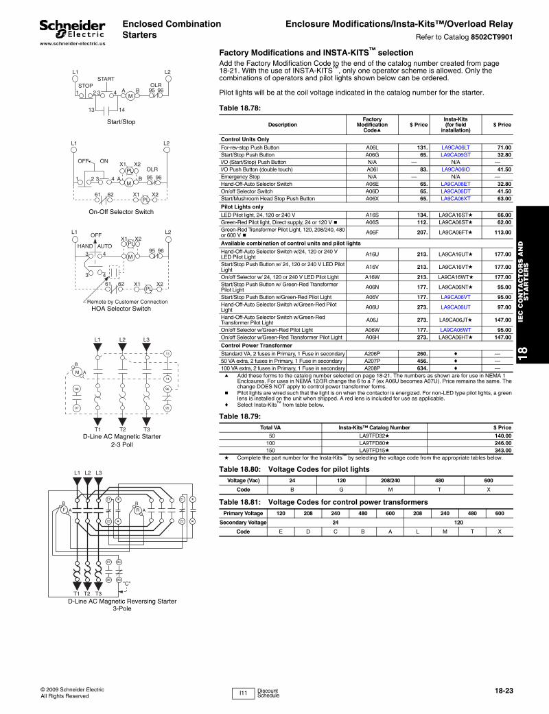
www.schneider-electric.us
18IE
C C
ON
TA
CT
OR
S A
ND
S
TA
RT
ER
S
© 2009 Schneider ElectricAll Rights Reserved
18-23
Enclosed Combination Starters
Enclosure Modifications/Insta-Kits™/Overload RelayRefer to Catalog 8502CT9901
Factory Modifications and INSTA-KITS™ selection Add the Factory Modification Code to the end of the catalog number created from page 18-21. With the use of INSTA-KITS™, only one operator scheme is allowed. Only the combinations of operators and pilot lights shown below can be ordered.
Pilot lights will be at the coil voltage indicated in the catalog number for the starter.
L1 L2
PL
M
OFF ON
1 2 3 4 A B
OLR
95 96
X1 X2
PL61 62 X1 X2
L1 L2
M
HAND AUTO
OFF
PLX1 X2
3 4
3 4
95 96
61 62PL
X1 X2
Remote by Customer Connection
L1 L2START
STOP1 2 A B3 4
M95 96
13 14
OLR
Start/Stop
On-Off Selector Switch
HOA Selector Switch
L1 L2 L3
M
98
97
B
A
96
95
13
14
T1 T2 T3D-Line AC Magnetic Starter
2-3 Poll
L1 L2 L3
21
22
+
+
B
A
B
AF R
T1 T2 T3
21
22
+
+
97
98 96
95
"C"
D-Line AC Magnetic Reversing Starter3-Pole
Table 18.78:
DescriptionFactory
ModificationCodea
$ PriceInsta-Kits (for field
installation)$ Price
Control Units Only
For-rev-stop Push Button A06L 131. LA9CA06LT 71.00Start/Stop Push Button A06G 65. LA9CA06GT 32.80I/O (Start/Stop) Push Button N/A — N/A —I/O Push Button (double touch) A06I 83. LA9CA06IO 41.50Emergency Stop N/A — N/A —Hand-Off-Auto Selector Switch A06E 65. LA9CA06ET 32.80On/off Selector Switch A06D 65. LA9CA06DT 41.50Start/Mushroom Head Stop Push Button A06X 65. LA9CA06XT 63.00
Pilot Lights only
LED Pilot light, 24, 120 or 240 V A16S 134. LA9CA16STd 66.00Green-Red Pilot light, Direct supply, 24 or 120 V b A06S 112. LA9CA06STd 62.00Green-Red Transformer Pilot Light, 120, 208/240, 480 or 600 V b A06F 207. LA9CA06FTd 113.00
Available combination of control units and pilot lights
Hand-Off-Auto Selector Switch w/24, 120 or 240 V LED Pilot Light A16U 213. LA9CA16UTd 177.00
Start/Stop Push Button w/ 24, 120 or 240 V LED Pilot Light A16V 213. LA9CA16VTd 177.00
On/off Selector w/ 24, 120 or 240 V LED Pilot Light A16W 213. LA9CA16WTd 177.00Start/Stop Push Button w/ Green-Red Transformer Pilot Light A06N 177. LA9CA06NTd 95.00
Start/Stop Push Button w/Green-Red Pilot Light A06V 177. LA9CA06VT 95.00Hand-Off-Auto Selector Switch w/Green-Red Pilot Light A06U 273. LA9CA06UT 97.00
Hand-Off-Auto Selector Switch w/Green-Red Transformer Pilot Light A06J 273. LA9CA06JTd 147.00
On/off Selector w/Green-Red Pilot Light A06W 177. LA9CA06WT 95.00On/off Selector w/Green-Red Transformer Pilot Light A06H 273. LA9CA06HTd 147.00
Control Power Transformer
Standard VA, 2 fuses in Primary, 1 Fuse in secondary A206P 260. c —50 VA extra, 2 fuses in Primary, 1 Fuse in secondary A207P 456. c —100 VA extra, 2 fuses in Primary, 1 Fuse in secondary A208P 634. c —a Add these forms to the catalog number selected on page 18-21. The numbers as shown are for use in NEMA 1
Enclosures. For uses in NEMA 12/3R change the 6 to a 7 (ex A06U becomes A07U). Price remains the same. The change DOES NOT apply to control power transformer forms.
b Pilot lights are wired such that the light is on when the contactor is energized. For non-LED type pilot lights, a green lens is installed on the unit when shipped. A red lens is included for use as applicable.
c Select Insta-Kits™ from table below.
Table 18.79: Total VA Insta-Kits™ Catalog Number $ Price
50 LA9TFD32d 140.00100 LA9TFD80d 246.00150 LA9TFD15d 343.00
d Complete the part number for the Insta-Kits™ by selecting the voltage code from the appropriate tables below.
Table 18.80: Voltage Codes for pilot lightsVoltage (Vac) 24 120 208/240 480 600
Code B G M T X
Table 18.81: Voltage Codes for control power transformersPrimary Voltage 120 208 240 480 600 208 240 480 600
Secondary Voltage 24 120
Code E D C B A L M T X
I11 Discount Schedule
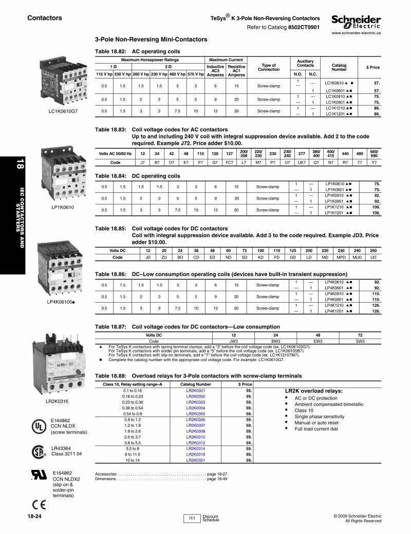
www.schneider-electric.us
18IE
C C
ON
TA
CT
OR
S A
ND
S
TA
RT
ER
S
18-24 © 2009 Schneider ElectricAll Rights Reserved
Contactors TeSys® K 3-Pole Non-Reversing Contactors
Refer to Catalog 8502CT9901
3-Pole Non-Reversing Mini-Contactors
,
Accessories . . . . . . . . . . . . . . . . . . . . . . . . . . . . . . . . . . . . . . . . . . page 18-27Dimensions. . . . . . . . . . . . . . . . . . . . . . . . . . . . . . . . . . . . . . . . . . . page 18-49
LC1K0610G7
Table 18.82: AC operating coilsMaximum Horsepower Ratings Maximum Current
Type ofConnection
AuxiliaryContacts Catalog
Number $ Price1 Ø 3 Ø InductiveAC3
Amperes
ResistiveAC1
Amperes115 V hp 230 V hp 200 V hp 230 V hp 460 V hp 575 V hp N.O. N.C.
0.5 1.5 1.5 1.5 3 3 6 15 Screw-clamp1— — LC1K0610 a b 57.
1 LC1K0601 ab 57.
0.5 1.5 2 3 5 5 9 20 Screw-clamp1 — LC1K0910 ab 75.— 1 LC1K0901 ab 75.
0.5 1.5 3 3 7.5 10 12 20 Screw-clamp1 — LC1K1210 ab 86.— 1 LC1K1201 ab 86.
Table 18.83: Coil voltage codes for AC contactorsUp to and including 240 V coil with integral suppression device available. Add 2 to the code required. Example J72. Price adder $10.00.
Volts AC 50/60 Hz 12 24 42 48 110 120 127 200/208
220/230 230 230/
240 277 380/400
400/415 440 480 660/
690
Code J7 B7 D7 E7 F7 G7 FC7 L7 M7 P7 U7 UE7 Q7 N7 R7 T7 Y7
Table 18.84: DC operating coils
0.5 1.5 1.5 1.5 3 3 6 15 Screw-clamp1 — LP1K0610 ab 75.— 1 LP1K0601 ab 75.
0.5 1.5 2 3 5 5 9 20 Screw-clamp1 — LP1K0910 ab 92.— 1 LP1K0901 ab 92.
0.5 1.5 3 3 7.5 10 12 20 Screw-clamp1 — LP1K1210 ab 106.— 1 LP1K1201 ab 106.
Table 18.85: Coil voltage codes for DC contactorsCoil with integral suppression device available. Add 3 to the code required. Example JD3. Price adder $10.00.
Volts DC 12 20 24 36 48 60 72 100 110 125 200 220 230 240 250
Code JD ZD BD CD ED ND SD KD FD GD LD MD MPD MUD UD
Table 18.86: DC–Low consumption operating coils (devices have built-in transient suppression)
0.5 1.5 1.5 1.5 3 3 6 15 Screw-clamp1 — LP4K0610 ab 92.— 1 LP4K0601 ab 92.
0.5 1.5 2 3 5 5 9 20 Screw-clamp1 — LP4K0910 ab 110.— 1 LP4K0901 ab 110.
0.5 1.5 3 3 7.5 10 12 20 Screw-clamp1 — LP4K1210 ab 126.— 1 LP4K1201 ab 126.
Table 18.87: Coil voltage codes for DC contactors—Low consumptionVolts DC 12 24 48 72
Code JW3 BW3 EW3 SW3a For TeSys K contactors with spring terminal clamps, add a “3” before the coil voltage code (ex. LC1K06103G7).
For TeSys K contactors with solder pin terminals, add a “5” before the coil voltage code (ex. LC1K09105B7).For TeSys K contactors with slip-on terminals, add a “7” before the coil voltage code (ex. LC1K12107M7).
b Complete the catalog number with the appropriate coil voltage code. For example: LC1K0610G7.
Table 18.88: Overload relays for 3-Pole contactors with screw-clamp terminals Class 10, Relay setting range–A Catalog Number $ Price
0.1 to 0.16 LR2K0301 59. LR2K overload relays:• AC or DC protection• Ambient compensated bimetallic• Class 10• Single phase sensitivity• Manual or auto reset• Full load current dial
0.16 to 0.23 LR2K0302 59.0.23 to 0.36 LR2K0303 59.0.36 to 0.54 LR2K0304 59.0.54 to 0.8 LR2K0305 59.0.8 to 1.2 LR2K0306 59.1.2 to 1.8 LR2K0307 59.1.8 to 2.6 LR2K0308 59.2.6 to 3.7 LR2K0310 59.3.8 to 5.5 LR2K0312 59.5.5 to 8 LR2K0314 59.8 to 11.5 LR2K0316 59.10 to 14 LR2K0321 59.
LP1K0610
LP4K06105●
LR2K0316
E164862CCN NLDX(screw terminals)
LR43364Class 3211 04
E164862CCN NLDX2 (slip-on & solder-pin terminals)
I11 Discount Schedule
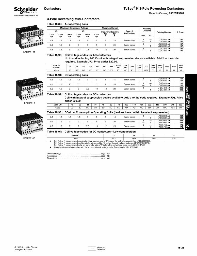
www.schneider-electric.us
18IE
C C
ON
TA
CT
OR
S A
ND
S
TA
RT
ER
S
© 2009 Schneider ElectricAll Rights Reserved
18-25
Contactors TeSys® K 3-Pole Reversing ContactorsRefer to Catalog 8502CT9901
3-Pole Reversing Mini-Contactors
Overload Relays . . . . . . . . . . . . . . . . . . . . . . . . . . . . . . . . . . . . . . .page 18-24Accessories . . . . . . . . . . . . . . . . . . . . . . . . . . . . . . . . . . . . . . . . . . .page 18-27Dimensions . . . . . . . . . . . . . . . . . . . . . . . . . . . . . . . . . . . . . . . . . . .page 18-49
LC2K09107
LP2K0910
LP2K09105
Table 18.89: AC operating coilsMaximum Horsepower Ratings Maximum Current
Type ofConnection
AuxiliaryContacts
Catalog Number $ Price1Ø 3Ø InductiveAC3
A
ResistiveAC1
A115Vhp
230Vhp
200Vhp
230Vhp
460Vhp
575Vhp N.O. N.C.
0.5 1.5 1.5 1.5 3 3 6 15 Screw-clamp 1 — LC2K0610 ab 130.— 1 LC2K0601 ab 130.
0.5 1.5 2 3 5 5 9 20 Screw-clamp 1 — LC2K0910 ab 167.— 1 LC2K0901 ab 167.
0.5 1.5 3 3 7.5 10 12 20 Screw-clamp 1 — LC2K1210 ab 191.— 1 LC2K1201 ab 191.
Table 18.90: Coil voltage codes for AC contactorsUp to and including 240 V coil with integral suppression device available. Add 2 to the code required. Example J72. Price adder $20.00.
Volts AC50/60 Hz 12 24 42 48 110 120 127 200/2
08220/230 230 230/
240 277 380/400
400/415 440 480 660/
690
Code J7 B7 D7 E7 F7 G7 FC7 L7 M7 P7 U7 UE7 Q7 N7 R7 T7 Y7
Table 18.91: DC operating coils
0.5 1.5 1.5 1.5 3 3 6 15 Screw-clamp 1 — LP2K0610 ab 167.— 1 LP2K0601 ab 167.
0.5 1.5 2 3 5 5 9 20 Screw-clamp 1 — LP2K0910 ab 202.— 1 LP2K0901 ab 202.
0.5 1.5 3 3 7.5 10 12 20 Screw-clamp 1 — LP2K1210 ab 232.— 1 LP2K1201 ab 232.
Table 18.92: Coil voltage codes for DC contactors Coil with integral suppression device available. Add 3 to the code required. Example JD3. Price adder $20.00.
Volts DC 12 20 24 36 48 60 72 100 110 125 200 220 230 240 250
Code JD ZD BD CD ED ND SD KD FD GD LD MD MPD MUD UD
Table 18.93: DC–Low Consumption Operating Coils (devices have built-in transient suppression)
0.5 1.5 1.5 1.5 3 3 6 15 Screw-clamp 1 — LP5K0610 ab 202.— 1 LP5K0601 ab 202.
0.5 1.5 2 3 5 5 9 20 Screw-clamp 1 — LP5K0910 ab 238.— 1 LP5K0901 ab 238.
0.5 1.5 3 3 7.5 10 12 20 Screw-clamp 1 — LP5K1210 ab 274.— 1 LP5K1201 ab 274.
Table 18.94: Coil voltage codes for DC contactors—Low consumptionVolts DC 12 24 48 72
Code JW3 BW3 EW3 SW3a For TeSys K contactors with spring terminal clamps, add a “3” before the coil voltage code (ex. LP2K09103BD).
For TeSys K contactors with solder pin terminals, add a “5” before the coil voltage code (ex. LP5K09105BW3).For TeSys K contactors with slip-on terminals, add a “7” before the coil voltage code (ex. LC2K06107B7).
b Complete the catalog number with the appropriate coil voltage code. For example: LC1K0610G7.
I11 Discount Schedule
www.schneider-electric.us
18IE
C C
ON
TA
CT
OR
S A
ND
S
TA
RT
ER
S
18-26 © 2009 Schneider ElectricAll Rights Reserved
Contactors TeSys® K 4-Pole ContactorsRefer to Catalog 8502CT9901
Overload Relays. . . . . . . . . . . . . . . . . . . . . . . . . . . . . . . . . . . . . . . page 18-24Accessories . . . . . . . . . . . . . . . . . . . . . . . . . . . . . . . . . . . . . . . . . . page 18-27Dimensions. . . . . . . . . . . . . . . . . . . . . . . . . . . . . . . . . . . . . . . . . . . page 18-49
LC2K090045
Table 18.95: AC Operating CoilsMaximum Horsepower Ratings Maximum Current
Type of Connection
Power Poles Catalog
Number $ Price1 PH 3 PH InductiveAC3
A
ResistiveAC1
A115 V
hp230 V
hp200 V
hp230 V
hp460 V
hp575 V
hp N.O. N.C.
4-Pole Mini Contactor
0.5 1.5 2 3 5 5 9 15 Screw-clamp 4 — LC1K09004 ab 75.2 2 LC1K09008 ab 81.
0.5 1.5 3 3 7.5 10 12 20 Screw-clamp 4 — LC1K12004 ab 86.
4-Pole Mechanically Interlocked Contactors
0.5 1.5 2 3 5 5 9 20 Screw-clamp 4 — LC2K09004 ab 167.0.5 1.5 3 3 7.5 10 12 20 Screw-clamp 4 — LC2K12004 ab 191.
Table 18.96: Coil voltage codes for AC contactorsUp to and including 240 V coil with integral suppression device available. Add 2 to the code required. Example J72. Price adder $10.00 ($20.00 for mechanically interlocked contactors)
Volts AC 50/60 Hz 12 24 42 48 110 120 127 200/208 220/230 230 230/ 240 277 380/400 400/415 440 480 660/690Code J7 B7 D7 E7 F7 G7 FC7 L7 M7 P7 U7 UE7 Q7 N7 R7 T7 Y7
Table 18.97: DC operating coils4-Pole Mini Contactor
0.5 1.5 2 3 5 5 9 15 Screw-clamp 4 — LP1K09004 ab 92.2 2 LP1K09008 ab 98.
0.5 1.5 3 3 7.5 10 12 20 Screw-clamp 4 — LP1K12004 ab 106.
4-Pole Mechanically Interlocked Contactors
0.5 1.5 2 3 5 5 9 20 Screw-clamp 4 — LP2K09004 ab 202.0.5 1.5 3 3 7.5 10 12 20 Screw-clamp 4 — LP2K12004 ab 232.
Table 18.98: Coil voltage codes for DC contactorsCoil with integral suppression device available. Add 3 to the code required. Example JD3. Price adder $10.00 ($20.00 for mechanically interlocked contactors)
Volts DC 12 20 24 36 48 60 72 100 110 125 200 220 230 240 250
Code JD ZD BD CD ED ND SD KD FD GD LD MD MPD MUD UD
Table 18.99: DC–Low consumption operating coils (devices have built-in transient suppression) 4-Pole Mini Contactor
0.5 1.5 2 3 5 5 9 15 Screw-clamp 4 — LP4K09004 ab 110.2 2 LP4K09008 ab 116.
0.5 1.5 3 3 7.5 10 12 20 Screw-clamp 4 — LP4K12004 ab 126.
4-Pole Mechanically Interlocked Contactors
0.5 1.5 2 3 5 5 9 20 Screw-clamp 4 — LP5K09004 ab
238.
0.5 1.5 3 3 7.5 10 12 20 Screw-clamp 4 — LP5K12004 ab 274.
Table 18.100: Coil voltages for DC contactors—Low consumptionVolts DC 12 24 48 72
Code JW3 BW3 EW3 SW3a For TeSys K contactors with spring terminal clamps, add a “3” before the coil voltage code (ex. LC1K09103L7).
For TeSys K contactors with solder pin terminals, add a “5” before the coil voltage code (ex. LP4K06015JW3).For TeSys K contactors with slip-on terminals, add a “7” before the coil voltage code (ex. LP2K090047BD).
b Complete the catalog number with the appropriate coil voltage code. For example: LC1K0610G7.
I11 Discount Schedule
www.schneider-electric.us
18IE
C C
ON
TA
CT
OR
S A
ND
S
TA
RT
ER
S
© 2009 Schneider ElectricAll Rights Reserved
18-27
Contactors and Accessories
TeSys® K Contactors and AccessoriesRefer to Catalog 8502CT9901
LA1KN11
LA1KN22
E164862CCN NLDX
LR43364Class 3211 04
Table 18.101: Instantaneous auxiliary contact blocksClip-on front mounting, 1 block per contactor and 2 blocks per pair of mechanically interlocked contactors.
Type of connectionAuxiliary Contacts Catalog
Number $ PriceN.O. N.C.
Screw clamp
2 — LA1KN20 14.20— 2 LA1KN02 14.201 1 LA1KN11 14.204 — LA1KN40 a 27.303 1 LA1KN31 a 27.302 2 LA1KN22 a 27.301 3 LA1KN13 a 27.30— 4 LA1KN04 a 27.30
Slip-on 1 x .250" or 2 x .110"
2 — LA1KN207 14.20— 2 LA1KN027 14.201 1 LA1KN117 14.204 — LA1KN407 a 27.303 1 LA1KN317 a 27.302 2 LA1KN227 a 27.301 3 LA1KN137a 27.30— 4 LA1KN047 a 27.30
a Block of 4 contacts cannot be used with LP4K or LP5K contactors.
LA2KT2U
Table 18.102: Electronic time delay auxiliary contact blocksClip-on front mounting, 1 block per contactor and 2 blocks per pair of mechanically interlocked contactors.
Voltage (V) Type Timing Range(S) Contacts Catalog
Number $ Price
24 to 48 Vac or Vdc On-delay 1 to 30 SPDT LA2KT2E 32.80110 to 240 Vac On-delay 1 to 30 SPDT LA2KT2U 32.80
Note: Relay outputs, with single pole double throw, 240 Vac/dc, 2 A max.
Note: Maximum switching capacity 250 VA / 150 W
Note: Operating temperature: -10 to + 60°C (14 to 140°F)
Note: Reset time: 1.5 s during time delay, 0.5 after time delay
Table 18.103: Suppressor Module with incorporated LED indicatorClip-on front mounting
Voltage range Type Sold inlots of
CatalogNumber
$ Priceeach
12 to 24 Vac and dc Varistor 5 LA4KE1B b 9.8032 to 48 Vac and dc Varistor 5 LA4KE1E b 9.8050 to 129 Vac and dc Varistor 5 LA4KE1FC b 9.80130 to 250 Vac and dc Varistor 5 LA4KE1UG b 9.8012 to 24 Vdc Diode + Zener 5 LA4KC1B c 9.8032 to 48 Vdc Diode + Zener 5 LA4KC1E c 9.80220 to 250 Vac RC 5 LA4KA1U d 9.80b Protection by limitation of the transient voltage to 2 Uc maximum. Maximum reduction of the transient voltage peaks. Slight time delay on drop-out (1.1
to 1.5 times normal).c No overvoltage or oscillation frequency. Polarized component. Slight time delay on drop-out (1.1 to 1.5 times normal).d Protection by limitation of the transient voltage to 3 Uc maximum and limitation of the oscillation frequency. Slight time delay on drop-out
(1.2 times normal).
Table 18.104: Paralleling Links
Description Sold inlots of
CatalogNumber
$ Priceeach
For 2 poles with screw-clamp terminals 4 LA9E01 2.20For 4 poles with screw-clamp terminals 2 LA9E02 3.50
Table 18.105: Power Connectors
Description Sold inlots of
CatalogNumber
$ Priceeach
Set of 6 power connections for reversing contactors with screw-clamp terminals 100 LA9K0969 6.20
Set of 4 power connections for changeover contactors with screw-clamp terminals 100 LA9K0970 6.20
Table 18.106: Marking strips
Description Sold inlots of
CatalogNumber
$ Priceeach
Clips onto front of the contactor 100 LA9D90 .06
Table 18.107: Accessories for overload relaysDescription Type of Connection Catalog Number $ Price
Terminal block for separate clip-on mounting of the overload relay onto 35 mmomega rail (AM1DP200) Screw-clamp LA7K0064 11.90
I11 Discount Schedule
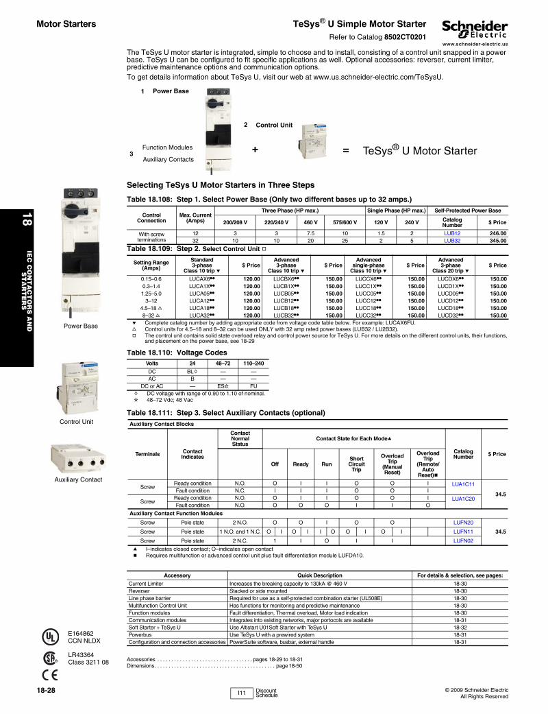
www.schneider-electric.us
18IE
C C
ON
TA
CT
OR
S A
ND
S
TA
RT
ER
S
18-28 © 2009 Schneider ElectricAll Rights Reserved
The TeSys U motor starter is integrated, simple to choose and to install, consisting of a control unit snapped in a power base. TeSys U can be configured to fit specific applications as well. Optional accessories: reverser, current limiter, predictive maintenance options and communication options.To get details information about TeSys U, visit our web at www.us.schneider-electric.com/TeSysU.
Selecting TeSys U Motor Starters in Three Steps
Accessories . . . . . . . . . . . . . . . . . . . . . . . . . . . . . . . . . . pages 18-29 to 18-31Dimensions. . . . . . . . . . . . . . . . . . . . . . . . . . . . . . . . . . . . . . . . . . . page 18-50
Table 18.108: Step 1. Select Power Base (Only two different bases up to 32 amps.)
ControlConnection
Max. Current(Amps)
Three Phase (HP max.) Single Phase (HP max.) Self-Protected Power Base
200/208 V 220/240 V 460 V 575/600 V 120 V 240 V CatalogNumber $ Price
With screw terminations
12 3 3 7.5 10 1.5 2 LUB12 246.0032 10 10 20 25 2 5 LUB32 345.00
Table 18.109: Step 2. Select Control Unit g
Setting Range(Amps)
Standard 3-phase
Class 10 trip e$ Price
Advanced 3-phase
Class 10 trip e$ Price
Advanced single-phase
Class 10 trip e$ Price
Advanced 3-phase
Class 20 trip e$ Price
0.15–0.6 LUCAX6•• 120.00 LUCBX6•• 150.00 LUCCX6•• 150.00 LUCDX6•• 150.000.3–1.4 LUCA1X•• 120.00 LUCB1X•• 150.00 LUCC1X•• 150.00 LUCD1X•• 150.001.25–5.0 LUCA05•• 120.00 LUCB05•• 150.00 LUCC05•• 150.00 LUCD05•• 150.00
3–12 LUCA12•• 120.00 LUCB12•• 150.00 LUCC12•• 150.00 LUCD12•• 150.004.5–18 f LUCA18•• 120.00 LUCB18•• 150.00 LUCC18•• 150.00 LUCD18•• 150.008–32 f LUCA32•• 120.00 LUCB32•• 150.00 LUCC32•• 150.00 LUCD32•• 150.00
e Complete catalog number by adding appropriate code from voltage code table below. For example: LUCAX6FU.f Control units for 4.5–18 and 8–32 can be used ONLY with 32 amp rated power bases (LUB32 / LU2B32).g The control unit contains solid state overload relay and control power source for TeSys U. For more details on the different control units, their functions,
and placement on the power base, see 18-29
Table 18.110: Voltage CodesVolts 24 48–72 110–240
DC BLh — —AC B — —
DC or AC — ESi FUh DC voltage with range of 0.90 to 1.10 of nominal.i 48–72 Vdc; 48 Vac
Table 18.111: Step 3. Select Auxiliary Contacts (optional)Auxiliary Contact Blocks
Terminals Contact Indicates
Contact Normal Status
Contact State for Each Modea
CatalogNumber $ Price
Off Ready RunShort Circuit
Trip
Overload Trip
(Manual Reset)
Overload Trip
(Remote/Auto
Reset)b
ScrewReady condition N.O. O I I O O I LUA1C11
34.5Fault condition N.C. I I I O O I
ScrewReady condition N.O. O I I O O I LUA1C20Fault condition N.O. O O O I I O
Auxiliary Contact Function Modules
Screw Pole state 2 N.O. O O I O O LUFN20
34.5Screw Pole state 1 N.O. and 1 N.C. O I O I I O O I O I LUFN11
Screw Pole state 2 N.C. 1 I O I I LUFN02
a I–indicates closed contact; O–indicates open contactb Requires multifunction or advanced control unit plus fault differentiation module LUFDA10.
Accessory Quick Description For details & selection, see pages:
Current Limiter Increases the breaking capacity to 130kA @ 460 V 18-30Reverser Stacked or side mounted 18-30Line phase barrier Required for use as a self-protected combination starter (UL508E) 18-30Multifunction Control Unit Has functions for monitoring and predictive maintenance 18-30Function modules Fault differentiation, Thermal overload, Motor load indication 18-30Communication modules Integrates into existing networks, major portocols are available 18-31Soft Starter + TeSys U Use Altistart U01Soft Starter with TeSys U 18-32Powerbus Use TeSys U with a prewired system 18-31Configuration and connection accessories PowerSuite software, busbar, external handle 18-31
Control Unit
Function Modules
Auxiliary Contacts
+
Power Base
TeSys® U Motor Starter=
1
2
3
Power Base
Control Unit
Auxiliary Contact
E164862CCN NLDX
LR43364Class 3211 08
Motor Starters TeSys® U Simple Motor StarterRefer to Catalog 8502CT0201
I11 Discount Schedule
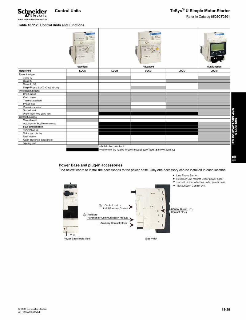
www.schneider-electric.us
18IE
C C
ON
TA
CT
OR
S A
ND
S
TA
RT
ER
S
© 2009 Schneider ElectricAll Rights Reserved
18-29
Control Units TeSys® U Simple Motor StarterRefer to Catalog 8502CT0201
Power Base and plug-in accessoriesFind below where to install the accessories to the power base. Only one accessory can be installed in each location.
Table 18.112: Control Units and Functions
Standard Advanced Multifunction
Reference LUCA LUCB LUCC LUCD LUCM
Protection typeClass 10Class 20Class 5…30Single Phase: LUCC Class 10 only
Protection functionsShort circuitOver currentThermal overloadPhase lossPhase imbalanceGround faultUnder load, long start, jam
Control functionsManual resetAutomatic or local/remote resetFault differentiationThermal alarmMotor load displayFault historyAlarm Threshold adjustmentTripping test
= built-in the control unit= works with the related function modules (see Table 18.119 on page 30)
Control Unit orMultifunction Control
Auxiliary Function or Communication Module
Auxiliary Contact Block
Control CircuitContact Block
b Line Phase Barriere Reverser Unit mounts under power basej Current Limiter attaches under power basem Multifunction Control Unit
m ��
�
Power Base (front view)
b
e j
Side View
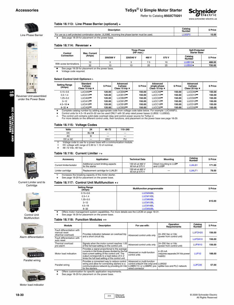
www.schneider-electric.us
18IE
C C
ON
TA
CT
OR
S A
ND
S
TA
RT
ER
S
18-30 © 2009 Schneider ElectricAll Rights Reserved
Accessories TeSys® U Simple Motor StarterRefer to Catalog 8502CT0201
Table 18.113: Line Phase Barrier (optional) a
Description CatalogNumber $ Price
For use as a self protected combination starter, UL508E, incoming line phase barrier must be used. LU9SP0 15.00a See page 18-29 for placement on the power base.
Table 18.114: Reverser b
ControlConnection
Max. Current(Amps)
Three Phase(HP max.)
Self-ProtectedStarter Base
200/208 V 220/240 V 460 V 575 V CatalogNumber $ Price
With screw terminations12 3 3 7.5 10 LU2B12c 488.0032 10 10 20 25 LU2B32c 720.00
b See page 18-29 for placement on the power base.c Voltage code required.
Select Control Unit Optionsef
Setting Range(Amps)
Standard 3-phase
Class 10 trip d$ Price
Advanced 3-phase
Class 10 trip d$ Price
Advanced single-phase
Class 10 trip d$ Price
Advanced 3-phase
Class 20 trip d$ Price
0.15–0.6 LUCAX6•• 120.00 LUCBX6•• 150.00 LUCCX6•• 150.00 LUCDX6•• 150.000.3–1.4 LUCA1X•• 120.00 LUCB1X•• 150.00 LUCC1X•• 150.00 LUCD1X•• 150.001.25–5.0 LUCA05•• 120.00 LUCB05•• 150.00 LUCC05•• 150.00 LUCD05•• 150.00
3–12 LUCA12•• 120.00 LUCB12•• 150.00 LUCC12•• 150.00 LUCD12•• 150.004.5–18 d LUCA18•• 120.00 LUCB18•• 150.00 LUCC18•• 150.00 LUCD18•• 150.008–32 d LUCA32•• 120.00 LUCB32•• 150.00 LUCC32•• 150.00 LUCD32•• 150.00
d Complete catalog number by adding appropriate code from voltage code table below. For example: LUCAX6FU.e Control units for 4.5–18 and 8–32 can be used ONLY with 32 amp rated power bases (LUB32 / LU2B32).f The control unit contains solid state overload relay and control power source for TeSys U.
For more details on the different control units, their functions, and placement on the power base see page 18-29.
Table 18.115: Voltage CodesVolts 24 48–72 110–240
DC BLgb — —AC B — —
DC or AC — ESj FUg Voltage code to use for a power base with a communication module.h DC voltage with range of 0.90 to 1.10 of nominal.i 48–72 Vdc; 48 Vac
Table 18.116: Current Limiter jk
Accessory Application Technical Data Mounting CatalogNumber $ Price
Current limiter/isolator Additional current limiting aspects for the starter
130 kA at 460 V60 kA at 575 V
Direct mounting to LUB• and LU2B• LUALB1 171.00
Limiter cartridge Replacement cartridge for LUALB1 130 kA at 460 V65 kA at 575 V — LUALF1 78.00
j Increases the breaking capacity of the motor starter.k See page 18-29 for placement on the power base.
Table 18.117: Control Unit Multifunction lmSetting Range
(Amps) Multifunction programmable $ Price
0.15–0.6 LUCMX6BL
615.00
0.3–1.4 LUCM1XBL1.25–5.0 LUCM05BL
3–12 LUCM12BL4.5–18 LUCM18BL8–32 LUCM32BL
l Offers motor management system capabilities. For more details see the LUCM on page 18-31.m See page 18-29 for placement on the power base.
Table 18.118: Function Modules no
Module Description For use with: Operation Requirements
CatalogNumber $ Price
Fault differentiation with manual reset (thermal overload) Provides indication between an overload trip
and a short circuit trip. Advanced control units only 24–250 Vac or Vdc (power from control unit)
LUFDH20 156.00
Fault differentiation with auto reset LUFDA10 156.00
Thermal overload pre-alarm
Signals when the motor current reaches 1.05 of the full load setting on the control unit. Advanced control units only 24–250 Vac or Vdc
(power from control unit) LUFW10 156.00
Motor load indication
Provides a signal proportional to the average currents in the three phases divided by the full load current setting of the control unit. The output corresponds to a load status of 0–2 times the full load setting of the control unit.
Advanced or multi-function control units
4–20 mA (requires separate 24 Vdc power supply)
LUFV2 188.00
Parallel wiring
Provides a convenient way to reduce control wiring and allow for connecting starters to a communications network by providing 24 Vdc for the starters.
Advanced or multi-function control units(24 Vdc only) and LU9BN11C or LU9MRC pre-wired connector
LU9G02 splitter box and PLC network LUFC00 57.00
n Offers customization for specific application requirements. o See page 18-29 for placement on the power base.
Line Phase Barrier
Reverser Unit assembled under the Power Base
Current Limiter and its Cartridge
Control UnitMultifunction
Motor load indicator
Alarm differentiation
Parallel wiring
I11 Discount Schedule
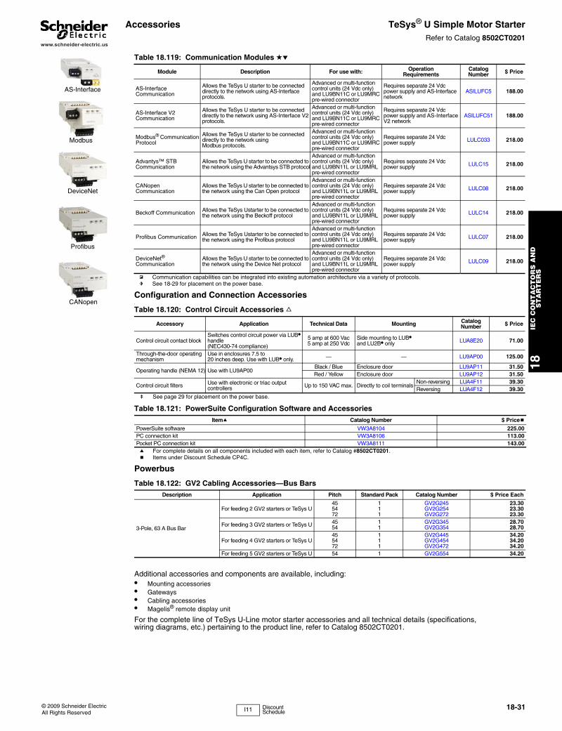
www.schneider-electric.us
18IE
C C
ON
TA
CT
OR
S A
ND
S
TA
RT
ER
S
© 2009 Schneider ElectricAll Rights Reserved
18-31
Accessories TeSys® U Simple Motor StarterRefer to Catalog 8502CT0201
Configuration and Connection Accessories\
Powerbus
Additional accessories and components are available, including:• Mounting accessories• Gateways• Cabling accessories• Magelis® remote display unit
For the complete line of TeSys U-Line motor starter accessories and all technical details (specifications, wiring diagrams, etc.) pertaining to the product line, refer to Catalog 8502CT0201.
Table 18.119: Communication Modules de
Module Description For use with: Operation Requirements
CatalogNumber $ Price
AS-Interface Communication
Allows the TeSys U starter to be connected directly to the network using AS-Interface protocols.
Advanced or multi-function control units (24 Vdc only) and LU9BN11C or LU9MRC pre-wired connector
Requires separate 24 Vdc power supply and AS-Interface network
ASILUFC5 188.00
AS-Interface V2 Communication
Allows the TeSys U starter to be connected directly to the network using AS-Interface V2 protocols.
Advanced or multi-function control units (24 Vdc only) and LU9BN11C or LU9MRC pre-wired connector
Requires separate 24 Vdc power supply and AS-Interface V2 network
ASILUFC51 188.00
Modbus® Communication Protocol
Allows the TeSys U starter to be connected directly to the network using Modbus protocols.
Advanced or multi-function control units (24 Vdc only) and LU9BN11C or LU9MRC pre-wired connector
Requires separate 24 Vdc power supply LULC033 218.00
Advantys™ STB Communication
Allows the TeSys U starter to be connected to the network using the Advantsys STB protocol
Advanced or multi-function control units (24 Vdc only) and LU9BN11L or LU9MRL pre-wired connector
Requires separate 24 Vdc power supply LULC15 218.00
CANopen Communication
Allows the TeSys U starter to be connected to the network using the Can Open protocol
Advanced or multi-function control units (24 Vdc only) and LU9BN11L or LU9MRL pre-wired connector
Requires separate 24 Vdc power supply LULC08 218.00
Beckoff Communication Allows the TeSys Ustarter to be connected to the network using the Beckoff protocol
Advanced or multi-function control units (24 Vdc only) and LU9BN11L or LU9MRL pre-wired connector
Requires separate 24 Vdc power supply LULC14 218.00
Profibus Communication Allows the TeSys Ustarter to be connected to the network using the Profibus protocol
Advanced or multi-function control units (24 Vdc only) and LU9BN11L or LU9MRL pre-wired connector
Requires separate 24 Vdc power supply LULC07 218.00
DeviceNet® Communication
Allows the TeSys U starter to be connected to the network using the Device Net protocol
Advanced or multi-function control units (24 Vdc only) and LU9BN11L or LU9MRL pre-wired connector
Requires separate 24 Vdc power supply LULC09 218.00
p Communication capabilities can be integrated into existing automation architecture via a variety of protocols.q See 18-29 for placement on the power base.
Table 18.120: Control Circuit Accessories f
Accessory Application Technical Data Mounting CatalogNumber $ Price
Control circuit contact blockSwitches control circuit power via LUB• handle (NEC430-74 compliance)
5 amp at 600 Vac5 amp at 250 Vdc
Side mounting to LUB• and LU2B• only LUA8E20 71.00
Through-the-door operating mechanism
Use in enclosures 7.5 to20 inches deep. Use with LUB• only. — — LU9AP00 125.00
Operating handle (NEMA 12) Use with LU9AP00Black / Blue Enclosure door LU9AP11 31.50Red / Yellow Enclosure door LU9AP12 31.50
Control circuit filters Use with electronic or triac output controllers Up to 150 VAC max. Directly to coil terminals
Non-reversing LUA4F11 39.30Reversing LUA4F12 39.30
r See page 29 for placement on the power base.
Table 18.121: PowerSuite Configuration Software and AccessoriesItema Catalog Number $ Priceb
PowerSuite software VW3A8104 225.00PC connection kit VW3A8106 113.00Pocket PC connection kit VW3A8111 143.00a For complete details on all components included with each item, refer to Catalog #8502CT0201.b Items under Discount Schedule CP4C.
Table 18.122: GV2 Cabling Accessories—Bus BarsDescription Application Pitch Standard Pack Catalog Number $ Price Each
3-Pole, 63 A Bus Bar
For feeding 2 GV2 starters or TeSys U455472
111
GV2G245GV2G254GV2G272
23.3023.3023.30
For feeding 3 GV2 starters or TeSys U 45 1 GV2G345 28.7054 1 GV2G354 28.70
For feeding 4 GV2 starters or TeSys U455472
111
GV2G445GV2G454GV2G472
34.2034.2034.20
For feeding 5 GV2 starters or TeSys U 54 1 GV2G554 34.20
AS-Interface
Modbus
DeviceNet
Profibus
CANopen
I11 Discount Schedule
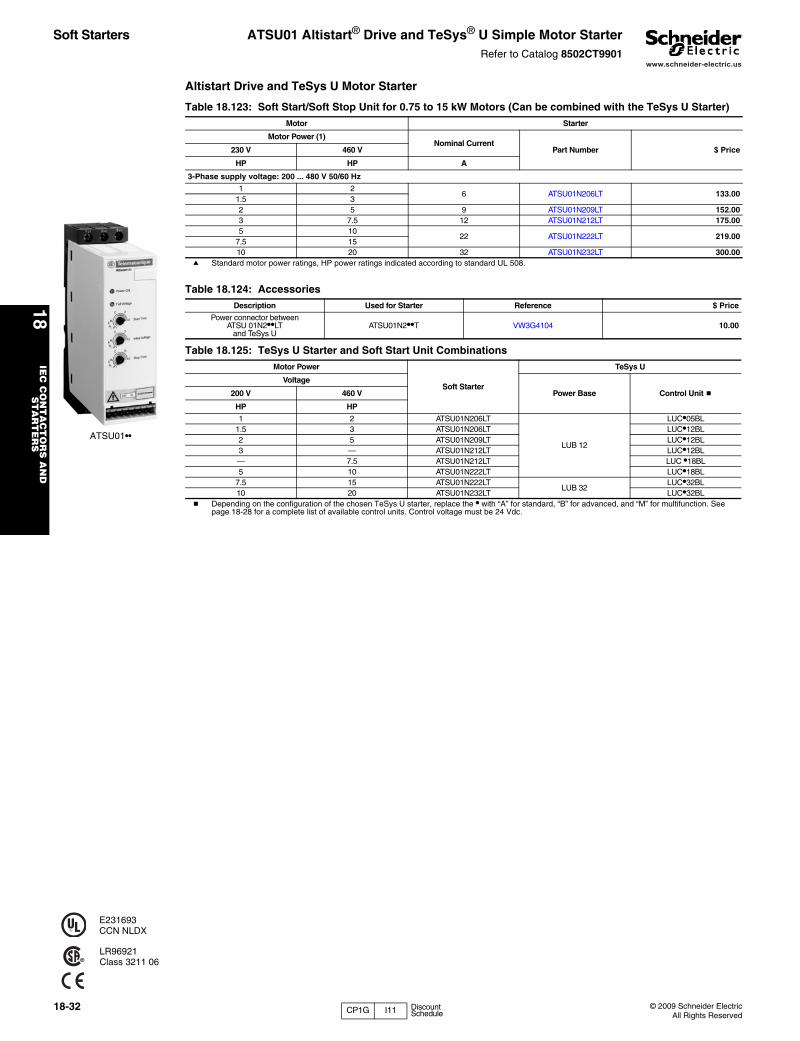
www.schneider-electric.us
18IE
C C
ON
TA
CT
OR
S A
ND
S
TA
RT
ER
S
18-32 © 2009 Schneider ElectricAll Rights Reserved
Soft Starters ATSU01 Altistart® Drive and TeSys® U Simple Motor StarterRefer to Catalog 8502CT9901
Altistart Drive and TeSys U Motor Starter
ATSU01••
E231693CCN NLDX
LR96921Class 3211 06
Table 18.123: Soft Start/Soft Stop Unit for 0.75 to 15 kW Motors (Can be combined with the TeSys U Starter)Motor Starter
Motor Power (1)Nominal Current
Part Number $ Price230 V 460 V
HP HP A
3-Phase supply voltage: 200 ... 480 V 50/60 Hz
1 26 ATSU01N206LT 133.00
1.5 32 5 9 ATSU01N209LT 152.003 7.5 12 ATSU01N212LT 175.005 10
22 ATSU01N222LT 219.007.5 1510 20 32 ATSU01N232LT 300.00
a Standard motor power ratings, HP power ratings indicated according to standard UL 508.
Table 18.124: AccessoriesDescription Used for Starter Reference $ Price
Power connector betweenATSU 01N2••LT
and TeSys UATSU01N2••T VW3G4104 10.00
Table 18.125: TeSys U Starter and Soft Start Unit CombinationsMotor Power
Soft Starter
TeSys U
Voltage
Power Base Control Unit b200 V 460 V
HP HP
1 2 ATSU01N206LT
LUB 12
LUC•05BL1.5 3 ATSU01N206LT LUC•12BL2 5 ATSU01N209LT LUC•12BL3 — ATSU01N212LT LUC•12BL— 7.5 ATSU01N212LT LUC •18BL5 10 ATSU01N222LT LUC•18BL
7.5 15 ATSU01N222LTLUB 32
LUC•32BL10 20 ATSU01N232LT LUC•32BL
b Depending on the configuration of the chosen TeSys U starter, replace the • with “A” for standard, “B” for advanced, and “M” for multifunction. See page 18-28 for a complete list of available control units. Control voltage must be 24 Vdc.
CP1G I11 Discount Schedule
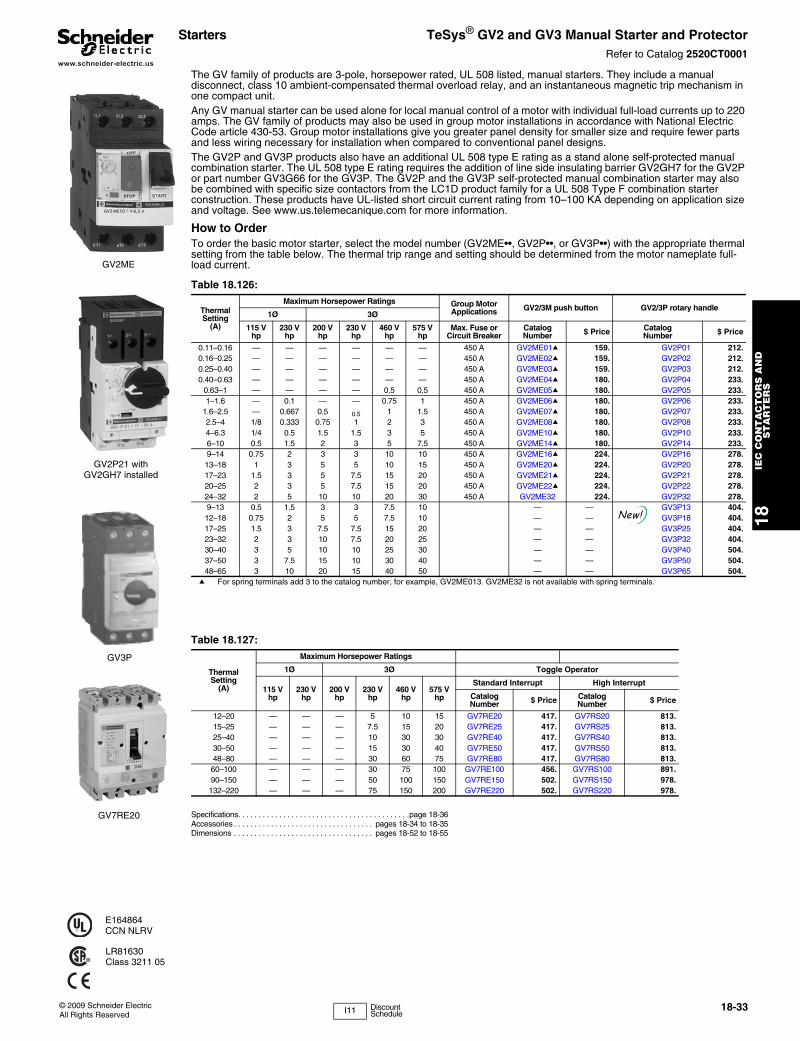
www.schneider-electric.us
18IE
C C
ON
TA
CT
OR
S A
ND
S
TA
RT
ER
S
© 2009 Schneider ElectricAll Rights Reserved
18-33
Starters TeSys® GV2 and GV3 Manual Starter and ProtectorRefer to Catalog 2520CT0001
The GV family of products are 3-pole, horsepower rated, UL 508 listed, manual starters. They include a manual disconnect, class 10 ambient-compensated thermal overload relay, and an instantaneous magnetic trip mechanism in one compact unit.Any GV manual starter can be used alone for local manual control of a motor with individual full-load currents up to 220 amps. The GV family of products may also be used in group motor installations in accordance with National Electric Code article 430-53. Group motor installations give you greater panel density for smaller size and require fewer parts and less wiring necessary for installation when compared to conventional panel designs.The GV2P and GV3P products also have an additional UL 508 type E rating as a stand alone self-protected manual combination starter. The UL 508 type E rating requires the addition of line side insulating barrier GV2GH7 for the GV2P or part number GV3G66 for the GV3P. The GV2P and the GV3P self-protected manual combination starter may also be combined with specific size contactors from the LC1D product family for a UL 508 Type F combination starter construction. These products have UL-listed short circuit current rating from 10–100 KA depending on application size and voltage. See www.us.telemecanique.com for more information.
How to OrderTo order the basic motor starter, select the model number (GV2ME••, GV2P••, or GV3P••) with the appropriate thermal setting from the table below. The thermal trip range and setting should be determined from the motor nameplate full-load current.
Specifications. . . . . . . . . . . . . . . . . . . . . . . . . . . . . . . . . . . . . . . . . .page 18-36Accessories . . . . . . . . . . . . . . . . . . . . . . . . . . . . . . . . . . pages 18-34 to 18-35Dimensions . . . . . . . . . . . . . . . . . . . . . . . . . . . . . . . . . . pages 18-52 to 18-55
GV2ME
GV3P
E164864CCN NLRV
LR81630Class 3211 05
GV2P21 withGV2GH7 installed
Table 18.126:
ThermalSetting
(A)
Maximum Horsepower Ratings Group MotorApplications GV2/3M push button GV2/3P rotary handle
1Ø 3Ø
115 Vhp
230 Vhp
200 Vhp
230 Vhp
460 Vhp
575 Vhp
Max. Fuse orCircuit Breaker
CatalogNumber $ Price Catalog
Number $ Price
0.11–0.16 — — — — — — 450 A GV2ME01a 159. GV2P01 212.0.16–0.25 — — — — — — 450 A GV2ME02a 159. GV2P02 212.0.25–0.40 — — — — — — 450 A GV2ME03a 159. GV2P03 212.0.40–0.63 — — — — — — 450 A GV2ME04a 180. GV2P04 233.
0.63–1 — — — — 0.5 0.5 450 A GV2ME05a 180. GV2P05 233.1–1.6 — 0.1 — — 0.75 1 450 A GV2ME06a 180. GV2P06 233.
1.6–2.5 — 0.667 0.5 0.5 1 1.5 450 A GV2ME07a 180. GV2P07 233.2.5–4 1/8 0.333 0.75 1 2 3 450 A GV2ME08a 180. GV2P08 233.4–6.3 1/4 0.5 1.5 1.5 3 5 450 A GV2ME10a 180. GV2P10 233.6–10 0.5 1.5 2 3 5 7.5 450 A GV2ME14a 180. GV2P14 233.9–14 0.75 2 3 3 10 10 450 A GV2ME16a 224. GV2P16 278.13–18 1 3 5 5 10 15 450 A GV2ME20a 224. GV2P20 278.17–23 1.5 3 5 7.5 15 20 450 A GV2ME21a 224. GV2P21 278.20–25 2 3 5 7.5 15 20 450 A GV2ME22a 224. GV2P22 278.24–32 2 5 10 10 20 30 450 A GV2ME32 224. GV2P32 278.9–13 0.5 1.5 3 3 7.5 10 — — GV3P13 404.12–18 0.75 2 5 5 7.5 10 — — GV3P18 404.17–25 1.5 3 7.5 7.5 15 20 — — GV3P25 404.23–32 2 3 10 7.5 20 25 — — GV3P32 404.30–40 3 5 10 10 25 30 — — GV3P40 504.37–50 3 7.5 15 10 30 40 — — GV3P50 504.48–65 3 10 20 15 40 50 — — GV3P65 504.
a For spring terminals add 3 to the catalog number, for example, GV2ME013. GV2ME32 is not available with spring terminals.
Table 18.127:
ThermalSetting
(A)
Maximum Horsepower Ratings
1Ø 3Ø Toggle Operator
115 Vhp
230 Vhp
200 Vhp
230 Vhp
460 Vhp
575 Vhp
Standard Interrupt High Interrupt
CatalogNumber $ Price Catalog
Number $ Price
12–20 — — — 5 10 15 GV7RE20 417. GV7RS20 813.15–25 — — — 7.5 15 20 GV7RE25 417. GV7RS25 813.25–40 — — — 10 30 30 GV7RE40 417. GV7RS40 813.30–50 — — — 15 30 40 GV7RE50 417. GV7RS50 813.48–80 — — — 30 60 75 GV7RE80 417. GV7RS80 813.60–100 — — — 30 75 100 GV7RE100 456. GV7RS100 891.90–150 — — — 50 100 150 GV7RE150 502. GV7RS150 978.132–220 — — — 75 150 200 GV7RE220 502. GV7RS220 978.
New!
GV7RE20
I11 Discount Schedule
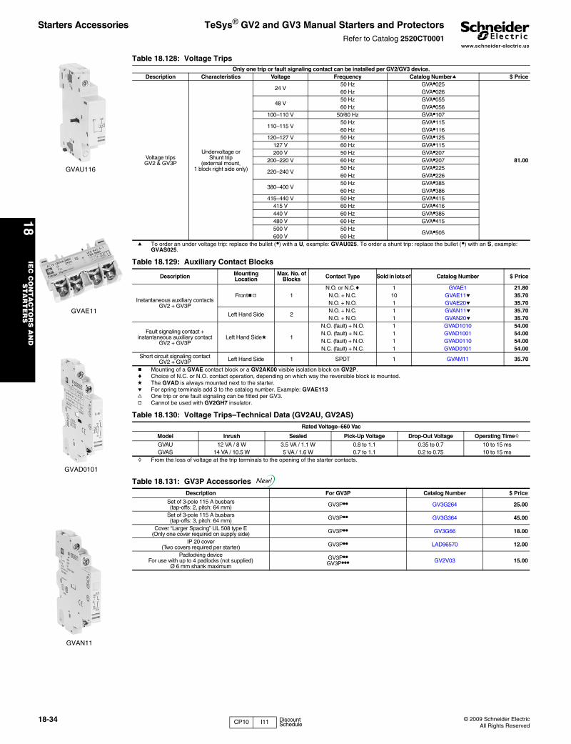
www.schneider-electric.us
18IE
C C
ON
TA
CT
OR
S A
ND
S
TA
RT
ER
S
18-34 © 2009 Schneider ElectricAll Rights Reserved
Starters Accessories TeSys® GV2 and GV3 Manual Starters and ProtectorsRefer to Catalog 2520CT0001
GVAU116
Table 18.128: Voltage TripsOnly one trip or fault signaling contact can be installed per GV2/GV3 device.
Description Characteristics Voltage Frequency Catalog Numbera $ Price
Voltage trips GV2 & GV3P
Undervoltage orShunt trip
(external mount,1 block right side only)
24 V50 Hz GVA•025
81.00
60 Hz GVA•026
48 V50 Hz GVA•05560 Hz GVA•056
100–110 V 50/60 Hz GVA•107
110–115 V50 Hz GVA•11560 Hz GVA•116
120–127 V 50 Hz GVA•125127 V 60 Hz GVA•115200 V 50 Hz GVA•207
200–220 V 60 Hz GVA•207
220–240 V50 Hz GVA•22560 Hz GVA•226
380–400 V50 Hz GVA•38560 Hz GVA•386
415–440 V 50 Hz GVA•415415 V 60 Hz GVA•416440 V 60 Hz GVA•385480 V 60 Hz GVA•415500 V 50 Hz
GVA•505600 V 60 Hz
a To order an under voltage trip: replace the bullet (•) with a U, example: GVAU025. To order a shunt trip: replace the bullet (•) with an S, example: GVAS025.
GVAE11
GVAD0101
GVAN11
Table 18.129: Auxiliary Contact Blocks
Description MountingLocation
Max. No. of Blocks Contact Type Sold in lots of Catalog Number $ Price
Instantaneous auxiliary contactsGV2 + GV3P
Frontbg 1N.O. or N.C.c 1 GVAE1 21.80N.O. + N.C. 10 GVAE11e 35.70N.O. + N.O. 1 GVAE20e 35.70
Left Hand Side 2N.O. + N.C. 1 GVAN11e 35.70N.O. + N.O. 1 GVAN20e 35.70
Fault signaling contact + instantaneous auxiliary contact
GV2 + GV3PLeft Hand Sided 1
N.O. (fault) + N.O. 1 GVAD1010 54.00N.O. (fault) + N.C. 1 GVAD1001 54.00N.C. (fault) + N.O. 1 GVAD0110 54.00N.C. (fault) + N.C. 1 GVAD0101 54.00
Short circuit signaling contact GV2 + GV3P Left Hand Side 1 SPDT 1 GVAM11 35.70
b Mounting of a GVAE contact block or a GV2AK00 visible isolation block on GV2P.c Choice of N.C. or N.O. contact operation, depending on which way the reversible block is mounted.d The GVAD is always mounted next to the starter.e For spring terminals add 3 to the catalog number. Example: GVAE113f One trip or one fault signaling can be fitted per GV3.g Cannot be used with GV2GH7 insulator.
Table 18.130: Voltage Trips–Technical Data (GV2AU, GV2AS)Rated Voltage–660 Vac
Model Inrush Sealed Pick-Up Voltage Drop-Out Voltage Operating Timeh
GVAU 12 VA / 8 W 3.5 VA / 1.1 W 0.8 to 1.1 0.35 to 0.7 10 to 15 msGVAS 14 VA / 10.5 W 5 VA / 1.6 W 0.7 to 1.1 0.2 to 0.75 10 to 15 ms
h From the loss of voltage at the trip terminals to the opening of the starter contacts.
Table 18.131: GV3P Accessories Description For GV3P Catalog Number $ Price
Set of 3-pole 115 A busbars (tap-offs: 2, pitch: 64 mm) GV3P•• GV3G264 25.00
Set of 3-pole 115 A busbars (tap-offs: 3, pitch: 64 mm) GV3P•• GV3G364 45.00
Cover “Larger Spacing” UL 508 type E (Only one cover required on supply side) GV3P•• GV3G66 18.00
IP 20 cover(Two covers required per starter) GV3P•• LAD96570 12.00
Padlocking deviceFor use with up to 4 padlocks (not supplied)
Ø 6 mm shank maximum
GV3P••GV3P••• GV2V03 15.00
New!
CP10 I11 Discount Schedule
www.schneider-electric.us
18IE
C C
ON
TA
CT
OR
S A
ND
S
TA
RT
ER
S
© 2009 Schneider ElectricAll Rights Reserved
18-35
Starters Accessories TeSys® GV7 Manual Starters and ProtectorsRefer to Catalog 2520CT0001
Dimensions . . . . . . . . . . . . . . . . . . . . . . . . . . . . . . . . . . pages 18-52 to 18-55
GV7AE11
Table 18.132: Auxiliary contact blocks (auxiliary contact functions depends on location inside the device)Description Mounting Location Max. No. of Blocks Contact Type Catalog Number $ Price
Standard
InstantaneousInside Device
2 per device N.O. + N.C.GV7AE11 35.70Trip Indication 1 per device N.O. + N.C.
Fault Indication 1 per device N.O. + N.C.
Low Level
InstantaneousInside Device
2 per device N.O. + N.C.GV7AB11 35.70Trip Indication 1 per device N.O. + N.C.
Fault Indication 1 per device N.O. + N.C.
GV7AS055
GV7AD111
Table 18.133: Voltage TripsDescription Mounting Location Max. No. of Blocks Voltage Catalog Number $ Price
Undervoltage Trip Inside Device 1 per device
48 Vac 50 Hz GV7AU055
64.00110–130 Vac 50/60 Hz GV7AU107200–240 Vac 50/60 Hz GV7AU207380–440/480 Vac 50/60 Hz GV7AU387525 Vac 50 Hz GV7AU525
Shunt Trip Inside Device 1 per device
48 Vac 50 Hz GV7AS055
64.00110–130 Vac 50/60 Hz GV7AS107200–240 Vac 50/60 Hz GV7AS207380–440/480 Vac 50/60 Hz GV7AS387525 Vac 50 Hz GV7AS525
Fault Indication Inside Device 1 per device 24–130 GV7AD111 72.00110–415 GV7AD112
GV7AC01
GV7AP03
GV7RE20
GV7AC021 GV7V01
Table 18.134: Wiring AccessoriesDescription Application Catalog Number $ Price
Box LugsSold in lots of 3 for GV7R•20–150i GV7AC021 19.70 eachSold in lots of 3 for GV7R•220i GV7AC022 24.90 each
Phase Barriers, Bus Bars & ShroudsTerminal Extension Kit Increases center distance between phases to 45 mm GV7AC03 46.70Terminal Shroud Kit Covers terminal connections for touch safe protection GV7AC01 41.90Phase Barriers Provides maximum phase separation at connection points GV7AC04 31.10Insulating Barriers Provides insulation between connectors and backplate GV7AC05 24.90
Busbars and CoversConnect to LC1F115–185 contactor GV7AC06 46.70Connect to LC1F225–265 contactor GV7AC07 46.70
Operating Handles and Accessories
Black rotary operating handle with black legend plate (mounts directly on device) GV7AP03 86.00Red rotary operating handle with yellow legend plate (mounts directly on device) GV7AP04 86.00Conversion accessory to mount device directly on panel door GV7AP05 14.00Black rotary operating handle with black legend plate and extension kit (185–600 mm) GV7AP01 102.00Red rotary operating handle with yellow legend plate and extension kit (185–600 mm) GV7AP02 102.00Padlocking device for toggle handle (max. 38 mm padlocks) GV7V01 14.00i Wire size: GV7AC021—#14–3/0; GV7AC022—#14–350 kcmil.
I11 Discount Schedule
www.schneider-electric.us
18IE
C C
ON
TA
CT
OR
S A
ND
S
TA
RT
ER
S
18-36 © 2009 Schneider ElectricAll Rights Reserved
Starters Accessories TeSys® Manual Starters and Protectors LS1 FuseholdersRefer to Catalog 2502CT0001
• 45 mm wide (same dimensions as GV2ME)• Available with screw clamp and spring type terminals• Mounts directly to LC1D09–D32 contactors (with use of GV2AF3 or GV2AF4)• Meets application needs for fusible starter • Uses GV2AE instantaneous contact blocks to open control circuits• DIN rail mounted
LS1D30
Table 18.135:
Description Fuse TypeDimensions
Use In Catalog Number $ PriceIN mm
Spring terminals, 3-pole CC, KTK-R 0.41 x 1.5 10.3 x 38 US Markets LS1D303 86.Screw clamp terminals, 3-pole CC, KTK-R 0.41 x 1.5 10.3 x 38 US Markets LS1D30 86.Spring terminals, 3-pole aM, gG 0.39 x 1.5 10 x 38 European Markets LS1D323 101.Screw clamp terminals, 3-pole aM, gG 0.39 x 1.5 10 x 38 European Markets LS1D32 86.Auxiliary main pole adder aM, gG 0.39 x 1.5 10 x 38 European Markets LA8D324a 65.a Can be mounted on left-hand or right-hand side of the 3-pole LS1D32 block.
Table 18.136: SpecificationsType LS1D30, LS1D303 LS1D32, LS1D323, LS1DT32Max. voltage 600 V 3 PhaseMax. current 30 A
Conforming to standards IEC 60947-1, 60947-2, 60947-4-1, EN60204, BS4841, UL 508, CSA 222.2 No. 14, NFC 63-650, 63-120, 79-130, VDE 0113, 0660
Product approvals UL, CSA BVProtective treatment “TH” “TH”Ambient air temperature—operation
-58 to 158o F(-50 to +70o C)
WiringNumber of conductors and cross sectional area (c.s.a.) Max. Min.
Solid cable 2–#8 AWG (2–6 mm2) 2–#16 (2–1 mm2)Flexible cable without cable end 2–#8 AWG (2–6 mm2) 2–#14 (2–1 mm2)Flexible cable with cable end 2–#10 AWG (2–4 mm2) 2–#16 AWB (2–1 mm2)Resistance to mechanical impact conforming to IEC 60947-1 §7-1-6 0.5 JTightening torque 15 in-lb (1.7 N•m)Sensitivity to phase failure No
Table 18.137: SpecificationsOperating Positions:
Shock resistance—30 g (conforming to IEC 600 68-2-27)Vibration resistance—5 g (5 to 150 Hz) (IEC 600 68-2-26)Ambient temperature:-40 to 176oF (-40 to +80oC) for storage-4 to 140oF (-20 to +60oC) open operation-4 to 104oF (-20 to +40oC) enclosed operation
Rated voltage—600 V
Rated thermal current—25 A (GV2), 63 A (GV3)
Mechanical life:GV2: 100,000 operations
Maximum operating life—25 operations per hourOperating current of magnetic trip is approximately 13 times maximum thermal trip (non-adjustable setting)
30 30 90 90
File LR81630Class 3211 05
File E164864CNN NLRV
I11 Discount Schedule
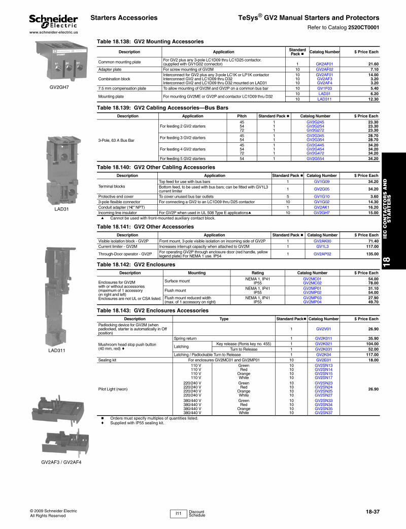
www.schneider-electric.us
18IE
C C
ON
TA
CT
OR
S A
ND
S
TA
RT
ER
S
© 2009 Schneider ElectricAll Rights Reserved
18-37
Starters Accessories TeSys® GV2 Manual Starters and ProtectorsRefer to Catalog 2520CT0001
GV2GH7
LAD31
LAD311
GV2AF3 / GV2AF4
Table 18.138: GV2 Mounting Accessories
Description Application Standard Pack b Catalog Number $ Price Each
Common mounting plate For GV2 plus any 3-pole LC1D09 thru LC1D25 contactor.(supplied with GV1G02 connector) 1 GK2AF01 21.60
Adapter plate For screw mounting of GV2M 10 GV2AF02 7.10
Combination blockInterconnect for GV2 plus any 3-pole LC1K or LP1K contactor 10 GV2AF01 14.00Interconnect GV2 and LC1D09 thru D32 10 GV2AF3 3.20Interconnect GV2 and LC1D09 thru D32 mounted on LAD31 10 GV2AF4 3.20
7.5 mm compensation plate To allow mounting of GV2M and GV2P on a common bus bar 10 GV1F03 5.40
Mounting plate For mounting GV2ME or GV2P and contactor LC1D09 thru D3210 LAD31 6.2010 LAD311 12.30
Table 18.139: GV2 Cabling Accessories—Bus BarsDescription Application Pitch Standard Pack b Catalog Number $ Price Each
3-Pole, 63 A Bus Bar
For feeding 2 GV2 starters455472
111
GV2G245GV2G254GV2G272
23.3023.3023.30
For feeding 3 GV2 starters 45 1 GV2G345 28.7054 1 GV2G354 28.70
For feeding 4 GV2 starters455472
111
GV2G445GV2G454GV2G472
34.2034.2034.20
For feeding 5 GV2 starters 54 1 GV2G554 34.20
Table 18.140: GV2 Other Cabling AccessoriesDescription Application Standard Pack b Catalog Number $ Price Each
Terminal blocksTop feed for use with bus bars 1 GV1G09 34.20Bottom feed, to be used with bus bars; can be fitted with GV1L3 current limiter 1 GV2G05 34.20
Protective end cover To cover unused bus bar outlets 5 GV1G10 3.603-pole flexible connector For connecting a GV2 to an LC1D09 thru D25 contactor 10 GV1G02 14.30Conduit adapter (1•2" NPT) 1 GV2AK1 16.20Incoming line insulator For GV2P when used in UL 508 Type E applicationsa 10 GV2GH7 15.00a Cannot be used with front-mounted auxiliary contact block.
Table 18.141: GV2 Other AccessoriesDescription Application Standard Pack b Catalog Number $ Price Each
Visible isolation block - GV2P Front mount, 3-pole visible isolation on incoming side of GV2P 1 GV2AK00 71.40Current limiter - GV2M Increases interrupt capacity when attached to GV2M 1 GV1L3 117.00
Through-Door operator - GV2P For operating GV2P through enclosure door (red handle, yellow legend plate) For NEMA 1 use. IP54 1 GV2AP02 135.00
Table 18.142: GV2 EnclosuresDescription Mounting Rating Catalog Number $ Price Each
Enclosures for GV2Mwith or without accessories(maximum of 1 accessoryon right and left)Enclosures are not UL or CSA listed.
Surface mount NEMA 1, IP41IP55
GV2MC01GV2MC02
54.0078.00
Flush mount NEMA 1, IP41IP55
GV2MP01GV2MP02
31.1054.00
Flush mount reduced width(max. of 1 accessory on right)
NEMA 1, IP41IP55
GV2MP03GV2MP04
27.9049.70
Table 18.143: GV2 Enclosures AccessoriesDescription Type Standard Packb Catalog Number $ Price Each
Padlocking device for GV2M (when padlocked, starter is automatically in Off position)
1 GV2V01 26.90
Mushroom head stop push button(40 mm, red) c
Spring return 1 GV2K011 35.90
LatchingKey release (Ronis key no. 455) 1 GV2K021 104.00
Turn to Release 1 GV2K031 52.00Latching / Padlockable Turn to Release 1 GV2K04 117.00
Sealing kit For enclosures GV2MC01 and GV2MP01 10 GV2E01 18.00
Pilot Light (neon)
110 V Green 10 GV2SN13
26.90
110 V Red 10 GV2SN14 110 V Orange 10 GV2SN15 110 V White 10 GV2SN17220/240 V Green 10 GV2SN23220/240 V Red 10 GV2SN24220/240 V Orange 10 GV2SN25220/240 V White 10 GV2SN27380/440 V Green 10 GV2SN33380/440 V Red 10 GV2SN34380/440 V Orange 10 GV2SN35380/440 V White 10 GV2SN37
b Orders must specify multiples of quantities listed.c Supplied with IP55 sealing kit.
I11 Discount Schedule
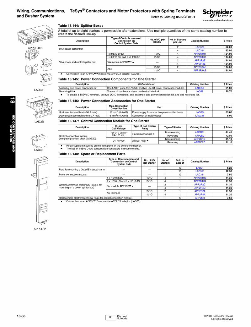
www.schneider-electric.us
18IE
C C
ON
TA
CT
OR
S A
ND
S
TA
RT
ER
S
18-38 © 2009 Schneider ElectricAll Rights Reserved
Wiring, Communications, and Busbar System
TeSys® Contactors and Motor Protectors with Spring TerminalsRefer to Catalog 8502CT0101
APP2R4H1
Table 18.144: Splitter Boxes
A total of up to eight starters is permissible after extensions. Use multiple quantities of the same catalog number to create the desired line-up.
DescriptionType of Control-command
Connection onControl System Side
No. of I/O per Starter
No. of Starters per Unit Catalog Number $ Price
50 A power splitter box — —2 LAD322 52.004 LAD324 93.00
50 A power and control splitter box
1 x HE10 8I/8O 1I/1O 4 APP2R4H1 124.001 x HE10 16I and 1 x HE10 8O 2I/1O 4 APP2R4H2 124.00
Via module APP1C••• a —2 APP2R2E 124.004 APP2R4E 124.00
AS-i 2I/1O 2 APP2R2AS 124.001I/1O 4 APP2R4AS 124.00
a Connection to an APP1C••• module via APP2CX adaptor (LAD35).
LAD35
Table 18.145: Power Connection Components for One StarterDescription Kit Consists of: Catalog Number $ Price
Assembly and power connection kit One LAD31 plate for GV2ME and two LAD34 power connection modules LAD351 21.00Reversing kit b One set of bus bars and one mechanical interlock LAD32 20.70b To create a TeSys D reverser, use two LC1D contactors, one assembly and power connection kit, and one reversing kit.
LAD3B
LAD33
Table 18.146: Power Connection Accessories for One Starter
Description Max. Connection Cross-Section Use Catalog Number $ Price
Upstream terminal block (50 A max) 16 mm2 (6 AWG) Power supply for one or two power splitter boxes LAD3B 83.00Downstream terminal block (50 A max) 6 mm2 (10 AWG) Connection of motor cables LAD331 5.00
APP2D1•
Table 18.147: Control Connection Module for One Starter
Description D-Line Coil Voltage
Type of Coil Control Relay Type of Starter Catalog Number $ Price
Control connection module(integrating contact block GVAE20)
12–240 Vac or 24–125 Vdc Electromechanical c
Non-reversing APP2D1 41.40Reversing APP2D2 72.00
24–48 Vdc Without relay dNon-reversing APP2D1D 31.10
Reversing APP2D2D 31.10c Relay supplied mounted on the front panel of the control connection.d The use of TeSys D low consumption contactors is recommended.
Table 18.148: Spare or Replacement Parts
DescriptionType of Control-command
Connection on Control System Side
No. of I/O per Starter
No. of Starters
Sold in Lots of Catalog Number $ Price
Plate for mounting a GV2ME manual starter — —1 10 LAD31 6.201 10 LAD311 12.30
Power connection module — — 1 10 LAD341 7.50
Control-command splitter box (single, for mounting on a power splitter box)
1 x HE10 8I/8O 1I/1O 4 1 APP2R4H3 11.301 x HE10 16I and 1 x HE10 8O 2I/1O 4 1 APP2R4H4 11.30
Per module APP1C••• e —2 1 APP2R2C 11.304 1 APP2R4C 11.30
AS-Interface2I/1O 2 1 APP2R2A 11.301I/1O 4 1 APP2R4A 11.30
Replacement electromechanical relay (for control connection module) — 1 10 APP2ER 7.50e Connection to an APP1C••• module via APP2CX adaptor (LAD35).
I11 Discount Schedule
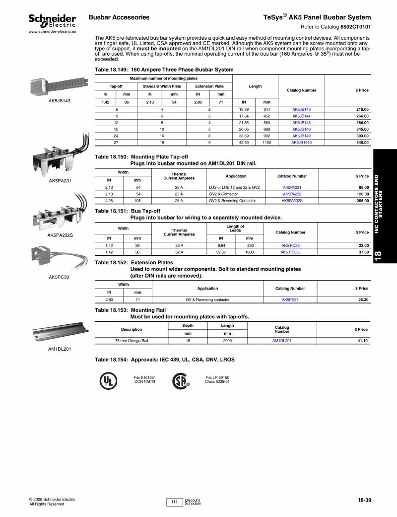
www.schneider-electric.us
18IE
C C
ON
TA
CT
OR
S A
ND
S
TA
RT
ER
S
© 2009 Schneider ElectricAll Rights Reserved
18-39
Busbar Accessories TeSys® AK5 Panel Busbar SystemRefer to Catalog 8502CT0101
The AK5 pre-fabricated bus bar system provides a quick and easy method of mounting control devices. All components are finger safe, UL Listed, CSA approved and CE marked. Although the AK5 system can be screw mounted onto any type of support, it must be mounted on the AM1DL201 DIN rail when component mounting plates incorporating a tap-off are used. When using tap-offs, the nominal operating current of the bus bar (160 Amperes @ 35o) must not be exceeded.
AK5JB143
Table 18.149: 160 Ampere Three Phase Busbar System
Maximum number of mounting plates
LengthCatalog Number $ Price
Tap-off Standard Width Plate Extension Plate
IN mm IN mm IN mm
1.42 36 2.13 54 2.80 71 IN mm
6 4 2 13.39 344 AK5JB143 210.00
9 6 3 17.64 452 AK5JB144 266.00
12 8 4 21.85 560 AK5JB145 286.00
15 10 5 26.05 668 AK5JB146 345.00
24 16 8 38.69 992 AK5JB149 393.00
27 18 9 42.90 1100 AK5JB1410 540.00
AK5PA231
AK5PA232S
Table 18.150: Mounting Plate Tap-offPlugs into busbar mounted on AM1DL201 DIN rail.
Width ThermalCurrent Amperes Application Catalog Number $ Price
IN mm
2.13 54 25 A LUS or LUB 12 and 32 & GV2 AK5PA231 98.00
2.13 54 25 A GV2 & Contactor AK5PA232 120.00
4.25 108 25 A GV2 & Reversing Contactor AK5PA232S 206.00
AK5PC33
Table 18.151: Bus Tap-off Plugs into busbar for wiring to a separately mounted device.
Width ThermalCurrent Amperes
Length ofLeads Catalog Number $ Price
IN mm IN mm
1.42 36 32 A 9.84 250 AK5 PC33 23.00
1.42 36 32 A 39.37 1000 AK5 PC33L 37.80
Table 18.152: Extension PlatesUsed to mount wider components. Bolt to standard mounting plates (after DIN rails are removed).
WidthApplication Catalog Number $ Price
IN mm
2.80 71 GV & Reversing contactor AK5PE27 26.30
Table 18.153: Mounting RailMust be used for mounting plates with tap-offs.
DescriptionDepth Length Catalog
Number $ Pricemm mm
75 mm Omega Rail 15 2000 AM1DL201 41.10
Table 18.154: Approvals: IEC 439, UL, CSA, DNV, LROS
File E161251CCN NMTR
File LR 89150Class 6228-01
AM1DL201
I11 Discount Schedule
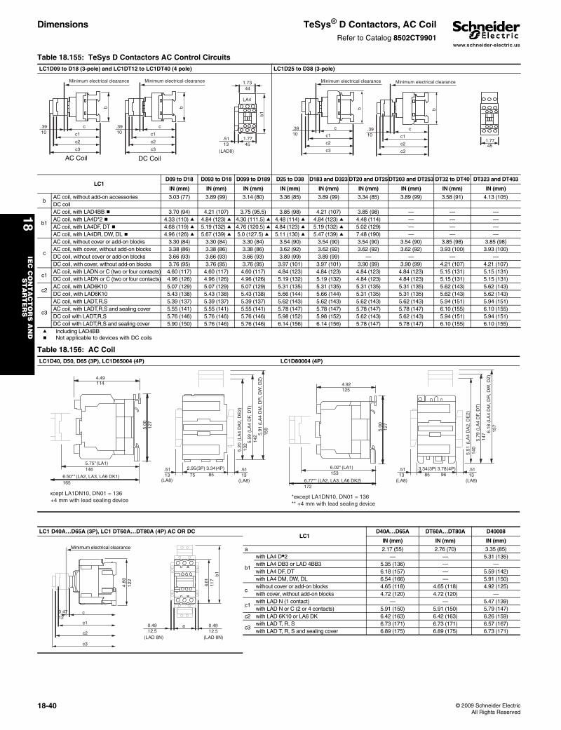
www.schneider-electric.us
18IE
C C
ON
TA
CT
OR
S A
ND
S
TA
RT
ER
S
18-40 © 2009 Schneider ElectricAll Rights Reserved
Dimensions TeSys® D Contactors, AC CoilRefer to Catalog 8502CT9901
Table 18.155: TeSys D Contactors AC Control CircuitsLC1D09 to D18 (3-pole) and LC1DT12 to LC1DT40 (4 pole) LC1D25 to D38 (3-pole)
LC1D09 to D18 D093 to D18 D099 to D189 D25 to D38 D183 and D323 DT20 and DT25DT203 and DT253 DT32 to DT40 DT323 and DT403
IN (mm) IN (mm) IN (mm) IN (mm) IN (mm) IN (mm) IN (mm) IN (mm) IN (mm)
bAC coil, without add-on accessories 3.03 (77) 3.89 (99) 3.14 (80) 3.36 (85) 3.89 (99) 3.34 (85) 3.89 (99) 3.58 (91) 4.13 (105)DC coil
b1
AC coil, with LAD4BB b 3.70 (94) 4.21 (107) 3.75 (95.5) 3.85 (98) 4.21 (107) 3.85 (98) — — —AC coil, with LA4D*2 b 4.33 (110) a 4.84 (123) a 4.30 (111.5) a 4.48 (114) a 4.84 (123) a 4.48 (114) — — —AC coil, with LA4DF, DT b 4.68 (119) a 5.19 (132) a 4.76 (120.5) a 4.84 (123) a 5.19 (132) a 5.02 (129) — — —AC coil, with LA4DR, DW, DL b 4.96 (126) a 5.67 (139) a 5.0 (127.5) a 5.11 (130) a 5.47 (139) a 7.48 (190) — — —
c
AC coil, without cover or add-on blocks 3.30 (84) 3.30 (84) 3.30 (84) 3.54 (90) 3.54 (90) 3.54 (90) 3.54 (90) 3.85 (98) 3.85 (98)AC coil, with cover, without add-on blocks 3.38 (86) 3.38 (86) 3.38 (86) 3.62 (92) 3.62 (92) 3.62 (92) 3.62 (92) 3.93 (100) 3.93 (100)DC coil, without cover or add-on blocks 3.66 (93) 3.66 (93) 3.66 (93) 3.89 (99) 3.89 (99) — — — —DC coil, with cover, without add-on blocks 3.76 (95) 3.76 (95) 3.76 (95) 3.97 (101) 3.97 (101) 3.90 (99) 3.90 (99) 4.21 (107) 4.21 (107)
c1AC coil, with LADN or C (two or four contacts) 4.60 (117) 4.60 (117) 4.60 (117) 4.84 (123) 4.84 (123) 4.84 (123) 4.84 (123) 5.15 (131) 5.15 (131)DC coil, with LADN or C (two or four contacts) 4.96 (126) 4.96 (126) 4.96 (126) 5.19 (132) 5.19 (132) 4.84 (123) 4.84 (123) 5.15 (131) 5.15 (131)
c2AC coil, with LAD6K10 5.07 (129) 5.07 (129) 5.07 (129) 5.31 (135) 5.31 (135) 5.31 (135) 5.31 (135) 5.62 (143) 5.62 (143)DC coil, with LAD6K10 5.43 (138) 5.43 (138) 5.43 (138) 5.66 (144) 5.66 (144) 5.31 (135) 5.31 (135) 5.62 (143) 5.62 (143)
c3
AC coil, with LADT,R,S 5.39 (137) 5.39 (137) 5.39 (137) 5.62 (143) 5.62 (143) 5.62 (143) 5.62 (143) 5.94 (151) 5.94 (151)AC coil, with LADT,R,S and sealing cover 5.55 (141) 5.55 (141) 5.55 (141) 5.78 (147) 5.78 (147) 5.78 (147) 5.78 (147) 6.10 (155) 6.10 (155) DC coil with LADT,R,S 5.76 (146) 5.76 (146) 5.76 (146) 5.98 (152) 5.98 (152) 5.62 (143) 5.62 (143) 5.94 (151) 5.94 (151)DC coil with LADT,R,S and sealing cover 5.90 (150) 5.76 (146) 5.76 (146) 6.14 (156) 6.14 (156) 5.78 (147) 5.78 (147) 6.10 (155) 6.10 (155)
a Including LAD4BBb Not applicable to devices with DC coils
Table 18.156: AC CoilLC1D40, D50, D65 (3P), LC1D65004 (4P) LC1D80004 (4P)
LC1 D40A…D65A (3P), LC1 DT60A…DT80A (4P) AC OR DCLC1
D40A…D65A DT60A…DT80A D40008
IN (mm) IN (mm) IN (mm)
a 2.17 (55) 2.76 (70) 3.35 (85)
b1
with LA4 D•2 — — 5.31 (135)with LA4 DB3 or LAD 4BB3 5.35 (136) — —with LA4 DF, DT 6.18 (157) — 5.59 (142)with LA4 DM, DW, DL 6.54 (166) — 5.91 (150)
cwithout cover or add-on blocks 4.65 (118) 4.65 (118) 4.92 (125)with cover, without add-on blocks 4.72 (120) 4.72 (120) —
c1with LAD N (1 contact) — — 5.47 (139)with LAD N or C (2 or 4 contacts) 5.91 (150) 5.91 (150) 5.79 (147)
c2 with LAD 6K10 or LA6 DK 6.42 (163) 6.42 (163) 6.26 (159)
c3with LAD T, R, S 6.73 (171) 6.73 (171) 6.57 (167)with LAD T, R, S and sealing cover 6.89 (175) 6.89 (175) 6.73 (171)
b
c
c1
c2
c3
1.77
(LAD8)
b1
1.73
LA4
.3910
44
45.5113
Minimum electrical clearance
b
c
c1
c2
c3
.3910
Minimum electrical clearance
AC Coil DC Coil
b
1.77
c.3910 c1
c2
c345
Minimum electrical clearance
b
c.3910 c1
c2
c3
Minimum electrical clearance
xcept LA1DN10, DN01 = 136+4 mm with lead sealing device
(LA2, LA3, LA6 DK1)
5.75*146
(LA1)
6.50**165
4.49114
5.00
127
5.20
132 5.
5914
2 (
LA4
DF,
DT
)
5.91
150
(LA
4 D
M, D
R, D
W, D
Z)
2.95
75.5113
.5113
(LA8) (LA8)
(LA
4 D
A2,
DE
2)
(3P) 3.3485
(4P)
(LA2, LA3, LA6 DK2)
6.02*153
(LA1)
6.77** 172
4.92125
5.00
127
*except LA1DN10, DN01 = 136** +4 mm with lead sealing device
5.51
140
5.79
147
(LA
4 D
F, D
T)
6.18
157
(LA
4 D
M, D
R, D
W, D
Z)
(LA
4 D
A2,
DE
2)
3.3485
.5113
(LA8)
.5113
(LA8)
(3P) 3.7896
(4P)
4.61
117
4.80
122
a
(LAD 8N) (LAD 8N)
0.4912.5
c1
c2
c3
b1
0.4712
c
0.4912.5
Minimum electrical clearance
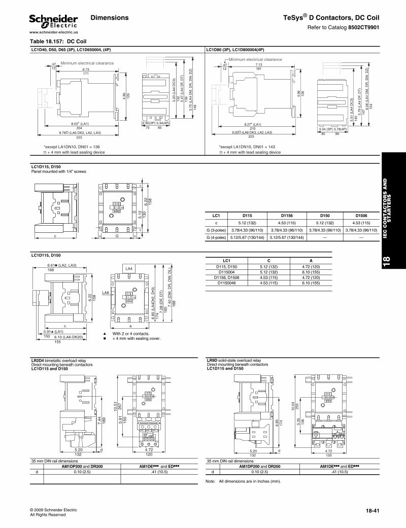
www.schneider-electric.us
18IE
C C
ON
TA
CT
OR
S A
ND
S
TA
RT
ER
S
© 2009 Schneider ElectricAll Rights Reserved
18-41
Dimensions TeSys® D Contactors, DC CoilRefer to Catalog 8502CT9901
Table 18.157: DC CoilLC1D40, D50, D65 (3P), LC1D650004, (4P) LC1D80 (3P), LC1D800004(4P)
LC1D115, D150Panel mounted with 1/4” screws
LC1 D115 D1156 D150 D1506
c 5.12 (132) 4.53 (115) 5.12 (132) 4.53 (115)
G (3-poles) 3.78/4.33 (96/110) 3.78/4.33 (96/110) 3.78/4.33 (96/110) 3.78/4.33 (96/110)
G (4-poles) 5.12/5.67 (130/144) 5.12/5.67 (130/144) — —
LC1D115, D150
LC1 C A
D115, D150 5.12 (132) 4.72 (120)D115004 5.12 (132) 6.10 (155)
D1156, D1506 4.53 (115) 4.72 (120)D1150046 4.53 (115) 6.10 (155)
LR2D4 bimetallic overload relay Direct mounting beneath contactors LC1D115 and D150
LR9D solid-state overload relay Direct mounting beneath contactors LC1D115 and D150
35 mm DIN rail dimensions 35 mm DIN rail dimensions AM1DP200 and DR200 AM1DE••• and ED••• AM1DP200 and DR200 AM1DE••• and ED•••
d 0.10 (2.5) .41 (10.5) d 0.10 (2.5) .41 (10.5)
Note: All dimensions are in Inches (mm).
2.95(3P) 3.34(4P)75 85
5.20
(LA
4 D
C3)
132
5.47
(LA
4 D
F, D
T)
139
5.75
(LA
4 D
M, D
R, D
W, D
Z)
146
.4712 6.73
171
4.96
126
8.03* (LA1)204
8.78d (LA6 DK2, LA2, LA3)223
*except LA1DN10, DN01 = 136 d + 4 mm with lead sealing device
Minimum electrical clearance
8.27* (LA1)210
9.02d (LA6 DK3, LA2, LA3)223
4.96
126
7.13181
.4712
*except LA1DN10, DN01 = 143 d + 4 mm with lead sealing device
3.34 (3P) 3.78(4P)85 96
5.51
(LA
4 D
C3)
140
5.79
(LA
4 D
F, D
T)
147 6.
06 (
LA4
DM
, DR
, DW
, DZ
)15
4
Minimum electrical clearance
130
5.12
==
158
6.22
c G= =
6.22
158
c a
5.91q (LA1)150 6.10 (LA6-DK20)
155
6.61c (LA2, LA3)168
6.85
(LA
4D•2
, D•3
)17
4 7.28
(D
F, D
T)
185 7.
40 (
DM
, DR
, DW
, DL)
188
LA8
LA4
a With 2 or 4 contacts.b + 4 mm with sealing cover.
5.20132
d 4.72120
10.5
126
75.
9115
0
7.44
189
5.20132
4.72120
d
6.85
174
10.0
425
55.
3513
6
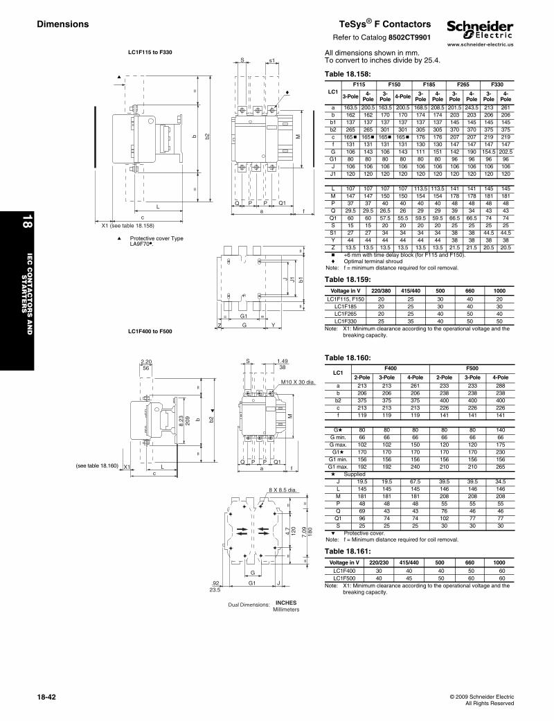
www.schneider-electric.us
18IE
C C
ON
TA
CT
OR
S A
ND
S
TA
RT
ER
S
18-42 © 2009 Schneider ElectricAll Rights Reserved
Dimensions TeSys® F ContactorsRefer to Catalog 8502CT9901
LC1F115 to F330
LC1F400 to F500
All dimensions shown in mm. To convert to inches divide by 25.4.
L
c
b b2
==
X1 (see table 18.158)
a
a Protective cover Type LA9F70•.
S s1
Q P P Q1
a f
M
c
Z
= =G1
G Y
J J1 b1=
=
Table 18.158:
LC1F115 F150 F185 F265 F330
3-Pole 4-Pole
3-Pole 4-Pole 3-
Pole4-
Pole3-
Pole4-
Pole3-
Pole4-
Pole
a 163.5 200.5 163.5 200.5 168.5 208.5 201.5 243.5 213 261b 162 162 170 170 174 174 203 203 206 206b1 137 137 137 137 137 137 145 145 145 145b2 265 265 301 301 305 305 370 370 375 375c 165b 165b 165b 165b 176 176 207 207 219 219f 131 131 131 131 130 130 147 147 147 147G 106 143 106 143 111 151 142 190 154.5 202.5G1 80 80 80 80 80 80 96 96 96 96J 106 106 106 106 106 106 106 106 106 106J1 120 120 120 120 120 120 120 120 120 120
L 107 107 107 107 113.5 113.5 141 141 145 145M 147 147 150 150 154 154 178 178 181 181P 37 37 40 40 40 40 48 48 48 48Q 29.5 29.5 26.5 26 29 29 39 34 43 43Q1 60 60 57.5 55.5 59.5 59.5 66.5 66.5 74 74S 15 15 20 20 20 20 25 25 25 25S1 27 27 34 34 34 34 38 38 44.5 44.5Y 44 44 44 44 44 44 38 38 38 38Z 13.5 13.5 13.5 13.5 13.5 13.5 21.5 21.5 20.5 20.5b +6 mm with time delay block (for F115 and F150).c Optimal terminal shroud
Note: f = minimum distance required for coil removal.
Table 18.159: Voltage in V 220/380 415/440 500 660 1000
LC1F115, F150 20 25 30 40 20LC1F185 20 25 30 40 30LC1F265 20 25 40 50 40LC1F330 25 35 40 50 50
Note: X1: Minimum clearance according to the operational voltage and the breaking capacity.
2.2056
X1c
L
8.23
209 b b2
==
e
(see table 18.160)
S 1.4938
M10 X 30 dia.
Q P P Q1a f
M
8 X 8.5 dia.
G
.9223.5
G1 J
4.7
120
7.09
180
= =
=
=
Dual Dimensions: INCHESMillimeters
Table 18.160:
LC1F400 F500
2-Pole 3-Pole 4-Pole 2-Pole 3-Pole 4-Pole
a 213 213 261 233 233 288b 206 206 206 238 238 238b2 375 375 375 400 400 400c 213 213 213 226 226 226f 119 119 119 141 141 141
Gd 80 80 80 80 80 140G min. 66 66 66 66 66 66G max. 102 102 150 120 120 175G1d 170 170 170 170 170 230
G1 min. 156 156 156 156 156 156G1 max. 192 192 240 210 210 265d Supplied
J 19.5 19.5 67.5 39.5 39.5 34.5L 145 145 145 146 146 146M 181 181 181 208 208 208P 48 48 48 55 55 55Q 69 43 43 76 46 46Q1 96 74 74 102 77 77S 25 25 25 30 30 30
e Protective cover.Note: f = Minimum distance required for coil removal.
Table 18.161: Voltage in V 220/230 415/440 500 660 1000
LC1F400 30 40 40 50 60LC1F500 40 45 50 60 60
Note: X1: Minimum clearance according to the operational voltage and the breaking capacity.
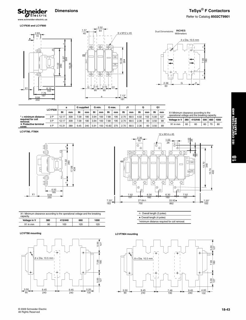
www.schneider-electric.us
18IE
C C
ON
TA
CT
OR
S A
ND
S
TA
RT
ER
S
© 2009 Schneider ElectricAll Rights Reserved
18-43
LC1F630 and LC1F800
LC1F780, F7804
LC1F780 mounting LC1F7804 mounting
18.2
846
4
11.9
730
4
11.0
228
0
2.8372
X1
9.84250
6.10155
7.76197
==
c
10.3
926
4
1.5740
2.5264
6 x M12 x 45
a
Q Q13.1580
3.1580
7.13*
181
2.3860
G J1
7.09
180
==
4 x Dia. 10.5 mm
Dual Dimensions: INCHESMillimeters
LC1F630a G supplied G min. G max. J1 Q Q1
IN mm IN mm IN mm IN mm IN mm IN mm IN mm
* = minimum distancerequired for coil removal.c Protective terminal cover.
2 P 12.17 309 7.09 180 3.94 100 7.68 195 2.70 68.5 4.02 102 5.00 127
3 P 12.17 309 7.09 180 3.94 100 7.68 195 2.70 68.5 2.36 60 3.50 89
4 P 15.31 389 9.45 240 5.91 150 10.83 275 2.70 68.5 2.36 60 3.50 89
X1:Minimum clearance according to the operational voltage and the breaking capacity.
Voltage in V 380 415/440 500 660 1000
X1 in mm 60 60 60 70 80
9.84250
6.50165
X1
11.0
2280
17.0
8434
==
2.3660
12 x M14 x 45
1.0226
7.52191
6.30160
6.30160
7.52191
1.02 26
.86 22
13.7
034
815
.74
400
27.64f 702
33.93a 862
7.20*183
7.20*183
X1: Minimum clearance according to the operational voltage and the breaking capacity.
Voltage in V 380 415/440 660 1000
X1 in mm 90 100 120 120
f Overall length (3 poles)
a Overall length (4 poles)
*minimum distance required for coil removal.
3.5090
9.45240
9.45240
5.20132
5.00
127
7.09
180
5.00
127
6 x Dia. 10.5 mm
3.5090
9.45240
7.48190
9.45240
5.00
127
7.09
180
5.00
127
8 x Dia. 10.5 mm
4.00102
Dimensions TeSys® F ContactorsRefer to Catalog 8502CT9901
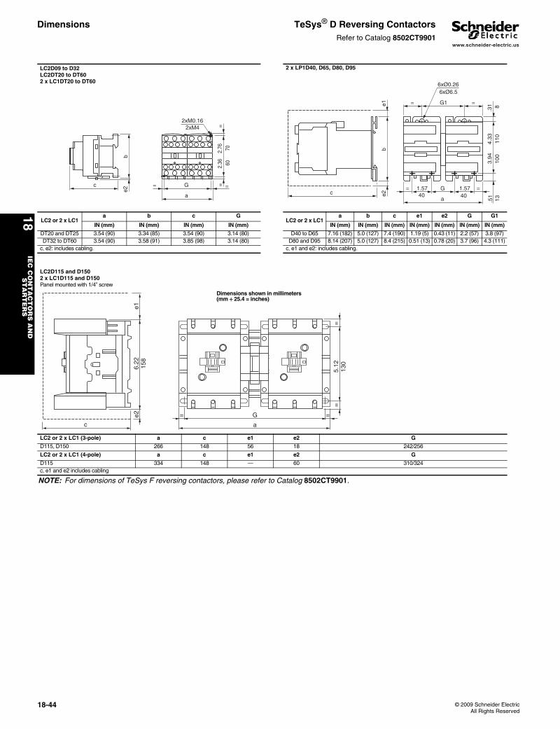
www.schneider-electric.us
18IE
C C
ON
TA
CT
OR
S A
ND
S
TA
RT
ER
S
18-44 © 2009 Schneider ElectricAll Rights Reserved
Dimensions TeSys® D Reversing ContactorsRefer to Catalog 8502CT9901
LC2D09 to D32LC2DT20 to DT602 x LC1DT20 to DT60
2 x LP1D40, D65, D80, D95
LC2 or 2 x LC1a b c G
LC2 or 2 x LC1a b c e1 e2 G G1
IN (mm) IN (mm) IN (mm) IN (mm) IN (mm) IN (mm) IN (mm) IN (mm) IN (mm) IN (mm) IN (mm)
DT20 and DT25 3.54 (90) 3.34 (85) 3.54 (90) 3.14 (80) D40 to D65 7.16 (182) 5.0 (127) 7.4 (190) 1.19 (5) 0.43 (11) 2.2 (57) 3.8 (97)DT32 to DT60 3.54 (90) 3.58 (91) 3.85 (98) 3.14 (80) D80 and D95 8.14 (207) 5.0 (127) 8.4 (215) 0.51 (13) 0.78 (20) 3.7 (96) 4.3 (111)
c, e2: includes cabling. c, e1 and e2: includes cabling.
LC2D115 and D150 2 x LC1D115 and D150 Panel mounted with 1/4” screw
LC2 or 2 x LC1 (3-pole) a c e1 e2 G
D115, D150 266 148 56 18 242/256
LC2 or 2 x LC1 (4-pole) a c e1 e2 G
D115 334 148 — 60 310/324c, e1 and e2 includes cabling
NOTE: For dimensions of TeSys F reversing contactors, please refer to Catalog 8502CT9901.
2xM0.16
G
a
= =
2.36
2.76
==c
be2
6070
2xM4
c
be1
e2
G1= =
6xØ6.5
1.57
a
= =G 1.57
100
6xØ0.26
8.3
113.5
140 40
3.94
110
4.33
6.22
158
e1e2
c
G
a
= =
5.12
130
==
Dimensions shown in millimeters (mm ÷ 25.4 = inches)
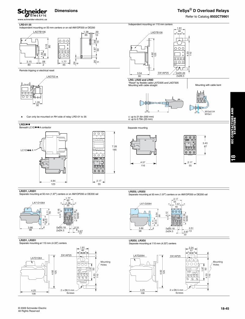
www.schneider-electric.us
18IE
C C
ON
TA
CT
OR
S A
ND
S
TA
RT
ER
S
© 2009 Schneider ElectricAll Rights Reserved
18-45
Dimensions TeSys® D Overload RelaysRefer to Catalog 8502CT9901
LRD-01-35Independent mounting on 50 mm centers or on rail AM1DP200 or DE200
Independent mounting on 110 mm centers
Remote tripping or electrical reset
LRD, LR2D and LR9D“Reset” by flexible cable LA7D305 and LAD7305 Mounting with cable straight Mounting with cable bent
a Can only be mounted on RH side of relay LRD-01 to 35 c: up to 21.6in (550 mm)e: up to 0.79in (20 mm)
LRD3ttBeneath LC1DttA contactor Separate mounting
LR2D1, LR3D1Separate mounting at 50 mm (1.97”) centers or on AM1DP200 or DE200 rail
LR2D2, LR3D2Separate mounting at 50 mm (1.97”) centers or on AM1DP200 or DE200 rail
LR2D1, LR3D1Separate mounting at 110 mm (4.33”) centers
LR2D2, LR3D2Separate mounting at 110 mm (4.33”) centers
1.7745
.082
3.1580
1.50 38
3.15 80
1.97 50
.20 5
LAD7B106 1.3835
.3910
.24 6
.59
15
LAD7B106
4.33
110
==
1.8146 ==
2xØ0.262xØ6.5
DX1AP253.5490
4.92
125
LAD703 a
1.2632
ce M10x0.04eM10x1
1857.28
552.17
1234.84
LC1DppA
1164.57
873.43
552.17
3.8698
1.48
43.5
d
3.11 79
LA7-D1064
0.16 4
1.97
/2.5
650
/65
0.318 0.67
17
2xØ0.182xØ4.5
1.3835
==
1.7745
3.8698
1.71
43.5
d
3.54
90
LA7-D2064
0.12
3
0.51130.87
22
2xØ0.182xØ4.5
1.5740
==
2.1755
1.97
/2.5
650
/65
4.92
125
4.25108
LA7D1064DX1AP25
= =
1.97 50
4.33
110
==
1.8146
2 x Ø6.5 mmScrews
MountingHoles
4.25108
4.92
125
LA7D2064
1.97 50
4.33
110
==
= =
2.2457
DX1AP25
MountingHoles
2 x Ø6.5 mmScrews
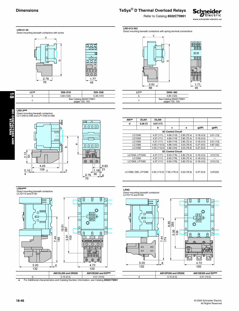
www.schneider-electric.us
18IE
C C
ON
TA
CT
OR
S A
ND
S
TA
RT
ER
S
18-46 © 2009 Schneider ElectricAll Rights Reserved
Dimensions TeSys® D Thermal Overload RelaysRefer to Catalog 8502CT9901
LRD-01-35Direct mounting beneath contactors with screw
LRD-013-353Direct mounting beneath contactors with spring terminal connections
LC1• D09–D18 D25–D38 LC1• D093–383
b 4.84 (123) 5.39 (137) b 4.84 (123)
c See Catalog 8502CT9901pages 122, 123. c See Catalog 8502CT9901
pages 122, 123.
LRD-3•••Direct mounting beneath contactorsLC1-D40 to D95 and LP1-D40 to D80
AM1• DL201 DL200
d 0.28 (7) 0.67 (17)
b c e g(3P) g(4P)
AC Control Circuit
LC1D40 4.37 (111) 4.69 (119) 2.85 (72.4) 0.18 (4.5) 0.51 (13)LC1D50 4.37 (111) 4.69 (119) 2.85 (72.4) 0.18 (4.5) —LC1D65 4.37 (111) 4.69 (119) 2.85 (72.4) 0.18 (4.5) 0.51 (13)LC1D80 4.55 (115.5) 4.88 (124) 3.03 (76.9) 0.37 (9.5) 0.87 (22)LC1D95 4.55 (115.5) 4.88 (124) 3.03 (76.9) 0.37 (9.5) —
DC Control Circuit
LC1D40, LP1D40 4.37 (111) 6.93 (176) 2.85 (72.4) 0.18 (4.5) 0.51(13)LC1D50 4.37 (111) 6.93 (176) 2.85 (72.4) 0.18 (4.5) —
LC1D65, LP1D65 4.37 (111) 6.93 (176) 2.85 (72.4) 0.18 (4.5) 0.51(13)
LC1D80, D95, LP1D80 4.55 (115.5) 7.06 (179.4) 3.03 (76.9) 0.37 (9.5) 0.87(22)
LRD4•••Direct mounting beneath contactorsLC1D115 and D150
LR9DDirect mounting beneath contactorsLC1D115 and D150
AM1DL200 and DR200 AM1DE200 and ED••• AM1DP200 and DR200 AM1DE200 and ED•••d 0.10 (2.5) 0.41 (10.5) d 0.10 (2.5) 0.41 (10.5)
a For Additional characteristics and Catalog Number information, see Catalog 8502CT9901
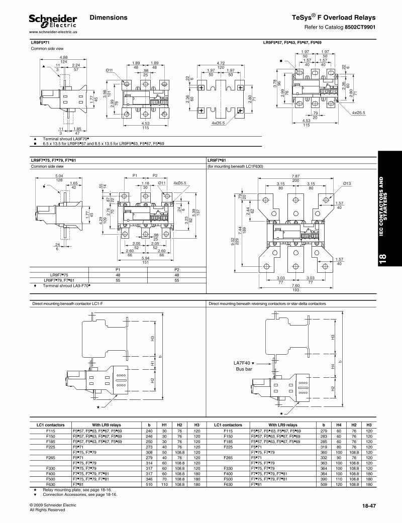
www.schneider-electric.us
18IE
C C
ON
TA
CT
OR
S A
ND
S
TA
RT
ER
S
© 2009 Schneider ElectricAll Rights Reserved
18-47
Dimensions TeSys® F Overload RelaysRefer to Catalog 8502CT9901
LR9F5•71 LR9F5•57, F5•63, F5•67, F5•69
Common side view
a Terminal shroud LA9F70•b 6.5 x 13.5 for LR9F5•57 and 8.5 x 13.5 for LR9F5•63, F5•67, F5•69
LR9F7•75, F7•79, F7•81 LR9F7•81
Common side view (for mounting beneath LC1F630)
P1 P2LR9F7•75 48 48
LR9F7•79, F7•81 55 55c Terminal shroud LA9-F70•
Direct mounting beneath contactor LC1-F Direct mounting beneath reversing contactors or star-delta contactors
2.99 76
1.5740
1.5740
3.78 96
1.9750
1.9750
2.36 60
2.80 71
.22 6
4xØ5.5
4.53115
.7920
c b4.72
120
2.36 60
1.9750
1.9750
2.80 71
Ø11
4xØ5.5
2.2457
1.8547
1.77 45
1.8948
1.8948
.9825
4.53115
.22 6
.113
.113
3.98
101
2.99 76
4.88124
q a
4.29
109
.55
14
1.1830
P2 P1
5.94151
Ø11
2.0552
2.0552
2.6066
2.6066
4xØ5.5
2.76 70
.87
22
.24 6
3.23 82
5.39
137
.9825
1.6542
5.04128
.246
1.77 45
f c
7.44
189
.79
20
7.87200
3.1580
3.1580
7.60193
9.02
229
3.0377
3.0377
2.44 62
Ø13
1.5740
1.5740
H2
b
H3
H1
d
H2
b
H4
H3
LA7F40pBus Bar
d
LA7F40 eBus bar
LC1 contactors With LR9 relays b H1 H2 H3 LC1 contactors With LR9 relays b H4 H2 H3
F115 F5•57, F5•63, F5•67, F5•69 240 30 76 120 F115 F5•57, F5•63, F5•67, F5•69 279 60 76 120F150 F5•57, F5•63, F5•67, F5•69 246 30 76 120 F150 F5•57, F5•63, F5•67, F5•69 283 60 76 120F185 F5•57, F5•63, F5•67, F5•69 250 30 76 120 F185 F5•57, F5•63, F5•67, F5•69 285 60 76 120F225 F5•71 273 40 76 120 F225 F5•71 319 80 76 120
F7•75, F7•79 308 50 108.8 120 F7•75, F7•79 360 100 108.8 120F265 F5•71 279 40 76 120 F265 F5•71 332 90 76 120
F7•75, F7•79 314 60 108.8 120 F7•75, F7•79 363 100 108.8 120F330 F7•75, F7•79 317 60 108.8 120 F330 F7•75, F7•79 364 100 108.8 120F400 F7•75, F7•79, F7•81 317 60 108.8 180 F400 F7•75, F7•79, F7•81 364 100 108.8 180F500 F7•75, F7•79, F7•81 346 70 108.8 180 F500 F7•75, F7•79, F7•81 390 110 108.8 180F630 F7•81 510 110 108.8 180 F630 F7•81 509 120 108.8 180
d Relay mounting plate, see page 18-16.e Connection Accessories, see page 18-16.
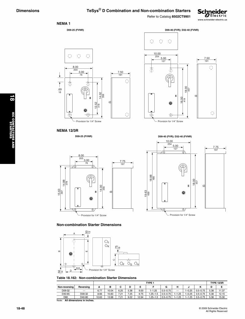
www.schneider-electric.us
18IE
C C
ON
TA
CT
OR
S A
ND
S
TA
RT
ER
S
18-48 © 2009 Schneider ElectricAll Rights Reserved
Dimensions TeSys® D Combination and Non-combination StartersRefer to Catalog 8502CT9901
NEMA 1
NEMA 12/3R
Non-combination Starter Dimensions
Table 18.162: Non-combination Starter DimensionsTYPE 1 TYPE 12/3R
Non-reversing Reversing A B C D E F G H J K D E
D09-32 — 6.77 10.04 6.25 5.38 9.00 1–1.25 0.5–0.75 — 1–0.25 0.5–0.75 5.38 11.37D40-65 D09-32 8.66 10.83 7.21 7.25 9.75 1.25–1.5 0.5–0.75 1–1.25 1–0.25 0.5–0.75 5.38 12.15
D80 D40-80 10.63 13.98 7.21 9.22 12.94 1.25–1.5 0.5–0.75 1–1.25 1–1.25 0.5–0.75 5.38 15.30Note: All dimensions in inches.
7.50191
Provision for 1/4" Screw
.6918
8.00 203
3.0076
14.0
235
6
12.5
231
8
5.00127
16.5
041
9
7.50191
Provision for 1/4" Screw
10.00254
18.0
045
7
R
R
D09-25 (FVNR) D09-40 (FVR); D32-40 (FVNR)
7.75197
Provision for 1/4" Screw
19.6
349
95.00127
Provision for 1/4" Screw
18.8
848
0
7.75197
18.0
045
7
14.0
035
6
15.6
339
714
.88
378
8.00203
3.0076
10.00 254
R
R
D09-25 (FVNR) D09-40 (FVR); D32-40 (FVNR)
R
.56
14
DD/2
Provision for 1/4" Screw
C.7
519
F G H
B E
A .50
13
J
K
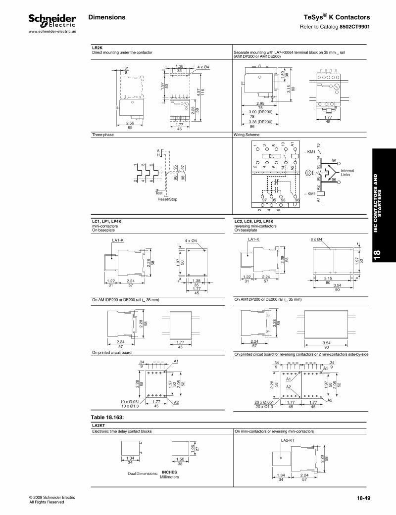
www.schneider-electric.us
18IE
C C
ON
TA
CT
OR
S A
ND
S
TA
RT
ER
S
© 2009 Schneider ElectricAll Rights Reserved
18-49
Dimensions TeSys® K ContactorsRefer to Catalog 8502CT9901
LR2KDirect mounting under the contactor Separate mounting with LA7-K0064 terminal block on 35 mm rail
(AM1DP200 or AM1DE200)
Three-phase Wiring Scheme
.318
2.5665
1.7745
4.57
116
2.28 58
1.97 50
4 x Ø41.3835
2.9575
3.09 (DP200) 783.38 (DE200) 86
1.50 38
3.15 80
1.7745
1 3 5
2 4 6
95 97
96 98
AH
Test
Reset/Stop
Internal Links
1 3 5 13 A1
2 4 6 14 A2
2 4 6
97 95 98 96
– KM1
A2
A1
9695
1314
– KM1
O
95
96
LC1, LP1, LP4Kmini-contactorsOn baseplate
On AM1DP200 or DE200 rail ( 35 mm)
On printed circuit board
LA1-K
2.2457
1.2231
2.28 58
4 x Ø4
1.3835
1.97 50
1.7745
2.2457
2.28 58
1.7745
.349
A1
A2
2.28 58 1.97 50 2.05 52
1.7745
10 x Ø.05110 x Ø1.3
LC2, LC8, LP2, LP5Kreversing mini-contactorsOn baseplate
On AM1DP200 or DE200 rail ( 35 mm)
On printed circuit board for reversing contactors or 2 mini-contactors side-by-side
8 x Ø4
3.1580
3.5490
1.97 50
LA1-K
1.2231
2.28 58
2.2457
2.2457
2.28 58
3.5490
.349
.349A1
A1
A2
A22.28 58 1.97 50 2.05 52
1.7745
1.7745
20 x Ø.05120 x Ø1.3
Table 18.163: LA2KT
Electronic time delay contact blocks On mini-contactors or reversing mini-contactors
1.3434
1.5038
1.06 27
Dual Dimensions: INCHESMillimeters 2.24
571.3434
2.28 58
LA2-KT
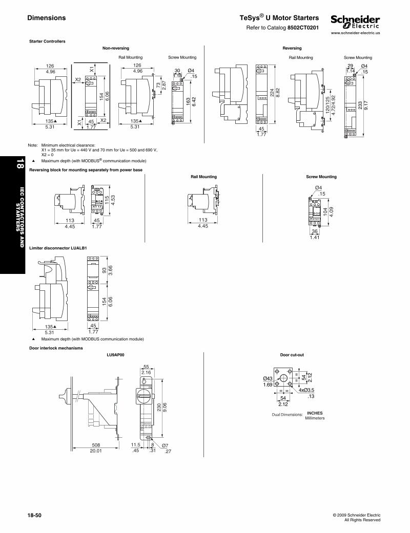
www.schneider-electric.us
18IE
C C
ON
TA
CT
OR
S A
ND
S
TA
RT
ER
S
18-50 © 2009 Schneider ElectricAll Rights Reserved
Dimensions TeSys® U Motor StartersRefer to Catalog 8502CT0201
Starter Controllers
Non-reversing Reversing
Note: Minimum electrical clearance: X1 = 35 mm for Ue = 440 V and 70 mm for Ue = 500 and 690 V,X2 = 0
a Maximum depth (with MODBUS® communication module)
1264.96
135a 5.31
154
6.06
X1
X1 45
1.77
X2
X2
1264.96
135a 5.31
73 2.87
301.18
Ø4 .15
163
6.42
Rail Mounting Screw Mounting
224
8.82
451.77
120/
125
4.72
/4.9
2
233
9.17
291.14
Ø4.15
Rail Mounting Screw Mounting
Reversing block for mounting separately from power base
Rail Mounting Screw Mounting
451.77
1134.45
115
4.53
1134.45
361.41
104
4.09
Ø4 .15
Limiter disconnector LUALB1
a Maximum depth (with MODBUS communication module)
451.77
93 3.66
154
6.06
135a 5.31
Door interlock mechanisms
LU9AP00 Door cut-out
50820.01
11.5.45
8.31
552.16
230
9.06
Ø7 .27
= =
==
54 2.12
542.12
Ø431.69
4xØ3.5.13
Dual Dimensions: INCHESMillimeters
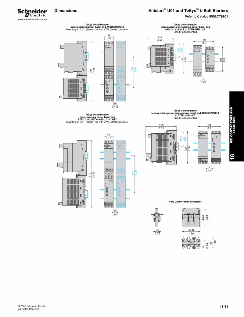
www.schneider-electric.us
18IE
C C
ON
TA
CT
OR
S A
ND
S
TA
RT
ER
S
© 2009 Schneider ElectricAll Rights Reserved
18-51
Dimensions Altistart® U01 and TeSys® U Soft StartersRefer to Catalog 8502CT9901
TeSys U combination (non-reversing power base) and ATSU 01N212LT
Mounting on § (35mm) rail with VW3 G4104 connector
TeSys U combination (non-reversing power base) and
ATSU 01N222LT to ATSU 01N232LTMounting on § (35mm) rail with VW3 G4104 connector
150
5.91
284
11.1
8
451.77
90.354
314
12.3
6
451.77
170
6.69
90.354
TeSys U combination (non-reversing or reversing power base) and
ATSU 01N2206LT to ATSU 01N212LTSide-by-side mounting
TeSys U combination (non-reversing or reversing power base) and ATSU 01N222LT
to ATSU 01N232LTSide-by-side mounting
VW3 G4104 Power connector
993.9
1355.31
154
6.06
72.2
2.84
9
124
4.88
0.354
993.9
1355.31
72.2
2.84
154
6.06
90.354
44.81.76
200.79
6 0.24
46.6
1.83
28 1.10
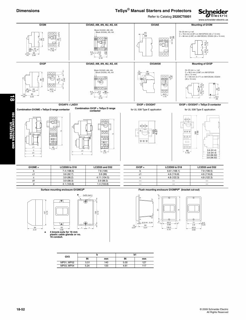
www.schneider-electric.us
18IE
C C
ON
TA
CT
OR
S A
ND
S
TA
RT
ER
S
18-52 © 2009 Schneider ElectricAll Rights Reserved
Dimensions TeSys® Manual Starters and ProtectorsRefer to Catalog 2520CT0001
GV2M GV2AD, AM, AN, AU, AS, AX GV2AE Mounting of GV2M
89
66
4416
11.43
.63 1.73
2.60
3.5
45=
=
44.51.75
1.77
9.3 9.3
81
18.37 .37 .71
3.19
Block GV2AD, AM, ANBlock GV2AU, AS, AX 15
.59
10 .39
c
44.5
44.5
1.75
1.75
On 35 mm railC = 78.5 mm (3.09") on AM1DP200 (35 x 7.5 mm)C = 86 mm (3.39") on AM1DE200, ED200 (35 x 15 mm)
GV2P GV2AD, AM, AN, AU, AS, AX GV2AK00 Mounting of GV2P
89
82
50261.02 1.97
3.23
3.50
44.5
6145
==
1.75
1.77
2.40
.5915
9.3 9.3
81
1818.37 .37
3.19
.71
Block GV2AD, AM, ANBlock GV2AU, AS, AX 9814
.55 3.86
44.5
32 1.26
1.75
44.5
c
44.5
1.75
1.75
13.5
84
.53
3.31
On 35 mm railC = 98.5 mm (3.88") on AM1DP200(35 x 7.5 mm)C = 106 mm (4.17") on AM1DE200, ED200(35 x 15 mm)
GV2AF4 + LAD31 GV2P + GV2GH7 GV2P + GV2GH7 + TeSys D contactor
Combination GV2ME + TeSys D range contactor Combination GV2P + TeSys D range contactor for UL 508 Type E application for UL 508 Type E application
c1
c
d1
d
451.77
b
451.77
b
c1
c10
34.
07
441.73
191
7.50
3.6 (91.4)3.6 (91.4)
3.8 (96.52)3.8 (96.52)
GV2ME + LC2D09 to D18 LC2D25 and D32 GV2P + LC2D09 to D18 LC2D25 and D32
b 7.4 (188.6) 7.8 (199) b 6.61 (168.1) 7.9 (199.5)c1 3.6 (92.7) 3.9 (99) c1 4.6 (116.8) 4.6 (116.8)c 3.9 (98.2) 4.11 (104.5) c 4.8 (122.3) 4.8 (122.3)
d1 3.9 (98.3) 3.9 (98.3) — — —d 4.1 (103.8) 1.4 (103.8) — — —
Surface mounting enclosure GV2MC0• Flush mounting enclosure GV2MP0• (bracket cut-out)
147
843.31
5.79
933.66
2xØ5.3x6.3
=
130
==
=
5.12
a
a 4 knock-outs for 16 mm plastic cable glands or no. 16 conduit.
1...6
84130.51 3.31
/0.04...0.24
b
=b1
= = 93.5 =
106.53.68
4.19
71
92.8
6.52.8
3.65
0.25
GV2 b b1
IN mm IN mm
MP01, MP02 5.51 140 5.00 127MP03, MP04 5.24 133 4.61 117
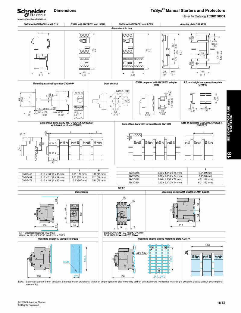
www.schneider-electric.us
18IE
C C
ON
TA
CT
OR
S A
ND
S
TA
RT
ER
S
© 2009 Schneider ElectricAll Rights Reserved
18-53
Dimensions TeSys® Manual Starters and ProtectorsRefer to Catalog 2520CT0001
GV2M with GK2AF01 and LC1K GV2M with GV2AF01 and LC1K GV2M with GV2AF01 and LC2K Adapter plate GK2AF01
dimensions in mm
793.11
45
152
1.77
6.0
152
903.54
6.0
24
5545
135
9.5.94 .37
1.77
2.17
5.31 45
35
54
105
±5
35
Ø5.5
51.38
1.38
1.77
2.13
4.13
±.2
.2
.22
Mounting external operator GV2AP0• Door cut-out GV2M on panel with GV2AF02 adapter plate
7.5 mm height compensation plate GV1F03
min.=150
7
53
65
5.2
= =
1.5...5max.=290
2.56
2.1 5.91
/0.06...0.20
11.42 0.21
.276
54= =
==
54
4xØ3.5 0.14
Ø43 1.7
2.13
2.13
803.15
50/6
0
4.2
351.38
1.97
/2.3
6
.17
130.51
351.38
39 1.54
Sets of bus bars, GV2G445, GV2G454, GV2G472 with terminal block GV2G05 Sets of bus bars with terminal block GV1G09 Sets of bus bars GV2G245, GV2G254,
GV2G272
GV3 P
Dimensions Mounting on rail AM1 DE200 or AM1 ED201
X1 = Electrical clearance (ISC max)40 mm for Ue < 500 V, 50 mm for Ue < 690 V
Blocks GV ANpp , GV ADpp , GV AM11Block GV3 AUpp and GV3 ASpp
Mounting on panel, using M4 screws Mounting on pre-slotted mounting plate AM1 PA
Note: Leave a space of 9 mm between 2 manual motor protectors: either an empty space or side-mounting add-on contact blocks. Horizontal mounting is possible: please consult your regional sales office.
632.5
l3
.12
18.71
p
451.8
301.2
l
I P
GV2G445 0.16 x 1.8" (4 x 45 mm) 7.0" (179 mm) 1.8" (45 mm)GV2G454 0.16 x 2.1" (4 x 54 mm) 8.1" (206 mm) 2.1" (54 mm)GV2G472 0.16 x 1.8" (4 x 45 mm) 10.2" (260 mm) 2.8" (72 mm)
I
GV2G245 0.08 x 1.8" (2 x 45 mm) 3.5" (89 mm)GV2G254 0.08 x 2.1" (2 x 54 mm) 3.9" (98 mm)GV2G272 0.08 x 2.8"(2 x 72 mm) 4.6" (116 mm)GV2G354 0.12 x 2.1" (3 x 54 mm) 6.0" (152 mm)
136
X1
X1
132
6864
559 18
(2)(1)
144
6864
136
3xØ4 137,
5
37,5 136 18,7 18,7
137,
5
AF1 EA4
183
16
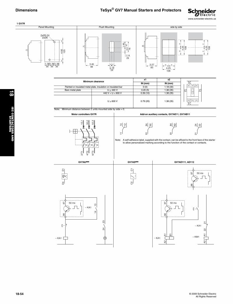
www.schneider-electric.us
18IE
C C
ON
TA
CT
OR
S A
ND
S
TA
RT
ER
S
18-54 © 2009 Schneider ElectricAll Rights Reserved
Dimensions TeSys® GV7 Manual Starters and Protectors
1 GV7R
Panel Mounting Flush Mounting side by side
1.3835
1.3835
1.3835
=4.
9212
5=
2xØ0.242xØ6
= =
1.1429
1.1429
1.85 47
3.0
76
3.4688
3.2783
==
4.25
108
4.25
108
= =
4.25108
==
Minimum clearancex1 x2
IN (mm) IN (mm)
Painted or insulated metal plate, insulation or insulated bar 0 (0) 1.18 (30)Bare metal plate U < 440 V 0.20 (5) 1.38 (35)
440 V < U < 600 V 0.39 (10) 1.38 (35)
U > 600 V 0.79 (20) 1.38 (35)
Note: Minimum distance between 2 units mounted side by side = 0.
Motor controllers GV7R Add-on auxiliary contacts, GV7AE11, GV7AB11
Note: A self-adhesive label, supplied with the contact, can be affixed to the front face of the starter to allow personalized marking according to the function of the contact or contacts.
GV7AU••• GV7AS••• GV7AD111, AD112
x1x1
x2x2
2/T
1
4/T
2
6/T
3
1/L1
3/L2
5/L3
2124 22
1114 12
9194 92
8184 82
9897 50 ms
– KA1
2324
1314
– KA1
D1
D4
C1
C2
9897 50 ms
– KM1– KA1
A1
A2
A1
A2
B1
– KA1
2122
9897 50 ms
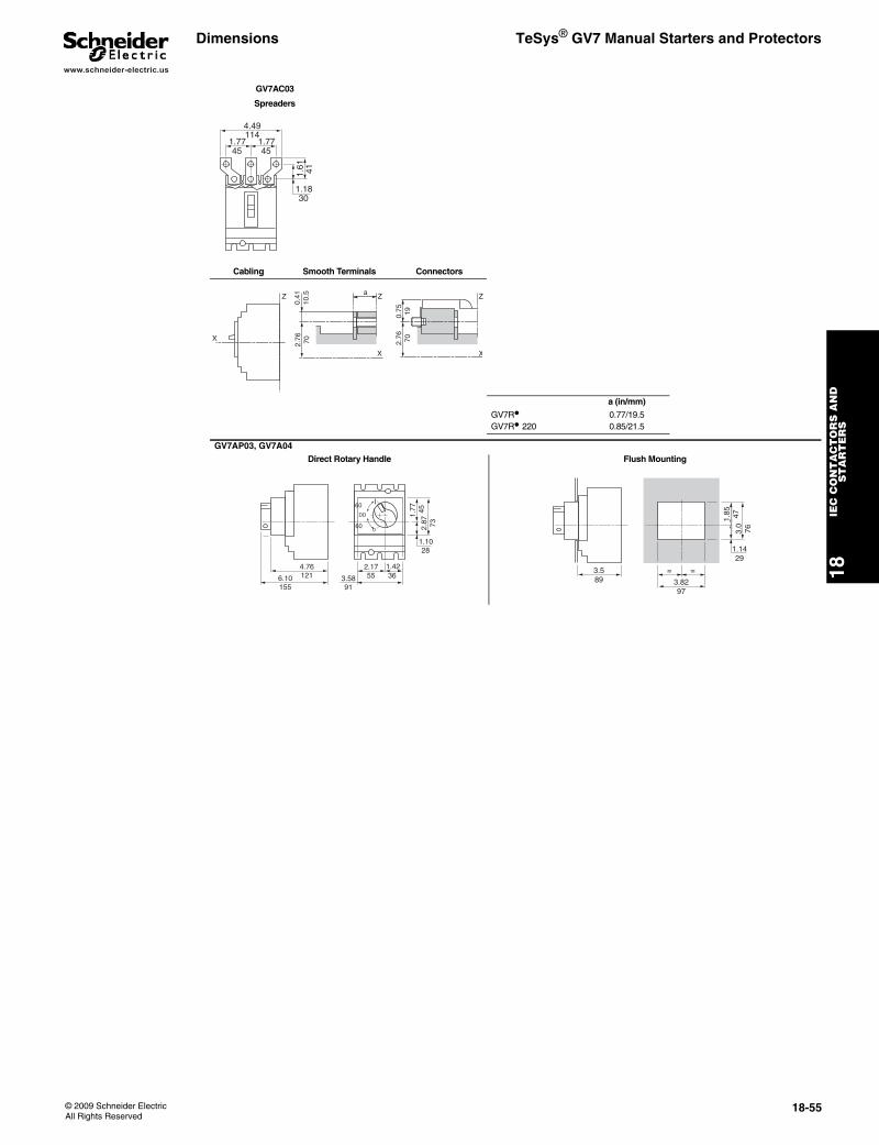
www.schneider-electric.us
18IE
C C
ON
TA
CT
OR
S A
ND
S
TA
RT
ER
S
© 2009 Schneider ElectricAll Rights Reserved
18-55
Dimensions TeSys® GV7 Manual Starters and Protectors
GV7AC03
Spreaders
Cabling Smooth Terminals Connectors
a (in/mm)
GV7R• 0.77/19.5GV7R•220 0.85/21.5
GV7AP03, GV7A04
Direct Rotary Handle Flush Mounting
1.7745
1.7745
1.1830
4.49114
1.61 41
Z
X
X
2.76 70 2.76 70
0.41
10.5 Z Z
X
0.75 19
a
2.87 73
1.77 45
6.10155
4.76121
0
I
DD
60
60
2.17553.58
91
1.4236
1.1028
= =
3.8297
1.1429
1.85 47
3.0
76
3.589
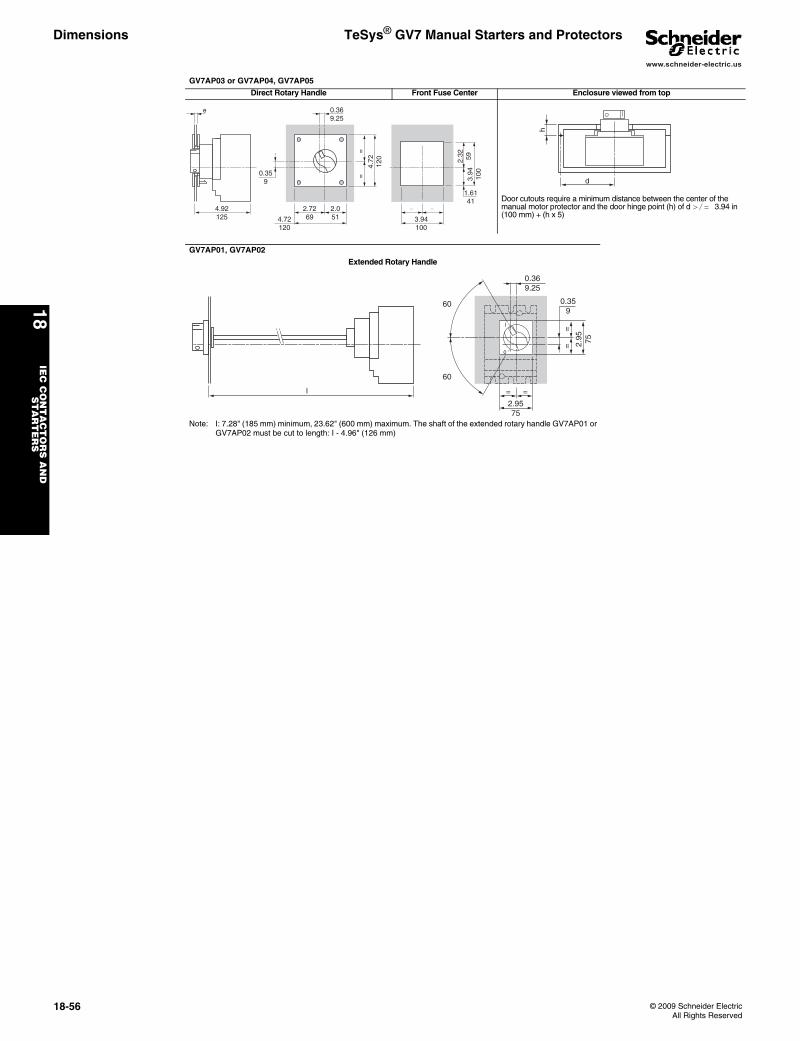
www.schneider-electric.us
18IE
C C
ON
TA
CT
OR
S A
ND
S
TA
RT
ER
S
18-56 © 2009 Schneider ElectricAll Rights Reserved
Dimensions TeSys® GV7 Manual Starters and Protectors
GV7AP03 or GV7AP04, GV7AP05
Direct Rotary Handle Front Fuse Center Enclosure viewed from top
Door cutouts require a minimum distance between the center of the manual motor protector and the door hinge point (h) of d >/= 3.94 in (100 mm) + (h x 5)
GV7AP01, GV7AP02
Extended Rotary Handle
Note: I: 7.28" (185 mm) minimum, 23.62" (600 mm) maximum. The shaft of the extended rotary handle GV7AP01 or GV7AP02 must be cut to length: I - 4.96" (126 mm)
= =
3.94100
2.32 59
3.94
100
2.7269
=
2.0514.72
120
=
4.72
120
4.92125
e 0.369.25
0.359
1.6141
h
d
2.9575
=
60
0
I
=
2.95 75
==
l
0.369.25
0.359
60