docu cutter dc-545 hc/dc-545 hcex - godar machinerygodarmachinery.com/v/dc545hc...
TRANSCRIPT
Store this manual so that it can be retrieved whenever needed.
Instruction Manual
Docu CutterDC-545 HC/DC-545 HCEX
Version. 1.0 / November 2003
Correct operation and periodic maintenance are essential for ensuring safe use of this machine.Thoroughly read this manual before using this machine.
1
2
1
○ ○ ○ ○ ○ ○ ○ ○ ○ ○ ○ ○ ○ ○ ○ ○ ○ ○ ○ ○ ○ ○ ○ ○ ○ ○ ○ ○ ○ ○ ○ ○ ○ ○ ○ ○ ○ ○ ○ ○ ○ ○ ○ ○ ○ ○ ○ ○ ○ ○ ○ ○ ○ ○ ○ ○ ○ ○ ○ ○ ○
Thank you for your purchase of the Docu Cutter DC-545 HC.To ensure safe and efficient prolonged use of this machine, read and thoroughly understand this manual beforeusing this machine. After using this manual, be sure to keep it in a place to handy reference.
PLEASE NOTEIn the interest of upgrading our products, specifications and other data given in this manual are subject tochange without notice. If the manual contains anything that you do not understand, contact the manufac-turer for clarification.
IntroductionDC-545 HC
Docu Cutter 0_1-11 03.12.8, 3:08 PM1
2
○ ○ ○ ○ ○ ○ ○ ○ ○ ○ ○ ○ ○ ○ ○ ○ ○ ○ ○ ○ ○ ○ ○ ○ ○ ○ ○ ○ ○ ○ ○ ○ ○ ○ ○ ○ ○ ○ ○ ○ ○ ○ ○ ○ ○ ○ ○ ○ ○ ○ ○ ○ ○ ○ ○ ○ ○ ○ ○ ○ ○
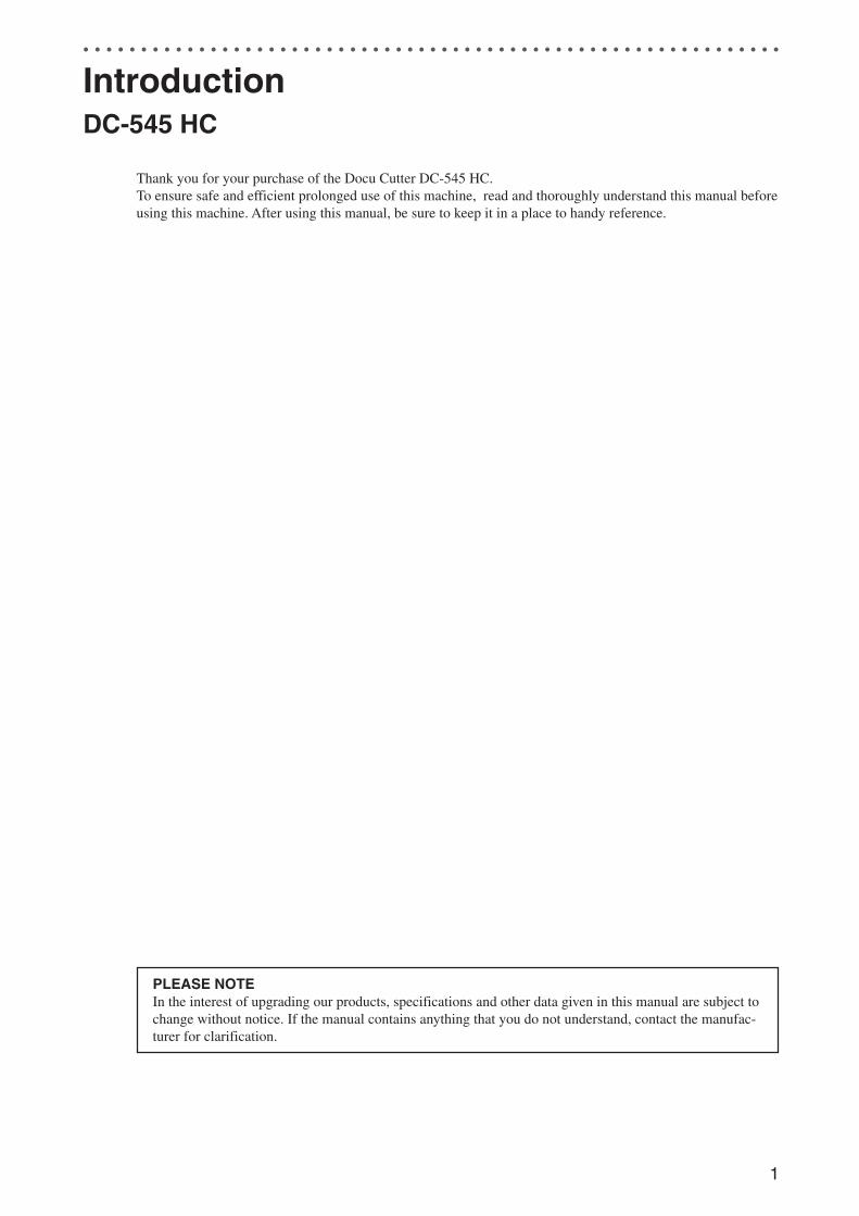
Thank you for your purchase of the Docu Cutter DC-545 HCEX.To ensure safe and efficient prolonged use of this machine, read and thoroughly understand this manual beforeusing this machine. After using this manual, be sure to keep it in a handy place to Reference.
DC-545 HCEX
PLEASE NOTEIn the interest of upgrading our products, specifications and other data given in this manual are subject tochange without notice. If the manual contains anything that you do not understand, contact the dealer forclarification.
OVERVIEW
The DC-545 HCEX was created to produce high-quality, customized products; greeting cards, postcards,brochures, business cards, and resized photographs. It does this by combining a number of devices that set upautomatically to slit, cut, and crease a sheet of paper into the desired format with no operator intervention.
Initially, the DC-545 HCEX is manually programmed with the required positions of the slits, cuts and creasesand the values are stored in a memory for future recall. A CCD sensor reads the job number encoded in abarcode on the unfinished sheet. Then, the DC-545 HCEX recalls the values from memory, sets up the slitterpositions, activates the cutter for lead, trail, and any intermediate cuts and any required creases.
In addition, when a small 90-degree angle register mark has been printed adjacent to the barcode, the positionis measured against the intended position stored in the job memory. As this mark is part of the original image,any error in its location can be compared with the stored value and used to correct the setup positions of thedevices by applying a horizontal offset to the cut and crease positions, and a vertical offset to the slit positionsto maintain precise finishing every time.
Docu Cutter 0_1-11 03.12.8, 3:08 PM2
3
2
1
○ ○ ○ ○ ○ ○ ○ ○ ○ ○ ○ ○ ○ ○ ○ ○ ○ ○ ○ ○ ○ ○ ○ ○ ○ ○ ○ ○ ○ ○ ○ ○ ○ ○ ○ ○ ○ ○ ○ ○ ○ ○ ○ ○ ○ ○ ○ ○ ○ ○ ○ ○ ○ ○ ○ ○ ○ ○ ○ ○ ○
ContentsIntroduction ......................................................................................................................... 1
DC-545 HC ................................................................................................................. 1
DC-545 HCEX ............................................................................................................ 2
Notes on Safety (Please Read and Observe) ................................................................... 5
Safety Precautions ............................................................................................... 5
Warning Sticker .......................................................................................................... 8
Positioning the Machine ............................................................................................. 9
Maintenance ............................................................................................................. 10
Conventions Used in This Manual ............................................................................ 11
Chapter 1 Operating Instraction - DC-545 HC
Part names and their functions ................................................................................. 12
Loading the paper .................................................................................................... 13
Selecting/operating/stopping a job ........................................................................... 14
Adjustments .............................................................................................................. 15
Troubleshooting table ............................................................................................... 17
Specifications ........................................................................................................... 17
Chapter 2 Before Using This Machine - DC-545 HCEX
Confirming the Packaged Materials ................................................................................ 18
How to Set up the System ............................................................................................... 19
Part Names and Their Functions .................................................................................... 21
Appearance .............................................................................................................. 21
Control Panel ............................................................................................................ 23
LCD Panel ................................................................................................................ 24
Turning Power ON/OFF .................................................................................................... 25
Turning ON the Power .............................................................................................. 25
Turning OFF the Power ............................................................................................ 25
Chapter 3 Operating Instructions - DC-545 HCEX
Automatic Cutting Using Bar Codes and Register Marks ............................................ 26
About the Waste Tray ....................................................................................................... 29
Chapter 4 Troubleshooting - DC-545 HCEX
Troubleshooting Flow Chart ............................................................................................ 30
Power Does Not Turn ON......................................................................................... 30
Cutting is Not Possible ............................................................................................. 31
Error Messages ................................................................................................................. 32
When a Paper Jam Has Occurred ................................................................................... 39
When “REJECT PAPER” is Displayed ..................................................................... 39
When “FEED JAM” is Displayed .............................................................................. 41
When “CENTER JAM” is Displayed ......................................................................... 43
Procedure of Removing Front and Rear Creaser Guides ........................................ 45
When “SLITTER JAM” is Displayed ......................................................................... 47
When “CUTTER LOCK” is Displayed ....................................................................... 49
When “CREASE LOCK” is Displayed....................................................................... 51
Docu Cutter 0_1-11 03.12.8, 3:08 PM3
4
○ ○ ○ ○ ○ ○ ○ ○ ○ ○ ○ ○ ○ ○ ○ ○ ○ ○ ○ ○ ○ ○ ○ ○ ○ ○ ○ ○ ○ ○ ○ ○ ○ ○ ○ ○ ○ ○ ○ ○ ○ ○ ○ ○ ○ ○ ○ ○ ○ ○ ○ ○ ○ ○ ○ ○ ○ ○ ○ ○ ○
Chapter 5 Manual Programming - DC-545 HCEX
Prior to Programming a Job ............................................................................................ 53
Definition of Programming Terms ................................................................................... 54
Customer Programmed Jobs .......................................................................................... 60
Factory Preset Jobs ......................................................................................................... 61
How to Manually Program a Job ..................................................................................... 64
Appendix - DC-545 HC / DC-545 HCEX
Specifications ................................................................................................................... 70
DC-545 with HC AUTO FEEDER Specifications ...................................................... 70
DC-545 with HCEX AUTO FEEDER Specifications ................................................. 71
Specifications of Reg. Mark and Bar Code .............................................................. 72
How to do AUTO CUT .............................................................................................. 82
Index .................................................................................................................................. 83
Contents
Docu Cutter 0_1-11 03.12.8, 3:08 PM4
5
2
1
○ ○ ○ ○ ○ ○ ○ ○ ○ ○ ○ ○ ○ ○ ○ ○ ○ ○ ○ ○ ○ ○ ○ ○ ○ ○ ○ ○ ○ ○ ○ ○ ○ ○ ○ ○ ○ ○ ○ ○ ○ ○ ○ ○ ○ ○ ○ ○ ○ ○ ○ ○ ○ ○ ○ ○ ○ ○ ○ ○ ○
Notes on Safety (Please Read and Observe)
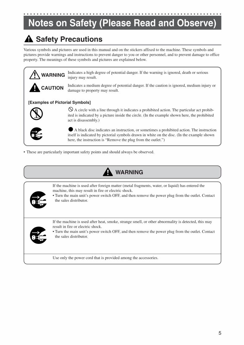
Safety PrecautionsVarious symbols and pictures are used in this manual and on the stickers affixed to the machine. These symbols andpictures provide warnings and instructions to prevent danger to you or other personnel, and to prevent damage to officeproperty. The meanings of these symbols and pictures are explained below.
WARNINGIndicates a high degree of potential danger. If the warning is ignored, death or seriousinjury may result.
CAUTION Indicates a medium degree of potential danger. If the caution is ignored, medium injury ordamage to property may result.
[Examples of Pictorial Symbols]
A circle with a line through it indicates a prohibited action. The particular act prohib-ited is indicated by a picture inside the circle. (In the example shown here, the prohibitedact is disassembly.)
A black disc indicates an instruction, or sometimes a prohibited action. The instructionitself is indicated by pictorial symbols drawn in white on the disc. (In the example shownhere, the instruction is “Remove the plug from the outlet.”)
• These are particularly important safety points and should always be observed.
WARNING
If the machine is used after foreign matter (metal fragments, water, or liquid) has entered themachine, this may result in fire or electric shock.• Turn the main unit’s power switch OFF, and then remove the power plug from the outlet. Contact
the sales distributor.
If the machine is used after heat, smoke, strange smell, or other abnormality is detected, this mayresult in fire or electric shock.• Turn the main unit’s power switch OFF, and then remove the power plug from the outlet. Contact
the sales distributor.
Use only the power cord that is provided among the accessories.
Docu Cutter 0_1-11 03.12.8, 3:08 PM5
6
○ ○ ○ ○ ○ ○ ○ ○ ○ ○ ○ ○ ○ ○ ○ ○ ○ ○ ○ ○ ○ ○ ○ ○ ○ ○ ○ ○ ○ ○ ○ ○ ○ ○ ○ ○ ○ ○ ○ ○ ○ ○ ○ ○ ○ ○ ○ ○ ○ ○ ○ ○ ○ ○ ○ ○ ○ ○ ○ ○ ○
Notes on Safety (Please Read and Observe)
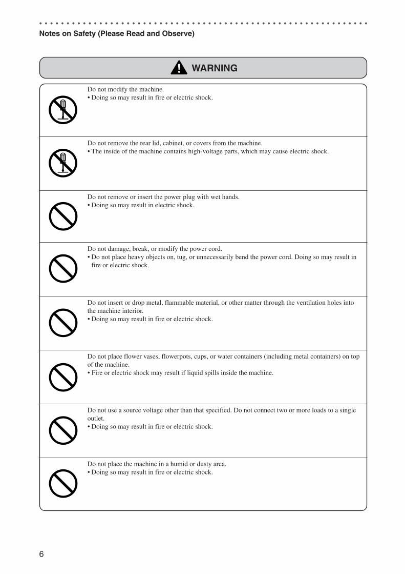
WARNING
Do not modify the machine.• Doing so may result in fire or electric shock.
Do not remove the rear lid, cabinet, or covers from the machine.• The inside of the machine contains high-voltage parts, which may cause electric shock.
Do not remove or insert the power plug with wet hands.• Doing so may result in electric shock.
Do not damage, break, or modify the power cord.• Do not place heavy objects on, tug, or unnecessarily bend the power cord. Doing so may result in
fire or electric shock.
Do not insert or drop metal, flammable material, or other matter through the ventilation holes intothe machine interior.• Doing so may result in fire or electric shock.
Do not place flower vases, flowerpots, cups, or water containers (including metal containers) on topof the machine.• Fire or electric shock may result if liquid spills inside the machine.
Do not use a source voltage other than that specified. Do not connect two or more loads to a singleoutlet.• Doing so may result in fire or electric shock.
Do not place the machine in a humid or dusty area.• Doing so may result in fire or electric shock.
Docu Cutter 0_1-11 03.12.8, 3:08 PM6
7
2
1
○ ○ ○ ○ ○ ○ ○ ○ ○ ○ ○ ○ ○ ○ ○ ○ ○ ○ ○ ○ ○ ○ ○ ○ ○ ○ ○ ○ ○ ○ ○ ○ ○ ○ ○ ○ ○ ○ ○ ○ ○ ○ ○ ○ ○ ○ ○ ○ ○ ○ ○ ○ ○ ○ ○ ○ ○ ○ ○ ○ ○
Notes on Safety (Please Read and Observe)
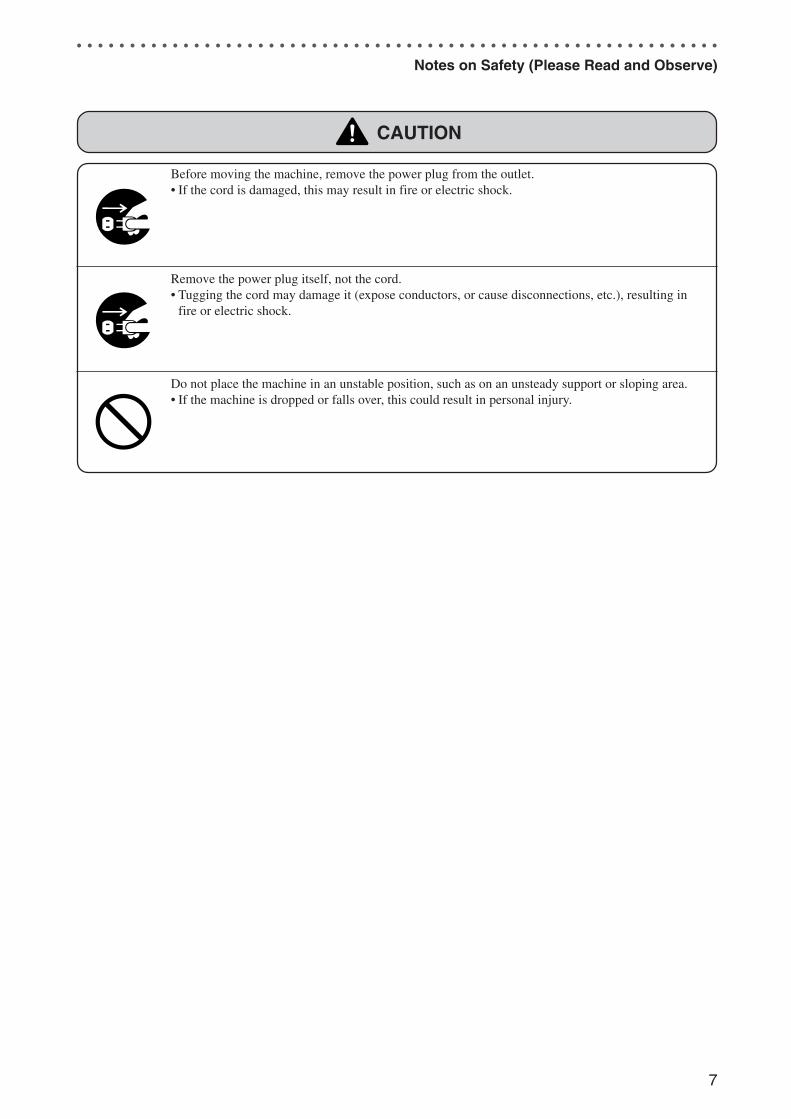
CAUTION
Before moving the machine, remove the power plug from the outlet.• If the cord is damaged, this may result in fire or electric shock.
Remove the power plug itself, not the cord.• Tugging the cord may damage it (expose conductors, or cause disconnections, etc.), resulting in
fire or electric shock.
Do not place the machine in an unstable position, such as on an unsteady support or sloping area.• If the machine is dropped or falls over, this could result in personal injury.
Docu Cutter 0_1-11 03.12.8, 3:08 PM7
8
○ ○ ○ ○ ○ ○ ○ ○ ○ ○ ○ ○ ○ ○ ○ ○ ○ ○ ○ ○ ○ ○ ○ ○ ○ ○ ○ ○ ○ ○ ○ ○ ○ ○ ○ ○ ○ ○ ○ ○ ○ ○ ○ ○ ○ ○ ○ ○ ○ ○ ○ ○ ○ ○ ○ ○ ○ ○ ○ ○ ○
Notes on Safety (Please Read and Observe)
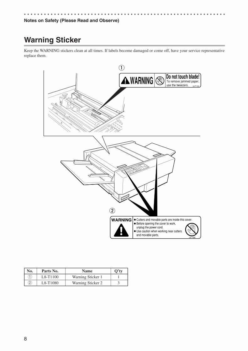
Warning StickerKeep the WARNING stickers clean at all times. If labels become damaged or come off, have your service representativereplace them.
No. Parts No. Name Q’tyq L8-T1100 Warning Sticker 1 1
w L8-T1080 Warning Sticker 2 3
WARNING Cutters and movable parts are inside this cover.Before opening the cover to work,unplug the power cord.Use caution when working near cuttersand movable parts.
L8-T1080
WARNING Do not touch blade!To remove jammed paper,use the tweezers. L8-T1100
q
w
Docu Cutter 0_1-11 03.12.8, 3:08 PM8
9
2
1
○ ○ ○ ○ ○ ○ ○ ○ ○ ○ ○ ○ ○ ○ ○ ○ ○ ○ ○ ○ ○ ○ ○ ○ ○ ○ ○ ○ ○ ○ ○ ○ ○ ○ ○ ○ ○ ○ ○ ○ ○ ○ ○ ○ ○ ○ ○ ○ ○ ○ ○ ○ ○ ○ ○ ○ ○ ○ ○ ○ ○
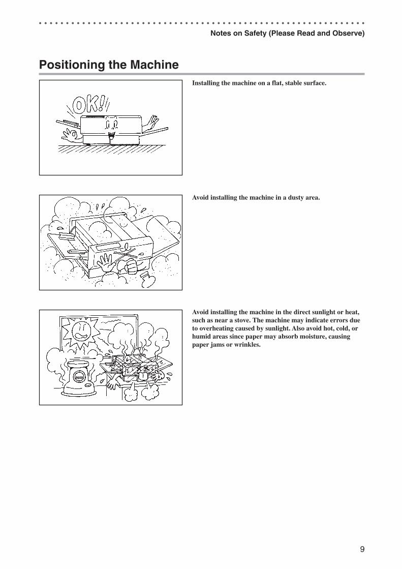
Positioning the MachineInstalling the machine on a flat, stable surface.
Avoid installing the machine in a dusty area.
Avoid installing the machine in the direct sunlight or heat,such as near a stove. The machine may indicate errors dueto overheating caused by sunlight. Also avoid hot, cold, orhumid areas since paper may absorb moisture, causingpaper jams or wrinkles.
Notes on Safety (Please Read and Observe)
Docu Cutter 0_1-11 03.12.8, 3:08 PM9
10
○ ○ ○ ○ ○ ○ ○ ○ ○ ○ ○ ○ ○ ○ ○ ○ ○ ○ ○ ○ ○ ○ ○ ○ ○ ○ ○ ○ ○ ○ ○ ○ ○ ○ ○ ○ ○ ○ ○ ○ ○ ○ ○ ○ ○ ○ ○ ○ ○ ○ ○ ○ ○ ○ ○ ○ ○ ○ ○ ○ ○
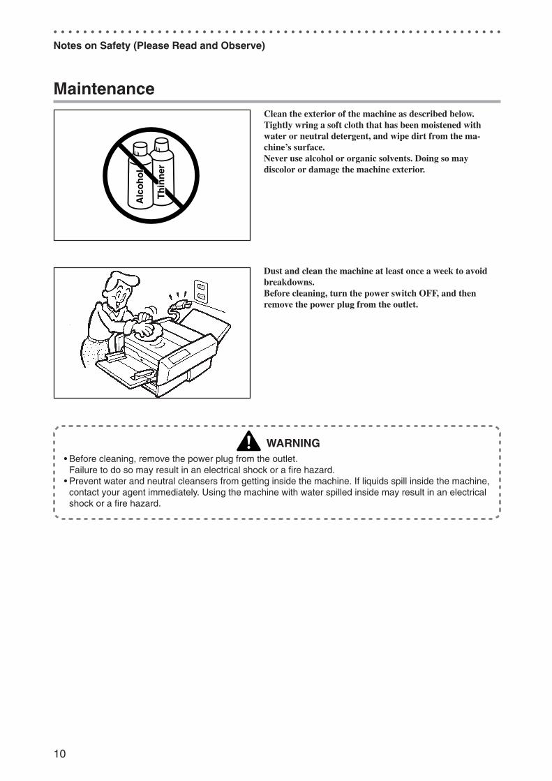
MaintenanceClean the exterior of the machine as described below.Tightly wring a soft cloth that has been moistened withwater or neutral detergent, and wipe dirt from the ma-chine’s surface.Never use alcohol or organic solvents. Doing so maydiscolor or damage the machine exterior.
Dust and clean the machine at least once a week to avoidbreakdowns.Before cleaning, turn the power switch OFF, and thenremove the power plug from the outlet.
WARNING• Before cleaning, remove the power plug from the outlet.
Failure to do so may result in an electrical shock or a fire hazard.• Prevent water and neutral cleansers from getting inside the machine. If liquids spill inside the machine,
contact your agent immediately. Using the machine with water spilled inside may result in an electricalshock or a fire hazard.
Notes on Safety (Please Read and Observe)
Docu Cutter 0_1-11 03.12.8, 3:08 PM10
11
2
1
○ ○ ○ ○ ○ ○ ○ ○ ○ ○ ○ ○ ○ ○ ○ ○ ○ ○ ○ ○ ○ ○ ○ ○ ○ ○ ○ ○ ○ ○ ○ ○ ○ ○ ○ ○ ○ ○ ○ ○ ○ ○ ○ ○ ○ ○ ○ ○ ○ ○ ○ ○ ○ ○ ○ ○ ○ ○ ○ ○ ○
Notes on Safety (Please Read and Observe)
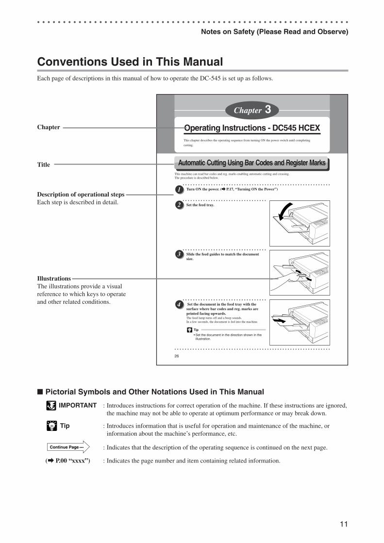
Conventions Used in This ManualEach page of descriptions in this manual of how to operate the DC-545 is set up as follows.
� Pictorial Symbols and Other Notations Used in This Manual
IMPORTANT : Introduces instructions for correct operation of the machine. If these instructions are ignored,the machine may not be able to operate at optimum performance or may break down.
Tip : Introduces information that is useful for operation and maintenance of the machine, orinformation about the machine’s performance, etc.
Continue Page ••• : Indicates that the description of the operating sequence is continued on the next page.
(a P.00 “xxxx”) : Indicates the page number and item containing related information.
Chapter
Description of operational stepsEach step is described in detail.
IllustrationsThe illustrations provide a visualreference to which keys to operateand other related conditions.
Title
Docu Cutter 0_1-11 03.12.8, 3:08 PM11
12
e
r
q
wt
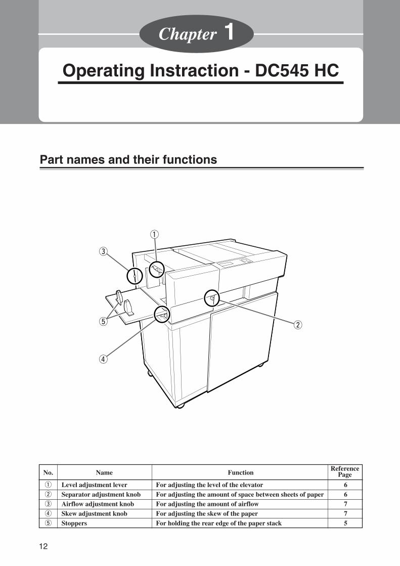
No. Name Function
q Level adjustment lever For adjusting the level of the elevator 6w Separator adjustment knob For adjusting the amount of space between sheets of paper 6e Airflow adjustment knob For adjusting the amount of airflow 7r Skew adjustment knob For adjusting the skew of the paper 7t Stoppers For holding the rear edge of the paper stack 5
ReferencePage
Operating Instraction - DC545 HC
Chapter 1
Part names and their functions
Docu Cutter(HC) 1_12-17 03.12.8, 3:08 PM12
13
3
2
11
Operating Instraction - D
C545 H
C
Loading the paper
○ ○ ○ ○ ○ ○ ○ ○ ○ ○ ○ ○ ○ ○ ○ ○ ○ ○ ○ ○ ○ ○ ○ ○ ○ ○ ○ ○ ○ ○ ○ ○ ○
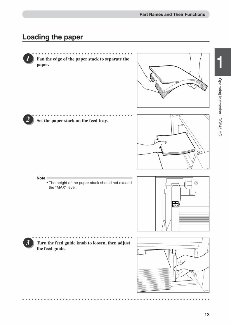
Fan the edge of the paper stack to separate thepaper.
○ ○ ○ ○ ○ ○ ○ ○ ○ ○ ○ ○ ○ ○ ○ ○ ○ ○ ○ ○ ○ ○ ○ ○ ○ ○ ○ ○ ○ ○ ○ ○ ○
Set the paper stack on the feed tray.
Note• The height of the paper stack should not exceed
the "MAX" level.
○ ○ ○ ○ ○ ○ ○ ○ ○ ○ ○ ○ ○ ○ ○ ○ ○ ○ ○ ○ ○ ○ ○ ○ ○ ○ ○ ○ ○ ○ ○ ○ ○
Turn the feed guide knob to loosen, then adjustthe feed guide.
○ ○ ○ ○ ○ ○ ○ ○ ○ ○ ○ ○ ○ ○ ○ ○ ○ ○ ○ ○ ○ ○ ○ ○ ○ ○ ○ ○ ○ ○ ○ ○ ○ ○ ○ ○ ○ ○ ○ ○ ○ ○ ○ ○ ○ ○ ○ ○ ○ ○ ○ ○ ○ ○ ○ ○ ○ ○ ○ ○ ○
MAX
Part Names and Their Functions
Docu Cutter(HC) 1_12-17 03.12.8, 3:08 PM13
14
○ ○ ○ ○ ○ ○ ○ ○ ○ ○ ○ ○ ○ ○ ○ ○ ○ ○ ○ ○ ○ ○ ○ ○ ○ ○ ○ ○ ○ ○ ○ ○ ○
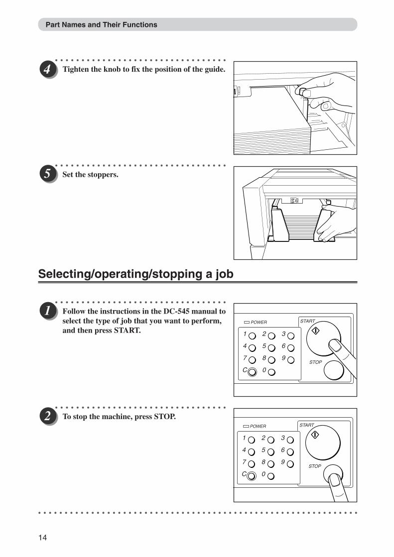
Tighten the knob to fix the position of the guide.
○ ○ ○ ○ ○ ○ ○ ○ ○ ○ ○ ○ ○ ○ ○ ○ ○ ○ ○ ○ ○ ○ ○ ○ ○ ○ ○ ○ ○ ○ ○ ○ ○
Set the stoppers.
Selecting/operating/stopping a job
○ ○ ○ ○ ○ ○ ○ ○ ○ ○ ○ ○ ○ ○ ○ ○ ○ ○ ○ ○ ○ ○ ○ ○ ○ ○ ○ ○ ○ ○ ○ ○ ○
Follow the instructions in the DC-545 manual toselect the type of job that you want to perform,and then press START.
○ ○ ○ ○ ○ ○ ○ ○ ○ ○ ○ ○ ○ ○ ○ ○ ○ ○ ○ ○ ○ ○ ○ ○ ○ ○ ○ ○ ○ ○ ○ ○ ○
To stop the machine, press STOP.
○ ○ ○ ○ ○ ○ ○ ○ ○ ○ ○ ○ ○ ○ ○ ○ ○ ○ ○ ○ ○ ○ ○ ○ ○ ○ ○ ○ ○ ○ ○ ○ ○ ○ ○ ○ ○ ○ ○ ○ ○ ○ ○ ○ ○ ○ ○ ○ ○ ○ ○ ○ ○ ○ ○ ○ ○ ○ ○ ○ ○
1
4
7
C
2
5
8
0
3
6
9
POWER START
STOP
1
4
7
C
2
5
8
0
3
6
9
POWER START
STOP
Part Names and Their Functions
Docu Cutter(HC) 1_12-17 03.12.8, 3:08 PM14
15
3
2
11
Operating Instraction - D
C545 H
C
Adjustments○ ○ ○ ○ ○ ○ ○ ○ ○ ○ ○ ○ ○ ○ ○ ○ ○ ○ ○ ○ ○ ○ ○ ○ ○ ○ ○ ○ ○ ○ ○ ○ ○
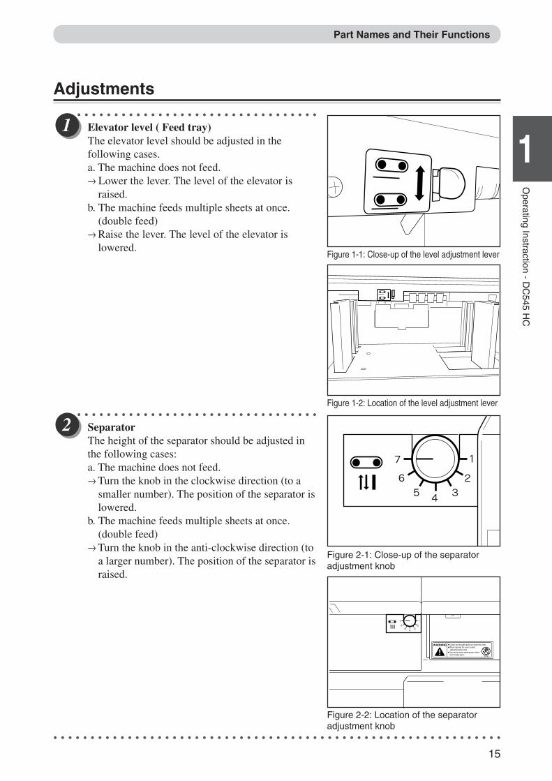
Elevator level ( Feed tray)The elevator level should be adjusted in thefollowing cases.a. The machine does not feed.→ Lower the lever. The level of the elevator is
raised.b. The machine feeds multiple sheets at once.
(double feed)→ Raise the lever. The level of the elevator is
lowered.
○ ○ ○ ○ ○ ○ ○ ○ ○ ○ ○ ○ ○ ○ ○ ○ ○ ○ ○ ○ ○ ○ ○ ○ ○ ○ ○ ○ ○ ○ ○ ○ ○
SeparatorThe height of the separator should be adjusted inthe following cases:a. The machine does not feed.→ Turn the knob in the clockwise direction (to a
smaller number). The position of the separator islowered.
b. The machine feeds multiple sheets at once.(double feed)
→ Turn the knob in the anti-clockwise direction (toa larger number). The position of the separator israised.
○ ○ ○ ○ ○ ○ ○ ○ ○ ○ ○ ○ ○ ○ ○ ○ ○ ○ ○ ○ ○ ○ ○ ○ ○ ○ ○ ○ ○ ○ ○ ○ ○ ○ ○ ○ ○ ○ ○ ○ ○ ○ ○ ○ ○ ○ ○ ○ ○ ○ ○ ○ ○ ○ ○ ○ ○ ○ ○ ○ ○
Figure 1-1: Close-up of the level adjustment lever
Figure 1-2: Location of the level adjustment lever
Figure 2-1: Close-up of the separatoradjustment knob
WARNING Cutters and movable parts are inside this cover.Before opening the cover to work,unplug the power cord.Use caution when working near cuttersand movable parts.
L8-T1080
Figure 2-2: Location of the separatoradjustment knob
Part Names and Their Functions
Docu Cutter(HC) 1_12-17 03.12.8, 3:08 PM15
16
○ ○ ○ ○ ○ ○ ○ ○ ○ ○ ○ ○ ○ ○ ○ ○ ○ ○ ○ ○ ○ ○ ○ ○ ○ ○ ○ ○ ○ ○ ○ ○ ○
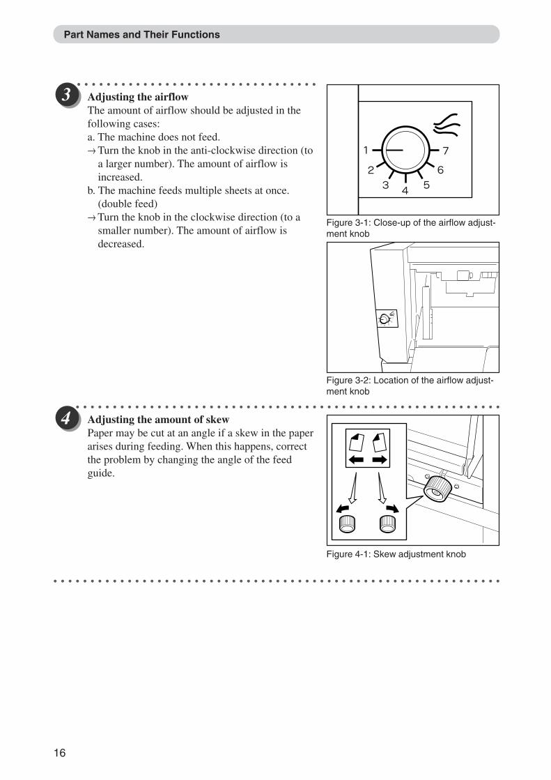
Adjusting the airflowThe amount of airflow should be adjusted in thefollowing cases:a. The machine does not feed.→ Turn the knob in the anti-clockwise direction (to
a larger number). The amount of airflow isincreased.
b. The machine feeds multiple sheets at once.(double feed)
→ Turn the knob in the clockwise direction (to asmaller number). The amount of airflow isdecreased.
○ ○ ○ ○ ○ ○ ○ ○ ○ ○ ○ ○ ○ ○ ○ ○ ○ ○ ○ ○ ○ ○ ○ ○ ○ ○ ○ ○ ○ ○ ○ ○ ○ ○ ○ ○ ○ ○ ○ ○ ○ ○ ○ ○ ○ ○ ○ ○ ○ ○ ○ ○ ○ ○ ○ ○ ○ ○ ○ ○ ○
Adjusting the amount of skewPaper may be cut at an angle if a skew in the paperarises during feeding. When this happens, correctthe problem by changing the angle of the feedguide.
○ ○ ○ ○ ○ ○ ○ ○ ○ ○ ○ ○ ○ ○ ○ ○ ○ ○ ○ ○ ○ ○ ○ ○ ○ ○ ○ ○ ○ ○ ○ ○ ○ ○ ○ ○ ○ ○ ○ ○ ○ ○ ○ ○ ○ ○ ○ ○ ○ ○ ○ ○ ○ ○ ○ ○ ○ ○ ○ ○ ○
Figure 3-1: Close-up of the airflow adjust-ment knob
Figure 3-2: Location of the airflow adjust-ment knob
Figure 4-1: Skew adjustment knob
Part Names and Their Functions
Docu Cutter(HC) 1_12-17 03.12.8, 3:08 PM16
17
3
2
11
Operating Instraction - D
C545 H
C
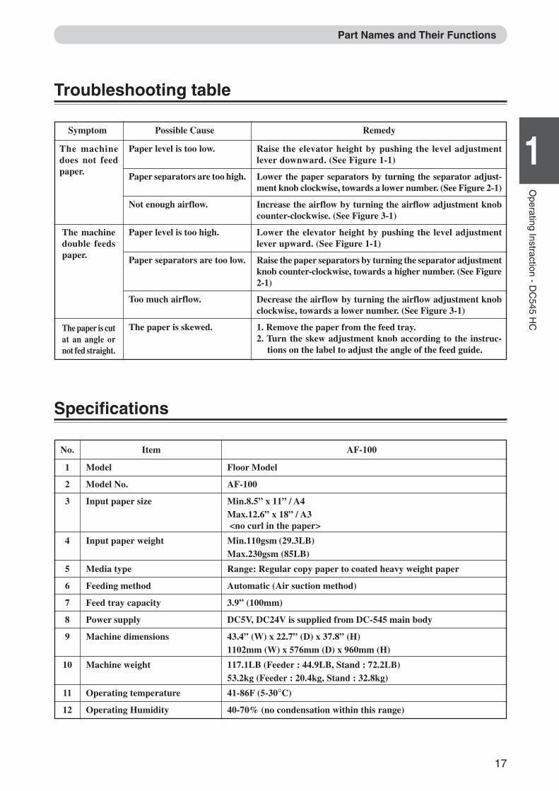
No. Item AF-100
1 Model Floor Model
2 Model No. AF-100
3 Input paper size Min.8.5” x 11” / A4Max.12.6” x 18” / A3 <no curl in the paper>
4 Input paper weight Min.110gsm (29.3LB)Max.230gsm (85LB)
5 Media type Range: Regular copy paper to coated heavy weight paper
6 Feeding method Automatic (Air suction method)
7 Feed tray capacity 3.9” (100mm)
8 Power supply DC5V, DC24V is supplied from DC-545 main body
9 Machine dimensions 43.4” (W) x 22.7” (D) x 37.8” (H)1102mm (W) x 576mm (D) x 960mm (H)
10 Machine weight 117.1LB (Feeder : 44.9LB, Stand : 72.2LB)53.2kg (Feeder : 20.4kg, Stand : 32.8kg)
11 Operating temperature 41-86F (5-30°C)
12 Operating Humidity 40-70% (no condensation within this range)
Troubleshooting table
Raise the elevator height by pushing the level adjustmentlever downward. (See Figure 1-1)
Lower the paper separators by turning the separator adjust-ment knob clockwise, towards a lower number. (See Figure 2-1)
Increase the airflow by turning the airflow adjustment knobcounter-clockwise. (See Figure 3-1)
Lower the elevator height by pushing the level adjustmentlever upward. (See Figure 1-1)
Raise the paper separators by turning the separator adjustmentknob counter-clockwise, towards a higher number. (See Figure2-1)
Decrease the airflow by turning the airflow adjustment knobclockwise, towards a lower number. (See Figure 3-1)
1. Remove the paper from the feed tray.2. Turn the skew adjustment knob according to the instruc-
tions on the label to adjust the angle of the feed guide.
The machinedoes not feedpaper.
The machinedouble feedspaper.
The paper is cutat an angle ornot fed straight.
Symptom Possible Cause Remedy
Paper level is too low.
Paper separators are too high.
Not enough airflow.
Paper level is too high.
Paper separators are too low.
Too much airflow.
The paper is skewed.
Specifications
Part Names and Their Functions
Docu Cutter(HC) 1_12-17 03.12.8, 3:09 PM17
18
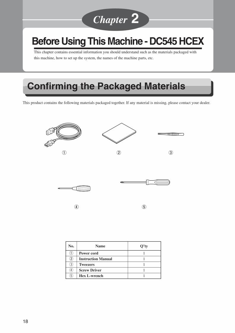
No. Name Q’ty
q Power cord 1
w Instruction Manual 1
e Tweezers 1
r Screw Driver 1
t Hex L-wrench 1
Before Using This Machine - DC545 HCEXThis chapter contains essential information you should understand such as the materials packaged with
this machine, how to set up the system, the names of the machine parts, etc.
Chapter 2
This product contains the following materials packaged together. If any material is missing, please contact your dealer.
Confirming the Packaged Materials
q w e
r t
Docu Cutter(HCEX) 2_18-25 03.12.8, 3:09 PM18
19
3
2
1
Before U
sing This M
achine - DC
545 HC
EX
2
How to Set up the System
This section describes the cautions and the procedure when you set up this machine.
○ ○ ○ ○ ○ ○ ○ ○ ○ ○ ○ ○ ○ ○ ○ ○ ○ ○ ○ ○ ○ ○ ○ ○ ○ ○ ○ ○ ○ ○ ○ ○ ○ ○ ○ ○ ○ ○ ○ ○ ○ ○ ○ ○ ○ ○ ○ ○ ○ ○ ○ ○ ○ ○ ○ ○ ○ ○
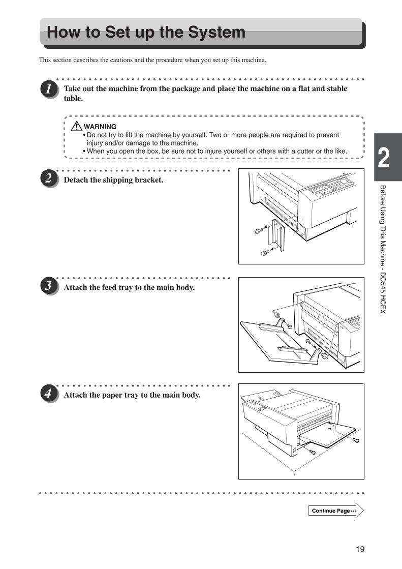
Take out the machine from the package and place the machine on a flat and stabletable.
WARNING• Do not try to lift the machine by yourself. Two or more people are required to prevent
injury and/or damage to the machine.• When you open the box, be sure not to injure yourself or others with a cutter or the like.
○ ○ ○ ○ ○ ○ ○ ○ ○ ○ ○ ○ ○ ○ ○ ○ ○ ○ ○ ○ ○ ○ ○ ○ ○ ○ ○ ○ ○ ○ ○ ○ ○
Detach the shipping bracket.
○ ○ ○ ○ ○ ○ ○ ○ ○ ○ ○ ○ ○ ○ ○ ○ ○ ○ ○ ○ ○ ○ ○ ○ ○ ○ ○ ○ ○ ○ ○ ○ ○
Attach the feed tray to the main body.
○ ○ ○ ○ ○ ○ ○ ○ ○ ○ ○ ○ ○ ○ ○ ○ ○ ○ ○ ○ ○ ○ ○ ○ ○ ○ ○ ○ ○ ○ ○ ○ ○
Attach the paper tray to the main body.
○ ○ ○ ○ ○ ○ ○ ○ ○ ○ ○ ○ ○ ○ ○ ○ ○ ○ ○ ○ ○ ○ ○ ○ ○ ○ ○ ○ ○ ○ ○ ○ ○ ○ ○ ○ ○ ○ ○ ○ ○ ○ ○ ○ ○ ○ ○ ○ ○ ○ ○ ○ ○ ○ ○ ○ ○ ○ ○ ○ ○
Continue Page •••
Docu Cutter(HCEX) 2_18-25 03.12.8, 3:09 PM19
20
○ ○ ○ ○ ○ ○ ○ ○ ○ ○ ○ ○ ○ ○ ○ ○ ○ ○ ○ ○ ○ ○ ○ ○ ○ ○ ○ ○ ○ ○ ○ ○ ○
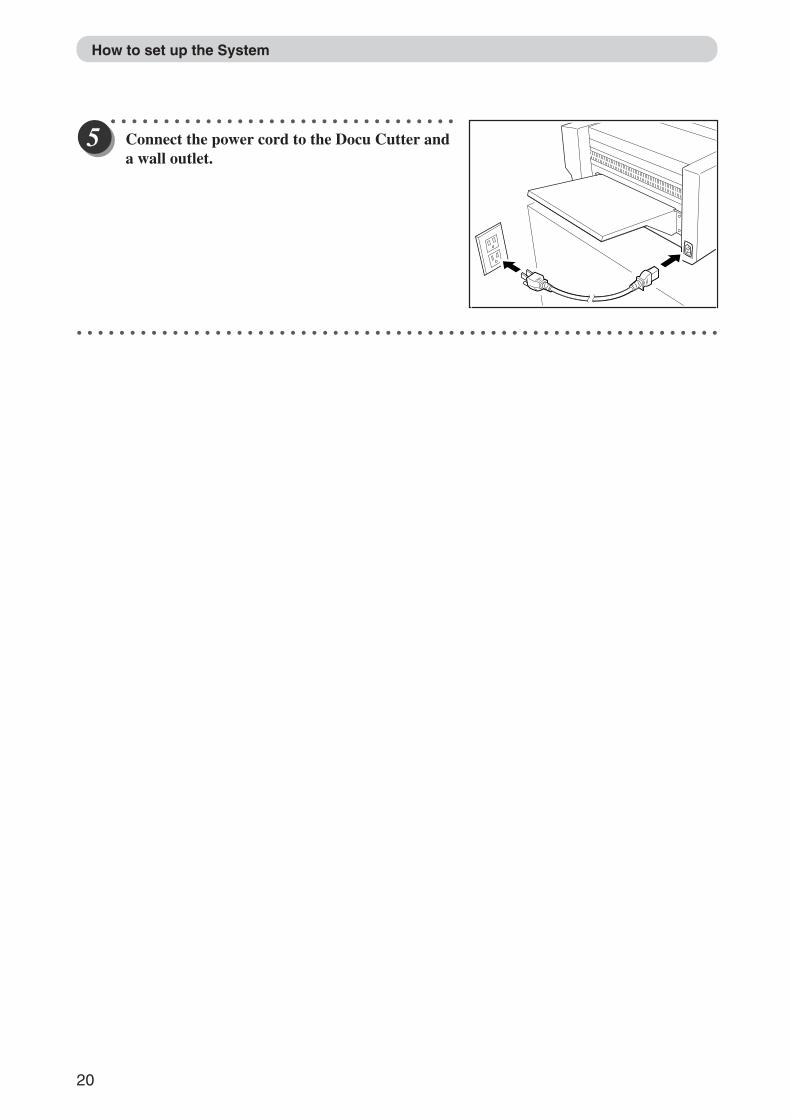
Connect the power cord to the Docu Cutter anda wall outlet.
○ ○ ○ ○ ○ ○ ○ ○ ○ ○ ○ ○ ○ ○ ○ ○ ○ ○ ○ ○ ○ ○ ○ ○ ○ ○ ○ ○ ○ ○ ○ ○ ○ ○ ○ ○ ○ ○ ○ ○ ○ ○ ○ ○ ○ ○ ○ ○ ○ ○ ○ ○ ○ ○ ○ ○ ○ ○ ○ ○ ○
How to set up the System
Docu Cutter(HCEX) 2_18-25 03.12.8, 3:09 PM20
21
3
2
1
Before U
sing This M
achine - DC
545 HC
EX
2
Part Names and Their Functions
Appearance
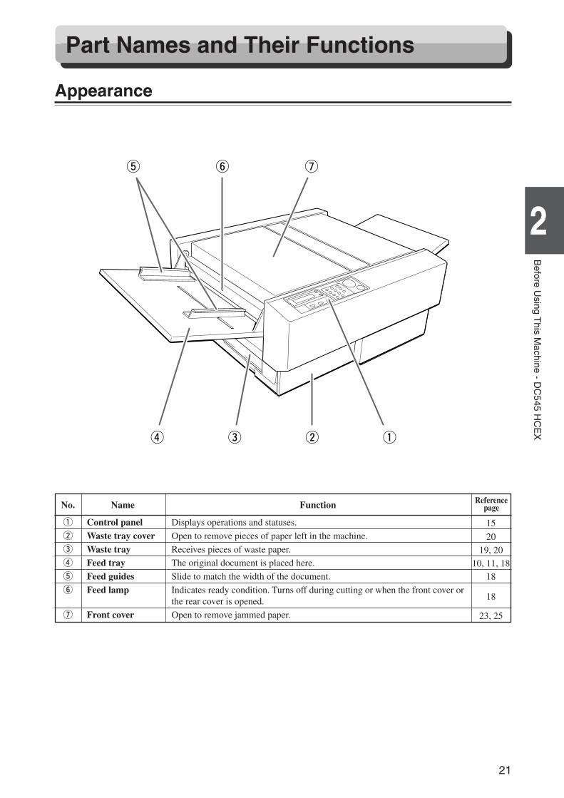
No. Name Function
q Control panel Displays operations and statuses.
w Waste tray cover Open to remove pieces of paper left in the machine.
e Waste tray Receives pieces of waste paper.
r Feed tray The original document is placed here.
t Feed guides Slide to match the width of the document.
y Feed lamp Indicates ready condition. Turns off during cutting or when the front cover orthe rear cover is opened.
u Front cover Open to remove jammed paper.
Referencepage
qwer
uyt
15
20
19, 20
10, 11, 1818
18
23, 25
Docu Cutter(HCEX) 2_18-25 03.12.8, 3:09 PM21
22
ReferencepageNo. Name Function
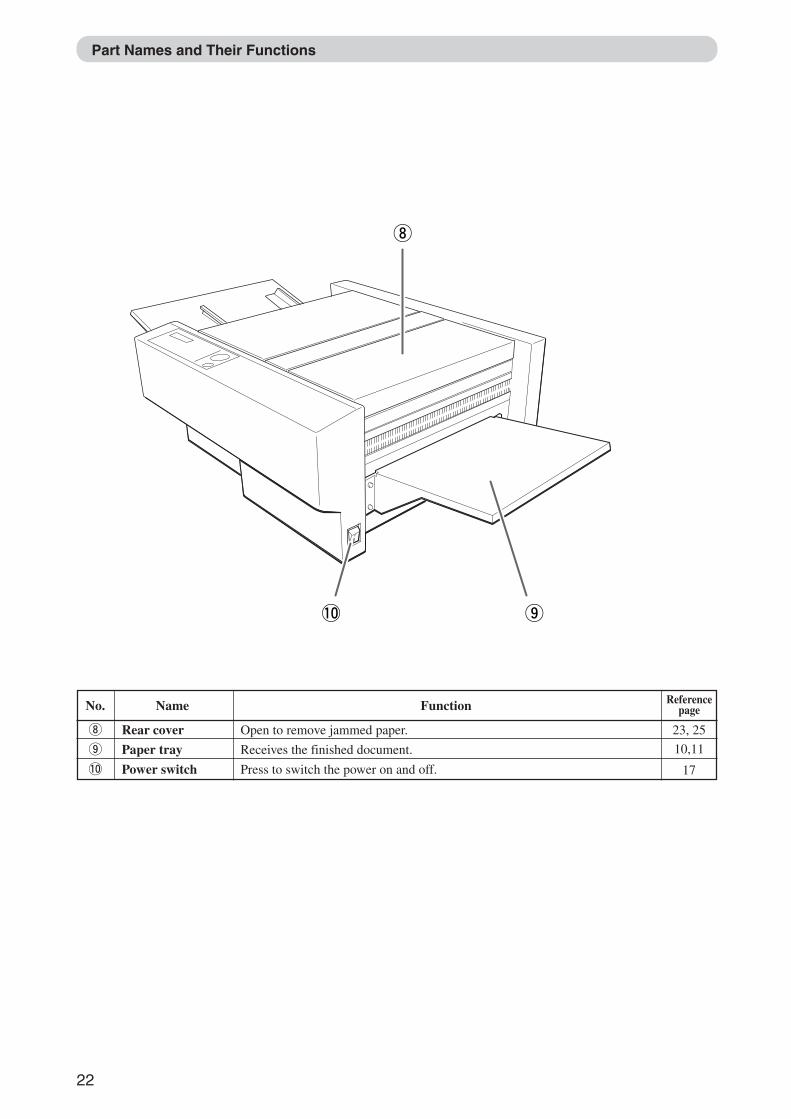
i Rear cover Open to remove jammed paper.
o Paper tray Receives the finished document.
!0 Power switch Press to switch the power on and off.
Part Names and Their Functions
23, 25
10,11
17
o!0
i
Docu Cutter(HCEX) 2_18-25 03.12.8, 3:09 PM22
23
3
2
1
Before U
sing This M
achine - DC
545 HC
EX
2
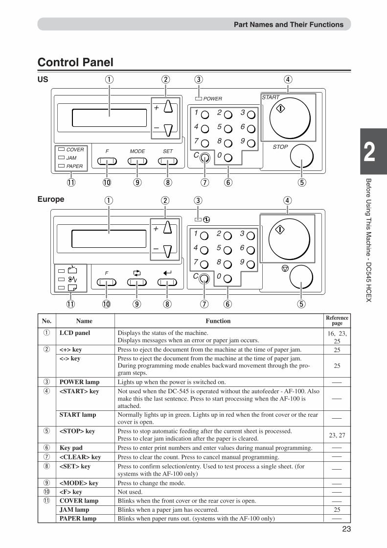
No. Name Function
q LCD panel Displays the status of the machine.Displays messages when an error or paper jam occurs.
w <+> key Press to eject the document from the machine at the time of paper jam.<-> key Press to eject the document from the machine at the time of paper jam.
During programming mode enables backward movement through the pro-gram steps.
e POWER lamp Lights up when the power is switched on.
r <START> key Not used when the DC-545 is operated without the autofeeder - AF-100. Alsomake this the last sentence. Press to start processing when the AF-100 isattached.
START lamp Normally lights up in green. Lights up in red when the front cover or the rearcover is open.
t <STOP> key Press to stop automatic feeding after the current sheet is processed.Press to clear jam indication after the paper is cleared.
y Key pad Press to enter print numbers and enter values during manual programming.
u <CLEAR> key Press to clear the count. Press to cancel manual programming.
i <SET> key Press to confirm selection/entry. Used to test process a single sheet. (forsystems with the AF-100 only)
o <MODE> key Press to change the mode.!0 <F> key Not used.!1 COVER lamp Blinks when the front cover or the rear cover is open.
JAM lamp Blinks when a paper jam has occurred.PAPER lamp Blinks when paper runs out. (systems with the AF-100 only)
Part Names and Their Functions
Referencepage
16, 23,2525
25
23, 27
25
Control PanelUS
COVER
JAMF
PAPER
MODE SET
+
–
1
4
7
C
2
5
8
0
3
6
9
POWER START
STOP
!0!1 o i u ty
w e rq
Europe
F
+
–
1
4
7
C
2
5
8
0
3
6
9
!0!1 o i u ty
w e rq
Docu Cutter(HCEX) 2_18-25 03.12.8, 3:09 PM23
24
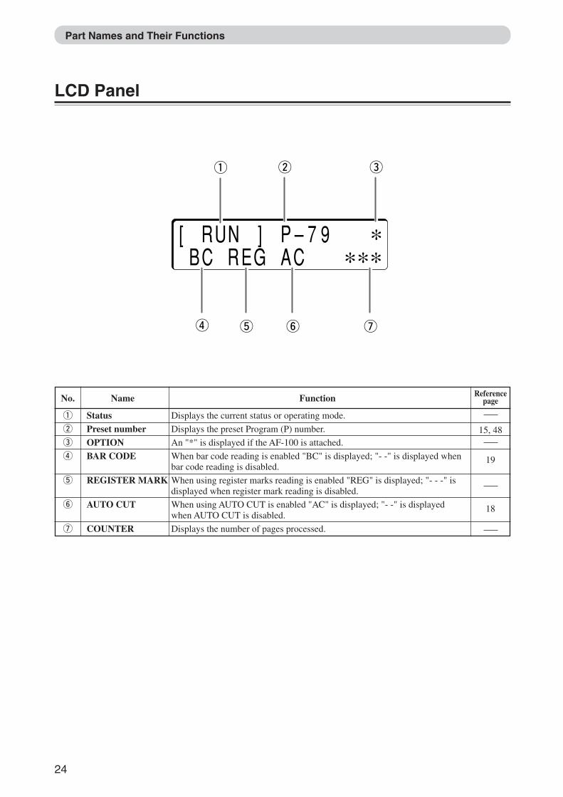
No. Name Function
q Status Displays the current status or operating mode.
w Preset number Displays the preset Program (P) number.
e OPTION An "*" is displayed if the AF-100 is attached.
r BAR CODE When bar code reading is enabled "BC" is displayed; "- -" is displayed whenbar code reading is disabled.
t REGISTER MARK When using register marks reading is enabled "REG" is displayed; "- - -" isdisplayed when register mark reading is disabled.
y AUTO CUT When using AUTO CUT is enabled "AC" is displayed; "- -" is displayedwhen AUTO CUT is disabled.
u COUNTER Displays the number of pages processed.
15, 48
19
18
Part Names and Their Functions
Referencepage
LCD Panel
yt u
w eq
r
[ RUN ] P–79 ∗ BC REG AC ∗ ∗ ∗
Docu Cutter(HCEX) 2_18-25 03.12.8, 3:09 PM24
25
3
2
1
Before U
sing This M
achine - DC
545 HC
EX
2
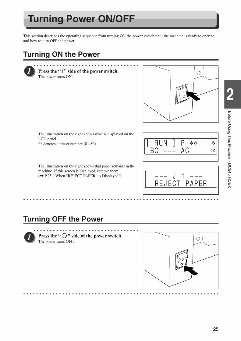
This section describes the operating sequence from turning ON the power switch until the machine is ready to operate,and how to turn OFF the power.
Turning ON the Power○ ○ ○ ○ ○ ○ ○ ○ ○ ○ ○ ○ ○ ○ ○ ○ ○ ○ ○ ○ ○ ○ ○ ○ ○ ○ ○ ○ ○ ○ ○ ○ ○
Press the “ | ” side of the power switch.The power turns ON.
The illustration on the right shows what is displayed on theLCD panel.** denotes a preset number (01-80).
The illustration on the right shows that paper remains in themachine. If this screen is displayed, remove them.(a P.25, “When “REJECT PAPER” is Displayed”)
○ ○ ○ ○ ○ ○ ○ ○ ○ ○ ○ ○ ○ ○ ○ ○ ○ ○ ○ ○ ○ ○ ○ ○ ○ ○ ○ ○ ○ ○ ○ ○ ○ ○ ○ ○ ○ ○ ○ ○ ○ ○ ○ ○ ○ ○ ○ ○ ○ ○ ○ ○ ○ ○ ○ ○ ○ ○ ○ ○ ○
Turning OFF the Power○ ○ ○ ○ ○ ○ ○ ○ ○ ○ ○ ○ ○ ○ ○ ○ ○ ○ ○ ○ ○ ○ ○ ○ ○ ○ ○ ○ ○ ○ ○ ○ ○
Press the “ KKKKK ” side of the power switch.The power turns OFF.
○ ○ ○ ○ ○ ○ ○ ○ ○ ○ ○ ○ ○ ○ ○ ○ ○ ○ ○ ○ ○ ○ ○ ○ ○ ○ ○ ○ ○ ○ ○ ○ ○ ○ ○ ○ ○ ○ ○ ○ ○ ○ ○ ○ ○ ○ ○ ○ ○ ○ ○ ○ ○ ○ ○ ○ ○ ○ ○ ○ ○
Turning Power ON/OFF
[ RUN ] P-∗∗ ∗ BC ––– AC ∗
––– J 1 ––– REJECT PAPER
Docu Cutter(HCEX) 2_18-25 03.12.8, 3:09 PM25
26
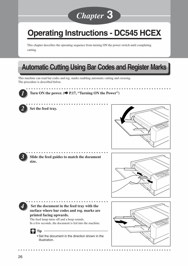
Automatic Cutting Using Bar Codes and Register MarksThis machine can read bar codes and reg. marks enabling automatic cutting and creasing.The procedure is described below.
○ ○ ○ ○ ○ ○ ○ ○ ○ ○ ○ ○ ○ ○ ○ ○ ○ ○ ○ ○ ○ ○ ○ ○ ○ ○ ○ ○ ○ ○ ○ ○ ○ ○ ○ ○ ○ ○ ○ ○ ○ ○ ○ ○ ○ ○ ○ ○ ○ ○ ○ ○ ○ ○ ○ ○ ○ ○
Turn ON the power. (aaaaa P.17, “Turning ON the Power”)
○ ○ ○ ○ ○ ○ ○ ○ ○ ○ ○ ○ ○ ○ ○ ○ ○ ○ ○ ○ ○ ○ ○ ○ ○ ○ ○ ○ ○ ○ ○ ○ ○
Set the feed tray.
○ ○ ○ ○ ○ ○ ○ ○ ○ ○ ○ ○ ○ ○ ○ ○ ○ ○ ○ ○ ○ ○ ○ ○ ○ ○ ○ ○ ○ ○ ○ ○ ○
Slide the feed guides to match the documentsize.
○ ○ ○ ○ ○ ○ ○ ○ ○ ○ ○ ○ ○ ○ ○ ○ ○ ○ ○ ○ ○ ○ ○ ○ ○ ○ ○ ○ ○ ○ ○ ○ ○
Set the document in the feed tray with thesurface where bar codes and reg. marks areprinted facing upwards.The feed lamp turns off and a beep sounds.In a few seconds, the document is fed into the machine.
Tip
• Set the document in the direction shown in theillustration.
○ ○ ○ ○ ○ ○ ○ ○ ○ ○ ○ ○ ○ ○ ○ ○ ○ ○ ○ ○ ○ ○ ○ ○ ○ ○ ○ ○ ○ ○ ○ ○ ○ ○ ○ ○ ○ ○ ○ ○ ○ ○ ○ ○ ○ ○ ○ ○ ○ ○ ○ ○ ○ ○ ○ ○ ○ ○ ○ ○ ○
Operating Instructions - DC545 HCEXThis chapter describes the operating sequence from turning ON the power switch until completing
cutting.
Chapter 3
Docu Cutter(HCEX) 3_26-29 03.12.8, 3:09 PM26
27
2
1
3
Operating Instructions - D
C545 H
CE
XAutomatic Cutting Using Bar Codes and Register Marks
○ ○ ○ ○ ○ ○ ○ ○ ○ ○ ○ ○ ○ ○ ○ ○ ○ ○ ○ ○ ○ ○ ○ ○ ○ ○ ○ ○ ○ ○ ○ ○ ○ ○ ○ ○ ○ ○ ○ ○ ○ ○ ○ ○ ○ ○ ○ ○ ○ ○ ○ ○ ○ ○ ○ ○ ○ ○
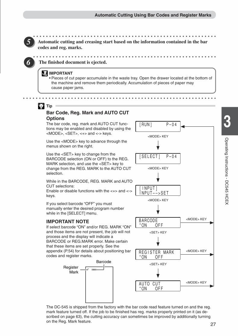
Automatic cutting and creasing start based on the information contained in the barcodes and reg. marks.
○ ○ ○ ○ ○ ○ ○ ○ ○ ○ ○ ○ ○ ○ ○ ○ ○ ○ ○ ○ ○ ○ ○ ○ ○ ○ ○ ○ ○ ○ ○ ○ ○ ○ ○ ○ ○ ○ ○ ○ ○ ○ ○ ○ ○ ○ ○ ○ ○ ○ ○ ○ ○ ○ ○ ○ ○ ○
The finished document is ejected.
IMPORTANT• Pieces of cut paper accumulate in the waste tray. Open the drawer located at the bottom of
the machine and remove them periodically. Accumulation of pieces of paper maycause paper jams.
○ ○ ○ ○ ○ ○ ○ ○ ○ ○ ○ ○ ○ ○ ○ ○ ○ ○ ○ ○ ○ ○ ○ ○ ○ ○ ○ ○ ○ ○ ○ ○ ○ ○ ○ ○ ○ ○ ○ ○ ○ ○ ○ ○ ○ ○ ○ ○ ○ ○ ○ ○ ○ ○ ○ ○ ○ ○ ○ ○ ○
Tip
Bar Code, Reg. Mark and AUTO CUTOptionsThe bar code, reg. mark and AUTO CUT func-tions may be enabled and disabled by using the<MODE>, <SET>, <+> and <-> keys.
Use the <MODE> key to advance through themenus shown on the right.
Use the <SET> key to change from theBARCODE selection (ON or OFF) to the REG.MARK selection, and use the <SET> key tochange from the REG. MARK to the AUTO CUTselection.
While in the BARCODE, REG. MARK and AUTOCUT selections:Enable or disable functions with the <+> and <->keys.
If you select barcode “OFF” you mustmanually enter the desired program numberwhile in the [SELECT] menu.
IMPORTANT NOTEIf select barcode “ON” and/or REG. MARK “ON”and those items are not present, the job will notprocess and the display will indicate aBARCODE or REG.MARK error. Make certainthat these items are set properly. See theappendix (P.54) for details about positioning barcodes and register marks.
[RUN] P–04
<MODE> KEY
[SELECT] P–04
<MODE> KEY
[INPUT] INPUT––>SET
<MODE> KEY
BARCODE *ON OFF
<SET> KEY
<MODE> KEY
<MODE> KEY
REGISTER MARK *ON OFF
<SET> KEY
<MODE> KEY AUTO CUT *ON OFF
The DC-545 is shipped from the factory with the bar code read feature turned on and the reg.mark feature turned off. If the job to be finished has reg. marks properly printed on it (as de-scribed on page 63), the cutting accuracy can sometimes be improved by additionally turningon the Reg. Mark feature.
RegisterMark
Barcode
Docu Cutter(HCEX) 3_26-29 03.12.8, 3:09 PM27
28
Tip
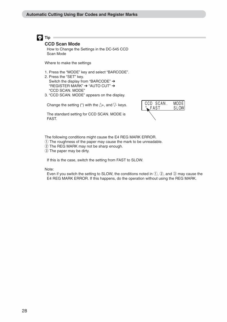
CCD Scan ModeHow to Change the Settings in the DC-545 CCDScan Mode
Where to make the settings
1. Press the “MODE” key and select “BARCODE”.2. Press the “SET” key.
Switch the display from “BARCODE” ➔“REGISTER MARK” ➔ “AUTO CUT” ➔“CCD SCAN. MODE”
3. “CCD SCAN. MODE” appears on the display.
Change the setting (*) with the +, and - keys.
The standard setting for CCD SCAN. MODE isFAST.
The following conditions might cause the E4 REG MARK ERROR.q The roughness of the paper may cause the mark to be unreadable.w The REG MARK may not be sharp enough.e The paper may be dirty.
If this is the case, switch the setting from FAST to SLOW.
Note:Even if you switch the setting to SLOW, the conditions noted in q, w, and e may cause theE4 REG MARK ERROR. If this happens, do the operation without using the REG MARK.
Automatic Cutting Using Bar Codes and Register Marks
CCD SCAN. MODE * FAST SLOW
Docu Cutter(HCEX) 3_26-29 03.12.8, 3:09 PM28
29
2
1
3
Operating Instructions - D
C545 H
CE
X
About the Waste Tray
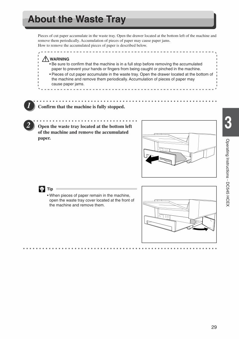
Pieces of cut paper accumulate in the waste tray. Open the drawer located at the bottom left of the machine andremove them periodically. Accumulation of pieces of paper may cause paper jams.How to remove the accumulated pieces of paper is described below.
WARNING• Be sure to confirm that the machine is in a full stop before removing the accumulated
paper to prevent your hands or fingers from being caught or pinched in the machine.• Pieces of cut paper accumulate in the waste tray. Open the drawer located at the bottom of
the machine and remove them periodically. Accumulation of pieces of paper maycause paper jams.
○ ○ ○ ○ ○ ○ ○ ○ ○ ○ ○ ○ ○ ○ ○ ○ ○ ○ ○ ○ ○ ○ ○ ○ ○ ○ ○ ○ ○ ○ ○ ○ ○ ○ ○ ○ ○ ○ ○ ○ ○ ○ ○ ○ ○ ○ ○ ○ ○ ○ ○ ○ ○ ○ ○ ○ ○ ○
Confirm that the machine is fully stopped.
○ ○ ○ ○ ○ ○ ○ ○ ○ ○ ○ ○ ○ ○ ○ ○ ○ ○ ○ ○ ○ ○ ○ ○ ○ ○ ○ ○ ○ ○ ○ ○ ○
Open the waste tray located at the bottom leftof the machine and remove the accumulatedpaper.
Tip
• When pieces of paper remain in the machine,open the waste tray cover located at the front ofthe machine and remove them.
○ ○ ○ ○ ○ ○ ○ ○ ○ ○ ○ ○ ○ ○ ○ ○ ○ ○ ○ ○ ○ ○ ○ ○ ○ ○ ○ ○ ○ ○ ○ ○ ○ ○ ○ ○ ○ ○ ○ ○ ○ ○ ○ ○ ○ ○ ○ ○ ○ ○ ○ ○ ○ ○ ○ ○ ○ ○ ○ ○ ○
Docu Cutter(HCEX) 3_26-29 03.12.8, 3:09 PM29
30
Troubleshooting - DC545 HCEXThis chapter describes what to do when an error has occurred and how to deal with paper jams and error
messages.
Chapter 4
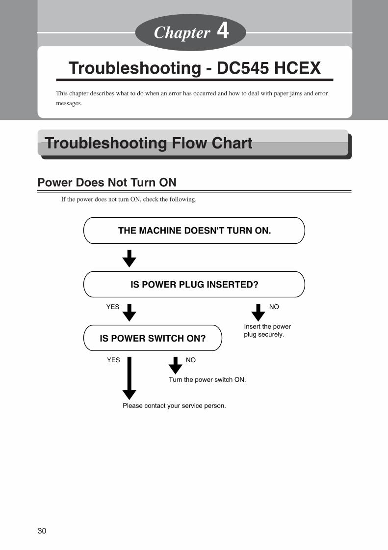
Power Does Not Turn ONIf the power does not turn ON, check the following.
IS POWER PLUG INSERTED?
THE MACHINE DOESN'T TURN ON.
IS POWER SWITCH ON?Insert the power plug securely.
Turn the power switch ON.
Please contact your service person.
NOYES
NOYES
Troubleshooting Flow Chart
Docu Cutter(HCEX) 4_30-52 03.12.8, 3:09 PM30
31
6
2
1
4
Troubleshooting - DC
545 HC
EX
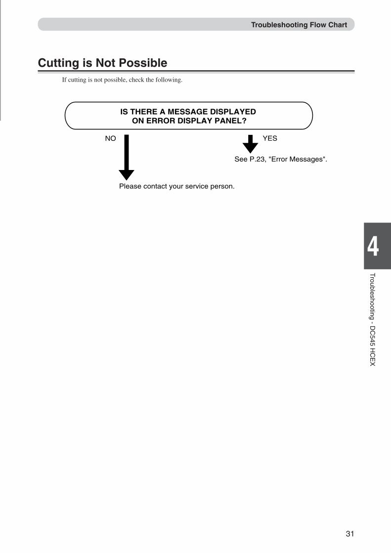
Cutting is Not PossibleIf cutting is not possible, check the following.
IS THERE A MESSAGE DISPLAYED ON ERROR DISPLAY PANEL?
See P.23, "Error Messages".
Please contact your service person.
YESNO
Troubleshooting Flow Chart
Docu Cutter(HCEX) 4_30-52 03.12.8, 3:09 PM31
32
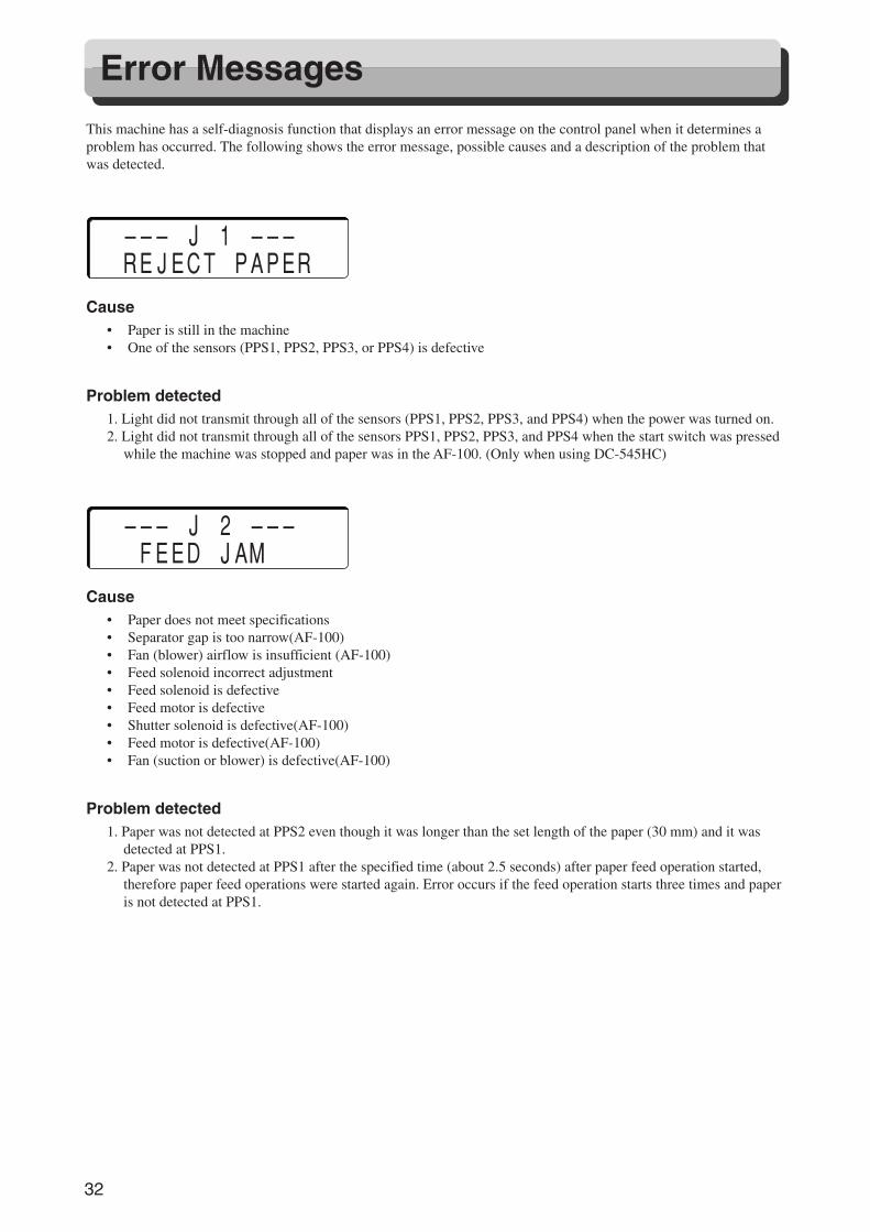
This machine has a self-diagnosis function that displays an error message on the control panel when it determines aproblem has occurred. The following shows the error message, possible causes and a description of the problem thatwas detected.
––– J 1 ––– REJECT PAPERCause
• Paper is still in the machine• One of the sensors (PPS1, PPS2, PPS3, or PPS4) is defective
Problem detected1. Light did not transmit through all of the sensors (PPS1, PPS2, PPS3, and PPS4) when the power was turned on.2. Light did not transmit through all of the sensors PPS1, PPS2, PPS3, and PPS4 when the start switch was pressed
while the machine was stopped and paper was in the AF-100. (Only when using DC-545HC)
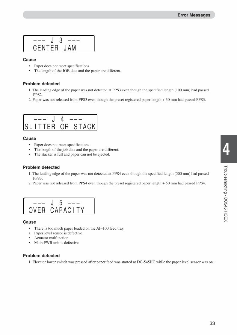
––– J 2 ––– FEED JAMCause
• Paper does not meet specifications• Separator gap is too narrow(AF-100)• Fan (blower) airflow is insufficient (AF-100)• Feed solenoid incorrect adjustment• Feed solenoid is defective• Feed motor is defective• Shutter solenoid is defective(AF-100)• Feed motor is defective(AF-100)• Fan (suction or blower) is defective(AF-100)
Problem detected1. Paper was not detected at PPS2 even though it was longer than the set length of the paper (30 mm) and it was
detected at PPS1.2. Paper was not detected at PPS1 after the specified time (about 2.5 seconds) after paper feed operation started,
therefore paper feed operations were started again. Error occurs if the feed operation starts three times and paperis not detected at PPS1.
Error Messages
Docu Cutter(HCEX) 4_30-52 03.12.8, 3:09 PM32
33
6
2
1
4
Troubleshooting - DC
545 HC
EX
––– J 3 ––– CENTER JAMCause
• Paper does not meet specifications• The length of the JOB data and the paper are different.
Problem detected1. The leading edge of the paper was not detected at PPS3 even though the specified length (100 mm) had passed
PPS2.2. Paper was not released from PPS3 even though the preset registered paper length + 30 mm had passed PPS3.
––– J 4 –––SLITTER OR STACKCause
• Paper does not meet specifications• The length of the job data and the paper are different.• The stacker is full and paper can not be ejected.
Problem detected1. The leading edge of the paper was not detected at PPS4 even though the specified length (500 mm) had passed
PPS3.2. Paper was not released from PPS4 even though the preset registered paper length + 50 mm had passed PPS4.
––– J 5 ––– OVER CAPACITYCause
• There is too much paper loaded on the AF-100 feed tray.• Paper level sensor is defective• Actuator malfunction• Main PWB unit is defective
Problem detected1. Elevator lower switch was pressed after paper feed was started at DC-545HC while the paper level sensor was on.
Error Messages
Docu Cutter(HCEX) 4_30-52 03.12.8, 3:10 PM33
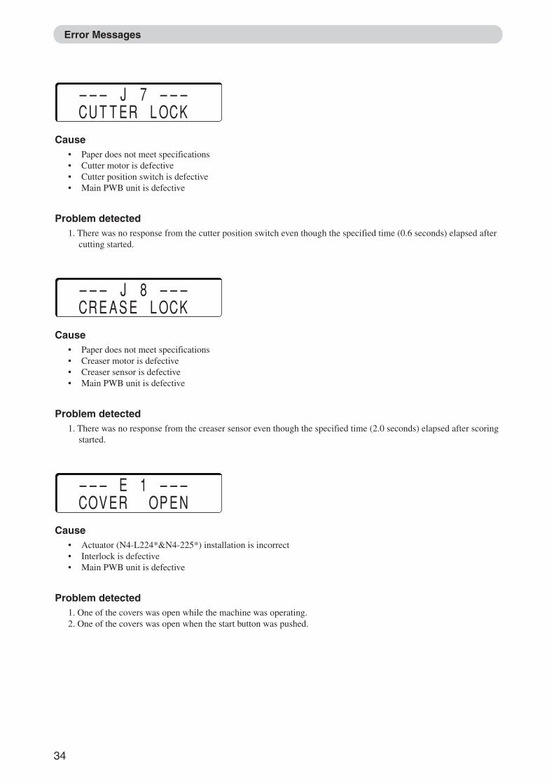
34
––– J 7 ––– CUTTER LOCKCause
• Paper does not meet specifications• Cutter motor is defective• Cutter position switch is defective• Main PWB unit is defective
Problem detected1. There was no response from the cutter position switch even though the specified time (0.6 seconds) elapsed after
cutting started.
––– J 8 ––– CREASE LOCKCause
• Paper does not meet specifications• Creaser motor is defective• Creaser sensor is defective• Main PWB unit is defective
Problem detected1. There was no response from the creaser sensor even though the specified time (2.0 seconds) elapsed after scoring
started.
––– E 1 ––– COVER OPENCause
• Actuator (N4-L224*&N4-225*) installation is incorrect• Interlock is defective• Main PWB unit is defective
Problem detected1. One of the covers was open while the machine was operating.2. One of the covers was open when the start button was pushed.
Error Messages
Docu Cutter(HCEX) 4_30-52 03.12.8, 3:10 PM34
35
6
2
1
4
Troubleshooting - DC
545 HC
EX
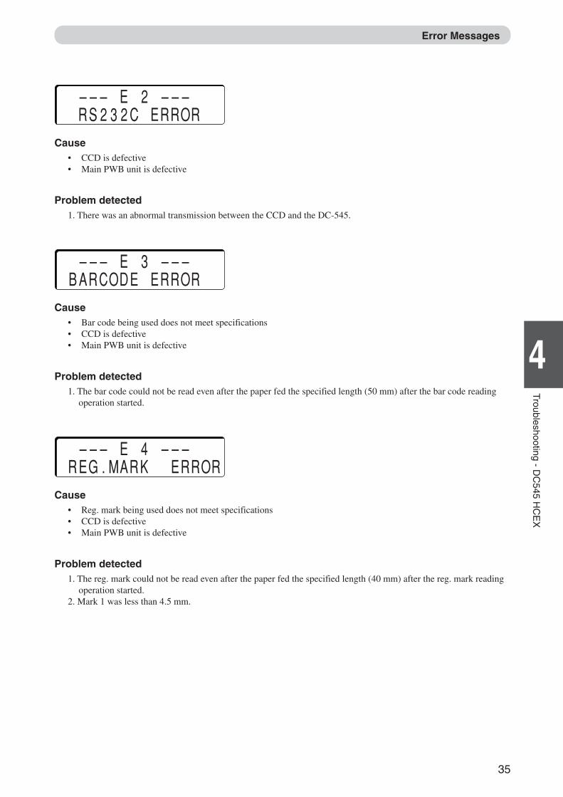
––– E 2 ––– RS232C ERRORCause
• CCD is defective• Main PWB unit is defective
Problem detected1. There was an abnormal transmission between the CCD and the DC-545.
––– E 3 ––– BARCODE ERRORCause
• Bar code being used does not meet specifications• CCD is defective• Main PWB unit is defective
Problem detected1. The bar code could not be read even after the paper fed the specified length (50 mm) after the bar code reading
operation started.
––– E 4 ––– REG.MARK ERRORCause
• Reg. mark being used does not meet specifications• CCD is defective• Main PWB unit is defective
Problem detected1. The reg. mark could not be read even after the paper fed the specified length (40 mm) after the reg. mark reading
operation started.2. Mark 1 was less than 4.5 mm.
Error Messages
Docu Cutter(HCEX) 4_30-52 03.12.8, 3:10 PM35
36
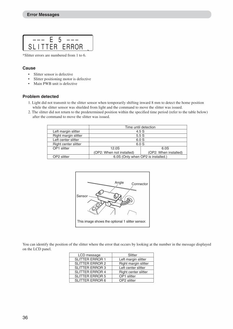
––– E 5 ––– SLITTER ERROR * *Slitter errors are numbered from 1 to 6.
Cause• Slitter sensor is defective• Slitter positioning motor is defective• Main PWB unit is defective
Problem detected1. Light did not transmit to the slitter sensor when temporarily shifting inward 8 mm to detect the home position
while the slitter sensor was shielded from light and the command to move the slitter was issued.2. The slitter did not return to the predetermined position within the specified time period (refer to the table below)
after the command to move the slitter was issued.
Left margin slitterRight margin slitterLeft center slitterRight center slitterOP1 slitter
OP2 slitter
Time until detection4.5 S5.5 S6.0 S6.0 S
12.0S 6.0S(OP2: When not installed) (OP2: When installed)
6.0S (Only when OP2 is installed.)
This image shows the optional 1 slitter sensor.
Angle
Sensor
Connector
LCD message SlitterSLITTER ERROR 1 Left margin slitterSLITTER ERROR 2 Right margin slitterSLITTER ERROR 3 Left center slitterSLITTER ERROR 4 Right center slitterSLITTER ERROR 5 OP1 slitterSLITTER ERROR 6 OP2 slitter
You can identify the position of the slitter where the error that occurs by looking at the number in the message displayedon the LCD panel.
Error Messages
Docu Cutter(HCEX) 4_30-52 03.12.8, 3:10 PM36
37
6
2
1
4
Troubleshooting - DC
545 HC
EX
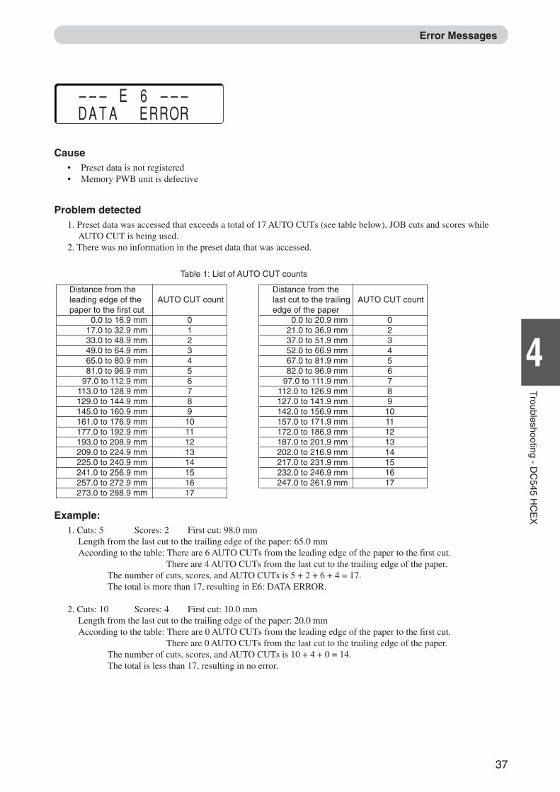
––– E 6 ––– DATA ERROR
Cause• Preset data is not registered• Memory PWB unit is defective
Problem detected1. Preset data was accessed that exceeds a total of 17 AUTO CUTs (see table below), JOB cuts and scores while
AUTO CUT is being used.2. There was no information in the preset data that was accessed.
Example:1. Cuts: 5 Scores: 2 First cut: 98.0 mm
Length from the last cut to the trailing edge of the paper: 65.0 mmAccording to the table: There are 6 AUTO CUTs from the leading edge of the paper to the first cut.
There are 4 AUTO CUTs from the last cut to the trailing edge of the paper.The number of cuts, scores, and AUTO CUTs is 5 + 2 + 6 + 4 = 17.The total is more than 17, resulting in E6: DATA ERROR.
2. Cuts: 10 Scores: 4 First cut: 10.0 mmLength from the last cut to the trailing edge of the paper: 20.0 mmAccording to the table: There are 0 AUTO CUTs from the leading edge of the paper to the first cut.
There are 0 AUTO CUTs from the last cut to the trailing edge of the paper.The number of cuts, scores, and AUTO CUTs is 10 + 4 + 0 = 14.The total is less than 17, resulting in no error.
Table 1: List of AUTO CUT counts
Distance from theleading edge of thepaper to the first cut
0.0 to 16.9 mm17.0 to 32.9 mm33.0 to 48.9 mm49.0 to 64.9 mm65.0 to 80.9 mm81.0 to 96.9 mm
97.0 to 112.9 mm113.0 to 128.9 mm129.0 to 144.9 mm145.0 to 160.9 mm161.0 to 176.9 mm177.0 to 192.9 mm193.0 to 208.9 mm209.0 to 224.9 mm225.0 to 240.9 mm241.0 to 256.9 mm257.0 to 272.9 mm273.0 to 288.9 mm
AUTO CUT count
0123456789
1011121314151617
Distance from thelast cut to the trailingedge of the paper
0.0 to 20.9 mm21.0 to 36.9 mm37.0 to 51.9 mm52.0 to 66.9 mm67.0 to 81.9 mm82.0 to 96.9 mm
97.0 to 111.9 mm112.0 to 126.9 mm127.0 to 141.9 mm142.0 to 156.9 mm157.0 to 171.9 mm172.0 to 186.9 mm187.0 to 201.9 mm202.0 to 216.9 mm217.0 to 231.9 mm232.0 to 246.9 mm247.0 to 261.9 mm
AUTO CUT count
023456789
1011121314151617
Error Messages
Docu Cutter(HCEX) 4_30-52 03.12.8, 3:10 PM37
38
––– E 7 –––CONNECTION ERRORCause
• Bad connection between AF-100 and DC-545• Feed PCB unit is defective• Main PWB unit is defective
Problem detected1. Can not confirm connection between AF-100 and DC-545 while machine is operating.
––– E 8 ––– ELEVATOR ERRORCause
• Elevator upper switch is defective• Elevator lower switch is defective• Elevator motor is defective• Paper level sensor is defective• Feed PCB unit is defective• Main PWB unit is defective
Problem detected1. Elevator was not detected at elevator upper switch, elevator lower switch, or paper level sensor after the specified
time (* seconds) after the command to operator the elevator was issued.* 10 seconds when rising at start-up, 3.5 seconds when paper is being fed, 9 seconds when going down at shut-down
NOTE :• When this error occurs there is a possibility that the screws pressing on the spring, or the elevator
up and down switch are damaged.
Error Messages
Docu Cutter(HCEX) 4_30-52 03.12.8, 3:10 PM38
39
6
2
1
4
Troubleshooting - DC
545 HC
EX
When a Paper Jam Has Occurred
When a paper jam has occurred, the JAM lamp blinks and a message is displayed on the LCD panel.
WARNING• Do not touch the blade (with the WARNING sticker attached). Doing so may cause injury.
(aP.6, “Warning Sticker”)• Before removing paper from under the front and rear covers, make sure the machine is fullystopped. Use the tweezers that come with the machine to prevent your hands or fingers frombeing caught or pinched. (aP.6, “Warning Sticker”)
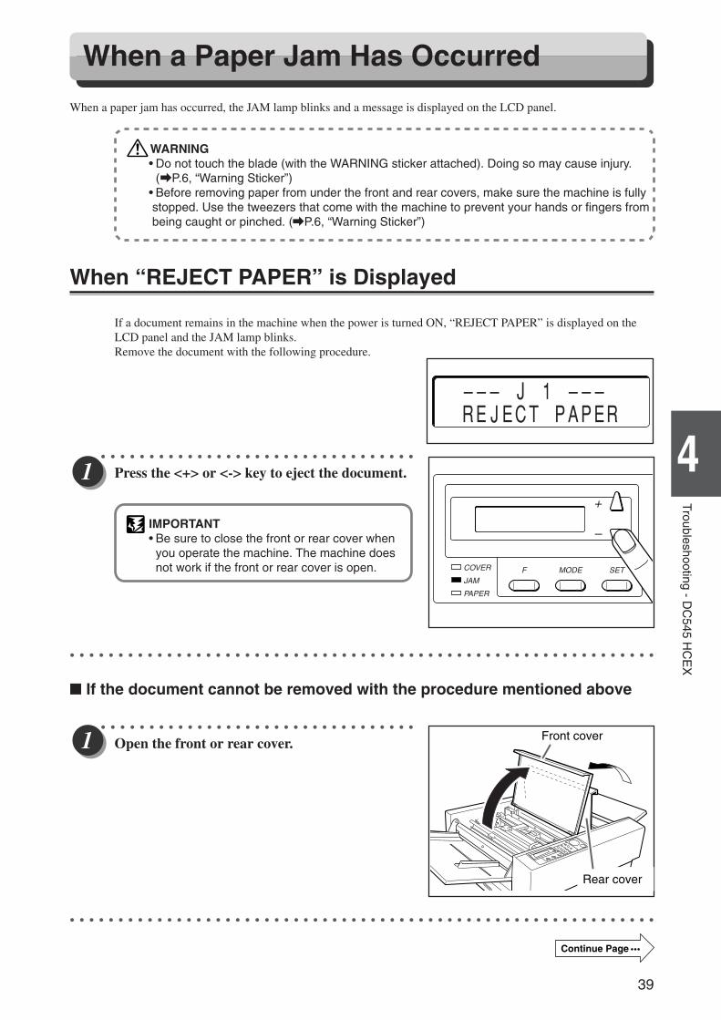
When “REJECT PAPER” is Displayed
If a document remains in the machine when the power is turned ON, “REJECT PAPER” is displayed on theLCD panel and the JAM lamp blinks.Remove the document with the following procedure.
○ ○ ○ ○ ○ ○ ○ ○ ○ ○ ○ ○ ○ ○ ○ ○ ○ ○ ○ ○ ○ ○ ○ ○ ○ ○ ○ ○ ○ ○ ○ ○ ○
Press the <+> or <-> key to eject the document.
IMPORTANT• Be sure to close the front or rear cover when
you operate the machine. The machine doesnot work if the front or rear cover is open.
○ ○ ○ ○ ○ ○ ○ ○ ○ ○ ○ ○ ○ ○ ○ ○ ○ ○ ○ ○ ○ ○ ○ ○ ○ ○ ○ ○ ○ ○ ○ ○ ○ ○ ○ ○ ○ ○ ○ ○ ○ ○ ○ ○ ○ ○ ○ ○ ○ ○ ○ ○ ○ ○ ○ ○ ○ ○ ○ ○ ○
� If the document cannot be removed with the procedure mentioned above
○ ○ ○ ○ ○ ○ ○ ○ ○ ○ ○ ○ ○ ○ ○ ○ ○ ○ ○ ○ ○ ○ ○ ○ ○ ○ ○ ○ ○ ○ ○ ○ ○
Open the front or rear cover.
○ ○ ○ ○ ○ ○ ○ ○ ○ ○ ○ ○ ○ ○ ○ ○ ○ ○ ○ ○ ○ ○ ○ ○ ○ ○ ○ ○ ○ ○ ○ ○ ○ ○ ○ ○ ○ ○ ○ ○ ○ ○ ○ ○ ○ ○ ○ ○ ○ ○ ○ ○ ○ ○ ○ ○ ○ ○ ○ ○ ○
––– J 1 ––– REJECT PAPER
COVER
JAMF
PAPER
MODE SET
+
–
Front cover
Rear cover
Continue Page •••
Docu Cutter(HCEX) 4_30-52 03.12.8, 3:10 PM39
40
Front cover
Rear cover
○ ○ ○ ○ ○ ○ ○ ○ ○ ○ ○ ○ ○ ○ ○ ○ ○ ○ ○ ○ ○ ○ ○ ○ ○ ○ ○ ○ ○ ○ ○ ○ ○
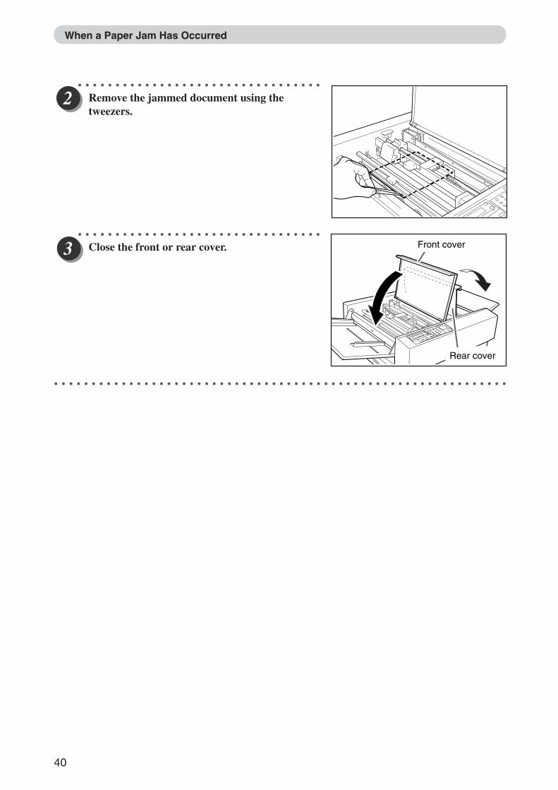
Remove the jammed document using thetweezers.
○ ○ ○ ○ ○ ○ ○ ○ ○ ○ ○ ○ ○ ○ ○ ○ ○ ○ ○ ○ ○ ○ ○ ○ ○ ○ ○ ○ ○ ○ ○ ○ ○
Close the front or rear cover.
○ ○ ○ ○ ○ ○ ○ ○ ○ ○ ○ ○ ○ ○ ○ ○ ○ ○ ○ ○ ○ ○ ○ ○ ○ ○ ○ ○ ○ ○ ○ ○ ○ ○ ○ ○ ○ ○ ○ ○ ○ ○ ○ ○ ○ ○ ○ ○ ○ ○ ○ ○ ○ ○ ○ ○ ○ ○ ○ ○ ○
When a Paper Jam Has Occurred
Docu Cutter(HCEX) 4_30-52 03.12.8, 3:10 PM40
41
6
2
1
4
Troubleshooting - DC
545 HC
EX
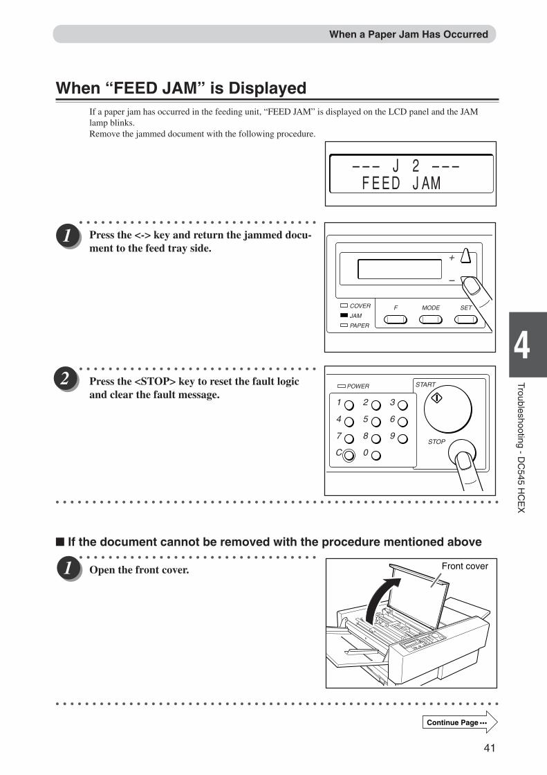
When “FEED JAM” is DisplayedIf a paper jam has occurred in the feeding unit, “FEED JAM” is displayed on the LCD panel and the JAMlamp blinks.Remove the jammed document with the following procedure.
○ ○ ○ ○ ○ ○ ○ ○ ○ ○ ○ ○ ○ ○ ○ ○ ○ ○ ○ ○ ○ ○ ○ ○ ○ ○ ○ ○ ○ ○ ○ ○ ○
Press the <-> key and return the jammed docu-ment to the feed tray side.
○ ○ ○ ○ ○ ○ ○ ○ ○ ○ ○ ○ ○ ○ ○ ○ ○ ○ ○ ○ ○ ○ ○ ○ ○ ○ ○ ○ ○ ○ ○ ○ ○
Press the <STOP> key to reset the fault logicand clear the fault message.
○ ○ ○ ○ ○ ○ ○ ○ ○ ○ ○ ○ ○ ○ ○ ○ ○ ○ ○ ○ ○ ○ ○ ○ ○ ○ ○ ○ ○ ○ ○ ○ ○ ○ ○ ○ ○ ○ ○ ○ ○ ○ ○ ○ ○ ○ ○ ○ ○ ○ ○ ○ ○ ○ ○ ○ ○ ○ ○ ○ ○
� If the document cannot be removed with the procedure mentioned above○ ○ ○ ○ ○ ○ ○ ○ ○ ○ ○ ○ ○ ○ ○ ○ ○ ○ ○ ○ ○ ○ ○ ○ ○ ○ ○ ○ ○ ○ ○ ○ ○
Open the front cover.
○ ○ ○ ○ ○ ○ ○ ○ ○ ○ ○ ○ ○ ○ ○ ○ ○ ○ ○ ○ ○ ○ ○ ○ ○ ○ ○ ○ ○ ○ ○ ○ ○ ○ ○ ○ ○ ○ ○ ○ ○ ○ ○ ○ ○ ○ ○ ○ ○ ○ ○ ○ ○ ○ ○ ○ ○ ○ ○ ○ ○
When a Paper Jam Has Occurred
––– J 2 ––– FEED JAM
COVER
JAMF
PAPER
MODE SET
+
–
Front cover
1
4
7
C
2
5
8
0
3
6
9
POWER START
STOP
Continue Page •••
Docu Cutter(HCEX) 4_30-52 03.12.8, 3:10 PM41
42
○ ○ ○ ○ ○ ○ ○ ○ ○ ○ ○ ○ ○ ○ ○ ○ ○ ○ ○ ○ ○ ○ ○ ○ ○ ○ ○ ○ ○ ○ ○ ○ ○
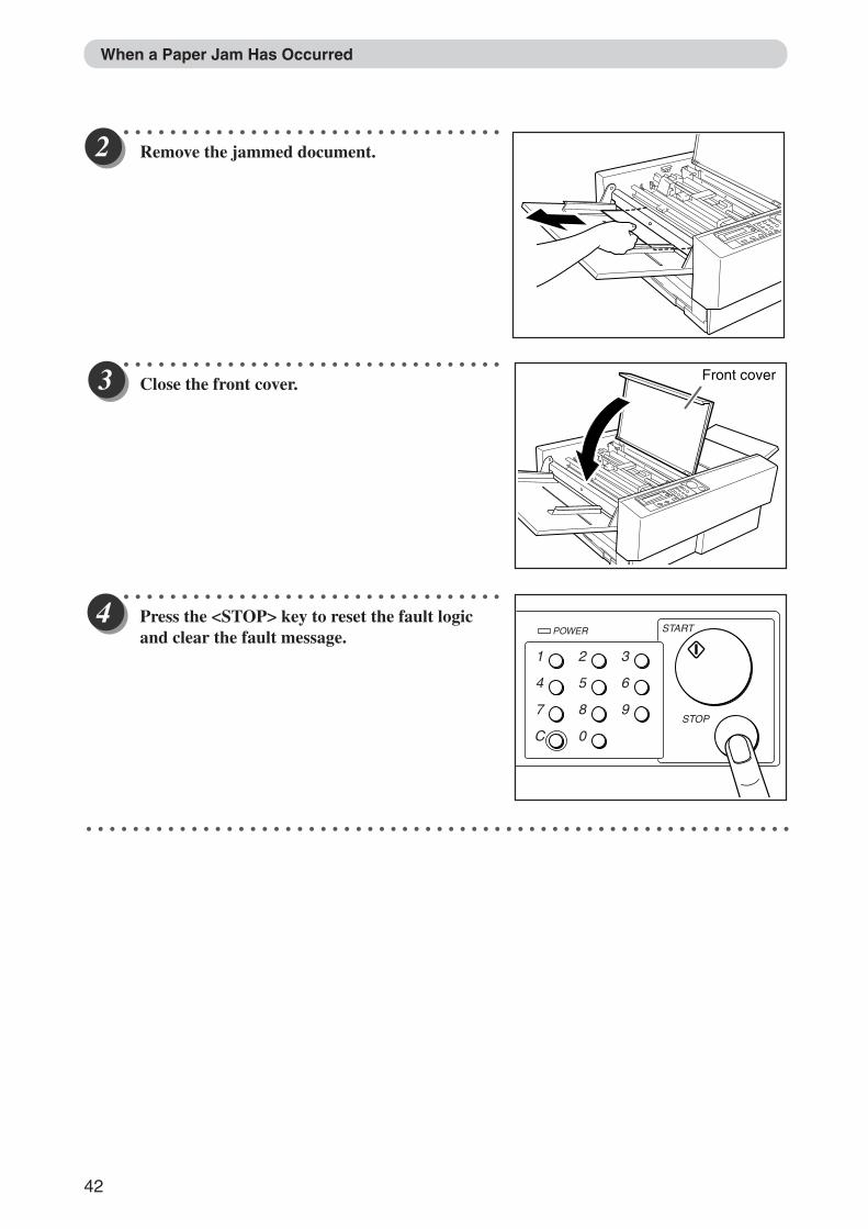
Remove the jammed document.
○ ○ ○ ○ ○ ○ ○ ○ ○ ○ ○ ○ ○ ○ ○ ○ ○ ○ ○ ○ ○ ○ ○ ○ ○ ○ ○ ○ ○ ○ ○ ○ ○
Close the front cover.
○ ○ ○ ○ ○ ○ ○ ○ ○ ○ ○ ○ ○ ○ ○ ○ ○ ○ ○ ○ ○ ○ ○ ○ ○ ○ ○ ○ ○ ○ ○ ○ ○
Press the <STOP> key to reset the fault logicand clear the fault message.
○ ○ ○ ○ ○ ○ ○ ○ ○ ○ ○ ○ ○ ○ ○ ○ ○ ○ ○ ○ ○ ○ ○ ○ ○ ○ ○ ○ ○ ○ ○ ○ ○ ○ ○ ○ ○ ○ ○ ○ ○ ○ ○ ○ ○ ○ ○ ○ ○ ○ ○ ○ ○ ○ ○ ○ ○ ○ ○ ○ ○
When a Paper Jam Has Occurred
Front cover
1
4
7
C
2
5
8
0
3
6
9
POWER START
STOP
Docu Cutter(HCEX) 4_30-52 03.12.8, 3:10 PM42

43
6
2
1
4
Troubleshooting - DC
545 HC
EX
When “CENTER JAM” is DisplayedIf a paper jam has occurred in the machine (front), “CENTER JAM” is displayed on the LCD panel and theJAM lamp blinks.Remove the jammed document with the following procedure.
○ ○ ○ ○ ○ ○ ○ ○ ○ ○ ○ ○ ○ ○ ○ ○ ○ ○ ○ ○ ○ ○ ○ ○ ○ ○ ○ ○ ○ ○ ○ ○ ○
Press the <-> key and return the jammeddocument to the feed tray side.
○ ○ ○ ○ ○ ○ ○ ○ ○ ○ ○ ○ ○ ○ ○ ○ ○ ○ ○ ○ ○ ○ ○ ○ ○ ○ ○ ○ ○ ○ ○ ○ ○
Press the <STOP> key to reset the fault logicand clear the fault message.
○ ○ ○ ○ ○ ○ ○ ○ ○ ○ ○ ○ ○ ○ ○ ○ ○ ○ ○ ○ ○ ○ ○ ○ ○ ○ ○ ○ ○ ○ ○ ○ ○ ○ ○ ○ ○ ○ ○ ○ ○ ○ ○ ○ ○ ○ ○ ○ ○ ○ ○ ○ ○ ○ ○ ○ ○ ○ ○ ○ ○
� If the document cannot be removed with the procedure mentioned above○ ○ ○ ○ ○ ○ ○ ○ ○ ○ ○ ○ ○ ○ ○ ○ ○ ○ ○ ○ ○ ○ ○ ○ ○ ○ ○ ○ ○ ○ ○ ○ ○
Open the front cover.
○ ○ ○ ○ ○ ○ ○ ○ ○ ○ ○ ○ ○ ○ ○ ○ ○ ○ ○ ○ ○ ○ ○ ○ ○ ○ ○ ○ ○ ○ ○ ○ ○ ○ ○ ○ ○ ○ ○ ○ ○ ○ ○ ○ ○ ○ ○ ○ ○ ○ ○ ○ ○ ○ ○ ○ ○ ○ ○ ○ ○
––– J 3 ––– CENTER JAM
COVER
JAMF
PAPER
MODE SET
+
–
Front cover
When a Paper Jam Has Occurred
1
4
7
C
2
5
8
0
3
6
9
POWER START
STOP
Continue Page •••
Docu Cutter(HCEX) 4_30-52 03.12.8, 3:10 PM43
44
○ ○ ○ ○ ○ ○ ○ ○ ○ ○ ○ ○ ○ ○ ○ ○ ○ ○ ○ ○ ○ ○ ○ ○ ○ ○ ○ ○ ○ ○ ○ ○ ○
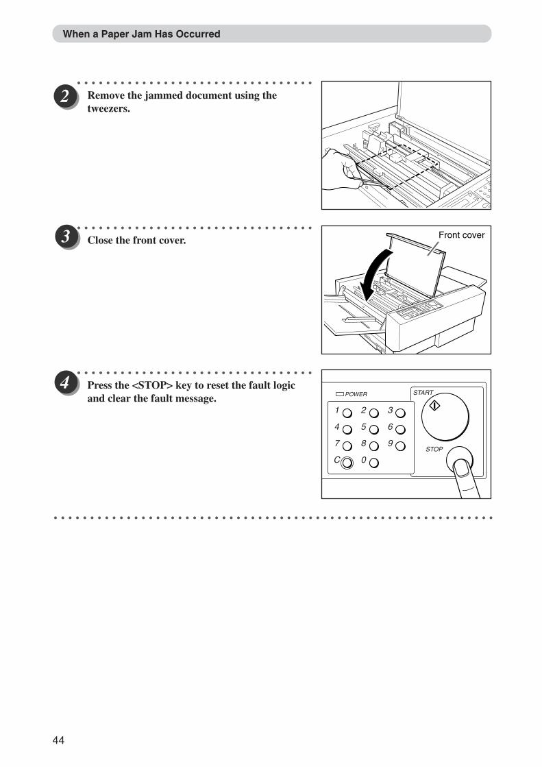
Remove the jammed document using thetweezers.
○ ○ ○ ○ ○ ○ ○ ○ ○ ○ ○ ○ ○ ○ ○ ○ ○ ○ ○ ○ ○ ○ ○ ○ ○ ○ ○ ○ ○ ○ ○ ○ ○
Close the front cover.
○ ○ ○ ○ ○ ○ ○ ○ ○ ○ ○ ○ ○ ○ ○ ○ ○ ○ ○ ○ ○ ○ ○ ○ ○ ○ ○ ○ ○ ○ ○ ○ ○
Press the <STOP> key to reset the fault logicand clear the fault message.
○ ○ ○ ○ ○ ○ ○ ○ ○ ○ ○ ○ ○ ○ ○ ○ ○ ○ ○ ○ ○ ○ ○ ○ ○ ○ ○ ○ ○ ○ ○ ○ ○ ○ ○ ○ ○ ○ ○ ○ ○ ○ ○ ○ ○ ○ ○ ○ ○ ○ ○ ○ ○ ○ ○ ○ ○ ○ ○ ○ ○
When a Paper Jam Has Occurred
Front cover
1
4
7
C
2
5
8
0
3
6
9
POWER START
STOP
Docu Cutter(HCEX) 4_30-52 03.12.8, 3:10 PM44
45
6
2
1
4
Troubleshooting - DC
545 HC
EX
When a Paper Jam Has Occurred
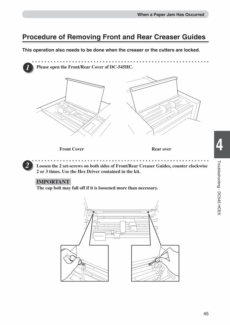
Procedure of Removing Front and Rear Creaser Guides
This operation also needs to be done when the creaser or the cutters are locked.
○ ○ ○ ○ ○ ○ ○ ○ ○ ○ ○ ○ ○ ○ ○ ○ ○ ○ ○ ○ ○ ○ ○ ○ ○ ○ ○ ○ ○ ○ ○ ○ ○ ○ ○ ○ ○ ○ ○ ○ ○ ○ ○ ○ ○ ○ ○ ○ ○ ○ ○ ○ ○ ○ ○ ○ ○ ○
Please open the Front/Rear Cover of DC-545HC.
Front Cover Rear over
○ ○ ○ ○ ○ ○ ○ ○ ○ ○ ○ ○ ○ ○ ○ ○ ○ ○ ○ ○ ○ ○ ○ ○ ○ ○ ○ ○ ○ ○ ○ ○ ○ ○ ○ ○ ○ ○ ○ ○ ○ ○ ○ ○ ○ ○ ○ ○ ○ ○ ○ ○ ○ ○ ○ ○ ○ ○
Loosen the 2 set-screws on both sides of Front/Rear Creaser Guides, counter clockwise2 or 3 times. Use the Hex Driver contained in the kit.
IMPORTANTThe cap bolt may fall off if it is loosened more than necessary.
Docu Cutter(HCEX) 4_30-52 03.12.8, 3:10 PM45
46
When a Paper Jam Has Occurred
○ ○ ○ ○ ○ ○ ○ ○ ○ ○ ○ ○ ○ ○ ○ ○ ○ ○ ○ ○ ○ ○ ○ ○ ○ ○ ○ ○ ○ ○ ○ ○ ○ ○ ○ ○ ○ ○ ○ ○ ○ ○ ○ ○ ○ ○ ○ ○ ○ ○ ○ ○ ○ ○ ○ ○ ○ ○
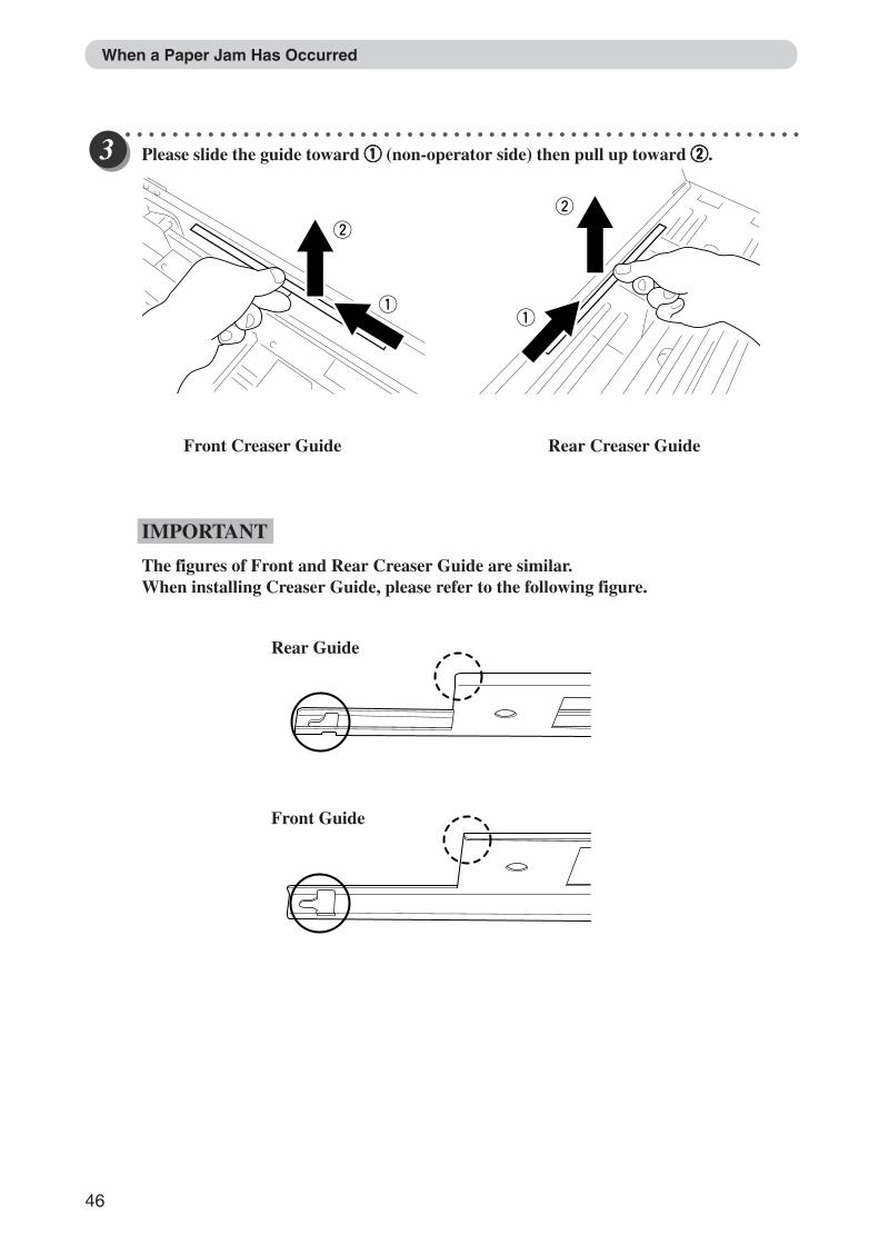
Please slide the guide toward qqqqq (non-operator side) then pull up toward wwwww.
Front Creaser Guide Rear Creaser Guide
IMPORTANT
The figures of Front and Rear Creaser Guide are similar.When installing Creaser Guide, please refer to the following figure.
Rear Guide
Front Guide
Docu Cutter(HCEX) 4_30-52 03.12.8, 3:10 PM46
47
6
2
1
4
Troubleshooting - DC
545 HC
EX
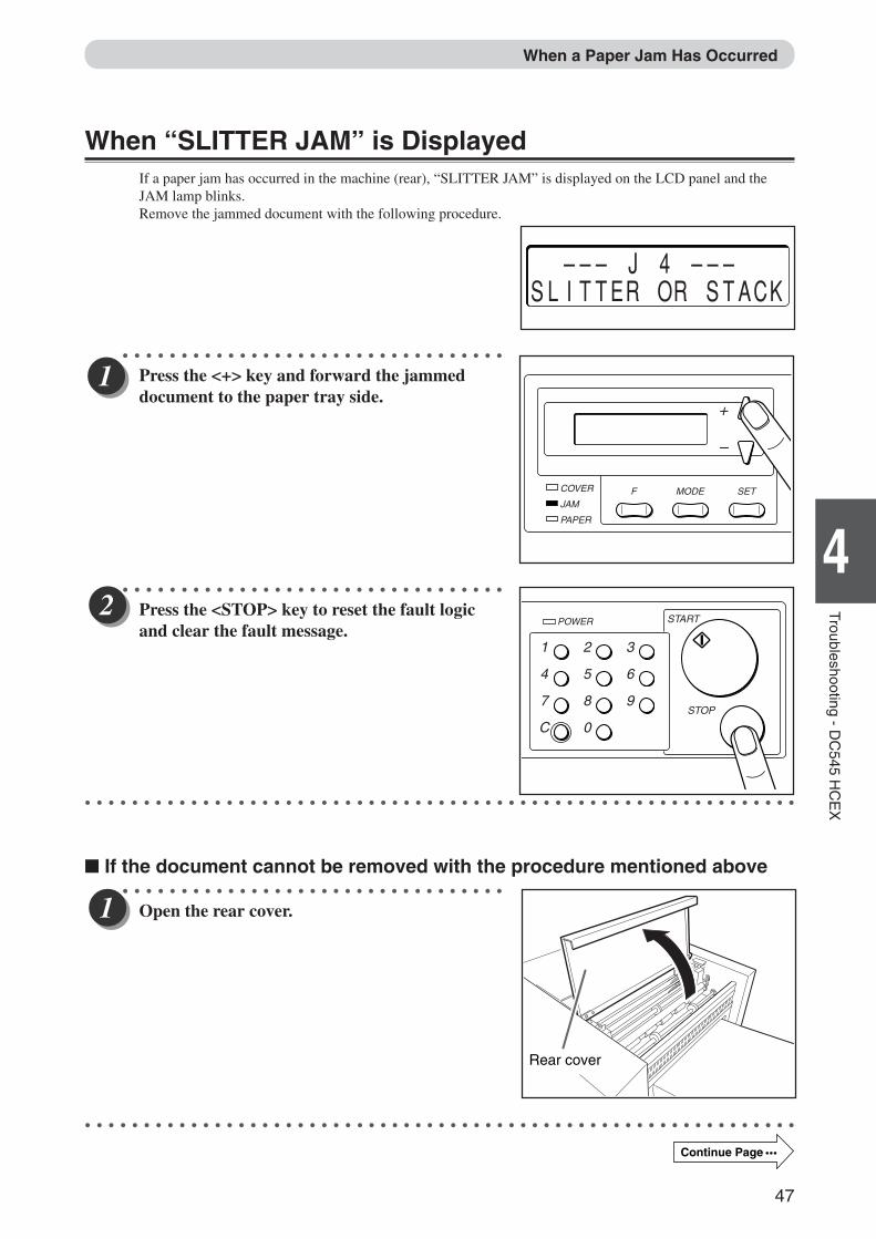
When “SLITTER JAM” is DisplayedIf a paper jam has occurred in the machine (rear), “SLITTER JAM” is displayed on the LCD panel and theJAM lamp blinks.Remove the jammed document with the following procedure.
○ ○ ○ ○ ○ ○ ○ ○ ○ ○ ○ ○ ○ ○ ○ ○ ○ ○ ○ ○ ○ ○ ○ ○ ○ ○ ○ ○ ○ ○ ○ ○ ○
Press the <+> key and forward the jammeddocument to the paper tray side.
○ ○ ○ ○ ○ ○ ○ ○ ○ ○ ○ ○ ○ ○ ○ ○ ○ ○ ○ ○ ○ ○ ○ ○ ○ ○ ○ ○ ○ ○ ○ ○ ○
Press the <STOP> key to reset the fault logicand clear the fault message.
○ ○ ○ ○ ○ ○ ○ ○ ○ ○ ○ ○ ○ ○ ○ ○ ○ ○ ○ ○ ○ ○ ○ ○ ○ ○ ○ ○ ○ ○ ○ ○ ○ ○ ○ ○ ○ ○ ○ ○ ○ ○ ○ ○ ○ ○ ○ ○ ○ ○ ○ ○ ○ ○ ○ ○ ○ ○ ○ ○ ○
� If the document cannot be removed with the procedure mentioned above○ ○ ○ ○ ○ ○ ○ ○ ○ ○ ○ ○ ○ ○ ○ ○ ○ ○ ○ ○ ○ ○ ○ ○ ○ ○ ○ ○ ○ ○ ○ ○ ○
Open the rear cover.
○ ○ ○ ○ ○ ○ ○ ○ ○ ○ ○ ○ ○ ○ ○ ○ ○ ○ ○ ○ ○ ○ ○ ○ ○ ○ ○ ○ ○ ○ ○ ○ ○ ○ ○ ○ ○ ○ ○ ○ ○ ○ ○ ○ ○ ○ ○ ○ ○ ○ ○ ○ ○ ○ ○ ○ ○ ○ ○ ○ ○
––– J 4 –––SLITTER OR STACK
COVER
JAMF
PAPER
MODE SET
+
–
Rear cover
When a Paper Jam Has Occurred
1
4
7
C
2
5
8
0
3
6
9
POWER START
STOP
Continue Page •••
Docu Cutter(HCEX) 4_30-52 03.12.8, 3:10 PM47
48
Rear cover
○ ○ ○ ○ ○ ○ ○ ○ ○ ○ ○ ○ ○ ○ ○ ○ ○ ○ ○ ○ ○ ○ ○ ○ ○ ○ ○ ○ ○ ○ ○ ○ ○
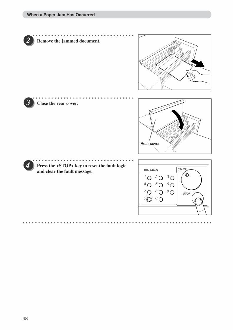
Remove the jammed document.
○ ○ ○ ○ ○ ○ ○ ○ ○ ○ ○ ○ ○ ○ ○ ○ ○ ○ ○ ○ ○ ○ ○ ○ ○ ○ ○ ○ ○ ○ ○ ○ ○
Close the rear cover.
○ ○ ○ ○ ○ ○ ○ ○ ○ ○ ○ ○ ○ ○ ○ ○ ○ ○ ○ ○ ○ ○ ○ ○ ○ ○ ○ ○ ○ ○ ○ ○ ○
Press the <STOP> key to reset the fault logicand clear the fault message.
○ ○ ○ ○ ○ ○ ○ ○ ○ ○ ○ ○ ○ ○ ○ ○ ○ ○ ○ ○ ○ ○ ○ ○ ○ ○ ○ ○ ○ ○ ○ ○ ○ ○ ○ ○ ○ ○ ○ ○ ○ ○ ○ ○ ○ ○ ○ ○ ○ ○ ○ ○ ○ ○ ○ ○ ○ ○ ○ ○ ○
When a Paper Jam Has Occurred
1
4
7
C
2
5
8
0
3
6
9
POWER START
STOP
Docu Cutter(HCEX) 4_30-52 03.12.8, 3:10 PM48
49
6
2
1
4
Troubleshooting - DC
545 HC
EX
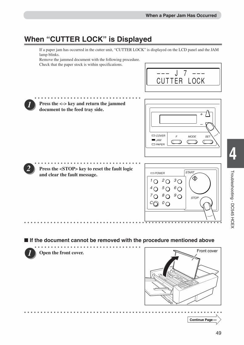
When “CUTTER LOCK” is DisplayedIf a paper jam has occurred in the cutter unit, “CUTTER LOCK” is displayed on the LCD panel and the JAMlamp blinks.Remove the jammed document with the following procedure.Check that the paper stock is within specifications.
○ ○ ○ ○ ○ ○ ○ ○ ○ ○ ○ ○ ○ ○ ○ ○ ○ ○ ○ ○ ○ ○ ○ ○ ○ ○ ○ ○ ○ ○ ○ ○ ○
Press the <-> key and return the jammeddocument to the feed tray side.
○ ○ ○ ○ ○ ○ ○ ○ ○ ○ ○ ○ ○ ○ ○ ○ ○ ○ ○ ○ ○ ○ ○ ○ ○ ○ ○ ○ ○ ○ ○ ○ ○
Press the <STOP> key to reset the fault logicand clear the fault message.
○ ○ ○ ○ ○ ○ ○ ○ ○ ○ ○ ○ ○ ○ ○ ○ ○ ○ ○ ○ ○ ○ ○ ○ ○ ○ ○ ○ ○ ○ ○ ○ ○ ○ ○ ○ ○ ○ ○ ○ ○ ○ ○ ○ ○ ○ ○ ○ ○ ○ ○ ○ ○ ○ ○ ○ ○ ○ ○ ○ ○
� If the document cannot be removed with the procedure mentioned above○ ○ ○ ○ ○ ○ ○ ○ ○ ○ ○ ○ ○ ○ ○ ○ ○ ○ ○ ○ ○ ○ ○ ○ ○ ○ ○ ○ ○ ○ ○ ○ ○
Open the front cover.
○ ○ ○ ○ ○ ○ ○ ○ ○ ○ ○ ○ ○ ○ ○ ○ ○ ○ ○ ○ ○ ○ ○ ○ ○ ○ ○ ○ ○ ○ ○ ○ ○ ○ ○ ○ ○ ○ ○ ○ ○ ○ ○ ○ ○ ○ ○ ○ ○ ○ ○ ○ ○ ○ ○ ○ ○ ○ ○ ○ ○
––– J 7 ––– CUTTER LOCK
COVER
JAMF
PAPER
MODE SET
+
–
Front cover
When a Paper Jam Has Occurred
1
4
7
C
2
5
8
0
3
6
9
POWER START
STOP
Continue Page •••
Docu Cutter(HCEX) 4_30-52 03.12.8, 3:10 PM49
50
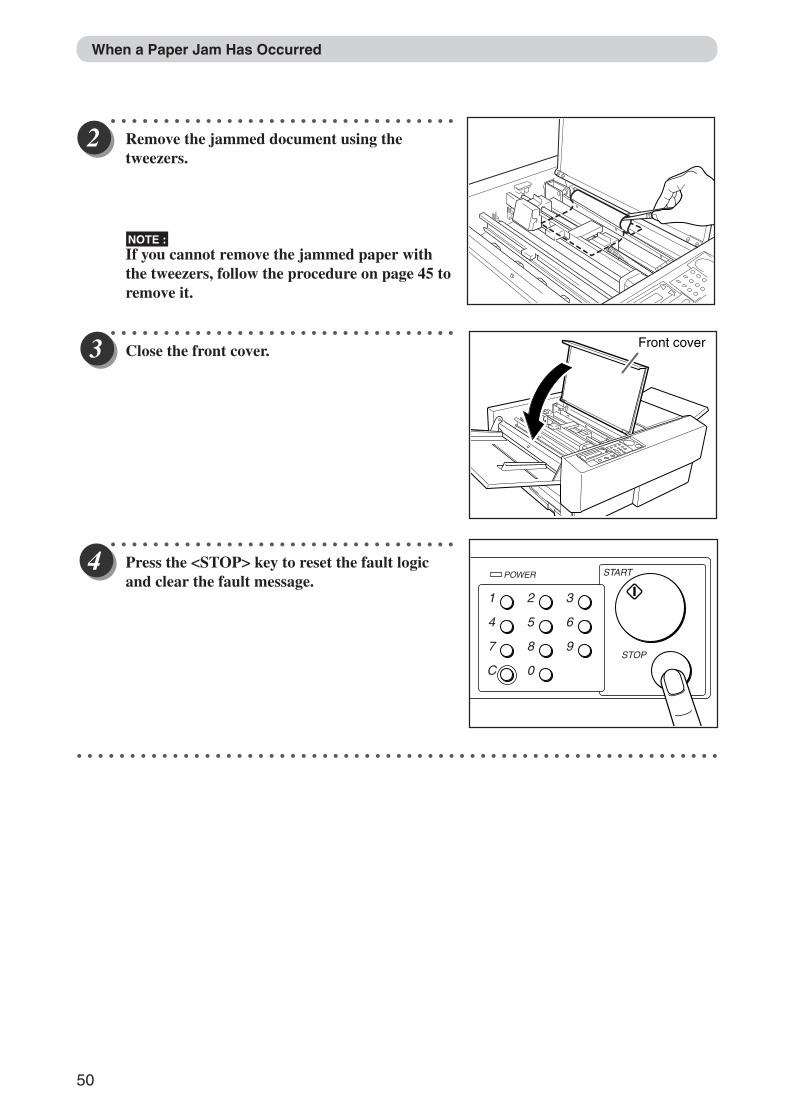
○ ○ ○ ○ ○ ○ ○ ○ ○ ○ ○ ○ ○ ○ ○ ○ ○ ○ ○ ○ ○ ○ ○ ○ ○ ○ ○ ○ ○ ○ ○ ○ ○
Remove the jammed document using thetweezers.
NOTE :If you cannot remove the jammed paper withthe tweezers, follow the procedure on page 45 toremove it.
○ ○ ○ ○ ○ ○ ○ ○ ○ ○ ○ ○ ○ ○ ○ ○ ○ ○ ○ ○ ○ ○ ○ ○ ○ ○ ○ ○ ○ ○ ○ ○ ○
Close the front cover.
○ ○ ○ ○ ○ ○ ○ ○ ○ ○ ○ ○ ○ ○ ○ ○ ○ ○ ○ ○ ○ ○ ○ ○ ○ ○ ○ ○ ○ ○ ○ ○ ○
Press the <STOP> key to reset the fault logicand clear the fault message.
○ ○ ○ ○ ○ ○ ○ ○ ○ ○ ○ ○ ○ ○ ○ ○ ○ ○ ○ ○ ○ ○ ○ ○ ○ ○ ○ ○ ○ ○ ○ ○ ○ ○ ○ ○ ○ ○ ○ ○ ○ ○ ○ ○ ○ ○ ○ ○ ○ ○ ○ ○ ○ ○ ○ ○ ○ ○ ○ ○ ○
When a Paper Jam Has Occurred
Front cover
1
4
7
C
2
5
8
0
3
6
9
POWER START
STOP
Docu Cutter(HCEX) 4_30-52 03.12.8, 3:10 PM50
51
6
2
1
4
Troubleshooting - DC
545 HC
EX
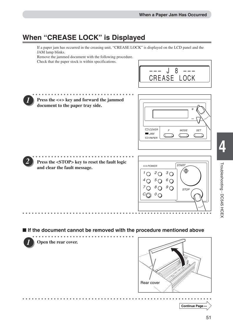
When “CREASE LOCK” is DisplayedIf a paper jam has occurred in the creasing unit, “CREASE LOCK” is displayed on the LCD panel and theJAM lamp blinks.Remove the jammed document with the following procedure.Check that the paper stock is within specifications.
○ ○ ○ ○ ○ ○ ○ ○ ○ ○ ○ ○ ○ ○ ○ ○ ○ ○ ○ ○ ○ ○ ○ ○ ○ ○ ○ ○ ○ ○ ○ ○ ○
Press the <+> key and forward the jammeddocument to the paper tray side.
○ ○ ○ ○ ○ ○ ○ ○ ○ ○ ○ ○ ○ ○ ○ ○ ○ ○ ○ ○ ○ ○ ○ ○ ○ ○ ○ ○ ○ ○ ○ ○ ○
Press the <STOP> key to reset the fault logicand clear the fault message.
○ ○ ○ ○ ○ ○ ○ ○ ○ ○ ○ ○ ○ ○ ○ ○ ○ ○ ○ ○ ○ ○ ○ ○ ○ ○ ○ ○ ○ ○ ○ ○ ○ ○ ○ ○ ○ ○ ○ ○ ○ ○ ○ ○ ○ ○ ○ ○ ○ ○ ○ ○ ○ ○ ○ ○ ○ ○ ○ ○ ○
� If the document cannot be removed with the procedure mentioned above○ ○ ○ ○ ○ ○ ○ ○ ○ ○ ○ ○ ○ ○ ○ ○ ○ ○ ○ ○ ○ ○ ○ ○ ○ ○ ○ ○ ○ ○ ○ ○ ○
Open the rear cover.
○ ○ ○ ○ ○ ○ ○ ○ ○ ○ ○ ○ ○ ○ ○ ○ ○ ○ ○ ○ ○ ○ ○ ○ ○ ○ ○ ○ ○ ○ ○ ○ ○ ○ ○ ○ ○ ○ ○ ○ ○ ○ ○ ○ ○ ○ ○ ○ ○ ○ ○ ○ ○ ○ ○ ○ ○ ○ ○ ○ ○
Rear cover
––– J 8 ––– CREASE LOCK
When a Paper Jam Has Occurred
COVER
JAMF
PAPER
MODE SET
+
–
1
4
7
C
2
5
8
0
3
6
9
POWER START
STOP
Continue Page •••
Docu Cutter(HCEX) 4_30-52 03.12.8, 3:10 PM51
52
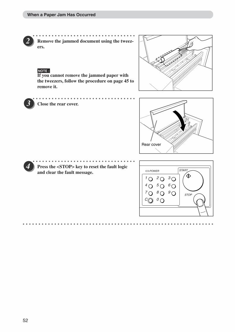
○ ○ ○ ○ ○ ○ ○ ○ ○ ○ ○ ○ ○ ○ ○ ○ ○ ○ ○ ○ ○ ○ ○ ○ ○ ○ ○ ○ ○ ○ ○ ○ ○
Remove the jammed document using the tweez-ers.
NOTE :If you cannot remove the jammed paper withthe tweezers, follow the procedure on page 45 toremove it.
○ ○ ○ ○ ○ ○ ○ ○ ○ ○ ○ ○ ○ ○ ○ ○ ○ ○ ○ ○ ○ ○ ○ ○ ○ ○ ○ ○ ○ ○ ○ ○ ○
Close the rear cover.
○ ○ ○ ○ ○ ○ ○ ○ ○ ○ ○ ○ ○ ○ ○ ○ ○ ○ ○ ○ ○ ○ ○ ○ ○ ○ ○ ○ ○ ○ ○ ○ ○
Press the <STOP> key to reset the fault logicand clear the fault message.
○ ○ ○ ○ ○ ○ ○ ○ ○ ○ ○ ○ ○ ○ ○ ○ ○ ○ ○ ○ ○ ○ ○ ○ ○ ○ ○ ○ ○ ○ ○ ○ ○ ○ ○ ○ ○ ○ ○ ○ ○ ○ ○ ○ ○ ○ ○ ○ ○ ○ ○ ○ ○ ○ ○ ○ ○ ○ ○ ○ ○
Rear cover
1
4
7
C
2
5
8
0
3
6
9
POWER START
STOP
When a Paper Jam Has Occurred
Docu Cutter(HCEX) 4_30-52 03.12.8, 3:11 PM52
53
1
5
Manual P
rogramm
ing - DC
545 HC
EX
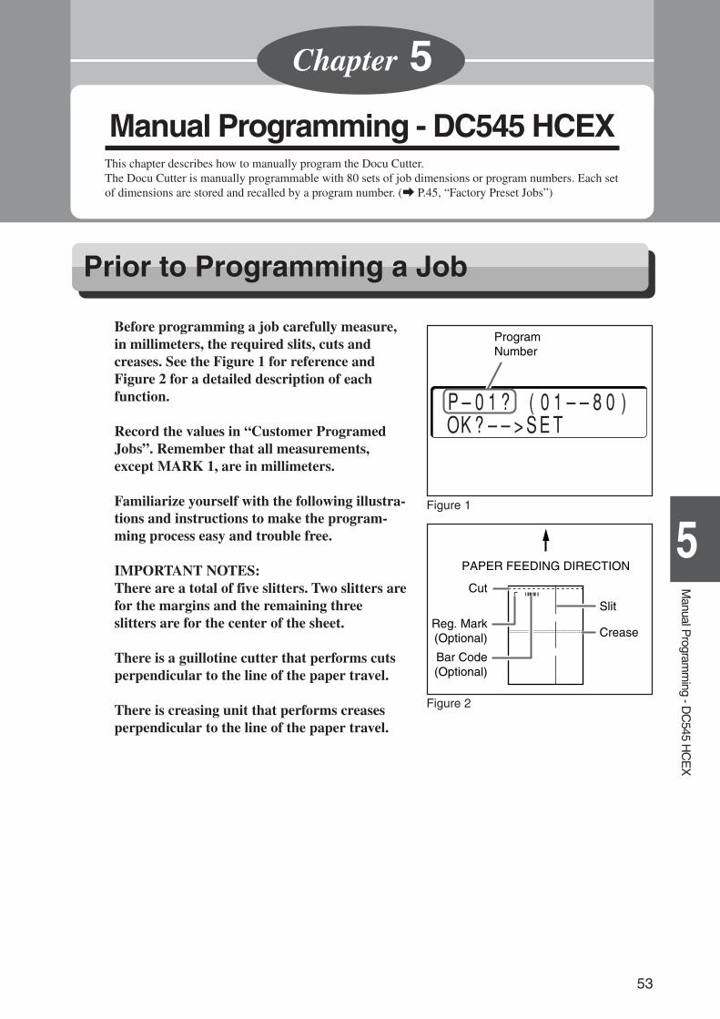
Before programming a job carefully measure,in millimeters, the required slits, cuts andcreases. See the Figure 1 for reference andFigure 2 for a detailed description of eachfunction.
Record the values in “Customer ProgramedJobs”. Remember that all measurements,except MARK 1, are in millimeters.
Familiarize yourself with the following illustra-tions and instructions to make the program-ming process easy and trouble free.
IMPORTANT NOTES:There are a total of five slitters. Two slitters arefor the margins and the remaining threeslitters are for the center of the sheet.
There is a guillotine cutter that performs cutsperpendicular to the line of the paper travel.
There is creasing unit that performs creasesperpendicular to the line of the paper travel.
PAPER FEEDING DIRECTION
Slit
Cut
Reg. Mark(Optional)
Bar Code(Optional)
Crease
Manual Programming - DC545 HCEXThis chapter describes how to manually program the Docu Cutter.The Docu Cutter is manually programmable with 80 sets of job dimensions or program numbers. Each setof dimensions are stored and recalled by a program number. (a P.45, “Factory Preset Jobs”)
Chapter 5
Prior to Programming a Job
P–01? (01––80) OK?––>SET
ProgramNumber
Figure 2
Figure 1
Docu Cutter(HCEX) 5_53-69 03.12.8, 3:11 PM53
54
Definition of Programming Terms
Tip
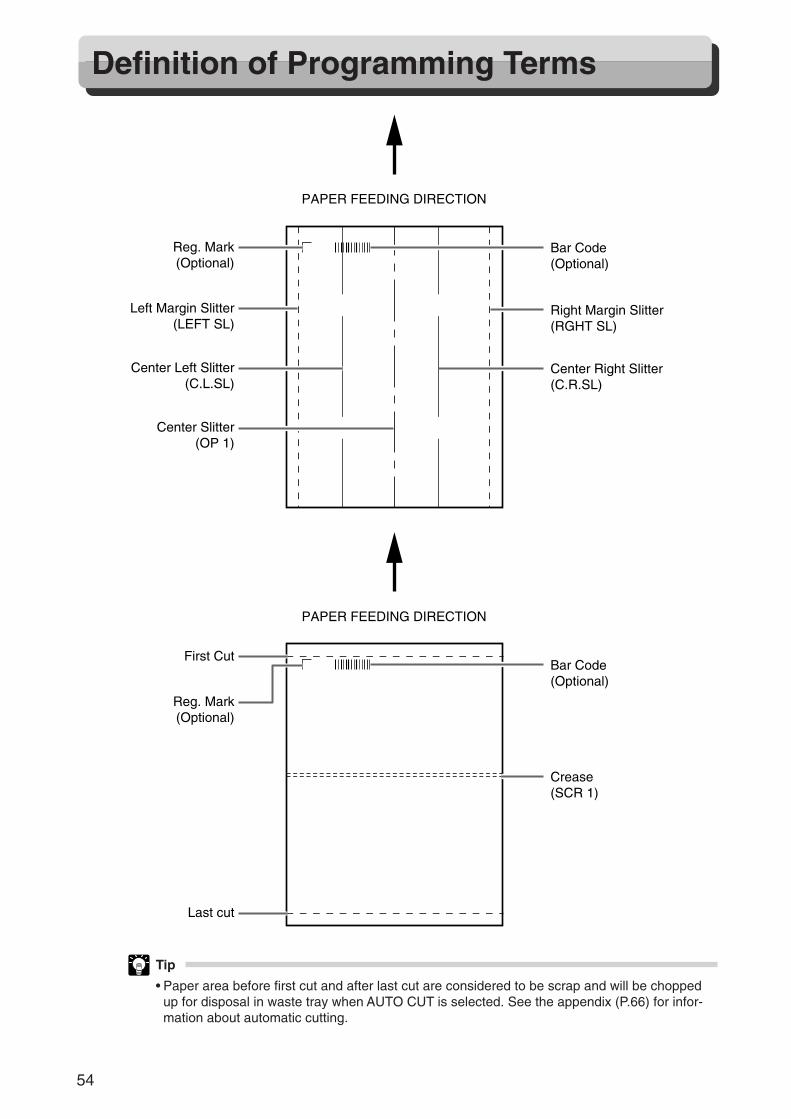
• Paper area before first cut and after last cut are considered to be scrap and will be choppedup for disposal in waste tray when AUTO CUT is selected. See the appendix (P.66) for infor-mation about automatic cutting.
PAPER FEEDING DIRECTION
PAPER FEEDING DIRECTION
Reg. Mark(Optional)
First Cut
Last cut
Bar Code(Optional)
Crease(SCR 1)
Reg. Mark(Optional)
Left Margin Slitter(LEFT SL)
Center Left Slitter(C.L.SL)
Center Slitter(OP 1)
Bar Code(Optional)
Right Margin Slitter(RGHT SL)
Center Right Slitter(C.R.SL)
Docu Cutter(HCEX) 5_53-69 03.12.8, 3:11 PM54
55
1
5
Manual P
rogramm
ing - DC
545 HC
EX
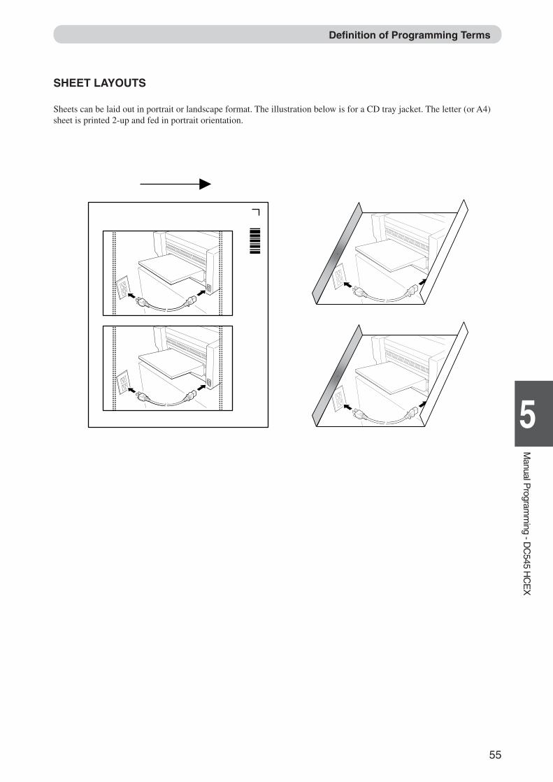
SHEET LAYOUTS
Sheets can be laid out in portrait or landscape format. The illustration below is for a CD tray jacket. The letter (or A4)sheet is printed 2-up and fed in portrait orientation.
Definition of Programming Terms
Docu Cutter(HCEX) 5_53-69 03.12.8, 3:11 PM55
56
AUTO CUT
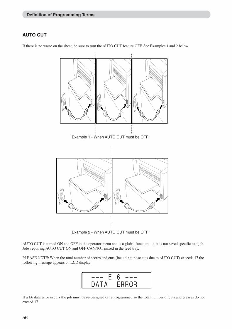
If there is no waste on the sheet, be sure to turn the AUTO CUT feature OFF. See Examples 1 and 2 below.
Definition of Programming Terms
AUTO CUT is turned ON and OFF in the operator menu and is a global function, i.e. it is not saved specific to a job.Jobs requiring AUTO CUT ON and OFF CANNOT mixed in the feed tray.
PLEASE NOTE: When the total number of scores and cuts (including those cuts due to AUTO CUT) exceeds 17 thefollowing message appears on LCD display:
––– E 6 ––– DATA ERROR
If a E6 data error occurs the job must be re-designed or reprogrammed so the total number of cuts and creases do notexceed 17
Example 1 - When AUTO CUT must be OFF
Example 2 - When AUTO CUT must be OFF
Docu Cutter(HCEX) 5_53-69 03.12.8, 3:11 PM56
57
1
5
Manual P
rogramm
ing - DC
545 HC
EX
JOB DESIGN ISSUES
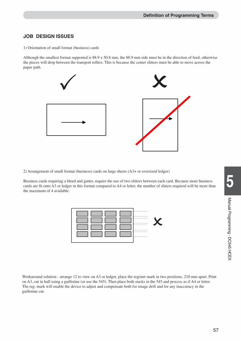
1) Orientation of small format (business) cards
Although the smallest format supported is 88.9 x 50.8 mm, the 88.9 mm side must be in the direction of feed, otherwisethe pieces will drop between the transport rollers. This is because the center slitters must be able to move across thepaper path.
Definition of Programming Terms
2) Arrangement of small format (business) cards on large sheets (A3+ or oversized ledger)
Business cards requiring a bleed and gutter, require the use of two slitters between each card. Because more businesscards are fit onto A3 or ledger in this format compared to A4 or letter, the number of slitters required will be more thanthe maximum of 4 available.
Workaround solution - arrange 12 to view on A3 or ledger, place the register mark in two positions, 210 mm apart. Printon A3, cut in half using a guillotine (or use the 545). Then place both stacks in the 545 and process as if A4 or letter.The reg. mark will enable the device to adjust and compensate both for image drift and for any inaccuracy in theguillotine cut.
Docu Cutter(HCEX) 5_53-69 03.12.8, 3:11 PM57
58
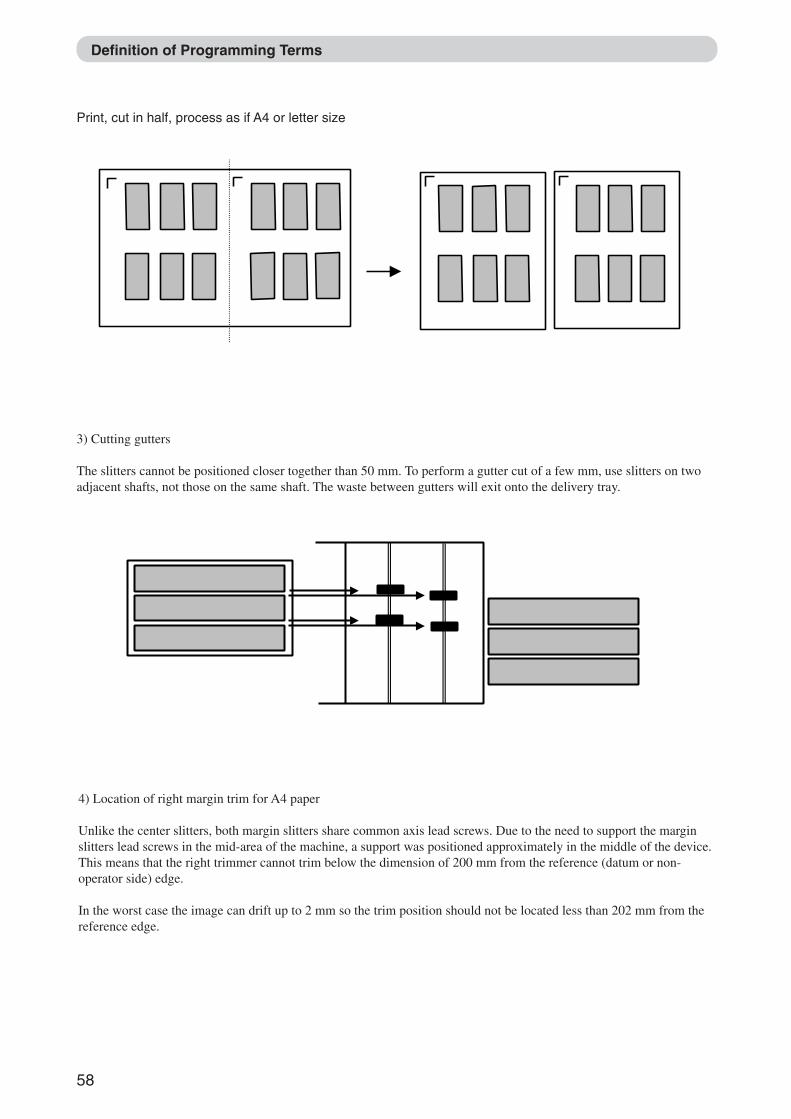
Print, cut in half, process as if A4 or letter size
Definition of Programming Terms
3) Cutting gutters
The slitters cannot be positioned closer together than 50 mm. To perform a gutter cut of a few mm, use slitters on twoadjacent shafts, not those on the same shaft. The waste between gutters will exit onto the delivery tray.
4) Location of right margin trim for A4 paper
Unlike the center slitters, both margin slitters share common axis lead screws. Due to the need to support the marginslitters lead screws in the mid-area of the machine, a support was positioned approximately in the middle of the device.This means that the right trimmer cannot trim below the dimension of 200 mm from the reference (datum or non-operator side) edge.
In the worst case the image can drift up to 2 mm so the trim position should not be located less than 202 mm from thereference edge.
Docu Cutter(HCEX) 5_53-69 03.12.8, 3:11 PM58
59
1
5
Manual P
rogramm
ing - DC
545 HC
EX
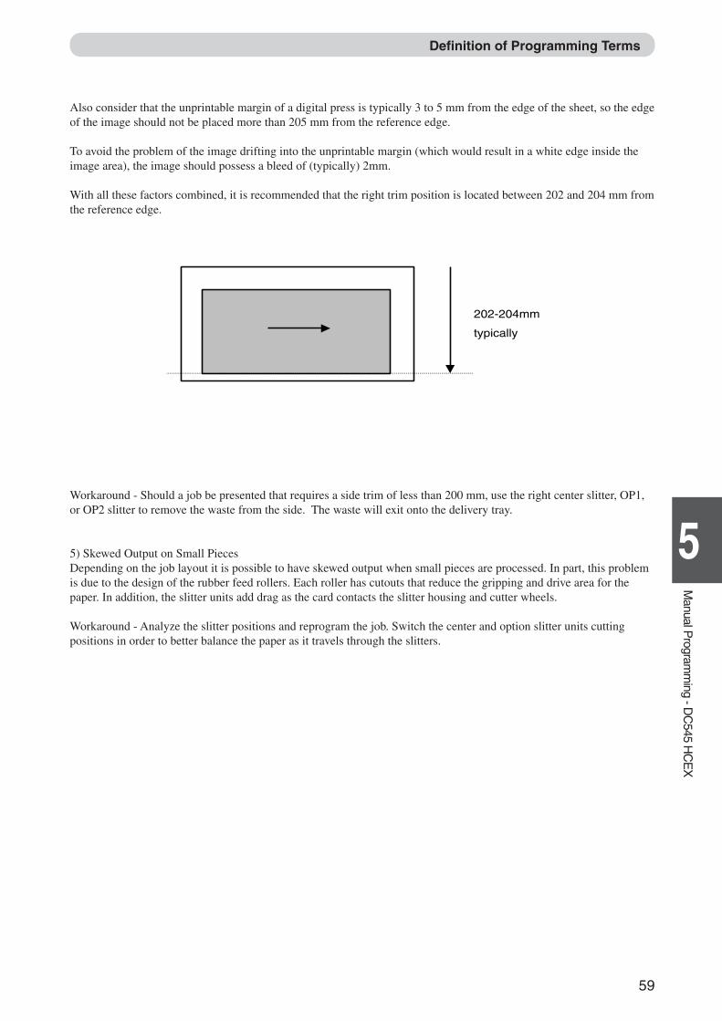
Also consider that the unprintable margin of a digital press is typically 3 to 5 mm from the edge of the sheet, so the edgeof the image should not be placed more than 205 mm from the reference edge.
To avoid the problem of the image drifting into the unprintable margin (which would result in a white edge inside theimage area), the image should possess a bleed of (typically) 2mm.
With all these factors combined, it is recommended that the right trim position is located between 202 and 204 mm fromthe reference edge.
Definition of Programming Terms
202-204mm
typically
Workaround - Should a job be presented that requires a side trim of less than 200 mm, use the right center slitter, OP1,or OP2 slitter to remove the waste from the side. The waste will exit onto the delivery tray.
5) Skewed Output on Small PiecesDepending on the job layout it is possible to have skewed output when small pieces are processed. In part, this problemis due to the design of the rubber feed rollers. Each roller has cutouts that reduce the gripping and drive area for thepaper. In addition, the slitter units add drag as the card contacts the slitter housing and cutter wheels.
Workaround - Analyze the slitter positions and reprogram the job. Switch the center and option slitter units cuttingpositions in order to better balance the paper as it travels through the slitters.
Docu Cutter(HCEX) 5_53-69 03.12.8, 3:11 PM59
60
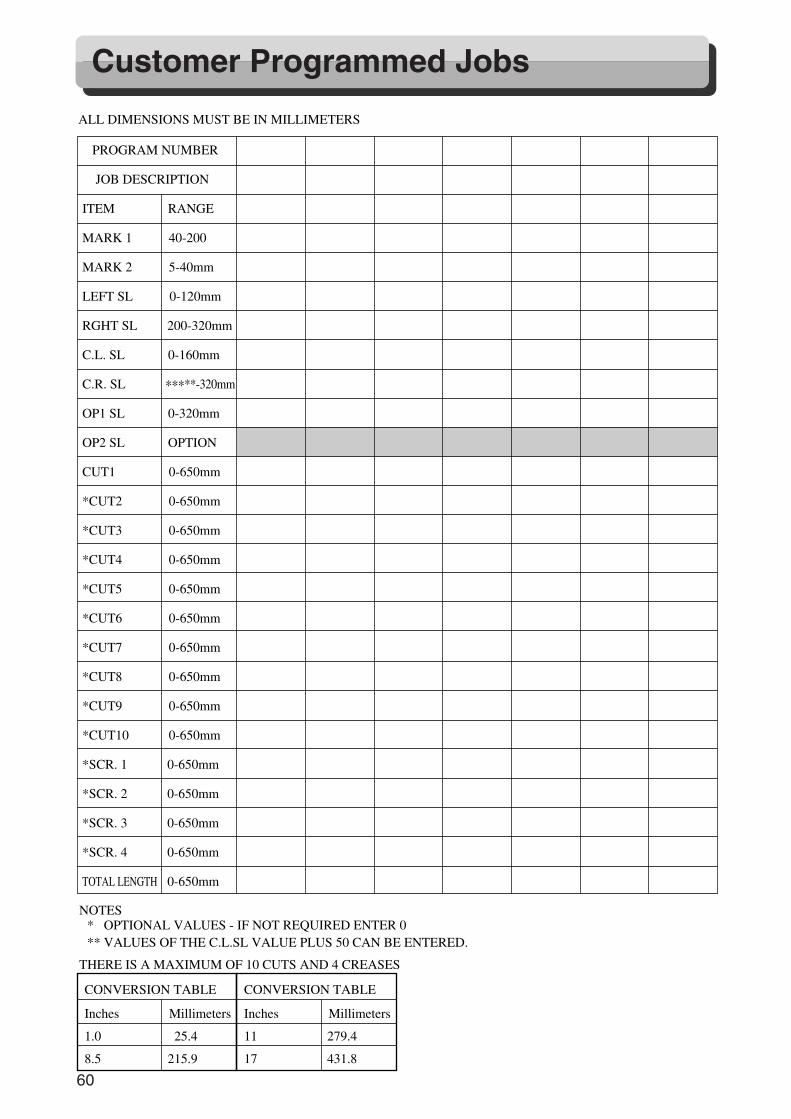
Customer Programmed Jobs
PROGRAM NUMBER
JOB DESCRIPTION
ITEM RANGE
MARK 1 40-200
MARK 2 5-40mm
LEFT SL 0-120mm
RGHT SL 200-320mm
C.L. SL 0-160mm
C.R. SL ∗∗∗**-320mm
OP1 SL 0-320mm
OP2 SL OPTION
CUT1 0-650mm
*CUT2 0-650mm
*CUT3 0-650mm
*CUT4 0-650mm
*CUT5 0-650mm
*CUT6 0-650mm
*CUT7 0-650mm
*CUT8 0-650mm
*CUT9 0-650mm
*CUT10 0-650mm
*SCR. 1 0-650mm
*SCR. 2 0-650mm
*SCR. 3 0-650mm
*SCR. 4 0-650mm
TOTAL LENGTH 0-650mm
NOTES
ALL DIMENSIONS MUST BE IN MILLIMETERS
CONVERSION TABLE
Inches Millimeters
1.0 225.4
8.5 215.9
CONVERSION TABLE
Inches Millimeters
11 279.4
17 431.8
** OPTIONAL VALUES - IF NOT REQUIRED ENTER 0** VALUES OF THE C.L.SL VALUE PLUS 50 CAN BE ENTERED.
THERE IS A MAXIMUM OF 10 CUTS AND 4 CREASES
Docu Cutter(HCEX) 5_53-69 03.12.8, 3:11 PM60
61
1
5
Manual P
rogramm
ing - DC
545 HC
EX
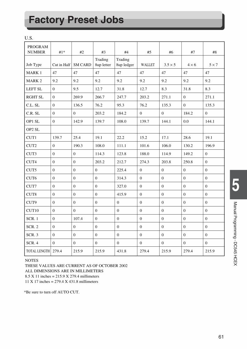
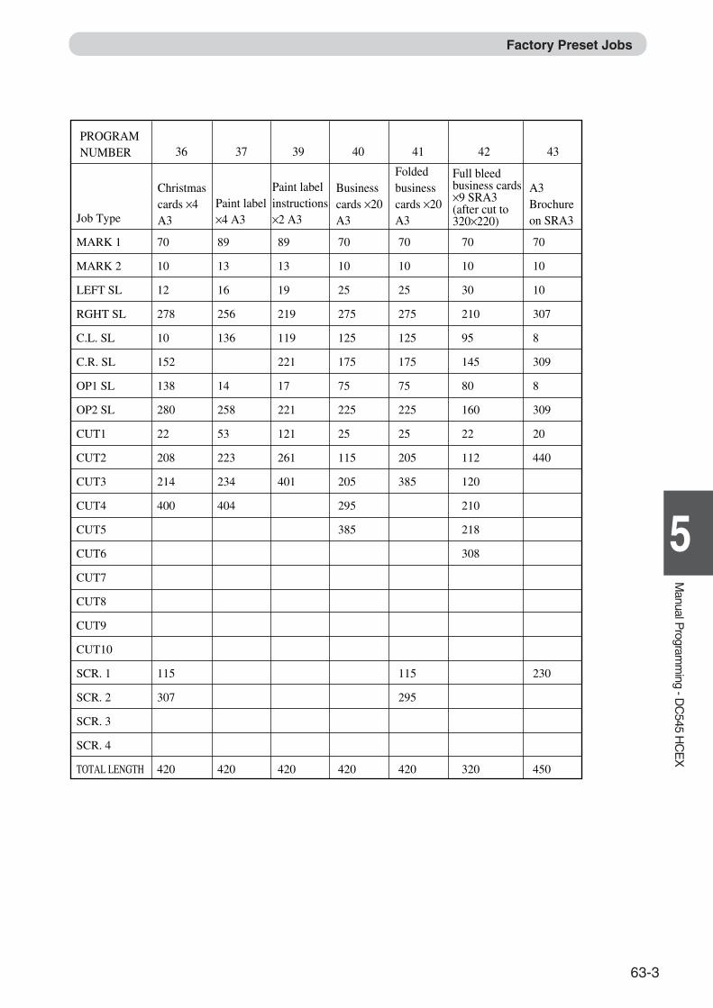
Factory Preset Jobs
Job Type
MARK 1
MARK 2
LEFT SL
RGHT SL
C.L. SL
C.R. SL
OP1 SL
OP2 SL
CUT1
CUT2
CUT3
CUT4
CUT5
CUT6
CUT7
CUT8
CUT9
CUT10
SCR. 1
SCR. 2
SCR. 3
SCR. 4
TOTAL LENGTH
SM CARDTrading 8up letter
Trading8up ledger WALLET 3.5 × 5 4 × 6 5 × 7
PROGRAM NUMBER #1* #2 #3 #4 #5 #6 #7 #8
47 47 47 47 47 47 47 47
9.2 9.2 9.2 9.2 9.2 9.2 9.2 9.2
0 9.5 12.7 31.8 12.7 8.3 31.8 8.3
0 269.9 266.7 247.7 203.2 271.1 0 271.1
0 136.5 76.2 95.3 76.2 135.3 0 135.3
0 0 203.2 184.2 0 0 184.2 0
0 142.9 139.7 108.0 139.7 144.1 0.0 144.1
139.7 25.4 19.1 22.2 15.2 17.1 28.6 19.1
0 190.3 108.0 111.1 101.6 106.0 130.2 196.9
0 0 114.3 123.8 188.0 114.9 149.2 0
0 0 203.2 212.7 274.3 203.8 250.8 0
0 0 0 225.4 0 0 0 0
0 0 0 314.3 0 0 0 0
0 0 0 327.0 0 0 0 0
0 0 0 415.9 0 0 0 0
0 0 0 0 0 0 0 0
0 0 0 0 0 0 0 0
0 107.4 0 0 0 0 0 0
0 0 0 0 0 0 0 0
0 0 0 0 0 0 0 0
0 0 0 0 0 0 0 0
279.4 215.9 215.9 431.8 279.4 215.9 279.4 215.9
NOTESTHESE VALUES ARE CURRENT AS OF OCTOBER 2002ALL DIMENSIONS ARE IN MILLIMETERS8.5 X 11 inches = 215.9 X 279.4 millimeters 11 X 17 inches = 279.4 X 431.8 millimeters
*Be sure to turn off AUTO CUT.
Cut in Half
U.S.
Docu Cutter(HCEX) 5_53-69 03.12.8, 3:11 PM61
62
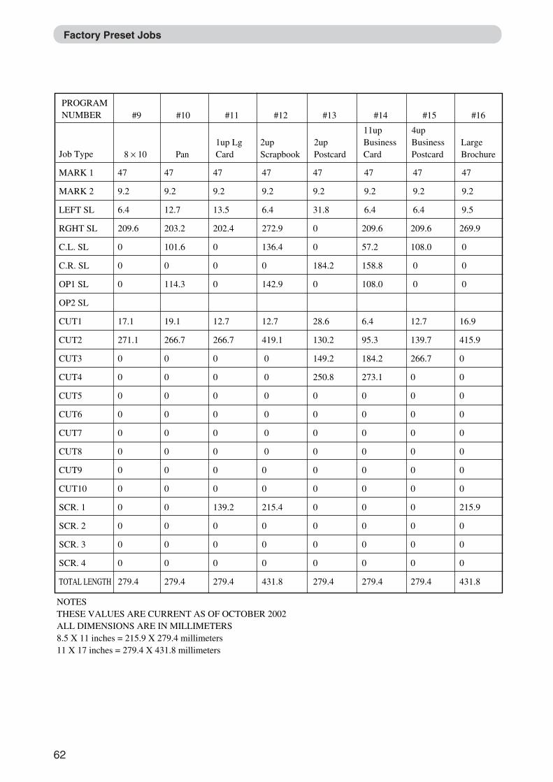
Job Type
MARK 1
MARK 2
LEFT SL
RGHT SL
C.L. SL
C.R. SL
OP1 SL
OP2 SL
CUT1
CUT2
CUT3
CUT4
CUT5
CUT6
CUT7
CUT8
CUT9
CUT10
SCR. 1
SCR. 2
SCR. 3
SCR. 4
TOTAL LENGTH
Pan8 × 101up Lg Card
2up Scrapbook
2up Postcard
11up Business Card
4up Business Postcard
Large Brochure
PROGRAM NUMBER #9 #10 #11 #12 #13 #14 #15 #16
47 47 47 47 47 47 47 47
9.2 9.2 9.2 9.2 9.2 9.2 9.2 9.2
6.4 12.7 13.5 6.4 31.8 6.4 6.4 9.5
209.6 203.2 202.4 272.9 0 209.6 209.6 269.9
0 101.6 0 136.4 0 57.2 108.0 0
0 0 0 0 184.2 158.8 0 0
0 114.3 0 142.9 0 108.0 0 0
17.1 19.1 12.7 12.7 28.6 6.4 12.7 16.9
271.1 266.7 266.7 419.1 130.2 95.3 139.7 415.9
0 0 0 0 149.2 184.2 266.7 0
0 0 0 0 250.8 273.1 0 0
0 0 0 0 0 0 0 0
0 0 0 0 0 0 0 0
0 0 0 0 0 0 0 0
0 0 0 0 0 0 0 0
0 0 0 0 0 0 0 0
0 0 0 0 0 0 0 0
0 0 139.2 215.4 0 0 0 215.9
0 0 0 0 0 0 0 0
0 0 0 0 0 0 0 0
0 0 0 0 0 0 0 0
279.4 279.4 279.4 431.8 279.4 279.4 279.4 431.8
NOTESTHESE VALUES ARE CURRENT AS OF OCTOBER 2002ALL DIMENSIONS ARE IN MILLIMETERS8.5 X 11 inches = 215.9 X 279.4 millimeters
11 X 17 inches = 279.4 X 431.8 millimeters
Factory Preset Jobs
Docu Cutter(HCEX) 5_53-69 03.12.8, 3:11 PM62
63
1
5
Manual P
rogramm
ing - DC
545 HC
EX
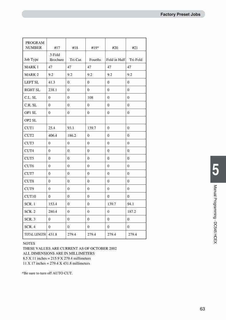
Job Type
MARK 1
MARK 2
LEFT SL
RGHT SL
C.L. SL
C.R. SL
OP1 SL
OP2 SL
CUT1
CUT2
CUT3
CUT4
CUT5
CUT6
CUT7
CUT8
CUT9
CUT10
SCR. 1
SCR. 2
SCR. 3
SCR. 4
TOTAL LENGTH
3-FoldBrochure Fold in Half Tri-Fold
PROGRAM NUMBER #17 #18 #19* #20 #21
47 47 47 47 47
9.2 9.2 9.2 9.2 9.2
41.3 0 0 0 0
238.1 0 0 0 0
0 0 108 0 0
0 0 0 0 0
0 0 0 0 0
25.4 93.1 139.7 0 0
406.4 186.2 0 0 0
0 0 0 0 0
0 0 0 0 0
0 0 0 0 0
0 0 0 0 0
0 0 0 0 0
0 0 0 0 0
0 0 0 0 0
0 0 0 0 0
153.4 0 0 139.7 94.1
280.4 0 0 0 187.2
0 0 0 0 0
0 0 0 0 0
431.8 279.4 279.4 279.4 279.4
NOTESTHESE VALUES ARE CURRENT AS OF OCTOBER 2002ALL DIMENSIONS ARE IN MILLIMETERS8.5 X 11 inches = 215.9 X 279.4 millimeters
11 X 17 inches = 279.4 X 431.8 millimeters
*Be sure to turn off AUTO CUT.
Tri-Cut Fourths
Factory Preset Jobs
Docu Cutter(HCEX) 5_53-69 03.12.8, 3:11 PM63
62
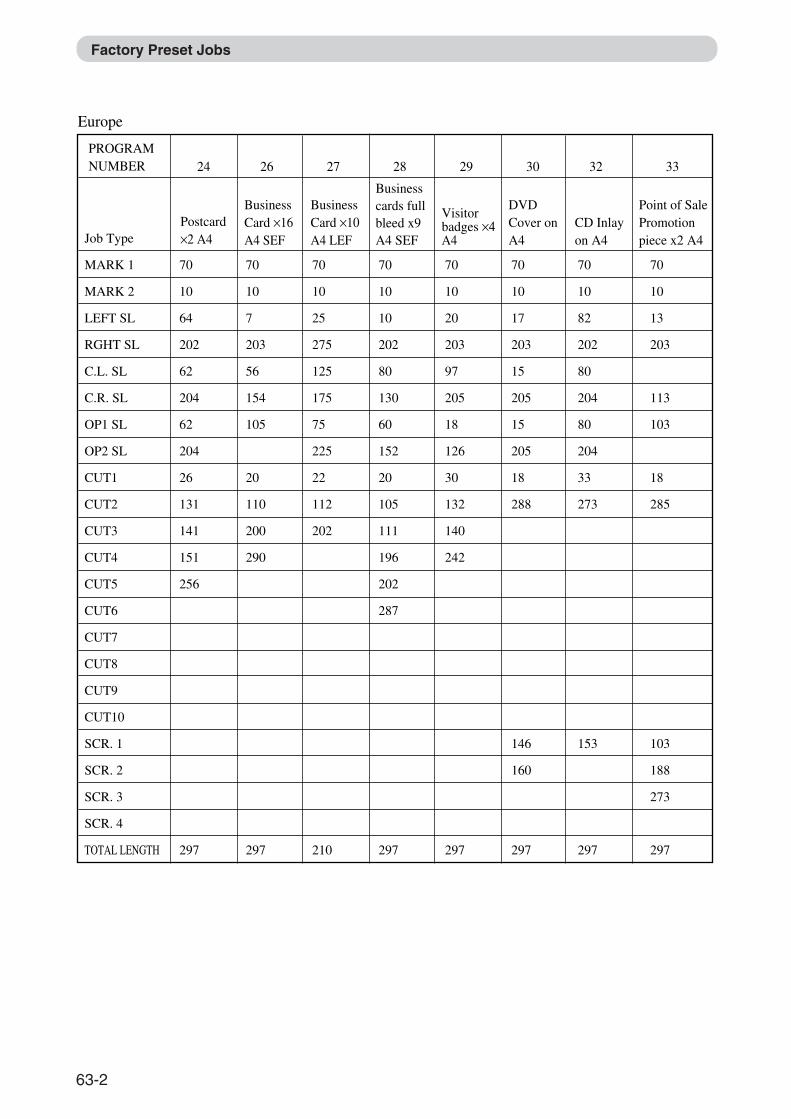
Job Type
MARK 1
MARK 2
LEFT SL
RGHT SL
C.L. SL
C.R. SL
OP1 SL
OP2 SL
CUT1
CUT2
CUT3
CUT4
CUT5
CUT6
CUT7
CUT8
CUT9
CUT10
SCR. 1
SCR. 2
SCR. 3
SCR. 4
TOTAL LENGTH
Business Card ×16A4 SEF
Postcard×2 A4
DVD Cover on A4
CD Inlay on A4
PROGRAM NUMBER
Europe
24 26 27 28 29 30 32 33
70
10
64
202
62
204
62
204
26
131
141
151
256
297
70
10
7
203
56
154
105
20
110
200
290
297
70
10
25
275
125
175
75
225
22
112
202
210
70
10
10
202
80
130
60
152
20
105
111
196
202
287
297
70
10
20
203
97
205
18
126
30
132
140
242
297
70
10
17
203
15
205
15
205
18
288
146
160
297
70
10
82
202
80
204
80
204
33
273
153
297
70
10
13
203
113
103
18
285
103
188
273
297
Business Card ×10A4 LEF
Visitor badges ×4A4
Business cards full bleed x9 A4 SEF
Point of Sale Promotion piece x2 A4
Factory Preset Jobs
63-2
63
1
5
Manual P
rogramm
ing - DC
545 HC
EX
Job Type
MARK 1
MARK 2
LEFT SL
RGHT SL
C.L. SL
C.R. SL
OP1 SL
OP2 SL
CUT1
CUT2
CUT3
CUT4
CUT5
CUT6
CUT7
CUT8
CUT9
CUT10
SCR. 1
SCR. 2
SCR. 3
SCR. 4
TOTAL LENGTH
Christmas cards ×4 A3
Business cards ×20 A3
Folded business cards ×20 A3
PROGRAM NUMBER 36 37 39 40 41 42 43
70
10
12
278
10
152
138
280
22
208
214
400
115
307
420
89
13
16
256
136
14
258
53
223
234
404
420
89
13
19
219
119
221
17
221
121
261
401
420
70
10
25
275
125
175
75
225
25
115
205
295
385
420
70
10
25
275
125
175
75
225
25
205
385
115
295
420
70
10
30
210
95
145
80
160
22
112
120
210
218
308
320
70
10
10
307
8
309
8
309
20
440
230
450
Paint label ×4 A3
Paint label instructions ×2 A3
Full bleed business cards ×9 SRA3 (after cut to 320×220)
A3 Brochure on SRA3
Factory Preset Jobs
63-3
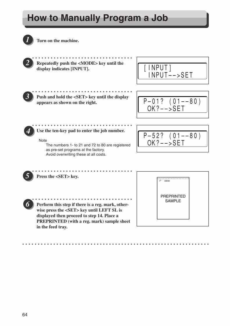
64
○ ○ ○ ○ ○ ○ ○ ○ ○ ○ ○ ○ ○ ○ ○ ○ ○ ○ ○ ○ ○ ○ ○ ○ ○ ○ ○ ○ ○ ○ ○ ○ ○ ○ ○ ○ ○ ○ ○ ○ ○ ○ ○ ○ ○ ○ ○ ○ ○ ○ ○ ○ ○ ○ ○ ○ ○ ○
Turn on the machine.
○ ○ ○ ○ ○ ○ ○ ○ ○ ○ ○ ○ ○ ○ ○ ○ ○ ○ ○ ○ ○ ○ ○ ○ ○ ○ ○ ○ ○ ○ ○ ○ ○
Repeatedly push the <MODE> key until thedisplay indicates [INPUT].
○ ○ ○ ○ ○ ○ ○ ○ ○ ○ ○ ○ ○ ○ ○ ○ ○ ○ ○ ○ ○ ○ ○ ○ ○ ○ ○ ○ ○ ○ ○ ○ ○
Push and hold the <SET> key until the displayappears as shown on the right.
○ ○ ○ ○ ○ ○ ○ ○ ○ ○ ○ ○ ○ ○ ○ ○ ○ ○ ○ ○ ○ ○ ○ ○ ○ ○ ○ ○ ○ ○ ○ ○ ○
Use the ten-key pad to enter the job number.
NoteThe numbers 1- to 21 and 72 to 80 are registeredas pre-set programs at the factory.Avoid overwriting these at all costs.
○ ○ ○ ○ ○ ○ ○ ○ ○ ○ ○ ○ ○ ○ ○ ○ ○ ○ ○ ○ ○ ○ ○ ○ ○ ○ ○ ○ ○ ○ ○ ○ ○
Press the <SET> key.
○ ○ ○ ○ ○ ○ ○ ○ ○ ○ ○ ○ ○ ○ ○ ○ ○ ○ ○ ○ ○ ○ ○ ○ ○ ○ ○ ○ ○ ○ ○ ○ ○
Perform this step if there is a reg. mark, other-wise press the <SET> key until LEFT SL isdisplayed then proceed to step 14. Place aPREPRINTED (with a reg. mark) sample sheetin the feed tray.
○ ○ ○ ○ ○ ○ ○ ○ ○ ○ ○ ○ ○ ○ ○ ○ ○ ○ ○ ○ ○ ○ ○ ○ ○ ○ ○ ○ ○ ○ ○ ○ ○ ○ ○ ○ ○ ○ ○ ○ ○ ○ ○ ○ ○ ○ ○ ○ ○ ○ ○ ○ ○ ○ ○ ○ ○ ○ ○ ○ ○
PREPRINTEDSAMPLE
[INPUT] INPUT––>SET
P–01? (01––80) OK?––>SET
P–52? (01––80) OK?––>SET
How to Manually Program a Job
Docu Cutter(HCEX) 5_53-69 03.12.8, 3:11 PM64
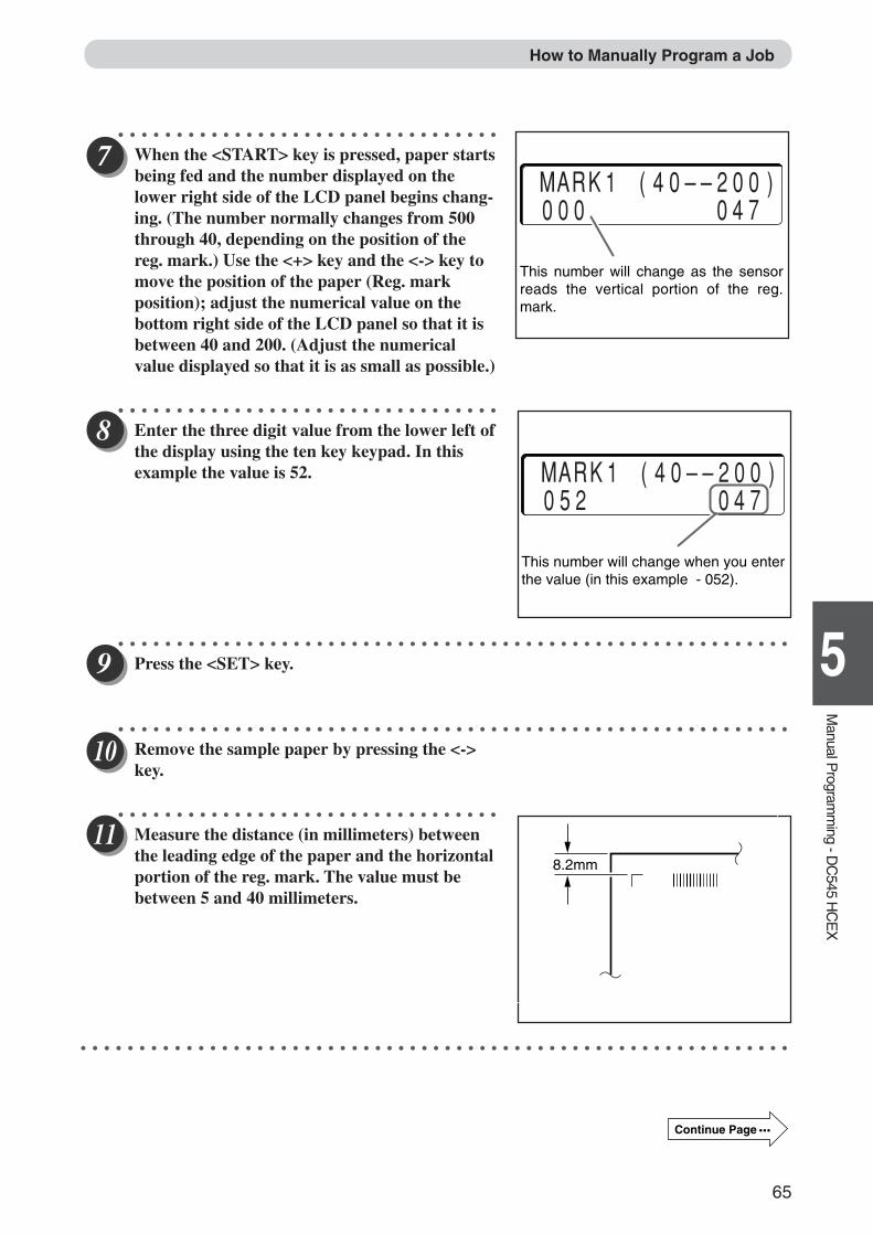
65
1
5
Manual P
rogramm
ing - DC
545 HC
EX
○ ○ ○ ○ ○ ○ ○ ○ ○ ○ ○ ○ ○ ○ ○ ○ ○ ○ ○ ○ ○ ○ ○ ○ ○ ○ ○ ○ ○ ○ ○ ○ ○
When the <START> key is pressed, paper startsbeing fed and the number displayed on thelower right side of the LCD panel begins chang-ing. (The number normally changes from 500through 40, depending on the position of thereg. mark.) Use the <+> key and the <-> key tomove the position of the paper (Reg. markposition); adjust the numerical value on thebottom right side of the LCD panel so that it isbetween 40 and 200. (Adjust the numericalvalue displayed so that it is as small as possible.)
○ ○ ○ ○ ○ ○ ○ ○ ○ ○ ○ ○ ○ ○ ○ ○ ○ ○ ○ ○ ○ ○ ○ ○ ○ ○ ○ ○ ○ ○ ○ ○ ○
Enter the three digit value from the lower left ofthe display using the ten key keypad. In thisexample the value is 52.
○ ○ ○ ○ ○ ○ ○ ○ ○ ○ ○ ○ ○ ○ ○ ○ ○ ○ ○ ○ ○ ○ ○ ○ ○ ○ ○ ○ ○ ○ ○ ○ ○ ○ ○ ○ ○ ○ ○ ○ ○ ○ ○ ○ ○ ○ ○ ○ ○ ○ ○ ○ ○ ○ ○ ○ ○ ○
Press the <SET> key.
○ ○ ○ ○ ○ ○ ○ ○ ○ ○ ○ ○ ○ ○ ○ ○ ○ ○ ○ ○ ○ ○ ○ ○ ○ ○ ○ ○ ○ ○ ○ ○ ○ ○ ○ ○ ○ ○ ○ ○ ○ ○ ○ ○ ○ ○ ○ ○ ○ ○ ○ ○ ○ ○ ○ ○ ○ ○
Remove the sample paper by pressing the <->key.
○ ○ ○ ○ ○ ○ ○ ○ ○ ○ ○ ○ ○ ○ ○ ○ ○ ○ ○ ○ ○ ○ ○ ○ ○ ○ ○ ○ ○ ○ ○ ○ ○
Measure the distance (in millimeters) betweenthe leading edge of the paper and the horizontalportion of the reg. mark. The value must bebetween 5 and 40 millimeters.
○ ○ ○ ○ ○ ○ ○ ○ ○ ○ ○ ○ ○ ○ ○ ○ ○ ○ ○ ○ ○ ○ ○ ○ ○ ○ ○ ○ ○ ○ ○ ○ ○ ○ ○ ○ ○ ○ ○ ○ ○ ○ ○ ○ ○ ○ ○ ○ ○ ○ ○ ○ ○ ○ ○ ○ ○ ○ ○ ○ ○
MARK1 (40––200) 052 047
This number will change when you enter the value (in this example - 052).
MARK1 (40––200) 000 047
This number will change as the sensor reads the vertical portion of the reg. mark.
8.2mm
How to Manually Program a Job
Continue Page •••
Docu Cutter(HCEX) 5_53-69 03.12.8, 3:11 PM65
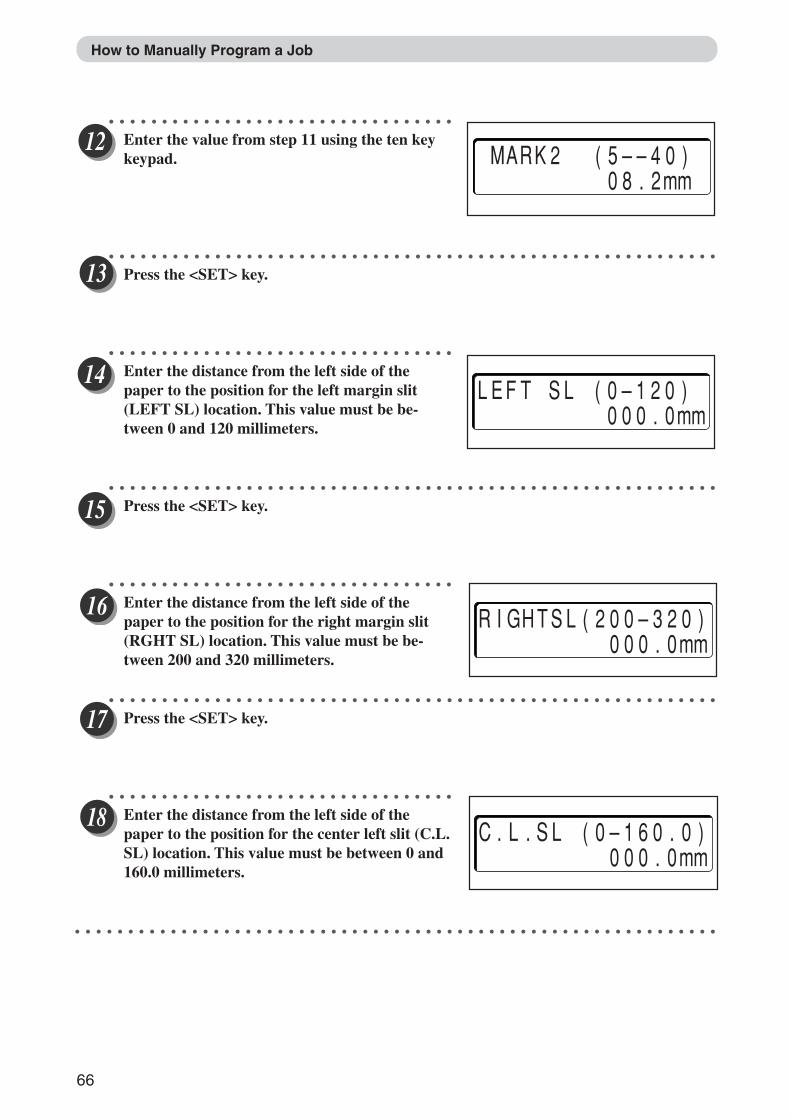
66
How to Manually Program a Job
○ ○ ○ ○ ○ ○ ○ ○ ○ ○ ○ ○ ○ ○ ○ ○ ○ ○ ○ ○ ○ ○ ○ ○ ○ ○ ○ ○ ○ ○ ○ ○ ○
Enter the value from step 11 using the ten keykeypad.
○ ○ ○ ○ ○ ○ ○ ○ ○ ○ ○ ○ ○ ○ ○ ○ ○ ○ ○ ○ ○ ○ ○ ○ ○ ○ ○ ○ ○ ○ ○ ○ ○ ○ ○ ○ ○ ○ ○ ○ ○ ○ ○ ○ ○ ○ ○ ○ ○ ○ ○ ○ ○ ○ ○ ○ ○ ○
Press the <SET> key.
○ ○ ○ ○ ○ ○ ○ ○ ○ ○ ○ ○ ○ ○ ○ ○ ○ ○ ○ ○ ○ ○ ○ ○ ○ ○ ○ ○ ○ ○ ○ ○ ○
Enter the distance from the left side of thepaper to the position for the left margin slit(LEFT SL) location. This value must be be-tween 0 and 120 millimeters.
○ ○ ○ ○ ○ ○ ○ ○ ○ ○ ○ ○ ○ ○ ○ ○ ○ ○ ○ ○ ○ ○ ○ ○ ○ ○ ○ ○ ○ ○ ○ ○ ○ ○ ○ ○ ○ ○ ○ ○ ○ ○ ○ ○ ○ ○ ○ ○ ○ ○ ○ ○ ○ ○ ○ ○ ○ ○
Press the <SET> key.
○ ○ ○ ○ ○ ○ ○ ○ ○ ○ ○ ○ ○ ○ ○ ○ ○ ○ ○ ○ ○ ○ ○ ○ ○ ○ ○ ○ ○ ○ ○ ○ ○
Enter the distance from the left side of thepaper to the position for the right margin slit(RGHT SL) location. This value must be be-tween 200 and 320 millimeters.
○ ○ ○ ○ ○ ○ ○ ○ ○ ○ ○ ○ ○ ○ ○ ○ ○ ○ ○ ○ ○ ○ ○ ○ ○ ○ ○ ○ ○ ○ ○ ○ ○ ○ ○ ○ ○ ○ ○ ○ ○ ○ ○ ○ ○ ○ ○ ○ ○ ○ ○ ○ ○ ○ ○ ○ ○ ○
Press the <SET> key.
○ ○ ○ ○ ○ ○ ○ ○ ○ ○ ○ ○ ○ ○ ○ ○ ○ ○ ○ ○ ○ ○ ○ ○ ○ ○ ○ ○ ○ ○ ○ ○ ○
Enter the distance from the left side of thepaper to the position for the center left slit (C.L.SL) location. This value must be between 0 and160.0 millimeters.
○ ○ ○ ○ ○ ○ ○ ○ ○ ○ ○ ○ ○ ○ ○ ○ ○ ○ ○ ○ ○ ○ ○ ○ ○ ○ ○ ○ ○ ○ ○ ○ ○ ○ ○ ○ ○ ○ ○ ○ ○ ○ ○ ○ ○ ○ ○ ○ ○ ○ ○ ○ ○ ○ ○ ○ ○ ○ ○ ○ ○
LEFT SL (0–120) 000.0mm
RIGHTSL(200–320) 000.0mm
C.L.SL (0–160.0) 000.0mm
MARK2 (5––40) 08.2mm
Docu Cutter(HCEX) 5_53-69 03.12.8, 3:11 PM66
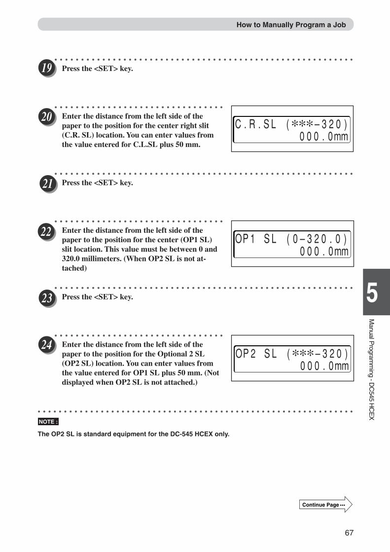
67
1
5
Manual P
rogramm
ing - DC
545 HC
EX
○ ○ ○ ○ ○ ○ ○ ○ ○ ○ ○ ○ ○ ○ ○ ○ ○ ○ ○ ○ ○ ○ ○ ○ ○ ○ ○ ○ ○ ○ ○ ○ ○ ○ ○ ○ ○ ○ ○ ○ ○ ○ ○ ○ ○ ○ ○ ○ ○ ○ ○ ○ ○ ○ ○ ○ ○
Press the <SET> key.
○ ○ ○ ○ ○ ○ ○ ○ ○ ○ ○ ○ ○ ○ ○ ○ ○ ○ ○ ○ ○ ○ ○ ○ ○ ○ ○ ○ ○ ○ ○ ○
Enter the distance from the left side of thepaper to the position for the center right slit(C.R. SL) location. You can enter values fromthe value entered for C.L.SL plus 50 mm.
○ ○ ○ ○ ○ ○ ○ ○ ○ ○ ○ ○ ○ ○ ○ ○ ○ ○ ○ ○ ○ ○ ○ ○ ○ ○ ○ ○ ○ ○ ○ ○ ○ ○ ○ ○ ○ ○ ○ ○ ○ ○ ○ ○ ○ ○ ○ ○ ○ ○ ○ ○ ○ ○ ○ ○ ○
Press the <SET> key.
○ ○ ○ ○ ○ ○ ○ ○ ○ ○ ○ ○ ○ ○ ○ ○ ○ ○ ○ ○ ○ ○ ○ ○ ○ ○ ○ ○ ○ ○ ○ ○
Enter the distance from the left side of thepaper to the position for the center (OP1 SL)slit location. This value must be between 0 and320.0 millimeters. (When OP2 SL is not at-tached)
○ ○ ○ ○ ○ ○ ○ ○ ○ ○ ○ ○ ○ ○ ○ ○ ○ ○ ○ ○ ○ ○ ○ ○ ○ ○ ○ ○ ○ ○ ○ ○ ○ ○ ○ ○ ○ ○ ○ ○ ○ ○ ○ ○ ○ ○ ○ ○ ○ ○ ○ ○ ○ ○ ○ ○ ○
Press the <SET> key.
○ ○ ○ ○ ○ ○ ○ ○ ○ ○ ○ ○ ○ ○ ○ ○ ○ ○ ○ ○ ○ ○ ○ ○ ○ ○ ○ ○ ○ ○ ○ ○
Enter the distance from the left side of thepaper to the position for the Optional 2 SL(OP2 SL) location. You can enter values fromthe value entered for OP1 SL plus 50 mm. (Notdisplayed when OP2 SL is not attached.)
○ ○ ○ ○ ○ ○ ○ ○ ○ ○ ○ ○ ○ ○ ○ ○ ○ ○ ○ ○ ○ ○ ○ ○ ○ ○ ○ ○ ○ ○ ○ ○ ○ ○ ○ ○ ○ ○ ○ ○ ○ ○ ○ ○ ○ ○ ○ ○ ○ ○ ○ ○ ○ ○ ○ ○ ○ ○ ○ ○ ○
NOTE :
The OP2 SL is standard equipment for the DC-545 HCEX only.
How to Manually Program a Job
C.R.SL (∗∗∗–320) 000.0mm
OP1 SL (0–320.0) 000.0mm
OP2 SL (∗∗∗–320) 000.0mm
Continue Page •••
Docu Cutter(HCEX) 5_53-69 03.12.8, 3:11 PM67
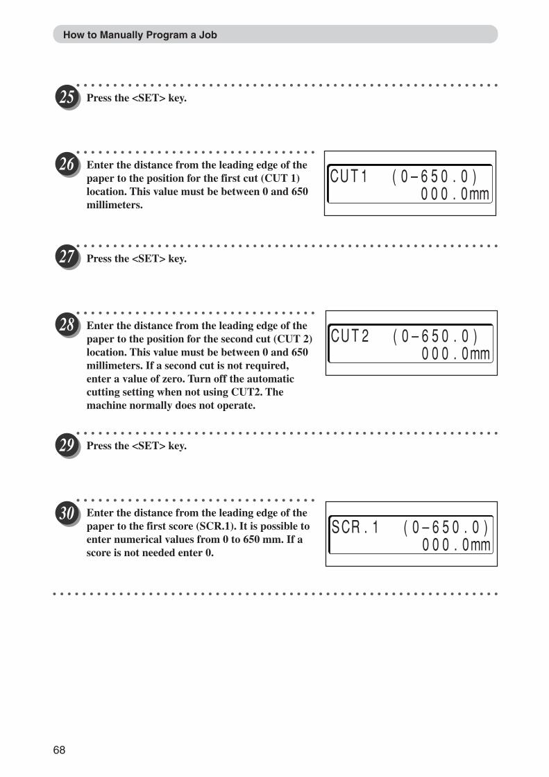
68
How to Manually Program a Job
○ ○ ○ ○ ○ ○ ○ ○ ○ ○ ○ ○ ○ ○ ○ ○ ○ ○ ○ ○ ○ ○ ○ ○ ○ ○ ○ ○ ○ ○ ○ ○ ○ ○ ○ ○ ○ ○ ○ ○ ○ ○ ○ ○ ○ ○ ○ ○ ○ ○ ○ ○ ○ ○ ○ ○ ○ ○
Press the <SET> key.
○ ○ ○ ○ ○ ○ ○ ○ ○ ○ ○ ○ ○ ○ ○ ○ ○ ○ ○ ○ ○ ○ ○ ○ ○ ○ ○ ○ ○ ○ ○ ○ ○
Enter the distance from the leading edge of thepaper to the position for the first cut (CUT 1)location. This value must be between 0 and 650millimeters.
○ ○ ○ ○ ○ ○ ○ ○ ○ ○ ○ ○ ○ ○ ○ ○ ○ ○ ○ ○ ○ ○ ○ ○ ○ ○ ○ ○ ○ ○ ○ ○ ○ ○ ○ ○ ○ ○ ○ ○ ○ ○ ○ ○ ○ ○ ○ ○ ○ ○ ○ ○ ○ ○ ○ ○ ○ ○
Press the <SET> key.
○ ○ ○ ○ ○ ○ ○ ○ ○ ○ ○ ○ ○ ○ ○ ○ ○ ○ ○ ○ ○ ○ ○ ○ ○ ○ ○ ○ ○ ○ ○ ○ ○
Enter the distance from the leading edge of thepaper to the position for the second cut (CUT 2)location. This value must be between 0 and 650millimeters. If a second cut is not required,enter a value of zero. Turn off the automaticcutting setting when not using CUT2. Themachine normally does not operate.
○ ○ ○ ○ ○ ○ ○ ○ ○ ○ ○ ○ ○ ○ ○ ○ ○ ○ ○ ○ ○ ○ ○ ○ ○ ○ ○ ○ ○ ○ ○ ○ ○ ○ ○ ○ ○ ○ ○ ○ ○ ○ ○ ○ ○ ○ ○ ○ ○ ○ ○ ○ ○ ○ ○ ○ ○ ○
Press the <SET> key.
○ ○ ○ ○ ○ ○ ○ ○ ○ ○ ○ ○ ○ ○ ○ ○ ○ ○ ○ ○ ○ ○ ○ ○ ○ ○ ○ ○ ○ ○ ○ ○ ○
Enter the distance from the leading edge of thepaper to the first score (SCR.1). It is possible toenter numerical values from 0 to 650 mm. If ascore is not needed enter 0.
○ ○ ○ ○ ○ ○ ○ ○ ○ ○ ○ ○ ○ ○ ○ ○ ○ ○ ○ ○ ○ ○ ○ ○ ○ ○ ○ ○ ○ ○ ○ ○ ○ ○ ○ ○ ○ ○ ○ ○ ○ ○ ○ ○ ○ ○ ○ ○ ○ ○ ○ ○ ○ ○ ○ ○ ○ ○ ○ ○ ○
CUT1 (0–650.0) 000.0mm
CUT2 (0–650.0) 000.0mm
SCR.1 (0–650.0) 000.0mm
Docu Cutter(HCEX) 5_53-69 03.12.8, 3:11 PM68
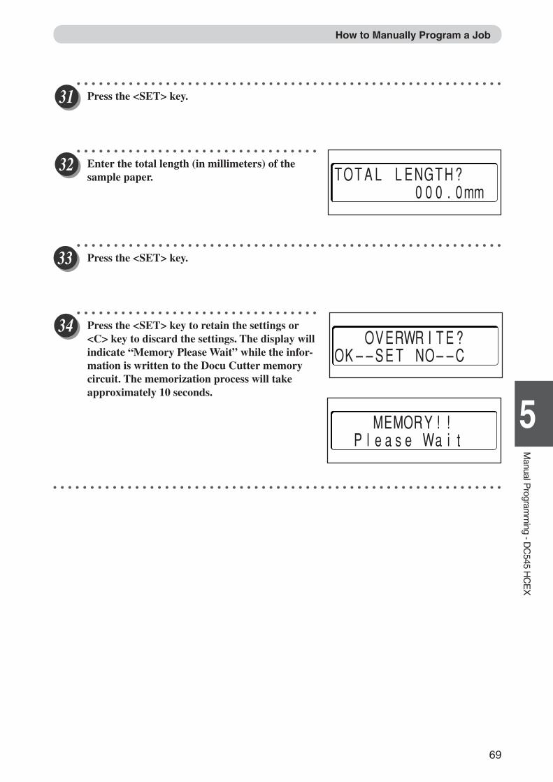
69
1
5
Manual P
rogramm
ing - DC
545 HC
EX
How to Manually Program a Job
○ ○ ○ ○ ○ ○ ○ ○ ○ ○ ○ ○ ○ ○ ○ ○ ○ ○ ○ ○ ○ ○ ○ ○ ○ ○ ○ ○ ○ ○ ○ ○ ○ ○ ○ ○ ○ ○ ○ ○ ○ ○ ○ ○ ○ ○ ○ ○ ○ ○ ○ ○ ○ ○ ○ ○ ○ ○
Press the <SET> key.
○ ○ ○ ○ ○ ○ ○ ○ ○ ○ ○ ○ ○ ○ ○ ○ ○ ○ ○ ○ ○ ○ ○ ○ ○ ○ ○ ○ ○ ○ ○ ○ ○
Enter the total length (in millimeters) of thesample paper.
○ ○ ○ ○ ○ ○ ○ ○ ○ ○ ○ ○ ○ ○ ○ ○ ○ ○ ○ ○ ○ ○ ○ ○ ○ ○ ○ ○ ○ ○ ○ ○ ○ ○ ○ ○ ○ ○ ○ ○ ○ ○ ○ ○ ○ ○ ○ ○ ○ ○ ○ ○ ○ ○ ○ ○ ○ ○
Press the <SET> key.
○ ○ ○ ○ ○ ○ ○ ○ ○ ○ ○ ○ ○ ○ ○ ○ ○ ○ ○ ○ ○ ○ ○ ○ ○ ○ ○ ○ ○ ○ ○ ○ ○
Press the <SET> key to retain the settings or<C> key to discard the settings. The display willindicate “Memory Please Wait” while the infor-mation is written to the Docu Cutter memorycircuit. The memorization process will takeapproximately 10 seconds.
○ ○ ○ ○ ○ ○ ○ ○ ○ ○ ○ ○ ○ ○ ○ ○ ○ ○ ○ ○ ○ ○ ○ ○ ○ ○ ○ ○ ○ ○ ○ ○ ○ ○ ○ ○ ○ ○ ○ ○ ○ ○ ○ ○ ○ ○ ○ ○ ○ ○ ○ ○ ○ ○ ○ ○ ○ ○ ○ ○ ○
TOTAL LENGTH? 000.0mm
OVERWRITE?OK––SET NO––C
MEMORY!! Please Wait
Docu Cutter(HCEX) 5_53-69 03.12.8, 3:12 PM69
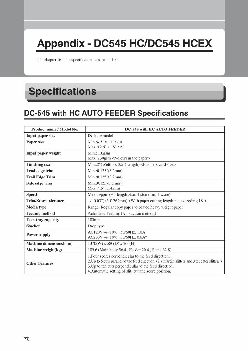
70
Appendix - DC545 HC/DC545 HCEXThis chapter lists the specifications and an index.
Specifications
Product name / Model No. DC-545 with HC AUTO FEEDER
Input paper size Desktop model
Paper size Min.:8.5" x 11" / A4Max.:12.6" x 18" / A3
Input paper weight Min.:110gsmMax.:230gsm <No curl in the paper>
Finishing size Min.:2"(Width) x 3.5"(Length) <Business card size>
Lead edge trim Min.:0.125"(3.2mm)
Trail Edge Trim Min.:0.125"(3.2mm)
Side edge trim Min.:0.125'(3.2mm)Max.:4.5"(114mm)
Speed Max : 9ppm (A4 lengthwise. 4-side trim. 1 score)
Trim/Score tolerance +/- 0.03"(+/- 0.762mm) <With paper cutting length not exceeding 18">
Media type Range: Regular copy paper to coated heavy weight paper
Feeding method Automatic Feeding (Air suction method)
Feed tray capacity 100mm
Stacker Drop type
Power supply AC120V +/- 10% , 50/60Hz, 1.0AAC230V +/- 10% , 50/60Hz, 0.6A*
Machine dimensions(mm) 1370(W) x 580(D) x 960(H)
Machine weight(kg) 109.6 (Main body 56.4 , Feeder 20.4 , Stand 32.8)
1.Four scores perpendicular to the feed direction.
Other Features 2.Up to 5 cuts parallel to the feed direction. (2 x margin slitters and 3 x center slitters.)3.Up to ten cuts perpendicular to the feed direction.4.Automatic setting of slit, cut and score position.
DC-545 with HC AUTO FEEDER Specifications
Docu Cutter(HCEX) 6_70-84 03.12.8, 3:12 PM70
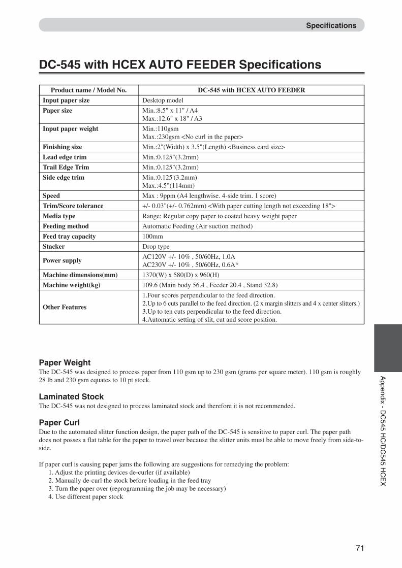
71
2
1
Appendix - D
C545 H
C/D
C545 H
CE
XSpecifications
Paper WeightThe DC-545 was designed to process paper from 110 gsm up to 230 gsm (grams per square meter). 110 gsm is roughly28 lb and 230 gsm equates to 10 pt stock.
Laminated StockThe DC-545 was not designed to process laminated stock and therefore it is not recommended.
Paper CurlDue to the automated slitter function design, the paper path of the DC-545 is sensitive to paper curl. The paper pathdoes not posses a flat table for the paper to travel over because the slitter units must be able to move freely from side-to-side.
If paper curl is causing paper jams the following are suggestions for remedying the problem:1. Adjust the printing devices de-curler (if available)2. Manually de-curl the stock before loading in the feed tray3. Turn the paper over (reprogramming the job may be necessary)4. Use different paper stock
Product name / Model No. DC-545 with HCEX AUTO FEEDER
Input paper size Desktop model
Paper size Min.:8.5" x 11" / A4Max.:12.6" x 18" / A3
Input paper weight Min.:110gsmMax.:230gsm <No curl in the paper>
Finishing size Min.:2"(Width) x 3.5"(Length) <Business card size>
Lead edge trim Min.:0.125"(3.2mm)
Trail Edge Trim Min.:0.125"(3.2mm)
Side edge trim Min.:0.125'(3.2mm)Max.:4.5"(114mm)
Speed Max : 9ppm (A4 lengthwise. 4-side trim. 1 score)
Trim/Score tolerance +/- 0.03"(+/- 0.762mm) <With paper cutting length not exceeding 18">
Media type Range: Regular copy paper to coated heavy weight paper
Feeding method Automatic Feeding (Air suction method)
Feed tray capacity 100mm
Stacker Drop type
Power supply AC120V +/- 10% , 50/60Hz, 1.0AAC230V +/- 10% , 50/60Hz, 0.6A*
Machine dimensions(mm) 1370(W) x 580(D) x 960(H)
Machine weight(kg) 109.6 (Main body 56.4 , Feeder 20.4 , Stand 32.8)
1.Four scores perpendicular to the feed direction.
Other Features 2.Up to 6 cuts parallel to the feed direction. (2 x margin slitters and 4 x center slitters.)3.Up to ten cuts perpendicular to the feed direction.4.Automatic setting of slit, cut and score position.
DC-545 with HCEX AUTO FEEDER Specifications
Docu Cutter(HCEX) 6_70-84 03.12.8, 3:12 PM71
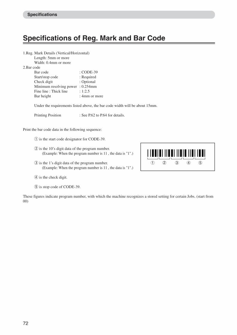
72
Specifications of Reg. Mark and Bar Code
1.Reg. Mark Details (Vertical/Horizontal)Length: 5mm or moreWidth: 0.4mm or more
2.Bar codeBar code : CODE-39Start/stop code : RequiredCheck digit : OptionalMinimum resolving power : 0.254mmFine line : Thick line : 1:2.5Bar height : 4mm or more
Under the requirements listed above, the bar code width will be about 15mm.
Printing Position : See P.62 to P.64 for details.
Print the bar code data in the following sequence:
q is the start code designator for CODE-39.
w is the 10’s digit data of the program number.(Example: When the program number is 11 , the data is "1".)
e is the 1’s digit data of the program number.(Example: When the program number is 11 , the data is "1".)
r is the check digit.
t is stop code of CODE-39.
These figures indicate program number, with which the machine recognizes a stored setting for certain Jobs. (start from00)
1 2 3 4 5
Specifications
Docu Cutter(HCEX) 6_70-84 03.12.8, 3:12 PM72
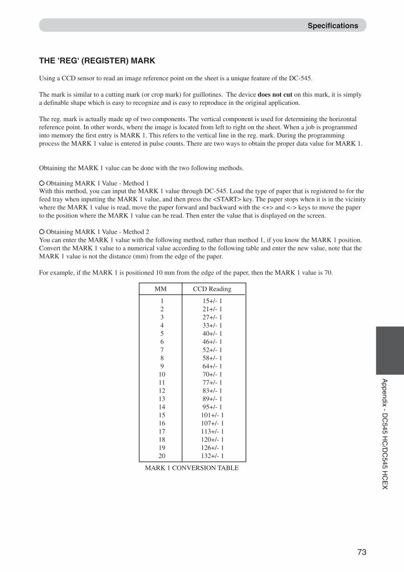
73
2
1
Appendix - D
C545 H
C/D
C545 H
CE
XSpecifications
THE 'REG' (REGISTER) MARK
Using a CCD sensor to read an image reference point on the sheet is a unique feature of the DC-545.
The mark is similar to a cutting mark (or crop mark) for guillotines. The device does not cut on this mark, it is simplya definable shape which is easy to recognize and is easy to reproduce in the original application.
The reg. mark is actually made up of two components. The vertical component is used for determining the horizontalreference point. In other words, where the image is located from left to right on the sheet. When a job is programmedinto memory the first entry is MARK 1. This refers to the vertical line in the reg. mark. During the programmingprocess the MARK 1 value is entered in pulse counts. There are two ways to obtain the proper data value for MARK 1.
Obtaining the MARK 1 value can be done with the two following methods.
Obtaining MARK 1 Value - Method 1With this method, you can input the MARK 1 value through DC-545. Load the type of paper that is registered to for thefeed tray when inputting the MARK 1 value, and then press the <START> key. The paper stops when it is in the vicinitywhere the MARK 1 value is read, move the paper forward and backward with the <+> and <-> keys to move the paperto the position where the MARK 1 value can be read. Then enter the value that is displayed on the screen.
Obtaining MARK 1 Value - Method 2You can enter the MARK 1 value with the following method, rather than method 1, if you know the MARK 1 position.Convert the MARK 1 value to a numerical value according to the following table and enter the new value, note that theMARK 1 value is not the distance (mm) from the edge of the paper.
For example, if the MARK 1 is positioned 10 mm from the edge of the paper, then the MARK 1 value is 70.
MM CCD Reading
1 15+/- 12 21+/- 13 27+/- 14 33+/- 15 40+/- 16 46+/- 17 52+/- 18 58+/- 19 64+/- 1
10 70+/- 111 77+/- 112 83+/- 113 89+/- 114 95+/- 115 101+/- 116 107+/- 117 113+/- 118 120+/- 119 126+/- 120 132+/- 1
MARK 1 CONVERSION TABLE
Docu Cutter(HCEX) 6_70-84 03.12.8, 3:12 PM73
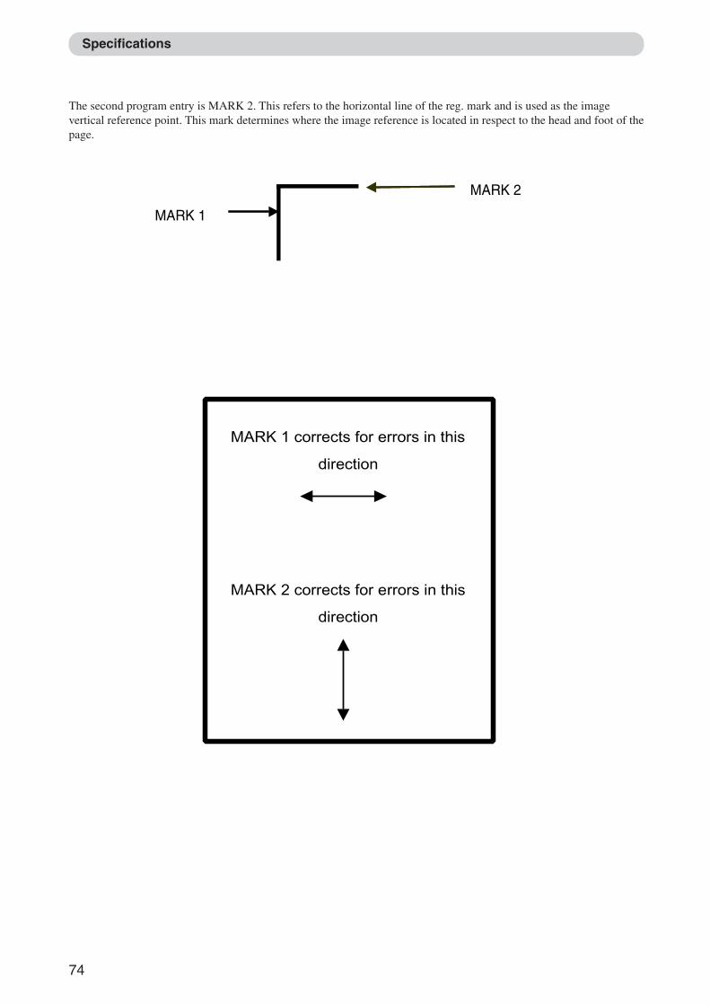
74
The second program entry is MARK 2. This refers to the horizontal line of the reg. mark and is used as the imagevertical reference point. This mark determines where the image reference is located in respect to the head and foot of thepage.
Specifications
MARK 1
MARK 2
MARK 1 corrects for errors in this
direction
MARK 2 corrects for errors in this
direction
Docu Cutter(HCEX) 6_70-84 03.12.8, 3:12 PM74
75
2
1
Appendix - D
C545 H
C/D
C545 H
CE
XSpecifications
HOW TO MAKE A BAR CODE FOR USE WITH THE DC-545
The easiest way to create the code is with a TrueType Font. Fonts are readily available from many companies on theinternet. Here are two companies which have fonts suitable for use with the DC-545 (there are many companies offeringfonts).
www.azalea.com/code39Azalea offers a free sample of code 39 and a variety of customizable options that allow printing of bar codesfrom Microsoft Windows™ or Macintosh™ platforms.
http://www.datascan.co.ukSamples - standard font Price £149 for a single user; £298 for 2-5
Basic Font Installation Instructions
The following briefly describes what is required to install a font on a Windows or Macintosh system. The font providerwill supply more detailed information, these guidelines are only intended to illustrate the basics and scope of theinstallation process.
On a Windows PC the font is installed through the Control Panel's "Fonts" folder.
On a Macintosh system select the font suitcases (for TrueType 1 fonts also select the printer outline files) and drag thefonts onto the closed System Folder icon. For OS X drag the fonts onto the Fonts folder in the Library folder.
How to use a TrueType font
Once installed, the font will appear in the word processing or desktop publishing application in the font selection area.Please note in MS Word, typing text surrounded by the characters * and *, automatically turns on auto format to boldtext. Since this is not the intended, or useful, turn off the auto formatting by following the steps below or use the 'undolast action' after typing.
Docu Cutter(HCEX) 6_70-84 03.12.8, 3:12 PM75
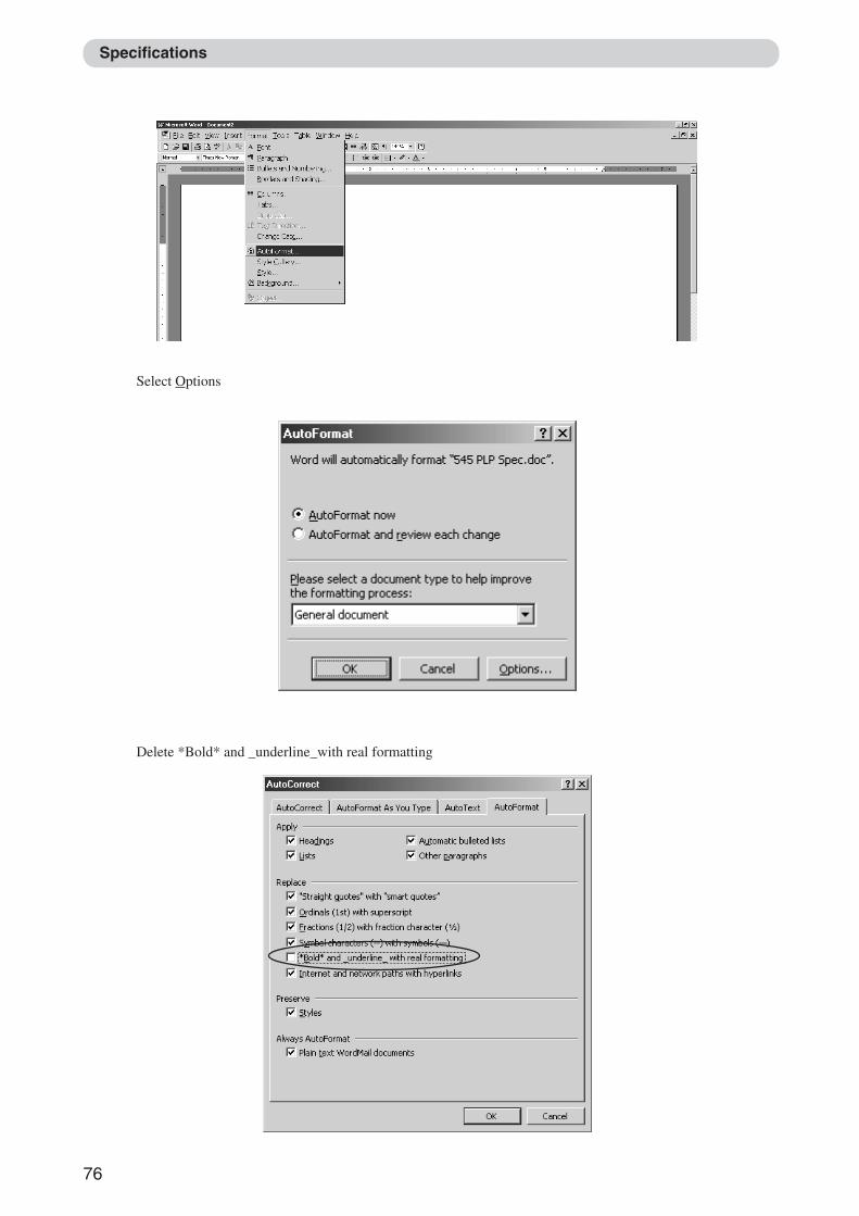
76
Specifications
Select Options
Delete *Bold* and _underline_with real formatting
Docu Cutter(HCEX) 6_70-84 03.12.8, 3:12 PM76
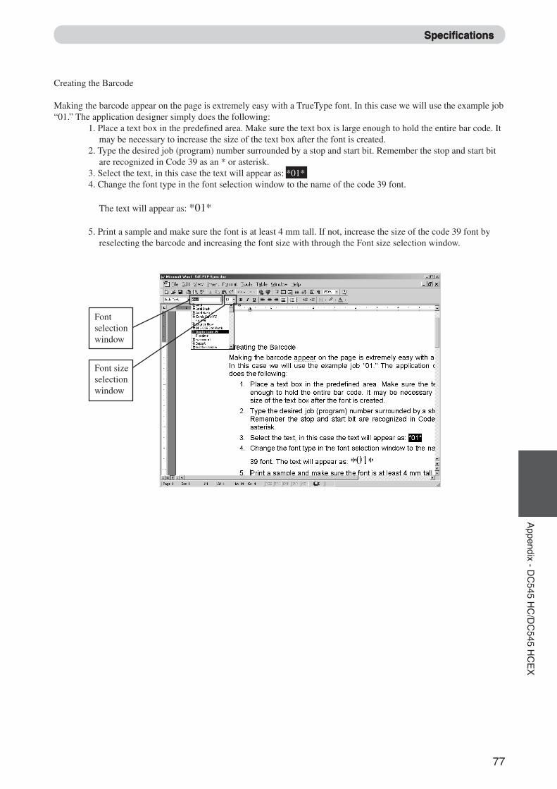
77
2
1
Appendix - D
C545 H
C/D
C545 H
CE
XSpecifications
Duplo Code 39
Fontselectionwindow
Font sizeselectionwindow
Specifications
Creating the Barcode
Making the barcode appear on the page is extremely easy with a TrueType font. In this case we will use the example job“01.” The application designer simply does the following:
1. Place a text box in the predefined area. Make sure the text box is large enough to hold the entire bar code. Itmay be necessary to increase the size of the text box after the font is created.
2. Type the desired job (program) number surrounded by a stop and start bit. Remember the stop and start bitare recognized in Code 39 as an * or asterisk.
3. Select the text, in this case the text will appear as: *01*4. Change the font type in the font selection window to the name of the code 39 font.
The text will appear as: *01*
5. Print a sample and make sure the font is at least 4 mm tall. If not, increase the size of the code 39 font byreselecting the barcode and increasing the font size with through the Font size selection window.
Docu Cutter(HCEX) 6_70-84 03.12.8, 3:12 PM77
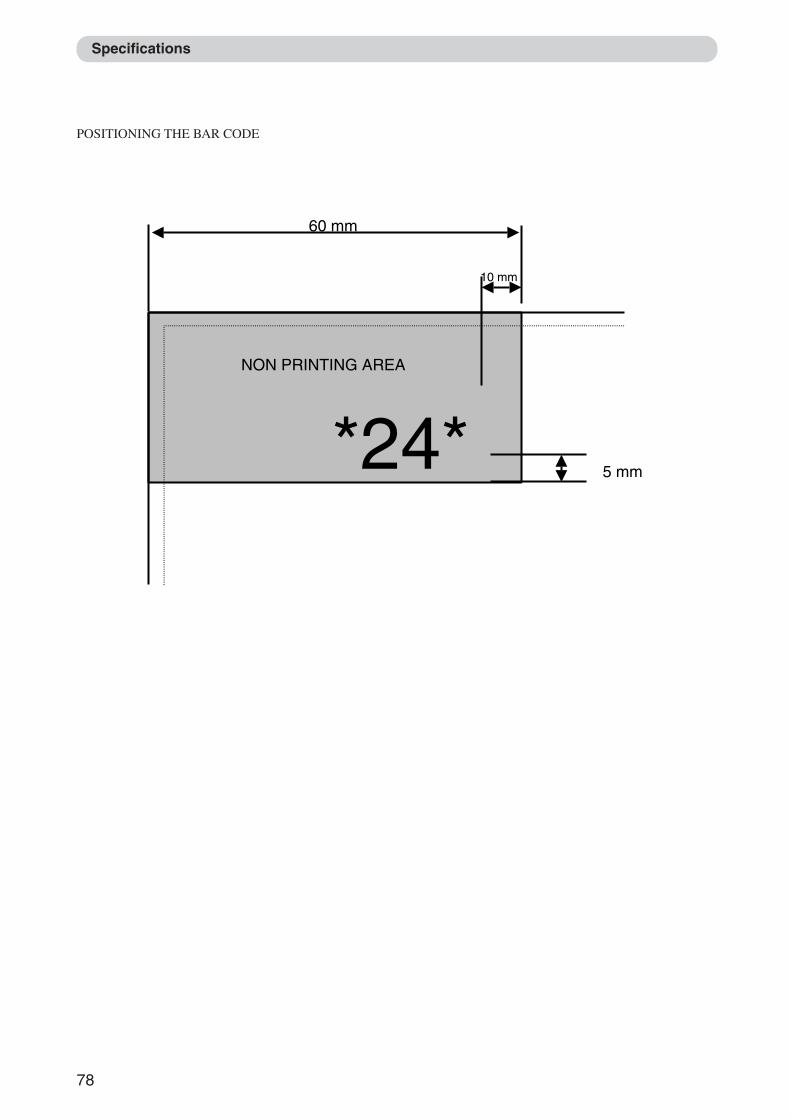
78
Specifications
POSITIONING THE BAR CODE
NON PRINTING AREA
5 mm
10 mm
*24*
60 mm
Docu Cutter(HCEX) 6_70-84 03.12.8, 3:12 PM78
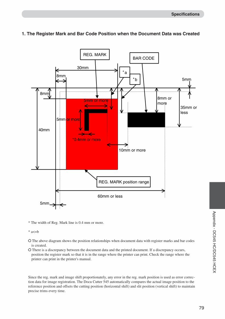
79
2
1
Appendix - D
C545 H
C/D
C545 H
CE
X
10mm or more
35mm or less
60mm or less
30mm
8mm
8mm
5mm
5mm
BAR CODEREG. MARK
*a
*b
5mm or more
40mm
REG. MARK position range
5mm or more 8mm or more
*0.4mm or more
* The width of Reg. Mark line is 0.4 mm or more.
* a<=b
The above diagram shows the position relationships when document data with register marks and bar codesis created. There is a discrepancy between the document data and the printed document. If a discrepancy occurs,position the register mark so that it is in the range where the printer can print. Check the range where theprinter can print in the printer's manual.
Since the reg. mark and image shift proportionately, any error in the reg. mark position is used as error correc-tion data for image registration. The Docu Cutter 545 automatically compares the actual image position to thereference position and offsets the cutting position (horizontal shift) and slit position (vertical shift) to maintainprecise trims every time.
Specifications
1. The Register Mark and Bar Code Position when the Document Data was Created
Docu Cutter(HCEX) 6_70-84 03.12.8, 3:12 PM79
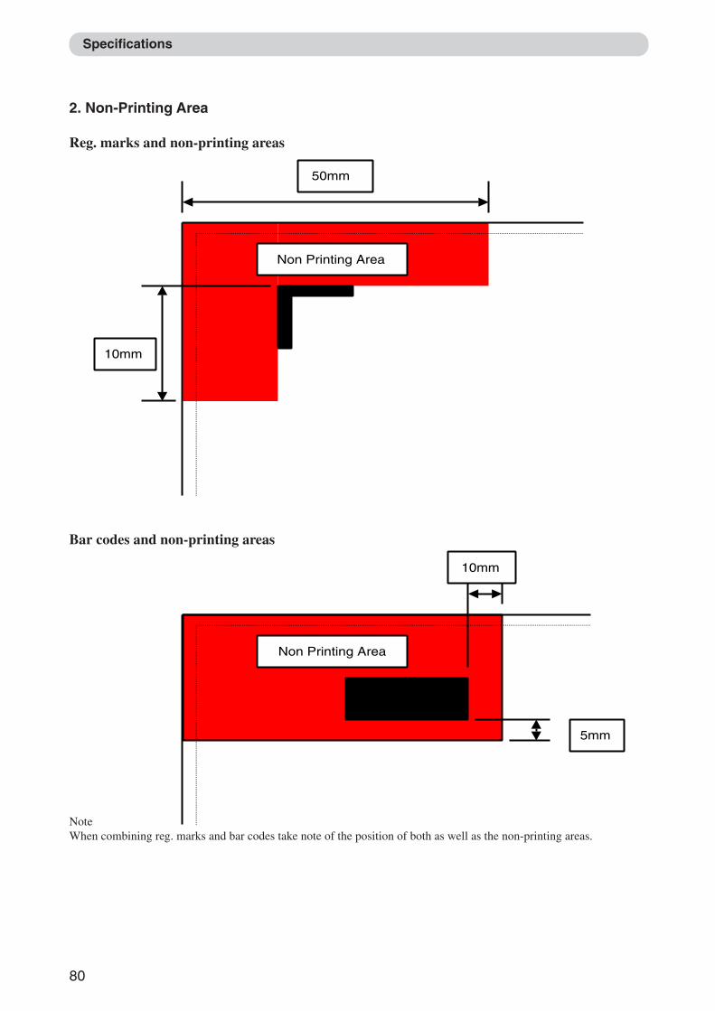
80
Non Printing Area
10mm
50mm
Non Printing Area
5mm
10mm
Specifications
2. Non-Printing Area
Reg. marks and non-printing areas
Bar codes and non-printing areas
NoteWhen combining reg. marks and bar codes take note of the position of both as well as the non-printing areas.
Docu Cutter(HCEX) 6_70-84 03.12.8, 3:12 PM80
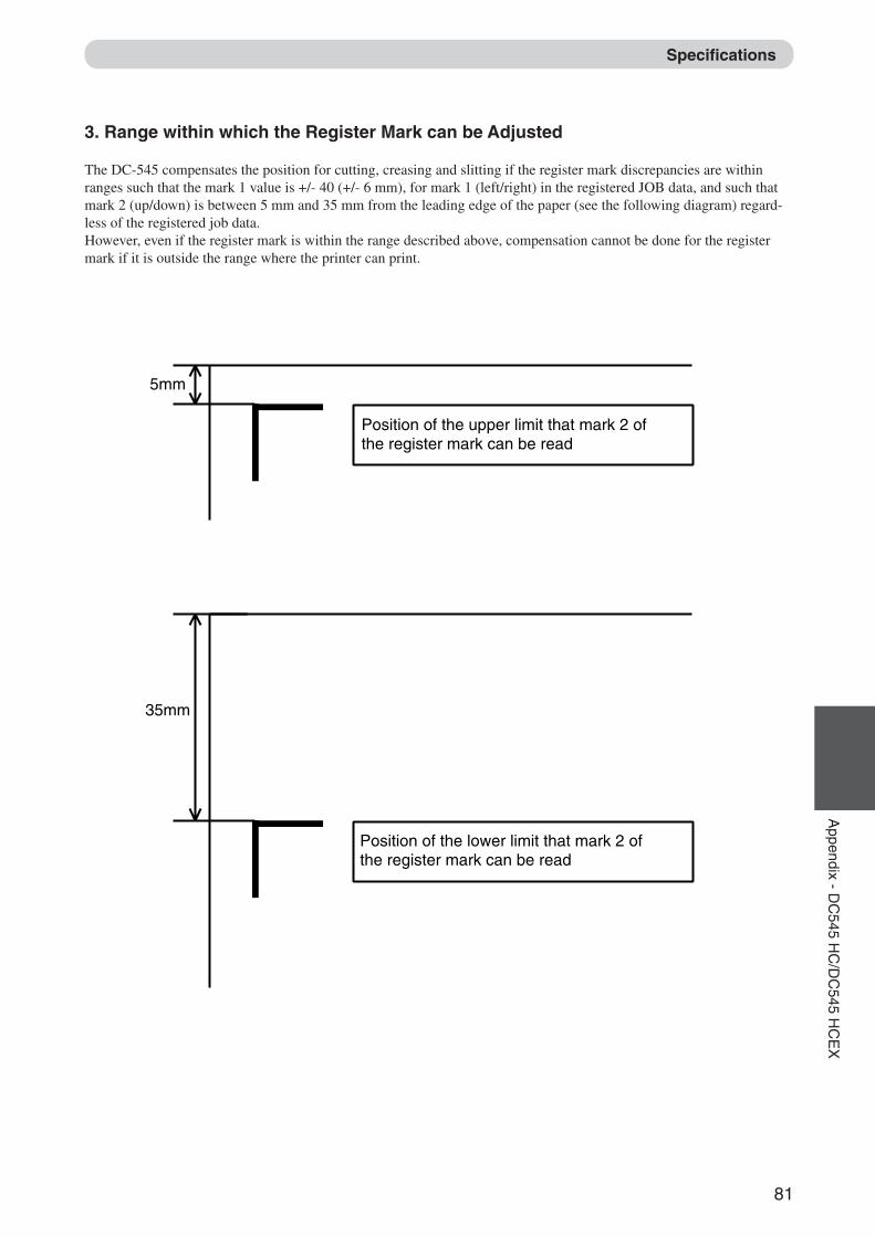
81
2
1
Appendix - D
C545 H
C/D
C545 H
CE
X
3. Range within which the Register Mark can be Adjusted
The DC-545 compensates the position for cutting, creasing and slitting if the register mark discrepancies are withinranges such that the mark 1 value is +/- 40 (+/- 6 mm), for mark 1 (left/right) in the registered JOB data, and such thatmark 2 (up/down) is between 5 mm and 35 mm from the leading edge of the paper (see the following diagram) regard-less of the registered job data.However, even if the register mark is within the range described above, compensation cannot be done for the registermark if it is outside the range where the printer can print.
Specifications
5mm
35mm
Position of the upper limit that mark 2 of the register mark can be read
Position of the lower limit that mark 2 of the register mark can be read
Docu Cutter(HCEX) 6_70-84 03.12.8, 3:12 PM81
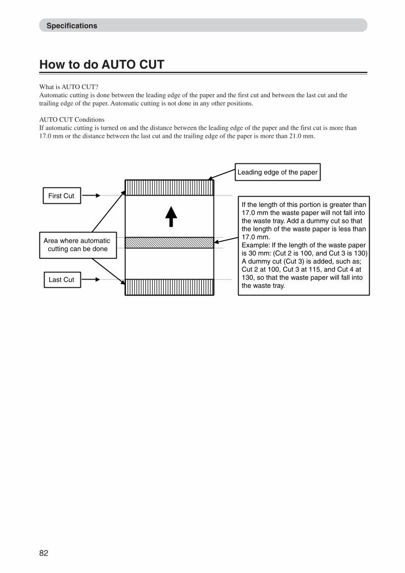
82
If the length of this portion is greater than 17.0 mm the waste paper will not fall into the waste tray. Add a dummy cut so that the length of the waste paper is less than 17.0 mm. Example: If the length of the waste paper is 30 mm: (Cut 2 is 100, and Cut 3 is 130)A dummy cut (Cut 3) is added, such as; Cut 2 at 100, Cut 3 at 115, and Cut 4 at 130, so that the waste paper will fall into the waste tray.
Area where automatic cutting can be done
Leading edge of the paper
First Cut
Last Cut
Specifications
How to do AUTO CUT
What is AUTO CUT?Automatic cutting is done between the leading edge of the paper and the first cut and between the last cut and thetrailing edge of the paper. Automatic cutting is not done in any other positions.
AUTO CUT ConditionsIf automatic cutting is turned on and the distance between the leading edge of the paper and the first cut is more than17.0 mm or the distance between the last cut and the trailing edge of the paper is more than 21.0 mm.
Docu Cutter(HCEX) 6_70-84 03.12.8, 3:12 PM82
About the Waste Tray ................................................. 29Appearance ................................................................. 21Automatic Cutting Using Bar Codes andRegister Marks ............................................................ 26
Bar code ...................................................................... 26
<CLEAR> key ............................................................ 23Conventions Used in This Manual .............................. 17Confirming the Packaged Materials ........................... 18Control Panel ........................................................ 21, 23COVER lamp .............................................................. 23Customer Programmed Jobs ....................................... 60Cutting is Not Possible ............................................... 31
Definition of Programming Terms.............................. 54
Error Messages ........................................................... 32
Factory Preset Jobs ..................................................... 45Feed guides ........................................................... 13, 26Feed lamp ............................................................. 13, 26Feed tray ............................................................... 13, 26 <F> key ...................................................................... 23Front cover ...................................................... 21, 23, 25
How to Manually Program a Job ................................ 64How to Set up the System........................................... 19
Instruction Manual ...................................................... 18
JAM lamp ............................................................. 23, 39
Key pad ....................................................................... 23
LCD panel ................................................ 23, 24, 25, 27
<MODE> key ............................................................. 23Maintenance ............................................................... 10
Part Names and Their Functions ................................ 21PAPER lamp ............................................................... 23Paper tray .............................................................. 18, 19Positioning the Machine ............................................... 9Power Does Not Turn ON .......................................... 30POWER lamp ............................................................. 23Power switch ......................................................... 22, 25Preset number ................................................. 23, 24, 25Prior to Programming a Job ........................................ 53
Rear cover ....................................................... 21, 22, 23Reg. Mark ................... 24, 26, 27, 35, 53, 54, 57, 64, 72
<SET> key ............................................................ 23, 64Safety Precautions ........................................................ 5Screw Driver ............................................................... 18Specifications .............................................................. 70Specifications of Reg. Mark and Bar code ................... 72Specifications of the Machine .................................... 70<START> key ............................................................. 23START lamp ............................................................... 23Status .......................................................................... 24<STOP> key ................................................... 23, 41, 47
Troubleshooting Flow Chart ....................................... 30Turning OFF the Power .............................................. 25Turning ON the Power ................................................ 25Turning Power ON/OFF ............................................. 25Tweezers ............................................................... 18, 39
Warning Sticker ............................................................ 8Waste tray ....................................................... 21, 27, 29Waste tray cover ................................................... 21, 29When a Paper Jam Has Occurred ............................... 39When “CENTER JAM” is Displayed ......................... 43When “CREASE LOCK” is Displayed ...................... 51When “CUTTER LOCK” is Displayed ...................... 49When “FEED JAM” is Displayed .............................. 41When “REJECT PAPER” is Displayed ...................... 39When “SLITTER JAM” is Displayed ........................ 47
<+> key ....................................................................... 23<-> key ........................................................................ 23
A
C
F
H
I
J
K
L
M
P
R
S
T
W
Other
B
Index
D
E
Docu Cutter(HCEX) 6_70-84 03.12.8, 3:12 PM83

MEMO
Docu Cutter(HCEX) 6_70-84 03.12.8, 3:12 PM84

MEMO
Docu Cutter(HCEX) 6_70-84 03.12.8, 3:12 PM85

MEMO
Docu Cutter(HCEX) 6_70-84 03.12.8, 3:12 PM86

N4-Y1013