document number 20093034 (formerly ami-c 3034)...
TRANSCRIPT

Document number 20093034 (Formerly AMI-C 3034)
AMI-C Power Management Test V1.00
April 6, 2009 Sponsored by:
1394 Trade Association
Accepted for publication by
This draft specification has been accepted by the 1394 Trade Association Board of Directors
Abstract
This specification is based on AMI-C 3034 Power Management Test Document V1.00. This document describes the test approaches, test set up and test cases, which have been used during the AMI-C –EPOC for the successful dem-onstration of power management capability of EPOC.
Keywords
IEEE 1394, Serial Bus, AMI-C, Automotive, Power Management Test

AMI-C 3034
AMI-C 3034 Power Management Test Document. V1.00
2005-08-24
1394 Trade Association Specification

1394 Trade Association Specifications are devel-oped within Working Groups of the 1394 Trade Association, a non-profit industry asso-ciation devoted to the
promotion of and growth of the market for IEEE 1394-compliant products. Participants in Working Groups serve voluntarily and without compensation from the Trade Associa-tion. Most participants represent member organizations of the 1394 Trade Association. The specifications developed within the working groups represent a consensus of the ex-pertise represented by the participants. Use of a 1394 Trade Association Specification is wholly voluntary. The existence of a 1394 Trade Association Specification is not meant to imply that there are not other ways to produce, test, measure, purchase, market or provide other goods and services related to the scope of the 1394 Trade Association Specification. Furthermore, the viewpoint ex-pressed at the time a specification is accepted and issued is subject to change brought about through developments in the state of the art and comments received from users of the specification. Users are cautioned to check to determine that they have the latest revi-sion of any 1394 Trade Association Specification. Comments for revision of 1394 Trade Association Specifications are welcome from any interested party, regardless of membership affiliation with the 1394 Trade Association. Suggestions for changes in documents should be in the form of a proposed change of text, together with appropriate supporting comments. Interpretations: Occasionally, questions may arise about the meaning of specifications in relationship to specific applications. When the need for interpretations is brought to the attention of the 1394 Trade Association, the Association will initiate action to prepare appropriate responses. Comments on specifications and requests for interpretations should be addressed to:
Editor, 1394 Trade Association 1560 East Southlake Blvd, Suite 220 Southlake, TX 76092 USA 1394 Trade Association Specifications are adopted by the 1394 Trade Association without regard to patents which may exist on articles, ma-terials or processes or to other proprietary intellectual property which may exist within a specification. Adoption of a specification by the 1394 Trade Association does not assume any liability to any patent owner or any obligation whatsoever to those parties who rely on the specification documents. Readers of this document are advised to make an independent determination regarding the existence of intellec-tual property rights, which may be infringed by conformance to this specification.
Published by
1394 Trade Association 1560 East Southlake Blvd, Suite 220 Southlake, TX 76092 USA
Copyright © 2009 by 1394 Trade Association All rights reserved.
Printed in the United States of America


1394 TA 20093034
3 Copyright © 2009, 1394 Trade Association. All rights reserved.
Trademarks cited in this document Any trademarks, registered trademarks, or service marks used in this document are the property of their respective owners and are hereby recognized. Name Phrase

1394 TA 20093034
4 Copyright © 2009, 1394 Trade Association. All rights reserved.
Revision log
Document no.
Version no. 1.00
Version date 2005-0x-xx
Document title AMI-C Revision date Affected sections 2005-0x-xx Version 1.00 released for publication. This version is the basis for all
future revisions.

1394 TA 20093034
5 Copyright © 2009, 1394 Trade Association. All rights reserved.
Contents Foreword ............................................................................................................ 6 Introduction......................................................................................................... 7 Scope 7 References ......................................................................................................... 7 1.1 Normative references............................................................................... 7 1.2 Informative references ............................................................................. 7 Required Resources........................................................................................... 7 Test set up overview.............................................................................................. 7 PM EPoC Installation Procedure ...................................................................... 10 PM EPoC Operating Procedure........................................................................ 10 Use cases......................................................................................................... 12 Test Case Grouping ......................................................................................... 12 Observation Mechanisms ................................................................................. 13 Test Case Definition ......................................................................................... 13 7.1 TC_PM_ST _01..................................................................................... 13 7.2 TC_PM_ST _02....................................................................................... 15 7.3 TC_PM_ST _03......................................................................................... 16 7.4 TC_PM_ST _04........................................................................................ 17 7.5 TC_PM_ST _05......................................................................................... 18 7.6 TC_PM_ST _06........................................................................................ 19 7.7 TC_PM_ST _07........................................................................................ 20 7.8 TC_PM_ST _08........................................................................................ 21 7.9 TC_PM_ST _09......................................................................................... 22 8 Test Results................................................................................................... 24 9. Tools /Other Software Used ......................................................................... 24 Annex A Requirement and recommendation language .................................... 26 A.1 Requirements ........................................................................................ 26 A.2 Recommendations ................................................................................. 26 Annex B Request for change form ................................................................... 27
Figures Figure 1 – AMIC-EPOC system.........................Error! Bookmark not defined. Figure 2 -- AMIC-EPOC system test set up Tables Table 1 – Hardware Requirements................................................................. 25

1394 TA 20093034
6 Copyright © 2009, 1394 Trade Association. All rights reserved.
Foreword

1394 TA 20093034
7 Copyright © 2009, 1394 Trade Association. All rights reserved.
Introduction This document describes the test approaches, test set up and test cases, which have been used during the AMI-C –EPOC for the successful demonstration of power management capability of EPOC. This document mainly focuses how to build a test set up, install the software components and running the test cases given in this document
Scope For the successful functioning of EPOC, the integration as well as the interop-erability of the software and hardware components developed by various con-tributing organizations must be tested and validated. This document brings out a test plan for developing the test cases, which can be used during these test-ing and validation activity. These test cases will consist of System test cases
References 1.1 Normative references
1. Power Management EPoC SW Architecture_v0.9 2. AMI-C 1394 automotive test design specification-power management
V0.90 3. AMI-C Power Management EPoC User Manual
1.2 Informative references PM EPoC_IF-BOX_Cnctn_r01 EPoC (Phase 3) Integration Plan AMI-C 1394 Power Management EPoC P-Mode I/F-BOX Specification
2 Required Resources Refer the table 1 which describes the hardware Requirements.
3 Test set up overview It is assumed that all the EPoC software components are unit tested before they are tak-en up for integration The figure 1 shows AMIC-EPoC system, which basically consists of a Power Master PC and a Power Slave PC complying with the specifications of Host and Device units. To demonstrate Power cycles, the video output of an IIDC Cam-

1394 TA 20093034
8 Copyright © 2009, 1394 Trade Association. All rights reserved.
era displayed on the Power Slave PC will be started or suspended based on Power status of the 1394 network. The EPoC uses an external Power Status Line to provide wake up/shutdown signals/events to the network. This Power Status Line is called Power Mode (PM) Line. A change in the signal level of the PM-Line causes the wake up/shutdown of the repeaters, which in turn results in wake up/shutdown of the entire network. This change in signal level of PM-Line is detected by P-Mode monitoring appli-cations (P-Mode Slave) running in each node and interfaced with the PM Line using “I/F” box cable .The P-Mode I/F Box receives “Sleep” or “Wake Up” Con-trol data over a serial line from the Host Unit and controls the power status of all repeaters. The Key Position application, which simulates the status of the Igni-tion key in a real vehicular situation, initiates transfer of this Control data to change the Power Status of the network through the P-Mode Master Applica-tion. AMIC-EPOC system
Figure -1 AMIC-EPOC system
Power Master Key Position
Application
Power Slave Application
CCM
Camera Ap-plication
Power Slave Application
CCMIIDC Camera
I/F Box
I/F Box
Repeater Repeater Repeater
DEVICE PC
RM
HOST PC
SPM

1394 TA 20093034
9 Copyright © 2009, 1394 Trade Association. All rights reserved.
Figure -2 AMIC-EPOC system test set up A camera application GUI is used for controlling the properties of the IIDC camera. This IIDC camera is connected network using a P-Mode repeater In the figure 2, the components numbered 1 and 2 indicate Component 1 = P-Mode signal converter Component 2 = P-Mode repeater Component 3 = IIDC camera The component; P-Mode repeater 2.a is connected to component 3, which is an IIDC camera. This camera is controlled by the camera application residing at the device unit. This camera is connected to the repeater by using a 1394a Metal cable. The repeaters at the host unit, device unit and the repeater, which connects the IIDC camera, are pow-ered by using the PM line cable. The P-Mode signal converters are connected to Host and Device units PCs by RS232C cables. The test set up building is as follows 1. Connect P-Mode signal converter and P-Mode repeater using the PM line cable. 2. Connect IEEE 1394 cables at the IEEE 1394 ports. 3. Power up the device PC first and then host PC. 4. Switch on the P-Mode repeaters and P-Mode signal converters

1394 TA 20093034
10 Copyright © 2009, 1394 Trade Association. All rights reserved.
5. Connect the IIDC Camera as shown in the set up 6. 1394 Bus Analyzer is to be connected to the POF or to the metal cable whenever the transaction packets over them, needs to be analyzed
3.1 PM EPoC Installation Procedure
The following are the name of binary files for PM EPOC components: 1. CCMFm (Component Control Manager Functional Module) 2. _Controls (Local Application: Camera Control GUI)
Please follow the steps as mentioned below for the installation of PM EPOC components:
1. Please copy all the binary files to a common location in the file system. 2. Make sure that there are no files or pipes exist in the above location,
which can clash with the pipe names as per the AMIC EPOC Software Architecture document
3. If there is any pipes created by previous run of PM EPOC component exist in this location, please delete them all.
4. Remove the preinstalled OHCI and 1394 driver (Comes with the Red Hat Linux system)
rmmod ohci1394 rmmod ieee1394
5. Remove Wipro Driver if already installed for previous run of PM EPOC Components.
rmmod WiproDrv1394 6. Install Wipro Driver afresh to ensure that initializations are proper.
insmod WiproDrv1394.o
3.2 PM EPoC Operating Procedure Please follow the steps as mentioned below for running the PM EPOC components:
1. On the Host Unit, a. Open a new terminal and start Component Control Manager as
follows: ./CCMFm Host Configure_LPM.cfg
Where Configure_LPM.cfg is configuration file name for LPM. This file may have one of the following three values:

1394 TA 20093034
11 Copyright © 2009, 1394 Trade Association. All rights reserved.
0 – Shutdown Accept (Shutdown Normal Scenario) 1 – Shutdown Reject (Shutdown Forced Scenario) 2 – No Response (Shutdown Forced Scenario)
b. In a separate terminal, start System Power Master as follows: . /SPMFm
c. In a separate terminal, start PMode Master as follows: . /PmodeMasterFm
d. In a separate terminal, start PMode Slave as follows: . /PmodeSlaveFm
e. In a separate terminal, start Key Position Application as follows: . /KeyApp
2. On the Device Unit, a. Open a new terminal and start Component Control Manager as
follows: ./CCMFm Device Configure_LPM.cfg
Where Configure_LPM.cfg is configuration file name for LPM. This file may have one of the following three values: 0 – Shutdown Accept (Shutdown Normal Scenario) 1 – Shutdown Reject (Shutdown Forced Scenario) 2 – No Response (Shutdown Forced Scenario)
b. In a separate terminal, start Camera Application as follows: . /CameraAppFm
c. In a separate terminal, start PMode Slave as follows: . /PmodeSlaveFm
3. On the Host Unit, a. Make sure that all components have been started before running
Resource Manager. Then in a separate terminal, start Resource Manager as follows:
. /RMFm
4. After Resource Manager is started, please make sure that System Start up Sequence is executed as described in the AMI-C PM EPOC Software Architecture document (Refer Power Management EPoC SW Architec-ture_v0.9).
4. On System Startup, the system is in Wake-up State. 5. From Key Position Application, send “Key Position OFF” command to
start Shutdown sequence. 6. When the system is in Shutdown State, send “Key Position ON” from the
Key Position Application to start Wakeup Sequence. The configuration file for LPM can be changed to simulate various Shutdown scenarios as described above. The configuration file in the host and device unit can be modified anytime, and does not need restarting any PM EPOC compo-nent.

1394 TA 20093034
12 Copyright © 2009, 1394 Trade Association. All rights reserved.
4 Use cases The following are the use cases of the Power Management EPOC which were subjected to test • System Start up Sequences and registrations of Functional modules • Power Management capability of EPoC _ Wake up through Key Position Application _ Shutdown through Key Position Application _ Shutdown procedure using “shutdown by force” method • Initialization Sequence after Bus Reset across the network • Operation of the legacy devices
5 Test Case Grouping Test cases are mainly classified into four groups, which are Group A- Bus reset and system start up sequence. The Group A consists of test cases, which focus on the initial start up sequence and Post Bus Reset actions which Include registration of local functional modules with the Component Control Manager, Instance number allocation for functional modules that need dynamic instance numbers and using Address Resolution Protocol to determine actual Physical address of nodes after bus reset. 1. Verify the EPoC System Start up Sequence 2. Verify the Bus Reset functionality
Group B- System wake-up and shutdown sequence This group of test cases tests and validates power management capability of the EPoC System. 1. Verification of System Wake up functionality 2. Verification of both Cooperative and Forced System Shutdown / sleep functionality Group C- Suspend and resume of Local applications. This group of test cases is used for suspending and resuming the local applications pre-sent in the network. In this EPoC, an IIDC Camera has been used as an example of leg-

1394 TA 20093034
13 Copyright © 2009, 1394 Trade Association. All rights reserved.
acy device for demonstrating the power management capabilities. As explained earlier, the local power Manager controls the camera application power state. 1. Verify Resumption of Local applications. 2. Verify shut down of the Local applications
Group D- Legacy ports enabling and disabling These test cases validate EPoC power management capability for handling legacy de-vices by enabling or disabling the ports connected to legacy devices when wake up or shutdown command received is issued by SPM 1. Verify Enabling of the ports connected legacy devices. 2. Verify Disabling of the ports connected legacy devices.
6 Observation Mechanisms The group B and C test result observation was achieved by manual inspection The group A and D test case results were observed using the log facility. Also the IEEE1394 packet analyzer was used extensively for checking, and verifying the cor-rectness of the packets, which includes size of the packet, value of the control parame-ters etc. The procedure followed for this is described below 1. The input packet, control parameters (specific to each packet), which were generated at the host PC, was observed using the log message generated at the host side PC by the respective FMs. 2. In-cable message transactions, packet size; control parameters (specific to each command) etc were observed using the IEEE1394 packet analyzer. 3. The packets reached at the device PC were again cross checked for data integrity and for making sure that no data or packet were occurred during the transmission
Test Case Definition
7.1 TC_PM_ST _01 Test Case Spec. ID TC_PM_ST _01
1394 TA 20093034
14 Copyright © 2009, 1394 Trade Association. All rights reserved.
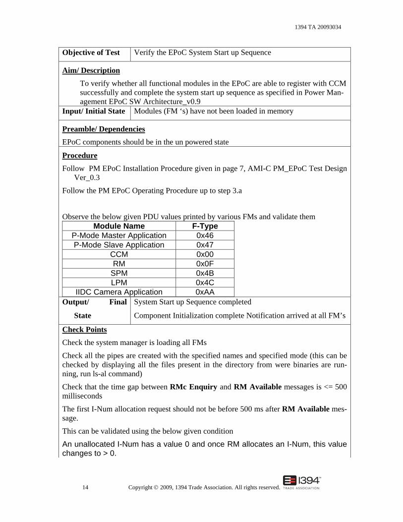
Objective of Test Verify the EPoC System Start up Sequence
Aim/ Description To verify whether all functional modules in the EPoC are able to register with CCM successfully and complete the system start up sequence as specified in Power Man-agement EPoC SW Architecture_v0.9
Input/ Initial State Modules (FM ‘s) have not been loaded in memory
Preamble/ Dependencies EPoC components should be in the un powered state
Procedure Follow PM EPoC Installation Procedure given in page 7, AMI-C PM_EPoC Test Design
Ver_0.3
Follow the PM EPoC Operating Procedure up to step 3.a
Observe the below given PDU values printed by various FMs and validate them Module Name F-Type
P-Mode Master Application 0x46 P-Mode Slave Application 0x47
CCM 0x00 RM 0x0F
SPM 0x4B LPM 0x4C
IIDC Camera Application 0xAA Output/ Final
State
System Start up Sequence completed
Component Initialization complete Notification arrived at all FM’s
Check Points
Check the system manager is loading all FMs
Check all the pipes are created with the specified names and specified mode (this can be checked by displaying all the files present in the directory from were binaries are run-ning, run ls-al command)
Check that the time gap between RMc Enquiry and RM Available messages is <= 500 milliseconds
The first I-Num allocation request should not be before 500 ms after RM Available mes-sage.
This can be validated using the below given condition
An unallocated I-Num has a value 0 and once RM allocates an I-Num, this value changes to > 0.

1394 TA 20093034
15 Copyright © 2009, 1394 Trade Association. All rights reserved.
Remarks
1. Component Initialization complete Notification should arrive at PMode slaves at both host PC and slave PC within a time of 7500ms(7.5 Seconds) after the RM Available message
2. With this test case, one can validate whether the timings for system initialization sequence completion has been met or not
7.2 TC_PM_ST _02 Test Case Spec. ID TC_PM_ST _02
Objective of Test Verify the Wake up functionality of the EPoC System
Aim/ Description
To verify the wake up operation of the EPoC system.
Input/ Initial State Component Initialization completed Preamble/ Dependencies
1. Initialization of all the software components must have completed which includes pipe creation for PMode master, PMode slave, SPM, Camera Application and reg-istration with CCM including CCM Registry creation.
2. I –num must have been successfully allocated for all FMs that requested for I-Num to RM (P-Mode slave and LPM at both host and device side)
3. Component initialization complete notification must have arrived at all FMs (all FMs should print this event)
Output/ Final
State 1. EPOC system is woken up 2. The repeater is up 3. PM line is up 4. All legacy ports in the network enabled Reception of confirmation for wake up CMS command
from the SPM to P-Mode master

1394 TA 20093034
16 Copyright © 2009, 1394 Trade Association. All rights reserved.
Check Points
1. Observe the Key Position Application ON and OFF buttons color change. 2. Check whether the I/F BOX is powered up 3. System manager should correctly load all the software modules and in the
expected order 4. For PDU analysis using IEEE1394 protocol analyzer, first the analyzer
must be in a position to read the PDU, which are going from, the SPM at host PC to LPM at device side PC.
5. All CMS message transactions must be observed and values must be cross checked
6. All the printed CMS message values by the respective FMs must be cross checked
7. PM Line must be Activated All legacy ports in the network enabled
Remarks
he following are the important CMS messages which need to be observed
1. RMc Enquiry and RM Available 2. Component Initialization complete Notification 3. I-Num Allocation Request and Response 4. Wake up Network 5. General Service Info and Report
7.3 TC_PM_ST _03 Test Case Spec. ID TC_PM_ST _03
Objective of Test To verify the Bus Reset functionality
Aim/ Description
To verify the Initialization Sequence after Bus Reset
Input/ Initial State The initialization sequence on Bus Reset will happen only after the “resume local device “command issued by the PMode slave.
Preamble/ Dependencies o The PMode master should have received the wake up command from key
position application

1394 TA 20093034
17 Copyright © 2009, 1394 Trade Association. All rights reserved.
o The PMode slave should issue the command “resume local device”
o PM Line must be Activated Procedure
Click/enable the on the ON button at the Key Position Application using a mouse poin-
ter
Output/ Final
State
• ARP request for the RM, SPM, PMode master must be initiated by the CCM present at the device side
• ARP response for the ARP request must have re-ceived from the RM, SPM, PMode master by the CCM present at the device side
• ARP Request for LPM (Device Unit) must be initiated by the CCM at the host side and response from the device side must also be received by the CCM at the host side
• CCM updates its Registry as and when it receives ARP Responses from the targeted FMs
Check Points
• Check CCM is initiating Component Initialization complete Notification af-ter the Reset.
• Check the FMs like P-Mode master, RM, SPM, LPM are receiving the ARP request and sending back the response
• Check correctness of registry entries through Registry module logs of the registry table.
Remarks Bus reset is an IEEE 1394 functionality and this occurs when LPM issues a “suspend / resume Local device” command
7.4 TC_PM_ST _04 Test Case Spec. ID TC_PM_ST _04
Objective of Test Verify the Resumption of Local applications
Aim/ Description To verify the LPM capability to wake up the Camera Application which in turn initializes the IIDC Camera and starts Video Streaming Input/ Initial State Wake up Notification has arrived at the PMode slave.

1394 TA 20093034
18 Copyright © 2009, 1394 Trade Association. All rights reserved.
Preamble/ Dependencies Successful execution of TC_PM_ST _01 Procedure
1. Once the wake up command arrives at the LPM, the LPM issues the “re-sume” local applications message to the camera application and enables the Legacy ports.
2. The Camera GUI will start. User can operate the controls on the GUI to
control camera properties
Output/ Final
State
o Starting of the Video streaming
o If there's an LED to indicate Camera Power, the LED will change color to ON state.
o Camera would start streaming video
Check Points
The camera application should start displaying the images captured by the IIDC camera
Remarks IEEE1394 Bus analyzer can be placed at the 1394a Metal cable which is connects the IIDC camera and the P-Mode Repeater to view all the PDU transactions
7.5 TC_PM_ST _05 Test Case Spec. ID TC_PM_ST _05
Objective of Test Verify the shut down the of Local applications
Aim/ Description
To verify the LPM capability to shut down up the Camera Application which in turn stops the IIDC Camera and Video Streaming Input/ Initial State Wake up Notification has arrived at the PMode slave.
Preamble/ Dependencies
Successful execution of TC_PM_ST _04 Procedure
Once the Shutdown Execute command arrives at the LPM from SPM, the LPM issues the “Suspend local Apps in Node” local applications message to the camera application and disables the Legacy ports.
1394 TA 20093034
19 Copyright © 2009, 1394 Trade Association. All rights reserved.
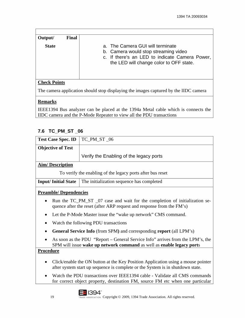
Output/ Final
State
a. The Camera GUI will terminate b. Camera would stop streaming video c. If there's an LED to indicate Camera Power,
the LED will change color to OFF state.
Check Points
The camera application should stop displaying the images captured by the IIDC camera
Remarks IEEE1394 Bus analyzer can be placed at the 1394a Metal cable which is connects the IIDC camera and the P-Mode Repeater to view all the PDU transactions
7.6 TC_PM_ST _06 Test Case Spec. ID TC_PM_ST _06
Objective of Test
Verify the Enabling of the legacy ports
Aim/ Description
To verify the enabling of the legacy ports after bus reset
Input/ Initial State The initialization sequence has completed
Preamble/ Dependencies
• Run the TC_PM_ST _07 case and wait for the completion of initialization se-quence after the reset (after ARP request and response from the FM’s)
• Let the P-Mode Master issue the “wake up network” CMS command.
• Watch the following PDU transactions
• General Service Info (from SPM) and corresponding report (all LPM’s)
• As soon as the PDU “Report – General Service Info” arrives from the LPM’s, the SPM will issue wake up network command as well as enable legacy ports
Procedure
• Click/enable the ON button at the Key Position Application using a mouse pointer after system start up sequence is complete or the System is in shutdown state.
• Watch the PDU transactions over IEEE1394 cable - Validate all CMS commands for correct object property, destination FM, source FM etc when one particular

1394 TA 20093034
20 Copyright © 2009, 1394 Trade Association. All rights reserved.
FM transmit or receive an command Output/ Final
State
Legacy Ports Enabled
SPM has to receive the “Power Status Indication” from all LPM’s
Check Points
Check for the following PDU ‘s at the PMode master
o Reception of completion of initialization sequence completion
o Transmission of wake up the network command to SPM
Check for the following PDU ‘s at the SPM
o Reception of wake up the network from the PMode master
o Soon after receiving this the SPM should issue General Service Info (LPM) to LPM
o SPM should receive “Report – General Service Info” from LPM’s. o When receive the above confirmation the SPM should issue “Wake up
Command” to all LPM’ s o After that the SPM has to issue the command “Enable Legacy Ports”
After this command the SPM has to receive the “Power Status Indication” from all LPM’s
Remarks The legacy device present in this EPoC is the IIDC Camera
7.7 TC_PM_ST _07 Test Case Spec. ID TC_PM_ST _07
Objective of Test Verify the Disabling legacy ports
Aim/ Description To verify operation of disabling all legacy ports in the network
Input/ Initial State The EPoC should be in the woken up state
Preamble/ Dependencies Run test case TC_PM_ST _04 and after this the EPoC should be in the woken up state. (The interface box should be able to send up the PM LINE LOW status at every 8 sec-onds) Procedure

1394 TA 20093034
21 Copyright © 2009, 1394 Trade Association. All rights reserved.
Run the test case TC_PM_ST _04. Click/enable the OFF button at the Key Position Application using mouse pointer Output/ Final
State
Check the color change OFF and ON buttons
All legacy ports are disabled
Check Points
Get ports connected to Legacy Nodes
o PMode master should be able to send the “Shutdown Network” to SPM
o The SPM should be able to receive the above command “Shutdown Network” from PMode master
o Observe the PDU transactions from Shutdown Request to all LPM’s to suspend local Apps in Node as per sequence diagram Figure 1 Se-quence diagram for Cooperative shutdown through Key Position Appli-cation in network architecture document version 0.8.
o After issuing the shutdown execute the SPM should issue the Disable Legacy Ports to CCM
o The CCM will Get ports connected to Legacy Nodes and will disable the port connected to the legacy device
o The legacy device present in this EPOC is the IIDC Camera
7.8 TC_PM_ST _08 Test Case Spec. ID TC_PM_ST _08
Objective of Test
Verify the Shutdown/ sleep functionality of EPoC System
Aim/ Description
To Verify the IEEE1394 sleep functionality by switching the repeater to OFF state by making PM line HIGH (inactive) Input/ Initial State The EPOC system should be in the WAKE UP state
Preamble/ Dependencies
Successful execution of TC_PM_ST _02
Procedure
1. Run the test case for wake up successfully
2. Click/enable the OFF button at the Key Position Application using mouse

1394 TA 20093034
22 Copyright © 2009, 1394 Trade Association. All rights reserved.
pointer 3. Observe the PDU transactions between LPM, SPM, and PMode master,
PMode slave. They are a. Shutdown Network b. Shutdown Request to all LPM ‘s c. Shutdown Accept d. Shutdown Execute e. Suspend Local PHY + Link
Output/ Final
State
1. All legacy ports in the network disabled
2. All local Applications in device and in host Node are Sus-
pended
3. PM Line Deactivated
Check Points
1. Observe the Key Position Application ON and OFF buttons color changes.
2. Check for all legacy ports in the network are in disabled state
3. PM Line Deactivated
4. Check that the PMode slave FM has printed the arrival of “PM deactivated “
5. Check the status of I/F BOX.
6. All the FM’s should exit
Remarks
The IEEE 1394 Protocol analyzer can be make use for the PDU which are mov-ing across the IEEE1394 cable
7.9 TC_PM_ST _09 Test Case Spec. ID TC_PM_ST _09
Objective of Test
Verify the Shutdown/ sleep functionality of EPoC System by
forced method when one or more local power masters
are rejecting the shutdown request.
Aim/ Description

1394 TA 20093034
23 Copyright © 2009, 1394 Trade Association. All rights reserved.
Verify the Shutdown/ sleep functionality of EPoC System Input/ Initial
State
The EPOC system should be in the WAKE UP state
Preamble/ Dependencies
Successful execution of TC_PM_ST _02
Procedure
Procedure Run the test case for wake up successfully
Click/enable the OFF button at the Key Position Application using mouse pointer Observe the PDU transactions between LPM, SPM, and P-Mode master, P-Mode slave. They are
Shutdown Network Shutdown Request to all LPM ‘s Shutdown Accept Shutdown Execute Suspend Local PHY + Link
Output/ Final
State
4. All legacy ports in the network disabled
5. All local Applications in device and in host Node are
Suspended
PM Line Deactivated
Check Points
• Observe the Key Position Application ON and OFF buttons color
changes.
• Check for all legacy ports in the network are in disabled state
• PM Line Deactivated
• Check that the P-Mode slave FM has printed the arrival of “PM deacti-
vated “
• Check the status of I/F BOX.
• All the FM’s should exit
1394 TA 20093034
24 Copyright © 2009, 1394 Trade Association. All rights reserved.
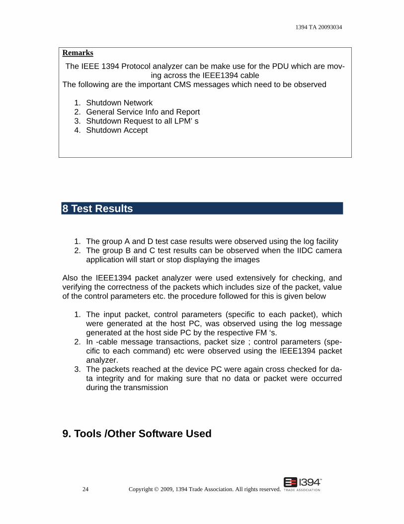
Remarks
The IEEE 1394 Protocol analyzer can be make use for the PDU which are mov-ing across the IEEE1394 cable
The following are the important CMS messages which need to be observed
1. Shutdown Network 2. General Service Info and Report 3. Shutdown Request to all LPM’ s 4. Shutdown Accept
8 Test Results
1. The group A and D test case results were observed using the log facility 2. The group B and C test results can be observed when the IIDC camera
application will start or stop displaying the images Also the IEEE1394 packet analyzer were used extensively for checking, and verifying the correctness of the packets which includes size of the packet, value of the control parameters etc. the procedure followed for this is given below
1. The input packet, control parameters (specific to each packet), which were generated at the host PC, was observed using the log message generated at the host side PC by the respective FM ‘s.
2. In -cable message transactions, packet size ; control parameters (spe-cific to each command) etc were observed using the IEEE1394 packet analyzer.
3. The packets reached at the device PC were again cross checked for da-ta integrity and for making sure that no data or packet were occurred during the transmission
9. Tools /Other Software Used

1394 TA 20093034
25 Copyright © 2009, 1394 Trade Association. All rights reserved.
1. Operating System used on the host and device PC’s are – Redhat Linux 9 (kernel 2.4.20-8)
2. IEEE1394 Bus Analyzer is used for capturing the packets and thus for
validating the correct sequence and transaction of commands with cor-rect values
Table 1 – Hardware Requirements
Item Quantity Resources 1 2 PCs running Linux 9.0 with serial ports and
IEEE1394a ports 2 2 RS 232C cables 3 2 P-Mode I/F BOX 4 3 P-Mode Repeaters 5 Unit tested S/w modules for SPM, LPM, CCM etc 6 2 IEEE1394 Bus Analyzer 7 4 PM & Power cable 8 IEEE 1394 POF Cables 9 1 IIDC v1.02 compliant camera

1394 TA 20093034
26 Copyright © 2009, 1394 Trade Association. All rights reserved.
Annex A Requirement and recommendation language A.1 Requirements The following verbal forms are indicative of requirements that are to be followed in order to achieve conformance to this specification. No deviation is permitted from a requirement. Verbal Form Equivalent Expressions Shall, Must, Will Is to
Is required to It is required that Has to Only … is permitted It is necessary
Shall Not, Will Not Is not allowed [permitted] [acceptable] [permissible]
A.2 Recommendations The following verbal forms are indicative of recommendations or courses of ac-tion that are preferred, but are not necessarily required. Verbal Form Equivalent Expressions Should It is recommended that
Ought to Should Not It is not recommended that May Is permitted
Is allowed Is permissible
May Not Need not It is not required that No … is required
Can Be able to There is a possibility of It is possible to
Cannot Be unable to There is no possibility of It is not possible to

1394 TA 20093034
27 Copyright © 2009, 1394 Trade Association. All rights reserved.
Annex B Request for change form Use this form to identify errors or deficiencies or to recommend general changes. Document No.
Version No.
Version Date
Document Title
Requestor Information Name:
Organization:
E-Mail:
Phone:
Description of Change: Section number:_____________________ Rational for Change: Proposed Revision: Affected Sections: