document resume ce 034 074 antenna … · antenna construction & propagation of. radio waves,...
TRANSCRIPT

DOCUMENT RESUME
ED 222 691 CE 034 074
TITLE Antenna Construction & Propagation of Radio Waves,5-1. Military Curriculum Materials for Vocational andTechnical Education,
INSTITUTION Marine Corps, Washington, D.C.; Ohio State Univ.,Columbus. National Center for Research in Vocational
Education.SPONS AGENCY Office of Education (DHEW), Washington, D.C.PUB DATE 78NOTE 139p.PUB TYPE Guides - Classroom Use - Materials (For Learner)
(051)
EDRS PRICE MF01/PC06 Plus Postage.DESCRIPTORS *Electricity; Military Personnel; Military Training;
Postsecondary Education; *Radio; Secondary Education;*Technical Education
IDENTIFIERS *Antennas; Military Curriculum Project; *Radio Waves;Wave Propagation
ABSTRACTThese military-developed curriculum materials consist
of five individualized, self-pacld chapters dealing with antennaconstruction and propagation of radio waves. Covered in the
individual lessons are the following topics: basic electricity;
antenna transmission-line fundamentals; quarter-wave antennas,half-wave antennAs, and associated radio patterns; long-wire antennasand antenna propagation; and radio wave propagation. Each lessoncontains reading assignments and review exercises. (MN)
***********************************************************************Reproductions supplied by EDRS are the best that can be made
from the original document.***********************************************************************
Mk*
3
.111
1 'T ' IDUCK11011NATIONAk INSTITUTE OF EDUCATION
UCATIONAL RESOURCES tNFORMAMONCENTER (ERIC)
Thie document hes been Nproduced estecenned from the puson or organiution
odokuting it.LI Minor changes how been made to Improve
repoduction filfertfY.
Ponns of view or opinions IWO in this &co
TAM do not necessarily represent officio! NIE
portion or poky.
"PERMISSION TO REPRODUCE THISMATERIAL HAS BEEN GRANTED BY
or A
TO THE CATIONAL RESOURCESINFORMATION CENTER (ERIC)."

MILITARY CURRICULUM MATERIALS
The military-developed curriculum materials in this course
package ware selected by the National Center for Research in
Vocational Education Military Curriculum Project for dissem-
ination to the six regional Curriculum Coordination Centers and
other instructional materials agencies. The purpose of
disseminating these courses was to make curriculum materials
developed by the military more accessible to vocational
educators in the civilian setting.
The course materials %ere aoguired evaluated by project
staff and practitioners in the field, and prepared for
dissemination. Materials which were specific to the nilitary
were deleted, copyrighted materials were either omitted or appro-
val for their use %es obtained. These course packages contain
curriculum resource materials which can be adapted to support
vocational instruction and curriculum development.

The National CenterMission Statement
--=.7"."37 ,
. .
The National Center for Research inVocational Education's mission is to increasethe ability of diverse agencies, institutions,and organizations to solve educational prob-lems relating to individual career planning,preparation, and progression. The NationalCenter fulfills its mission by:
Generating knowledge through research
Developing educational programs andproducts
Evaluating individual program needsand outcomes
Installing educational programs andproducts
Operating information systems andservices
Conducting leadership development andtraining programs
FOR FURTHER INFORMATION ABOUTMilitary Curriculum Materials
WRITE OR CALLProgram Information OfficeThe National Center for Research in Vocational
EducationThe Ohio State University1960 Kenny Road, Columbus, Ohio 43210
4Telephone: 61414863655 or Toll Free 800/
848.4815 within the continental U.S.(except Ohio)
Military CurriculumMaterials for
Vocational andTechnical Education
Information and FieldServices Division
The Nation:II Center for Researchin Vocctional Education
: 5

MilitaryCurriculum MaterialsDissemination Is . a .
an activity to incease the accessibility ofmilitary.developed curriculum materials tovocational and technical educators.
This project, funded by the U.S. Office ofEducation, includes the identification andacquisition of curriculum materials in printform from the Coast Guard, Air Force,Army, Marine Corps and Navy.
Access to military curriculum materijk: isprovided through a "Joint Memorandm ofUnderstanding" between the U.S. Office ofEducation and the Department of Defense.
The acquired materials are reviewed by staffand subject matter specialists, and coursesdeemed applicable to vocational and tech-nical education are selected for dissemination.
The National Center for Research inVocational Education is the U.S. Office ofEducation's designated representative tocquire the materials and conduct the project
activities.
Project Staff:
Wesley E. Budke, Ph.D., DirectorNational Center Clearinghouse
Shirley A. Chase, Ph.D.Project Director
What MaterialsAre Available?
..t . . '..." ba...3.411A.Uarilk.11:1A4.441
One hundred twenty courses on microfiche(thirteen in paper form) and descriptions ofeach have been provided to the vocationalCurriculum Coordination Centers and otherinstructional materials agencies for dissemi-nation.
Course materials include programmedinstruction, curriculum outlines, instructorguides, student workbooks and technicalmanuals.
The 120 courses represent the followingsixteen vocational subject areas:
AgricultureAviationPuilding &
ConstructionTrades
ClericalOccupations
CommunicationsOral tingElectronicsEngine Mechanics
Food ServiceHealthHeating & Air
ConditioningMachine ShopManagement &
SupervisionMeteorology &
NavigationPhotographyPublic Service
The number of courses and the subject areasrepresented will expand as additional mate-rials with application to vocational andtechnical education are identified and selectedfor dissemination.
How Can TheseMaterials Be Obtained?
"" :jr. ,
Contact the Curriculum Coordination Centerin your region for information on obtainingmaterials (e.g., availability and cost). Theywill respond to your request directly or referyou to an instructional materials agencycloser to you.
CURRICULUM COORDINATION CEN FERS
EAST CENTRALRebecca S. Douglass
Director100 North First StreetSpringfield, IL 62777217/782-0759
MIDWESTRobert PattonDirector1515 West Sixth Ave.Stillwater, OK 74704405/377 .2000
NORTHEASTJoseph F. Kelly, Ph.D.
Director225 West State StreetTrenton, NJ 08625609/292.6562
NORTHWESTWilliam DanielsDirectorBuilding 17Airdustrial ParkOlympia, WA 98504206/753.0879
SOUTHEASTJames F. Shill, Ph.D.DirectorMississippi State University
Drawer DXMississippi State, MS 39762
601/325.2510
WESTERNLawrence F. H. Zane, Ph.D.
Director1776 University Ave.Honolulu, HI 96822808/948.7834
7

Correspondence Course 5-1
ANNTENNA CONSTRUCTION AND PROPAGATION OF RADIO WAVES
Table of Contents
Course Description Page 1
Lesson Assignments and Questions Page 3
Antenna Construction and Propagation ofRadio Waves MC1 25.15b
Chapter 1 - Basic Electricity
Chapter 2 - Antenna and Transmission LineFundamentals
Chapter 3 - Quarter-Wave, Half-WaveAntennas and Associated RadiationPatterns
Chapter 4 - Long-Wire Antennas and AntennaInstallation
Chapter 5 - Radio Wave Propagation
Page 26
Page 36
Page 54
Page 79
Page 112

- ANTENNA CONSTRUCTION AND PROPAGATION
OF RADIO ,WAVES
..-
(4....."
Corresponduce Course
/5-1
Developed by;
United States Marine Corps
Development andReview Dates
April 1975
Occupational Arm:
Communications
Cos: Print Pages:
1131
Availability:Military Curriculum Project, The Centerfor Vocational Education, 1960 KennyRd., Columbus, OH 43210
Suggested Background:
None
Tweet Audiences:
- Grades 10-adult
Organization of Materials:
Student lesson book with assignments and review exercises; text readings
Type of Instruction:
Individualized, selfpaced
Type of Materials:
Antenna Construction and Propagation of Radio Waves
No. of Pages: AverageCompletion Time:
Lesion 1 Basic Electricity 10 Flexible
Lesson 2 Antenna and Transmission Line Fundamentals 18 Flexible
Lesson 3 Ouarter-Wave, Half-Wave Antennas andAssociated Radiation Patterns 25 Flexible
Lesson 4 Long-Wire Antennas and Antenna Propagation 38 Flexible
Lesson 5 Radio Wave Propagation 20 Flexible
Student Lesson Book 19
,
Supplemontary Materials Required:
None
cern' WI VOCAIIPW MOM14 FMK, %IMO' %/WV t., Hr.! 9 Expires July 1, 1978

INNIIM10Course Description:
This course is designed to provide the studs% with the fundamentals of electricity, antenna construction, and wave propagation. It provides the theorybeckground for using wave propagation in communication. The course consists of five lessons.
Lesson I
Lessan 2
Lesson 3
Basic Electrici has an introduction to electricity, and covers the composition of matter, conductors and insulators, basiclaws, electric current, electromotive force, resistance, magnets, the nature of magnetism, and elec .ric symbols.
Antenna and Transmission Line Fundamentals discusses the electromagnetic field, antenna theory, radiation, graphs,polarization, antenna input impedance, transmission line theory and the types of transmission line.
QuarterWave, half-Wave Antennas and Associated Radiation Patterns contains two sections. Section I describes whip(Marconi), ground plane, bent, folded-top, top-loaded, and tower radiated antennas. Section II discusses Her% groundaffected radiation patterns, single wire antennas, folded dipole, coaxial, conical and microwave antennas, and multielement arrays.
Lesson 4 Long-Wire Antennas and Antenna installation contains two sections. Section I describes the general characteristics of long-wireantennas, harmonically operated antennas in free space, end feeding long-wire antennas, resonant and nonresonant antennas,beverage or wave antennas, V antennas, half-rhombic antennas, and rhombic antennas. Section II covers site selection forInstallation, safety precautions, grounds and counterpoises, orientation, profiles, and field expedient methods.
Lesson 5 Radio Wave Propagation contains three sections. Section I discusses general propagation factors. frequency spectrum, theatmosphere, and wave bending. Section II discusses general ground wave propagation. composition and characteristics ofground wave propagation, and tropospheric propagation. Section III discusses general sky wave propagation. the ionsphere,ionsphere characteristics, transmission paths, and frequency prediction.
Each lesson contains reading assignments and review exercises, but objectives and answers to the exercises are not given. The ;our se is designed for studentself-study. It can be used as a sub-unit in electrical communications.
-
larnigIn Al'ilr4WVERSSI 1. 0

UNITED STATES MARINE CORPSMARINC CORPS INSTITUTE. MANNIC SARRACKS
SOS 1773WASHINGTON. D.C. 20013
ANTENNA CONSTRUCTION AND PROPAGATION OF RADIO WAVES
Lesson 1
Basic Electricity
25.15b
-.......2...
STUDY ASSIGNMENT: Information for MCI Students.Course Introduction.MCI 25.15b, Antenna Construction and Prooa ation of Radio Waves chap I.
WRITTEN ASSIGNMENT:
A. Multiple Choice: Select the ONE answer which BEST completes the statement or answersthe question. After the corresponding number on the answer sheet, blacken the appropriatebox.
Value: 1 point each
1. A compound will retain its characteristics after it has been subdivided into
a. atoms.b. molecules.
2. The atomic nucleus is composed of
c. protons.d. electrons.
a. atoms and molecules. c. neutrons and protons.b. neutrons and electrons. d. protons and electrons.
3. What prevents the electrons from being drawn toward the nucleus?
a Electrical repulsionb. Centrifugal force
4. The atom is the smallest particle of
c. Atomic weightd. Centripetal force
a, a molecule. c. a proton.b. an element. d. an electron.
5. An atom is said to be ionized if it has gained or lost one or more of its
a. protons.b. electrons.
c. neutrons.d. positrons.
6. When an atom is excited, free electrons are liberated from the
a. nucleus.b. inner planetary orbit.
7. Current flow is caused by the movement of
c. central planetary orbit.d. outer planetary orbit.
a. free electrons. c. molecules.b. atoms. d. protons.
8. A good conductor is
a. glass.b. rubber.
lsn 1; p. 1
11
c. dry wood.d. aluminum
3

9. A good insulator is
a. copperb. brass
c. mica.d. aluminum.
10. Assume that you have generated a static charge by rubbing a comb with a woolen cloth.If the comb is negatively charged, the woolen cloth has
11.
a. lost electrons.b. gained electrons.
c. lost protons.d. gained protons.
According to the law of like and unlike charges, the protons within the nucleus of theatom must
a. absorb electrons.b. neutralize each other.
c. repel each other.d. attract each other.
12. Two charged bodies are 1 inch apart. What Is the force of attraction or repulsion If onebody has a charge of 2 coulombs and the other, a charge of 3 coulombs?
a. 1 newtonb. 1.5 newtons
C. 5 newtonsd. 6 newtons
13. Refer to question 12. What is the force of attraction or repulsion if the distance be-tween the two charged bodies is increased to 2 inches?
a. 1 newtonb. 1.5 newtons
c. 5 newtonsd. 6 newtons
14. The field of force between charged bodies is called
a. a neutral field.b. an electrostatic field.
c. a magnetic field.d. an artificial field.
15. Electrons are held in orbit by the attraction of the in the nucleus.
a. protonsb. neutrons
c. positronsd. molecules
16. What is the practical unit for measuring an electrical charge?
a. Ohmb. Volt
c. Coulombd. Ampere
17. What is the direction of the electric field between positive and negative cha:ges?
a. Positive to negativeb. Negative to positive
18. The direction of electron flow in a conductor
a. positive to negative.b. negative to positive.
19. Unit current flow is expressed in
a. amperes.b. volts.
20 Identify the force that produces current flow
a. Electrostatic forceb. Artificial force
c. Positive to positived. Negative to negative
is from
c. positive to positive.d. negative to negative.
c. ohms.d. newtons.
in a conductor.
c. Electromotive forced. Magnetic force
21. The unit of measure for the opposition to current flow is called a(an)
a. coulomb.b. amp.
25.15lain 1; p. 2
1 e
c. volt.d. ohm.
If

22. Which symbol designates opposition to current flow?
a. Eb. 0
c. Rd. I
23. An increase in temperature will cause the resistance of a copper conductor to
a. increase. b. decrease. c. remain the same.
24. Where does a bar magnet exhibit maximum attraction?
a. At its center c. Along its surfacesb. At its ends d. Along its edges
25. What are the three groups of magnets?
a. Natural, permanent, and electromagnetsb. Artificial, permanent, and electromagnetsc. Bar, permanent, and naturald. Artificial, natural, and electromagnets
26. According to Weber's theory, the molecules of an unmagnetized substance are arrangedso that their poles sre
a. alined. c. staggeredb. opposed. d. distributed at random.
27. Support for Weber's theory is found in the fact that when a permanent magnet is brokeninto several pieces,
a. they repel each other.b. each piece has a north and a south pole.c. they are demagnetized.d. they distribute themselves at random.
28. Inside the magnet, magnetic lines of force pass from the pole to the pole.
a. south--southb. north--north
29. Magnetic lines of force act so as to
a. cross at the poles.b. repel each other.
c. south--northd. north--south
c. merge at the poles.d. attract each other.
30, If the distance between two north poles is increased from 4 inches to 8 inches, the forceof repulsion between them is to its original value.
a. decreasedone-fourth c. decreased--one-halfb. increasedfour times d. increased--twice
31. The space surrounding a magnet is called a(n)
a. natural field. c. artificial field.b. magnetic field. d. neutral field.
25.15lsn 1; p. 3
Total Points: 31
* * *
13

UNITED STATES MARINE CORPSMARINE CORPS INSTITUTE. MARINE BARRACKS
BOX 1775WASHINGTON. D.C. 20013
25. 15b
(0
ANTENNA CONSTRUCTION AND PROPAGATION OF RADIO WAVES
Lesson 2
Antenna and Transmission Line Fundamentals
STUDY ASSIGNMENT: MCI 25.15b, Antenna Construction and Propagation of Radio Waves, chap 2.
WRITTEN ASSIGNMENT:
A. Multiple Choice: Select the ONE answer which BEST compleies the statement or answAlsthe question. After the corresponding number on the answer sheet, blacken the appropriatebox.
Value: 1 point each
1. The magnetic field around a conductor is produced by
a. resistance.b. voltage.
Note: Questions 2 through 5 refer to this diagram.
c. inductance.ci. current.
2. The direction of the magnetic field surrounding conductor ABCD is from point
a. B to point C. c. H to point E.b. C to point B. d. F to point E.
3. Assume that a compass is placed in the field surrounding conductor BC. The needle ofthe compass will be alined so that its pole faces point , and its polefaces point .
a. north--E--south--F c. north- -E - -south - -Hb. south - -E - -north- -F d. south--G--north--H
4. If the current flow is doubled, the strength of the magnetic field at point G will increasetimes.
a. 2
b. 3
len 2; P. 1
c. 4d. 8
14

5. I! point F is moved twice as far from the conductor, the strength of the magnetic fieldwill decrease to
a. 112. c. 1/4.b. 113. d. 1/8.
6. The combined electric and magnetic field is called the
a. electrostaticb. electromagnetic
C.d.
field.
electric-magneticinduction
7. When the electric field about a conductor carrying alternating current is maximum,the magnetic field is
a. decreasing.b. increasing.
C.d.
maximum.minimum.
8. In geometric terms the two fields composing the electromagnetic field areeach other.
a. parallel c. complementaryb. perpendicular d. coefficient
9. At what speed do radio waves travel?
a. 720 feet/sec C.
b. 1,100 feet/sec d.186,000 miles/sec300,000 miles/sec
10. What is the wavelength, in meters, of an antenna operating at 60 Megahertz ?
a. 0.78 c. 7.8b. 5 d. 50
to
11. What is the physical length, in feet, of a half-wave antenna operating at 60 Megahertz?
a. 0.78b. 5
c. 7.8d. 50
12. The formula for finding the wavelength of an antenna is
a. 3000f .
b. 300000f .
c. 3000000f .
d. 300000000f .
13. By attaching two one-quarter wavelength conductors to an RF generator we constructthe basic antenna known as the antenna.
a. whipb. long-wire
c. dipoled. rhombic
14. One characteristic of a dipole antenna is that its
a. voltage Is maximum at the center. c.b. current is maximum at the center. d.
15. An "E" energy loop that has broken away from anMan) field.
current is minimum at the center.voltage is minimum at the ends.
antenna is repelled into space by
a. collapsing "E" c. expanding "E"b. collapsing "H" d. expanding "H"
25.15lsn 2; p. 2

16. A radiator that emits stronger radiation in one direction than another is called
a. isotropic.b. omnidirectional.
c. anisotropic.d. bidirectional.
17. A radiation pattern is defined as the measurement of energy, taken at angle(s)and at distance(s) from the antenna.
a. a constanta constant c. various--a constantb. a constant--various d. variousvarious
18. A source of radiation is classified as being either Or
a. horizontal--vertical c. polar--rectangularb. isotropicanisotropic d. concentric--eccentric
19. A characteristic of a polar-coordthate graph is
a. the antenna is located at the side.b. lobes and nulls are not shown.c. it shows the non-direction of radiated energy.d. the antenna is located at the center.
20. The radiation pattern of a dipole antenna has
a. 1--1b. 2-2
c. 1--2d. 2--1
lobe(s) and null(s).
21. Which component(s) of a radiated wave determine(s) its polarization?
a. "E" field b. "H" field c. "E" and "H" fields
22. The ratio of voltage to current at a point on the antenna is used to determine the antenna's
a. radiation resistance. c. input impedance.b. reactance. d. power loss.
23. The equivalent circuit of a transmission line consists of resistance, inductance, and
a. reactance. c. impedance.b. capacitance. d. radiation.
24. A characteristic impedance of an infthitely long transmission line is the impedancewhich is
a. "seen" by tne transmitter, c. measured at any point on the line.b. "seen" by the antenna. d. equivalent to all of the above.
25. When the antenna impedance is greater than the 20 of the transmission line, it appearsas a(an)
a. open circuit. c. inductance.b. short circuit. d. pure resistance.
26. When the antenna impedance is less than the 20 of the transmission li.ie, it appearsas a(an)
a. open circuit. c. inductance.b. short circuit. d. pure resistance.
25. 15lain 2; p. 3
16
8

27. What type transmissioa line is most desirable for high-frequency applications?
a. Coaxialb. Shielded-pair
c. Twisted-paird. Parallel 2-wire
28. What type transmission line is generally used for low-frequency applications at shortdistances?
a. Coaxial c. Twisted-pairb. Shielded-pair d. Parallel 2-wire
Total Points; 28
* * *
25. 15lsn 2; p. 4
9

25.15bUNITED STATES MARINE CORPS
MARINE CORPS INSTITUTE. MARINE SARRACKSSOX ITTS
WASHINGTON. D.C. 20013
I 0
ANTENNA CONSTRUCTION AND PROPAGATION OF RADIO WAVES
Lesson 3
Quarter-wave, Halfwave Antennas and Associated Radiation Patterns
STUDY ASSIGNMENT: MCI 25.15b, Antenna Construction and Pro a ation of Radio Waves chap 3.
WRITTEN ASSIGNMENT:
A. Multiple Choice: Select the ONE answer which BEST completes the statement or answersthe question. After the corresponding number on the answer sheet, blacken the appropriatebox.
Value: 1 point each
1. A whip antenna acts as a half-wave antenna because
a. it has two sections.b. it is vertically polarized.c. the ground shorts out the electric field.d. the ground takes the place of the missing quarter-wavelength.
2. The quarter-wave antenna is known as the antenna.
a. Hertzb. Marconi
c. doubletd. harmonic
3. Maximum radiation produced by a quarter-wave antenna is best described as
a. unidirectional. c. parallel to the antenna.b. bidirectional. d. perpendicular to the antenna.
4. The vertical pattern of the whip antenna resembles the figure eight because
a. it acts as a half-wave antenna. c. there is no radiation from its ends.b. it acts as a full-wave antenna. d. there is no radiation from its center.
5. The ground plane antenna is classed as a antenna.
a. quarter-wave c. full-waveb. half-wave d. multiple-wave
6. Maximum radiation produced by the ground plane antenna occurs at a vertical angle ofdegrees.
2. zerob. 45
c. 90d. 120
7. To obtain maximum radiation in the horizontal direction, you bend the spokes of theground plane antenna to an angle of below the horizontal plane.
a. 15o c. 500b. 300 d. 65°
lsn 3; p. 1
18

8. The ground plane antenna is a whip antenna With a/an
a. ground rod.b. effective artificial ground.
c. elaborate counterpoise.d. buried radial system.
Questions 9 through 12 refer to the antenna illustrations.
3.
9. Bent antenna
a. 3 b. 6
10. Folded-top antenna
a. 2 b. 3
11. Top-loaded antenna
a. 6 b. 5
12. Tower radiated antenna
a. 1 b. 3
c. 5
c. 4
d. 4
d. 5
c. 4 d. 2
c. 4
13. The inverted-L antenna is particularly useful for propagation.
a. ground wave c. ductb. sky wave d. troposcatter
25.15Ian 3; p. 2

1 2..
14. Radiation produced by an inverted-L antenna is that produced by a whip antenna ofthe same height.
a. less than b. greater than c. equal to
15. We fold the flattop of a bent antenna to
a. produce unidirectional radiation. c. produce current flow in one section only.b. prevent ground currents. d. prevent horizontally polarized radiation.
16. How does top-loading affect the vertical antenna?
a. Decreases radiation resistanceb. Prevents harmonic radiation
c. Increases the effective lengthd. Produces unidirectional radiation
17. What type of feeding is used with a noninsulated tower radiator?
18.
19. A Hertz antenna consists of two conductors, each being a in length.
a. full-wave b. half-wave c. quarter-wave
20. What is the direction of maximum radiation produced by the Hertz antenna?
a. Regenerative c. Shuntb. Degenerative d. Series
What type of antenna is the Hertz?
a. Quarter-wave c. Full-waveb. Half-wave d. Multiple-wave
a. Upward at vertical angle to plane of antennab. Along the earth's surfacec. Parallel to the antennad. Perpendicular to the antenna
21. A ground on an antenna can have the effect of either being
a. good or poor. b. excellent or fair. c. good or excellent.
22. A ground affected radiation pattern has a maximum reflection factor value of
a. 1 c. 3
b. 2 d. 4
23. If a horizontal Hertz antenna is located a half-wavelength above ground, and the vertical.angle is 30°, what is the reflection factor?
a. 0 c. 1.75b. 1 d. 2
24. When a horizontal half-wave antenna is mounted 2 wavelengths above ground, how manyvertical lobes are produced?
a. 2 c. 6
b. 4 d. 8
25. A single-wire half-wave antenna Is constructed of a single conductor wire of proper lengthand may be polarized either
a. electrically or manually. c. as a stationary or mobile antenna.b. vertically or horizontally.
25.15lsn 3; p. 3
20

---
26. What type of antenna is formed by adding additional elements in parallel with a half-waveantenna?
a. Coaxial c. Folded-dipoleb. Inverted-L, : Single-wire
27. What component(i) of the coaxial antenna should be adjusted to change the frequency ofoperation?
a. Whipb. Skirt
c. Either of the aboved. Both of the above
28. Why is a simple half-wave antenna seldom used in the microwave range?
a. Size Is too great.b. Signal pickup is poor.
c. Radiation resistance is too high.d. Reflection factor is poor.
The antenna illustrations refer to questions 29 through 32.
Im
I1
£410/1TI4te PORTONSo IMP
MNOToo CLUI
MC* PSITIOSOP woo
IsosP il SOCKS TOWIT aelessftir ATfist PIM
NSAITOS
sCe1TM41 Wes CT
INIONNII Roo,
PIM PCOTIOSCO VONT
ANATsof ',AMP
AMSTSIA PCO1104OP SztAT
~MOS $TIPP
1101CU11 PON IMPS,*UIT1Ns TO rST
imblatClUS IHOSN4
KAMM. OKI
1
TsoloSSOO1Use
2
29. Microwave antenna
a. 4 b. 3
30. Conical antenna
a. 1 b. 2
31. Folded-dipole antenna
a. 1 h. 2
32. Coaxial antenna
a. 4 b. 3
25.15lsn 3; p. 4
Total Points: 32
f
.... i
c. 2
c. 3
4
3
d. 1
d. 4
c. 3 d. 4
c. 2 d. 1
21

25.15b
uNrreo STATES MARINE CORPSMARINE CORPS INSTITUTE. MARINE 'BARRACKS
SOX 1775WASHINGTON. D.C. 20013
ANTENNA CONSTRUCTION AND PROPAGATION OF RADIO WAVES
Lesson 4
Long-Wire Antennas and Antenna Installation
STUDY ASSIGNMENT: MCI 25.15b, Antenna Construction and Propagation of Radio Waves,chap 4.
WRITTEN ASSIGNMENT:
A. Multiple Choice: Select the ONE answer which BEST completes the statement ar answersthe question. After the corresponding number on the answer sheet, blacken the appropriatebox.
Value: 1 point each
1. What is the length of a long-wire antenna?
a. Quarter-wavelengthb. Half-wavelength
c. Shorter than a half-wavelengthd. Longer than a half-wavelength
2. Two advantages long-wire antennas have over other antennas are
a. construction and maintenance.b. polarization and construction.
c. directivity and polarization.d. gain and directivity.
3. A long-wire antenna that has two or more half-waves of energy distributed along it iscalled a antenna.
a. Marconib. Hertz
c. harmonicd. nonharmonic
4. What is the length, in feet, of a 2-wavelength harmonic long-wire antenna operating at20 MHz?
a. 23.985b. 47.97
c. 48.585d. 93.48
5. What is the length, in feet, of a 1-wavelength harmonic long-wire antenna operating at30 MHz?
a. 15.246b. 30.493
c. 60.986d. 91.079
6. A current-fed antenna behaves as a true long-wire only at odd harmonics of the originalfrequency. Therefore, for operation on all harmonics, the best type of feeding is at the
a. center of the antenna. c. end of the antenna.b. odd harmonic on the antenna.
7. U one end of an antenna is terminated in a resistance that is equal to the characteristicimpedance of the antenna, waves can travel in one direction only and no standing wavesare set up. This type antenna is known as a antenna.
a. resonant
lsn 4; p. 1
b. nonresonant c. matching
22
1 g
8. An antenna that is directional and is used primarily for either transmitting or receivinglow-frequency signals is the antenna.
a. Beverage b. conical c. coaxial
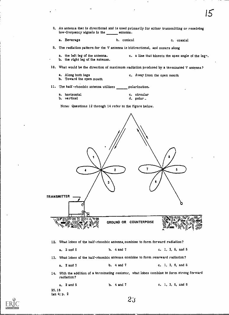
9. The radiation pattern for the V antenna is bidirectional, and occurs along
a. the left leg of the antenna.b. the right leg of the antenna.
c. a line that bisects the apex angle of the ler.
10. What would be the direction of maximum radiation produced by a terminated V antenna?
a. Along both legsb. Toward the open mouth
e. Away from the open mouth
11. The half -rhombic antenna utilizes polarization.
a. horizontalb. vertical
c. circulard. polar _
Note: Questions 12 through 14 refer to the figure below.
TRANSMITTER
;740,111\-,_ ; \II .N 416 ; /my GROUND OR COUNTERPOISEvv=v11.7Z.11/
-flamtly*
12. What lobes of the half-rhombic antenna.combine to form forward radiation?
a. 2 and 5 b. 4 and 7 c. 1, 3, 6, and 8
13. What lobes of the half-rhombic antenna combine to form rearward radiation?
a. 2 and 5 b. 4 and 7
14. With the addition of a terminating resistor,radiation?
a. 2 and 525.15lsn 4; p. 2
c. 1, 3, 6, and 8
what lobes combine to form strong forward
b. 4 and 7 c. 1, 3, 6, and 8
.1.lae

15. A rhombic antenna consists of
a. 1 half-rhombic mounted vertically.b. 2 long-wire V antennas mounted vertically.c. 3 conductors joined together in the shape of a triangle.d. 4 conductors joined together in the shape of a diamond.
16. What is the direction of maximum radiation produced by the rhombic antenna?
a. At a vertical angle above the horizontal planeb. Perpendicular to the antennac. Parallel to the antennad. Along the earth's surface
17. A standard design rhombic antenna for military application operates in a frequency rangeof
a. 2 to 30 MHz. c. 4 to 30 MHz.b. 4 to 22 MHz. d. 2 to 22 MHz.
18. To obtain desirable antenna sites, planning should always be preceded by a careful study ofterrain maps and, whenever possible, by reconnaissance. Factors to be considered aresize, availability, and
a. accessibility to the site.b. location of the message center.
c. drainage.
19. Increased distances can be covered when an antenna is located so that it overlooks
a. dry ground.b. rocky terrain.
c. water areas.d. heavy foliage.
20. A 30-foot antenna tower should be located at least feet from powerlines.
a. 30 c. 90b. 60 d. 120
21. To electrically raise the ground for use in transmitting radio waves a is used.
a. ground rodb. counterpoise
c. salt solutiond. saltpeter solution
16
22. The long-wireIV, half- and full-rhombic antennas produce a radiation pattern that composesa relatively narrow beam. For maximum performance and efficiency, they require accurate
a. erection.b. orientation.
c. mechanical stability.
23. Two radio stations, each having a 32-foot antenna, could cover a maximum distance ofmiles.
a. 8 c. 32b. 16 d. 64
25.15lsn 4; p. 3
24

Note: Before you answer question 24 refer to the contour map below. Plot its profileson the linear graph paper provided (next page) and apply the elevation correctionslisted in table 4-1. in your MCI textbook.
92 V v0 CONTOUR iNTERVAL i0OfILT
ult.CS
24. Refer again to the contour map above. Assume that two alternate transmission pathsare proposed: point X to point A, and point X to point B. Fifty-foot antennas are utilized.Accordingly your plot of the profiles should show that
a. both paths are unobstructed.b. only the path from point X to A is unobstructed.c. only the path from point X to B is unobstructed.d. both paths are obstructed.
B. Identification: The pictures of the field expedient antennas refer to questions 25 to 28. Identify
the field expedient antenna by selecting the correct illustration. After the corresponding numberon the answer sheet, blacken the appropriate box.
Value: 1 point each
1 WV
Nal no,
z
25.15lsn 4 ; p. 4
Total Points: 28
* * *
25. Vertical antenna
26. Long-wire antenna
27. Half-rhombic antenna
28. Vertical half-wave antenna
(Plus 1 piece of graph paper)

11
11111111111111111111mommammunaissammassamissmatmommammillmmompummilmmommounimmingamommo mon
IMUMMUMKUSUMBERSIOROURARMSEKKORMERMINIUMUUMMENOMMEMMEMUMMORWM
IIIIIIIIIIIIIIIIIIIIIIIIIIII:IIIIIIIIIIII/IIIIIIIIIIIIIIIIIIIIIIIIIIIImaimsmintsupassaimmatimammmamma sumo mansimmmum Wilimmommomm. mimmummmaMEMOMOMMUMIUMUMINUMMEMMIIMMMS MMEMMOMMRERMSOMMESMEMMOMMOMMX MMEOMMERMMMUMMIMEMOSOMMEMESMUMMIMESUM-MMEMMEMINIMMUMSOUBSIMBESSMIMMIMMEMMENIMEM
NUM NUMISMUUMUMERNEMMURSRIMMEMMUMIREMKRUMMEMINIMOSOMMEMMESUMMOMOMMSNERIIUhIIIIIIIIIIllIIIIIllhIIIIIIIIIIIIIIIIIIIIIIilhIIIIIIIIIIIllhIIII
Munn ammassimmassamummaslissmasammissommassmimaimutremormisimmuumMums1111111111111111111111111111111111111111111111111111111111111111111111MUMMOOKOMMUMMEMMEOMMEMEMMOMMUOMMUMMEMMEMMEMMOMMEMUMMUMMERMOSEMOMENNM
UMUUMMMUMISMUOMMUMMUSOIMESUMMEMIMMUURROMUMEREMEMMEMMOROOMMIMOMMEMMENEWassammannumassmisamismumarammumumummummilimmmumissmommmummulassommummassammmonsismsamissamsmismslimmumssmulismalloommnimummwoommmummEmmommimmossommalimmassalpammismamSamommaammalitummUlimminnommommilmommulimmonSMUNIMMUMMEMEMMOISMEKOMMUMMERREEMMUMMEMMERMMOMMUMMMOMIONMEMSEMEMMEMORMI
nommosmismommonampusimminimmismummimMumusinumminialimmmummamminammigsssammsmamilmatiampusxmassamissmommammagnammumummilmmMannummummismom111111111191111111111111111111111111111111111111111111111111111111111assamamma.sassamssimmansamssmummaimuslassimamminmemmummanommammummorm Ems.MMOOMORMUSSMSBMNRIMERMEMMUMMUMMOSIUMMERSISMEMOROORKSIOMMEMEMONSMUMMUMUMOSAMOURBURXEMIUMMUMUMMUMMUMUNKMMUMOMMEMOMMUMEXIMMEMIMMOIMOIMsamminaniummummOommarmanamUmmasmammtmomummummammammummourmlimmemsminannalummulimmuminsumassummisiamammomminsUmmmummmummomSommumumonsmimmsammumnsmagionammuumnsmalisammusommummanammommummummmommummummilmemsmamMESUMMUMMINAMISMURIMOUSEMUSIBUSSMUSSUMMIXIMMMESUMMIMOMMSEMERRIMEMMKUME11111111111199111111111111111111111111111111111111111111111111111111MEMOMMUOMUMUM MUMMMUSUMS MMUMUMUMMOMMEMERMMUMMEMMEIRMOMMORNMEKMEMEMSIIIIIIIIIIIIIIIIIIIIIIIII 1111111111111111111111111111111111111111111
UMOMMIUMBREMEMOUSU usammaammtammusimmmummillimmummommummommwmaniummasammasomessmum manammummilommommummomminimmommaimmimmusmoullimsasammussassimmummossaussasonlawitammummulimmumummommummlimammommomMIN1111111111111111111111111111111111111111111111111111111111111111111111
1111111111111111111111111111111111111111111111111111111111111111111111sassisammummessammassimmonsmastammarmmisomXpammommommisomommommommEng11111111111 11111111111111111111111111111111111111111111111111111Milliiiall11111115111111111111111MMISIIIIIENIMMINIIMIMMIIIIIIIIII111111111111111111111111U1111111111111.111111111111111111111111111111MINNIMMIIIIIMIMINSIIIMMEMINIIMMAR1111111MsammmisammmossauiRs.11111111111 111111111111 111111111111111111111111111111111111111111111111111111111111111111111111111111111111111111111111111111111111111111
11111111111111!111 11111111111111:1111111111111 1111111111111111111111emssommsensorm ilimmiummonsmommilamilimmirommummsammommemummummongsmommill
IIIIIIIIIIIIIIIIIIIIIIIIIIII IIIIIIIIIIIIIIIIIIIIIIIIIIIIIIIIIII1ismassmassammainsammansimsommumnsmommommismiummommarnmst MmalmmusinuMsmannammusamsnassammummuxammummassmallammumEmmummommoniummilmiumuMMIIMM
::::nommusimaseniOaramma*MinsiniummummilmmimmilmmammiummummummiossmommansemismalmutalmissimmulatimmummilummismoussimmammmummommommEmon::::massoginsonnassamossannsammmissammuntmommaglowsmossommEmmunomEmms.anniummmummommemmiumannumumapsommanammmummummommummimmostammmlmmumm
1111111111111111111111111111111111111iIIIIIIIIIIIIIIIIII
olIIIIIIIIIIIIII:IIIIII.................................,....................................
25.15*1. 1; p. 5
26

19
25.15b
UNITED STATES MARINE CORPSMARINE CORP5 INSTITLITS. MARINE SARRACKS
SOX 1775WASHINGTON. D.C. 20013
ANTENNA CONSTRUCTION AND PROPAGATION OF RADIO WAVES
Lesson 5
Radio Wave Propagation
STUDY ASSIGNMENT: MCI 25.15b, Antenna Construction and Propa ation of Radio Waves, chap 5.
WRITTEN ASSIGNMENT:
A. Multiple Choice: Select the ONE answer which BEST completes the statement or answers thequestion. After the corresponding number on the answer sheet, blacken the appropriate box.
Value: 1 po"at each
1. The effect of the atmosphere on radio waves taxies with the of the transmitted wave.
a. type of modulation c. amplitudeb. polarization d. frequency
2. What frequency range, in Megahertz, is covered by vhf?
a. Below 0.03 c. 30 to 300b. 3.0 to 30 d: 300 to 3,000
3. The three regions of the earth's atmosphere arc troposphere, stratosphere, and
a. ';etstream. c. isothermal.b. ionosphere.
4. The stratosphere is lolated between miles from the earth.
a. 0-7b. 7-18
c. 18-30cl. 30-100
5. A smooth surface with good electrical conductivity will act as a(an)
a. reflector. c. diffractor.b. refractor, d. insulator.
6. The angle of incidence of a radio wave is equal to the angle of
a. refraction. c. di:fraztion.b. reflection.
7. In its paths of travel, the radio wave is altered by reflection, refraction, and
a rain. c. diffraction.b. wind. d. deflection.
8. A ground wave is composed ot a surface wave, a ground-reflected wave, a direct wave, anda(an)
a. ionospheric wave. c. troposcatter wave,b. tropospheric wave. d. stratospheric wave.
lan 5; p. 1 27

9. The field intensity of the ground wave depends on these factors: climatic conditions, nature ofthe transmission path, and the
a. mineral properties of the terrain.b. reflection of the earth's curvature.c. characteristics of transmitting the radio wave.
10. 'The ground-reflected .wave has a phase reversal of approximately
a. 45°. C. 1800.b. 900. d. 3600.
11. What method of polarization is best for surface wave transmission?
a. Verticalb. Horizontal
c. Polard. Circular
12. Which condition causes refraction of a tropospheric wave?
a. Temperature changes c. Conductivityb. De-ionization
13. At frequencies above 30 Megahertz, which ground wave component provides the best means ofcommunication?
a. Troposphericb. Ground-reflected
c. Directd. Surface
14. Which band of frequencies is used for transoceanic communication? ,
a. Vhfb. Hf
c. Mfd. Lf
15. The area between a layer of hot dry air and a layer Of cold moist air is called a(an)
a. ionospheric layer. C. ionospheric disturbance.b. tropospheric duct. d. troposcatter region.
16. What is the primary use for troposcatter transmission?
a. Uhf line-of-sightb. Uhf and shf microwave
c. Lf multiple-hopd. Mf surface wave
17. The primary means of long-distance communications is througl; the use of propagation.
a. ground-waveb. subsurface
c. sky waved. transoceanic
18. How many distinct layers make up the ionosphere?
a. 2 c. 4
b. 3 d. 5
Note: Questions 19 through 22 require you to identify the layer (a-e below) to which therespective statement applies.
a. Db. Ec. F
19. Is present at all times.
20. Is also known as the Kennelly-Heaviside region.
21. Most useful for long-distance communications.
22. Exists only during daylight hours.
25. 15Ian 5; p. 2
-
d. F1e. F2

2. 1
23. The maximum frequency that can be propagated vertica:ly into space is determined by the- of the F2 layer.
a. temperature c. ionization densityb. moisture content d. altitude
24. The highest frequency that will be reflected by the ionosphere ts called the
a. LUF.b. FOT.
25. The skip zone is equal to the
c. incidence frequency.d. critical frequency,
a. skip distance.b. distance from the transmitter to the point where the first reflected wave returns.c. skip distance minus the ground wave range.d. skip distance plus the ground wave range.
Note: Questions 26 through 30 require you to identify the effect (a-c below) the indicatedcondition has on the maximum usable frequency.
a. Increaseb. Decreasec. NO effsct
26.' Increased sunspot activity.
27. Nighttime.
28. Ionospheric storm.
29. Formation of a sporadic E layer.
30. Predawn in winter.
31. The highest useful frequency reflected by the ionosphere is called the
a. MUF.b. LUF.
c. FOT.
32. The degree of oi)sorption in the D layer determines the
a. LUF. c. HUF.b. MUF. d. FOT.
33. The lowest frequency that will return to earth from reflection of the ionosphere with enoughstrength to override the noise level is the
a. MUF.b. LUF.
c. FOT.d. critical frequency.
34. The FOT is normally selected to be % of the MUF.
a. 75 c. 95b. 85 d. 100
35. The maximum angle at which the wave is rtflected and returns to earth is the
a. maximum angle of incidence.b. normal angle of incidence.c. critical angle of incidence.
Total Points: 35
* * *25.15lsn 5; p. 3
12 9

MCI 25.15 b
ANTENNA CONSTRUCTION AND
PROPAGATION OF
RADIO WAVES
MARINE CORPS INSTITUTEMARINE BARRACKSWASHINGTON, D.C.
30
.1.

.9 3
SOURCE MATERIALS
FM 24-18 Field Radio Techniques, July 1 965MCO 5100. 9B Safety Precautions for the Installation and Use of Electronics Equip-
ment, 31 Mar 71NAVEDTRA I0086F Basic Electricity, 1974TM 11-666 Antennas and Radio Propagation, w/Ch 2. February 1960
31

CONTENTS
Para Page
Source materialsTable of contents
Chapter 1. BASIC ELECTRICITY
tii
Introduction 1-1 1-1Composition of matter 1-2 14Conductors and insulators 1-3 1-3Basic law 1-4 1-3Electric current 1-5 1-4Electromotive force 1-6 1-5Resistance 1-7 1-6Magnets 1-8 1-6Nature of magnetism 1-9 1-7Symbols 1-10 1-10
Chapter 2. ANTENNA AND TRANSMISSION LINE FUNDAMENTALS
Electromagnetic field 2-1 2-1Antenna theory 2-2 2-5Radiation 2-3 2-7Graphs 2-4 2-10Polarization 2-5 2-12Antenna input impedance 2-6 2-14Transmission line theory 2-7 2-14Types of transmission line 2-8 2-17
Chapter 3. QUARTER-WAVE, HALF-WAVE ANTENNAS AND ASSOCIATED RADIATION PATTERNS
Section I. Quarter-wave antermas
Whip antenna (Marconi) 3-1 3-1Ground plane antenna 3-2 3-3Bent Antenna 3-3 3-5Folded-top, top-loaded, tower radiating antennas 3-4 3-7
Section II. Half-wave antennas
Hertz 3-5 3-10Ground-affected radiation patterns 3-6 3-12Single-wire antenna 3-7 3-17Folded dipole, coaxial, conical and microwave antennas 3-8 3-18Multielement arrays 3-9 3-22
Chapter 4. LONG-WIRE ANTENNAS AND ANTENNA INSTALLATION
Section I. Long-wire antennas
Introduction 4-1 4-1General characteristics 4-2 4-2Harmonically operated antennas in free space 4-3 4-3End feeding long-wire antennas 4-4 4-4Resonant and nonresonunt antennas 4-5 4-5Beverage or wave antenaa 4-6 4-6V antenna 4-7 4-8Half-rhombic antenna 4-8 4-9Rhombic antonna 4-9 4-11
iii
32

Section II. Installation
Site selectionSafety precautionsGrounds and counterpoisesOrientationProfilesField expedient methods
Para Page
4-104-114-124-134-144-15
4-154-184-204-214-254-30
Chapter 5. RADIO WAVE PROPAGATION
Section I. Propagation factors
General 5-1 5-1Frequency spectrum 5-2 5-1The atmosphere 5-3 5-1Wave bending . 5-4 5-3
Section U. Ground wave propagation
General 5-5 5-5Composition 5-6 5-5Characteristics 5-7 5-8Tropospheric propagation 5-8 5-9
Section III. Sky wave propagation
General 5-9 5-10The ionosphere 5-10 5-10Ionospheric characteristics 5-11 5-12Transmission paths 5-12 5-16Frequency prediction 5-13 5-19
3
iv

Chapter 1
BASIC ELECTRICITY
1-1. INTRODUCTION
a. Marines sometimes operate field radio equipment unaware of the vast electrical systemsinvolved or of what happens when the transmitter is keyed. As long as the equipment operatesproperly and communications are established, the average operator tends to have little concernabout what is actually taking place at the antenna. However, the situation may arise, and fre-quently does, where difficulty is encountered in establishing and maintaining good communicationsTherefore, an understanding of antenna operation, capabilities, and limitations is essential todetermine and correct the problem area.
b. The word "electric" was used by the ancient Greeks to describe the forces of attractionand repulsion exhibited by amber after it had been rubbed with a cloth. Although the question"What is electricity?" has been baffling scientists for many years, they have developed productivetheories by knowing what electricity does. The laws by which electricity operates are becomingmore widely known and better understood. This chapter covers the principles of electricity thatare basic to our explanation of antenna operation in the following chapters.
1-2. COMPOSITION OF MATTER
The objects that make up the world around us are said to be made of matter. Matter isdefined as anything that has weight and takes up space. It may be found in three forms: liquids,solids, and gases. It is made up of electrons, protons, and neutrons, and exists in molecularform as atoms (fig 1-1).
11111=111111.
MANYMOLECULES
VISIBLEMATTER
MATTER
MOLECULE
COMPOUND ATOM
MELECTRONS
1
.. .e ee e et" e ee e e
PROTONS
ee°4. t 0 00 0 0- NEUTRONS
...1® 10000000 0 sO
Fig 1-1. Composition of matter.
1-1
34
=27
a. Molecule. If we take matter and break it down to the smallest particle that will stillretain all the physical properties of the original matter, we have a molecule. For example,if a crystal of common salt were divided into very small particles, a point would be reachedwhere no further division could be made that would leave the crystal in the form of salt. Thisultimate particle of salt is called A molecule. Since salt is composed of sodium and chlorine,the salt molecule is the smallest physical form of this compound (or chemical union) of twoelements.
b. Atom. The atom is the smallest particle that makes up that type of material called anelement. The element retains its characteristics when subdivided into atoms.
Physicists have explored the interior of the atom and discovered many subdivisions in it.The core of the atom is called the nucleus. at is comparable to the sun in our solar system,around which the planets revolve.) The nucleus contains protons (positively charged particles)and neutrons which are electrically neutral.
Most of the weight of the atom is in the protons and neutrons of the nucleus. Spinningaround the nucleus are one or more smaller particles of negative electric charge. These arecalled electrons. Normally there is one proton for each electron in the atom. Thus the netpositive charge of the nucleus is balanced by the net negative charge of the electrons spinningaround the nucleus. Therefore, the atom is electrically neutral.
Electrons do not fall into the nucleus, even though strongly attracted to it, because of thecentrifugal force of revolution.
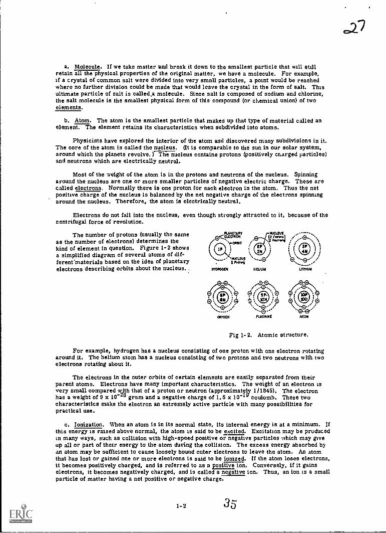
The number of protons (usually the sameas the number of electrons) determines thekind of element in question. Figure 1-2 showsa simplified diagram of several atoms of dif-ferent"materials based on the idea of planetaryelectrons describing orbits about the nucleus..
PLANETARY
) 11 k
\ j iHONOUR ROAM LIERIUIA
.0-CROiT i I
. g Promi
MIEN
Fig 1-2. Atomic structure.
For example, hydrogen has a nucleus consisting of one proton with one electron rotatingaround it. The helium atom has a nucleus consisting of two protons and two neutrons with twoelectrons rotating about it.
The electrons in the outer orbits of certain elements are easily separated from theirparent atoms. Electrons have many important characteristics. The weight of an electron isvery small compared with that of a proton or neutron (approximately 1/1845). The electronhas a weight of 9 x to-28 gram and a negative charge of 1.6 x 10⁻¹ coulomb. These twocharacteristics make the electron an extremely active particle with many possibilities forpractical use.
c. Ionization. When an atom is in its normal state, its internal energy is at a minimum. Ifthis energy is raised above normal, the atom is said to be excited. Excitation may be producedin many ways, such as collision with high-speed positive or negative particles which may giveup all or part of their energy to the atom during the collision. The excess energy absorbed byan atom may be sufficient to cause loosely bound outer electrons to leave the atom. An atomthat has lost or gained one or more electrons is said to be ionized. If the atom loses electrons,it becomes positively charged, and is referred to as a positive ion. Conversely, if it gainselectrons, it becomes negatively charged, and is called a negative ion. Thus, an ion is a smallparticle of matter having a net positive or negative charge.
1-2 35

1-3. CONDUCTORS AND INSULATORS
a. Conductors. Materials that allow free motion of a large number of electrons are called con-ductors. Electrical energy is transferred through conductors by means of the movement of free elec-
trons that move from atom to atom inside the conductor. Each electron moves to the neighboring
atom where it replaces one or more electrons by forcing them out of their orbits. The replaced
electrons repeat the process in other nearby atoms until the movement is transmitted through-
out the length of the conductor. A good conductor is said to have low opposition or low resistance
to current (electron) flow. Copper, silver, and aluminum are good conductors.
b. Insulators. Materials which require large amounts of energy to be expended In order to breakelectrons loose from the attraction of the nucleus are called insulators. Some such materials arerubber, glass, mica, and dry wood.
1-4. BASIC LAW
One of the basic laws of electricity is that like charges repel and unlike charges attract.Therefore, there is a force of attraction in the atom between the nucleus and the electrons re-
volving about it.
The word static means "standing atilt" or "at rest. " Static electricity was formerlyconsidered electricity at rest because the experimenters of long ago believed that electricalenergy produced by friction did not move.
A simple experiment can easily produce static discharges. If a ary non-metalliccomb is run vigorously through the hair several times and a cracking sound is heard, it indicates
static discharges are taking place. Charges are first built up on the hair and the comb by the
transfer of electrons from one to the ether caused by the friction between them. The discharge
is the rapid movement of electrons in the opposite direction from the comb to the hair as the
charges try to neutralize each other.
a. Charged bodies. In the aboie experiment strands of hair may stand out at angles becausethe loss of ele.ctrons has caused the hair to become positively charged and like charges repel
each other. Conversely, the comb has gained electrons and thus acquired a negative charge.
If the negatively charged comb is held near a piece of paper, the paper will be attracted to
it and will cling for a short time. The negative charge on the comb will repel free electrons on
the paper to the far side, leaving the side nearest the comb positively charged. Unlike charges
attract; therefore, the paper is drawn into contact with the comb. During this contact some of
the excess electrons move from the comb to the paper, giving the paper a negative charge.
Thus the paper is first attracted to the comb and then repelled by it.
In summary, a charged body is one that has more or less electrons than the normal number
of protons. It may be positively or negatively charged. A positively charged body has a deficiency
of electrons whereas a negatively charged body has an excess of electrons.
b. Coulomb's law of charges. As noted, charged bodies attract each other when they haveunlike charges and repel each other when they have like charges. The forces of attraction and
repulsion, stated in newtons, change with the magnitude of the charges and also with the distance
between them. This relation is stated in Coulomb's law of charges: charged bodies attract or repel
each other with a force that is directly proportional to the product of the charges on the bodies and
inversely proportional to the square of the distance between them,
The charge on one electron or proton might be used as the unit of electric charge, but itwould be impractical because of its very small magnitude. The practical unit of charge is the
coulomb.
1-3
3 6
1-5, ELECTRIC CURRENT
a. Free electrons. When an electron is removed from its orbit, It is referred to as a freeelectron. Some electrons of certain metallic atoms are so loosely bound to the nucleus that theyare comparatively free to move from atom to atom. Therefore, a very small force cr amount ofenergy will cause them to be removed from the atom and become free electrons. Such electronsmake up the flow of an electrical current in electrical conductors. The space between and aroundcharged bodies in which their influence is felt is called an electric field of force. The electricfield requires no physical or mechanical connecting link. It can exist in air, glass, paper, or avacuum. Electrostatic field and dielectric field are other names for this region of force.
Electric fields of force extend into the space surrounding their point of origin, and decreasein proportion to the square of the distance from their source. The electric field is related to thegravitational field that penetrates the space surrounding the earth, and acts through free space tocause all unsupported objects in that region to fall to the earth. Newton discovered the law ofgravity which states that every object attracts every other object with a force that is directly pro-portional to the product of the masses of the objects and inversely proportional to the square of thedistance between them.
Note the similarity between the law of gravity and the law of attraction of charged bodies.The gravitational fields hold the universe together, for with no gravitational field the planets wouldfly off into space rather than revolve around the sun. Similarly, electrons revolving around thepositive nucleus of the atom are held in their orbits by the force of attraction of the positive nucle-us. Thus, a field of force must exist between electrons and nucleus.
In diagrams, lines are used to represent the direction and intensity of the electric field offorce. The intensity of the field (field strength) is indicated by the number of lines per unit area(density), and the direction is indicated by arrowheads on the lines pointing in the direction inwhich a charge will move when,acted on by the field of force.
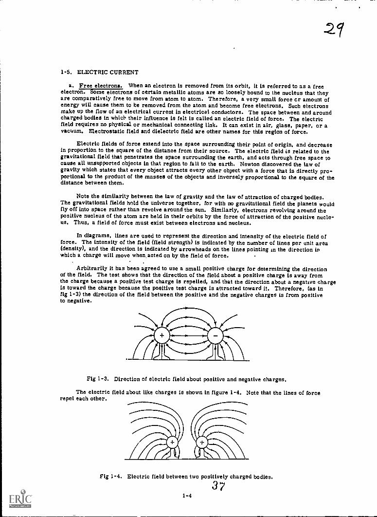
Arbitrarily it has been agreed to use a small positive charge for determining the directionof the field. The test shows that the direction of the field about a positive charge is away fromthe charge because a positive test charge is repelled, and that the direction about a negative chargeis toward the charge because the positive test charge is attracted toward it. Therefore, (as infig 1-3) the direction of the field between the positive and the negative charges is from positiveto negative.
Fig 1-3. Direction of electric field about positive and negative charges.
The electric field about like charges is shown in figure 1-4. Note that the lines of forcerepel each other.
Fig 1-4. Electric field between two positively charged bodies.
3 71-4

In both figures 1-3 and 1-4, the lines terminate on material objects and extend from apositive charge to a negative charge. They are regarded as imaginary lines in space alongwhich a real force acts. In both examples, the direction in which the force acts is that inwhich a positive test charge placed in the field will move, that is, from the positive chargeto the negative charge.
b. Current. The free electrons in a con- -77: SOURCE LOAD
ductor are moving constantly and changing posi-tions in a vibratory manner. If a source of supply(battery or d.c. generator) is connected tothe two ends of an electric circuit (fig1-5), the free electrons begin to move alongthe wires in one direction around the circuit.The direction of current flow is considered to be out from the negative terminal of the source,up through the load, and back to the positive terminal. The flow of electrons through the circuitis called an electric current. To determine the amount of current, the unit, ampere, has beenadopted. It is named after Andre Ampere who discovered the relation between the direction ofcurrent in a wire and the direction of the magnetic field around it. The symbol for ampere isI. A current flow of 1 ampere is equivalent to the flow of 6. 28 x 1018 electrons past a fixed point.
A o&anctard unit of electricity is moved through an electric circuit when 1 ampere ofcurrent flows for 1 second. This standard unit is equivalent to 6.28 x 10¹⁸ electrons. It iscalled the coulomb, and its symbol is Q. The rate of current flow in amperes and the quantityof electricity moved through a circuit are related by the common factor of time. Thus, thequantity of electric charge, in coulombs, moved through a circuit is equal to the product ofthe current in amperes, I, and the duration of current flow in seconds, t. Expressed as anequation, Q 2 It. For example, if a current of 2 amperes flows through a circuit for 10 seconds,the quantity of electricity moved through the circuit is 2 x 10 = 20 coulombs.
Fig 1-5. Current (electron) flow in a circuit.
1-6. ELECTROMOTIVE FORCE
a. Force. The force that causes free electrons to move in a conductor as an electric currentis called electromotive force, voltage, or difference in potential. When a difference in potentialexists between two charged bodies connected by a conductor, electrons will flow along theconductor from the negatively charged body to the positively charged body until the two chargesare equalized and the potential difference no longer exists. An example of this action is shownin the two water tanks connected by a pipe and valve in figure 1-6. At first the valve is closedand all the water is in tank A. Thus, the water pressure across the valve is maximum. Whenthe valve is opened, water flows through the pipe from A to B until the water level becomes thesame in both tanks. Then the water stops flowing because there is no longer a difference inwater pressure between the two tanks.
b. Current flow, Current flow through an electric circuit is directly proportional to the dif-ference in potential across the cimuit, just as the flow of water through the pipe in figure 1-6 isdirectly proportional to the difference in water level in the two tanks.
Fig 1-6. Water example of difference in potential.
1-5
38
3e

3 /
The usual means of obtaining a voltage are batteries and generators. The unit of electricpressure is the volt, named after Alessandro Volta, who invented the first electric battery.
Note: A fundamental law of electricity is that the current is directly proportional to theapplied voltage.
1-7. RESISTANCE
a. Definition. Electrical resistance is that quality of a substance that opposes currentflow through it. The simple electric circuit of figure 1-5 has resistance to a varying degree inall parts of it, that is, in the source, in the load, and in the connecting wires. The size and ma-terial of the wires are such as to keep the resistance low so that current can flow as easily throughthem as water flows through the pipe between the tanks in figure 1-6 when the valve is opened. Ifthe water pressure remains constant, the flow of water will vary with the opening of the valve.The smaller the opening, the greater the opposition to the flow, and the smaller the rate of flow.
In an electric circuit, the larger the diameter of the wires the lower will be their electricalresistance to the current llow through them. In the water example, pipe friction opposes the flowof the water between the tanks. The resistance of the pipe depends on its length, diameter, andthe nature of its inside walls. Similarly, the electrical resistance of conductors depends on thelength, diameter, and material of the wires. The symbol for resistance is R, and it is measuredin ohms.
b. Temperature. Temperature also affects resistance. In most conductors (copper, alu-minum, iron, etc.) resistance increases with temperature. Carbon is an exception. Its resistancedecreases with an increase in temperature.
1-8. MAGNETS
a. Substance. A substance is said to be a magnet If it has the property of magnetism, that is,the ability to attract such substances as iron, steel, nickel, or cobalt, which are known as mag-netic materials. A magnet exhibits two points of maximum attraction (one at each end or "mag-netic pole"), but no attraction at its center. If a magnetized needle is suspended so that it ro-tates freely in a horizontal plane about its center, it will come to rest in approximately a north-south line of direction, with the Immo pole always pointing north. The magnetic pole that pointsnorth is called the north pole and the other, the south pole.
A magnetic field exists around a simplebar magnet. The field consists of imaginarylines along which a magnetic force acts. Theselines flow from the north pole of the magnetand enter the south pole, returning to thenorth pole through the magnet itself, thusforming closed loops as shown in figure 1-7.
Fig 1-7. Lines of force in a bar magnet.
b. Groups of magnets. Magnets may be divided into three groups: (1) natural magnets, foundIn a natural state in the form of a mineral called magnetite; (2) permanent magnets, bars of hard-ened steel or soma form of alloy (such as alnico) that have been permanently magnetized; and(3) electromagnets, composed of soft-iron cores around which coils of insulated wire are wound(fig 1-8, )
1-6 39

3;1-
NATURAL PERMANENT ELECROMAGNET
Fig 1-8. Three types of magnets.
1-9, NATURE OF MAGNETISM
Weber's theory of the nature of magnetism is based on the assumption that each of themolecules within a magnet is in itself a tiny magnet. The molecular magnets that make upan unmagnetized bar of iron or steel are arranged at random (fig 1-9A). In this arrangement,the magnetism of each of the molecules is neutralized by that of adjacent molecules, and noexternal magnetic effect is prochtzed. When a magnetizing force is applied to an iron or steelbar, the molecules become alined so that the north poles point in one direction and the southpoles pointin the opposite direction (fig 1-9B).
OP '4 CIIISOc5r11/&_Cli4:1114, tzlrus
Ctie
El 111:1 11C1 El 11C IADWI MD MO ID 110 111:3 ICJSC MD NO MC 111:3 El MCIICI IC 11E3 WI El VC1 IMO
UNMAGNETIZED STEEL MAGNETIZED STEEL(B)(A)
Fig 1-9. Molecular theory of magnetism.
If a bar magnet is broken into several parts (as in fig 1-10), each part constitutes acomplete magnet. The north and south poles of these smaller magnets are in the samerespective positions as in the original bar magnet. If this breaking process is repeated,smaller and smaller pieces would retain their magnetism until each was reduced to amolecule. Therefore, it is logical to assume that each of these molecules is in itself amagnet.
.111111111111111111n" '114111111111111111:
:V*4 \P.4
-..t V1.
'nunimitinimr:. Ntiuminuninumnu6..ilmmuntha
Fig 1-10. Magnetic poles in a broken magnet.
a. Magnetic fields and lines cf force. As mentioned (para 1-8), the ends of the magnetwhere the attractive force is the greatest are called the poles. By using a compass, the lineof direction of the magnetic force at various points near the magnet may be observed. Thecompass needle itself is a magnet. The "N" end of the compass needle always points towardthe south pole (S, in fig 1-11), and thus a sense of direction is also indicated. At the center,the compass needle points in a direction that is parallel to the bar magnet.
When the compass is placed successively at several points near the bar magnet, thecompass needle alines itself with the field at each position. The direction of the field is indicatedby arrows, and represents the direction in which the north pole of the compass needle will point
1-7
40

7111111131.51,11111MMINNIM,WIRIONIEMMIONAMM7100111111111311t ,
when placed in this field. A line along which a compass needle alines itself is called a magneticline of force. As mentioned previeuely, the magnetic lines of force are assumed to flow fromthe north pole, pas through space, and enter the south pole. Then they pass from the southpole to the north pole inside the magnet to form a closed loop. Each line of force forms anindependent closed loop, and does not merge with or cross other lines of force.
L.GIC=7,
*%.
Fig 1-1I. Magnetic lines of force.
The space surrounding a magnet, in which the msgnetic force acts, is called a magneticfield. Michael Faraday was the first scientist to visualize the magnetic.field as being in astate of stress and consisting of uniformly distributed lines of force. The entire quantity ofmagnetic lines surrounding a magnet is called magnetic flux. Flux in a magnet correspondsto current in an electric circuit.
The number of lines of force per unit area is called flux density, and is measured in ltnesper square inch or per square centimeter. Flux density is expressed by the equation 3 -
is the flux density, 4) (Greek phi) is the total number of lines of flux, and A is the cross-sectional area of the magnetic circuit.
A visual representation of the magneticfield of a magnet can be obtained by placinga plate of glass over a magnet and sprinklingiron filings onto the glass. The filings ar-range themselves in a pattern of definite pathsbetween the poles (fig 1-12).
Z1/4 ,Ntur,-No\k.%
.1.
or%
4411\44`;
Fig 1-12. Magnetic field around a bar magnet.
b. Laws of attraction and repulsion. If a magnetized needle is suspended near a bar magnetas in figure 1-13, it will be seen that a north pole repels a north pole and a south pole repelsa south pole. However, opposite poles will attract each other. Thus, the first two laws ofmagnetic attraction and repulsion are: Like magnetic poles repel each other. Unlike polesattract.
4
1-8
33

REPULSION REPULSION ATTRACTION
Fig 1-13. Laws of attraction and repulsion.
The flux patterns between adjacent unlike poles of bar magnets, as indicated by lines,are shown in figure 1-14A. Similar patterns for adjacent like poles are shown in figure1-1413. The lines do not cross each other at any point, and they act as if they repel each other.
". :::::::::::::::::::::::::: ::::: .....:- ...;,,. ,. ........ ........... O.. . .. ..0
O.... CI .................
(r..
..... ........ ... .... 0. .....
....... 1. : ....
.1. I t ( .0 ..... .. ......1Al it ..... ..... ) .. :1....c..fIr:::.
.....1 .1 i t fel....................... . .....
. :Z :.;:i. 7 .4. .:. % ....,.... .411'2 ..ei:::!;,.....:i.I.V§ 4.. 711:e: fd: :
......:0:7; . OW.54.11.?. ../.:;" .9..A?::;:,':.... r........y... t1/01.0.:;.... ,v,_e,3,.. .1 ) N.:17.N.
(S...(..,::: 7::(...::.......--:.;.F:. . ...i..1); it.t.t..:.r... .71......:......../
. --.:-... ..... -- ........ . ... . ,..,........::::==........ k:.. .. -1 ........
, . - ................. .... ........ ....... ...... ................. ::,....7.'.., ' *.
..... UNES OF FORCE. ,UNLIKE POLES ATTRACT
A
LIKE POLES REPEL
Fig 1-14. Lines of force between unlike and like poles.
Figure 1-15 shows the flux pattern around two bar magnets placed close together andparallel with each other. Figure 1-15A shows the flux pattern when opposite poles are ad-jacent, and figure 1-15B1the pattern when like poles are adjacent.
FLUX PATTERN-ATTRACTION
A
FLUX PATTERN-REPULSION
Fig 1-15. Flux patterns of adjacent bar magnets.
1-9
42
35/

35"
The third law states that the force of attraction or repulsion varies directly as theproduct of the separate pole strengths, and inversely as the square of the distance separatingthe magnetic poles. For example, if the distance between two north poles is increased from2 feet to 4 feet, the force of.repulsion between them is decreased to one-fourth of its originalvalue. If either pole strength is doubled and the distance remains the same, the force betweenthe poles will be doubled.
I -10. SYMBOLS
The following are some symbols used in this course:
Symbol Meaning
.=.. d.c. power source; battery
0 a. c. power source; generator
resistor; resistance is stated with the letter R
IMP- coil; inductance is stated with the letter L
--I P.--- capacitor; capacitance is stated with the letter C
1 - 10
43
_
3 0Chapter 2
ANTENNA AND TRANSMISSION LINE FUNDAMENTALS
2-1, ELECTROMAGNETIC FIELD
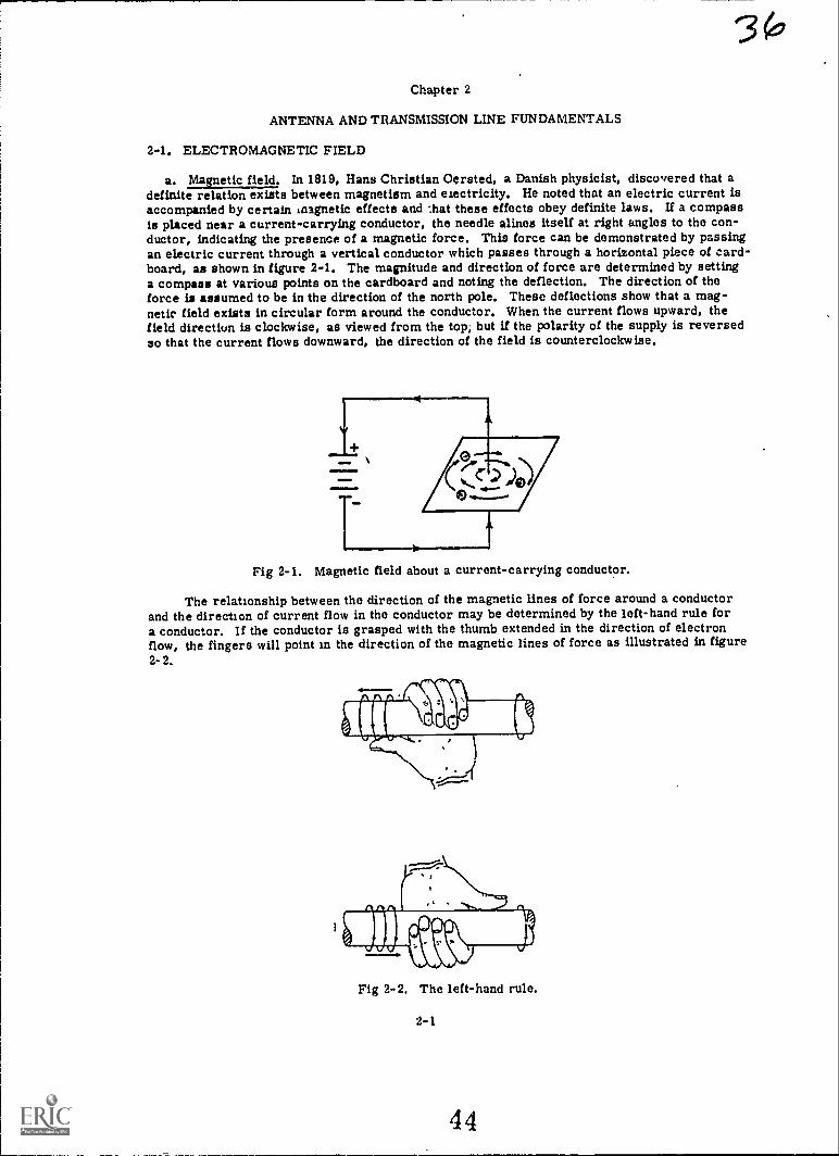
a. .1taimelielci. In 1819, Hans Christian Oersted, a Danish physicist, discovered that adefinite relation exists between magnetism and electricity. He noted that an electric current isaccompanied by certain inagnetic effects and :hat these effects obey definite laws. If a compassis placed near a current-carrying conductor, the needle alines itself at right angles to the con-ductor, indicating the presence of a magnetic force. This force can be demonstrated by passingan electric current through a vertical conductor which passes through a horizontal piece of card-board, as shown in figure 2-1. The magnitude and direction of force are determined by settinga compass at various points on the cardboard and noting the deflection. The direction of theforce is assumed to be in the direction of the north pole. These deflections show that a mag-netic field exists in circular form around the conductor. When the current flows upward, thefield directiun is clockwise, as viewed from the top; but if the polarity of the supply is reversedso that the current flows downward, the direction of the field is counterclockwise.
Fig 2-1. Magnetic field about a current-carrying conductor.
The relationship between the direction of the magnetic lines of force around a conductorand the direction of current flow in the conductor may be determined by the left-hand rule fora conductor. If the conductor is grasped with the thumb extended in the direction of electronflow, the fingers will point in the direction of the magnetic lines of force as illustrated in figure2-2.
Fig 2-2. The left-hand rule.
2-1
44

b. Magnetic field strength. Figure 2-3 illustrates what happens to the strength of the magneticor "H" field as the current flow through the conductor is varied and the distance of the meter fromthe conductor is held constant.
A B C
Fig 2-3. Effects on the "H" field as current through the conductor is varied.
Vath a current of 5 amperes flowing in the conductor and the meter placed 1 inch from theconductor, we have a meter reading of 5, as shown in figure 2-3A. If the current flow is de-creased to 2.5 amperes (fig 2-3B), the meter also decreases to 2.5. In figure 2-3C, as thecurrent is increased to 7.5 amperes, the meter reading also increases to 7.5. Thus, thestrength of the "H" field is directly proportional to the current flow through the conductor.
As the point of measurement is varied, a different effect takes place. In figure 2-4A,we begin with the original condition of 5 amperes through the conductor and the meter placed1 inch from the conductor. The meter reading is 5. As shown in figure 2-4B, the current isheld constant at 5 amperes and the distance is increased to 2 inches. The meter reading de-creases to 1.25. The distance has been doubled, but the meter reading has decreased to one-fourth of its original value. If we increase the distance to 3 inches, the meter reading is now0.55. The dthtance has been tripled, but the meter reading has decreased to one-ninth itsoriginal value. Thus, the strength of the "H" field varies inversely with the square of thedistance from the conductor.
H LINESM°2--'2" f°..
A 3 C
Fig 2-4. Effects on the "H" field as the distance from the conductor is varied.
452-2
37

c. Electric field, Surrounding every electrically charged body is a field of force. When abody tiereCIFGETcharged, there is a greater or lesser concentration of electrons than normal.Thus, a difference in potential exists. An electric field is therefore associated with a differencein potential.
With the use of two conductors in our circuit of figure 2-5A, we have a form of capacitor.A capacitor is any two conductors which are separated by a dielectric. Thus, with our two con-ductors and the air between them serving as the dielectric, we have a capacitor.
ELECTRICFIELDLINES
A
_
DIFFERENCE LN POTENTIAL
B
Fig 2-5. Electric field between capacitor plates.
Since the top wire in figure 2-5A has a negative polarity in respect to the bottom wire, adifference in potential exists. An electric field is associated with this difference in potential.
In figure 2-5B, the capacitor is charged and the source voltage removed. The capacitorremains in its charged state. Thus, electric lines of force exist between the two conductors.
In figure 2-6, if we gradually open the two conductors until they are vertical, the electricfield now covers a greater area.
d. Electric field strength. In measuring the strength of the electric or "E" field, we willnotice that a different action takes place as compared with measuring the magnetic field strengthas the distance is varied.
"E" LINES
B .i. C 1-
Fig 2-6. Open electric field.
2-3
4 6
3 7
3q
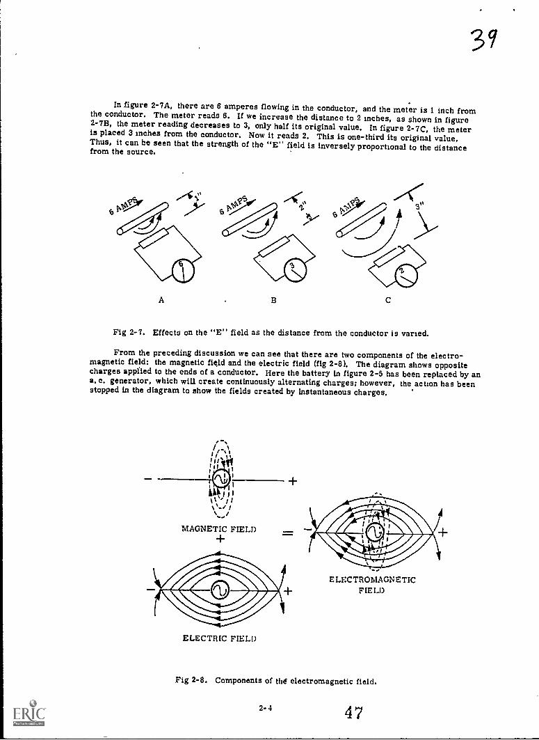
In figure 2-7A, there are 6 amperes flowing in the conductor, and the meter is 1 inch fromthe conductor. The meter reads 6. If we increase the distance to 2 inches, as shown in figure2-78, the meter reading decreases to 3, only half its original value. In figure 2-7C, the meteris placed 3 inches from the conductor. Now it reads 2. This is one-third its original value.Thus, it can be seen that the strength of the "E" field is inversely proportional to the distancefrom the source.
A B C
Fig 2-7. Effects on the "E" field as the distance from the conductor is varied.
From the preceding discussion we can see that there are two components of the electro-magnetic field: the magnetic field and the electric field (fig 2-8). The diagram shows oppositecharges appfted to the ends of a conductor. Here the battery in figure 2-5 has been replaced by ana. c. generator, which will create continuously alternating charges; however, the action has beenstopped in the diagram to show the fields created by instantaneous charges.
S./
MAGNETIC FIELD+
+
ELECTRIC FIELD
ELECTROMAGNETICNEU)
Fig 2-8. Components of Old electromagnetic field.
2-4
1
47
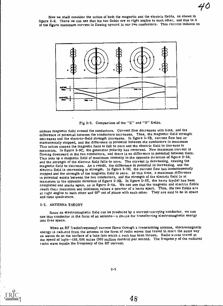
Now we shall consider the action of both the magnetic and the electric fields, as shown infigure 2-9. There we can see that the two fields are at right angles to each other, and that in Aof the figure maximum current is flowing upward in our two conductors. This current induces an
Fig 2-9. Comparison of the "E" and "H" fields.
intense magnetic field around the conductors. Current flow decreases with time, and thedifference in potential between the conductors increases. Thus, the magnetic-field strengthdecreases and the electric-field strength increases. In figure 2-9B, current flow has in-stantaneously stopped, and the difference in potential between the conductors is maximumThis action causes the magnetic field to fall to zero and the electric field to increase tomaximum. In figure 2-9C, the generator polarity has reversed. Now maximum current isflowing downward in the two conductors, and there is no difference in potential between them.This sets up a magnetic field of maximum intensity in the opposite direction of figure 2-9A,and the strength of the electric field falls to zero. The current is decreasing, causing themagnetic field to decrease. As a result, the difference in potential is increasing, and theelectric field is increasing in strength. In figure 2-9D, the current flow has instantaneouslystopped and the strength of the magnetic field is zero. At this time, a maximum differencein potential exists between the two conductors, and the strength of the electric field is atmaximum in the opposite direction of figure 2-9B. In figure 2-9E, the hertz (cycle) has beencompleted and starts again, as in figure 2-9A. We can see that the magnetic and electric fieldsreach their maximum and minimum values a quarter of a hertz apart. Thus, the two fields areat right angles to each other and 900 out of phase with each other. They are said to be in spaceand time quadrature.
2-2. ANTENNA THEORY
Since an electromagnetic field can be produced by a current-carrying conductor, we canuse this conductor in the form of an antenna--a device for transferring electromagnetic energyinto free space.
When an RF (radiofrequency) current flows through a transmitting antenna, electromagneticenergy is radisted from the antenna in the form of radio waves that travel in much the same wayas waves do on the surface of a lake into which a rock has been thrown. Radio waves travel atthe speed of light--186,000 miles (300 million meters) per second. The frequency of the radiatedradio wave equals the frequency of the RF current.
2-5
4 8
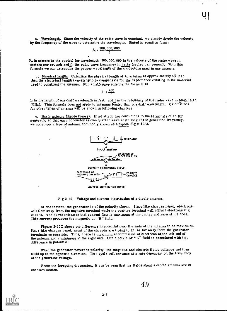
a. Wavelength. Since the velocity of the radio wave is constant, we simply divide the velocityby the frequency of the wave to determine the wavelength. Stated in equation form:
,300 000, 000f
7%. in meters is the symbol for wavelength; 300,000,000 is the velocity of the radio wave inmeters per second; and f, the radio wave frequency in hertz (cycles per second). With thisformula we can determine the proper wavelength of the conductors used in our antenna.
b. Physical length. Calculate the physical length of an antenna at approximately 5% lesethan the electrical length (wavelength) to compensate for the capacitance existing in the materialused to construct the antenna. For a halt-wave antenna the formula is
468L = -rL is the length of one-half wavelength in feet, and f is the frequency of the radio wave in Megahertz(MHz). This formula does not apply to antennas longer than one-half wavelength. Calculationsfor other types of antenna will be shown in following chapters.
c. Basic antenna (dipole theoly). If we attach two conductors to the terminals of an RFgenerator so that each conductor is one-quarter wavelength long at the generator frequency,we construct a type of antenna commonly known as a dipole (fig 2-10A).
ADIPOLE ANTENNA
el.
GENERATOR
DIRECTION OF..,<ELECTRON FLOW
.11..
IICURRENT DISTRIBUTION CURVE
ELECTRONS ORNEGATIVE CHARGES
POSITIVECHARGES
C
VOLTAGE DISTRIBUTION CuRVE
Fig 2-10. Voltage and current distribution of a dipole antenna.
At one instant, the generator is of the polarity shown. Since like charges repel, electronswill flow away from the negative terminal while the positive terminal will attract electrons. (fig2-10B). The curve indicates that current flow is maximum at the center and zero at the ends.This current produces the magnetic or "H" field.
Figure 2-10C shows the difference in potential near the ends of the antenna to be maximum.Since like charges repel, most of the charges are trying to get as far away from the generatorterminals as possible. Thus, there is maximum accumulation of electrons at the left end ofthe antenna and a minimum at the right end. Our electric or "E" field is associated with thisdifference in potential.
When the generator reverses polarity, the magnetic and electric fields collapse and thenbuild up in the opposite direction. This cycle will continue at a rate dependent on the frequencyof the generator voltage.
From the foregoing discussion, it can be seen that the fields about a dipole antenna are inconstant motion.
4 9
2-6
q I

2-3. RADIATION
a. Basic theory. The exact manner in which the electrical energy leaves the antenna is ahighly complex operation. The complete explanation would involve the use of advanced mathe-matics, whicb is beyond the scope of this manual. Our coverage is limited to a description ofthe manner in which energy loops are formed, and the path they travel upon leaving the antenna.
(1) Consider the electric field as previously discussed. It is at highest intensity whenmaximum difference in potential exists between the ends of the antenna (fig 2-11A).As the output of the RF generator decreases, the charges built up at the ends of theautenna move toward the center and the "E" field begins to decrease in intensify(fig 2-11B). The collapsing "E" field causes the "E" lines near the ends of theantenna to move along the surface of the conductor toward the center. Since "E"lines repel other "E" lines, the center of the field is forced outward. Finally, therepulsion effect is great enough that the "E" lines form an energy loop and brditkaw.ay from the conductor (fig 2-11C). When the RF generator rev!rses polarity,"E" lines begin to build up in the opposite direction (fig 2-11D). T`lis new "E"field causes the energy loop that has broken free to be repelled still farther intospace (fig 2-11E).
A
1) E
Fig 2-11. Development of radiation.
2-7
50

(2) This action can be understood more easily by comparing it to what takes place when anobject is continuously dropped on the surface of a lake. The same type of action takesplace at the antenna, except that water takes the place of free space and the electricfield is replaced by the object. Figure 2-12A illustrates an object about to strike thewater's surface. Figure 2-12B shows the wave being formed as the object strikes thewater. In figure 2-12C, the object has sunk below the water's surface and the watercloses over it. The initial velocity of the object forces the wave to move radiallyoutward. Figure 2-12D shows the leading wave continuing to move outward with thefollowing waves gradually decreasing in amplitude.
'ALONG OILACT
ACAPPAG WAMC rOAM$ AT WPM.°0111JECT 31AKCY *An,
1$.....,LCAINAC WWI M0VC5 AACAALV CA4AMAC
Fig 2-12. Wave motion on the water's surface.
Of course, figure 2-12 does not dupli-cate the action of radiation; but if wewere to tie a string to the object wecould produce continuous wave motion,as shown in figure 2-13. If the objectwere pulled sharply upward after itsinitial fall (fig 2-13A), and droppedagain, continuous wave motion couldbe produced (fig 2-13B). The upwardand downward motion of the object con-tinually striking the water's surfacewould keep reinforcing the decreasingamplitude of the succeeding waves.
Fig 2-13. Formation of continuous waveson the water's surface.
(3) In (2) above, the magnetic field was ignored. By the same reasoning, magnetic lines offorce may become detached from the antenna and resultant energy loops repelled intospace.
As the RF generator alternately changes polarity, a continuous beam of energy inthe form of electric and magnetic lines of force will be repelled away from the antenna.
2-8 51

The two will combine, forming a radiated electromagnetic field. (Note that no field isradiatqd from the ends of the antenna.) As the field advances, the energy becomesspread out over a greater area. The shape of this area or pattern is determined bythe type of antenna used.
b. Basic patterns. Since the antenna ia usually designed to have a specific pattern for usewith a particular installation, it is desirable to put the radiation pattern on paper where it canbe examined. The radiation pattern is a measurement of the energy radiated from an antenna,taken at various angles and at a constant distance from the antenna.
(1) Isotropic radiation. A source of radiant energy, such as the sun, radiates light equallyin all directions. A radiator of this type is known as an isotropic, source of radiation.This simply means that the energy coming from the source is found to be constant at afixed distance,from whatever angle it is measured. Assume that a measuring deviceis moved in a circle around the sun. At any point along the circle, the distance fromthe measuring device to the sun is the same; and the measured radiation remains thesame.
If measured radiation is plotted against various positions taken along the circlearound the sun, the result is the graph in figure 2-14. Assume that the radiation ismeasured on a scale of 0 to 10 units, and that the radiation measured is shown to be7 units at each position. The graph of the measured radiation, therefore, is a straightline plotted against positions along the circle. The graph of measured radiation justdescribed is a form of radiation pattern. The straight line represents the radiationpattern of an isotropic source taken in the plane of the measuring circle.
2................ -....... ,.. ... 10 -. I
1
I/
-.,...
.\\ [ I 1/,,,
...,
1
1
1
zo s -
I 1
s -v. 9 -
/
4 t + 01
.... .15 -
I. /% I/ I I / 0w 3 -\ / t\ / C -\ / n
..c% af
W1 -
..
ow 4.
ALL POSITIONS ARE EQUALDISTANCES FROM THE SUN.
1 2 3 4 3 6 7
POSITION ON CIRCLE
Fig 2-14. Isotropic radiation.
(2) Amsotropic radiation. It is possible to 4.ve a radiator which emits strc,nger radiationin one direction than in another. Such sources are called anisotropic. 1n example,shown in figure 2-15, is the ordinary flashlight. The beam illuminates only a portion ofthe total space surrounding the flashlight. If a circle is drawn having the light source ascenter, the radiation can be measured at different positions along the circle. Eachposition used for measurement is the same distance from the light source. In otherwords, conditions are exactly those used in measuring the light radiated from theisotropic source.
At position 0 on the circle, which is directly behind the light source, the radiationmeasured is negligible. A zero value accordingly is assigned to this position on thegraph at the right. Until position 4 is reached, the radiation remains negligible. Be-tween 4 and 6, the circle passes from comparative darkness into the flashlight beam.This is an area of sharp transition from darkness to brightness, as can be observedeasily on the graph. Radiation is relatively constant moving from positions 6 to 10,
2-9
52

reaching a maximum at position 8, which is directly in the path of the beam. Between10 and 12, the measured radiation falls off sharply, becoming and remaining negligiblefrom 13 to 16.
Radiation from a light source and radiation from an antenna are both in the formof electromagnetic waves: The measurement of radiation from an antenna, therefore,follows the same basic procedures as the one just described for the sun and the flash-light. These measurements can be graphed to obtain a radiation pattern for the antenna.
214. GRAPHS
Before proceeding with the study of antenna patterns, it is necessary to consider in detailmethods used to graph measured values of radiatior.,
10
43
1
0 1 2 34 5117 111110111301454
POSMON ON CIRCLE
Fig 2-15. Anisotropic radiation.
a. Rectangular-coordinate graph. Figures 2-14 and 2-15 show the rectangular-coordinatetype of graph used to plot the measured value of radiation against the position at which themeasurement is taken. Ths numbered positions along the circle are laid out along the horizontalaxis of the graph from 0 to 7. The units of measured radiation are laid out along the verticalaxis from 0 to 10. Units on both axes usually are chosen so that the pattern occupies a con-venient area of the graph.
The horizontal and vertical axes are at right angles to each other. The point at which theaxes cross each other is called the origin. In this case, the origin has the value of zero on bothaxes. Now, assume that a radiation value of 7 units is measured at position 2., From position2 on the horizontal axis, a line (vertical dashes) is projected running parallel to the vertical axis.From 7 on the vertical scale, a line (horizontal dashes) is projected running parallel to the hori-zontal axis. The point at which the two lines intersect represents the value of 7 radiation unitsat position 2. Note that this is the only point on the graph that can represent this value.
The vertical and horizontal axes plus the two dashed lines used to plot the point enclose anarea forming a rectangular-shaped area. Therefore this type of graph is called rectangular co-ordinate. A new rectangle is formed for each different point plotted. In figure 2.14, all thepoints plotted lie along a straight line extending from 7 units on the vertical scale to the projectionof position 7 on the horizontal scale. Thus the straight line is the characteristic pattern in rectan-gular coordinates of an isotropic source of radiation.
b. Polar-coordinate graph. Although the rectangular-coordinate method of graphical analysisis used widely, another method has proved to be more practical in studying radiation patterns.the polar-coordinate type of graphical analysis (B, fig 2-16). For convenience, the graph offigure 2-14 is reproduced in A of figure 2-16. Note the great difference in shape of the radiationpattern when it is transferred from the rectangular coordinate to the polar-coordinate graph. Thescale of values used in both graphs is identical, and the measurements taken are both the same.The basic difference, which results in the difference in physical appearance, is in the type ofaxes used.
In the rectangular-coordinate graph, points are located!), means of projections from apair of axes at right angles to each other. These axes remain stationary at all times. In thepolar-coordinate graph, one axis consists of concentric circles, and the other axis consists ofa rotating radius extending from the center of the concentric circles. Recall how radiation was
532-10
45-

A/6.measured by traveling in a circle around the sun. Assume a radius, R, drawn from the sun ascenter to position 0 on the circle. Moving to position 1, the radius moves to position 1; movingto position 2, the radius also moves to position 2; and so on. This moving radius constitutesthe moving axis of the polar-coordinate graph.
The positions of the radius are marked on the polar-coordinate graph for each position atwhich a measurement is taken. Note how the radius indicates the actual direction from which themeasurement was taken. This is a distinct advantage over the rectangular-coordinate system,in which the position is indicated along a straightline axis having no physical relation to the positionon the circle. Having established the direction in which the measurement was taken by means ofthe rotating axis, it remains to devise means for indicating the measured radiation.
The rotating axis passes from the center of the graph to some position marked on the edgeof the graph. In so doing, it intersects a set of concentric circles spaced at equal distances fromeach other. Going out from the center, the circles get larger and larger. These circles are usedto indicate the measured radiation. They are numbered successively from the center outward, thecenter indicating a zero measurement. In the graph in B of figure 2-16, a radiation scale goingfrom 0 to 10 units is used. Consequently, 10 concentric circles go from the center to the circum-ference of the graph. These circles are marked 1, 2, 3, and so on, with 10 designating the largestcircle. This scale corresponds to the scale marked on th, vertical axis of the rectangular-coordinategraph in A, figure 2-16.
In brief, the rotating radius of the polar-coordinate graph serves the same purpose as thestationary horizontal axis of the rectangular-coordinate graph. It has the advantage of indicatingthe actual direction from which the measurement is taken. The concentric circles serve the samepurpose as the vertical scale on the rectangular-coordinate graph. They allow the same scale tobe used no matter what the position of the rotating radius. The distance from the source is constantfor both types of graphs.
At position 0 in B, figure 2-16, the radius extends from the center outward to the right. Theradiation measured is 7 units in this position. This point is recorded by going out seven circlesalong the radius. The point is the place where the radiu..% intersects the seventh circle. Recordingof the radiation measured in position 1 follows the same procedure. Since the source is isotropic,the measured radiation again is 7 units. The radius is rotated to position 1, and its intersectionwith the seventh circle is marked.
When all points are recorded through position 7, they all lie on the seventh concentric circle.Therefore, the radiation pattern of the isotropic source is a circle. This contrasts sharply withthe straight-line pattern obtained with a rectangular-coordinate-type graph. The advantages of thepolar-coordinate graph are evident immediately. The source, which is at the center of the obser-vation circle, is at the center of the gra. Also, the direction taken by the radiated energy canbe seen directly from the graph. For these reasons, the polar-coordinate graph is more useinlin plotting radiation patterns.
NOTE:THE SOURCE OF nAoymomMTN! SAME FOR ROTH AARO 8
A
Fig 2-16. Comparison of rectangular- and polar-coordinate graphs for an isotropic source.
2-11
54

In figure 2-15 the radiation pattern of the common flashlight is graphed in rectangularcoordinates. This graph is reproduced for convenience in A of figure 2-17. From the physicalpicture of the flashlight beam, it is evident that the light source is anisotropic in nature. This isnot evident in the radiation pattern traced on the rectangular-coordinate graph. Conversely, theradiation pattern of the flashlight phown in B of figure 2-17 bears some physical resemblance tothe actual beam. This is the same pattern, drawn with polar coordinates.
The positions on the circle marked off on the two polar-coordinate graphs given have beenselected and numbered arbitrarily. It is possible to mark off positions around the circle in astandard way so that one radiation pattern can be compared easily wit:, nother. The standardmethod is based on the fact that a circle is divided into 3600. The radius extending from thecenter horizontally to the right (position 0 in B of fig 2-17) is designated 0°. Advancing toposition 4 rotates the radius until it is at right angles to the 00 radius. This radius positionaccordingly is marked 900. Therefore, position 8 is 180°, position 12 is 270°, and position16 is 3600, by the same reasoning. The various radii drawn on the graph are marked accordingto the angle each radius makes with the reference radius at 00.
In B of figure 2-17, the polar-coordinate graph shows a definite area enclosed by theradiation pattern, indicating :fib general direction of radiation from the source. This area iscalled a lobe. Outside of this area, no radiation is emitted in any direction. For example, atan angle of 45° (position 2), the radiation is zero. Such a point is called a null. Practicallyspeaking, there is usually some radiation in every direction. A null, therefore, also is usedto indicate directions of minimum radiation. In the pattern given, there is one lobe and onecontinuous null.
O 4
4
MAMMUM RADIATION
II 2 3 4 5 6 7 8 IOIII3,4I$
A
Fig 2-17. Comparison of rectangular- and polar-coordinate graphs for anisotropic source.
2-5. POLARIZATION
a. Radiated wave. Since the dipole antenna is a source of radiation, its radiation patterncan be measured. Figure 2-18 is a 3-dimensional view of this radiation pattern. It resemblesthe shape of a doughnut.
55
2-12
97

9fHONiZONTAL
PLANEPATTERN
ANTENNAAXtS
AKTOINA
Lose
VERTICALPLANE
PATTERN
NULLIse"#V255. .35.
441,4*WW1**44145.
NULSOLID PATTERN
Fig 2-18. Radiation pattern of a dipole antenna.
315
-o LOBE
From this view, two types of patterns can be drawn. The first view is obtained by cutting atop view through the center of the doughnut in a horizontal plane. The antenna becomes simplya dot in a large circle. Note that the radiation is constant in any direction along the horizontalplane.
A vertical plane pattPrn can be obtained by slicing the doughnut in half down through thecenter of the antenna. This pattern exhibits two lobes and two nulls. The reason for this figure-eight pattern is that no energy is radiated from the ends of the antenna.
The antenna shown is mounted vertically. Should it be mounted horizontally, the radiationpattern shown in figure 2-18 would be reversed. This means that an antenna could be eitherhorizontally or vertically polarized.
b. "E" field. Polarization of a radiated wave is determined by the direction of the linesof force in the "E" field. The wave is said to be vertically polarized when the lines areperpendicular to the earth's surface. If the lines of force of the "E" field are parallel to theearth's surface, the wave is said to be horizontally polarized.
When an electromagnetic field is radiated from an antenna, the "E" field is built upfrom one end of the antenna to the other. Therefore, the lines of force of the "E" field arealways parallel to the position of the antenna. Simply stated, a vertically positioned antennaproduces a vertically polarized wave, and a horizontally positioned antenna produces ahorizontally polarized wave.
2-13
5 6

2-6. ANTENNA INPUT IMPEDANCE
a. Input. The input impedance of the antennais defined as the impedance "seenn,by thetransmitter at the input terminals of the antenna.
b. Impedance. Since different conditions ofcurrent and voltage exist at different points alongthe half-wave antenna, the impedance at thesepoints must vary. If the voltage is divided by thecurrent at each point, an impedance curve forthe antenna can be developed, as shown in figure2-19. It is calculated to be approximately 73ohms at the center and 2,500 ohms at the ends.
2........
'X./2
2500OHMS
(ENO)
73OHMS
(dENTER)
qf
Fig 2-19. Impedance curve for a half-waveantenna.
This impedance is made up of resistance and reaztance. If the antenna is cut exactly tolength, the reactance is zero. U the antenna is made shorter, capacitive reactance is present.Conversely, when the antenna is made longer, inductive reactance is present. These reacttvecomponents are undesirable since they reduce the amount of power radiated from the antenna.
Note; The input impedance of the antenna is of extreme importance since it determines thetype of transmission line used to couple it to the transmitter.
2-7. TRANSMISSION LINE THEORY
a. Properties. A transmission line is a device for transferring electrical energy from opelocation to another. It is used to couple energy from the transmitter to the antenna. At timesthe transmitter can be connected directly to the antenna, but generally the antenna is located somedistance away, and a transmission line must be used as a connecting link. Its function is totransfer the power output of the transmitter to the antenna with minimum loss. How well thelosses are kept down depends on the characteristics of the transmission line used.
A transmission-line has the properties of inductance (L), capacitance (C), and resistance(R), just as in any conventional electronic circuit. Me only difference is that these propertiesare generally components in conventional circuits. Figure 2-20 illustrates a transmission line(A) and its equivalent circuit (B).
57
2 -14

TRANSMITTERINPUTENO
TRANSMISSIONLINE
OUTPUT
ENOANTENNA
Fig 2-20. A transmission line and its equivalent circuit.
Any coil of wire has the property of inductance. Two conductors, separated by a dielectric(air in this case), make up a capacitor. Any conductor has some amount of resistance. All theseproperties make Lp the characteristic impedance of the transmission line.
b. Characteristic impedance. The ratio of voltage to current at the input end is the inputimpedance. It is the impedance "seen" by the transmitter, and is made up of the transmissionline and the antenna. The output impedance is the ratio of voltage to current at the output end.This is the impedance the antenna "sees," and is composed of the transmission line and thetransmitter. If an infinitely long transmission laie could be used, the ratio of voltage to currentwould be some specific value of impedance at any point on the line. This value of impedance isknown as the characteristic impedance of the transmission line.
For the transmission line to perform its function of transferring power with minimum losses,the antenna impedance must equal the characteristic impedance of the transmIssion line. Thesymbol for characteristic impedance is Zo (pronounced zee-sub-oh).
If the antenna impedance is equal to the characteristic impedance, Zo, of the transmissionline, regardless of its length, the same value of impedance will appear at the transmitter. Thus,we have a good match and minimum reflected power loss.
c. Line reflections. In general there are two types of reflections: open end and shorted end.These result when the transmission line is not terminated in its characteristic impedance, Zo.
(1) Open encl. When the antenna impedance is greater than the Zo of the transmission line,it appears similar to an open circuit. Voltage maxim ims will appear at the end lf the lineand at half-wavt intervals back from the end. Current minimums will be at the end of theline and at odd quarter-wave intervals back from the end. This condition is illustratedin figure 2-21.
2-15
, 58

39° 1te
.11.r.'.. ... ....
...."...77..."4 .......... ..."... 41
Fig 2-21. Voltage and current on an open transmission line.
(2) Shorted end. When the antenna impedance is less than the Zo of the transmission line .it appears similar to a short circuit. The existing condition is just the opposite of the opentransmission line. Current maximums will appear at the end of the line and at half-waveintervals back from the end. Voltage minimums will be at the end of the line and at oddquarter-wave intervals back from the end. This condition is shown in figure 2-22.
59
2-16
$7

reIA
IMM
k &I
......... 02 4 aI I
I
II
e Ire ara re r
eIC
110
............
1
ro Or re at
"""...-.0.........or Ire era
Ill I
0 al".......".......1'....
rosror.....r.
I I
I 1
'C''''::srr.... .." ''''
........1
e I
L... T. ..
+4
Fig 2-22. Voltage and current on a shorted transmission line.
2-8. TYPES OF TRANSMISSION LINE
In general there are four types of transmission line: parallel 2-wire, twisted-pair,shielded-pair, and coaxial (fig 2-23).
PARALLEL TWO-WIRE
TWISTED PA IR
CABLE WITH WASHER
COPPER BRAID
OUTER CONDUCTOR
INSULATORPOLYETHELYENEN
WIRE INNER CONDUCTOR
COAXIAL CABLE
...E4H001-61111.11*.
,-----.4 71.°...°RUBBER COVER
.../".. `"" BRAIDED COPPER SHIELD
Two %IRE INSULATIONSHIELDED PA IR
Fig 2-23. Four general types of transmission line.
2-17
60

3a. Parallel 2-wire. Consists of two parallel conductors separated by insulators or spreadersat various intervals. It is available in two types: spreader bar and twin lead. The spreader bar
type uses ceramic or polystyrene bars as spacers between the two conductors. The impedancefor this type line is from 50 to 700 ohms. Twin lead consists of two conductors that are moldedinto a low-loss polyethylene plastic. It is available in impedances ranging from 75 to 300 ohms.It is commonly used for TV sets.
b. Twisted-pair. Consists of two insulated conductors twisted together. Two features of thetwisting are: holding the lines together and canceling out the effects of nearby magnetic andelectric fields. The impedance is generally 70 to 100 ohms. Due to losses in insulation, thistype of line is generally used for low frequencies and short distances.
c. Shielded-pair. Consists of two conductors setiarated and surrounded by insulation material.The insulation material is then covered with a flexible copper braid that acts as a shield. Theshield is then coated with rubber or a similar material to protect it against moisture and friction.Because of the shield, the line is not affected by nearby electric or magnetic fields.
d. Coaxial. Consists of two conductors, one of which is hollow. The other is centeredinside the hollow conductor to provide uniform characteristics throughout the cable. The centerconductor is surrounded by a polyethylene plastic. The outer conductor is a flexible copperbraid.
The coaxial type is commonly called coaxial cable. Since it has extremely low losses athigh frequencies, it is very desirable for communication applications, and is the type usedmost in this field.
2-18

Chapter 3
QUARTER-WAVE, HALF-WAVE ANTENNAS AND ASSOLLATED RADIATION PATTERNS
Section I. QUARTER-WAVE ANTENNAS
3-1. WHIP ANTENNA (MARCONI)
a. The ground is a fairly good conductor for medium and low frequencies, and acts as alarge mirror for radiated energy. This results in the ground reflecting a large amount ofenergy that is radiated downward from an antenna mounted over it. It is just as though a mirrorimage of the antenna is produced, the image being located the same distance below the surfaceof the ground as the actual antenna is located above it. Even in the high-frequency range andhigher, many ground reflections occur, especially if the antenna is erected over highly conduct-ing earth, salt water or a ground screen.
Utilizing this characteristic of the ground, an antenna of only a quarter-wavelength can bemade into the equivalent of a half-wave antenna. If such an antenna is erected vertically and itslower end is connected electrically to the ground (fig ,3-1),. the quarter-wave antenna behaveslike the half-wave antenna discussed in chapter 2. Here, the ground takes the place of the miss-ing quarter-wavelength, and the reflections supply that part of the radiated energy that normallywould be supplied by the lower half of an ungrounded half-y.ave antenna. This antenna is namedfor Guglielmo Marconi, an Italian physicist known for his development of wireless telegraphy.
QUARTERWAVEANTENNA
IMACE
v
Fig 3-1. Quarter-wave antenna connected to ground.
When the charge on the quarter-wave grounded antenna is maximum positive at its upperend, the charge at the lower end of the image antenna is maximum negative. Current begins toflow toward the positive end of the quarter-wave antenna, as illustrated by the arrow in figure3-1. Current in the image antenna begins to flow away from the negative end of the image.Note that the current flow is up in both cases. This is similar to conditions in a vertical half-wave antenna that has negative polarity at the bottom and positive polarity at the top. It is justas though the half-wave antenna were driven halfway into the earth.
It must not be assumed that, if a hole were dug into the earth under the antenna to a depthof a quarter-wavv, an electric and a magnetic field (as described in chapter 2) would be found. Actually, the fields produced by the grounded quarter-wave whip antenna terminate a short distancebelow the ground surface. None of the radiated field from the antenna penetrates the earth toany great extent. The following assumption with reference to a lighted flashlight will help toclarify the concept.
Assume that you are standing before a mirror with a lighted flashlight held in your handin such a way (fig 3-2) that its light is reflected by the mirror into your eyes, that is, the headof the actual flashlight is pointed away from you, whereas the head of the image flashlight is
3- 1
62

pointed toward you. This is a 180 shift in position. The effect is the same as if a flashlightwere located behind the mirror the same distance as the actual flashlight is located before themirror, without the mirror in the way. The image flashlight in the mirror is shining directlyinto your eyes, although it is not a physical object as drawn in the figure; and if you looked be-hind the mirror you would find nc flashlight. If the mirror were removed, there would be noreflected ray and the effect would be as though the image flashlight had disappeared.
Fig 3-2. Formation of image flashlight.
The idea of an image flashlight can be applied to an image antenna formed by the ground.No antenna actually is located deep in the ground, but, because of the reflection of energy, con-ditions are similar to those that would occur without the reflecting surface and with a source ofenergy ^Jcated as shown by the dashed lines in figures 3-1 and 3-2. Just as the position of theimage flashlight is reversed, the polarity of charge on the image antenna is opposite to that ofthe actual antenna.
.
b. Radiation pattern. The radiation pattern produced by a quarter-wave antenna resemblesthe pattern of a vertical half-wave antenna. Maximum radiation is at right angles to the antennaalong the surface of the ground. Figure 3-3 illustrates the radiation pattern of a quarter-waveantenna.
TOP I VIEW
, -
ANTENNAAXIS
GROUND"
SOLID PATTERN
"*"...111TTRGICL LI
'/ ? / / ASIDE VIEW
Fig 3-3. Radiation pattern of a quarter-wave antenna.
The top view of the radiation pattern is a circle. Thus, the quarter-wave antenna isomnidirectional in the horizontal plane.
3-26 3

In the vertical plane the pattern resembles half a figure eight. This is due to the groundreflections and the fact that there is no radiation off the ends of the antenna.
Figure 3-4 Ulustrates common quarter-wave whip antennas.
R.E.xisic SECTION
ENOAAY it CT TOANY tams posmote7
COUKING Wiri
.....----.'".-.-----
Fig 3-4. Common quarter-wave whip antennas.
Nag. The formula for determining the length of a quarter-wave whip antenna is L
(IJ is the length in feet and f is the frequency in megahertz).
3-2. GROUND PLANE ANTENNA
a. Ground characteristic. A ground plane antenna consists of a quarter-wave vertical radiatorwhich, in effect, carries its own artificial ground. The artificial ground or ground plane consistsof a flat disk of metal or a number of metal rods or spikes located at the bottom of the radiatorand usually at right angles to it (fig 3-5). Since the metal disk or spokes are not connected direct-ly to ground, they may be referred to as a counterpoise or an elevated ground plane.
The ground plane antenna is used when nondirectional horizontal radiation or reception isrequired. It is particularly useful in the very high frequency range and higher. At these fre-quencies, the length of a vertical quarter-wave antenna is not great. Any desire to operate suchan antenna in conjunction with the actual ground would create high ground losse and would pre-vent efficient radiation or reception. The ground plane antenna, on the other hand, is usuallywell elevated so that ground losses are minimized.
The elevated ground plane also prevents circulating currerts from flowing in a verticalmetal mast that might be used to support the antenna. These currents, if not prevented, wouldcause the vertical support itself to radiate.
3-3
64

OUARTERWAVEVERTICAL RADIATOR
INSULATOR
OUARTERWAVEOROWCPLANE RODS
COAXIALTRANSMISSIONLINE
Fig 3-5. Typical ground plane antenna.
b. Radiation pattern. The radiation produced by a vertical quarter-wave grounded antennaerected adjacent to the earth itself is maximum along the surface of the earth (at a verticalangle of 00). The intensity of the radiation falls off at higher vertical angles until, at a ver-tical angle of 900, no radiation occurs. A side view of this radiation pattern is shown dashedin figure 3-6. Since this type of radiation occurs at all horizontal angles, a top view of thepattern would be circular. When a ground plane antenna is used, the limited size of the ele-vated ground plane alters the radiation as shown, and maximum radiation is no longer alongthe horizontal plane but occurs at some angle above.
HORIZONTAL PLANE /..,
GROUNO PLANE ANTENNA
Fig 3-6. Radiation pattern of a ground plane antenna.
When maximum radiation is required in the horizontal direction,it is common practice tobend down the spokes forming the elevated ground plane to an angle of about 50 below the hori-zontal. When solid-metal construction is used, the elevated ground plane takes the form of acone, and the lobes of maximum radiation (fig 3-6) are pulled downward to a much lower ver-tical angle.
In almost all cases, coaxial line is used to feed the ground plane antenna. The inner con-ductor of the coaxial line is connected to the quarter-wave vertical radiator, the outer conductoris connected to the elevated ground plane.
The input impedance of a ground plane antenna with elevated ground plane at right anglesto the radiator is between 20 and 25 ohms. Since this is a lower value of impedance than isfound in most coaxial lines, a quarter-wave matching section sometimes is inserted between the
3-4 65
57

antenna and its transmission line. The matching section can be constructed of two quarter-wavesections of coaxial line connected in parallel to produce the required low impedance. In someground plane antennas, the radiator is folded back on itself so that it resembles one half of afolded dipole. Under these conditions, the input impedance of the antenna is raised to about 80ohms, so that a coaxial transmission line having a characteristic impedance near this value canbe used. When the ground plane rods are bent downward below the horizontal, the input imped-ance is raised to about 50 ohms. If more information is desired see section III, chapter 3 ofTM 11-686.
Note: The remaining antennas in this section are modifications of the quarter-wave antenna.
3-3. BENT ANTENNA
a. Descriptiont A bent antenna is an antenna so constructed that a portion of it ismounted horizontally (fig 3-7). Such an antenna takes the form of an inverted L or T. In aninverted-I., antenna, a fairly long horizontal portion, or flattop, is used; and the vertical down-lead, which forms an important part of the radiating system, is connected to one end of theflattop. The length of the antenna is measured from the far end of the flattop to the point atwhich the downlead is connected to the transmitter. In the T antenna, a horizontal portion,or flattop, also is used. Here the downlead, which is a part of the radiating system, is con-nected to the center of the flattop. The overall length of the T antenna is equal to the entirelength of the downlcad plus one-half the length of the flattop.
The purpose of the bent antenna is to afford satisfactory operation when it is not conven-ient to erect tall vertical antennas. This is particularly necessary when operation at low fre-
quencies is required.
Fig 3-7. Bent antennas (T Bent, L Bent).
b. Characteristic. When the length of the flattop of a bent antenna (the entire length of theinverted-L or the entire length of the downlead plus one half the length of the flattop of the T) is1 quarter-wavelength long, there are several advantages. First, the high-angle radiation isreduced and more energy is propagated along the surface of the earth. This is particularlyimportant when ground wave transmission is used. Second, because more of the antenna iscarrying a high value of current, a greater amount of radiation occurs.
When the vertical downlead of a bent antenna is approximately a quarter-wavelength, thecurrent in the downlead falls to a minimum value at the end connected to the transmitter. Herethe radiation resistance of the antenna has high value because the ratio between the radiation
resistance and the ohmic resistance of the antenna is a maximum, and a large proportion of thepower applied to the antenna is radiated.
Bent antennas of only a quarter-wavelength (including downlead) frequently are used inthe field. The radiation produced by such antennas i3 considerably greater than would be pro-duced by a simple vertical antenna having the same length as the height of the bent antenna.
When bent antennas are used at low frequencies, it is common to construct the flattop ofseveral connected conductors. This increases considerably the capacitance between the flattopand the ground. As a result, the resonant frequency of the antenna is reduced, and the antenna
operates as a simple vertical antenna of much greater height. The higher capacitance produced
by this type of flattop raises the position of the current maximum still higher above the ground.
3-5
66
.5-gr

51
One common military bent antenna used at frequencies from about 1.5 to 12.5 Megahertzis an inverted-L type with a single-wire counterpoise (fig 3-8). This antenna is designed tooperate with a total length of about 1 quarter-wavelength at a lower portion of its frequency rangeand three-quarters of a wavelength at the upper nortion.It affords a low-impedance load on theradio set with which it is used. This antenna is particularly suitable for ground-wave transmis-sion although it is very efficient for sky wave use.
Small jumpers are provided at the various insulators so that these may be shorted outif it is required to increase the length of the flattop and counterpoise. Clip leads at E and Z con-hect the counterpoise and the flattop to the leads which run to the radio set. When operationfrom 1.5 to 2 MHz or from 4.5 to 6 MHz is required, all jumpers are connected so that the lengthsof the antenna and the counterpoise are each 100 feet. When operation from 2 to 3 MHz or from6 to 9 MHz is required, the connections at A and X are broken. The antenna and the counterpoisethen are each 80 feet long. When operation from 3 to 4.5 MHz or from 9 to 12.5 MHz is required,the connections at A, B,C,D,X, and Y are broken, making the length of the antenna 60 feet andthe length of the counterpoise 45 feet.
Fig 3.78. Inverted-L. antenna with counterpoise.
An inverted-L antenna used for military communication in the frequency range below 800kHz consists of a flattop constructed of five parallel conductors from 250 to 400 feet long and sep-arated from each other by about 3 feet. The vertical downlead is connected to each of the flattopconductors at one end of the antenna. An extensive underground radial ground system is usedwith this antenna.
An inverted-L antenna used for low-frequency military communication is shown in figure3-9. The flattop consists of three conductors, each 100 feet long, which are joined at one endand fan out at the other end to a maximum separation of about 30 feet. A counterpoise is usedwith this antenna, which is shaped like the flattop. Because of the appearance of this antenna,it commonly is referred to as a crowfoot antenna.
Fig 3-9. Crowfoot antenna.
3-667

3-4. FOLDED-TOP. TOP LOADED, TOWER RADIATING ANTENNAS
2. Folded top. A folded-top antenna is a modified bent antenna in which the flattop is foldedin such a way that it prevents radiation. If radiation from the flattop is prevented or at leastreduced considerably, more energy can be radiated from the vertical downlead of the antenna.The main advantage of preventing radiation from the horizontal flattop is that this part of theantenna may produce considerable radiation that 13 horizontally polarized. In addition, thisenergy is radiated at high vertical angles. Since the radiation does not add to the verticallypolarized ground wave required, its elimination will improve the operation of the antenna.Another advantage of the folded-top antenna is that less horizontal space is required for itserection.
The simplest method of preventing radiation of energy from the flattop portion of the an-tenna is to fold the flattop in such a way that adjacent conductors carry current flowing in oppositedirections. In this way, the field produced around one conductor is opposite in direction to thatproduced around the adjacent conductor. As a result, almost complete cancellation of fields occurs,and radiation is largely prevented. Unless an even number of conductors is used, appreciable can-cellation will not occur.
Two folded-top antennas are shown in figure 3-10. In both cases, the quarter-wave flattop,which is required to bring the current maximum to the top of the vertical downlead, is folded lnsuch a way as to prevent radiation from the flattop. In A, the downlead to the transmitter isconnected to one end of the folded section. This section consists of a quarter-wavelength of wirethat is doubled back on itself so that the overall length of the folded section is one-eighth wavelength.Note that the two wires forming the folded section are connected at the left and are not connectedat the right. At any instant, t current in the two wires flows in opposite directions as shownby the arrows. Conseque. 4.ie field produced by one conductor is opposite in direction tothat produced by the other t...iductor. Therefore, negligible radiation occurs from the foldedsection. In B, the downlead is connected to the center of the folded flattop. Note that the down-lead is connected to the left half of one of the two conductors forming the folded top, and thedirection of current flow in the folded quarter-wave section is as indicated by the arrows.Other arrangements can be used in addition to those shown. For example, the top quarter-wave section can be folded into four lengths, each of which is a sixteenth-wavelength.
A
rOLDCDrtArror VERTICAL
DOWNLEAO
ToTRANSMITTER
Fig 3-10. Folded-top antennas.
b. Top-loaded. Both the bent and folded-top antennas operate at frequencies that are muchlower than the length of the vertical portion of the antenna would seem to indicate. The lengthnot supplied by the vertical downlead is furnished by the bent or folded flattop. As a result, thestanding wave of current appears higher on the vertical section of the antenna and its radiationresistance rises. Consequently, greater effective radiation occurs and at smaller verticalangles. Another method of increasing the effective length of a vertical antenna to obtain theseadvantages is to use top loading. This usually is accomplished by adding a concenti ated amountof capacitance or inductance at or near the top of the vertical antenna. Such an antenna is atop-loaded antenna.
When inductance is used, the inductor simply is inserted in series with the antenna nehrthe top. When capacitance is used, a capacitor cannot be inserted in series with the antenna,since this would reduce the total capacitance of the antenna, making it appear electrically shorterrather than longer 26 is desired. Shunt capacitance must be used instead so that the total ca-pacitance between the antenna and ground is increased. The common method of producing therequired shunt capacitance is to use a disk or hat made of sheet metal, mesh, or wire skeleton.The disk is centered on the top of the antenna and mounted at right angles to it. Such an arrange-ment provides an added capacitance of about lpf (picofarad) for each inch of disk diameter.
3-7
68

Sometimes both inductance and capacitance are used. The hat then must be insulatedfront the top of the vertical antenna and an inductor inserted between the hat and the antenna.The inductor frequently is made variable so that an adjustment of the amount of the top-loadingis possible. This is more convenient than trying to make such an adjustment by varying theamount of shunt capacitance, since this would involve a change in the size of the top-loadingdisk.
The low-frequency bent antennas already discussed actually use some top-loading to in-crease the electrical length of the antenna and to produce the advantages mentioned above. Theantennas shown in figure 3-9 utilize two or more insulators as the flattop to provide an increasein shunt capacitance. The term, top-loaded antenna, however, usually refers only to those ver-tical antennas in which the shunt capacitance is supplied by a structure (such as a disk), the sizeof which is small compared with the length of the antenna. Because of the small size of the top-loading disk, little radiation is produced. Figure 3-11 shows the current distribution on top-loaded antennas which are somewhat shorter than a quarter-wavelength. The current ts thesame as would be produced if the top-loading disk or coil were removed and the actual heightof the antenna extended as shown.
In general, as the ground resistance is increased, the size of the top-loading disk can bereduced. However, large ground resistances require top-loading coils with higher inductancevalues. As the size of the top-loading disk is increased, the effective length of the antenna isincreased. For example, the length of the antenna shown (fig 3-11M can be reduced furtherphysically if the top-loading disk is increased in size. The actual size of the top-loading disk orcoil required has been determined experimentally for a large number of special cases.
It is desirable to increase the rad'ation resistance of an antenna so that a greater propor-tion of the input power can be radiated. Assume that a vertical antenna having a length of 0.2wavelength, used without a top-loading disk, has a radiation resistance of 20 ohms. If a smalltop-loading disk is installed,which has such a size 28 to increase the effective length of the an-tennas by about 0.05 wavelength, the radiation resistance is increased to 34 ohms. If the sizeof the disk is increased so that the effective length of the antenna is increased by about 0,1wavelength, the radiation resistance riies to 45 ohms. A further increase in disk size, so thatthe effective antenna length is increased by about 0.15 wavelength, causes the radiation resis-tance to rise to 50 ohms.
Ti
Fig 3-11, Top-loaded antennas.
c. Tower radiators. Most of the antennas discussed so far have been constructed of suttablysupported wire. Since vertical supports are required for such antennas, tt seems reasonableto consider uae of the support itself as the antenna. This support must be constructed of metalso that it can be used as the antenna. Metal masts are used in the field, and large metal towersare used for fixed-station installation as vertical radiators.
Metal masts usually are made of aluminum alloy or steel tubing, sectionalized with metalcoupling so that they can be taken apart for easy portability. Some short antenna masts, approx-imately 25 feet high, use a telescoping-section construction. Masts usually are supported bymeans of guys. These guys are made of metal wire sections connected by insulators (fig 3-12).
Mast and tower radiators can be subdivided into insulated and noninsulated types. An in-sulated mast or towe uses special compression-type base insulators that carry the weight orthe stnicture and handle the /IF voltage that exists. A spark gap is used across the base tnsula-tor for lightning protection (fig 3-12). In noninsulated towers and masts, the base of the struc-ture is in direct contact with the base support which is in the earth. When the insulated tower isused, the energy applied to the tower must be series-fed. Shunt feeding is used with the noiiin-sulsted tower.
3-869
4/

INSULATOR
GUY
EARANCELIGHT
ADIATOR
SASEINSULATOR
ECT/VEGAP
Fig 3-12. Insulr.ted guyed-tower radiator.
i
When insulated masts or towers ;Are used, the output of the transmitter is applied betweenthe lower end of the structure and ground. The transmitter output is, in effect, connected di-rectly across the base insulator, as shown in figure 3-13A, and is referred to as series feed-ing.
A shunt-fed noninsulated mast or tower arrangement is shown in figure 3-13B. Theoutput of the transmitter is connected through a capacitor to point X, about one-fifth of theway up to the tower. The inclined wire usually makes an angle of about 450 with respect toground. The exciting voltage from the transmitter is developed between point X and ground,across the lower section of the tower. This section can be considered as a portion ot a 1-turn loop made up of the inclined wire (with capacitor), the portion of the tower between point Xand ground, and the ground return between the bottom of the tower and the transmission lineground connection. Since the transmission line usually sees an inductwe reactance in the direc-tion of point X, a series capacitor is used to cancel out this reactance.
ToTRANSMITTER
SASEINULATORS/
IUNDERGROUND
RADIAL GROUND
SERIES-FED INSULATEDTOWER A
Totaassumreft
ig'- - -UNDERGROUND _..1
R MAL GROUND
SNUNT-FED NONINSULATEDTOWER
B
-0.
Fig 3-13. Series- and shunt-fed tower radiators.
34
70
b .P--
/111=11111

43
Section II. HALF-WAVE ANTENNAS
3-5. HERTZ
The Hertz or half-wave dipole consists of two conductors, each of a quarter-wavelength.It operates independently of ground. From the basic antenna (fig 3-14), many complex antennas areconstructed. The formula for construction is L ± (L is the length in feet and f is the frequencyin megahertz).
Fig 3-14. Basic Hertz antenna.
Current is maximum at the center and minimum at the ends. Voltage is maximum at the endsand minimum at the center. Its radiation pattern is pictured in figure 3-15, where the antennashown is positioned vertically. Maximum radiation is perpendicular to the antenna axis. Since thereis na radiation from the ends of the antenna, again we have our figure-eight pattern in the verticalplane. Thus, the antenna is directional in the vertical plane. As shown, radiation is constant inany direction in the horizontal plane. Mounting the antenna horizontally would reverse the patternillustrated in figure 3-15.
MUNN.,ALS
*--, -
411160, 'N.),I
Or
SOLID PA
HORIZONTALPLANE
PATTERN
VERTICALPLANE
PATTERN
tie
Fig 3-15. Iladiation patt trn of a dipole (half-wave) antenna.
3-10

a. Radiation pattern factors. The half-wave antenna has been discussed previously withoutreference to the effect produced by the presence of ground on the radiation pattern. Since allpractical antennas are erected over the earth and not out in free space, it is necessary to deter-mine just what effect the ground produces. The presence of ground may alter completely theradiation pattern produced by the antenna, and ground also will have an effect on some of theelectrical characteristics of the antenna.
In general, the ground has the greatest effect on those antennas which must be mountedfairly close to it in terms of wavelength. For example, medium- and high-frequency antennaselevated above ground by only a fraction of a wavelength will have radiation patterns that arequite different from the free-space patterns.
In the succeeding paragraphs, several examples of practical half-wave antennas are dis-cussed. These include the conventional single-wire half-wave dipole, the folded dipole, thecoaxial antenna, and the conical antenna.
b. Ground effects. Assume that a horizontal half-wave antenna is erected at a height, H.from a ground plane, as illustrated in figure 3-16, with 3-16B being an end view of the antenna.Some of the energy that leaves the antenna travels directly to distant point P (direct wave).The direction followed by the direct wave makes a certain angle, A, in respect to the horizontal.
Some of the energy leaving the antenna travels downward toward the ground plane. Sincethis ground plane is a good reflector, the downward traveling wave from the horizontal antennais reflected with practically no loss, and a reflected wave of energy travels outward toward thedistant point, P.
The signal strength at point P depends on the amplitudes and phase relations of the directand reflected waves. If the ground is a good conductor so that very little absorption of energyoccurs during the reflection process, the reflected wave has the same amplitude as the directwave. If these two equal-amplitude waves arrive at the distant point in phase, the resultantsignal strength is twice that of the direct wave alone. On the other hand, if these waves arrive180* out of phase, the resultant signal strength is zero. Intermediate values of signal strengthoccur with intermediate phase relations between the reflected and the direct wave.
Assume that point P is so located that it receives twice the signal strength. Now assumethat a second point, Q, is located slightly below point P. The distances to point Q might besuch that the direct and reflec.cd waves arrive 180' out of phase. As a resat, cancellationoccurs, the received signal strength is zero, and a null is produced. Because of ground reflec-tions, then, it is possible that the radiation pattern may be broken up into a series of lobes.The signal strength at the center of the lobes will be about twice that which would be receivedif the antenna were not in the vicinity of a ground plane. These lobes are sepsrated by nullswhere the received signal strength is zero.
It is sometimes convenient in making calculations to use the idea of an image antenna.This is an imaginary antenna assumed to be located the same distance, H, below ground as theactual antenna is located above ground. The reflected wave is assumed to come from the imageantenna, as shown in B of figure 3-16. When a horizontal antenna is used, to take into accountthe phase reversal that takes place when reflection occurs, the current in the image antenna isassumed to be 1130* out of phase with the current in the actual antenna. When a vertical antennais used, the current in the image antenna is considered to flow in the same direction the currentflows in the actu.Al antenna.
From the above discussion you can see that the effect of ground is either good or poor.
3-11
72
f
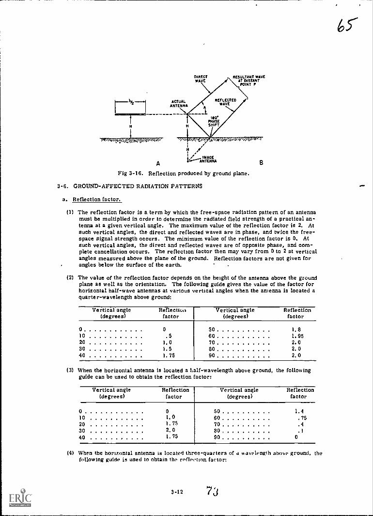
65'
AACTUALNTENNA
Ori%<`"/1/,(44,'V'iCe.W/ek'/AW
A
Fig 3-16. Reflection produced by ground plane.
DIRECT RESULTLNT WAVEWAVE AT DISTANT
POINT P
REFLECTEDWAVE
1.
PHASESHIFT
H
V------ANTtHf4A
3-6. GROUND-AFFECTED RADIATION PATTERNS
a. Reflection factor.
(1) The reflection factor is a term by which the free-space radiation pattern of an antennamust be multiplied in order to determine the radiated field strength of a practical an-tenna at a given vertical angle. The maximum value of the reflection factor is 2. Atsuch vertical angles, the direct and reflected waves are in phase, and twice the free-space signal strength occurs. The minimum value of the reflection factor is 0. Atsuch vertical angles, the direct and reflected waves are of opposite phase, and com-plete cancellation occurs. The reflection factor then may vary from 0 to 2 at verticalangles measured above the plane of the ground. Reflection factors are not given forangles below the surface of the earth.
(2) The value of the reflection factor depends on the height of the antenna above the groundplane as well as the orientation. The following guide gives the value of the factor forhorizontal half-wave antennas at various vertical angles when the antenna is located aquarter-wavelength above ground:
Vertical angle Reflection(degrees) factor
Vertical angle Reflection(degrees) factor
0 010 .520 1.030 1.540 1.75
50 1.860 1.9570 2.080 2.090 2.0
(3) When the horizontal antenna is located a kalf-wavelength above ground, the followingguide can be used to obtain the reflection factor:
Vertical angle Reflection(degrees) factor
Vertical angle Reflection(degrees) factor
0 0
10 1,020 1.7530 2.040 1.75
50 1.460 .7570 .480 .190 0
(4) When the horizontal antenna is located three-quarters of a wavelength above ground, thefollowing guide is used to obtain the reflection factor:
3-12

Vertical angle(degrees)
Reflectionfactor
0 010 1.520 2.030 1.540 0
I
I
1
!
!
Vertical angle(degrees)
Reflectionfactor
50 1.60 1. 770 1. 980 2.090 2. 0
(5) When a height of 1 wavelength above ground is used, the following guide shows the re-flection factor:
Vertical angle Reflection(degrees) factor
Vertical angle(degrees)
Reflectionfactor
0 0 50 1.95li) 1.8 60 1.420 1.6 70 .630 0 80 .140 1.6
i90 0
(6) The guides in (3), (4), (5) above can also be used with a half-wave vertical antenna.The height above ground is measured from the center of the vertical antenna. It isnecessary, however, to subtract the given valt,es of reflection factor from 2. Then,if the reflection factor given in the charts for a certain height and vertical angle is 1,the reflection factor for a vertical antenna is 2 minus 1, or 1. If the reflection factorfor the horizontal antenna is 2, the factor for the vertical half-wave antenna is 2 minus2, or 0. If the reflection factor for the horizontal antenna is 0, then the vertical an-tenna reflection factor is 2 minus 0, or 2.
b. Horizontal half-wave antenna.
(1) When the foregoing reflection factors are applied to the free-space radiation pattern ofa horizontal half-wave antenna, the patterns shown in figure 3-17 are produced. Pat-terns A, C, E, and G are the vertical radiation patterns in the plane of the antenna it-self. B, D, F, and H are the vertical radiation patterns in the plane which is at rightangles to the antenna,. Patterns A and B are for antenna heights of a quarter-wavelength,C and D are for antenna heights of a half-wavelength; E and F are for heights of three-quarters of a wavelength; G and H are for heights of 1 wavelength.
(2) Figure 3-18 permits a better visualization of the radiation pattern produced. Here theactual solid radiation pattern is shown for a horizontal half-wave antenna located a half-wavelength above ground. In the vertical plane at right angles to the antenna, D of fig-ure 3-17 shows two large lobes whose maximum values occur at an angle of 30 with thehorizontal. This pattern is reproduced in perspective at the upper left of figure 3-18.In the vertical plane which includes the antenna, C of figure 3-17 shows two small lobeswith maximum values occurring at an angle of about 40° with the horizontal. This pat-tern is reproduced in perspective at the upper right of figure 3-18. If these two planeviews are connected smoothly, the solid pattern shown in the center of figure 3-18 isproduced.
(3) In similar manner, solid radiation patterns can be visualized from the plane viewsshown in figure 3-17. Picture the pattern as being produced by the smooth transitionfrom one vertical plane view shown to the othi. r vertical plane view shown as an angleof 90* is covered.
(4) Although vertical patterns are shown for only four specific heights above ground, it isnot too difficult to predict the patterns produced at intermediate heights. This is truesince the patterns do not change abruptly as the height of the antenna is increased grad-ually. Instead, there must be a s nooth transition from the pattern shown for a heightof a quarter-wavelength to the pattern shown for a height of a half-wavelength.
3-13
74

l
(5) At heights less than a quarter-wavelength above ground, the vertical patterns producedby a horizontal half-wave antenna are almost perfectly circular. As the antenna israised, the vertical pattern is flattened somewhat at its top, at a vertical angle of 90'(B of fig 3-17). As the height is increased above a quarter-wavelength, a depressionbegins to appear at the top of the pattern, and the pattern width increases. The depres-sion grows deeper and deeper, and as the antenna height approaches a half-wavelength, thepattern splits into two separate lobes. The radiation at a vertical angle of 90' (straightup) is zero at this height, as in D of figure 3-17. As the antenna height increases stillmore, a lobe of radiation begins to grow out of the center of the pattern at a verticalangle of 90. As this lobe increases in amplitude with increasing antenna height,. thetwo side lobes are spread farther apart so, that their maximums occur at lower verticalangles. This vertical lobe has its maximum amplitude and begins to flatten somewhat(F of fig 3-17) at an antenna height of 3 quarter-wavelengths. As the antenna heightis increased still more, the vertical lobe develops a depression that grows deeper asthe height is increased. Finally, at a height of 1 wavelength, the center lobe splits intotwo separate lobes and the radiation at a vertical angle of 90 is again zero. Now fourdistinct lobes exist (H of fig 3-17).
(0 The patterns that are produced at antenna heights in excess of 1 wavelength also can bedetermined by studying figure 3-17. When the height of the horizontal antenna is an oddnumber of quarter-wavelengths above ground, a lobe of maximum radiation is producedat a vertical angle of 90' straight up.
(7) Consider an antenna with a height of 1 quarter-wavelength above ground. Assume thatthe instantaneous ele_tric field immediately ardund the antenna is maximum in a givendirection, designated as positive. A portion of this field moves downward at a distanceof a quarter-wavelength to the ground. Upon being reflected, a 180° phase shift occurs,and the instantaneous electric field is now maximum in the opposite direction, designatedas negative. This negative field now moves upward from the ground for a distance ofa quarter-wavelength. By the time the reflected field returns to the antenna, a totaldistance of a half-wavelength has been covered. Meanwhile, since one-half cycle ofoperation has elapsed during the time required for the downgoing wave to move fromthe antenna to the ground and from the ground back to the antenna again, the polarityof the energy on the antenna itself has reversed. As a result, the reflected wave arrivesback at the antenna in exactly the right phase to reinforce the direct wave. The rein-forcement occurs not only at heights of a quarter-wavelength above ground, but also atheights of three-quarters of a wavelength, and so on. Consequently, a lobe of maximumradiation is produced at a 90° vertical angle for all antenna heights which are an odd num-ber of quarter-wavelengths from ground.
(8) When the height of the antenna is an even number of quarter-wavelengths above g.ound,a null (zero radiated energy) occurs at the 90' vertical angle. Consider the action ofthe horizontal half-wave antenna that is located at a distance of a half-wavelength aboveground. The portion of the radiated field from this antenna which travels downward to-ward the ground must cover a total distance of 1 wavelength before it arrives back atthe antenna. The direction of this field is reversed by the reflection process. Duringthe time that is required for the reflected wave to cover the distance, the field immedi-ately surrounding the antenna has gone through 1 complete cycle and is now back to itsoriginal direction or polarity. The reflected wave, therefore, with its field reversedby the reflection process, becomes 180' out of phase with the direct wave from the an-tenna. As a result, cancellation occurs at the vertical angle of 90', and a null is pro-duced. This cancellation, as described above, occurs not only at heights of a half-wave-length above ground, but also at heights of 1 wavelength, 1 wavelengths, and so on.Consequently, null is produced at a 90' vertical angle for all antenna heights which arean even number of quarter-wavelengths from ground.
(9) One other factor can be observed from the patterns in figure 3-17, which can be used todetermine the vertical radiation pattern of a horizontal half-wave antenna at heights great-er than are shown. At a height of 1 quarter-wavelength above ground, the radiation pat-tern is seen to consist of one lobe only. At a height of a half-wavelength (X12) aboveground, the radiation pattern consists of two lobes. At a height of three-quarters of awavelength, the pattern consists of three lobes. At a height of a full-wavelength (X) aboveground, the radiation pattern consista of four lobes. Consequently, the number of ver-tical lobes produced is numerically equal to the height of the antenna above ground
.... ..
3-14
75
67

iti quarter-wavelengths and continues for any antenna height. It is possible to get afairly good idea of the vertical radiation pattern of a horizontal half-wave antenna atany height above ground, For example. if the antenna is located at a height of 2 wave-lengths above ground, which is an even number of quarter-waves, a null is produced ata vertical angle of 90*, Then, since 2 wavelengths represent 8 quarter-wavelengths, theradiation pattern consists of eight lobes,
Fig 3-17. Vertical-plane radiation patterns of horizontal half-wave antennas.

bq
...
ANTENNAAXIS
Fig 3-18. Radiation pattern of a horizontal half-wave antennalocated a half-wavelength abn ground,
C. Vertical half-wave antenna.
(1) When the proper reflection factors are applied to the free-space radiation pattern of avertical half-wave antenna, the patterns shown in figure 3-19 are produced. Only asimple plane view need be shown here because the vertical half-wave antenna is non-directional in the horizontal plane. Its free-space horizontal radiation pattern is a cir-cle. Therefore the effect of the reflection factor is the same in all horizontal directions.
(2) To visualize more clearly the solid radiation pattern, it is necessary only to picture theplane patterns (fig 3-19) being rotated. One such solid radiation pattern is shown infigure 3-20, where the pattern is produced by a vertical half-wave antenna the centerof which is a half-wavelength above ground.
(3) In general, two effects are shown when the patterns of figure 3-19 are observed. First,there is always a null at the vertical angle of 90 because there is no radiation fromthe end of the vertical antenna. Therefore, regardless of the value of the reflectionfactor at this angle, no radiation occurs directly upward. At all antenna heights, then,the vertical half-wave antenna produces a null at 90. The second effect noted is that,25 the antenna is raised above ground, a greater number of lobes appears in the pattern.At a height of 1 quarter-wavelength, for example, two lobes appear (A of fig 3-19!.When the antenna is raised to 1 half-wavelengtn, four lobes appear, as in B. The am-plitude of the upper lobes is much smaller than that of the lobes which lie along theground. At a height of three-quarters of a wavelength, there are still four lobes, but theamplitude of the upper lobes hal increased, as shown in C. When the antenna is raisedto a height of a full wavelength, as in D, six lobes appear.
3-16

A
Fig 3-19. Vertical-plane radiation patterns produced by vertical half-wave antennas.
ANTENNAAXIS
,
"44/31ligirr'
v,;'
1.1...er,
Fig 3-20. Radiation pattern of a vertical half-wave antennalocated a half wavelength above ground.
3-7. SINGLE-WIRE ANTENNA
a. General.
(1) A single-wire half-wave antenna is one constructed of a single conductor of properlength. In the high-frequency range, the conductor is usually a stranded copper-alloywire which is suspended between two upright supports. In the vhf and uhf frequencyranges, aluminum tubing frequently is used, and the antenna length is sufficiently shortthat the tubing need be supportad only at the center.
3-17
78

(2) The single-wire antenna can be mounted either vertically, to produce a vertically polar-ized radio wave, or horizontally, to produce a horizontally polarized wave.
b. apL!!
(1) The typical military half-ware antenna (fig 3-21) is suitable for transmission and recep-tion. It can be used in conjunction with a transmitter having an output power of lessthan 100 watts. All of the component parts required for the installation are furnishedin kit form. When the antenna is disassembled, it is highly portable.
(2) Sufficient antenna wire is provided to construct a half-wave antenna resonant to a fre-quency as low as 1.5 MHz, that is 312 feet long. If the antenna is to operate on a fre-quency as high as 18 MHz, the length is shortened to 24.3 feet.
(3) A single-wire transmission line can also be used with this antenna. The single-wireline is connected at a point 0.18-wavelength from one end of the antenna, giving it aproper impedance match.
Fig 3-21. Single-wire antenna.
3-8. FOLDED DIPOLE, COAXIAL, CONICAL AND MICROWAVE ANTENNAS
a. Folded Dipole.
(1) The folded-dipole antenna consists of an ordinary half-wave antenna (dipole) which hasone or more additional conductors connected acr)ss the ends of the antenna. The addi-tional conductors are mounted parallel to the dipole elements at a distance that is a verysmall fraction of a wavelength in which spacings of several inches are common (fig 3-22).In A, the 2-wire folded dipole is constructed of metal tubing. In B, the 3-wire foldeddipole is made of wire. The electrical length of both antennas is a half-wavelength.
(2) Consider first the simple, 2-wire folded dipole. Assume that the additional conductoris removed at points 1 and 2. Assume further that the charge remaining on the simplehalf-wave antenna is such that the end of the antenna at point 1 is maximum positive
3-18 7 9
7/

and the end of the antenna at point 2 is maximum negative. Ordinarily, current thenwould start to flow from point 2 toward point 1. Now, if the additional conductor isconnected as shown in the figure, this current finds two paths available. Consequently,the current divides so that about half flows from right to left in the additional conductorand the remaining half flows in the same direction in the lower conductor, making upthe simple half-wave antenna. This occurs with no change in input power.
(3) Since impedance varies inversely as the square of the current (ZzP/I2), a reduction inthe current flowing in that branch of the folded dipole to which the transmission line isconnected results,in aa increase in the input impedance of the antenna. As the currentis reduced to half its original value, the impedance of the antenna increases to fourtimes 73 ohms, or close to 300 ohms. Therefore, a 300-ohm transmission line can beconnected to the folded dipole, and a correct impedance match occurs.
7;2-
(4) If three conductors are used instead of two, a given input power will produce only one-third the original current in each conductor. As a result, the input impedance of theantenna rises to nine times 73 ohms, or about 600 ohms. This provides the properimpedance match for an ordinary-600-ohm transmission line, and the folded-dipole an-tenna provides an impedance step-up that can be used to produce an impedance match tocommon transmission lines.
3C011LINE
A40011UNE
Fig 3-22. Folded-dipole antenna.
b. Coaxial antenna. The coaxial or sleeve antenna is a common vertical radiator that is used
in the vhf and uhf bands. In figure 3-23, the typical military coaxial antenna consists of a verti-
cal half-wave antenna so constructed as to provide a convenient, mechanical feed arrangement.
The antenna is fed by means of a flexible coaxial cable which runs up through the supporting staff.
(1) The inner conductor of the coaxial cable is connected to the upper portion of the an-
tenna, designated as the whip. The outer conductor of the cable is connected through
a shorting ring to the top of an outer skirt. This skirt or sleeve is a hollow metal cyl-
inder mounted around the outside of the mounting staff which supports the antenna. A
small air space exists between the skirt and the outer surface of the mounting staff,
except at the location of the shorting ring. The skirt then acts as the lower portion of
the antenna,
(2) The skirt has an additional function. In conjunction with the outer surface of the metal
mounting staff, it forms a quarter-wave section of transmission line which is short-
circuited at one end by the shorting ring. The impedance at the bottom end of the line
so formed is very high. As Et result, current flow is minimized on the mounting staff
and on the outer conductor of coaxial cable. Such current, if allowed to flow, would
produce radiation at a high vertical angle. By reducing this current to a minimum val-
ue, the radiation is reduced. In this way, the low-angle line-of-sight transmissionrequired in the vhf and uhf bands is produced.
(3) Thedimensions of the whip and especially of the skirt are highly critical. The upper
radiating portion (whip) (DIM A, fig 3-23) is made 95 percent of a free-space quarter-wavelength. The length of the lower radiating portion (skirt) (DIM B) is made equal to
a iree-space quarter-wavelength. Actually, the skirt should be somewhat shorter thanthis value to produce maximum efficiency as a radiator. Its length, however, is chosenfor best operation as a quarter-wave line, which produces slightly higher radiation
efficiency. Adjusting clamps are provided both for the skirt and for the whip so that
the antenna may be adjusted for any frequency in a given band.
3-19
o

(4) One particular military coaxial antenna has a frequency range of from 30 to 40 MHz.Another military coaxial antenna has a frequency range of 70 to 100 MHz. Markingssometimes are provided on the elements themselves to show the correct whip and sleevelengths for various resonant frequencies. For example, a coaxial antenna suitable for35 MHz would have a whip length of 80 inches and a skirt length of 84 inches.
DIM A
DIM
ADJUSTABLE PORTIONOF WHIP
ADJUSTING CLAMP
FIXED reenceOf WHIP
WHIP IS SCREWED TOSKIRT ASSEMBLY ATTHIS POINT
INSULATOR
HOISTING BRACKET
SHORTING RING
FIXED PORTIONOf SKIRT
ADJUSTING CLAMP
PLUG
O./
c. Conical antenna.
ADJUSTABLE PORTIONOF SKIRT
MOUNTING STAFF
RACKETS FOR STRAPPINGANTENNA TO MAST
PROTECTING SPRING
COAXIAL CABLE
Fig 3-23. Military coaxial antenna.
(1) The conical antenna is one of a large number of special antennas developed to operatesatisfactorily over a wide frequency band. One type of conical antenna, constructed oftwo solid metal cones, is shown in figure 3-24. Frequently the conical antenna is con-structed of metal mesh or is simply a framework of metal rods that form the requiredshape. The cones are arranged on a common horizontal or ye, tical axis, dependingon whether horizontal or vertical polarization is required.
(2) If the conical antenna is to operate as a half-wave antenna, its overall length must beconsiderably shorter than a free-space half-wavelength. This is the result of the largeend effect produced by the bases of the cones formine the antenna. As the &pex angle,A, is increased, the length of antenna required is reduced. For example, if angle A is10, the overall length required is about 75 percent of a free-space half-wavelength.With angle A at 20, the length is only about 70 percent of a free-space half-wavelength.When such short lengths are used, the input impedance is approximately 40 ohms.When the conical antenna is operated as a full-wave antenna, the o%erall length com-monly is made 73 percent of a free-space wavelength and the input impedance is ...ever-al hundred ohms. When such an antenna has an apex angle of 10', the input impedanceis 950 ohms; with an apex angle of 20', the input impedance is 600 ohms, v. ith an apeNangle of 30', the mput impedance is 300 ohms. The value may be rduced by usinglarge apex angles, in excess of 30'.
3-20

?/(3) The large, cross-sectional area of the conical antenna accounts for its wide frequency
response. Like the folded dipole, the conical antenna has a large capacitance but asmall inductance per unit length. The radiation pattern of the conical antenna is similarto that produced by an ordinary half-wave antenna which is similarl:. oriented. Figur'.3-25 shows a typical military conical antenna.
TRANSMISSIONUNE
Fig 3-24. Simplified conical antenna.
,-H CROSS ARMS
S,r4i4,6 hos
4144/401,
ANTENNA MAST
ANTENNA
TRANSMISSION LINES
Fig 3-25. Military conical antenna.
d. Microwave antenna.
The half-wave antenna can be used at any operating frequency. When microwave frequen-cies (at the upper part of the uhf band and higher) are used, Ihe antenna length required is ex-tremely small. For example, the microwave frequency of 5,000 MHz has a free-space half-wavelength of only little more than 1 inch. The length of the half-wave antenna at this frequencywould have a value somewhat less than this small distance.
The small size of a microwave, half-wave antenna is both a disadvantage and an advan-tage. The electrical characteristics of the microwave antenna are exactly like those of itslarger, lower frequency counterpart. It has about the same radiation patter n, the same dis-tribution of standing waves along its length, and the same radiation resistan, e for similar con-ditions. However, the amount of signal pick-up when such a small antenna is used for receivingis reduced greatly. Any receiving antenna is able to pick up energy from a section of an incom-ing wave front that extends less than a quarter-wavelength away from the antenna. Therefore,a receiving antenna that is 50 to 100 feet long is able to pick up a far greater amount of energythan can a microwave antenna only about an inch in length. So poor is the signal pick-up that asimple, half-wave antenna rarely is able to pick up enough microwave energy to overcome thenoises generated within the receiver itself. As a result, a simple, half-wave antenna seldomis used alone in the microwave range.
3-21 82

The great advantage of the small size of microwave, half-wave antennas is that it becomesconvenient to use a large number of these together to form an array of antennas. All antennaarrays have two things ii. common. First, an array produces a concentration of radiated energyin certain directi-os; that is, the array is highly directionalit has gain. Second, an arrayoccupies a greater space than does the single half-wave antenna, since it is made up of a numberof half-wave antennas, and the greater the number of individual antennas that make up thearray, the greater are the directivity and gain. In the microwave range, the construction ofvery elaborate arrays of half-wave antennas can be accomplished in a reasonably small space.Some microwave arrays are made up of as many as 32, 64, 100, or even 250 individual half-wave dipoles.
Other microwave antennas are composed of a single hali-wave dipole or an array that isused in conjunction with specially shaped reflectors.
One commonly used reflector, shown in A of figure 3-26, is the corner reflector type.The reflector is composed of two flat, metal sheets which meet at an angle to form a corner.Wire mesh or metal tubing sometimes is used instead of the solid metal. The half-wave, micro-wave antenna is located so that it bisects the corner angle because maximum radiation occursout of the corner. The field strength produced by such an arrangement is considerably morethan would be produced by the antenna alone.
Another commonly used reflector is the paraboloidal type (fig 3-26 B). The shape is sim-ilar to that a reflectors used in searchlights that concentrate energy from a light bulb into anarrow, well-defined beam. The reflector is constructed of solid metal or metal meah. A half-wave, microwave antenna is located at the focal point of the parabnloid. Energy arriving at anyangle from the antenna is reflected by the paraboloid in parallel rays. This results in a verynarrow beam of radio energy in the direction shown. A small, metal, hem.opherical reflectorprevents direct radiation from the hali -wave antenna from interfering with the beam producedby the paraboloidal reflector. The small reflector causes all of the energy from the antenna tobe directed back into :he paraboloid.
IC Enna
COAXIAL OR*AMU=
FEED MAXIMUMRADIATION
SHEET REFLECTORS
DIPOLEHEMISPHERICAL
AEFLEcronANTENNA A 8
Fig 3-26. Special reflectors for half-wave antennas.
3-9. MULTIELEMENT ARRAYS
One means of attaining increased antenna gain and directivity is by use of the multiolementarray. The long wire, regardless of its length, is looked upon 115 a single radiating or receivingelement; the array is a combination of elements which, considered separately, could be mdividualantennas. These elements act together or upon each other to produce a given radiation pattern.Various factors influence the choice of methods used to produce high directivity. Whereas the long-wire antenna often is preferred where reception or transmission on more than one frequency isrequired and where gain or directivity requirements are moderate, the more exact phasing anddetermination of element lengths in the array make for a more regular radiation pattern. Sincefewer minor lobes are developed, available power is concentrated in the major lobe or lobes, andtherefore there is greater gain 2nd sharper directivity in the favorA direction. In a given availableapace, the elements of an array can be so arranged as to provide greeter gain than a long-wireantenna conftned to the same space.
a. Parasitic array. Of the several types of multielement array antennas the one we willconcera ourselves with is the parasitic array. Definitions for ternia uscd in this paragraph areas follows;
3-22
8 3
7 5

7 4,(1) Driven element. A driven element is connected directly to the transmission line. It
obtains ite power directly from the transmitter or, in reception, it applies the receivedclergy directly tc the receiver.
(2) Parasitic element. A parasitic element derives its power from another element in thearray. It is not connected to any other element but is placed close enough to receiveradiation and in this way is excited.
(3) Director element. This is a parasitic element placed in front of the driven element so thatit operates to reinforce the radiation from the driven element (fig 3-27A).
(4) Reflector element. This is a parasitic element placed to the rear of the driven element sothat it operates to reflect the radiation back to the driven element, thereby reinforcingthe radiation fromit (fig 3-27B).
T---- =====esoottcron
MOIR A
"F"-- c==1
mots
DORM(UMW
FLECTOR
Fig 3-27. Position of the director and reflector to the driven element.
A parasitic array consists of one or more parasitic elements placed in parallel with eachother (fig 3-28).
Fig 3-2a. A parasitic array used for receiving and transmitting HF and LE%
b. Radiation. When a parasitic element is placed at a fraction of a wavelength feom the drivenelement, it will re-radiate the radiated energy it intercepts. The parasitic element is effectivelya tuned circuit coupled to the driven element much as the two windings of a transformer are coupled
together. The radiated energy from the drivcn element causes a voltage to be developed in theparasitic element which sets up a magnetic field. This niagnetic field extends over to the drivenclement, which then has a voltage induced in it. The magnitude anc; phase of the induced voltagedepend on the length of the parasitic elemt-nt and the spacing between the elements. The length
and spacing are arrang.3d so that the ()case and magnitude of the Induced voltage cause a unidirectional,
horizcatai radiation pattern.
3-23
8 4

(1) Consider the parasitic array in B of figure 3-27; the reflector and driven elements arespaced a quarter-wavelength apart. The radiated signal coming from the driven elementstrikes the reflector after a quarter-cycle. This causes the voltage on the reflector to be1800 out of phase with the driven element.
(2) The reflector now sets up a magnetic field which induces a voltage back to the driven element.This voltage is now in phase with the driven element voltage and reinforces the radiatedsignal.
(3) The director in A of figure 3-27 gives the antenna directivity so that the radiation patternsof both A and B of figure 3-27 appear as shown in figure 3-29.
HORIZONTAL PATTERNS
IRADIATEDSIGNAL
VERTICAL PATTERNS
/RADIATEDSIGNAL
DIRECTOR RECTOR
DRIVEN DRIVENLEMENT UREIC(
PATTERNS MAINE!) USING DIRECTOR
IRADIATEDSANAA.
IRADIATEDSIGNAL
A
ENLEMENT
soREILECTOR RI/LECTOR
PATTERNS MAIMED USING REFLECTOR
Fig 3-29. Patterns obtained using a parasitic element.
c. Directivity. Directivity is achieved through the length of the elements, the space betweenthe elements, and the number of elements used in the array.
(1) If the array contains two parasitic elements (a driven element, a reflector, and a director),it is known as a three-element beam. If more directors are added, the higher the elementbeam will be. For example, a five-element beam will have a driven element, a reflector,and three directors. Most parasitic arrays do not exceed the five-element beam.
(2) Parasitic elementd are usually positioned as shown in figure 3-30. Section A shows a three-eleme:t beam, B a four-element beam, and C a five-element beam. Many variations maybe found, but the spacing between elements is typical of those normally encountered.Frequently tne best spacing is found experimentally. Regardless of the number ofdirectors on an array, only one reflector is used.
85
3-24
7 7

11111111....11144aus 4Mag.
NVIVIIIMILIICTO, SUMO, *crag
De,14--it-41%--A
a DI etOF... Il.,1%......444,4.46%....0
:-- llhZ.--,t16-441--s11.---41*-1-C
Fig 3-30. Spacing between elements of multiparasitic arrays.
(3) In a three-element beam, the director is slightly shorter and the reflector is slightlylonger than the driven element. As each director is added, it Is slightly shorter thanthe one nearer to the driven element.
Note: For more detailed information see TM 11-666, chapter 5.
3-25
86
75'
Chapter 4
LONG-WIRE ANTENNAS AND ANTENNA INSTALLATION
Section I. LONG-WIRE ANTENNAS
4-1, INTRODUCTI ON
71
Long-wire antennas are long single wires (langer than a half wavelength) in which thecurrent in adjacent half-wave sections flows in opposite directions. Such antennas have twobasic advantages over the antennas discussed previously. These advantages are increased gainand directivity.
a. Antenna gain.
(1) All the antennas discussed so far have been basic half- and quarter-wave antennas thatradiate equally in all directions. Greatest amounts of power are radiated in directionsthat are broadside to the antenna itself, and very little power is radiated off the antennaends. Consequently the basic antennas already discussed have a certain degree of direc-tivity, which is the ability to radiate and receive energy better in some directions thanin others.
(2) An isotropic antenna is one that radiated equally in all directions. Actually, every an-tenna radiates more energy in certain directions than in others. The imaginary isotrop-ic antenna can be used only as a standard for comparison.
(3) Since no antenna is truly isotropic, it is common practice to use a basic half-wave an-tenna as a standard for reference. The reference field strength is the field intensityat a fixed point produced by the half-wave antenna in the direction of its maximum radia-tion. The reference power is the power applied to the standard antenna. If any antennaproduces a greater field strength at the same fixed point than does the standard antenna,it is said to have gain with respect to the standard. Conversely, if the antenna producesless field strength at the fixed point than does the standard antenna, it is said to haveloss with respect to the standard.
(4) In practice, the procedure is first to set up the antenna to be checked. A given amountof input power is applied, and the field strength is measured at a distant receiving point.Then, the half-wave antenna is set up at the same position and height above the earth,and oriented so that a field having the same polarization as the original antenna is pro-duced. Exactly the same power is applied to the half-wave antenna as was applied tothe other antenna. The field strength then is measured at the same distant receivingpoint. Comparison between the two field strengths indicates whether the antenna beingchecked produces a gain or loss in field strength compared with the reference antenna.
(5) Another method used to measure the gain (or loss) of an antenna involves an actual meas-urement of the input power to the antenna. The amount of input power applied to the an-tenna to be checked is measured, the field strength at a certain distant point is noted,and the half-wave antenna is set up in the preceding method. The power applied to thisreference antenna then is adjusted until exactly the same field strength is produced atthe distant point. If more power must be applied to the reference antenna to producethe same field strength at the point as produced by the antenna under test, the antennaunder test has a Eirl with respect to the reference antenna. On the other hand, if lesspower must be applied to the half-wave reference antenna to produce the same fieldstrength, the antenna under test has a loss with respect to the reference antenna. Theratio between the two input powers (reference antennas divided by tested antennas) givesthe:, gain (or loss) of the antenna being tested. Because an accurate measurement of dif-ferent field strengths cannot be made as easily as an accurate measurement of differentantenna input powers, this method is preferred to that described in (4) above.
(6) If a certain antenna has a gain of 10 dB, it produces a field strength that is over threetimes greater than that produced by the half-wave antenna with the same input power.This antenna produces the same field strength 2S that produced by the half-wave an-tenna when the power applied to the half-wave antenna is 10 times greater than thatapplied to the antenna under test.
4-1
8 7

ro
b. 1:_tiyity,
(1) Since all antennas are directional to a certain degree, -the term directional usually isapplied only to those antennas that are highly directional. The main advantage to begained from the use of the long-wire antennas and arrays is in their greater direction-al qualities. These antennas all concentrate a larger amount of available radiated ener-gy into a smaller sector.
(2) Some antennas are directional in some planes but practically nondirectional in others.Consider, for example, the basic half-wave antenna that is mounted in a vertical posi-tion. If a vertical plane is passed through the center of the antenna and the radiationpattern is drawn on that plane, the pattern would take the form of a figure 8. Maxi-mum radiation occurs in the two directions that are at right angles to the anteana itselfand no radiation occurs off the ends. The antenna is said to have two lobes of radiatedenergy and two nulls. Consequently, this antenna is said to be bidirectional (it radi-ates in two directions) in the vertical plane. If the horizontal plane is considered, how-ever, it is seen that the antenna radiates equally in all directions. The antenna there-fore is nondirectional in the horizontal plane. When highly directional antennas areused, it is important to know in which plane the desired directivity occurs.
(3) Highly directional antennas are designed to produce a large increase in radiated or re-ceived energy in one direction. The idea, however, may be to prevent radiation (orreception) in a certain direction. For examile, assume that two powerful transmittersare located near each other. To prevent these transmitters from interfering with eadiother, it is necessary to use directional antennas with respective nulls pointing towardeach other. Under these conditions, the antennas may be adjusted to produce the leastamount of radiated energy in the direction of each other, rather than the greatestamount of energy in any given direction.
4-2. GENERAL CHARACTERISTICS
a. Harmonic. If the length of a long-wire antenna is such that two or more half-waves of energyare distributed along it, it often is referred to as a harmonic antenna. Consider the half-waveantenna shown in A of figure 4-1. At a given instant, the polarity of the lir generator connectedto the center of the antenna is positive at its left-hand terminal and negative at its right-handterminal. As a result, current in the left half of the antenna flows toward the generator, where-as current in the right half of the antenna flows away from the generator. In both halves of thehalf-wave antenna, current flows in the same d.rection, from left to right, as shown by the waveof current above the antenna wire.
b. Nonharmonic. Now assume that the antenna ju,-t discussed is lengthened until it is 2 half-wavelengths, as in B. With the RF generator still connected at the center and with the sameinstantaneous polarities as in A, current in the left side of the antenna must flow toward the gener-ator, and current in the right side must flow away from the generator. Since the antenna is now 2half- wavelengths, 2 half-waves of current can be accommodated on the antenna and the current polar-ity is the same in both halves of the antenna. It is important to note that this is not a true longwire or harmonically operated antenna since there is no reversal of current flow in adjacenthalf-wave sections. Instead, this arrangement is simply 2 half-wave antennas operating in phaseat their fundamental frequency. Such an arrangement is called a driven e, ar array, andhas characteristics quite different from those to be discussed for the trte_ inonically operatedor long-wire antenna.
The antenna in B can be converted into a true long-wire, harmonically operated antennasimply by moving the generator to a current loop as shown in C. With the RF generator polar-ity as shown, current flows from left to right in the half-wave section of the antenna. The direc-tion of current flow then is reversed in the second half-wave section. If the generator ismoved to the extreme end of the antenna as shown in D, the antenna is also a long-wire antenna,and the current distribution on the antenna Is exac''y the same as in C.
The harmonically operated antenna, therefore, must be fed either at a current loop or atits end for proper operation. If the antenna is any odd number of half-wave lengths (11,and so ri) so that a current loop occurs at the cenier of the antenna, center feeding can be used.
As the length of an antenna 13 increased, it is natural to expect a change in the radiationpattern produc ed by the antenna. A long-wire antenna c an be consiuered one made up of a num-ber of half-wave seLtions fed 180' out of phase ari 5p2,7t.d a half-waveiength apart. As a result,
4-2
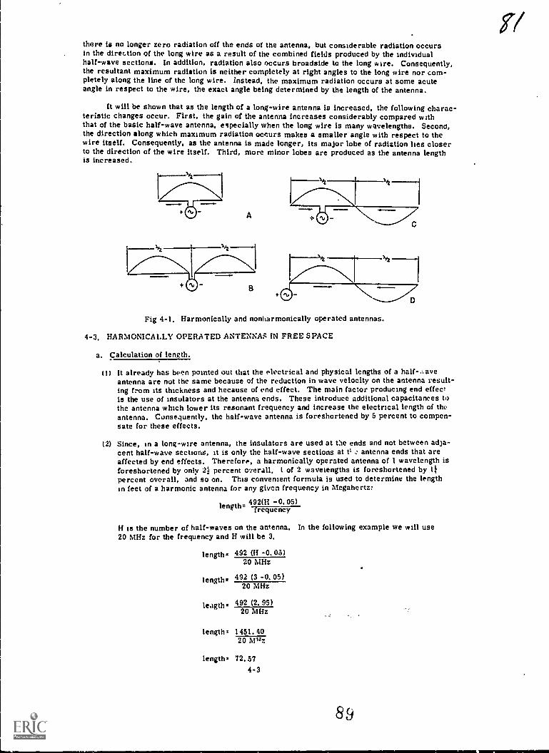
there is no longer zero radiation off the ends ot the antenna, but considerable radiation occursin the direction of the long wire as a result of the combined fields produced by the individualhalf-wave sections. In addition, radiation also occurs broadside to the long wire. Consequently,the resultant maximum radiation is neither completely at right angles to the long wire nor com-pletely along the line of the long wire, instead, the maximum radiation occurs at some acuteangle in respect to the wire, the exact angle being determined by the length of the antenna.
It will be shown that as the length of a long-wire antenna is increased, the following charac-teristic changes occur. First, the gain of the antenna increases considerably compared withthat of the basic half-wave antenna, especially when the long wire is many wavelengths. Second,the direction along which maximum radiation occurs makes a smaller angle with respect to thewire itself. Consequently, as the antenna is made longer, its major lobe of radiation lies closerto the direction of the wire itself. Third, more minor lobes are produced as the antenna lengthis increased.
A
1
'7Fig 4-1, Harmonically and nonharmonically operated antennas.
4-3. HARMONICALLY OPERATED ANTENNAS IN FREE SPACE
a. Calculation of length.
(1) It already has been pointed out that the electrical and physical lengths of a half-...aveantenna are not the same because of the reduction in wave velocity on the antenna result-ing from its thickness and hecause of end effect. The main factor producing end effectis the use of insulators at the antenna ends. These introduce additional capacitances tothe antenna which lower its resonant frequency and increase the electrical length of theantenna. Consequently, the half-wave antenna is foreshortened by 5 percent to compen-sate for these effects.
(2) Since, in a long-wire antenna, the insulators are used at the ends and not between adja-cent half-wave sections, it is only the half-wave sections at t% antenna ends that areaffected by end effects. Therefore, a harmonically operated antenna of I wavelength isforeshortened by oniy 21; percent overall, 1 of 2 wavelengths is foreshortened by 11percent overall, and so on. This convenient formula is used to determine the lengthin feet of a harmonic antenna for any given frequency in Megahertz:
492(11 0.05)length- trequency
H is the number of half-waves on the antenna. In the following example we will use20 MHz for the frequency and H will be 3.
length= 492 (H -0.05)20 MHz
length= 492 (3 -0.05)20 MHz
leagths 492 (2* 95)20 MHz
lengthz 1451.4020 Wiz
length. 72.574-3
89

L
b. Radiation patterns.
(I) Figure 4-2 shows the radiation patterns of harmonic antennas up to 3 wavelengths. Thefield strength produced by the half-wave antenna is shown for comparison. Note that asthe antenna length is increased, more lobes are produced. The li-wavelength antenna,which operates on the third harmonic, has three lobes--tw, major lobes and one minorlobe, the latter lying at right angles to the antenna. The 3-wavelength antenna, whichoperates on the 6th harmonic, has 6 lobes--2 major lobes and 4 minor lobes.
(2) The harmonic antennas which operate on the even harmonics (2d, 4th, and so on) havean even number of half-wave patterns distributed along their length. Since the adjacenthalf-wave sections have currents of opposite phase, a distant point in space locatedequidistant from the ends of the antenna is acted on by equal and opposite fields. Cancel-lation of fields occurs and a null is produced on a plane at right angles to the antenna,cutting it at the center. On the other hand, harmonic antennas which operate on the oddharmonics have an odd number of half-wave sections. Complete cancellation of radiatedfields does not occur at points equidistant from the ends of the antenna because of the oddhalf-wave section. This results in a minor lobe being produced in a direction that isperpendicular to the antenna, and coming from its center.
N.2
FUNDAMENTAL
X20 H2RMONIC
30 HAIMONIC
2%4Th HARMONIC
2I12X5TH HARM01.0C
3%OH HARMONIC
Fig 4-2, Radiation patterns of various harmonic antennas.
(3) The radiation patterns of a harmonic antenna are modified considerably by the presenceof the earth under the antenna. Some of the energy radiated from the antenna travelsdownward toward the earth, where it is reflected, If the reflected energy arrives at somedistant point in phase with the direct energy from the antenna, then reinforcement of thesignal strength occurs. On the other hand, if the reflected energy arrives 1800 out ofphase with the direct energy, a reduction or cancellation of signal strength takes place.
(4) Energy reflected from ground will induce a voltage into the harmonic antenna. Thiscauses a current to flow ,.hich combines with the original antenna current. The totalantenna current then will be greater or less than the original antenna current, dependingon the height of the antenna. Consequently, the radiation resistance of the harmonicantenna varies, depending on the height above ground. Iti this respect, the behavior ofthe harmonic antenna is the same co the i.alf-wave antenna.
4-4, END FEEDING LONG-WIRE ANTENNAS
Both resonant and nonresonant lines can be used to feed long-wire antennas. The samegeneral principles apply here as In the half-wave antennas. A current-fed antenna behaves as atrue long-wire only at odd harmonics of the original frequency. Therefore, for operation on allharmonics, end feeding is preferred.
4-4 90
5G
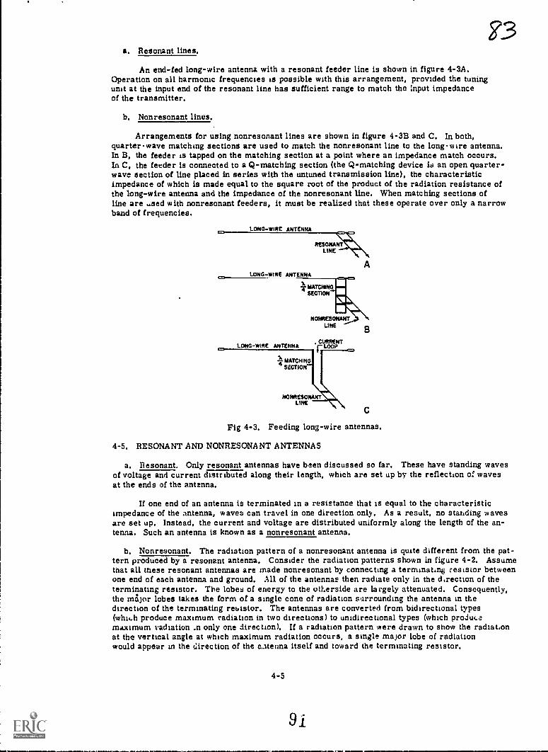
F3a. Resonant lines.
An end-fed long-wire antenna with a resonant feeder line is shown in figure 4-3A,Operation on all harmonic frequencies is possible with this arrangement, provided the tuningunit at the input end of the resonant line has sufficient range to match the Input impedanceof the transmitter,
b. Nonresonant lines.
Arrangements for using nonresonant lines are shown in figure 4-3B and C. In both,quarterwave matching sections are used to match the nonresonant line to the long-wire antenna.In B, the feeder is tapped on the matching section at a point where an impedance match occurs.In C. the feeder is connected to a Q-matching section (the Q-matching device is an open quarter-wave section of line placed in series with the untuned transmission line), the characteristicimpedance of which is made equal to the square root of the product of the radiation resistance ofthe long-wire antenna and the impedance of the nonresonant line. When matching sections ofline are used with nonresonant feeders, it must be realized that these operate over only a narrowband of frequencies.
LONG-WIRE ANTENNA
LONG-WIRE ANTENNA
TMATCIV40MOTION
LONG-WIRE ANTENNA
NONRESONANTLINE
MATCHING4 seams
NONRESONAKTLINE
Fig 4-3. Feeding long-wire antennas.
4-5. RESONANT AND NONRESONANT ANTENNAS
a. Resonant. Only resonant antennas have been discussed so far. These have standing wavesof voltage and current distributed along their length, which are set up by the reflection of wavesat the ends of the antenna.
If one end of an antenna is terminated in a resistance that is equal to the characteristicimpedance of the antenna, waves can travel in one direction only. As a result, no standing wavesare set up. Instead, the current and voltage are distributed uniformly along the length of the an-tenna. Such an antenna is known as a nonresonant antenna.
b. Nonresonant. The radiation pattern of a nonresonant antenna is quite different from the pat-tern produced by a resonant antenna. Consider the radiation patterns shown in figure 4-2. Assumethat all these resonant antennas are made nonresonant by connecting a terminating resistor betweenone end of each antenna and ground. All of the antennae then radiate only in the direction of theterminating resistor. The lobes of energy to the otherside are largely attenuated. Consequently,the major lobes takes the form of a single cone of radiation surrounding the antenna in thedirection of the terminating resistor. The antennas are converted from bidirectional types(whih produce maximum radiation in two directions) to unidirectional types (which producemaximum radiation .n only one direction). If a radiation pattern were drawn to show the radiationat the vertical angle at which maximum radiation occurs, a single major lobe of radiationwould appear in the direction of the catenna itself and toward the terminating resistor.
4-5

An important characteristic of a nonresonant antenna is that it radiates efficiently over avery wide frequency range. Therefore, it is not necessary to cut the antenna for any exact lengthso long as it is at least several wavelengths.
4-6. BEVERAGE OR WAVE ANTENN*
a. Description and design.
(1) One type of nonresonant, long-wire antenna is the Beverage or wave antenna (fig 4-4) whichconsists of a single wire (preferably of 2 or more wavelengths) parallel with the earth andsupported on poles at a height o' 10 to 20 feet aVve ground. The far end of the wire isconnected to ground through a noninductive resistor of about 500 ohms. This resistormust be able to dissipate about one-third of the power fed into the antenna. This isabout the characteristic impedance of a single-wire transmission line with a groundreturn. A reasonably good ground, such as a number of ground rods or a counterpoise,should be used at both ends of the antenna.
CURRENT
DIRECTION OF TRANSMISSION
FRONTS es-.....41 i I
1 I I II 1NI //
SAIT/1k: 1 I i
I /I
/
I
/I /I
/
///
// /I /I
RESISTANCE
fERMINATIND
/ // / / // / // / / / / I /
C000 GRO/ / / / / W/ ./ ,v ' ,V4,A7 9./ 9,--a
4/#1"0
NIGH RESISTANCE GROUNO
Fig 4-4. Beverage or wave antenna.
(2) Sometimes two or more antenna wires are used in parallel instead of a single wire.This reduces the characteristic impedance of the antenna and ground-return circuit andpermits a lower value of terminating resistance to be used. The input impedance of theantenna is reasonably constant with frequency, and the antenna may be used over a widefrequency range without changing its length.
(3) The wave antenna th directional, and is used primarily for either transmitting or re-ceiving low-frequency signals. Maximum reception or radiation is in line with the wireand off the terminated end. There is a minimum of radiation in the opposite directionif the antenna is terminated properly. The forward lobe may be made narrower and thegain increased by using a longer antenna wire. However, if extremely long-wave anten-nas are used, the forward gain falls off.
(4) At frequencies below 800 kilohertz, a properly located wave antenna should give resultsequivalent to a vertical antenna several hundred feet high. One particular military waveantenna (fig 4-5) consists of three conductors arranged in the form of an equilateraltriangle 5 feet on a side, erected about 15 feet above ground on short telephone poles,and usually of 2 wavelengths. At a frequency of 500 kilohertz, such an antenna wouldbe almost 4,000 feet long. If ground space limitations prevent the use of such a longantenna, an antenna under 1 wavelength can be used. A reduction of forward gain willresult under these conditions.
4-8

t..., ..1"-'
Fig 4-5, Three-wire wave antenna.
b. Wave tilt.
(1) The operation of the wave antenna depends on a process known as wave tilt. When avertically polarized radio wave travels over the surface of an imperfect conductor, suchas the earth, the wave fronts lean forward in the direction of propagation. This is causedby the slower propagation constant of the earth. The amount of forward tilt depends onthe frequency of the R F wave and the characteristics of the surface over which the waveis traveling. Atjhe lower frequencies at which the wave antenna is used, the wave tiltis approximately proportional to the square root of the product of frequency and soilresistivity. As the resistance of the surface is increased, the wave travel along thesurface is reduced and a greater wave tilt results. Consequently, over rocky and sandysoil, a considerable forward tilt results, whereas over salt marshes and sea water,almost no tilt occurs. This means that wave antennas, which depend on wave tilt forproper operation, should not be installed over highly conducting surfaces, but, instead,should be installed only over poor or medium soil. Wave antennas also give good resultswhen installed over ground which has a permanent layer of ice (such as permafrost) ashort distance below the surface, or over certain types of ground found in northern orpolar regions which are very moist in the summer and have poor conductivity becauseof lack of mineral content. Actually, it is the average ground conductivity for a con-siderable distance below the surface that is important rather than the character of a thintop-soil layer.
(2) The wave antenna operates in conjunction with ground, so that a vertically polarizedradio wave is radiated. However, because of the forward wave tilt, there is a horizontalcomponent of the electrical field. The vertical and horizontal components are not exactlyin phase, and the resultant polarization of the radiated wave, therefore, is a long oval.The wave is radiated in the direction of the tilt which is off the end of the antenna thatis terminated in the resistance load (fig 4-4).
(3) Since the wav antenna is a grounded antenna with a wide frequency range, it usually isfed by means of an unbalanced, nonresonant transmission line. The input impedanceof the single-vire antenna is approximately 300 ohms, so that the characteristic im-pedance of the line also must be 500 ohms,
4-7
.
93

i6(4) The most common feeding arrangement is a single-wire transmission 1ie connected to
the end of the antenna. If coaxial line is to be used, an impedance-matcliing transformeris inserted between the transmission line and the antenna.
4-7. V ANTENNA
a. Description and design. Tne V antenna consists of two horizontal, long wires at:ranged toform a V, and fed at the apex with currents of opposite polarity. Major lobes from each wirecombine in such a way that maximum radiation occurs in the direction of a line th,,t bisects theangle between the two wires. Figure 4-6 shows a V antenna with the individual radiation pat-terns of each of the wires. The shaded lobes produced by each individual leg of the V lie inexactly the same direction. These lobes combine to form the shaded lobes in the resultant pat-tern. Most of the other lobes are more or less attenuated. The pattern is bidirectional, andradiation occurs along a line that bisects the apex angle in both directions. As with other long wireantennas, the greater the leg length the higher the gain and directivity of the antenna. The gain ofthe V antenna is about twice that of a single long-wire antenna, since the radiation from the lobesof two wires combines to produce the radiation pattern of the V antenna. In practice, the gain maybe even higher than this value because of the effects of one leg of the V on the other.
41iraent 44\1 ,...../4400:60WAINOWAR,
RESULTANT PATTERNASO TARECTMTY
Fig 4-6. Formation of the V antenna radiation pattern.
b. Radiation pattern. The optimum apex angle for the V antenna is, ordinarily, twice theangle between the lobe of maximum radiation and the wire itself when the wire is used as aconventional long-wire antenna. Here, the lobes of maximum radiation from the two longwires making up the V antenna are in the same direction so that they combine as shown in.figure 4-7. In practice, a somewhat smaller angle than this value is used when the V antennalegs are shorter than about 3 wavelengths. This increases slightly the gain of the antenna.
TERMINATINGRESISTORS
RAOIATION PATTERN
Fia 4-7, Unidirectional !r
4-8

(1 ) The following guide shows the optimum apex angle for V antennas with equal legs ofvarious lengths:
Antenna length Optimum apexangle (degrees)(wave lengths)
Antenna length Optimum apex(wavelengths) angle (degrees)
1 90 6 40
2 70 8 35
3 58 10 33
4 50
(2) When the V antenna is to be operated over a wide frequency range, an average optimumapex angle should be used. Reasonably good results are obtained by noting the optimumapex angle for the antenna at its lowest operating frequency and the angle for its highestoperating frequency, and then using the average of these two values.
(3) The V antenna does not radiate the major portion of its energy along the surface of theearth. Instead, the energy is radiated upward at a certain vertical angle in respect tothe earth. The size of this angle depends on the length of the antenna legs and the heightof the antenna above ground. In general, as the antenna length is increased or as the
height above ground is increased, the vertical angle at which maximum radiation occursgradually becomes smaller. The vertical angle is measured in respect to the horizontalantenna wires.
4-8. HALF-RHOMBIC ANTENNA
a. Description and design. The half-rhombic antenna is a terminated vertical antenna with anunbalanced transmission line. A ground or counterpoise is utilized producing a verticallypolarized radio wave.
(1) Assume that a unidirectional half-rhombic antenna using a single-wire counterpoise isto be designed. It is desirable that legs of the antenna be many wavelengths in orderto provide maximum gain and directivity. For satisfactory performance, each leg ofa half-rhombic antenna must be at least 1 wavelength at the lowest frequency of oper-ation. In practice, a leg of at least 2 wavelengths at the lowest frequency generally isused, and some half-rhombic antennas use legs of 10 or 12 wavelengths. The leg lengthusually is limited by the size of the available site and the directivity required.
(2) The half-rhombic antenna maintains its characteristics over a wide frequency range.Frequency ranges of 2 to 1 and 4 to 1 are common in practice. For example, a half-rhombic antenna designed for a frequency of 10 MHz would operate satisfactorily to20 MHz and would be useful to 40 MHz. Depending on the amount of change in gain anddirectivity that can be tolerated, an even greater frequency range can be accommodated.In general, as the frequency is raised, greater gain and directivity occur.
(3) The factor that most frequently limits the size o: the half-rhombic antenna is the heightof the apex above ground. If a very tall support is available for the apex, a large an-tenna can be erected. It is necessary that the single support required be made of wood,
or other nonconductor, so that the operation of the antenna is not affected. Steel masts,or wooden masts using metal guy wires, should not be installed.
(4) The typical military half-rhombic antenna shown in figure 4-8 consists of a 100-foot an-tenna wire erected over a single 30-foot wooden mast (supported by three rope guys)and an 85-foot counterpoise wire laid along the ground. The antenna and counterpoiseare terminated in a 500-ohm resistor contained in a small terminal box at the far endof the antenna.
(5) The antenna shown can be used with low-power transmitters or receivers operating atfrequencies from 30 to 70 MHz, and equipped with either an RF output impedance of 500
ohms or a suitable antenna-matching network. At 30 MHz. the leg is 1 1/2 wavelengths;and at 70 MHz it is 3 1/2 wavelengths. A power gain of 4 or 5 occurs at the lowest fre-quency, and a power gain of about 10 occurs at the highest operating frequency.
4-9
9
g
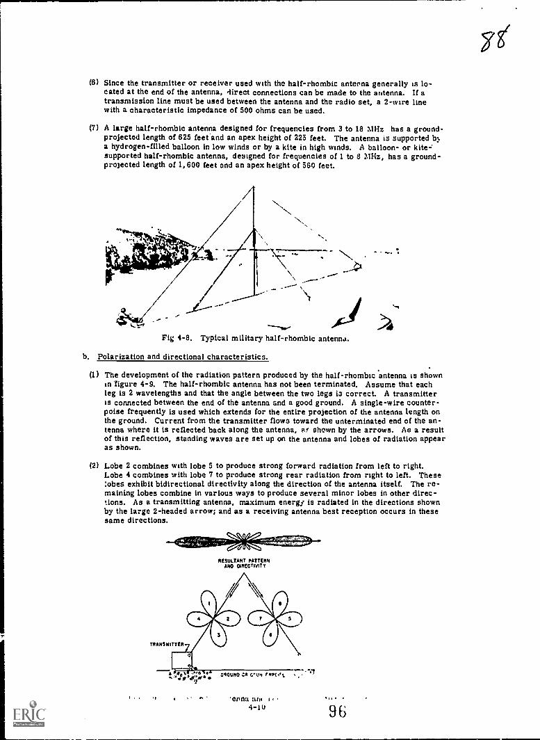
(6) Since the transmitter or receiver used with the half-rhombic antenna generally is lo-cated at the end of the antenna, direct connections can be made to the antenna. If atransmission line must be used between the antenna and the radio set, a 2-wire linewith a characteristic impedance of 500 ohms can be used.
(7) A large half-rhombic antenna designed for frequencies from 3 to 18 MHz has a ground-projected length of 625 feet and an apex height of 225 feet. The antenna is supported b2.a hydrogen-filled balloon in low winds or by a kite in high winds. A balloon- or kite:supported half-rhombic antenna, designed for frequencies of 1 to 8 MHz, has a ground-projected length of 1,600 feet and an apex height of 560 feet.
Fig 4-6. Typical military half-rhombic antenna.
b. Polarization and directional characteristics.
(1) The development of the radiation pattern produced by the half-rhombic antenna is shownin figure 4-9. The half-rhombic antenna has not been terminated. Assume that eachleg is 2 wavelengths and that the angle between the two legs is correct. A transmitteris connected between the end of the antenna and a good ground. A single-wire counter-poise frequently is used which extends for the entire projection of the antenna length onthe ground. Current from the transmitter flows toward the unterminated end of the an-tenna where it is reflected back along the antenna, Af shown by the arrows. As a resultof this reflection, standing waves are set up on the antenna and lobes of radiation appearas shown.
(2) Lobe 2 combines with lobe 5 to produce strong forward radiation from left to right.Lobe 4 combines with lobe 7 to produce strong rear radiation from right to left. Theselobes exhibit bidirectional directivity along the direction of the antenna itself. The re-maining lobes combine in various ways to produce several minor lobes in other direc-tions. As a transmitting antenna, maximum energy is radiated in the directions shownby the large 2-headed arrow; and as a receiving antenna best reception occurs in thesesame directions.
oelis.....:mm40007.VIOMP00"
RESULTANT PATTERNANO OtRECTMTY
.enna4-10 96
78`

(3) When a terminating resistor of about 500 ohms is connected between the far end of theantenna and ground (or counterpoise), conditions become different. Current from thetransmitter can flow only toward the resistor (fig 4-10). This resistor absorbs anyenergy that is not radiated, and, in so doing, prevents any reflection of energy backalong the antenna. As a result of t:sing the terminating resistcr Lobes 3, 4, 7, and 8disappear and only the forward lobes remain. Lobos 2 and 5 combine to produce in-tense radiation in the forward direction, from left to right, whereas lobes 1 and 6 pro-duce minor lobes. Consequently, when this half-rhombic antenna is used for trans-mission, it is unidirectional, and radiates maximum energy along the antenna in thedirection of the terminating resistor (fig 4-10).
(4) When the antenna is used for receiving, the antenna current will flow from the termi-nating resistor toward the feed point. Signals originating from the direction of the re-sistor will produce maximum effect on the receiver. Under these conditions, 311 arrowsin figure 4-10 would be shown reversed.
TRAN3MTTTER
---fEmmumma.---RESULTANT RADIATION
PATTERN
I i I V4444# GROUND OR COUNTERPOISEU
TERMINATINO
RESISTOR
A
Fig 4-10. Terminated half-rhombic antenna and resultant radiation pattern.
4-9. RHOMBIC ANTENNA
a. Description and operation. The highest development of the long-wire antenna is therhombic antenna (fig 4-11). It consists of :our conductors joined to form a rhombus, or diamond.All sides of the antenna have the same length and the opposite corner angles are equal. Incommon with previous nonresonant antennas, the rhombic antenna radiates best in the directionof the terminating resistor and receives best from the direction of the resistor. Maximumradiation does not occur in the same direction as the plane of the antenna, that is, horizontally.Instead, it occurs at some vertical angle above the horizontal plane, as shown by the wave angle,W. The title angle, T, is one-half the angle between the two legs making up one side of theantenna.
4-11
9 7
gel

TERMNATINORESISTOR
TOP VIEW
Fig 4-11. Basic rhombic antenna.
Figure '.-12 shows the individual radiation patterns produced by the four legs of the rhombicantenna and the resultant radiation pattern. If the tilt angle, T, is properly chosen for thelength of the legs used, the shaded lobes all add together to form an intense forward lobe in thedirection of the terminating resistor. Since the greatest percentage of rhombic antennas areused at high frequencies where the lengths of the legs are several hundred feet, most rhombicsare horizontal. Therefore, the horizontal polarization is most common.
INDIVIDUAL RADIATIONPATTERNS
A
RESULTANT RADIATIONPATTERN
Fig 4-12. Formation of the rhombic radiation pattern.
(1) Advantages. The rhombic antenna is used widely for long-distance high-frequency trans-mission and reception, for reasons explained below. It is one of the most common fixaci-station antennas, being very useful in point-to-point work.
(a) The rhombic antenna is useftil over a wide frequency range, a range of 2 to 1 beingcovered easily with excellent results. Although it is true that some changes in gain,directivity, and characteristic impedance do occur with change in operating frequency,these changes are small enough to be neglectrA. It frequency range of 4 to 1 can becovered by a typical rhombic antenna with 5c,, re3.4lts, ane st:Mard military rherr'-..3cover a frequency range ,Jf 5 to 1 or 6 to ' :::,104ort11,
4-129Er

q/1(b) Another advantage of the rhombic antenna is that it is much easier to construct andmaintain than other antennas of comparable gain and directivity. Only four supportingpoles of common heights from 50 to 75 feet are needed for the antenna, which has asimple form, being made up of four straight lengths of wire.
(c) The rhombic antenna also has the advantage of being noncritical so far as operation andadjustment are concerned. This follows from the broad frequency characteristics ofthe antenna.
(d) Still another advantage is that the voltages present on the antenna are much lower thanthose that would be produced by the same imput power on a resonant antenna. This isparticularly important when high transmitter powers are used or when high-altitudeoperation is required. The lower voltages mean less possibility of corona loss.
(2) Disadvantages.
(a) The rhombic antenna is not without its disadvantages. Probably the principal one isthat a fairly large antenna site is required for its erection. Each leg is made at least1 or 2 wavelengths at the lowest operating frequency, and when increased gain and di-rectivity are required, legs of from 8 to 12 wavelengths are used. Such requirementsmean that high-frequency rhombic antennas have leg lengths of several hundred feet,and so they can be used only when a large plot of land is available.
(b) Another disadvantage is that the horizontal and vtrtical patterns depend on each other.If a rhombic antenna is made to have a narrow horizontal beam, the beam is also lowerin the vertical direction. Therefore, it is impossible to obtain high vertical angle ra-diation except with a very broad horizontal pattern and low gain. Rhombic antennas areused, however, for long-distance sky wave coverage at ti.e high frequencies. Underthese conditions, low vertical angles of radiation (less than 20°) are desirable. Withthe rhombic antenna, a considerable amount of the input power is dissipated uselesslyin the terminating resistor. However, this resistor is required in order to make theantenna unidirectional, and the great gain of the antenna more than makes up for thisloss. .
b. Standard designs.
(1) Many rhombic antennas used for military applications are based on certain standardizeddimensions which make satisfactory operation possible over a frequency range of from4 to 22 MHz. This range includes the frequencies that commonly are used for long-distance point-to-point sky wave communication between fixed stations.
(2) The seven standard sizes used are designated as rhombic antennas A through G, inclu-sive (fig 4-13). Antenna A is the largest rhombi; and it is used when communicationis required between points over 3,000 miles apart. The leg of this antenna is about 11
wavelengths at the lowest operating frequency (4 MHz) and about 81 wavelengths at thehighest operating frequency (22 MHz). Antenna G, the smallest rhombic, is used whencommunication is required between points that are from 200 to 400 miles apart. Theleg of this antenna is somewhat less than 1 wavelength at the lowest operating frequencyand about 5 wavelengths at the highest operating frequency. Rhombic antennas B throughF inclusive have intermediate ranges and leg lengths.
(3)
*try,
Complete kits are available, which include all necessary material for the constructionof standard military rhombic antennas. The four large poles or metal supports usedare designated as side poles, front pole, and rear pole in the isometric view of rhom-bic antenna (fig 4-13). Terminating resiutors (or a dissipation line) are connected atthe corner of the antenna supported by the front pole. The transmission line which con-nects the transmitter or receiver to the antenna is attached to the corner supported bythe rear pole. As shown in the plan view, the side poles and the front pole are loc.ated3 feet from the corners of the antenna which they support, and the rear pole is located8 inches from the corner which it supports. These distances permit the installation ofstrain insulators and supporting harnesses which attach the antenna to the poles.
4-13
9 9

TRANSMISSIONLINE TO
TRANSINTTEROR
RECEIVER
REARPOLE
SIDEPOLE
TERMINATINGRESISTORS-I
FRONTPOLE
SIDEPOLE
MOMETMCVIZW
SIDEPOLE
oREARPOLE
SIDEPOLE
PLAN VIEW
FRONTPOLE
Fig 4-13. Standard military rhombic antennas.
(4) The guide given below indicates the essential dimensions used in the seven standardrhombic antennas, along with the useful ranges of these antennas. The various lettersdesignate dimensions that are indicated in the plan view of figure 4-13. All linear di-mensions az e given in feet. L refers to the leg length measured from corner to corner.This includes the length of the strain insulators used at the front and rear poles. T re-fers to the size of the tilt angle in degrees, as previously defined. H is the averageheight of the antenna above average ground level. The harness which ties the antennacorners to the poles usually is attached to the poles at a height 1 to 2 feet above H. Wis the pole spacing along the minor axis of the antenna. X is the distance between therear pole and the point at which the axes cross as measured along the major axis, andY is the distance between the front pole and the point at which the axes cross as meas-ured along the major axis.
TypeRange L(miles) (feet)
A 3,000+ 375B 2,000-3,000 350C 1,500-2,000 315D 1,000-1,500 290E 600-1,000 270F 400-600 245C 200-400 225
4-14
T(degrees)
H(feet)
W(feet)
X(feet)
Y(feet)
70 65 262.4 352.7 35570 60 245.6 329.5 331.870 57 221.6 296.7 29967.5 55 228 268.7 27165 53 234 245.4 247.762.3 51 232 219 221.360 50 231 195.7 198
1 u 0
V-
Section II. INSTALLATION
4-10. SITE SELECTION
a, Terrain requirements. The choice of an antenna site will depend on the nature of the localand intervening terrain and the tactica situation. Planning should always be preceded by a care-ful study of terrain maps and, whenever possible, by reconnaissance, in order to obtain detailedinformation concerning the availability, accessibility, and size of desirable sites.
(1) Amilabi.h...q Several tentative locations should be proposed. rJr temporary locations,consider the length of time the site will be used. Permanent sites should be carefullycoordinated with adjacent units to prevent future building programs from rendering thesite unsuitable for use.
(2) Accessibility. Any fixed radio station utilizing high power equipment and large an-tennihs must have access to a good road system to permit movement of equipment andsupplies. It should be close to existing or planned utilities such as power and water.
(3) Size. The area selected must be large enough for the installation of necessary buildings,as well as the antennas. Also, space must be provided to allow sufficient separationof transmitting and receiving antennas.
b. Technical factors. Factors to be considered will depend on the type of equipment used and
the tactical situation.
(1) Location. A radio station must be located in a position that will assure communicationwith all other stations with which it is to operate. To obtain efficient transmission andreception, the following factors should be considered:
(a) Hills and mountains between stations normally limit the range of radio sets. In
mountainous or hilly terrain, positions relatively high on the slopes (fig 4-14) shouldbe selected. Locations at the base of a cliff or in a deep ravine or valley (fig 4-14)should be avoided. For operation at frequencies above 30 MHz, a location that willgive line-of-sight communication should be selected whenever possible.
(b) Dry ground has high resistance and limits the range of the radio set. If possible,the station should be located near moist ground, which has much less resistance.Water, and in particular salt water, will greatly increase the distances that canbe covered.
(c) Trees with heavy foliage absorb radio waves, and leafy trees have a more adverseeffect than evergreens. The antenna should be kept clear of all foliage and densebrush.
(2) Man-made obstructions.
(a) A position in a tunnel or beneath an underpass or steel bridge (fig 4-14) should not beselected. Transmission and reception under these conditions are almost impossiblebecause of high absorption of RF waves.
(b) Buildings located between radio stations, particularly steel and reinforced concretestructures, hinder transmission and reception.
(c) All types of pole wire lines, such as telephone, telegraph, and high-tension power-lines, should be avoided in selecting a site for a radio station. Such wire linesabsorb power from radiating antennas located in their vicinity. They also introducehum and noise interference in receiving antennas.
4-15
l 01
93

(d) Positions adjacent to heavily traveled roads and highways should be avoided. Inaddition to the noise and confusion caused by tanks and trucks, ignition systems inthese vehicles may cause electrical interference.
(e) Battery-charging units and generators should not be located clossto the radio station.
(1) Radio stations should not be located close to each other.
(g) Radio stations shoud be located in relatively quiet areas. Copying weak signalsrequires great concentration by the operator, and his attention should not be divertedby extraneous noises.
(3) Local command requirements. Radio stations should be located some distance fromthe unit headquarters or command post that they serve. Thus, long-range enemy artilleryfire, missiles, or aerial bombardment, directed at the stations as a result of enemydirection finding, will not strike the command post area.
(4) Cover and concealment. The locations selected should provide the best cover and con-cealment possible, consistent with good transmission and reception. Perfect cover andconcealment may impair transmission and reception. The amount of permissibleimpairment depends on the range required, the power of the tranamitter, the sensitivityof the receiver, the efficiency of the antenna system, and the nature of the terrain. Whena set is being used to communicate over a distance that is well under the maximum range,some sacrifice of communication efficiency can be made to permit better concealmentof the set from enemy observation.
(5) Practical considerations.
(a) Pack seta have sufficiently long cordage to permit operation from cover, while the radioset is below the surface of the surrounding terrain and the antenna is in the clear.
(3) Some sets can be controlled remotely from distances of 100 feet or more. Sets of thistype can be set up in a relatively exposed position, while the operator remains concealed,
(c) Antennas of all radio sets must extend above the surface of the ground to permitnormal communications.
(d) Small tactical set antennas are usually of the whip type. These antennas are difficultto see from a distance, especially if they are not silhouetted against the sky.
(e) Open crests of hills end mountains must be avoided. A slightly defiladed positionjust behind the crest gives better concealment and sometimes provides better transmisswn.
(f) AU permanent and semipermanent positions should be properly camouflaged forprotection against both aerial and ground observation. However, the antenna shouldnot touch trees, brush, or camouflage material.
(6) Local communications. Contact must be maintained between the radio set and themessage center at all times, either by local messenger or field telephone. The stationshould also be readily accessible to the unit commander and his staff.
(7) Final considerations. It is almost impossible to select a site that will satisfy all technicaland tactical requirements for a radio set. Therefore, a compromise is usually necessary,and the best site available is selected. It is also a good idea to select both a primaryand an alternate site. Then, if radio communication cannot be established at the primarylocation, the set can be moved a short distance to the alternate position.
102
4 - 16

OVERHEAD STEEL BRIDGES UNDERPASSES
.f. .1/44.
404.
Tl
ON LEVEL GROUND
Fig 4-14. Siting.
4-17
103
HIGH HILL

c16
4-11. SAFETY PRECAUTIONS
During installation and use of vehicular-whip and other antennas, field masts, towers, andmetal poles, accidents have occurred which resulted in damage to equipment, serious injury, andDEATH due to the failure of personnel to observe safety precautions. The installation or use ofsuch assemblies is not always limited to placing the equipment in operation, but in some instancesthe primary purpose is field demonstrations, training of riggers or linemen, and similar endeavors.Prior to installing or erecting any equipment, the area must be carefully surveyed for locationof powerlines, their height above ground level, and proximity to the installation site. In addition,overhead obstructions that may be encountered when mobile operations are contemplated shouldbe considered. When an installation in the vicinity of powerlines is planned, the responsibleauthority will warn all who are to participate in the exercise that contact of the structure withhigh-tension powerlines in the course of erection can--and has--caused instant death. A
,WARNING to this effect should precede the order to begin erection. The technical mi.nualrelating to the equipment should be thoroughly read before attempting any installation or erection.The CAUTION and WARNING notices are placed in these manuals for the protection of personnel,and must be observed. Safety precautions to be followed in order to prevent serious injury orfatality are outlined below.
a. Whip antennas (fig 4-15).
(1) Never lean against or grasp a whip antenna when a transmitter is operating. Severeburns may result.
(2) When operating with vehicular equipment, never pass under powerlines if you have anydoubt about adequate overhead clearance between the lines and the antenna.
(3) When mobile operation Ls mandatory, insure that the height of the antenna from the groundmeets local requirements as prescribed. In any event, make certain that the antennawill clear known overhead obstructions and powerlines.
(4) Never permit arms or legs to extedd over the sides of a vehicle. If the antenna contactsa powerline, the body will act as an electrical conductor upon contact with the ground,wet bushes, trees, or other foliage. Serious shock or DEATH may result.
(5) Never dismount from a vehicle unless certain that the whip antenna is not in contactwith powerlines. A vehicle is normally insulated from the ground, and personnel arerelatively safe while inside the vehicle. However, if the antenna is in contact withpowerlines, an individual in contact with both the ground and the vehicle is groundedelectrically (fig 4-15), and fatal shock may result.
4-18
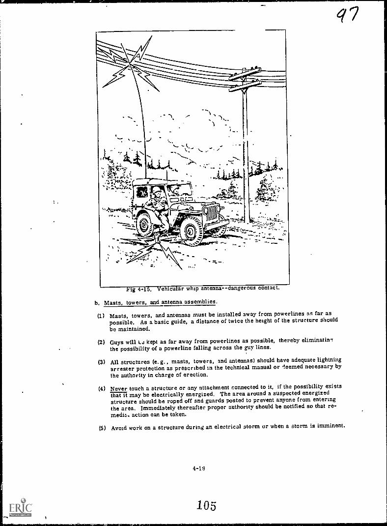
q 7
.Fig 4-15. Vehicular whip antenna--dangerous contact.
b. Masts, towers, and antenna assemblies.
(1) Masts, towers, and antennas must be installed away from powerlines as far aspossible. As a basic guide, a distance of twice the height of the structure shouldbe maintained.
(2) Guys will L4 kept as far away from powerlines as possible, thereby eliminatinlthe possibility of a powerline falling across the guy lines.
(3) All structures (e. g. , masts, towers, and antennas) should have adequate lightningarrester protection as prescribed in the technical manual or leemed necessary bythe authority in charge of erection.
(4) Never touch a structure or any attachment connected to it, if the possibility existsthat it may be electrically energized. The area around a suspected energizedstructure should be roped off and guards posted to prevent anyone from enteringthe area. Immediately thereafter proper authority should be notified so that re-medit.. action can be taken.
(5) Avoid work on a structure during an electrical storm or when a storm is imminent.
4-19
105i

(6) All ropes and guys will be inspected for worn spots, frays, rotten portions, andother imperfections, prior to being placed in use. Ropes or guys that show suchimperfections should not be used.
(7) Never attempt to support a structure, using fewer guys than prescribed in the tech--Eaamanual.
(a) All temporary guys shall be left in place until permanent guys have been installed.
(9) In erecting a structure such as Mast AB-301-G, normal procedure requires thatthe side guy lines be attached and anchored in position prior to erection. Whenerection is accomplished, misalinement of these guys can cause them to over-tighten and buckle the structure. Close observation of the side guys during erectionshould be maintained to prevent overtightening.
(10) Guy lines must be properly attached and controlled to prevent the structure frorrpassing over its upright position (900). Failure to control the erection in thismanner may cause the structure to fall over the men pulling it erect.
(11) When hoisting objects by means of ropes, personnel should stand clear of th e. hoisur;area.
(12) Do not fasten guy lines over sharp-edged surfaces which may abrade or cut them,unless absolutely necessary, and then only after protective padding has been plactiover the sharp edges.
(13) Only personnel required for the erection of a structure will be in the erection area.
(14) All anchors must be securely entrenched in the ground. In marshy or sandy terrain,special provisions must be made to obtain required anchor-holding strength.
(15) When selecting anelor locations for guys, sivoid locations that will cause the linesto pass over roadways. When roadways cannot be avoided, maximum overheadclearance must be maintained. Guy lines over roadways will be plainly markedwith warning flags tied in strips to the guys. Warning signs indicating the heightof the overhead obstructions will be posted.
(18) If in the course of installation it becomes necessary to suspend operations, do nutdo so until sufficient guys are attached to safely support the structure.
(17) Ropes, davits, and guys must be of sufficient strength to provide adequate support.
(18) When work aloft is necessary, avoid unnecessary climbing or movement on thestructure.
(19) Personnel engaged in the installation of a structure should be adequately instructcuin the overall method of erection.
(20) Erection of a structure should be accomplished with trained personnel in arrot danc.Pwith the applicable technical manual. To do otherwise may result in serious injuryto personnel or damage to equipment.
(21) Specific safety devices such as safety belts, rubber gloves, safety shoes, etc. ,
shall be used for the protection of personnel, when provided. The few secondssaved by not using these devices does not compensate for the hazards involved.
(22) It is not feasible to mention every type of equipment and every hazard which maybe encountered. Nevertheless, CAUTION and commonsense must be exercised atall times. The precautions listed here are of a general nature, and can be appliedin general to all types of equipment.
4-12. GROUNDS AND COUNTERPOISES
When the grounded type of antenna is used, it is important that the ground has the lea,tpossible amount of resistance This is?. nortis.cary to minsmirt: izrowid .andgood reflecting surface for energy rachated (lownli,ard from the ontenna Me pioblem lb. IltrA
to make a ground connection with the Vin y immu rn of resist int 0
4-20 106

qga. Ground roil. The most common type of ground connection is the ground rod. These are
mad. oTWarlized iron, steel, or copper-plated steel in various lengths. Generally, one endis pointed so it may be driven into the earth easily, while the other end is fitted with a clamp toattach the ground lead. A good ground connection can be made by using several ground rodsconnected in parallel and spaced 6 to 10 feet apart.
b. Counterpoise, when a ground rod cannot be used because of high resistance in the soil,a counterpoise may be used. The counterpoiae is used to electrically raise the ground for usein transmitting radio waves. The counterpoise has a geometrical form (fig 4-16), is constructed
Fig 4-16. Typical counterpoises.
of wirc and erected a short distance above the ground. It is also insulated from ground. Thesize of the counterpoise is not critical, but is generally larger than the antenna. The counter-poise should extend equal lengths at all angles from the antenna. Short Jumpers between theconductors prevent absorption of RF energy.
c. Methods of reducing ground resistance. When an antenna must be erected over soilhaving a high resistance, it is good practice to treat the soil to reduce this resistance. Severalsubstances can be used. Listed in order of preference, they are: sodium chloride (salt), cal-cium chloride, copper sulfate (blue vitriol), magnesium sulfate (Epsom salt), and potassiumnitrate (saltpeter). rhe type of soil and its moisture content determine the required amountof treatment.
4-13. ORIENTATION
a. Radiation. The long-wire V, half- and MB-rhombic, and array antennas produce aradiation pattern that composes a relatively narrow beam. For maximum performance andefficiency, they require accurate orientation. Best results are obtained when the antennais oriented in the horizontal-short path direction to the distant station, except in the case oflong-range transmission for which the antenna should be oriented by use of the great-circle
; bearing to the distant station.
b. Position and bearing. To orient the antenna correctly, the exact position and bearingof each radio station must be known. All that is needed is a map, protractor, and compass.Proceed in the following manner:
(1) From the map determine the magnetic bearing of the distant station, using the protractor.Be sure to add or subtract the correction factor from grid north, to obtain the correctmagnetic bearing.
(2) At the antenna location, uaing the compass, sight and plot the magnetic bearing to the
distant station.
(3) Erect the antenna so that maximum radiation occurs in the same direction as the plottedmagnetic bearing to the distant station.
Figure 4-17 illustrates the orientation of two terminated full-rhombic antennas.The antennas and radiation pattern are drawn oversized for clarity, --Assume thesite to be in the upper right-hand corner of the map.
(a) nraw a line between the proposed sites. Line up the protractor with one of the north-south grid lines. Measure the angle between it and the line drawn between proposedsites. This is 400. Next, add this to 1800, for a grad azimuth of 2200. Now subtract5.5° to determine the magnetic bearing-214.50.
(b) At the antenna location, using the compass, sight and plot a bearing of 213.50.
(c) Erect the antennas so that maximum radiation will occur along the bearing of 214.50.In the case of the terminated full-rhombic, maximum radiation bisects the antenna inthe direction of termination.
4-21

00.:1 'k r-,,-,1"-
*Orcier
: ,344' 7 I41irirrb,' 4,'Op\ 410/....?
1"..'LIM az, ,
"4,,N-
40.:E
4
,4-.-4; "-=---.:--- 44_---
Altrup" ulli.
1 1
4 J
(4,t". e
110Y
!I.; ,
liricF . ,
44,
siZr ki
,r irr4---v,-4k.Orsak%,
. r r --- `..4:: iot -r.- -11,... *1447',,_ 1, -
-;'-c2f4.: kk--.1, : "/1..:hAlf,:=P4--
14.'Zi; ; ; ...... s,'I \rir'';:.'n 4 11,2 ,,, .,..it.i , *-,i.'&r:=,,---,,,"---6.4
... .
4 ew...
, ...vit..,Nrkit%; \ \ a ___-.,,,... 114V. . Ay.At-'44,".r1;.., "'s ...- ...do:-".,,1 7.2,4S3 k,...*AM;r4i1r. -*". 74r,I.
"7'. r ZfeeeN.... '-:e4 . - - -4 /I .4,; fili 4 ....4,...,,Atg; . ,...-_,...... 4,...1.1,..-.. -....
i, .411 , {
de i 4 ' /"..'.;.. 4'\.1...t...' 1..,.
Trig'. ,,*7tf 1,
s.,S
ofA
011,..7.410.1":41to,
,
.1 .Ar. e
_30,
s"
;or ,ter - lp 3.1".,.pasl
tft'-V91
- As\,10. :
'4,*det p-so*dr>1/4 of '
)14(OM - Wit1,1i)1f1/04 "ist
, ,tAV A
IPf
Af°&. "
rPi0,4",
914
rrN:tt wkc,i-r>
ri4gc
9%A.
T
tV(tk,c1/4,4'A1.
hir4` A, JA*134
t ,11. 7 ev
--tr%
41
-
\V.x\16..7. ' !, -,
1
NoTaiirAttau

* ki,i144
.

ito 4P--
4-14. PROFILES
a. Line of sight. Since vhf radio waves tend to travel In straight lines, the radio stationsshould be located so that linc-ofsight transmission can be used.
b. Distance. The curvature of the earth limits the distance over which line-of-sight trans-mission may be %lead. To detcrmine the maximum distance between two radio stations with theintervening terrain at sea level, the following formula is used.
I) . 4hlit' 4 figrD Is the distance in miles; Ht the height of the transmitting antenna in feet, and Hr the heightof the receiving antenna in feet.
For example, with both antennas 50 (eet above sea level. the maximum distance that canbe covered before the line-of-sigh :. would be obstructed by the curvature of the earth is 20 miles.When the intervening terrain is not at sea level, a profile map should be used to see if a line-of-sight path exists.
(1) By plotting the profiles or contours of the map on a graph, it is possible to visuallydetermine If a line-of-sight transmission path exists. Since profile graph paper is oftennot accessible, we will consider only profiles plotted on any linear graph paper and thencorrected for the curvature of the earth. The procedure for plotting the profile is asfollows:
(a) Determine from the terrain map (fig 4-113) the scales to be used for distance andelevation.
Scale: 2. 5 inches x 1 mile Contour interval x 20 feet
Fig 4-18, ,Terrain map showing two transmission paths.
4-211 0

Pl.:, 4.8. (.contlimed)

/ 4(b) Draw a line on the terrain map between the proposed sites (paths 1 and 2). Measure
these lines and convert them to distance (4.3 miles for path 1 and 5.1 miles for path 2).
(c) Using path 1 as an example, determine the elevation at each site. Hill 735 with a 40-footantenna has a toto elevation of 775 feet. This point is marked on the vertical scale ofthe graph (fig 4-1 9) above 0 mile. Hill 914 with a 40-foot antenna brings its total elevationto 954 feet. This point is plotted on the vertical scale above 4. 3 miles, since that isthe distance between the two stations. Every 20 lines on the horizontal axis represents1 mile of distance, and every line on the vertical axis represents 20 feet of elevation,
(d) Draw a dashed line between these two points to denote the apparent line-of-sight.
(e) Inspect the terrain map, noting all high- and low-altitude points. Plot all these pointson the graph paper and join them with a dashed line.
(f) Correction must be made for the earth's curvature to determine a true line-of-sightpicture. A high or low point is selected which is as near to the halfway point as possible.(See point A, fig 4-1 9. ) By means of the figures shown in the table below, the elevationof all prominent points in both directions from the central point must be corrected.Table 4-1 shows the corrected elevation to be 3 feet at a distance of 2 miles from thecentral point.
Table 4-1. Elevation Correction Factors
Conversion to sea level elevationsto line-of-sight elevations
Conversion to sea level elevationsto line-of-sight elevations
D(Miles from ref-erence point)
Elevation correc-tion (ft)
D(Miles from ref-erence point)
Elevation correc-tion (ft)
2 3 22 324
4 11 24 3846 24 26 455
8 43 28 520
10 67 30 600
12 96 32 680
14 130 34 770
16 170 36 862
18 21720 266
The new plots are connected by a solid line curve and a straight line is drawn to the correctedsites. This line represents the true line-of-sight.
(2) As indicated by a profile (fig 4-19), path 1 is obstructed and would not be a good line-of-sight transmission path.
4-27
112

11111 1111111111111MiliiiiiiiiiiiiiiiiiiIIIIIIIII 11111MIllinME:Hill 1111111 III 111111111111 .; 1 IIIIIMMIIIIP IIIIIIIIIIIIIMMI
Eh MEE II 111111111111111111011111111151E1111111111111111111111111
III EN iiti 1111 !!1111111111111111111111111111111111hili IMF LIMPID]
Ill !' h 1111 1111111111111111111 . IIIIIIIIIIIIIII It.- Rill ui-iNEONMINIM MEIN REHM! "MEM llEMIIIIIMIEftft ME rill 1111111111 INEMILIMENIE IN
I is .tilmmum gp. 111110101091MEMINI711[1111, 111111. Mil.1,....i.glilliiiiiiiiiiiiiitilliii11111111111211 IIIIII
.__-Li-it
II 1110 rirailiiihME titi ill NUM
ilia id NM alitigirt, iiiiiiiillEitT ill111ii MI IIIIII IIIMILailluRIO
.111112,22fideirallE11111111.1: iili ii;: 111111111:4--'. IM,II 1111 MIMEO "r-thi;111 itii 111111111 M
111
I II EOM 1 i 1 11 1111111111111111
t!! Hill Hifi 111111111111111111111111r11 ME IIIII, MEE ;III Mil illi I111111111111111WE
i:,14
t;
:iii L.:IIILI!,Il
I

1200
1000
800
600
400
200
11111111111110MMIIIIIIIIIIIIIIIIIIIIMMEMEN11111011111111111111
11111MOMMIIIIMI11101011111100 100110E11111 11111111111111111111 ffil MINI
II!! HINIIIMU !I : 1111111111iffill1111 111111110 Milt , Dill Milli1111110011111EMOIMEN11111 1 : it H IIIIIIIIIIIIII
ill 11111IF ', 1111011111111111011110GISEMINI1 III ' 11 1 III MI IIIMIETBSIE , Ilii1111111111111111 1 11111111: 'filallEMIN II
filliiiiiiERINERM100101111111T MI 1111111111111111111111
111111=INCIMM11110-Vinilligi.... IIIIIIIIII
!44.
II i
4-,4II! E M MN MEMEImi, NMPM1 MN ME EOM' MU
it,fp,
+
LH
.. 4 mit:" I. F-1111 MEW A4 1111111411111111111111* f r
II 1:JrMINIME11111110r OBEN "Ill
MI NINW I t"' III Err 1 El IIIIII IMO UM III
11OEM IIIIIIIIII 1111111101111111111111 111111111111 , IIIIIIIIIMME1111111111101101111111111111 111111 ffi ' 1'1 Mr!:
11111 pm 11;1 iii!EN IN4 ,
, 1 .
i1t,
/ 0
..

(4) As can be seen, the amount of corrected elevation increases as the distance from thecentral reference point increases because of the curvature of the earth.
4-15. FIELD EXPEDTENT METHODS
a. Introduction. Antennas are sometimes broken or damaged, thereby causing failure orpoor communications. If a spare is available, the damaged antenna can be replaced. When thereis no spare, it may be necessary to make or construct an emergency antenna. The following con-siderations will aid in the construction of an emergency antenna.
(1) Copper or aluminum is the best wire for antennas. In emergencies, any type may beused.
(2) The exact length of many antennas is critical. For this reason, the length of theemergency anterina should be the same as that of the antenna it replaces.
(3) Antennas supported by trees can usually survive heavy windstorms if a stout branchor trunk is used as the support. A little slack should be provided in the guysto prevent breaking or stretching as the tree sways.
(4) Guys used to hold antenna supports should be made of rope or wire.
(5) Wire guys may affect the operation of the antenna unless cut into several short lengthsand fastened together with insulators. Lead weights of approximately 5 oz attachedto the slack guys will maintain a constant tension on the antenna and prevent it fromswaying.
(6) The height at which an antenna is placed above ground will have an effect upon itsoperation. The antenna height should be changed until the best performance is gained.
(7) If a whip antenna is broken, the twosections can be connected as shownin figure 4-21A. Figure 4-21B showsa method of repair when one of thesections is lost or unusable. Add apiece of wire that is nearly the samein length as the missing section torestore the antenna to its originallength. Next, 41ean the two sectionsthoroughly to insure good electricalconnections. If possible, solder theconnections. Then lash the polesupport securely to both sections ofthe antenna.
4-30
POLE OR*RANCH
I
LASHING 1ELECTMCAL *
CONNECTIONS
q;1o71
oII
L
il - ANTENNA HIRE
1 POLE
I
!liiT ELECTRICAL
CONNECTIONS
bi-p LASHING
Pt1
8
Fig 4-21. Whip antenna repair%
11 0

(8) Usually insulators are made of glassor porcelain. If an insulator breaksand a spare is not available, glass,rubber, or dry wood can be insertedin its place. Figure 4-22 shows twotypes of improvised woodeninsulators--for emergency use only.
411111111114111103,41111111111r
.......11111111r
Fig 4-22. Improvised wooden insulators.
b. Vertical antennas. A vertical antenna may consist of a piece of wire supported by a treeor wooden pole (fig 4-23A). If the mast is not long enough to support the antenna, the connectionat the top of the antenna may be modified (as in fig 4-23B) to form an inverted-L antenna.Figures 4-23C and D show additional methods of supporting vertical antennas.
A
.........INsysATORS
r*1
WOOOEN ANTENNAMAST WINE
INSULATON
SAINOSZT
GROUNO STANEPIPE
Fig 4-23. Improvised vertical antennas.
4-31
11 6
it

c. Half-wave antennas. An improvised antenna of this type can be constructed with wireand rope as shown in figure 4-24. An insulator is placed at the exact center of the antenna. A2-wire transmission line is used, with one wire connected to one side of the antenna and thesecond wire connected to the other side. Antenna length is important; therefore, the twr wiresshould be cut as closely as possible to the correct length.
INSULATORS
WAYC TN MAVIS %AWN
ISSIONLINC
Fig 4-24. Improvised half-wave antenna.
(1) Short half-wave antennas can be supported by uprights of wood, as in figure 4-25. Ahorizontal half-wave antenna is illustrated in figure 4-25A. A vertical antenna of thistype is shown in figure 4-25B. These antennas can be turned in any position for maxi-mum efficiency.
INSMA1011...{WATS WWII
tIONAATOR
INVIt UNTO
INSULATON
TRANSMISSIONUNC
A
Fig 4-25. Improvised vertical and horizontal half-wave antennas.
(2) Another method for constructing a short half-wave antenna is pictured in figure 4-26.The ends of this antenna are connected to a length of dry wood such as bamboo. Thebend in the pole holds the antenna straight. The mast is made of a pole or bundle ofpoles.
4-32
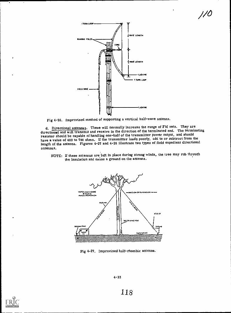
!TURN LOOP
BAMBOO POLLS
FIELD PAL
z Welt LINOTH
7 *we LLNSTH
L AVMS
I TIAN LOOP
LASMINS
Fig 4-26. Improvised method of supporting a vertical half-wave antenna.
d. Directional antennas. These will normally increase the range of FM sets. They aredirectional and will transmit and receive in the direction of the terminated end. The terminatingresistor should be capable of handling one-half of the transmitter power output, and shouldhave a value of 400 to 700 ohms. U the transmitter loads poorly, add to or subtract from thelength of the antenna. Figures 4-27 and 4-28 illustrate two types of field expedient directionalantennas.
NOTE: If these antennas are left in place during strong winds, the tree may rub throughthe insulation and caiise a ground on the antenna.
Fig 4-27. Improvised half-rhombic antenna.
4-33
118

/II
Way' mityloaTOM ue
vlot1CAAVOlAntAtiC.1
1111%101
Fig 4-28. Improvised wave antenna.
e. Ground plane antenna. The AN/PRC-25 antenna can easily be modified to construct aground plane antenna (fig 4-29). By cutting three wires of the same length as the AT-271/PRCand strapping them to a 20- to 30-foot pole along with the AB-591 /PRC, the antenna caneasily be assembled. 'Use a 2-wire transmission line. One wire is connected to the AB-591 /PRCand wrapped around the outside of the radio set's auxiliary-antenna jack. The other wire isconnected to the AT-271 /PRC and inserted in the center of the auxiliary-antenna jack.
AT- 271/PRC
A13-591/PRC GROUND PLANE
GUY LINE
DISULATOR
/AUXANT.JACK
Fig 4-29. Ground plane antenna improvised by using the AN/PRC-25 antenna,
4-34
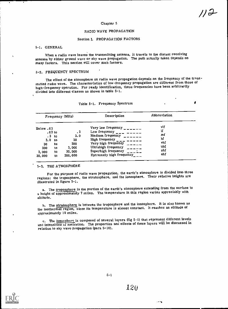
Chapter 5
RADIO WAVE PROPAGATION
Section I. PROPAGATION FACTORS
5-1. GENERAL
When a radio wave leaves the transmitting antenna, it travels to the distant receivingantenna by either ground wave or sky wave propagation. The path actually taken depends onmany factors. This section will cover such factors.
5-2. FREQUENCY SPECTRUM
The effect of the atmosphere on radio wave propagation depends on the frequency of the trans-mitted radio wave. The characteristics of low-frequency propagation are different from those ofhigh-frequency operation. For ready identification, these frequencies have been arbitrarilydivided into different classes as shown in table 5-1.
Table 5-1, Frequency Spectrum f
Frequency (MHz) Descr iption Abbreviation
Below . 03 Very low frequency vlf
.03 to .3 Low frequency If
. 3 to 3.0 Medium frequency mf3.0 to 30 High frequency hf
30 to 300 Very high frequency vhf
300 to 3,000 Ultrahigh frequency uhf
3,000 to 30,000 Superhigh frequency shf30,000 to 300,000 Extremely high frequency_ ehf
3-3. THE ATMOSPHERE
For the purpose of radio wave propagation, the earth's atmosphere is divided into threeregions: the troposphere, the stratosphere, and the ionosphere. Their relative heights areIllustrated in figure 5-1.
a. The troposphere is the portion of the earth's atmosphere extending from the surface to
a height of approximately 7 miles. The temperature in this region varies appreciably with
altitude.
b. The stratosphere is between the troposphere and the ionosphere. It is also known asthe isothermal region, since its temperature is almost constant. It reaches an altitude ofapproximately 18 miles.
c. The ionosohere is composed of several layers (fig 5-1) that represent different levelsand intensities of ionization. The properties and effects of these layers will be discussed inrelation to sky wave propagation (para 5-10).
5-1
120
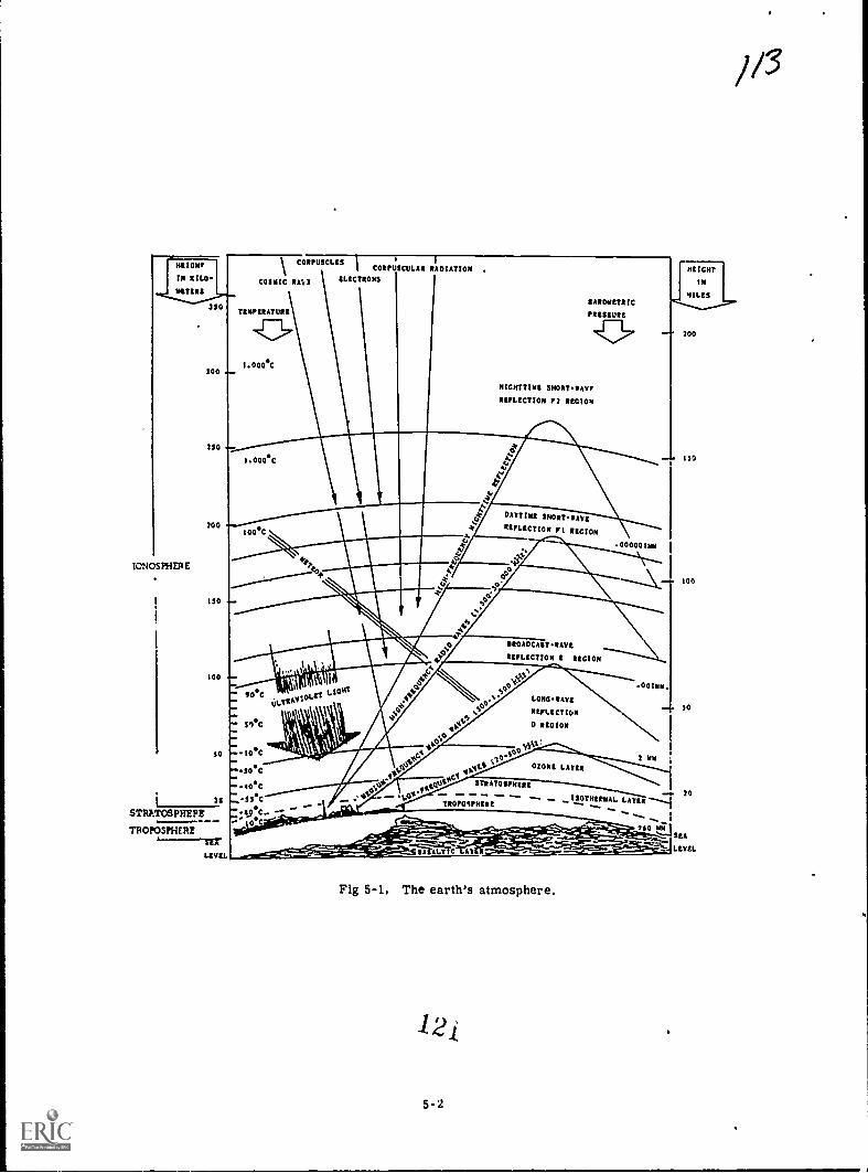
HEIM \ CORPUSCLESCOE OCULAR R
I:4
DIAT0 M .IN KILO. COSMIC RAI 2 ELECTRONS
WERE
IONOSPHER E
3 0
300
350
300
150
100
5
35
STRATOSPHEPZ
TROPOSPHERE
1.EVEL
tttttt Aim
1.000*C
I.000*C
&ARMEE IC
ttttt URI
NIGHTTIME SNORTVAT
REELECTION Pl 1E01014
100C
Sal
1.11111111L1:1
1 0*COLIEASSOLIT
LIONS
ASeC-.7.10*C
"*3 0*C
-*40*C
' 0
A.
Al\
DAYTIME SHIM...PAVE
ttttt CTION F 1 REGION
,943
40
4
160
. 0000011/1
SROADCAST.VAVE
OIFLECTION I REGION
1
LONO VASE
'moos t011
D REGION
2 NMOZONE LASER
1/3
STRATOSPHERE
TROPOSPHEREISOTHERMAL
."*"^".-":"'_
- -1Tt. AV
Fig 5-1. The earth's atmosphere.
5-2
760 1117
200
ISO
100
so
29
51A
LEVEL

/45-4. WAVE BENDING
A radio wave may travel to a distant receiving antenna in a straight line, or the wavepath may be altered through reflection, refraction, or diffraction.
a. Reflection. The reflection of a radio wave is identical to that of any other type wave.For example, when a ray of light falls on the surface of a mirror, nearly all of it is turnedback or reflected. The efficiency at which the reflection of radio waves occurs depends on thesurface of the reflecting material. Large, smooth metal surfaces of good electrical conductivity,such as copper, are very good reflectors. The earth's surface is also a good reflector.
Figure 5-2 shows a radio wave reflected from a smooth surface. (Remember that theongle of incidence always eo Als the angle of reflection.) However, the incident wave front,A-Al, is reversed by the reflecting surface and appears at B-Bl 1800 out of phase. The reasonis that point X of the incident wave reaches the reflecting surface before point Y. It is reflectedto point X1 during the time it takes point Y to move to the point of reflection, Yl. The parallelarrows indicate the phase reversal.
04.ecbtit Oh
CV fAngle ofIncidenc
A 1
PolarizationB1
OC eNNO.C% ,r4
CC' iN*NS cV4
Angle of Reflection
ReflectingSurface
1 1
Fig 5-2. Reflection of a radio wave.
b. Refraction. If a beam of light strikes a smooth surface such as water, part of the beam
will be reflected arid a portion will penetrate the water's surface. This penetration resultsin refraction. For example, if a spoon is immersed in a glass of water and viewed from anangle, it appears to be bent at the point where it enters the surface of the water. The reasonis that light waves travel faster through air than through water. Figure 5-3 illustrates thisphenomenon.
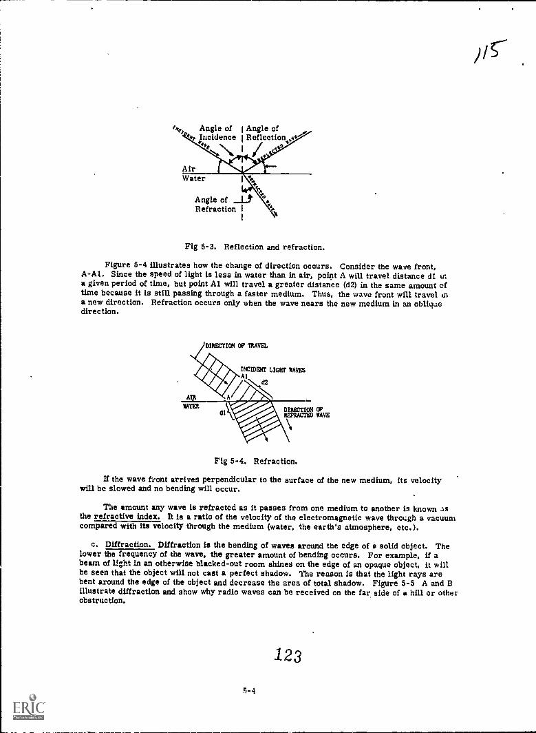
tke, Angle of I Angle oflop Incidence I Reflection iv"'
AirWater
Angle of _L.,Refraction 1
1
Fig 5-3. Reflection and refraction.
Figure 5-4 illustrates how the change of direction occurs. Consider the wave front,A-Al. Since the speed of light is less in water than in air, point A will travel distance di ina given period of time, but point Al will travel a greater distance (d2) in the same amount oftime because it is still passing through a faster medium. Thus, the wave front will travel ina new direction. Refraction occurs only when the wave nears the new medium in an obliquedirection.
DIRECTICN OP MUM
INCIDDTT LIGHT SAWSAl
d2
AIR
RATERDIRECTION CPREFRACTED NAVE
Fig 5-4. Refraction.
If the wave front arrives perpendicular to the surface of the new medium, its velocitywill be slowed and no bending will occur.
The amount any wave is refracted as it passes from one medium to another is known asthe refractive index. It is a ratio of the velocity of the electromagnetic wave through a vacuumcompared with its velocity through the medium (water, the earth's atmosphere, etc.).
c. Diffraction. Diffraction is the bending of waves around the edge of a solid object. Thelower the frequency of the wave, the greater amount of bending occurs. For example, if abeam of light in an otherwise blacked-out room shines on the edge of an opaque object, it willbe seen that the object will not cast a perfect shadow. The reason is that the light rays arebent around the edge of the object and decrease the area of total shadow. Figure 5-5 A and 13illustrate diffraction and show why radio waves can be received on the far side of a hill or otherobstruction.
123
5-4
Pc

11111111111111
J I I 1 1 1 1 1 1 1 i 1 1
N1014411QUISICV RANO WAVES
LOW.TREQUINCY ItADIO WAVES
Fig 5-5. Diffraction of high- and low-frequency radio waves.
Section U. GROUND WAVE PROPAGATION
5-5. GENERAL
This type of propagation does not make use of reflections from the ionosphere. The fieldintensity of the ground wave depends on these factors, characteristics of transmitting the radiowave, its diffraction around the earth's curvature, electrical properties of the terrain, natureof the transmiasion path, and climatic conditions.
Since the earth acts as a semiconductor, some of the radiated energy is absorbed anddissipated in the form of heat. Thus, ground wave transmission is limited to moderate-distancecommunications (up to several hundred miles) due to the inherent losses. There are some ex-ceptions at low frequencies and special high-frequency applications.
5-6. COMPOSITION
Figure 5-6 shows the paths taken by the ground wave in its travel. It may be conductedby the earth's surface, refracted in the troposphere, take a direct route, or be reflected.Thus the ground wave is considered to be made up of the following: direct wave, ground-reflectedwave, surface wave, and tropospheric wave.
5-5
124
//6

Tropospheric Path
Direct Path
aceted
Transmitter Receiver
fruAFig 5-6. Ground wave paths.
a. Direct wave. This component of the wave travels straight from the transmitting bntennato the receiving antenna. It is limited only by the line of sight frcm the transmitter plus thesmall distance added by atmospheric diffraction of the wave around the curvature of the earth.It is also subject to refraction in the troposphere, but is not affected by the earth's surface.
b. Ground-reflected wave. This component reaches the receiver after being reflected.Upon reflection it has a phase reversal of 1800.
Figure 5-7 illustrates a comparison between the reflected and the direct wave, with thetwo waves in phase up to the point of reflection. After reflection, they are 1800 out of phase,plus the small amount of phase displacement due to time lag. The reflected wave arrives at thereceiving antenna slightly more than 1800 out of phase with the direct wave. As a result thereis cancellation of signal energy at the receiving antenna. The cancellation effect can be reduce.1by increasing the height of either antenna. This decreases the phase difference between thedirect and the ground-reflected wave, thus reducing the degree of signal cancellation.
125

Or.j \ft 1ViTFMK 0 P ASC Ce SE
OWE /SORTS Ce COWL. IMAM
LAST SAW MONT Of Mal. PRASE
CMCCVVANE COMPONENT
POW Of "MSC REVCASALCI WAVE MONT
yaw( ?SORTS Ifff OJT Of IV4SC WITHCOCCTV/Ave COmPONCHT PLUS A PRAsELAG WE TO GREATER INSTANCE TRAVELED
Fig 5-7. Comparison of the direct and the ground-reflected wave.
c. Surface wave. This component follows the curvature of the earth. Although it is primarilyaffected by the electrical characteristics of the local terrain, it is not limited to traveling alongthe earth's surface, but extends upward to considerable heights. Its field strength decreases asthe height increases.
Since part of the energy of the surface wave is absorbed by the earth, this wave is attenuatedat a much greater rate than the direct wave. The amount of attenuation depends on the conductivityof the local terrain (see table 5-2).
Table 5-2.
Type of surface
Sea WaterLarge bodies of fresh waterWet soilFlat, loamy soilDry, rocky terrainDesertJungle
Conductivity of Various Types of Terrain
Relativeconductivity
Dielectricconstant
Good 80Fair 80Fair 30Fair 15Poor 7
Poor 4Unusable
The surface wave is generally transmitted as a vertically polarized wave. This method ischosen because the ground has a short-circuiting effect on a horizontally polarized wave. Theelectric field of the vertically polarized wave is not short circuited by the earth. Actually,energy is restored by the ground currents.
Since no surface is a perfect conductor, losses are present. They tend to make the wavebend forward in the direction of travel. Thus, the earth's surface acts as a waveguide.
5-7
126

d. Tropospheric wave. This component is refracted in the lower atmosphere, due to rapidchanges in atmospheric humidity, density, or temperature. At altitudes of a few thousand feetto 1 mile, there are large masses of warm and cold air, and consequent abrupt changes in tem-perature and density. The reflection and refraction of the tropospheric wave enable A to traveifar greater distances than normally covered by the ordinary ground wave.
Figure 5-8, A, illustrates the downward bending of a wave which enters a layer of air who.moisture content decreases as altitude increases. Figure 5-8,B, shows the upward refractionof the seine wave for opposite conditions.
MCCTION OfPAO0AGATION
tom pinwale contortlurm masruec COMMIT)
ISM PCLECTINC CONSTANTAVX/AVyreolWany Avw, yeGoo hCannie ammo
SUMAC( Of WITH
OPIXTION OrPAOPACATIC04
A
llGH PCIACTINC CONSTANT
PCIACTAC CONSTANT
SAVA= Of DAN
Fig 5-8. Tropospheric refraction.
5-7. CHARACTERISTICS
a. Frequency. The frequency characteristics of the ground wave determine which one of iiscomponents will predominate. When the wave frequency is below 30 MHz (Megahertz) dnd the con-ductivity of the earth is high, the surface wave will be the primary means of communication, eAceptin air-to-ground or air-to-air transmission that uses the ground-reflected wave. At frequenciesabove 30 MHz, the losses suffered by the surface wave are excessive. Thus, the means oftransmission is the direct wave. For frequencies at which the ground wave field intensity islargely determined by the surface wave, vertical polarization is superior to horizontal, exceptin heavily wooded or jungle areas. Because most foliage grows vertically and absorbs verticallypolarized radiation, horizontal polarization provides better gain, even at frequencies and distanceswhere the surface-wave component normally would be predominant. Above 30 MHz, if the directwave is the prevailing factor, the difference between horizontal and vertical polarization isnegligible.
b. Points to remember:
(1) The lf hand is used for moderate-distance surface-wave communication. In this band,ground losses of a vertically polarized wave are minimum, and the wave is able tofollow the curvature of the earth for several hundred miles.
(2) The mf band is used for moderate-distance communication over land and long-distancecommunication over water up to 1,000 miles.
a-a 127
/11

(3) The hf band is used for short-distance communication.
(4) The dielectric constant of the earth decreases the field intensity of the surface wave,and is a prime factor in causing attenuation in the vhf band. Therefore, the vhf bandis used for line-of-sight communication. At these frequencies, the direct wave is theimportant component.
5-8. TROPOSPHERIC PROPAGATION
a. Weather duct. Characteristics of the troposphere vary with weather conditions. Inthe tropics and over large bodies of water, temperature inversions are continuously presentat altitudes up to 3,000 feet, particularly from 100 to 500 feet. When the area of temperatureinversion is relatively narrow, waves traveling horizontally or at low angles of elevationbecome trapped by the refracting layer of air and are bent back toward the earth. The lineof temperature inversion and the earth form a duct through which the wave travels. Thiscondition is shown in figure 5-9.
HOT DRY AIR SHARPLY DEFINED BOUND-ARY BETWEEN HOT AND
COOL AIR
TRANSMITTING RECEIVINGANTENNA ANTENNA
Fig 5-9. Transmission using the tropospheric duct.
Since there is minimum attenuation in the tropospheric duct, field intensity does notdecrease inversely as the square of the distance. Thus, waves can follow the curvature ofthe earth at distances far beyond the optical horizon of the transmitter. In some locations, thisdistance may reach many thousands of miles.
Tropospheric ducts can also be formed by two layers of air with sharply defined tempera-ture inversions. The height of the duct determines the minimum frequency. At extremely lowaltitudes, communication may be possible only at uhf or shf (ultrahigh, superhigh frequencies).Occasionally, the characteristics of the duct are suitable for vhf transmission.
There are two necessary features for tropospheric duct transmission. The first is thatthe angle of approach of the incident wave must be approximately half a degree or less, inorder that the wave be trapped. The second factor is that both transmitting and receiving antennasmust be inside the duct. If either antenna is above or below the duct, there will be no commu-nication by means of the tropospheric duct, even though line-of-sight conditions may be present.
b. Troposcatter. A recent development in the field of radio wave propagation is the useof the scattering effect of the troposphere. Although this effect had been known to scienceearlier, much research was needed before it could be applied to the propagation of radio waves.
This phenomenon seems to be a result of variations in the refraction indcx of the troposphere,caused by fluctuations in temperature and water vapor content or turbulence. Such variationstend to scatter the signal in all directions, resulting in communications at distances not coveredby short-range uhf or long-range lf stations.
5-9
128

Figure 5-10 illustrates this scattering effect. The solid lines denote cmventional trans-missions by ionospheric bending. The dashed lines represent the scattering of radio wavesby the troposphere.
Fig 5-10. Scattering effect of the troposphere.
Troposcatter is used primarily for microwave transmission in the uhf or shf range, toprovide moderate-distance communication up to 600 miles.
Section III. SKY WAVE PROPAGATION
5-9. GENERAL
Sky wave propagation uses ionospheric reflections to provide signal paths betweentransmitters and receivers. It is the primary means for long-distance communication. Tounderstand the principles involved in sky wave propagation, you must first know about theionosphere and its effect on radio waves.
5-10. THE IONOSPHERE
a. General. As illustrated in figure 5-1, the earth's atmosphere extends to an altitude ofapproximately 250 miles. Above this altitude, the density of the gases that make up theatmosphere decreases, so that air particles are practically nonexistent. The atmosphere isconstantly bombarded by the sun's radiation and cosmic rays (their source is still in doubt).This radiation includes light rays, infrared rays, ultraviolet rays, and particle showers composedof positrons and electrons moving at almost the speed of light. As the different forms of radiationapproach the earth's atmosphere, they pass through areas where the gases are of such densityas to be particularly susceptible to ionization. In these areas, ionized layers are formed.
b. Ionospheric layers._ The four distinct layers in the ionosphere are called (in order ofincreasing altitude and Intensity) the D, E, Fl, and F2 layers. As shown in figure 5-11, allfour are present during daytime. At night, the Fl and F2 layers seem to combine to form a singleF layer, and the D and E layers fade, due to recombination of the ions composing them. Actuallythe number of layers, their height, and intensity vary constantly.
5-10129

Fig 5-11. Ionospheric layers.
(1) D layer. The D layer ranges from an altitude of 30-55 miles above the earth's surface.In comparison with the other layers, the amount of ionization in the D layer has littleeffect on the bending of radio waves. The major effects of the ionization in this regionare to attenuate the field intensity of the high-frequency radio waves and to completelyabsorb low- and medium-frequency radio waves. The D layer exists only during day-light. Ionization is most dense at noon and fades out shortly after sunset. It isresponsible for the fact that the intensity of a received high-frequency wave is lowerduring daylight than during darkness.
(2) E layer. Between the altitudes of 55 and 85 miles lies the E layer (also called Kennelly-Heaviside region, after the men who discovered it). Its ionization intensity follows thesun's variations closely, being maximum about noon and diminishing during darkness toa level practically useless as an aid to high-frequency communications. This layer canrefract frequencies up to 20 Megahertz. Thus, the E layer is important for commu-nication over distances up to approximately 1,500 miles. At greater distances, bettertransmission can be obtained with the F, Fl, and F2 layers.
(3) F layer. At altitudes of 85-250 miles, there is another level of ionization, the F layer,which is present at all times. It is usually two well-defined layers during daytime; theycombine to form one at night. Sufficient ionization remains at night so that high-frequencyradio waves are refracted back to earth.
(4) ..nd_u_19..y.em During daylight, the F layer is divided into two distinct layers.The Fl layer ranges from an altitude of 85 miles up to 155-220 miles, depending on theseason and time of day. The F2 layer is the most highly ionized layer. Its intensityhas an appreciable day-to-day variation (in comparison with the other layer); it reachesmaximum during the afternoon and gradually decreases during the night. It is the mostuseful layer for long-distance communications.
(5) Sporadic E 1!_y_e_L. An unusual condition that affects radio communications is the sporadicE layer. It consists of intensely ionized clouds lying within the E layer. It is moreprevalent during early spring months in northern latitudes. Its greatest effect is topermit vhf transmissions up to 1,500 miles, by means of refraction from abnormallyhighly ionized clouds.
5-11
130

5-11. IONOSPHERIC CHARACTERISTICS
a. General. The principal ionospheric characteristic affecting long-distance communicationis the ionization density of each layer. The higher the frequency of the radio wave, the greaterthe ionization density required to reflect the waves back to earth. Thus, at any given time, foreach layer there is a value of highest frequency at which waves sent vertically upward arereflected back to earth. This value is called the critical frequency.
b. Critical frequency: Waves of lower frequency than the critical frequency are reflectedto earth, whereas waves of higher frequency pass through to outer space. Figure 5-12illustrates waves of different frequencies radiated vertically into the ionosphere. Two of themare returned to earth, and the third passes through both layers into outer space.The value of the critical frequency is determined by beaming an RF signal vertically into theionosphere and timing its return. As the frequency is increased, the effective altitude changesuntil the critical frequency is reached. A graph of these measurements is shown in figure 5-13.The dotted curve, plotted for a summer day, shows that at approximately 4 MHz there is a sharpincrease in layer height. As the frequency is increased to 5.5 MHz, there is a break in thecurve, indicating reflection from a higher layer. At approximately 7.2 MHz, the wave no longerreturns to earth. Thus, as the frequency of a wave is increased, the signal will be returned toearth from success1ve13, higher layers until the F2 layer is reached. Once it has penetratedthe F2 layer, the wave will no longer return to earth, regardless of frequency.
IONOSPHERIC 'LAYERS
I1
in CIllqICS AL! II 1 FREQUEN- I
LAYER 2
LAYER 1
I VIES I
I I
I
1
1
1
1
I
WAVE ABOVECRITICAL
FREQUENCY..di
ill/M/ Ilifillafillifflil/1111/1 AIM/M/0LN .18M1///ff)hilairl
Fig 5-12. Critical frequencies in relation to waves.Radio waves generally enter the ionosphere at some oblique angle. They may or may not
be returned to earth. Obviously, frequencies at or below the critical frequency will be returnedto earth, but those above the critical frequency will also return if propagated at certain angles ofincidence.
Note: The angle of incidence is between the direction of the incident wave and a line drawnperpendicular to the boundary of the ionosphere.
131
5-12

5eo
It5
WIGHTIR 450
MILES
MI
0
1.2
........Z.....0'/
2,
.. .r
:
21/...--------
E
2 3 4 5 2 4 2 0Frequency tn Megahertz
WINTER DO
II it i3 14 Is
NOWT
Fig 5-13. Determination of critical frequencies.
The possibility of the return of frequencies above the critical frequency can be understood.by considering the example in figure 5-14. If a beam of light passes from a dense medium(water) to one of less density (air) at right angles (angle of incidence of 00), the beam is onlyslightly reflected back into the water, most of the light being refracted into the air. The amountof bending increases as the angle increases, but at a given angle, which is the critical angle, nolight is refracted by the air. All of it is reflected back into the water. At angles of incidencelarger than the critical angle, the light beam is reflected back at greater distances from thelight source.
Note: This phenomenon cannot be strictly applied to radio waves, since the boundariesbetween layers of the ionsphere are not sharply defined.
LIGHT SOURCE
Fig 5-14. Critical angle.
c. Ionospheric variations. Since the existence of the ionosphere depends on the sun'sradiei ,n, changes in the sun's activity will result in variations of the ionosphere that areregular and can be predicted, and irregular variations resulting from abnormal behavior ofthe sun.
(1) Regular variations. These are broken down into four classes: diurnal or daily,seasonal, 11-year, and 27-day. See table 5-3.
(2) Irregular variations. In addition to the regular variations of the ionosphere, a numberof singular effects, though unpredictable, have important bearing on propagation. Someof the more prevalent effects are the sporadic E, sudden ionospheric disturbances(SID's), ionospheric storms, and scattered reflections. These variations are listed intable 5-4 with their effects on the ionosphere and communications, and suggestedmethods of compensation.
5-13
132

Table 5-3. Regular Variations of the Ionosphere
Type of variationDiurnal (variationwith hour of day)
Effect on ionosphere Effect on communications Method of compensation
Seasonal
11-year sunspotcycle
27-day(sunspot)-
Elam:: Height anddensity decrease atnight increase afterdawn. During day,layer splits into(1)Fl layer: Densityfollows vertical angleof sun; (2) F2 layer:Height increasesuntil midday, densityincreases until laterin day.
E layer: 'Heightapproximately con-stant, density followsvertical angle of sun.Practically nonexist-ent at night.D layer: Appearsafter dawn, densityfollows vorticalangle of stim disap-pears at night.
F2 layer: Effectiveheights increasegreatly in summer,decrease in winter.Ionization densitypeaks earlier andreaches higher valuein winter. Minimumpredawn densityreaches lower valuein winter.
F1, E, and D layers:Reach lower maximumdensities in wintermonths.
Layer density increas-es and decreases inaccord with sunspotactivity.
Recurrence of SID's(sudden ionosphericdisturbances) andionospheric storms at27-day Intervals.Disturbed conditionsfreque: tly may beidentifitici with par-ticularly active sun-spots whose radia-tions are directedtoward the earthevery 27 days as thesun rotates.
Skip distance varies in I-to 30-MHz range. Ab-sorption increases dur-ing day.
MUF's (maximum usablefrequencies) (para 5-13b)generally reach highermidday values in winterbut maintain high valueslater into afternoon insummer. Pre,dawn dipin MUF's reaches lowervalue in winter. Lessabsorption encounteredin winter.
Higher critical frequenciesduring years of maxi-mum sunspot activity.MUF variation: Sunspotmax: 8-42 MHz, sunspot
.min: 4-22 MHz.See'effects of SID's andionospheric storms intable 5-4.
Use higher frequenciesduring day, lowerfrequencies at night.
Provide greater spreadbetween nighttime anddaytime operatingfrequencies in winterthan in summer:
Provide for higheroperating frequenciesto be used during pericx:sof sunspot maximum andlower frequencies foruse during minimum.
See compensation forSID's and ionosphericstorms in table 5-4.
5+14
13 3

Table 5-4. Irregular Variations of the Ionosphere igta6lzmot=i.itionSporadic E layer- -
Sudden ionosphericdisturbance (SID)
Ionospheric storm-
Scattered reflec-tions
Effect on ionosphere Effect on communicationsClouds of abnormal'ionization occurringin the E layer orslightly above for alarge portion of timeeach month result inabnormally highcritical frequencies.Usually spotty ingeographic extent andtime.
Unusual amount ofultraviolet radiationfrom solar flare re-sults in abnormallyhigh ionization in alllayers. Ionizationincrease occurs withgreat suddennessthroughout daylightportion of earth.
Usually accompaniesmagnetic disturbanceoccurring about 18hours after SID's.Probably both are dueto abnormal particleradiation. Upperionosphere expandsand diffuses; criticalfrequencies belownormal, effectiveheights above normal.Severest effects to-ward equator. Fewminutes to severalhours in duration;effects disappeargradually in few days.
The ionospheric layersare not Smooth.Irregularities in den-sity and in height arenormal.
Excellent transmissionwithin normal skip dis-tance. Occasionally,long-distance communi-cations on frequencies of60-MHz or higher arepossib?,e.
Normal frequencies above1 or 1.5 MHz are ren-dered useless becauseof high absorption in theabnormally ionized Dlayer. Frequencies con-siderably higher thannormal will survive thisabsorption for short hops
Low frequencies may notpenetrate the D layer andthus may be transmittedfor long distances.Limits number of usablehigh frequencies.
Because of irregularitiesin the ionosphere, theelectric field at a receiverconsists of several fieldsarriving from slightlydifferent directions withvarying phase relation-ships. The result isfading of the signal result.ing from cancellation andreinforcement.
5-15
134
Method of compensationFrequency may have tobe lowered to maintainshortskip communica-tions. At times, long-distance communica-tions on abnormallyhigh frequencies arepossible.
Raise working frequencyabove normal for short-hop transmission.Lower frequency belownormal for long-hoptransmission.
Use frequencies lower .than normal, particularlyin high-latitude circuits.
Fading of short duration.No compensation re-quired.

5-12. TRANSMISSION PATHS
Figure 5-15 illustrates the many possible paths of radio waves. Note that some of thecomponents of the entire wave front, which are assumed to be of too high a frequency to bereflected by the ionosphere, are lost in space. Other components, which are assumed to bethe correct frequency, are returned to earth. These components provide communications.Note also that skip distance is that distance from the transmitter at which the ion density willjust support reflection.
THESE RAYS PASS THROUGH THEIONOSPHERE AND ARE LOST.
1,,
TRANS-MITTER
wossm4Gs
SKIP ZONE
SKIP DISTANCE THESE RAYS, WHICHRETURN TO EARTH, PRO-VIDE COMMUNICATIONS.
Fig 5-15. Sky wave transmission paths.
Figure 5-16 shows the skizone and its relation to the ground wave. When the skip distancebecomes less than the inner limits of the skip zone, both sky wave and ground wave may havethe same field intensity but a. random relative phase. When this occurs, the field of the skywave successively reinforces and cancels that of the ground wave, resulting in severe fadingof the signal. Note the distinction between the terms skip distance and skip zone. Skipdistance depends only on the frequency of the radio wave and the state of ionization of theionosphere. Skip zone depends on the extent of the ground wave range, and disappears entirelyif the ground wave range equals or exceeds the skip distance.
1 355-18
/49-7

Sky wave noteffective
Skip ,Skip Dis- GA On
tance
Fig 5-16. Skip distance and skip zone.
a. Sky wave modes. The distance at which the wave returns to earth depends on the height ofthe ionized layer and the amount of bending required to refract the wave back to earth. Upon re-turning to the earth's surface, some of the energy is dissipated by the earth, but part is reflectedinto the ionosphere, where it may be reflected downward at still greater distance from the trans-mitter. This means of travel in hops, by alternate reflections from the ionosphere and fromthe surface of the earth, may continue; and it enables transmission over great distance.Figures 5-17 illustrates this means for paths involving one or more reflections from theionosphere (single- and multiple-hop me)des, -espectively).
IONOSPHERE
rig 5-17. Single- and multiple-hop modes.
5-17
1 36

/a7
b. Great-circle paths. The paths on which radio waves normally travel from transmitter toreceiver lie in the plane passing through the center of the earth and the transmission and recep-tion points. This type of path is generally called the great-circle path. Frequently, however.radio Waves do not follow the path Confined to this plane, and such deviation is called the nongreat-circle path. Waves can follow either the major arc or minor arc of the great...circle path. Forinstance, radio waves emanated from New York City might travel cross-country westward to SanFrancisco, which would be along the minor arc. However, they could travel eastward, almostaround the world to the same destination, which would be along the major arc. These two typesof transmission are called short-path rad long-path transmission, respectively.
c. Incident angles. For a radio wave of particular frequency and an ionized layer of certaindensity of ionization, there is an angle called the critical aiIde_q±Ickience, at which the wave isreflecte,. and returns to earth near its skip or minimum distance. Note that the critical angle Issometimes defined as the angle at which the wave is horizontally propagated within the ionosphe;layer, and thus does not return to earth. Note further that these two definitions are the same,since the angle at which the first wave returns and the angle at which it does not return are thesame. To avoid confusion, when reference is made to the angle of radiation frcm the scarcc(transmitter), the angle of departure is used to define the critical angle. The angle uf departa.c?is formed between the direction of the wave and the earth (considered as a horizontal planesurface). When reference is made to wave entry into the ionosphere, then the angle of incidemccis used to define the critical angle.
Figure 5-18 shows a given wave at various angles of departure and the resultant reflectionof each wave in the ionosphere. Note that at angles 4 departure larger than the critical angle,the wave is not sufficiently refracted in the ionosphere, so it escapes into space. As the angleof departure decreases below the critical angle, the wave returns to earth at decreasing dis-tances from the transmitter until a point of minimum distance (the skip distance) is reached.As the angle of departure continues to decrease, the distance between the transmitter and thepoint at which the wave returns increases and continues to increase for smelter and smallerangles of departure. Any high-angle wave which returns beyond the skip distance is attenuatedgreatly, and the skip distance remains as the point at which the wave first returned in strengthto the earth.
Escape Wave
Waveigh-Angle Wave
Earth
Low-AngleC ritical W aveAngle ofDeparture
Skip Distan
Fig 5-18. Departure wave paths.
This irregular variation of the return distance with regular variation of the departureangle results from the fact that the ionosphere acts principally as a refracting medium for thelarger angles of departure. If the angle of departure of the transmitted radio wave can becontrolled, the smaller angles result in communication over greater distances. Figure 5-19shows sky waves of a fixed frequency propagated at the critical angle of departure and at,arlous smaller angles. Note that the smaller the angle, the greater the distance at which the
ail returns to earth.
1 35-18

,/30
Ionosphere25 MHz
25 MH
Critical Angleof Departure
Skip Distance
Fig 5-19. High-frequency wave at various angles of departure.
5-13. FREQUENCY PREDICTION
a. General. Sky waves reach the receiver after refraction from the ionosphere. Since theionosphere is affected by the sun's radiation that varies according to season and the 11-yearsunspot cycle both of which can be predicted, frequencies can also be predicted. These frequen-cies are categorized as follows:
Maximum Usable Frequency (MUF),Lowest Useful Frequency (LUF), andOptimum Working Frequency (FOT).
b. Maximum usable frequency (MUF). For any given ionized layer of fixed height and iondensity, and for a transmitting antenna with a fixed angle of radiation (departure), there is afrequency (higher than any other) that will return to earth for a given distance. This frequencyis the maximum usable frequency for that distance. It is always a frequency higher than Hit cri-tical frequency because the angle of departure is less than the vertical angle. Thus, for anygiven great-circle distance along the earth, there is a maximum usable frequency (MUF). Thisis the highest frequency that will be reflected from a given layer of the ionosphere and that willreturn to earth at the great-circle distance. If the distance between transmitter and receiverincreases, the maximum usable frequency increases.
In selecting the proper operating frequency for sky waves which travel along a fixed path,the MUF is perhaps the most important factor to be considered. If the operating frequency isabove the maximum usable frequency, the wave will pass through the ionosphere and escape intospa:e. IS the operating frequency is lower than the maximum usable frequency, the wave becomesincreasingly attenuated, due to ionospheric absorption. Thus, it is desirable to operate as closeto the MUF as possible. A direct relationship exists between the maximum usable frequency,the condition of the ionosphere, time, and the.angle of departure as shown in figure 5-20. Thus,
it is possible to predict mean values of maximum usable frequency for propagation over any pathfor the future.
5-19
136
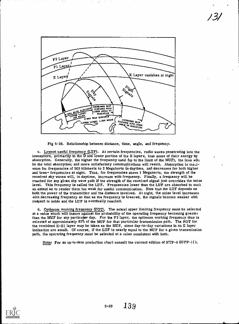
.-.
/3/
F2 Layer/
Fl La er // // /
E Layer1/ E Layer vanishes at night
INC UUU D slur
sil)
OISTANCI NITNLOIN
RADIATIONIS
A.NNI DRIPOISTANCI
(LORIS LATR) 1000 NIL'
Fig 5-20. Relationship between distance, time, angle, and frequency.
c. Lowest useful frequency (LUF). At certain frequencies, radio waves penetrating into theionosphere, primarily in the D and lower portion of the E layers, lose some of their energy byabsorption. Generally, the higher the frequeney used (up to the limit of the MUF), the less wilibe the total absorption; and more satisfactory communications will result. Absorption is ma;,i-mum for frequencies of 500 kilohertz to 2 Megahertz in daytime, and decreases for both higherand lowe.. frequencies at night. Thus, for frequencies above 1 Megahertz, the strength of thereceived sky waves will, in daytime, increase with frequency. Finally, a frequency will bereached for any given sky wave path U the strength of the received signal just overrides the noiselevel. This frequency is called the LUF. Frequencies lower than the LUF are absorbed to suchan extent as to render them too weak for useful communication. Note that the LUF depends onboth the power of the transmitter and the distance involved. At night, the noise level increaseswith decreasing frequency so that as the frequency is lowered, the signals become weaker withrespect to noise and the LUF is eventually reached.
d. 0 Umum wo_p uenc (F01). The actual upper limiting frequency must be selectedat a value which will insure against the probability of the operating frequency becoming greaterthan the MUF for any particular day. For the F2 layer, the optimum working frequency thus isselected at approximately 85% of the MUF for that particular transmission path. The FOT forthe combined E-El layer may be taken as the MUF, since day-to-day variations in an E layerionization are small. Of course, if the LUF is nearly equal to the MUF for a given transmissionpath, the operating frequency must be selected at a value consistent with both.
Note: For an uptodate prediction chart consult the current edition of NTP-6 SUPP-1( ).-
5-20 139
a .....1111111.111111111