document title for the traffic flow management
TRANSCRIPT

k
Final, Release 5, Revision 1
Contract Number: DTFAWA-04-C-00045
CDRL: E05
March 1, 2011
Prepared for:
U.S. Federal Aviation Administration
Prepared by:
CSC North American Public Sector – Civil Group
15245 Shady Grove Road Rockville, MD 20850
Document Title for the Traffic Flow Management-Modernization (TFM-M) Program
Traffic Flow Management System-to-Flight Schedule Monitor (TFMS-to-FSM) Interface Control Document (ICD) for the Traffic Flow Management-Modernization (TFM-M) Program

TFMS-to-FSM Interface Control Document CSC/TFMM-10/1077 March 2011 Release 5 FINAL, Revision 1
ii
Traffic Flow Management System-to-Flight Schedule Monitor (TFMS-to-FSM) Interface Control Document
(ICD) for the Traffic Flow Management-Modernization (TFM-M) Program
Final, Release 5, Revision 1
Contract Number: DTFAWA-04-C-00045
CDRL: E05
March 1, 2011
Prepared for:
U.S. Federal Aviation Administration
Prepared by:
CSC
North American Public Sector – Civil Group 15245 Shady Grove Road
Rockville, MD 20850

TFMS-to-FSM Interface Control Document CSC/TFMM-10/1077 March 2011 Release 5 FINAL, Revision 1
iii
CSC/TFMM-10/1077
Release 5, Final, Revision 1
March 1, 2011
INTERFACE CONTROL DOCUMENT
APPROVAL SIGNATURE PAGE
TFMS/FSM
APPROVAL SIGNATURES
PARTICIPANT NAME DATE

TFMS-to-FSM Interface Control Document CSC/TFMM-10/1077 March 2011 Release 5 FINAL, Revision 1
iv
Document History Record
Release Date Comment
Initial Draft June 2007 Draft delivery
Draft, Release 3 October 2, 2008 Contractual delivery. Addresses the following
Change Requests (CRs):
TFMMP00002069
TFMMP00003196
TFMMP00003802
TFMMP00003910
TFMMP00006550
TFMMP00007153
TFMMP00007184
TFMMP00007441
Revised Draft, Release 3 January 8, 2009 Delivery to address FAA comments and the
following CRs:
TFMMP00008703
TFMMP00009122
Final, Release 3 August 24, 2009 Contractual delivery. Addresses the following
CRs:
TFMMP00009053
TFMMP00009196
TFMMP00009555
TFMMP00026435
Final, Release 3, Revision 1 March 15, 2010 Contractual delivery. Addresses the following
CR:
TFMMP00027798

TFMS-to-FSM Interface Control Document CSC/TFMM-10/1077 March 2011 Release 5 FINAL, Revision 1
v
Release Date Comment
Draft, Release 5 May 24, 2010 Contractual delivery. Addresses Release 5
Interface Design.
This version reflects significant restructuring of
the Release 3 Final Revision to improve the
flow of information and also to enhance easy
maintenance.
Added Appendix B in which ADL File
Specification file is embedded as a document
link.
Added Appendix C in which FSM ADL
Parameter Specification file is embedded as a
document link.
Added Appendix D in which the CDM
Message Protocol file is embedded as a
document link.
Added Delay Program Rate and Delay
Program Parameters Messages.
Added UBRG to the list of values for the
TYPE field of a Substitution Good Response
Message
Final, Release 5 August, 5, 2010 Delivery to address FAA comments
Table 3-III: Clarified the definitions for the
following Control Types: ABRG, ADPT, DAS,
GAAP and RCTL
Revised ADL File Specification V 12.3
posted in Appendix B
Revised FSM ADL Parameters Specification
V 5.4 posted in Appendix C
Revised CDM Messages Protocol V 1.0
posted in Appendix D
Final, Release 5, Revision 1 March 1, 2011 Addresses the following CRs:
TFMMP00032363
TFMMP00032463

TFMS-to-FSM Interface Control Document CSC/TFMM-10/1077 March 2011 Release 5 FINAL, Revision 1
iii
Table of Contents 1 Scope...................................................................................................... 1-1 1.1 Scope and Purpose ................................................................................ 1-1 1.2 Subsystem Responsibility List ................................................................ 1-1 1.3 Document Organization .......................................................................... 1-1 2 Applicable Documents ............................................................................ 2-1
2.1 Government Documents ......................................................................... 2-1 2.2 Non-Government Documents ................................................................. 2-2 2.3 Document Sources ................................................................................. 2-3 2.3.1 Source of FAA Documents ..................................................................... 2-3 2.3.2 Request for Comment (RFC) Documents ............................................... 2-3
2.3.3 ISO, IEEE, and ANSI Documents ........................................................... 2-3 3 Interface Characteristics ......................................................................... 3-1
3.1 General Characteristics .......................................................................... 3-1
3.2 Functional Design Characteristics .......................................................... 3-3 3.2.1 Application Processes (APs) ................................................................... 3-3 3.2.1.1 Identification of Application Processes ................................................... 3-3
3.2.1.2 Category of Services Required by the AP ............................................... 3-4 3.2.1.2.1 Application Services Identification .......................................................... 3-4
3.2.1.3 Information Units ..................................................................................... 3-4 3.2.1.3.1 Information Code .................................................................................... 3-4 3.2.1.3.2 Information Structure .............................................................................. 3-4
3.2.1.3.2.1 Aggregate Demand List .......................................................................... 3-7
3.2.1.3.2.2 FSM Broadcast Request ......................................................................... 3-7
3.2.1.3.2.3 FSM Broadcast Reply ............................................................................. 3-7 3.2.1.3.2.4 FSM Broadcast Message ........................................................................ 3-7
3.2.1.3.2.5 Slot Credit Substitution Message (SCS) ................................................. 3-8 3.2.1.3.2.6 Substitution Good Responses .............................................................. 3-10 3.2.1.3.2.7 Substitution Error Responses ............................................................... 3-17
3.2.1.3.2.8 EDCT and Other Commands ................................................................ 3-21 3.2.1.3.2.9 EDCT LIST ........................................................................................... 3-24
3.2.1.3.2.10 EDCT SUB SHOW ............................................................................... 3-28 3.2.1.3.2.11 EDCT SLIST ......................................................................................... 3-33 3.2.1.3.2.12 EDCT UNASSIGNED SLOTS ............................................................... 3-35
3.2.1.3.2.13 Delay Program Rate Messages ............................................................ 3-36
3.2.1.3.2.14 Delay Program Parameters Messages ................................................. 3-37 3.2.1.3.2.15 Heartbeat Message .............................................................................. 3-38 3.2.1.3.3 Information Unit Segmentation ............................................................. 3-38
3.2.1.3.4 Direction of Information Flow ................................................................ 3-38 3.2.1.3.5 Frequency of Transmission ................................................................... 3-38 3.2.1.3.6 Responses ............................................................................................ 3-38 3.2.1.4 Quality of Service .................................................................................. 3-38 3.2.1.5 AP Error Handling ................................................................................. 3-39 3.2.1.6 Summary Table .................................................................................... 3-39 3.2.2 Protocol Implementation ....................................................................... 3-40

TFMS-to-FSM Interface Control Document CSC/TFMM-10/1077 March 2011 Release 5 FINAL, Revision 1
vii
3.2.2.1 Application Services ............................................................................. 3-41 3.2.2.2 Network Services .................................................................................. 3-41 3.2.2.3 Naming and Addressing........................................................................ 3-42
3.2.3 Security ................................................................................................. 3-42 3.2.4 Interface Design Characteristics Table ................................................. 3-42 3.3 Physical Design Characteristics ............................................................ 3-43 3.3.1 Electrical Power and Electronic Characteristics .................................... 3-45 3.3.1.1 Connectors ........................................................................................... 3-45
3.3.1.2 Wire/Cable ............................................................................................ 3-45 3.3.1.3 Electrical Power/Grounding .................................................................. 3-45 3.3.1.4 Fasteners .............................................................................................. 3-45 3.3.1.5 Electromagnetic Compatibility ............................................................... 3-45
4 Verification Provisions............................................................................. 4-1 4.1 Responsibility for Verification .................................................................. 4-1 4.1.1 Pre-OT&E ............................................................................................... 4-1
4.1.2 OT&E ...................................................................................................... 4-1
4.1.3 KSAT ...................................................................................................... 4-1 4.2 Test Environments .................................................................................. 4-1 4.3 Special Verification Requirements .......................................................... 4-2
4.4 Verification Requirements Traceability Matrix (VRTM) ........................... 4-2 5 Preparation for Delivery .......................................................................... 5-1
6 Notes ...................................................................................................... 6-1 6.1 Definitions ............................................................................................... 6-1 6.2 Abbreviations and Acronyms .................................................................. 6-1
Appendix A FSM – TFMS Tools ...................................................................................A-1 Appendix B ADL & FSM Broadcast File Format Specifications ....................................B-1
Appendix C FSM ADL Parameters Specification ........................................................ C-1 Appendix D CDM Message Protocol ........................................................................... D-1
List of Tables Table 3-I. TFMS-to-FSM Interface Messages .............................................................. 3-5 Table 3-II. Slot Credit Substitution (SCS) Message ..................................................... 3-8 Table 3-III. Substitution Good Response Message .................................................... 3-10 Table 3-IV. Error Code Messages .............................................................................. 3-18
Table 3-V. Report Request ......................................................................................... 3-23
Table 3-VI. EDCT List ................................................................................................ 3-25
Table 3-VII. EDCT Sub Show ..................................................................................... 3-29 Table 3-VIII. EDCT SLIST .......................................................................................... 3-34 Table 3-IX. EDCT UNASSIGNED SLOTS .................................................................. 3-35 Table 3-X. Delay Program Rate Message .................................................................. 3-36 Table 3-XI. TFMS-to-FSM Interface Summary ........................................................... 3-39
Table 3-XII. Interface Design Characteristics of the TFMS to FSM Interface ............. 3-42

TFMS-to-FSM Interface Control Document CSC/TFMM-10/1077 March 2011 Release 5 FINAL, Revision 1
viii
List of Figures Figure 3-1. TFMS-to-FSM Interface Block Diagram ..................................................... 3-2 Figure 3-2. OSI Layer Functional Interface Connectivity Diagram for TFMS-to-FSM . 3-41 Figure 3-3. TFMS-to-FSM Physical Diagrams ............................................................ 3-44
Figure A-1. Reset AAR Window ................................................................................... A-3 Figure A-2. Modify AAR Window .................................................................................. A-5 Figure A-3. Delete Program Parameters Window ........................................................ A-6

TFMS-to-FSM Interface Control Document CSC/TFMM-10/1077 March 2011 Release 5 FINAL, Revision 1 Scope
1-1
1 Scope
This section identifies the scope, purpose, and organization of this Interface Control
Document (ICD) and identifies the subsystem responsibility list.
1.1 Scope and Purpose
This ICD provides the design characteristics of the interface between the Traffic
Flow Management System (TFMS) and the Flight Schedule Monitor (FSM) as it is
implemented for TFMS Build 3. This ICD satisfies the interface design requirements
contained in the Traffic Flow Management System Interface Requirements
Specification (IRS) for Traffic Flow Management Modernization (TFM-M), Release
5 Revision 4.1, dated September 14, 2010. The IRS is a companion document to the
System/Subsystem Specification (SSS) for the Traffic Flow Management–
Modernization (TFM-M), Release 5 Revision 7.1 dated September 14, 2010. This
ICD was prepared under guidance from FAA-STD-025e, dated August 9, 2002 and
the TFMM-ENGR-05(E05), Traffic Flow Management Modernization (TFM-M),
Data Item Description (DID) for ICDs.
The purpose of this ICD is to specify:
Interface connectivity between TFMS and FSM
Format of data transmitted between FSM and TFMS
1.2 Subsystem Responsibility List
The following list provides the TFMS external system interface and identifies the
responsible Federal Aviation Administration (FAA) organizations:
TFMS - FAA-ATO-R
FSM - FAA-ATO-R
1.3 Document Organization
This ICD is organized in six sections and one appendix:
Section 1, Scope, describes the purpose and scope of this ICD.
Section 2, Applicable Documents, provides a listing of referenced government and
non-government documents, and document sources researched and used by this ICD.
Section 3, Interface Characteristics, identifies and describes the general
characteristics, functional design, and physical design characteristics for this ICD.
Section 4, Verification Provisions, contains verification provisions for this ICD.
Section 5, Preparation for Delivery, contains any specific preparations required by
this ICD.

TFMS-to-FSM Interface Control Document CSC/TFMM-10/1077 March 2011 Release 5 FINAL, Revision 1 Scope
1-2
Section 6, Notes, provides a list of definitions, abbreviations, and acronyms used in
this ICD.
Appendix A, FSM – TFMS Tools, provides a description of each of the FSM
commands that result in FSM – TFMS data exchange.
Appendix B, ADL & FSM Broadcast File Format Specifications, provides a
detailed description of the ADL and FSM Broadcast file formats and naming
conventions.
Appendix C, FSM ADL Parameters Specification, provides a detailed description
of the FSM delay program parameters associated with proposed and actual delay
programs. FSM provides these parameters to TFMS and TFMS includes these
parameters, as received, in subsequent ADL file distribution.
Appendix D, CDM Message Protocol, details the application, connectivity and the
protocols used by TFMS to exchange messages via the CDM participant (AOCNet,
FSM, and ARINC) client interface.
TFMS-to-FSM Interface Control Document CSC/TFMM-10/1077 March 2011 Release 5 FINAL, Revision 1 Applicable Documents
2-1
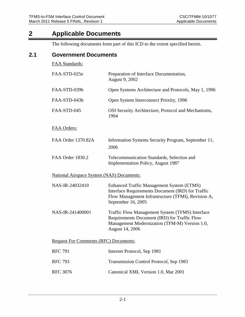
2 Applicable Documents
The following documents form part of this ICD to the extent specified herein.
2.1 Government Documents
FAA Standards:
FAA-STD-025e Preparation of Interface Documentation,
August 9, 2002
FAA-STD-039b Open Systems Architecture and Protocols, May 1, 1996
FAA-STD-043b Open System Interconnect Priority, 1996
FAA-STD-045 OSI Security Architecture, Protocol and Mechanisms,
1994
FAA Orders:
FAA Order 1370.82A Information Systems Security Program, September 11,
2006
FAA Order 1830.2 Telecommunication Standards, Selection and
Implementation Policy, August 1987
National Airspace System (NAS) Documents:
NAS-IR-24032410 Enhanced Traffic Management System (ETMS)
Interface Requirements Document (IRD) for Traffic
Flow Management Infrastructure (TFMI), Revision A,
September 16, 2005
NAS-IR-241400001 Traffic Flow Management System (TFMS) Interface
Requirements Document (IRD) for Traffic Flow
Management Modernization (TFM-M) Version 1.0,
August 14, 2006
Request For Comments (RFC) Documents:
RFC 791 Internet Protocol, Sep 1981
RFC 793 Transmission Control Protocol, Sep 1983
RFC 3076 Canonical XML Version 1.0, Mar 2001

TFMS-to-FSM Interface Control Document CSC/TFMM-10/1077 March 2011 Release 5 FINAL, Revision 1 Applicable Documents
2-2
Other Government Documents:
CSC/TFMM-04/0025 System/Subsystem Specification (SSS) for the Traffic
Flow Management–Modernization (TFM-M) Program,
Release 5, Revision 7.1, September 14, 2010
CSC/TFMM-11/1247 Final Information Systems Security Plan (ISSP) - Fiscal
Year (FY) 2011 for Traffic Flow Management–
Modernization (TFM-M), February 28, 2011
CSC/TFMM-05/0121 Interface Requirements Specification (IRS) for the
Traffic Flow Management – Modernization (TFM-M)
Program, Release 5, Revision 4.1, September 14, 2010
CSC/TFMM-10/1077 Traffic Flow Management System-to-Airline
Operations Center Network (TFMS-to-AOCNet)
Interface Control Document (ICD), Release 5, Final,
Revision 1, March 1, 2011
FCM-H1-2005 Federal Meteorological Handbook No 1: Surface
Weather Observations and Reports, September 1, 2005
ND319705 Weather Service Operations Manual (WSOM),
Chapter D-31, Aviation Terminal Forecasts, June 6,
1997
TFMM-ENGR-05(E05) Traffic Flow Management Modernization (TFM-M),
Data Item Description (DID), undated
VNTSC-TFM-RM-007 ETMS Reference Manual Volume I, Version 8.5,
November 2007
DCN 31F08007-015-R0 ETMS Reference Manual Volume II: FSM User’s
Guide, Version 8.5 Client
Metron Aviation ICD FSM/Autosend Server Communications Interface,
Version 1.2, June 28, 2005
CSC Memorandum Web Coversheet Dictionary FSM 9.0v6,
November 11, 2010
2.2 Non-Government Documents
International Organization for Standardization (ISO):
ISO/IEC 7498-1 Information Processing Systems – Open Systems

TFMS-to-FSM Interface Control Document CSC/TFMM-10/1077 March 2011 Release 5 FINAL, Revision 1 Applicable Documents
2-3
Interconnect – Basic Reference Model, 1993
Institute of Electrical and Electronics Engineers (IEEE):
IEEE 802.3 IEEE Standard for Information Technology —
Telecommunications and Information Exchange
Between Systems, 2000
American National Standards Institute (ANSI):
ANSI X3.4 American National Standard Code for Information
Interchange (ASCII), Rev. 1992
2.3 Document Sources
This subsection provides sources for FAA and International Organization for
Standardization (ISO) documents.
2.3.1 Source of FAA Documents
Copies of FAA specifications, standards, and publications may be obtained from the
Contracting Officer, Federal Aviation Administration, 800 Independence Avenue
S.W., Washington, DC, 20591. Requests should clearly identify the desired material
by number and date and state the intended use of the material.
2.3.2 Request for Comment (RFC) Documents
RFC documents are available from the reference area electronically at the following
Web address:
http://www.faqs.org/rfcs/
2.3.3 ISO, IEEE, and ANSI Documents
Copies of ISO, IEEE, and ANSI standards may be obtained from the American
National Standards Institute, 11 West 42nd Street, New York, NY, 10036.

TFMS-to-FSM Interface Control Document CSC/TFMM-10/1077 March 2011 Release 5 FINAL, Revision 1 Interface Characteristics
3-1
3 Interface Characteristics
This section provides the general, functional, and physical interface characteristics
for the TFMS interface with FSM.
3.1 General Characteristics
The Flight Schedule Monitor (FSM) was developed for the FAA by Metron
Aviation, providing the FAA, NavCanada, and Collaborative Decision Making
(CDM) participating users with the capability to monitor airport capacity/demand
balance, model traffic flow management initiatives, and evaluate alternative
approaches. FSM provides common situational awareness to FSM users by
presenting airport demand and capacity information with both graphics and text.
FSM contains several rationing schemes that seek to maintain an efficient and
equitable balance between capacity and demand. FSM is also used by the Air Traffic
Control System Command Center (ATCSCC) to implement Ground Stop (GS) and
Ground Delay Program (GDP) strategies. Airline Operations Centers use FSM to
assess the proposed GS/GDP, develop strategies to cope with the restrictions, and
monitor GS/GDP initiatives that are in effect. FSM is used by more than 30 FAA
facilities, 40 airlines, and an increasing General Aviation community in the United
States and Canada.
The TFMS-to-FSM interface described in this ICD is from the FSM Server to the
TFMS TPC.
Figure 3-1, TFMS-to-FSM Interface Block Diagram, illustrates the TFMS-to-FSM
interface and the demarcation point for the FSM to TPC. The demarcation point is
illustrated as a black dot.

TFMS-to-FSM Interface Control Document CSC/TFMM-10/1077 March 2011 Release 5 FINAL, Revision 1 Interface Characteristics
3-2
Figure 3-1. TFMS-to-FSM Interface Block Diagram
The TFMS-to-FSM interface transfers data via three communications paths
(depending on the FSM Server entity interfacing), as detailed below:
Via the FAA FTI Ops-IP Gateway – This pathway enables data transfers via a
closed “trusted’ high speed connection system (primarily at the ATCSCC). This
FSM at the Internal TRSs
FAA
Portal
Subsystem
FSM
Server
TFMS TPC
TFMS-to-FSM Interface Block Diagram
Router
FSM Using FTI Ops-IP WAN
Firewall Router
FAA Ops-IP
WAN
FSM at External TRSs &
Canadian Command Center
External
Portal
Subsystem
FSM
Server
TFMS TPC
RouterRouter SwitchVPN /
Internet
FSM Using AOCNET/CDM WAN via NESG
FSM at CDM Participant Sites
AOCNET /
CDM WAN
FSM
ServerRouter
F T
I - N E
S G
Firewall
Canadian Traffic
FSM Using VPN/Internet or Leased Circuit via NESG

TFMS-to-FSM Interface Control Document CSC/TFMM-10/1077 March 2011 Release 5 FINAL, Revision 1 Interface Characteristics
3-3
allows communications to and from FSM Servers, through the Ops-IP Gateway
into a designated TFMS router and then through the FAA Portal Subsystem for
further processing. The interface uses the standard TCP/IP protocols for
communications. The demarcation point is at the TFMS router.
Via the National Airspace System (NAS) Security Gateway (NESG) – This
pathway enables data transfers via the NESG communication system. NESG is a
closed “untrusted’ high speed connection system, allowing a communications link
to specified an External TRS (ETRS) and other designated systems. The External
TRSs connect to the NESG via the VPN/Internet. The Canadian traffic flows into
the NESG via a dedicated circuit. This allows communications to and from FSM
Servers, through the NESG Gateway, into a designated TFMS router and switch,
and then into the External Portal Subsystem for further processing. The interface
uses the standard TCP/IP protocols for communications. The demarcation point is
at the TFMS switch.
Via the AOCNET/CDM Wide Area Network – This pathway enables data
transfers to the FSM Servers via the AOCNET/CDM WAN. The AOCNet/CDM
WAN is an open ‘untrusted’ system used by airlines and other entities for FSM
communications. This allows communications from the FSM Servers to
communicate through the AOCNET/CDM WAN (maintained by Aeronautical
Radio INC) into the NESG over to the designated TFMS router and switch, and
then to the External Portal Subsystem for further processing. The interface uses
the standard TCP/IP protocols for communications. The demarcation point is at
the TFMS switch.
Refer to Section 3.3 for a detailed physical detailing of the TFMS-to-FSM Interface.
3.2 Functional Design Characteristics
This subsection describes the functional design characteristics of the TFMS and
FSM.
3.2.1 Application Processes (APs)
This subsection identifies each application process and the applicable services,
including performance characteristics (information units, quality of service, error
handling, and responses).
3.2.1.1 Identification of Application Processes
The TFMS uses the following APs to send and receive data from FSM:
FTI Ops-IP WAN – This interface AP is the FAA Portal Message Interface
Server located in the FAA Portal Subsystem
VPN/Internet via NESG – This interface AP is the External Portal Message
Interface Server located in the External Portal Subsystem
AOCNET/CDM WAN – This interface AP is also the External Portal Message
Interface Server located in the External Portal Subsystem

TFMS-to-FSM Interface Control Document CSC/TFMM-10/1077 March 2011 Release 5 FINAL, Revision 1 Interface Characteristics
3-4
The corresponding FSM AP is the FSM Server AP.
3.2.1.2 Category of Services Required by the AP
Loss of the TFMS-to-FSM interface will impair full system operation, but will not
degrade TFMS operations to the point of inoperability. This interface is designated
“essential” IAW NAS-SR-1000.
3.2.1.2.1 Application Services Identification
The TFMS-to-FSM interface is used to transfer the following data from FSM:
Aggregate Demand List Requests
FSM Broadcast Request
Substitution Messages
EDCT Control Commands and Report Requests
Delay Program Rates
Delay Program Parameters
Heartbeat Message
The TFMS-to-FSM interface is used to transfer the following data to FSM:
Aggregate Demand List
FSM Broadcast Response
FSM Broadcast Message
Substitution Message Responses
EDCT Control Command Responses and Reports
Heartbeat Acknowledgements
3.2.1.3 Information Units
This subsection describes the formats of the data transferred between FSM and
TFMS.
3.2.1.3.1 Information Code
All TFMS-to-FSM interface messages are encoded in American Standard Code for
Information Interchange (ASCII) alphanumeric data format in accordance with ANSI
X3.4, American National Standard Code for Information Interchange (ASCII), Rev.
1992., as described in Section 3.2.1.3.2, and the appropriate subsections.
In addition, the FSM Broadcast Message and one element of the Aggregate Demand
List (ADL) are encoded in XML, an ASCII-based encoding format (conforming to
the documentation in the previous paragraph), in accordance with RFC 3076,
Canonical XML Version 1.0, Mar 2001.
3.2.1.3.2 Information Structure
The following subsections provide the detailed record layout of the products sent by
the FSM. Table 3-I, TFMS-to-FSM Interface Messages Table, presents the TFMS-

TFMS-to-FSM Interface Control Document CSC/TFMM-10/1077 March 2011 Release 5 FINAL, Revision 1 Interface Characteristics
3-5
to-FSM Interface Messages, including the subsection reference and mnemonic.
Table 3-I. TFMS-to-FSM Interface Messages
Product Name Product
Mnemonic ICD Subsection
Aggregate Demand List ADL 3.2.1.3.2.1
FSM Broadcast Request --- 3.2.1.3.2.2
FSM Broadcast Reply --- 3.2.1.3.2.3
FSM Broadcast Message FBCM 3.2.1.3.2.4
Slot Credit Substitution Message SCS 3.2.1.3.2.5
Substitution Good Responses N/A 3.2.1.3.2.6
Substitution Error Responses N/A 3.2.1.3.2.7
EDCT and Other Commands N/A 3.2.1.3.2.8
EDCT List EDCT List 3.2.1.3.2.9
EDCT Sub Show EDCT Sub Show 3.2.1.3.2.10
EDCT SList EDCT SList 3.2.1.3.2.11
EDCT Unassigned Slots EDCT Unassigned
Slots
3.2.1.3.2.12
Delay Program Rate Messages AAR or ADR 3.2.1.3.2.13
Delay Program Parameters Messages GDP (or GS or AFP)
PARAM, COMP
PARAM, or BLANK
PARAM
3.2.1.3.2.14
Heartbeat Message HB 3.2.1.3.2.15
The following syntax rules are used for field specifiers in the ASCII Tables
following the following subsections. Below these rules are the conventions for XML
entries.
L – represents one upper-case letter in ASCII
d – represents one numeric digits in ASCII
n – represents one integer in ASCII
a – represents one alphanumeric (either number or upper-case letter) in ASCII
[] – means the characters enclosed are optional. Any characters not within
brackets are required. For example, Ldd [aa] would indicate an upper-case letter,
followed by two digits, and then zero, one, or two optional alphanumeric
characters.
BOLD indicates a static entry.
ITALIC entries are optional to the message

TFMS-to-FSM Interface Control Document CSC/TFMM-10/1077 March 2011 Release 5 FINAL, Revision 1 Interface Characteristics
3-6
All times, unless specified will be in DayDayhourhourminuteminute (DDhhmm)
format
The following rules apply to the XML schema:
The files contain only printable ASCII characters.
The file format follows standard XML structural conventions.
In XML terminology, the files are guaranteed to be:
o Valid – The XML file content matches the proper schema and
documentation.
o "Well-Formed." - This means that every opening tag (i.e. - <TAG>) has a
corresponding closing tag (i.e. - </TAG>), opening and closing tag pairs
are correctly matched and nested, and consistent capitalization is used.
Note - The first line of every file is the standard "<?XML ...>" entry,
identifying the XML version number. This is the only tag which has no
corresponding close tag.
o Simple - Only a simple subset of XML is used. All data is between
matching start and end tags:
<TAG>data</TAG>
The files do not contain data in any other XML form. For example,
composite tags (e.g., <TAG=“data”/>) and attributes are never used. Note
- New-line characters between matching start and end tags are part of the
element's data.
o Structured – The XML file consists of data element (or simply an
element), consisting of a pair of matching start and end tags, together with
the data between them. Elements can contain other elements, and are
referred to as a container. The container element is considered to be the
‘parent’ to the elements contained within. Elements contained within the
‘parent’ container are considered ‘child’ elements. Example:
<CTR_ROUTE>
<CTR_SEG>...</CTR_SEG>
</CTR_ROUTE>
Only a simple subset of XML is used. All data is between matching start
and end tags: <TAG>data</TAG>
Characters that are not between matching start and end tags are ignored.
They are and may be used occasionally for comments or enhancements of
clarity. Example:
<TAG1>
<TAG2>This is data </TAG2>
This is a comment.
<TAG2>This is data</TAG2>
</TAG1>

TFMS-to-FSM Interface Control Document CSC/TFMM-10/1077 March 2011 Release 5 FINAL, Revision 1 Interface Characteristics
3-7
Data elements can be in any order within their container element's tag pair
(if element is a child of a parent element) or within the file (if an element
not acting as a container).
3.2.1.3.2.1 Aggregate Demand List
The ADL is the primary product that drives FSM and is used by many AOCNET
Participants. It is an ASCII file consisting of two distinct parts, the header and the
data update sections. It is comprised of data extracted from the TFMS databases,
which are maintained with a combination of:
Official Airline Guide (OAG) data
Airline-provided flight data messages (FC, FX, FM, EI, and OOOI data)
NAS messages generated from the ATC system (FZ, DZ, RZ, AZ, AF, UZ, and
TZ data messages)
Issued ground delays (EDCTs – CTs for individual delays, FA for blanket
delays)
GDP-specific data entered by traffic management specialists using AOCNET.
Refer to Appendix B ADL & FSM Broadcast File Format Specifications for a
detailed description of the ADL file format.
3.2.1.3.2.2 FSM Broadcast Request
A client application, (in this case, FSM) requests that an FSM Broadcast message be
sent from the TFMS. The format of the request is completely contained within a
CDM Protocol message and no explicit application message is sent by the client.
Refer to the M_AUTO_MONITOR_REQ protocol message (located in Appendix D)
for details.
3.2.1.3.2.3 FSM Broadcast Reply
The FSM Broadcast Reply Message is sent by the TFMS as a reply to a FSM
Broadcast Request Message from a client application (typically FSM). The format
of the message is identical to the format of the FSM Broadcast Message. Refer to
the M_AUTO_MONITOR_REPLY protocol message (located in Appendix D) and
Section 3.2.1.3.2.4 (FSM Broadcast Message) for details.
3.2.1.3.2.4 FSM Broadcast Message
TFMS sends an FSM Broadcast Message (separate from ADLs) to notify
applications, primarily FSM, of two sets of dynamic data:
The current traffic management initiatives that are proposed, in place, or have
been purged on this day,
The current FEAs and FCAs that are available for monitoring with FSM.
Refer to Appendix B, ADL & FSM Broadcast File Format Specifications, for a
detailed description of the FSM Broadcast Message format.

TFMS-to-FSM Interface Control Document CSC/TFMM-10/1077 March 2011 Release 5 FINAL, Revision 1 Interface Characteristics
3-8
3.2.1.3.2.5 Slot Credit Substitution Message (SCS)
A slot credit substitution request can be submitted to TFMS using the SCS message.
The format of the SCS message differs from the other CDM messages in that the
format is completely fixed. Special fields are used in the SCS that cannot be
modified by the CDM Flight Modify (FM) message (see TFMS-to-AOCnet Interface
Control Document). This was done because the additional fields in an SCS message
are not flight attributes that are stored by TFMS. Rather, they are temporary values
used only in the processing of the request.
An SCS message uses the fields specified in Table 3-II, in the indicated order.
Table 3-II. Slot Credit Substitution (SCS) Message
Field Designation Unit/Format Description Bytes
Field 01 Message type SCS Static Entry - SCS 3
Field 02
Flight Identification La[a][a][a][a]
[a]
Flight call sign (Flight ID) as it
appears in the OAG and/or
subsequently will be filed on the
NAS flight plan. Only the
aircraft identification portion of
the NAS syntax is accepted (i.e.,
the computer IDs are not used
here). Flight IDs must match the
NAS flight plan exactly. IDs
consisting of a 3-letter code and
a flight number should use
leading zeros on the flight
number only if they will be filed
that way on the flight plan.
2-7
Field 26 Departure Airport
(NAS Departure
Point)
aaa[a] ICAO identifier for the airport
of origin for this flight leg.
TFMS also accepts published
FAA 3-letter designator for
CONUS airports.
3 - 4
Field 27 Arrival Airport aaa[a] ICAO identifier for the
destination airport for this flight
leg. TFMS also accepts
published FAA three-letter
designator for CONUS airports.
Called Destination in NAS.
Example - JFK, KJFK, 32G
3 - 4
Field A1 UTC Departure
Date/Time
dddddddd Date/time on which the flight
leg was originally scheduled to
depart the gate. Format is
MMDDhhmm, and must be 8
digits, zero padded.
This field is used as part of the
unique identification of a flight
8

TFMS-to-FSM Interface Control Document CSC/TFMM-10/1077 March 2011 Release 5 FINAL, Revision 1 Interface Characteristics
3-9
Field Designation Unit/Format Description Bytes
leg.
Example - 06261225
No tag Yielded Slot Laadddddda
Or
FCAaaadddddd
a
Slot designator. The format is a
concatenation of:
Airport name: 3 or 4
characters or FCA name :
FCA followed by up to 3
characters
Slot date and time: Format is
DDhhmm, and must be
6digits, zero padded.
1-letter suffix: The suffix
letter is used to ensure that
slot name is unique
10-14
No tag Earliest Acceptable
Time
dddddd Earliest acceptable time the
aircraft will take. Format is
DDhhmm, and must be 6 digits,
zero padded.
6
No tag Latest Acceptable
Time
dddddd Latest acceptable time the
aircraft will take. Format is
DDhhmm, and must be 6 digits,
zero padded.
6
Sample Slot Credit Substitution (SCS) Message for a GDP
SCS UNA1277 DFW SFO 03241701 SFO.242040A 242050 242120
Sample Slot Credit Substitution (SCS) Message for an AFP
SCS UNA1277 DFW SFO 03241701 FCAA02.242040A 242050 242120
The fields contained in the above examples have the following meaning:
SCS – This is an SCS request message type. (Required)
UNA1277 – The ID of the flight to be subbed into the new slot. (Required)
DFW – The origin of the flight. (Required)
SFO – The destination of the flight. (Required)
03241701 – The original departure date/time for the flight. (Required)
SFO.242040A – The yielded slot. (Required)
242050 – The earliest acceptable time for the new slot. (Required)
242120 – The latest acceptable time for the new slot. (Required)
TFMS-to-FSM Interface Control Document CSC/TFMM-10/1077 March 2011 Release 5 FINAL, Revision 1 Interface Characteristics
3-10
In addition, there are other notes that provide guidance on ECR messages:
The SCS message is allowed only in an SS packet. The SS packet
M_SS_Data_Packet [112] is described in detail in Appendix D. The only
message FSM sends in an SS packet is the SCS message.
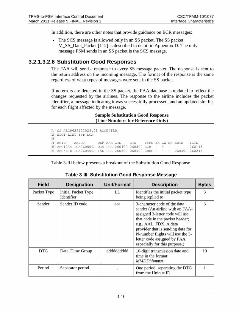
3.2.1.3.2.6 Substitution Good Responses
The FAA will send a response to every SS message packet. The response is sent to
the return address on the incoming message. The format of the response is the same
regardless of what types of messages were sent in the SS packet.
If no errors are detected in the SS packet, the FAA database is updated to reflect the
changes requested by the airlines. The response to the airline includes the packet
identifier, a message indicating it was successfully processed, and an updated slot list
for each flight affected by the message.
Sample Substitution Good Response
(Line Numbers for Reference Only) (1) SS ABC0625121029.01 ACCEPTED.
(2) SLOT LIST for LGA
(3)
(4) ACID ASLOT DEP ARR CTD CTA TYPE EX CX SH ERTA IGTD
(5) ABC1234 LGA260500A DCA LGA 260400 260500 ECR - Y - - 260145
(6) ABC5678 LGA260400A IAD LGA 260300 260400 SBRG - - - 260400 260245
Table 3-III below presents a breakout of the Substitution Good Response
Table 3-III. Substitution Good Response Message
Field Designation Unit/Format Description Bytes
Packet Type Initial Packet Type
Identifier
LL Identifies the initial packet type
being replied to
3
Sender Sender ID code aaa 3-character code of the data
sender (An airline with an FAA-
assigned 3-letter code will use
that code in the packet header;
e.g., AAL, FDX. A data
provider that is sending data for
N-number flights will use the 3-
letter code assigned by FAA
especially for this purpose.)
3
DTG Date /Time Group dddddddddd 10-digit transmission date and
time in the format:
MMDDhhmmss
10
Period Separator period . One period, separating the DTG
from the Unique ID.
1

TFMS-to-FSM Interface Control Document CSC/TFMM-10/1077 March 2011 Release 5 FINAL, Revision 1 Interface Characteristics
3-11
Field Designation Unit/Format Description Bytes
Unique Unique identifier dd 2 digits for uniqueness (in case
multiple messages are generated
in the same second)
2
Space Space [ ] One space separating the Unique
code from the Processed entry
1
Accepted Accepted ACCEPTED Shows the identifier of the
packet that is being replied to.
The word “ACCEPTED”
indicates that the processing of
the packet was successful.
8
Data ID Data Identifier ATCSCC
EDCT FLOW
CONTROL
DEPARTURE
TIME
Static Entry - ATCSCC EDCT
FLOW CONTROL
DEPARTURE TIME
39
Headers Slot List Data
Headers ACID
ASLOT
DEP ARR
CTD CTA
TYPE EX CX
SH EENTRY
(or) ERTA
IGTD
Header for the following data
fields:
ACID – Aircraft identifier
ASLOT – Arrival Slot
DEP – Departure Airport
ARR – Arrival Airport
CTD – Controlled Time of
Departure
CTA –Controlled Time of
Arrival
TYPE – Type of Entry
EX – Exempt Flag (Yes or
No)
CX – Control Flag (Yes or
No)
SH – Slot Hold flag (Yes or
No)
EENTRY – Earliest Entry
Time (for AFP)
or ERTA - Earliest Runway
Time of Arrival (for Airport
GDP)
IGTD - Initial Gate Time of
Departure
64

TFMS-to-FSM Interface Control Document CSC/TFMM-10/1077 March 2011 Release 5 FINAL, Revision 1 Interface Characteristics
3-12
Field Designation Unit/Format Description Bytes
SLOT LIST DATA FIELDS*
ACID Flight Identification Laa[a][a][a][a] Flight call sign as it appears in
the OAG and/or subsequently
will be filed on the NAS flight
plan. Padded with spaces to
equal 8 bytes.
8
ASLOT
Arrival Slot LLL[Laa].dddd
ddL
or
FCAaaa.ddddd
dL
The time slot reserved at the
airport or FCA for this flight to
arrive as follows:
Name – airport or FCA
name. An airport name can
be three or four characters
and can include letters and
numbers. An FCA name
must be the entry FCA
followed by three
alphanumeric characters.
The name is separated from
the Date/Time by a period
for readability
Date/Time – Slot date and
time. The format is
DDhhmm (padded as
necessary)
Suffix Letter - The suffix
letter is used to ensure that
slot name is unique.
Note - An FCA name must be
six characters starting with the
literal letters “FCA”. The
remaining characters can be
either digits, upper-case letters,
dash (“-“), or underscore (“_”).
An FCA name cannot end with
an underscore. Padded with
spaces to equal 15 bytes.
15
DEP Departure Airport LLL[L] Departure airport code in
standard 3 or 4 letter identifier,
padded with spaces to equal 5
bytes
5

TFMS-to-FSM Interface Control Document CSC/TFMM-10/1077 March 2011 Release 5 FINAL, Revision 1 Interface Characteristics
3-13
Field Designation Unit/Format Description Bytes
ARR Arrival Airport LLL[L]
Arrival airport code in standard
3 or 4 letter identifier, padded
with spaces to equal 5 bytes.
Note - For a GDP, the arrival
airport will be the same for
every flight; for an AFP, they
may differ. It is padded with
spaces to equal 5 bytes
5
CTD Controlled Time of
Departure
dddddd The time the flight should take
off In the format DDhhmm,
padded with spaces to equal 7
bytes
7
CTA Controlled Time of
Arrival
dddddd The time the flight should arrive
at the controlled airport or FCA
(e.g., 260400). In the format
DDhhmm, padded with spaces
to equal 7 bytes
7
TYPE
Control Type LLL[L] The source of the current control
times for this flight (e.g. GDP).
The control types that can
appear in a slot list are:
ABRG – Control times were
assigned when the flight was
utilized to create a bridge in
order to adaptive compress a
slot.
ADPT – Control time
assigned when the flight was
adaptively compressed by
the TFMS adaptive
compression process (AFP
and GDP)
AFP – Control times were
computed as part of an
initial AFP, a revision to an
AFP, or an extension to an
AFP.
BLKT – Control times were
computed by a blanket
program.
COMP – Control times were
computed by compression.
DAS – Control time which
resulted from the
assignment of the average
delay to a pop-up flight
5

TFMS-to-FSM Interface Control Document CSC/TFMM-10/1077 March 2011 Release 5 FINAL, Revision 1 Interface Characteristics
3-14
Field Designation Unit/Format Description Bytes
which did not receive an
unassigned slot in an AFP or
GDP. For DAS based
programs this is used for the
initial delay assignments to
all pop-up flights. For
GAAP and UDP based
program, this control type is
used only if no unassigned
slot is available for the pop-
up. This control type is not
used for re-controlled
flights. (AFP and GDP)
ECR – Control times were
assigned by an FAA ECR
request.
GAAP – Control times are
the result of a GAAP or
UDP based AFP or GDP if a
pop-up or a re-control flight
is allocated to an unassigned
slot. This occurs for all pop-
up flights in a GAAP or
UDP based program when
an unassigned slot is
available for the flight.
However, only some classes
of re-controlled flights in a
GAAP or UDP are assigned
to unassigned slots. (e.g.,
those that occur after
dropping out of an AFP).
(AFP and GDP)
GDP – Control times were
computed as part of an
initial GDP, a revision to a
GDP, or an extension to a
GDP.
GS – Control times were
computed by a ground stop.
RCTL – Control time which
resulted from the
assignment of the average
delay to a flight that was at
some point controlled by a
GDP or AFP, which was
then purged or the flight
dropped out and was re-
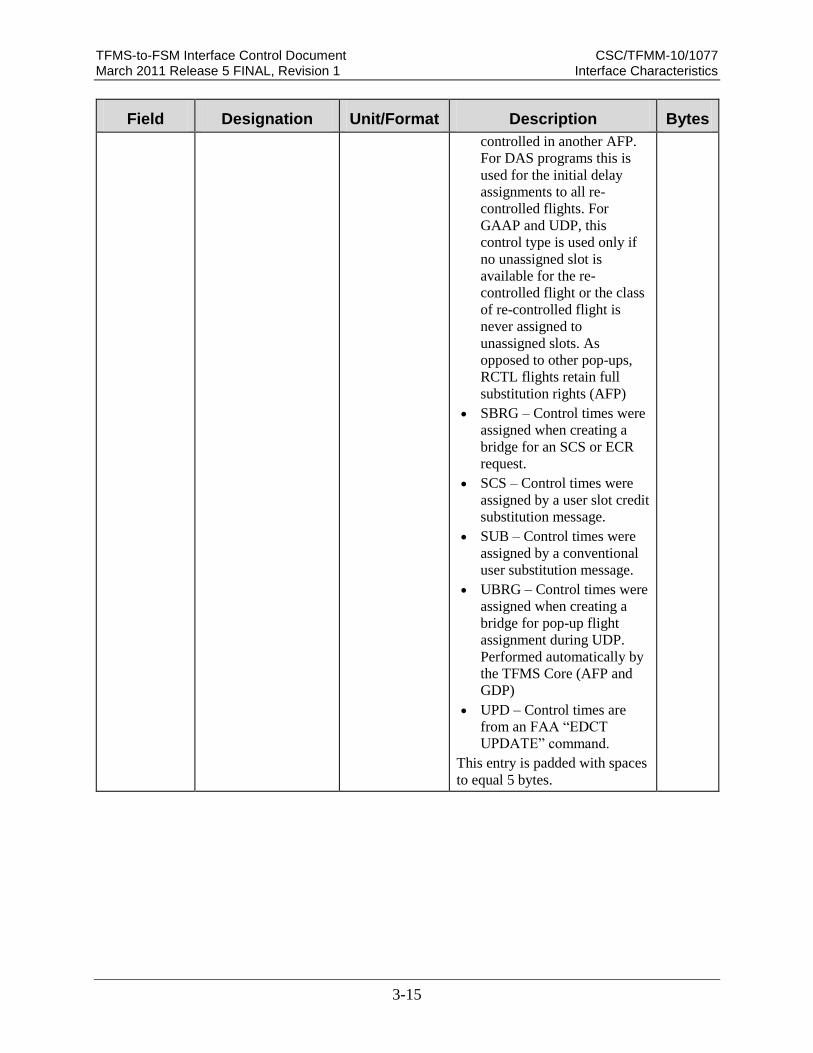
TFMS-to-FSM Interface Control Document CSC/TFMM-10/1077 March 2011 Release 5 FINAL, Revision 1 Interface Characteristics
3-15
Field Designation Unit/Format Description Bytes
controlled in another AFP.
For DAS programs this is
used for the initial delay
assignments to all re-
controlled flights. For
GAAP and UDP, this
control type is used only if
no unassigned slot is
available for the re-
controlled flight or the class
of re-controlled flight is
never assigned to
unassigned slots. As
opposed to other pop-ups,
RCTL flights retain full
substitution rights (AFP)
SBRG – Control times were
assigned when creating a
bridge for an SCS or ECR
request.
SCS – Control times were
assigned by a user slot credit
substitution message.
SUB – Control times were
assigned by a conventional
user substitution message.
UBRG – Control times were
assigned when creating a
bridge for pop-up flight
assignment during UDP.
Performed automatically by
the TFMS Core (AFP and
GDP)
UPD – Control times are
from an FAA “EDCT
UPDATE” command.
This entry is padded with spaces
to equal 5 bytes.

TFMS-to-FSM Interface Control Document CSC/TFMM-10/1077 March 2011 Release 5 FINAL, Revision 1 Interface Characteristics
3-16
Field Designation Unit/Format Description Bytes
EX Exempt Flag Y
or
–
Flag indicating flight was
exempt from delays when the
GDP or AFP was computed.
(one of two entries):
Y if true
- if False
This entry is padded with spaces
to equal 3 bytes
3
CX Cancel Flag Y
or
–
Flag indicating whether the
flight is currently cancelled.
(one of two entries):
Y if true
- if False
This entry is padded with spaces
to equal 3 bytes
3
SH Slot Hold Flag Y
or
–
Flag indicating whether the
flight is currently on Slot Hold.
(one of two entries):
Y if true
- if False
This entry is padded with spaces
to equal 3 bytes
3

TFMS-to-FSM Interface Control Document CSC/TFMM-10/1077 March 2011 Release 5 FINAL, Revision 1 Interface Characteristics
3-17
Field Designation Unit/Format Description Bytes
ERTA for a
GDP
or
EENTRY for
an AFP
Earliest Runway
Time of Arrival
Earliest Entry Time
dddddd The earliest time flight can
arrive at the controlled element
in the case that the delays are
reduced (e.g., 260200). In the
format DDhhmm, padded with
spaces to equal 7 bytes
EENTRY is used to ensure that
a flight will not be assigned a
slot for an AFP that it cannot
use. Since the CDM Participants
do not send earliest entry times
for an FCA, TFMS computes
this by: first determining the
earliest ETA (EETA), then
applying any delta to the
ENTRY time.
If flight has ERTD,
EENTRY = ENTRY +
(ERTD-ETD)
Else if flight has LRTD,
EENTRY = ENTRY +
(LRTD-ETD)
Else if flight has LGTD,
EENTRY = ENTRY +
((LGTD+10)-ETD)
Else if flight has IGTD,
EENTRY = ENTRY +
((IGTD+10)-ETD)
Else, EENTRY = ENTRY
6
IGTD Initial Gate Time of
Departure
dddddd The original scheduled gate
push back time for the flight in
the format DDhhmm. Used to
uniquely identify the flight.
6
*Note – There may be multiple rows of data under the header.
3.2.1.3.2.7 Substitution Error Responses
If errors are detected in the SS packet, the entire packet is rejected and the FAA
database is not updated. The response includes the packet identifier, a message
indicating it was rejected, and the number of errors. For each error, the response
shows the SS message that triggered the error and the reason for the error. (For a
complete listing of Error messages, refer to Table 3-IV.)

TFMS-to-FSM Interface Control Document CSC/TFMM-10/1077 March 2011 Release 5 FINAL, Revision 1 Interface Characteristics
3-18
Sample Error Response
(Line Numbers for Reference Only)
(1) SS ABC0625121029.01 REJECTED. 1 ERROR.
(2)
(3) SCS UNA1277 DFW SFO 03241701 FCAA02.242040A 242050 242140
(4) ERR417: CTA NOT WITHIN 20-MINUTE WINDOW
The meaning of the sample response is as follows:
Line 1: Shows the identifier of the packet that is being replied to. The word
“REJECTED” indicates that the processing of the packet was successful. The number
of errors is shown.
Line 2: blank
Line 3: The SS message that triggered the error.
Line 4: The error code and message. In this case, it was Error 417, indicating the
flight specified on an ECR message could not be updated in the TFMS database, due
to the fact that the CTA was not within the 20-minute window for slot times.
Table 3-IV. Error Code Messages
Number Error Description Corrective Action
Packet Header Error Messages
ERR401 PACKET NOT PROCESSED The packet has not been processed due to internal
TFMS error.
ERR402 PACKET ID IS MISSING. USE
LLLDDDDDDDDDD.DD
The packet header line does not include a packet
ID.
ERR403 INVALID PACKET ID. USE
LLLDDDDDDDDDD.DD
The packet ID does not match the specified
syntax.
ERR405 UNKNOWN PACKET CODE. USE FD
OR SS
The packet contains a code other than FD in the
header line.
ERR406 PACKET CODE LINE MISSING. USE
FD LLLDDDDDDDDDD.DD
The packet has no header line.
ERR407 UNKNOWN HUB SITE ARINC
ADDRESS. USE QU BOSCDYA
The packet was sent to the wrong address.
ERR408 PACKET NOT PROCESSED An error occurred while attempting to update the
TFMS Flight Database (FDB).
ERR409 MESSAGE NOT PROCESSED DUE TO
TFMS INTERNAL ERROR
An error occurred while attempting to update the
TFMS Flight Database (FDB).
ERR410 INVALID EN ROUTE TIME En Route Time may not exceed 18 hours.
ERR411 MESSAGE NOT PROCESSED: FDB IN
SLAVE MODE.
This message should only appear on internal
TFMS logs.
Slot Credit Substitution Error Messages
ERR412 ILLEGAL HOLD FLAG VALUE: USE
R OR H
Valid values for Hold Flag are H to hold slot or R
to release slot.

TFMS-to-FSM Interface Control Document CSC/TFMM-10/1077 March 2011 Release 5 FINAL, Revision 1 Interface Characteristics
3-19
Number Error Description Corrective Action
ERR414 NOT AUTHORIZED TO SUB FOR
THESE FLIGHTS
At least one flight in this packet belongs to a
carrier for which the sender is not authorized to
make substitutions at this airport. Sender must be
authorized to submit substitutions for all flights
referenced in an SS packet.
ERR415 CANNOT CANCEL A NON-
CONTROLLED FLIGHT
An FX message submitted in an SS packet must
pertain to a controlled flight. A non-controlled
flight may only be cancelled in an FD packet.
The most common cause for this error is an
incorrect flight ID, origin, destination, or original
gate departure date and time.
ERR417 CTA NOT WITHIN 20-MINUTE
WINDOW
CTA must be no earlier than the slot time for the
flight’s assigned slot, and no more than 20
minutes later than the slot time.
ERR418 CANNOT SUB INTO SLOT NOT
OWNED BY THIS CARRIER
The FM message references a slot that does not
currently belong to the sending airline or one of
its authorized affiliates.
ERR419 CANNOT SUB TWO FLIGHTS IN ONE
SLOT
Packet contains FM messages that assign more
than one flight to the same slot. Only one flight
may be assigned to a slot.
ERR420 CANNOT SUB ONE FLIGHT IN TWO
SLOTS
Packet contains FM messages that assign a flight
to more than one slot. A flight may be assigned to
only one slot.
ERR421 CANNOT SUB A NON-CONTROLLED
FLIGHT
Cannot use an FM message to assign a flight to a
slot if the flight does not already have a slot
assignment. This message is generated if the
flight referenced in an FM does not exist in the
TFMS flight database, or if it exists but is not
currently controlled. The most common cause is
an incorrect flight ID, origin, destination, or
original gate departure date and time.
ERR422 CANNOT CONTROL FLIGHT
SCHEDULED TO ARRIVE DURING
GDP
An SC message can be used to create a slot and
assign it to a flight only if the flight is scheduled
to arrive after the GDP end time is over.
ERR423 SLOT NOT OWNED BY FLIGHT IN
THIS PACKET
In order to preserve the one-flight-one-slot rule,
every slot that is assigned in an SS packet must
be assigned to another flight in that packet prior
to the packet being processed.
ERR424 CANNOT SUB INTO SLOT
OCCUPIED BY FORMER POP-UP
FLIGHT
Flight cannot be assigned to an earlier slot if the
flight currently assigned to that slot was formerly
a pop-up.
ERR425 AIRPORT NOT CONTROLLED A HOLD ALL SLOTS or RELEASE ALL
SLOTS message was received for an airport that
does not currently have a GDP.
ERR426 CANNOT CHANGE HOLD FLAG FOR
NON-CANCELLED FLIGHT
Cannot modify hold flag for flight that does not
have an assigned slot in a GDP. The most
common cause for this error is an incorrect flight
ID, origin, destination, or original gate departure
date and time.

TFMS-to-FSM Interface Control Document CSC/TFMM-10/1077 March 2011 Release 5 FINAL, Revision 1 Interface Characteristics
3-20
Number Error Description Corrective Action
ERR427 CANNOT SUB POP-UP FLIGHT Cannot assign a pop-up flight to a slot. Only a
revision may assign a pop-up to a slot, after
which the flight is referred to as a former pop-up.
ERR428 CONTROL INFO MISSING. SPECIFY:
DEP.TIME, ARR.TIME, AND SLOT
CTD, CTA, and ASLOT fields are required in an
FM message submitted in an SS packet.
ERR429 SLOT TIME CANNOT BE IN THE
PAST
A flight cannot be assigned to a slot whose slot
time is earlier than the current time.
ERR430 CANNOT SUB COMPLETED FLIGHT Cannot modify slot assignment for a completed
flight.
ERR431 CANNOT SUB MULTIPLE AIRPORTS All messages in an SS packet must pertain to
flights arriving at the same airport.
ERR432 CANNOT SEND FC MESSAGE IN SS
PACKET
Flights cannot be created in an SS packet. An FC
message may only be submitted in an FD packet.
ERR433 SC CAN BE SENT ONLY IN SS
PACKET
Slots cannot be created in an FD packet. An SC
message may only be submitted in an SS packet.
ERR434 CANNOT CREATE SLOT FOR
CONTROLLED FLIGHT
Flight referenced in SC message is already
controlled. Cannot use SC message to create a
slot and assign a flight to the newly created slot if
the flight already has an assigned slot or an FA
Delay.
ERR435 SLOT ALREADY EXISTS The slot value provided in SC message already
exists. A newly created slot must have a unique
slot identifier. An airline can generally create a
unique identifier by changing the suffix letter in
the slot name.
ERR436 INVALID MESSAGE TYPE FOR SS
PACKET. USE FM/FX/SCS/HOLD ALL
SLOTS/RELEASE ALL SLOTS
Only FM, FX, SCS, HOLD ALL SLOTS or
RELEASE ALL SLOTS are valid within an SS
packet.
ERR437 SLOT IN SC MSG CANNOT BE
DURING CURRENT GDP
Slot time for newly created slot falls in the
current GDP timeframe. For an airline to create a
slot, the slot time portion of the “Assigned
Arrival Slot” field in the SC message must
specify a time that is after the GDP is over.
ERR438 CANNOT SUB REMOVED FLIGHT The flight has been removed by the FAA and is
not available for subbing.
ERR439 ETE CANNOT BE CHANGED BY
MORE THAN 50%
The new ETE, derived by subtracting CTD from
CTA, cannot change from the prior ETE by more
than 45 minutes or 50% of the prior ETE,
whichever is greater.
ERR440 SUB PROCESSING IS OFF Command Center is currently not accepting
substitution messages pertaining to this GDP.
TFMS sends an TFMS SUBS ON message when
it resumes accepting substitution messages
ERR441 SCS CAN ONLY BE INCLUDED IN SS
PACKETS
A Slot Credit Sub message can only be included
in an SS packet, not in an FD or EI packet.

TFMS-to-FSM Interface Control Document CSC/TFMM-10/1077 March 2011 Release 5 FINAL, Revision 1 Interface Characteristics
3-21
Number Error Description Corrective Action
ERR442 SCS PROCESSING IS OFF The FAA has turned Slot Credit Sub processing
off for the airport. All SCS requests will be
rejected.
ERR443 YIELDED SLOT MUST BE IN THE
FUTURE
The slot that is being given up in the SCS
message must be later than the current time.
ERR444 EARLIEST ACCEPTABLE TIME
MUST BE LATER THAN TIME OF
YIELDED SLOT
The time of the yielded slot must be earlier than
the earliest acceptable time.
ERR445 EARLIEST ACCEPTABLE TIME
MUST BE EARLIER THAN LATEST
ACCEPTABLE TIME
The window of acceptable times must be
specified as the earliest acceptable time first then
the latest acceptable time.
ERR446 20-MINUTE WINDOW NOT
ALLOWED WITH SCS
The substitution window size for an SCS packet
must be set to 0. If any flights within the packet
violate the window size, then the packet will be
rejected.
ERR447 YIELDED SLOT OWNED BY
FORMER POP-UP FLIGHT
The yielded slot must not be owned by a former
pop-up.
ERR448 SCS TIME RANGES OVERLAP The time ranges of different SCS messages
within a packet must not overlap. The time range
of an SCS is defined as the time from the yielded
slot to the latest acceptable time.
ERR449 SLOT CREDIT SUBSTITUTION
CANNOT BE FULFILLED
No bridge flights could be found that would
allow the SCS flight to be moved into the
requested window.
ERR450 SLOT TIME OF SCS FLIGHT IS
ALREADY WITHIN WINDOW
The yielded slot of the SCS flight already falls
within the requested window. No processing is
required.
ERR451 SCS PROCESSING HAS BEEN
DISABLED UNTIL FURTHER NOTICE
The FAA has suspended SCS processing
temporarily.
3.2.1.3.2.8 EDCT and Other Commands
In general, EDCT commands are associated with the management of delay programs.
There are two basic categories of commands, commands that request data (i.e,
reports) and commands that change data. Most of the EDCT commands can be
entered from both the TFMS TSD and the FSM client. Also, most of these
commands are only available to FAA authorized users. This ICD documents those
EDCT commands entered via FSM, which result in a data exchange between FSM
and TFMS. The format of the command entered by a user is the same regardless of
whether it is entered from a TSD or FSM. However, when an EDCT command is
entered from FSM, the command is sent to the TFMS, where the data associated with
the command can be changed (with the change acknowledged) or provided back to
the requestor in the form of a report. The available EDCT commands related to FSM
are as follows:

TFMS-to-FSM Interface Control Document CSC/TFMM-10/1077 March 2011 Release 5 FINAL, Revision 1 Interface Characteristics
3-22
EDCT AC OFF
EDCT AC ON
EDCT CHECK
EDCT CNX
EDCT CTALIST
EDCT HOLD
EDCT LIST (report request)
EDCT LOG
EDCT PURGE
EDCT RELEASE
EDCT REMOVE
EDCT RESTORE
EDCT SCS OFF
EDCT SCS ON
EDCT SHOW
EDCT SLIST (report request)
EDCT SLOTS
EDCT SUB OFF
EDCT SUB ON
EDCT
EDCT SUB SHOW (report
request)
EDCT UNASSIGNED SLOTS
(report request)
EDCT UPDATE
These commands are documented in the ETMS Reference Manual Volumes I and II
(refer to Section 2.1) for full references. The commands are also briefly described in
Appendix A of this ICD. The mechanisms used to send these commands and their
corresponding replies between TFMS and FSM are the protocol messages, which are
documented in Section 3.2.2.1, Application Services.
The following additional commands are available to the FSM user, which result in a
data exchange on the TFMS – FSM interface:
Weather Request – used to request current airport weather (METAR and TAF)
for one or more airports (uses the three letter airport identifiers separated by
commas or spaces)
ADL Request – used to request a new ADL for a specific airport or FSM-eligible
FEA/FSM.
ADL AAR – used to reset an Arrival Rate to its default or to modify ADL
Arrival Rates for an airport or FSM eligible FEA/FCAADL
ADR - used to reset a Departure Rate to its default or to modify ADL Departure
Rates for an airport
Delete Program Parameters – used to delete delay program parameters for a
specific airport or Flow Constrained Area (FCA).
These commands are documented in the ETMS Reference Manual Vol. II (refer to
Section 2.1) for full reference. The commands are also briefly described in Appendix
A of this ICD. The mechanisms used to send these commands and their
corresponding replies between TFMS and FSM are the protocol messages, which are

TFMS-to-FSM Interface Control Document CSC/TFMM-10/1077 March 2011 Release 5 FINAL, Revision 1 Interface Characteristics
3-23
documented in Appendix D, CDM Message Protocol.
NAS Users can make requests for data as well as requests that control aspects of
substitution process. Four reports are available to the NAS Users. These reports
apply to FCAs, AFPs as well as airports GDPs:
EDCT Report Requests
A sample report request has the following format:
Sample EDCT Report Request
(Line Numbers for Reference Only)
(1) EDCT LIST
(2) EDCT SUB SHOW
(3) EDCT SLIST
(4) EDCT UNASSIGNED SLOTS
Table 3-V below presents a breakout of the EDCT Report Request. Sections
3.2.1.3.2.9 through 3.2.1.3.2.12 describe the format of each of the report response
messages.
Table 3-V. Report Request
Field/Line Designation Unit/Format Description Bytes
Line 1-n: Request(s). The packet can include one or more requests. Each requested report comes back
as a separate message. Possible request types are listed below
1 EDCT LIST EDCT LIST Returns a list of all airports that
currently have GDPs. (See
3.2.1.3.2.15 below)
9
2 EDCT SUB SHOW EDCT SUB
SHOW
Returns the substitution status
(on or off) at all airports that
currently have GDPs (sub
status is also part of the EDCT
LIST report) (See 3.2.1.3.2.16
below)
13
3 EDCT SLIST EDCT SLIST
aaa [aaa]…[aaa]
Returns a slot list for the
requested airport. Unlike the
slot lists when the GDP is
issued, the EDCT SLIST report
returns a single list that
includes all flights affiliated
with the requesting airline. That
is, the reply can include
15-68

TFMS-to-FSM Interface Control Document CSC/TFMM-10/1077 March 2011 Release 5 FINAL, Revision 1 Interface Characteristics
3-24
Field/Line Designation Unit/Format Description Bytes
different 3-letter airline codes
in one report
4 EDCT
UNASSIGNED
SLOTS
EDCT
UNASSIGNED
SLOTS
Returns a list of unassigned
slots, similar to the ADL
UNNASSIGNED_SLOTS
block
21
3.2.1.3.2.9 EDCT LIST
This message returns a list of all airports that currently have GDPs. A sample EDCT
LIST has the following format:
Sample EDCT LIST
(Line Numbers for Reference Only)
(1) Number of airports currently controlled: 3
(2)
(3) DEST TIMES CONTROL FLIGHTS SUBS SCS AC
(4) ---------------------------------------------------------
(5) EWR /19/01/ EDCT+DAS 255 ON ON ON
(6) JFK /20/23/ GS 47 OFF OFF ON
(7)
(8) Bridging status at EWR:
(9) - Carriers which turned bridging OFF:
(10) USA
(11) Bridging status at JFK: ON.
(12)
(13) Number of FCAs currently controlled: 1
(14)
(15) FCA TIMES CONTROL FLIGHTS SUBS SCS AC
(16) ---------------------------------------------------------
(17) FCAA02 /18/23/ EDCT+DAS 24 ON ON OFF
(18)
(19) Bridging status at FCAA02: ON.
(20)

TFMS-to-FSM Interface Control Document CSC/TFMM-10/1077 March 2011 Release 5 FINAL, Revision 1 Interface Characteristics
3-25
(21) Bridging turned OFF permanently for non-CDM general aviation
and military.
(22)
(23) Printer: $fsa.//wkstn32
Table 3-VI below presents a breakout of the EDCT List
Table 3-VI. EDCT List
Field/Line Designation Unit/Format Description Bytes
1 Number of
Controlled Airports NUMBER OF
AIRPORTS
CURRENTLY
CONTROLLE
D: d[d]
The number of airports that
currently have GDPs or GSs.
42-43
2 Blank Line Separator Blank line separating data 1
3 Headers DEST
TIMES
CONTROL
FLIGHTS
SUBS SCS
AC
Column Headers:
DEST – Destination Airport
TIMES – GDP/GS Time
range
CONTROL – Type of
Control issued
FLIGHTS – Number
affected
SUBS – Substitution Status
SCS - Slot Credit
Substitutions Status
AC – Adaptive
Compression Status
49
4 Dashed Line
Separator -------------------
------------------
Dashed line separator 49
5 Destination Laa[a] Destination airport in three or
four character identifier. This
entry is padded with spaces to
equal 8 bytes.
8
5 Times /dd/dd Start and end times of the GDP
or ground stop in the following
format: /hh/hh (hour start and
hour end in sequence)
This entry is padded with spaces
to equal 9 bytes.
9
5 Control LL[LL…LLL] Control Type issue: May be
more than one entry. If so, each
entry will be joined by a plus
12

TFMS-to-FSM Interface Control Document CSC/TFMM-10/1077 March 2011 Release 5 FINAL, Revision 1 Interface Characteristics
3-26
Field/Line Designation Unit/Format Description Bytes
sign. This entry is padded with
spaces to equal 12 bytes.
5 Flights d[d][d][d] Number of flights that are
affected by the Control. In as
many digits are necessary to
detail. This entry is padded with
spaces to equal 10 bytes.
10
5 Sub Status ON
or
OFF
Status of substitutions: One of
two entries:
ON
OFF
This entry is padded with spaces
to equal 7 bytes.
7
5 SCS Status ON
or
OFF
Status of Slot Credit
Substitutions. One of two
entries:
ON
OFF
2-3
5 AC ON
or
OFF
Adaptive Compression Status.
One of two entries:
YES
NO
2-3
6 – #n Multiple entries are possible
containing the items listed as
Field/Line 5.
48-49
per line
7 Blank Line Separator Blank line separating data 1
8 Bridging Status BRIDGING
STATUS AT
Laa:
Status of bridging for individual
GDPs.
23
9 Bridging Off - CARRIERS
WHICH
TURNED
BRIDGING
OFF:
If bridging is off, the report lists
each carrier that currently has
bridging off for that GDP. This
field is led by two blank spaces.
39
10 Carrier List LLL [LLL] Carriers which have turned
Bridging off. This field is led by
4 blank spaces.
3-68
11 Bridging Status BRIDGING
STATUS AT
Laa: ON
Status of bridging for individual
GDPs, indicating Bridging is
ON.
28
12 Blank Line Separator Blank line separating data 1

TFMS-to-FSM Interface Control Document CSC/TFMM-10/1077 March 2011 Release 5 FINAL, Revision 1 Interface Characteristics
3-27
Field/Line Designation Unit/Format Description Bytes
13 Number of
Controlled FCAs NUMBER OF
FCAS
CURRENTLY
CONTROLLE
D: d[d]
Number of controlled FCAs. In
one or two digits
38-39
14 Blank Line Separator Blank line separating data 1
15 Headers FCA TIMES
CONTROL
FLIGHTS
SUBS SCS
AC
Column Headers:
FCA – FCA Identifier
TIMES – GDP/GS Time
range
CONTROL – Type of
Control issued
FLIGHTS – Number
affected
SUBS – Substitution Status
SCS - Slot Credit
Substitutions Status
AC – Adaptive
Compression Status
49
16 Dashed Line
Separator -------------------
-------------------
Dashed line separator 49
17 FCA Identifier FCAaaa FCA in six character identifier.
This entry is padded with spaces
to equal 8 bytes.
8
17 Times /dd/dd Start and end times of the GDP
or ground stop in the following
format: /hh/hh (hour start and
hour end in sequence)
This entry is padded with spaces
to equal 9 bytes.
9
17 Control LL[LL…LLL] Control Type issue: May be
more than one entry. If so, each
entry will be joined by a plus
sign. This entry is padded with
spaces to equal 12 bytes.
12
17 Flights d[d][d][d] Number of flights that are
affected by the Control. In as
many digits are necessary to
detail. This entry is padded with
spaces to equal 10 bytes.
10
17 Sub Status ON
or
OFF
Status of substitutions: One of
two entries:
ON
OFF
7

TFMS-to-FSM Interface Control Document CSC/TFMM-10/1077 March 2011 Release 5 FINAL, Revision 1 Interface Characteristics
3-28
Field/Line Designation Unit/Format Description Bytes
This entry is padded with spaces
to equal 7 bytes.
17 SCS Status ON
or
OFF
Status of Slot Credit
Substitutions. One of two
entries:
ON
OFF
2-3
17 AC Status ON
or
OFF
Adaptive Compression Status.
One of two entries:
On
Off
2-3
17– #n Multiple entries are possible
containing the items listed as
Field/Line 17.
48-49
per line
18 Blank Line Separator Blank line separating data 1
19 Bridging Status BRIDGING
STATUS AT
FCAaaa: ON
Status of bridging for individual
AFPs.. Same format as for
GDPs
23
20 Blank Line Separator Blank line separating data 1
21 System Bridging
Status BRIDGING
TURNED OFF
PERMANENT
LY FOR
NON-CDM
GENERAL
AVIATION
AND
MILITARY.
Status of bridging for the
system. This applies to both
GDPs and AFPs. (NOTE: This
line continues out past the right
margin.)
74
22 Blank Line Separator Blank line separating data 1
23 Printer PRINTER:
aaaa./aaaaaaaa
Location of the printer at the
command center. (NOTE: This
is of no use for the NAS user.)
24
3.2.1.3.2.10 EDCT SUB SHOW
This message returns the substitution status (on or off) at all airports that currently
have GDPs (sub status is also part of the EDCT LIST report) as well as the
substitution status for all FCAs that have AFPs. A sample EDCT SUB SHOW report
has the following format:

TFMS-to-FSM Interface Control Document CSC/TFMM-10/1077 March 2011 Release 5 FINAL, Revision 1 Interface Characteristics
3-29
Sample EDCT SUB SHOW
(Line Numbers for Reference Only)
(1) Current Time: 18:06:17 on 7/29/2005
(2)
(3) Airport SUB Processing Activated SCS Processing Activated AC Active
(4) -----------------------------------------------------------------
(5) EWR Yes Yes Yes
(6) JFK No No No
(7)
(8) Bridging status at EWR:
(9) - Carriers which turned bridging OFF:
(10) USA
(11) Bridging status at JFK: ON.
(12)
(13) FCA SUB Processing Activated SCS Processing Activated AC Active
(14) -----------------------------------------------------------------
(15) FCAA02 Yes Yes No
(16)
(17) Bridging status at FCAA02: ON.
(18)
(19) Bridging turned OFF permanently for non-CDM general aviation …
(20)
(21) Printer: $fsa.//wkstn32
Table 3-VII below presents a breakout of the EDCT Sub Show
Table 3-VII. EDCT Sub Show
Field/Line Designation Unit/Format Description Bytes
1 Current Time and
Date CURRENT
TIME:
dd:dd:dd ON
d[d]/d[d]/dddd
Current Time and Date of
message in format hh:mm:ss on
M[M]/D[D]/YYYY
hh – hour
mm – minute
40

TFMS-to-FSM Interface Control Document CSC/TFMM-10/1077 March 2011 Release 5 FINAL, Revision 1 Interface Characteristics
3-30
Field/Line Designation Unit/Format Description Bytes
ss – second
M[M] – Month in one or
two digits
D[D] – day in one or two
digits
YYYY – Year
2 Blank Line Separator Blank line separating data 1
3 GDP Headers AIRPORT
SUB
PROCESSING
ACTIVATED
SCS
PROCESSING
ACTIVATED
AC
ACTIVATED
Column Headers:
Airport – Destination
Airport
Sub Processing Activated–
Substitution Processing on
or off
SCS Processing Activated –
Slot Control Substitution
Processing on or off
Adaptive Compression
Activated on or off
59
4 Dashed Line
Separator -------------------
-------------------
Dashed line separator 49
5 Airport Laa[a] Destination airport in three or
four character identifier. This
entry is padded with spaces to
equal 11 bytes.
11
5 Sub Processing YES
or
NO
Substitution Processing Status.
One of two entries:
YES
NO
This entry is padded with spaces
to equal 26 bytes.
26

TFMS-to-FSM Interface Control Document CSC/TFMM-10/1077 March 2011 Release 5 FINAL, Revision 1 Interface Characteristics
3-31
Field/Line Designation Unit/Format Description Bytes
5 SCS Processing YES
or
NO
Substitution Processing Status.
One of two entries:
YES
NO
2-3
5 AC Activated YES
or
NO
Adaptive Compression Status.
One of two entries:
YES
NO
2-3
6 – #n Multiple entries are possible
containing the items listed as
Field/Line 5.
48-49
per line
7 Blank Line Separator Blank line separating data 1
8 Bridging Status BRIDGING
STATUS AT
Laa:
Status of bridging for individual
GDPs. 23
9 Bridging Off - CARRIERS
WHICH
TURNED
BRIDGING
OFF:
If bridging is off, the report lists
each carrier that currently has
bridging off for that GDP. This
field is led by two blank spaces.
39
10 Carrier List LLL [LLL] Carriers which have turned
Bridging off. This field is led by
4 blank spaces.
3-68
11 Bridging Status BRIDGING
STATUS AT
Laa: ON
Status of bridging for individual
GDPs, indicating Bridging is
ON.
28
12 Blank Line Separator Blank line separating data 1
13 FCA Header FCA
SUB
PROCESSING
ACTIVATED
SCS
PROCESSING
Column Headers:
FCA – FCA Number
Sub Processing Activated–
Sub Processing on or off
SCS Processing Activated –
Slot Control Substitution
processing on or off
59

TFMS-to-FSM Interface Control Document CSC/TFMM-10/1077 March 2011 Release 5 FINAL, Revision 1 Interface Characteristics
3-32
Field/Line Designation Unit/Format Description Bytes
ACTIVATED
AC
ACTIVATED
Adaptive Compression
Activated on or off
14 Dashed Line
Separator -------------------
-------------------
-----------
Dashed line separator 49
15 FCA Identifier FCAaaa FCA in six character identifier.
This entry is padded with spaces
to equal 8 bytes.
8
15 Sub Processing YES
or
NO
Substitution Processing Status.
One of two entries:
YES
NO
This entry is padded with spaces
to equal 26 bytes.
26
15 SCS Processing YES
or
NO
Substitution Processing Status.
One of two entries:
YES
NO
2-3
15 AC Active Yes
or
No
Adaptive Compression Status.
One of two entries:
YES
NO
2-3
15– #n Multiple entries are possible
containing the items listed as
Field/Line 17.
48-49
per line
16 Blank Line Separator Blank line separating data 1
17 Bridging Status BRIDGING
STATUS AT
FCAaaa: ON
Status of bridging for individual
AFPs. Same format as for
GDPs.
23
18 Blank Line Separator Blank line separating data 1
19 System Bridging
Status BRIDGING
TURNED OFF
PERMANENT
Status of bridging for the
system. This applies to both
GDPs and AFPs. (NOTE: This
line continues out past the right
74

TFMS-to-FSM Interface Control Document CSC/TFMM-10/1077 March 2011 Release 5 FINAL, Revision 1 Interface Characteristics
3-33
Field/Line Designation Unit/Format Description Bytes
LY FOR
NON-CDM
GENERAL
AVIATION
AND
MILITARY.
margin.)
20 Blank Line Separator Blank line separating data 1
21 Printer PRINTER:
aaaa./aaaaaaaa
Location of the printer at the
command center. (NOTE: This
is of no use for the NAS user.)
24
3.2.1.3.2.11 EDCT SLIST
The EDCT SLIST request returns the same format used to issue a GDP/AFP, or to
reply to an SS message. A sample EDCT SLIST report (for an AFP) has the
following format:
Sample EDCT SLIST
(Line Numbers for Reference Only)
(1) SLOT LIST FOR FCAA02
(2)
(3) ACID ASLOT DEP ARR CTD CTA TYPE EX CX SH EENTRY IGTD
(4) ABC1234 FCAA02.260400A DCA LGA 260300 260400 AFP - - - 260400 260245
ABC5678 FCAA02.260500A IAD BOS 260400 260500 AFP - - - 260300 260145
ABC360 FCAA02.260323A CYYZ LGA 260206 260323 AFP Y - - 260319 260150
ABC3522 FCAA02.260311A DCA BOS 260215 260311 AFP - - - 260311 260145
ABC39 FCAA02.260353A ROC LGA 260246 260353 AFP - Y - 260355 260235
Table 3-VIII below presents a breakout of the EDCT SLIST.

TFMS-to-FSM Interface Control Document CSC/TFMM-10/1077 March 2011 Release 5 FINAL, Revision 1 Interface Characteristics
3-34
Table 3-VIII. EDCT SLIST
Field/Line Designation Unit/Format Description Bytes
1 Slot List Identifier SLOT LIST
FOR FCAaaa
or
SLOT LIST
FOR aaa
Identifies airport or FCA that the
slot list is for.
17-20
2 Blank Line Separator Blank line separating data 1
3 Slot List Data
Headers
ACID
ASLOT
DEP ARR
CTD CTA
TYPE EX CX
SH
EENTRY (or)
ERTA
IGTD
Header for the following Slot
List data fields:
ACID – Aircraft identifier
ASLOT – Arrival Slot
DEP – Departure Airport
ARR – Arrival Airport
CTD – Controlled Time of
Departure
CTA –Controlled Time of
Arrival
TYPE – Type of Entry
EX – Exempt Flag (Yes or
No)
CX – Control Flag (Yes or
No)
SH – Slot Hold flag (Yes or
No)
EENTRY – Earliest Entry
Time (for AFP)
or
ERTA - Earliest Runway
Time of Arrival (for Airport
GDP)
IGTD - Initial Gate Time of
Departure
64
4 - n Slot List Data Fields
Refer to Table 3-III for detailed
breakout.
*Note – There may be multiple rows of data under the header.

TFMS-to-FSM Interface Control Document CSC/TFMM-10/1077 March 2011 Release 5 FINAL, Revision 1 Interface Characteristics
3-35
3.2.1.3.2.12 EDCT UNASSIGNED SLOTS
The EDCT UNASSIGNED SLOTS will contain a list of unassigned slots that have
not yet been allocated to flights. An example is provided below, followed by a
detailed breakout in Table 3-IX.
Sample Unassigned Slots Blocks
(1) EDCT UNASSIGNED SLOTS
(2)
(3) EWR.191233A EWR.191234A EWR.191235A EWR.191236A EWR.191237A EWR.191238A
(4) EWR.191241A EWR.191242A EWR.191243A EWR.191442A EWR.191245A EWR.191246A
(5) EWR.191249A EWR.191250A EWR.191251A EWR.191252A EWR.191253A EWR.191254A
(1) EDCT UNASSIGNED SLOTS
(2)
(3) FCA027.191233A FCA027.191234A FCA027.191235A FCA027.191236A FCA027.191237A
(4) FCA027.191241A FCA027.191242A FCA027.191243A FCA027.191442A FCA027.191245A
(5) FCA027.191249A FCA027.191250A FCA027.191251A FCA027.191252A FCA027.191253A
Table 3-IX. EDCT UNASSIGNED SLOTS
Line Function Unit/Format Description Bytes
1 Unassigned Slots
title
EDCT
UNASSIGNED
SLOTS
Static Entry: EDCT
UNASSIGNED SLOTS 21
2 Blank Line
Blank Line Separator 1
3-n
Unassigned Slot
entries
LLL.dddddda
(GDP)
or
FCAaaa.dddddda
(AFP)
or
NONE
(Empty)
The block contains a list of
unassigned slots that have not
yet been allocated to flights.
Two different entries are used:
GDP – The formatting for
GDP is
Airport Name – three
letters
Slot number – six digits,
followed by one
alphanumeric character.
15-75*

TFMS-to-FSM Interface Control Document CSC/TFMM-10/1077 March 2011 Release 5 FINAL, Revision 1 Interface Characteristics
3-36
Line Function Unit/Format Description Bytes
AFP – The formatting for
AFP is
FCA Identifier – three
letters FCA followed by
three alphanumeric
characters
Slot number – six digits,
followed by one
alphanumeric character.
3.2.1.3.2.13 Delay Program Rate Messages
FSM transmits Delay Program arrival and departure rates (AAR and ADR
respectively) using the messages listed below that are described in Appendix D.
Delay Program Rate Messages are received when an Actual Delay Program is
initiated. Delay Program Rate Messages are not received for Proposed Delay
Programs.
M_ADD_ADL_AAR_GDP
M_DEL_ADL_AAR_GDP
The format of the Delay Program Rate Messages is internal to FSM. TFMS treats the
Delay Program Rate Message as a simple text string that is extracted, retained and
inserted into the ADL for the associated control element. The exception to this is the
Control Element name (i.e., airport or AFP name) as well as the time. These are the
first two elements in the Delay Program Rate message. Table 3-X describes he
format of the Delay Program Rate Message.
Table 3-X. Delay Program Rate Message
Field Function Unit/Format Description Bytes
1 Control Element
Identifier
aaa or FCAaaa
or aaaaaa
The name of the airport, FEA,
or FCA to which the data rates
in this message are associated.
The alphanumeric string is
followed by a blank.
For airports – three or four
alpha-mumeric character
airport identifier
For FEAs – up to six
characters limited to upper
case alpha-numeric, “-“, and
“_”. Characters may be used
in any position except that “-
5-7

TFMS-to-FSM Interface Control Document CSC/TFMM-10/1077 March 2011 Release 5 FINAL, Revision 1 Interface Characteristics
3-37
Field Function Unit/Format Description Bytes
“, and “_” may not be used in
the last position. NOTES -
FEA names are not
guaranteed to be unique and
can duplicate airport names,
in such a case they should not
be considered to be the same
element. FEA names can be
reused within the same day,
in such a case they should not
be considered to be the same
element.
For FCAs - six alpha-numeric
characters beginning with
“FCA”.
2 Time dddddddd Date and time expressed as
DDHHMMSS. Often referred to
as the “FADT Report Time”. 8
digits of time are followed by a
blank.
9
3 Aircraft Arrival (or
Departure) Rate
Time and
Incremental Rates
AAR_TIME
dddddd IDX
d[d] AAR-d[d]
[ddx20] or
ADR_TIME
dddddd IDX
d[d] ADR-d[d]
[ddx20]
The AAR_TIME (or
ADR_TIME) value consists of
three entries:
The date/time of the first 15
minute period to which the
first AAR (or ADR) should
be applied. Format is
ddhhmm.
The code “IDX ddd” is for
uses other than TFMS and is
ignored.
The remaining AARs (or
ADRs) are for the subsequent
15 minute periods after the
start date/time, in one or two
digits.
27-87*
Note – The maximum stated here is for a single data line. There may be multiple lines of
data as necessary.
3.2.1.3.2.14 Delay Program Parameters Messages
FSM notifies TFMS of delay program parameters for GDPs, AFPs, and GSs using
the following messages that are described in Appendix D. Delay Program Parameter
Messages are received for both Proposed and Actual Delay Programs. There is a
separate message for original program parameters as well as separate parameters for

TFMS-to-FSM Interface Control Document CSC/TFMM-10/1077 March 2011 Release 5 FINAL, Revision 1 Interface Characteristics
3-38
compression and blanket revisions to an existing delay program.
M_ADD_ADL_GDP_PARAM
M_ADD_ADL_COMP_PAPAM
M_ADD_ADL_BLANK_PARAM
M_ADD_ADL_GS_PARAM
M_ADD_ADL_AFP_PARAM
M_DEL_ADL_GDP_PARAM
M_DEL_ADL_COMP_PAPAM
M_DEL_ADL_BLANK_PARAM
M_DEL_ADL_GS_PARAM
M_DEL_ADL_AFP_PARAM
See Appendix C FSM ADL Parameters Specification for a detailed description of the
individual parameters.
3.2.1.3.2.15 Heartbeat Message
Heartbeat messages are simply a brief exchange of heartbeat requests and responses
between FSM and the TFMS to indicate the system is still functional, if there has
been no message traffic between the two for a specified amount of time. It consists
of a request message (M_HB_REQ) from the FSM and a response message
(M_HB_ACK) from TFMS. FSM sends the M_HB_REQ message to TFMS,
requesting a heartbeat message to confirm that the connection is still active. TFMS
sends back the M_HB_ACK message with an acknowledgement. Appendix D
provides the record layout of these two messages.
3.2.1.3.3 Information Unit Segmentation
The TFMS-to-FSM APs are not required to perform message segmentation.
3.2.1.3.4 Direction of Information Flow
The information flow between FSM and TFMS is bi-directional. The flow of
individual messages is detailed in Table 3-V.
3.2.1.3.5 Frequency of Transmission
All message traffic in the TFMS-to-FSM interface is dynamic, with data sent when it
is required.
3.2.1.3.6 Responses
Refer to Section 3.2.2.1 for session messages and responses, detailing required
responses.
3.2.1.4 Quality of Service
Not Applicable.

TFMS-to-FSM Interface Control Document CSC/TFMM-10/1077 March 2011 Release 5 FINAL, Revision 1 Interface Characteristics
3-39
3.2.1.5 AP Error Handling
The FAA will send a response to every SS message packet, to the return address on
the incoming message. If errors are detected in the SS packet, the entire packet is
rejected. The response to the error includes the packet identifier, a message
indicating it was rejected, and the number of errors. For each error, the response
shows the SS message that triggered the error and the reason for the error. (For a
complete listing of Error messages, refer to Table 3-IV.)
Loss of FSM
TFMS will consider any of the following events to be a “loss of FSM”:
Notification that a message is undeliverable
An excessive backup in the sending queue (see below)
Receipt of a disconnect message
Loss of TFMS
FSM will consider any of the following to be a “loss of TFMS”:
Notification that the connection to the server has been lost
Notification that a message to the server is undeliverable
Receipt of a shutdown message
In addition, TFMS will queue ADL files intended for FSM in the event that the
socket is not being read as fast as it is being written. A maximum queue of 50 ADL
files will be allowed. Once the maximum is exceeded, TFMS will consider FSM to
be inaccessible and will terminate the session.
3.2.1.6 Summary Table
An interface summary table (see Table 3-XI below) shows the association between
the messages that flow across the interface and the APs of the interfacing
subsystems. The left side of the interface summary table column lists the TFMS APs.
The center columns contain the names of the messages transferred and the direction
of transfer flow. The right hand column lists the FSM APs.
Table 3-XI. TFMS-to-FSM Interface Summary
Subsystem A TFMS AP Messages
Flow Direction
Subsystem B FSM AP
FAA Portal Aggregate Demand List AB FSM Server
External Portal Aggregate Demand List AB FSM Server
FAA Portal FSM Broadcast Request AB FSM Server
External Portal FSM Broadcast Request AB FSM Server
FAA Portal FSM Broadcast Reply AB
FSM Server

TFMS-to-FSM Interface Control Document CSC/TFMM-10/1077 March 2011 Release 5 FINAL, Revision 1 Interface Characteristics
3-40
Subsystem A TFMS AP Messages
Flow Direction
Subsystem B FSM AP
External Portal FSM Broadcast Reply AB
FSM Server
FAA Portal FSM Broadcast Message AB FSM Server
External Portal FSM Broadcast Message AB FSM Server
FAA Portal EDCT Change Request Messages AB FSM Server
External Portal Slot Credit Substitution Messages AB FSM Server
FAA Portal Substitution Good Responses AB FSM Server
External Portal Substitution Good Responses AB FSM Server
FAA Portal Substitution Error Responses AB FSM Server
External Portal Substitution Error Responses AB FSM Server
FAA Portal EDCT Commands/Replies AB FSM Server
External Portal EDCT Commands/Replies (EDCT Report
Requests/Reports) AB
FSM Server
FAA Portal Delay Program Rate Messages AB FSM Server
External Portal Delay Program Rate Messages AB FSM Server
FAA Protal Delay Program Parameters Messages AB FSM Server
External Portal Delay Program Parameters Messages AB FSM Server
FAA Portal Heartbeat Message AB FSM Server
External Portal Heartbeat Message AB FSM Server
3.2.2 Protocol Implementation
The TFMS to FSM interface communications functions are implemented according
to OSI reference model as defined in FAA-STD-039b, Open Systems Architecture
and Protocols, and FAA-STD-043b, Open System Interconnect Priority.
Subsection 3.2.2 documents the OSI protocols implemented for each layer of the
interface.
a. Application Layer (Layer 7) - This layer is not implemented within the
TFMS-to-FSM interface.
b. Presentation Layer (Layer 6) – This layer is not implemented within the
TFMS-to-FSM interface.
c. Session Layer (Layer 5) - This layer is not implemented within the TFMS-to-
FSM interface.
d. Transport Layer (Layer 4) - The TFMS-to-FSM interface uses the TCP, in
accordance with RFC793, Transmission Control Protocol, Sep 1983, as its
Transport layer protocol.
e. Network (Packet) Layer (Layer 3) - The TFMS-to-FSM interface uses the
standard IP RFC791, Internet Protocol, Sep 1981, as its Network layer
protocol.

TFMS-to-FSM Interface Control Document CSC/TFMM-10/1077 March 2011 Release 5 FINAL, Revision 1 Interface Characteristics
3-41
f. Data-Link (Frame) Layer (Layer 2) – The TFMS-to-FSM uses the 100-baseT
Ethernet standard in accordance with IEEE 802.3, IEEE Standard for
Information Technology — Telecommunications and Information Exchange
Between Systems, 2000 as the Data Link Layer
g. Physical Layer (Layer 1) – The Physical layer of the TFMS-to-FSM interface
uses a standard Category 5 (Cat-5) Ethernet cable as its Physical layer
protocol.
Figure 3-2, OSI Layer Functional Interface Connectivity Diagram for TFMS-to-
FSM, gives a visual representation of the OSI layers and their structure.
TFMS FSM
APPLICATION
PRESENTATION
SESSION
TRANSPORT
NETWORK
DATA LINK
PHYSICAL
APPLICATION
PRESENTATION
SESSION
TRANSPORT
NETWORK
DATA LINK
PHYSICAL
Application
Processes
Application
Processes
Implemented by a Category 5 (Cat-5) Ethernet cable
100 base T Ethernet
IP Protocol
TCP Protocol
OSI Layer Functional Interface Connectivity Diagram for TFMS-to-FSM
Dotted lines represent standards and or protocols employed
Solid lines represent applications and / or physical connections employed
Figure 3-2. OSI Layer Functional Interface Connectivity Diagram for TFMS-to-FSM
3.2.2.1 Application Services
This section details the application and connectivity of the FSM interface. TFMS-to-
FSM interface uses CDM Session protocols and a number of other sub-protocols to
initiate and a session with the clients and exchange data. These protocols are defined
in detail in Appendix D.
3.2.2.2 Network Services

TFMS-to-FSM Interface Control Document CSC/TFMM-10/1077 March 2011 Release 5 FINAL, Revision 1 Interface Characteristics
3-42
The TFMS-to-FSM interface uses the established standards of Transmission Control
Protocol (TCP) in accordance with RFC 793, Transmission Control Protocol, and
Internet Protocol (IP) in accordance with RFC 791, Internet Protocol, Sep 1981.
3.2.2.3 Naming and Addressing
ADL and FSM Broadcast
Naming conventions are used for the exchange of ADL and FSM Broadcast files.
These conventions are described in Appendix B ADL & Broadcast File Format
Specifications.
Substitution Messages
The first line of the substitution message is the Packet header, consisting of the
letters “SS”, followed by a space, followed by a unique packet identifier. The packet
identifier consists of:
The three-letter user code
A ten-digit transmission date/time in the format MMDDhhmmss
A period (“.”)
A two-digit suffix - The two-digit suffix may be used to create unique
identifiers when multiple messages are generated in the same second. Otherwise
the user can set the suffix to any desired two digits.
Report Requests and EDCT Lists
No header or addressing is required for this report. The direct IP address of the
connection is sufficient, along with the format of the messages. (Refer to Sections
3.2.1.3.2.8 through 3.2.1.3.2.12 for formats of these messages.)
3.2.3 Security
TFMS implements FAA information security guidelines in accordance with
Information Systems Security Plan (ISSP) for Traffic Flow Management–
Modernization (TFM-M), the FAA Information Systems Security Program, FAA
Order 1370.82A, and FAA-STD-045, OSI Security Architecture, Protocols and
Mechanisms. It will enact security strategies and measures on all incoming
information into TFMS.
3.2.4 Interface Design Characteristics Table
Subsection 3.2.4 summarizes the interface functional design characteristics in an
Interface Design Characteristics Table (See Table 3-XII below) in addition to the
text. The Interface Design Characteristics Table serves as a "quick-look" reference.
Table 3-XII. Interface Design Characteristics of the TFMS to FSM Interface
Message Name Format Size
(Bytes) Time
Constraints Frequency
Aggregate Demand List ASCII 2,900/ As required

TFMS-to-FSM Interface Control Document CSC/TFMM-10/1077 March 2011 Release 5 FINAL, Revision 1 Interface Characteristics
3-43
Message Name Format Size
(Bytes) Time
Constraints Frequency
8,761
FSM Broadcast Request ASCII 24 As required
FSM Broadcast Reply ASCII 24 As required
FSM Broadcast Message XML 1307/
1764*
Every 5
minutes**
Slot Credit Substitution Message ASCII 40/46 As required
Substitution Good Responses ASCII 56/60 In response to
SS Packet
Substitution Error Responses ASCII 141/213* In response to
SS Packet
EDCT and Other Commands ASCII 35/103 As required
EDCT and Other Command Replies ASCII 238/1468 As required
Delay Program Rate Messages ASCII 192 As required
Delay Program Parameters Messages ASCII As required
Heartbeat Message ASCII 102 Every Five
minutes max
1 per
minute***
*Note – Some entries in these messages may require more than one line of entry. The given maximum is valid if
all entries do not exceed one line.
** Note - The file will be broadcast at a regular 5 minute interval, except that the following events will trigger a
new file irrespective of the set interval:
When a TMI is processed by TFMS
When a FEA/FCA is created, modified, or removed
When requested by an application
***Note – Heartbeat message is transferred from FSM to TFMS if no data has passed through the interface within
the time constraint period.
3.3 Physical Design Characteristics
As stated in Section 3.1, the TFMS-to-FSM Interface uses three forms of
communication paths to transfer data. Figure 3-3 below, details each of these
communications paths and their related physical configurations. The demarcation
points are denoted as circled dots in the figure.

TFMS-to-FSM Interface Control Document CSC/TFMM-10/1077 March 2011 Release 5 FINAL, Revision 1 Interface Characteristics
3-44
Figure 3-3. TFMS-to-FSM Physical Diagrams
The four pathways are:
Via Ops-IP WAN -The FSM Server routes data to the Ops-IP WAN. Data is
transferred by the standard TCP/IP protocols. TFMS uses the FAA Routers, a
pair of Cisco 3845 Integrated Services Router (designated FAARTR), to access
the Ops-IP WAN. The FAA Routers then pass the data to and from the Firewall.
The firewall passes data to and from the FAA Portal Message Interface Server,
an HP ProLiant DL380 (designated PRSR_3).
Via the AOCNET WAN - The FSM Servers using the AOCNet WAN connect
to the FTI-NESG. On the TPC side of the interface, the FTI- NESG connects to
ports on the two Cisco Catalyst 3560G switches (designated SWPT_4). The
FSM Server (Internal TRSs)
TFMS-to-FSM Physical Diagrams
Interface using VPN/Internet or
Leased Circuit via NESG
Catalyst 3560 SERIES
SYST
MODE
SPEEDDUPLX
POE
STAT
RPS
1X
18X
17X
16X2X
15X 31X
32X 34X
33X 47X
48X
11 12 13 14 15 16 17 18 19 20 21 22 23 24 25 26 27 28 29 30 31 32 33 34 35 36 37 38 39 40 41 42 43 44 45 46 47 481 2 3 4 5 6 7 8 9 10
1
PoE-48
3
2 4
Catalyst 3560 SERIES
SYST
MODE
SPEEDDUPLX
POE
STAT
RPS
1X
2X
PoE-24
1 2
12X
11X
11 121 2 3 4 5 6 7 8 9 10
14X
13X 23X
24X
13 14 15 16 17 18 19 20 21 22 23 24
Catalyst 3560 SERIES
SYST
MODE
SPEEDDUPLX
POE
STAT
RPS
1X
18X
17X
16X2X
15X 31X
32X 34X
33X 47X
48X
11 12 13 14 15 16 17 18 19 20 21 22 23 24 25 26 27 28 29 30 31 32 33 34 35 36 37 38 39 40 41 42 43 44 45 46 47 481 2 3 4 5 6 7 8 9 10
1
PoE-48
3
2 4
Catalyst 3560 SERIES
SYST
MODE
SPEEDDUPLX
POE
STAT
RPS
1X
2X
PoE-24
1 2
12X
11X
11 121 2 3 4 5 6 7 8 9 10
14X
13X 23X
24X
13 14 15 16 17 18 19 20 21 22 23 24
SWPT_4
Interface using AOCNET
WAN via NESG
FSM Server (External TRS
and Canada)
TFMS TPC
Cisco Catalyst 3560G-24TS
Firewall
FTI
OPS-IP WAN
TFMS TPC
FAARTR
Cisco 3800 Series
100-240V~, 50/60Hz, 5-2A 100-240V~, 50/60Hz, 10-4A
SYS ACT
PWR1
SYS AUX SYS AUX
PWR1 PWR2PWR2
Cisco 3800 Series
100-240V~, 50/60Hz, 5-2A 100-240V~, 50/60Hz, 10-4A
SYS ACT
PWR1
SYS AUX SYS AUX
PWR1 PWR2PWR2
Cisco 3845
Integrated Services Router
Interface using FTI Ops-IP WAN
Firewall
Cisco7200 Series
VXR 0
2
4
6
1
3
5
Cisco7200 Series
VXR 0
2
4
6
1
3
5
Cisco 7206VXR
EXTRTR
HP
ProLiant
DL380G5
UID 1 2
1 2 3 4 5 6 7 8
DIMMS
PCI
RISER
CAGE
FANS
PROCPROC
PP
M
PP
M
INTERLOCK
OVERTEMP
MIRROR
ONLINESPARE
POWER
SUPPLY
POWER
SUPPLY
PRSR_3
HP ProLiant DL380
HP
ProLiant
DL380G5
UID 1 2
1 2 3 4 5 6 7 8
DIMMS
PCI
RISER
CAGE
FANS
PROCPROC
PP
M
PP
M
INTERLOCK
OVERTEMP
MIRROR
ONLINESPARE
POWER
SUPPLY
POWER
SUPPLY
PRSR_3
HP ProLiant DL380
AOCNET
WAN
VPN /
Internet
FT
I - NE
SG Canada Traffic
FSM Server (CDM Sites)

TFMS-to-FSM Interface Control Document CSC/TFMM-10/1077 March 2011 Release 5 FINAL, Revision 1 Interface Characteristics
3-45
data flows through the Cisco 7206 Router/Switch (designated EXTRTR). The
physical demarcation point is at the TPC's SWPT_4 switches.
Via VPN/Internet via the NESG connection - The FSM servers using the
VPN/INTERNET, connect to the FTI- NESG. On the TPC side of the interface,
the connectivity follows the same path into the TFMS subsystems as described
in the AOCNET WAN connectivity above.
Via leased circuit into the FTI-NESG – The FSM servers from the Canadian
Command Center connect to the FTI-NESG via a leased circuit. On the TPC
side of the interface, the connectivity follows the same path into the TFMS
subsystems as described in the AOCNET WAN connectivity above.
3.3.1 Electrical Power and Electronic Characteristics
There are no specific 3.3.1 characteristics applicable to the TFMS-to-FSM interface
No subsystems supply electrical, mechanical, or environmental support to another
subsystem, Systems supply their own discrete power and do not support each other
in this manner.
3.3.1.1 Connectors
The TFMS-to-FSM interface uses a standard RJ-45 Ethernet connection as the
interface connection. Standard RJ-45 pin assignments are used.
3.3.1.2 Wire/Cable
Standard Cat5 Ethernet cabling with RJ-45 connectors are used in the TFMS-to-FSM
interface.
3.3.1.3 Electrical Power/Grounding
There are no specific 3.3.1.3 characteristics applicable to the TFMS-to-FSM
interface
3.3.1.4 Fasteners
There are no specific 3.3.1.4 characteristics applicable to the TFMS-to-FSM
interface
3.3.1.5 Electromagnetic Compatibility
There are no specific 3.3.1.5 characteristics applicable to the TFMS-to-FSM
interface.

TFMS-to-FSM Interface Control Document CSC/TFMM-10/1077 March 2011 Release 5 FINAL, Revision 1 Verification Provisions
4-1
4 Verification Provisions
4.1 Responsibility for Verification
Following are verification provisions for the TFMS-to-FSM interface:
Pre-OT&E (Operational Testing and Evaluation)
OT&E
KSAT (Key Site Acceptance Test)
4.1.1 Pre-OT&E
Pre-Operational Test and Evaluation (OT&E) testing is performed to verify the
operational viability of the TFMS-FSM interface and data stream prior to formal
testing. FSM message exchange is available within this test phase but testing may
be performed using simulated data. Pre-OT&E testing verifies that the end systems
comply with and utilize the messages and formats as specified in this ICD. This test
is conducted by both end systems as part of their informal system tests using their
own test plans and test procedures. It is conducted at their respective test facilities.
The William J Hughes Technical Center (WJHTC) TFMS Test Facility (TF) is
designated as the test facility for the TFMS system. Pre-OT&E testing of TFMS is
performed in accordance with FAA-approved test plans and procedures. TFMS test
results are provided to the FAA. A TPC Auxiliary Platform (TAP) at the WJHTC is
configured with the appropriate TFMS release software to support FSM testing (refer
to Section 4.2 Test Environments).
4.1.2 OT&E
The OT&E tests are live tests conducted formally by the FAA with CSC support at
the TPC. They include the Air Traffic Control System Command Center (ATCSCC)
“early look” tests with the participation of FAA field personnel. Among other
things, these tests verify end to end connectivity between TFMS and the FSM.
4.1.3 KSAT
The Key Site Acceptance Test (KSAT) focuses on TFMS functionality and
connectivity tests. It is conducted under operational conditions, performed with live
data between the TPC, the ATCSCC and an FAA-selected Air Route Traffic Control
Center (ARTCC) site.
4.2 Test Environments
The TFMS-FSM test environment consists of a TPC Auxiliary Platform (TAP) that
is configured with the FSM software for CDM user community pre-production
testing. Each TAP is a separate test environment, loaded with either the current
operational TFMS release or the next version to be released. Each TAP is isolated
from the operational system and is configured to receive one way flow of live flight
data from a message forwarding component of the TFMS operational system. Non-
operational data on a TAP is not enabled to flow into the operational system.

TFMS-to-FSM Interface Control Document CSC/TFMM-10/1077 March 2011 Release 5 FINAL, Revision 1 Verification Provisions
4-2
Access to the test environments for CDM customers requires that a separate
connection be created to access the TAPs. Current operational CDM network
connections (Ops) are not permitted to access the test environments. A separate non-
operational service delivery point or gateway (referred to as the FAA National Test
Bed or FNTB) provides isolation from the operational system and access to the
TFMS test environments.
4.3 Special Verification Requirements
No special verification requirements exist for this ICD.
4.4 Verification Requirements Traceability Matrix (VRTM)
No VRTM is required for this ICD.

TFMS-to-FSM Interface Control Document CSC/TFMM-10/1077 March 2011 Release 5 FINAL, Revision 1 Preparation for Delivery
5-1
5 Preparation for Delivery
There are no specific preparations for delivery applicable to the TFMS-to-FSM
interface.

TFMS-to-FSM Interface Control Document CSC/TFMM-10/1077 March 2011 Release 5 FINAL, Revision 1 Notes
6-1
6 Notes
6.1 Definitions
None
6.2 Abbreviations and Acronyms
This section provides a definition of acronyms contained within this ICD.
AAR Aircraft Arrival Rate
ABRG Adaptive Compression Bridging
AC Air Carrier
ACENTR Arrival Center
ACID Aircraft Identifier
ADC Advise Customs Flag
ADCUS ADCUS
ADL Aggregate Demand List
ADPT Adaptive Compression
ADR Aircraft Departure Rate
AFIX Arrival Fix
AFP Airspace Flow Program
AGL Above Ground Level
ALD Airline Delayed Flag
ALM Alarm
ALTRV Altitude Reservation
ANSI American National Standards Institute
AOCNET Airline Operation Center Network
AP Application Process
APT Airport
ARINC Aeronautical Radio Incorporated
ARR Arrival
ARTA Actual Runway Time of Arrival
ARTCC Air Route Traffic Command Center
ARTD Actual Runway Time of Departure
ASCII American Standard Code for Information Interchange
ASLOT Assigned Arrival Slot
ATC Air Traffic Control
ATCSCC Air Traffic Control System Command Center
ATV Altitude Reservation Flag
BECMG “Becoming” Weather Forecast Change Indicator
BENTRY Base Element Entry Time
BETA Base Estimated Time of Arrival
BETD Base Estimated Time of Departure
BKT Blanket Program

TFMS-to-FSM Interface Control Document CSC/TFMM-10/1077 March 2011 Release 5 FINAL, Revision 1 Notes
6-2
BKN Sky Condition Covered 5-7 8th
Coverage
BLKT Blanket Program
CAT CAT-III Landing Requirements
CAVOK Ceiling and Visibility above Minimum Criteria
CDM Collaborative Decision Making
CLS Aircraft Class
CNX Cancel
COMP Compression
CONUS Continental United States
CSA Computer System Analyst
CT Control Time
CTA Controlled Time of Arrival
CTD Controlled Time of Departure
CTL Control
CTG Aircraft Category
CX Cancel Flag
DAS Delay Assignment
DCENTR Departure Center
DEP Departure Airport
DEST Destination Airport
DFIX Destination Fix
DID Data Item Description
DO Dropout Flag
DOD Department of Defense
DP Departure Procedure
DTRSN Departure Transition Fix
DV Diversion
DVREC Diversion Recovery
DVRSN Diversion Flight
DVT Diversion Recovery Flag
EAFT Earliest Arrival Fix Time
ECR EDCT Change Request
EDCT Estimated Departure Clearance Time
EDFT Earliest Departure Fix Time
EETA Earliest Estimated Time of Arrival
EENTRY Earliest Element Entry Time
ELEM Element Definition
ERTA Earliest Runway Time of Arrival
ETA Estimated Time of Arrival
ETD Estimated Time of Departure
ETE Estimated Time Error
ETMS Enhanced Traffic Management System
EX Exempt Flag

TFMS-to-FSM Interface Control Document CSC/TFMM-10/1077 March 2011 Release 5 FINAL, Revision 1 Notes
6-3
FA Fuel Advisory
FAA Federal Aviation Administration
FADT Fuel Flow Advisory Delay Time
FCA Flow Constrained Area
FCM Federal Meteorological Handbook
FD Flight Data Packet
FEA Flow Evaluation Area
FLT Flight
FM “From” Weather Forecast Change Indicator
FSM Flight Schedule Monitor
FTI FAA Telecommunications Infrastructure
FX FX-message Cancelled Flag
GA General Aviation
GAAP General Aviation Airport Programs
GCD Great Circle Distance
GDP Ground Delay Program
GS Ground Stop
GSD Ground Stop Delayed
ICAO International Civil Aviation Organization
ICD Interface Control Document
ID Identification
IEC International Electrotechnical Commission
IEEE Institute of Electrical and Electronics Engineers
IENTRY Initial Element Entry Time
IGTA Initial Gate Time of Arrival
IGTD Initial Gate Time of Departure
INS Inches (Barometric pressure measurement
IP Internet Protocol
IR Interface Requirement
IRD Interface Requirement Document
IRS Interface Requirement Specification
ISO International Organization for Standardization
ISSP Information Systems Security Plan
KM Kilometer
KT Knot
LFG LIFEGUARD or Medevac Flight
LGTA Airline Gate Time of Arrival
LGTD Airline Gate Time of Departure
LRTA Airline Runway Time of Arrival
LRTD Airline Runway Time of Departure
LTOD Length of Time Out Delay

TFMS-to-FSM Interface Control Document CSC/TFMM-10/1077 March 2011 Release 5 FINAL, Revision 1 Notes
6-4
METAR Meteorological Aviation Report
NAS National Airspace System
NM Nautical Mile
NRP National Route Program Flag
NSC No Sky Cover
NSW No Significant Weather
NWS National Weather Service
OAG Official Airline Guide
OCTA Original Controlled Time of Arrival
OCTD Original Controlled Time of Departure
OENTRY Original Element Entry Time
OETA Original Estimated Time of Arrival
OETD Original Estimated Time of Departure
ORIG Origin Airport
OSI Open Systems Interconnect
OVC Sky Condition Covered 8/8th
PGTA Proposed Gate Time of Arrival
PGTD Proposed Gate Time of Departure
PETE Proposed Enroute Time Error
PROB Probability Chance of Weather Occurrence
RCTL DAS Controlled Time
RFC Request For Comments
RBS Ration By Schedule
RM Remove Cancelled Flag
RS RZ-message Cancelled Flag
RZ NAS Cancelled Flag
SBRG SCS/ECR Bridging
SCS Slot Credit Substitution
SCT Sky Condition Covered 3-4 8th
Coverage
SGTA Scheduled Gate Time of Arrival
SGTD Scheduled Gate Time of Departure
SH Slot Hold Flag
SI Substitution
SM Statute Mile
SR System Requirements
SS Simplified Substitution Packet
SSR Slot Substitution Request
SSS System/Subsystem Specification
STAR Standard Terminal Arrival Route
STD Standard

TFMS-to-FSM Interface Control Document CSC/TFMM-10/1077 March 2011 Release 5 FINAL, Revision 1 Notes
6-5
SUB Airline Substitution
SWP Severe Weather Avoidance Plan Flight Flag
TAF Terminal Aerodrome Forecast
TCP Transmission Control Protocol
TEMPO “Temporary” Weather Forecast Change Indic
TFM Traffic Flow Management
TFMI Traffic Flow Management Infrastructure
TFM-M Traffic Flow Management - Modernization
TFMS Traffic Flow Management System
TFMSID TFMS Aircraft Computer ID
TMI Traffic Management Initiative
TO Time Out
TOD Time Out Delay
TPC TFMS Production Center
TRS TFMS Remote Site
TSD Traffic Situation Display
UBRG Control times were assigned when creating a bridge for pop-up flight
assignment during UDP.
UDP Unified Delay Program
UPD Update
USR User
UTC Universal Time Coordinate
UX Update Cancelled Flag
VNTSC Volpe National Transportation Systems Center
VRTM Verification Requirements Traceability Matrix
VV Sky Condition Totally Obscured by Surface-based Phenomena
WMO World Meteorological Organization
WSOM Weather Services Operations Manual
WXR Severe Weather Reroute
WXRTE Severe Weather Reroute
XML Extensible Markup Language

TFMS-to-AOCNET Interface Control Document CSC/TFMM-10/1077 March 2011 Release 5 FINAL, Revision 1 Appendix A
A-1
Appendix A FSM – TFMS Tools
(The following was excerpted from ETMS Reference Manual v8.5 Volume II: FSM User’s Guide, Section 3, item #5)
The ETMS Tools dropdown menu available on the main window of FSM contains seven core
options:
EDCT Commands,
Command Line,
Weather Request,
ADL Request,
ADL AAR,
ADL ADR, and
Delete Program Parameters.
Note: Only traffic management specialists at the ATCSCC have access to the ETMS Tools
menu.
ETMS Tools > EDCT Commands options:
- > EDCT CHECK – Displays the current status of a single flight controlled by an EDCT
program. When you issue this command, you get a one-line response showing the controlled
departure time and whether the ETMS has issued a Control Time (CT) message to
implement the control for this flight.
- > EDCT CNX – Creates a report of all flights cancelled in EDCT programs for selected
airports or a report listing only cancelled flights for specified airlines for selected airports.
- > EDCT CTA LIST – Creates a report of all controlled and cancelled flights for a data set
and/or an airline at a data set, as well as open slots.
- > EDCT HOLD – Holds all slots in a GDP or AFP for all flights or only the flights
belonging to a specified airline and its sub-carriers at a specified Airport or Airspace data
set.
- > EDCT LIST – Creates a report containing a list of all data sets currently controlled by
EDCT programs.
- > EDCT LOG – Creates a report of all EDCT files, cancellation messages, Simplified
Substitution (SS) processing messages, and EDCT updates processed by the system in the
order they were received.
- > EDCT PURGE – Purges EDCT flight controls for a specified Airport or Airspace data
set or for all data sets.
- > EDCT RELEASE – Releases all slots in a GDP or AFP for all flights or only the flights
belonging to a specified airline and its sub-carriers at a specified data set.
- >EDCT SCS OFF -Suspends slot credit substituting for flights controlled by EDCT
programs at a specified data set or at all data sets. To allow slot credit processing after

TFMS-to-AOCNET Interface Control Document CSC/TFMM-10/1077 March 2011 Release 5 FINAL, Revision 1 Appendix A
A-2
suspending slot credit substituting, you must activate processing with the EDCT SCS ON
command.
- >EDCT SCS ON– Allows slot credit substituting for flights controlled by EDCT programs
at a specified data set or at all data sets. To prohibit slot credit substituting, you must
suspend processing with the EDCT SCS OFF command.
- > EDCT SHOW – Creates a report that contains detailed information on all flights
controlled by EDCT programs for a specified data set, or for all data sets.
- > EDCT SLIST – Provides a slot list (using the same format that goes to the airlines) for a
specified airport or an airline and its sub-carriers at a specified data set.
- > EDCT SLOTS – Creates a report list of all open slots for airlines at specified data sets.
- > EDCT SUB OFF – Suspends Substitution processing (SI) messages for flights controlled
by EDCT programs at a specified data set or at all data sets.
- > EDCT SUB ON – Allows Substitution processing (SI) for any flights controlled by
EDCT programs at a specified data set or at all data sets where substitution processing was
previously suspended.
- >EDCT AC OFF - Allows users to turn Adaptive Compression off by entering the airport
or FCA name, or ALL into the dialog box. Only Computer System Analysts (CSA) at the
Air Traffic Control Systems Command Center (ATCSCC) can use this command.
- >EDCT AC ON - Allows users to turn Adaptive Compression on by entering the airport,
FCA name, or ALL into the dialog box. Only Computer System Analysts (CSA) at the Air
Traffic Control Systems Command Center (ATCSCC) can use this command.
- > EDCT SUB SHOW – Generates a report that shows the status of simplified substitution
processing (SS) messages for all data sets.
- > EDCT UPDATE – Allows you to update a controlled flight with new departure and
arrival times. After you issue this command, you get a one-line response stating that the
update was successful.
- > EDCT REMOVE – Allows you to remove flights from the ETMS database, as if they
never existed. Using this command can eliminate a duplicate flight or remove a specific
incorrect flight. Only Computer System Analysts (CSA) at the Air Traffic Control Systems
Command Center (ATCSCC) can use this command.
- > EDCT RESTORE – Allows you to “undo” the effects of the Remove command. It
allows some or all of the flights that you did not want to remove from the database to be
restored. Only Computer System Analysts (CSA) at the Air Traffic Control Systems
Command Center (ATCSCC) can use this command.
- > EDCT UNASSIGNED SLOTS – Allows you to request, by airport identifier, an updated
unassigned slots list generated by the hub site.
ETMS Tools > Command Line – Displays a dialog box which allows the user to enter any
EDCT FAA commands.

TFMS-to-AOCNET Interface Control Document CSC/TFMM-10/1077 March 2011 Release 5 FINAL, Revision 1 Appendix A
A-3
ETMS Tools > Weather Request – Allows you to request current airport weather (METAR
and TAF) for one or more airports (use the three letter airport identifiers separated by
commas or spaces).
Note: Weather Request is not applicable to FCAs and FEAs.
ETMS Tools > ADL Request – Allows you to request a new ADL generated from the hub
site for a particular data set.
ETMS Tools > ADL AAR > Modify – Allows you to modify ADL Arrival Rates including
the ability to assign several different Airport Arrival Rates (AARs) within the same hour
(see Figure A-2).
ETMS Tools > ADL AAR> Reset – Resets the Arrival Rate to the TFMS default arrival
rate.
ETMS Tools > ADL ADR> Modify – Allows you to modify ADL Departure Rates
including the ability to assign several different Airport Departure Rates (ADRs) within the
same hour (see Figure A-2).
Note: ADL ADR is not applicable to FCAs and FEAs since departure rates do not apply to
airspace data sets.
ETMS Tools > ADL ADR> Reset – Resets the Departure Rate to the TFMS default
departure rate.
Note: ADL ADR is not applicable to FCAs and FEAs since departure rates do not apply to
airspace data sets.
Figure A-1. Reset AAR Window
Note: When in Historical Mode, clicking Send resets the historical data to the first ADL
update time. Reset AAR/ADR Window Menu items:
o File>Open – Opens a file selection window that you can use to browse to a
previously saved rate file.
o File>Save As – Saves the current rates as a .txt file. You can give the file a unique
name and save it to a location of your choice.
o File>Print – Prints the AAR/ADR window data.
o File > Close – Closes the Reset AAR/ADR window.
o Help > Demand Rates – Opens the on-line help information specific to the
modifying demand rates. In Monitored Live mode:

TFMS-to-AOCNET Interface Control Document CSC/TFMM-10/1077 March 2011 Release 5 FINAL, Revision 1 Appendix A
A-4
Click Send to reset AAR/ADR values to the default setting and send the
information to ETMS. The reset AAR/ADR is reflected in the next ADL
update.
Click Cancel to close the Reset AAR/ADR window without taking any
actions.
Click Help to display a pop-up screen with additional information on the
Send and Cancel buttons.
Use this component to change the AAR or ADR. The rates appear in the next ADL update.
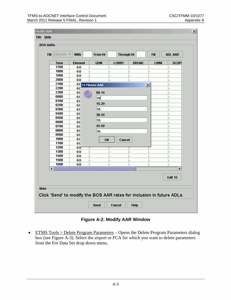
TFMS-to-AOCNET Interface Control Document CSC/TFMM-10/1077 March 2011 Release 5 FINAL, Revision 1 Appendix A
A-5
Figure A-2. Modify AAR Window
ETMS Tools > Delete Program Parameters – Opens the Delete Program Parameters dialog
box (see Figure A-3). Select the airport or FCA for which you want to delete parameters
from the For Data Set drop down menu.

TFMS-to-AOCNET Interface Control Document CSC/TFMM-10/1077 March 2011 Release 5 FINAL, Revision 1 Appendix A
A-6
Figure A-3. Delete Program Parameters Window

TFMS-to-FSM Interface Control Document CSC/TFMM-10/1077 March 2011 Release 5 FINAL, Revision 1 Appendix B
B-1
Appendix B ADL & FSM Broadcast File Format Specifications
The content of this appendix is contained in a separate file that is represented by the
icon below and is linked to this document. To expand the ADL & FSM Broadcast
File Format Specifications file while viewing the ICD online, place your cursor on
the icon below and “Ctrl+click”. To print the contents of the ADL & FSM Broadcast
File Format Specifications file do one of the following:
Open the ICD, navigate to this page, place the cursor on the icon below and
“Ctrl+click”. This will open the file in Microsoft Word. Use the Microsoft Word
print option.
Open “Windows Explorer” and navigate to the directory containing this ICD.
Right click on the “ADL File Specification v12.4doc” file and select the “Print”
option.
ADL File Specification v12.4.doc

TFMS-to-FSM Interface Control Document CSC/TFMM-10/1077 March 2011 Release 5 FINAL, Revision 1 Appendix C
C-1
Appendix C FSM ADL Parameters Specification
The content of this appendix is contained in a separate file that is represented by the
icon below and is linked to this document. To expand the FSM ADL Parameters
Specification file while viewing the ICD online, place your cursor on the icon below
and “Ctrl+click”. To print the contents of the FSM ADL Parameters Specification
file do one of the following:
Open the ICD, navigate to this page, place the cursor on the icon below and
“Ctrl+click”. This will open the file in Microsoft Word. Use the Microsoft Word
print option.
Open “Windows Explorer” and navigate to the directory containing this ICD.
Right click on the “FSM ADL Parameters Specification v5.4.doc” file and select
the “Print” option.
FSM ADL Parameters Spec v5.4.doc

TFMS-to-FSM Interface Control Document CSC/TFMM-10/1077 March 2011 Release 5 FINAL, Revision 1 Appendix D
D-1
Appendix D CDM Message Protocol
There are four types of CDM message protocols:
General CDM session Protocols
ADL session Protocols
Flight Data Message Protocols
Simplified Substitution Protocols
With the exception of the Flight Data Message Protocols, the FSM interface utilizes
three of the above four message protocols. These protocols are detailed in the CDM
Message Protocol document that is represented by the icon below and is linked to
this document. To expand the CDM Message Protocol file while viewing the ICD
online, place your cursor on the icon below and “Ctrl+click”. To print the contents of
the CDM Message Protocol file, do one of the following:
Open the ICD, navigate to this page, place the cursor on the icon below and
“Ctrl+click”. This will open the file in Microsoft Word. Use the Microsoft Word
print option.
Open “Windows Explorer” and navigate to the directory containing this ICD.
Right click on the “CDM Message Protocol v2.4.doc” file and select the “Print”
option.
CDM Message Protocol v2.4.doc