documentation km10xx - beckhoffthe new terminal modules are fully system-compatible. like the bus...
TRANSCRIPT

Documentation
KM10xx
Terminal Modules with Digital Inputs
3.1.02017-01-23
Version:Date:


Product overview KM10xx
KM10xx 3Version: 3.1.0
Product overview KM10xxKM1002, KM1012 [} 11] - 16 inputs, input filter 3 or 0.2 ms
KM1004, KM1014 [} 13] - 32 inputs, input filter 3 or 0.2 ms
KM1008, KM1018 [} 15] - 64 inputs, input filter 3 or 0.2 ms

Table of contents
KM10xx4 Version: 3.1.0
Table of contents1 Foreword .................................................................................................................................................... 5
1.1 Notes on the documentation........................................................................................................... 51.2 Safety instructions .......................................................................................................................... 61.3 Documentation issue status............................................................................................................ 7
2 Product overview....................................................................................................................................... 82.1 Terminal Modules - System Overview ............................................................................................ 82.2 KM1002, KM1012 ......................................................................................................................... 11
2.2.1 Introduction ...................................................................................................................... 112.2.2 Technical data.................................................................................................................. 12
2.3 KM1004, KM1014 ......................................................................................................................... 132.3.1 Introduction ...................................................................................................................... 132.3.2 Technical data.................................................................................................................. 14
2.4 KM1008, KM1018 ......................................................................................................................... 152.4.1 Introduction ...................................................................................................................... 152.4.2 Technical data.................................................................................................................. 16
2.5 KM connector................................................................................................................................ 162.5.1 Ordering information for KM plug-in connector ................................................................ 162.5.2 Technical Data ................................................................................................................. 17
3 Mounting and wiring ............................................................................................................................... 183.1 Recommended mounting rails ...................................................................................................... 183.2 Dimensions ................................................................................................................................... 183.3 Mounting and demounting - terminals with traction lever unlocking ............................................. 203.4 Mounting and demounting - terminals with front unlocking........................................................... 223.5 Wiring............................................................................................................................................ 243.6 Connection technology ................................................................................................................. 26
4 Access from the user program .............................................................................................................. 274.1 Process image .............................................................................................................................. 27
5 Appendix .................................................................................................................................................. 285.1 Support and Service ..................................................................................................................... 28

Foreword
KM10xx 5Version: 3.1.0
1 Foreword
1.1 Notes on the documentation
Intended audience
This description is only intended for the use of trained specialists in control and automation engineering whoare familiar with the applicable national standards.It is essential that the documentation and the following notes and explanations are followed when installingand commissioning these components.It is the duty of the technical personnel to use the documentation published at the respective time of eachinstallation and commissioning.
The responsible staff must ensure that the application or use of the products described satisfy all therequirements for safety, including all the relevant laws, regulations, guidelines and standards.
Disclaimer
The documentation has been prepared with care. The products described are, however, constantly underdevelopment.
We reserve the right to revise and change the documentation at any time and without prior announcement.
No claims for the modification of products that have already been supplied may be made on the basis of thedata, diagrams and descriptions in this documentation.
Trademarks
Beckhoff®, TwinCAT®, EtherCAT®, Safety over EtherCAT®, TwinSAFE®, XFC® and XTS® are registeredtrademarks of and licensed by Beckhoff Automation GmbH.Other designations used in this publication may be trademarks whose use by third parties for their ownpurposes could violate the rights of the owners.
Patent Pending
The EtherCAT Technology is covered, including but not limited to the following patent applications andpatents: EP1590927, EP1789857, DE102004044764, DE102007017835 with corresponding applications orregistrations in various other countries.
The TwinCAT Technology is covered, including but not limited to the following patent applications andpatents: EP0851348, US6167425 with corresponding applications or registrations in various other countries.
EtherCAT® is registered trademark and patented technology, licensed by Beckhoff Automation GmbH,Germany
Copyright
© Beckhoff Automation GmbH & Co. KG, Germany.The reproduction, distribution and utilization of this document as well as the communication of its contents toothers without express authorization are prohibited.Offenders will be held liable for the payment of damages. All rights reserved in the event of the grant of apatent, utility model or design.

Foreword
KM10xx6 Version: 3.1.0
1.2 Safety instructions
Safety regulations
Please note the following safety instructions and explanations!Product-specific safety instructions can be found on following pages or in the areas mounting, wiring,commissioning etc.
Exclusion of liability
All the components are supplied in particular hardware and software configurations appropriate for theapplication. Modifications to hardware or software configurations other than those described in thedocumentation are not permitted, and nullify the liability of Beckhoff Automation GmbH & Co. KG.
Personnel qualification
This description is only intended for trained specialists in control, automation and drive engineering who arefamiliar with the applicable national standards.
Description of symbols
In this documentation the following symbols are used with an accompanying safety instruction or note. Thesafety instructions must be read carefully and followed without fail!
DANGER
Serious risk of injury!Failure to follow the safety instructions associated with this symbol directly endangers thelife and health of persons.
WARNING
Risk of injury!Failure to follow the safety instructions associated with this symbol endangers the life andhealth of persons.
CAUTION
Personal injuries!Failure to follow the safety instructions associated with this symbol can lead to injuries topersons.
Attention
Damage to the environment or devicesFailure to follow the instructions associated with this symbol can lead to damage to the en-vironment or equipment.
Note
Tip or pointerThis symbol indicates information that contributes to better understanding.

Foreword
KM10xx 7Version: 3.1.0
1.3 Documentation issue statusVersion Comment3.1.0 • Technical data for KM plug connectors updated3.0.0 • Migration
• Structural adjustment• Technical data for KM plug connectors extended
2.0.0 • Notes for mounting and wiring updated• Technical data updated
1.0.2 • Technical data corrected• Pin assignment of KM connector X1 corrected
1.0.1 • Notes for mounting and wiring updated• Technical data updated
1.0.0 • KM1004, KM1014, KM1008 and KM1018 added• Mounting and demounting added• Dimensional drawings added
0.1 First provisional documentation for KM1002 and KM1012
Firmware and hardware versions
DocumentationVersion
Hardware versionKM1002 KM1012 KM1004 KM1014 KM1008 KM1018
3.1.0 09 08 06 06 07 043.0.0 09 08 06 06 07 042.0.0 07 05 04 04 04 021.0.2 04 03 02 02 02 011.0.1 01 01 01 01 01 011.0.0 00 00 00 00 00 000.1 00 00 - - - -
The hardware version is indicated in the serial number printed on the top of the terminal module.
Syntax of the serial number
Structure of the serial number: WW YY FF HH
WW - week of production (calendar week)YY - year of productionFF - firmware version (not applicable for digital modules)HH - hardware version
Example with serial number: 35 05 00 01:
35 - week of production 3505 - year of production 200500 - firmware version 0001 - hardware version 01

Product overview
KM10xx8 Version: 3.1.0
2 Product overview
2.1 Terminal Modules - System Overview
Fig. 1: Bus Terminal Block
Better sensor and actuator functionality makes machines and systems more and more powerful. The BusTerminal reliably meets increased requirements for I/O signals through its modularity and compact design.The existing Beckhoff Bus Terminal system is complemented by the new version of the EMxxxx / KMxxxxTerminal Module with increased packing density. In many areas of application, cost benefits can be realizedthrough lower overall installed size and application-specific signal mix.
The new Terminal Modules are fully system-compatible. Like the Bus Terminals, they are bus-neutral andcan therefore be operated with any Beckhoff Bus Coupler and Bus Terminal Controller. Like the standardBus Terminals, the EM / KM modules are integrated in the I/O system and connected with the internalterminal bus (E-bus / K-bus). Bus Terminals and terminal modules can be combined without restriction.
Plug connector
Like for the Bus Terminals, no tools are required for the wiring. Spring-loaded technology is used, howeverthe connection layer is pluggable (fixed wiring).
Fig. 2: Pluggable connection (fixed wiring)
Product overview
KM10xx 9Version: 3.1.0
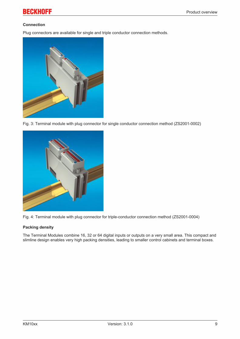
Connection
Plug connectors are available for single and triple conductor connection methods.
Fig. 3: Terminal module with plug connector for single conductor connection method (ZS2001-0002)
Fig. 4: Terminal module with plug connector for triple-conductor connection method (ZS2001-0004)
Packing density
The Terminal Modules combine 16, 32 or 64 digital inputs or outputs on a very small area. This compact andslimline design enables very high packing densities, leading to smaller control cabinets and terminal boxes.

Product overview
KM10xx10 Version: 3.1.0
Fig. 5: Terminal module with 16 channels
Fig. 6: Terminal module with 32 channels
Fig. 7: Terminal module with 64 channels
Product overview
KM10xx 11Version: 3.1.0
2.2 KM1002, KM1012
2.2.1 Introduction
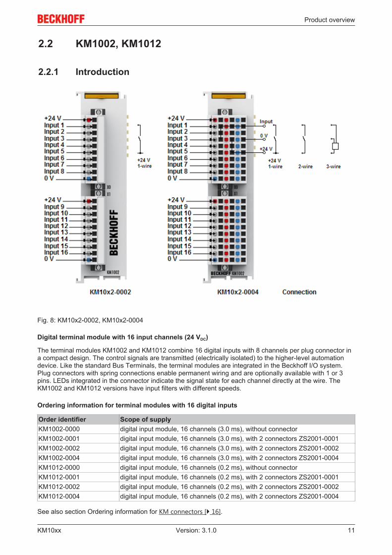
Fig. 8: KM10x2-0002, KM10x2-0004
Digital terminal module with 16 input channels (24 VDC)
The terminal modules KM1002 and KM1012 combine 16 digital inputs with 8 channels per plug connector ina compact design. The control signals are transmitted (electrically isolated) to the higher-level automationdevice. Like the standard Bus Terminals, the terminal modules are integrated in the Beckhoff I/O system.Plug connectors with spring connections enable permanent wiring and are optionally available with 1 or 3pins. LEDs integrated in the connector indicate the signal state for each channel directly at the wire. TheKM1002 and KM1012 versions have input filters with different speeds.
Ordering information for terminal modules with 16 digital inputs
Order identifier Scope of supplyKM1002-0000 digital input module, 16 channels (3.0 ms), without connectorKM1002-0001 digital input module, 16 channels (3.0 ms), with 2 connectors ZS2001-0001KM1002-0002 digital input module, 16 channels (3.0 ms), with 2 connectors ZS2001-0002KM1002-0004 digital input module, 16 channels (3.0 ms), with 2 connectors ZS2001-0004KM1012-0000 digital input module, 16 channels (0.2 ms), without connectorKM1012-0001 digital input module, 16 channels (0.2 ms), with 2 connectors ZS2001-0001KM1012-0002 digital input module, 16 channels (0.2 ms), with 2 connectors ZS2001-0002KM1012-0004 digital input module, 16 channels (0.2 ms), with 2 connectors ZS2001-0004
See also section Ordering information for KM connectors [} 16].

Product overview
KM10xx12 Version: 3.1.0
2.2.2 Technical dataTechnical data KM1002 KM1012Number of inputs 16 (2 x 8)Rated voltage 24 VDC (-15%/+20%)Signal voltage “0” -3 V ... 5 VSignal voltage “1” 15 V ... 30 VInput filter 3.0 ms 0.2 msInput current typically 5 mAPower supply for the electronics via the K-BusCurrent consumption from K-bus typically 3 mAWidth of a bus terminal block Maximum [} 18] 64 standard Bus Terminals or
80 cm(one KM10x2 corresponds to 2 standard BusTerminals here)
Electrical isolation 500 V (K-Bus / signal voltage)Bit width in the input process image 16 bitDimensions with connectors (w x h x d) approx. 26.5mm x 100mm x 71mm (width
aligned: 24mm), see dimensional drawing [} 18]Weight (without connectors) approx. 70 gPermissible ambient temperature range during operation 0°C ... +55°CPermissible ambient temperature range during storage -25°C ... +85°CPermissible relative humidity 95%, no condensationMounting [} 22] on 35 mm mounting rail conforms to EN 60715Vibration/shock resistance conforms to EN 60068-2-6 / EN 60068-2-27EMC immunity / emission conforms to EN 61000-6-2 / EN 61000-6-4Protection class IP20Installation position variableApproval CE

Product overview
KM10xx 13Version: 3.1.0
2.3 KM1004, KM1014
2.3.1 Introduction
Fig. 9: KM10x4-0004
Digital terminal module with 32 input channels (24 VDC)
The terminal modules KM1004 and KM1014 combine 32 digital inputs with 8 channels per plug connector ina compact design. The control signals are transmitted (electrically isolated) to the higher-level automationdevice. Like the standard Bus Terminals, the terminal modules are integrated in the Beckhoff I/O system.Plug connectors with spring connections enable permanent wiring and are optionally available with 1 or 3pins. LEDs integrated in the connector indicate the signal state for each channel directly at the wire. TheKM1004 and KM1014 versions have input filters with different speeds.
Ordering information for terminal modules with 32 digital inputs
Order identifier Scope of supplyKM1004-0000 digital input module, 32 channels (3.0 ms), without connectorKM1004-0001 digital input module, 32 channels (3.0 ms), with 4 connectors ZS2001-0001KM1004-0002 digital input module, 32 channels (3.0 ms), with 4 connectors ZS2001-0002KM1004-0004 digital input module, 32 channels (3.0 ms), with 4 connectors ZS2001-0004KM1014-0000 digital input module, 32 channels (0.2 ms), without connectorKM1014-0001 digital input module, 32 channels (0.2 ms), with 4 connectors ZS2001-0001KM1014-0002 digital input module, 32 channels (0.2 ms), with 4 connectors ZS2001-0002KM1014-0004 digital input module, 32 channels (0.2 ms), with 4 connectors ZS2001-0004
See also section Ordering information for KM connectors [} 16].

Product overview
KM10xx14 Version: 3.1.0
2.3.2 Technical dataTechnical data KM1004 KM1014Number of inputs 32 (4 x 8)Rated voltage 24 VDC (-15%/+20%)Signal voltage “0” -3 V ... 5 VSignal voltage “1” 15 V ... 30 VInput filter 3.0 ms 0.2 msInput current typically 5 mAPower supply for the electronics via the K-BusCurrent consumption from K-bus typically 3 mAWidth of a bus terminal block Maximum [} 18] 64 standard Bus Terminals or
80 cm(one KM10x4 corresponds to 4 standard BusTerminals here)
Electrical isolation 500 V (K-Bus / signal voltage)Bit width in the input process image 32 bitDimensions with connectors (w x h x d) approx. 75mm x 100mm x 55mm (width aligned:
73mm), see dimensional drawing [} 18]Weight (without connectors) approx. 150 gPermissible ambient temperature range during operation 0°C ... +55°CPermissible ambient temperature range during storage -25°C ... +85°CPermissible relative humidity 95%, no condensationMounting [} 22] on 35 mm mounting rail conforms to EN 60715Vibration/shock resistance conforms to EN 60068-2-6 / EN 60068-2-27EMC immunity / emission conforms to EN 61000-6-2 / EN 61000-6-4Protection class IP20Installation position variableApproval CE
Product overview
KM10xx 15Version: 3.1.0
2.4 KM1008, KM1018
2.4.1 Introduction
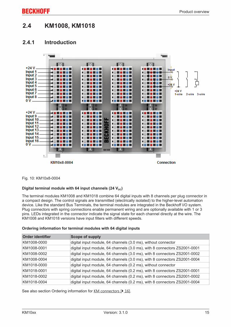
Fig. 10: KM10x8-0004
Digital terminal module with 64 input channels (24 VDC)
The terminal modules KM1008 and KM1018 combine 64 digital inputs with 8 channels per plug connector ina compact design. The control signals are transmitted (electrically isolated) to the higher-level automationdevice. Like the standard Bus Terminals, the terminal modules are integrated in the Beckhoff I/O system.Plug connectors with spring connections enable permanent wiring and are optionally available with 1 or 3pins. LEDs integrated in the connector indicate the signal state for each channel directly at the wire. TheKM1008 and KM1018 versions have input filters with different speeds.
Ordering information for terminal modules with 64 digital inputs
Order identifier Scope of supplyKM1008-0000 digital input module, 64 channels (3.0 ms), without connectorKM1008-0001 digital input module, 64 channels (3.0 ms), with 8 connectors ZS2001-0001KM1008-0002 digital input module, 64 channels (3.0 ms), with 8 connectors ZS2001-0002KM1008-0004 digital input module, 64 channels (3.0 ms), with 8 connectors ZS2001-0004KM1018-0000 digital input module, 64 channels (0.2 ms), without connectorKM1018-0001 digital input module, 64 channels (0.2 ms), with 8 connectors ZS2001-0001KM1018-0002 digital input module, 64 channels (0.2 ms), with 8 connectors ZS2001-0002KM1018-0004 digital input module, 64 channels (0.2 ms), with 8 connectors ZS2001-0004
See also section Ordering information for KM connectors [} 16].

Product overview
KM10xx16 Version: 3.1.0
2.4.2 Technical dataTechnical data KM1008 KM1018Number of inputs 64 (8 x 8)Rated voltage 24 VDC (-15%/+20%)Signal voltage “0” -3 V ... 5 VSignal voltage “1” 15 V ... 30 VInput filter 3.0 ms 0.2 msInput current typically 5 mAPower supply for the electronics via the K-BusCurrent consumption from K-bus typically 3 mAWidth of a bus terminal block Maximum [} 18] 64 standard Bus Terminals or
80 cm(one KM10x8 corresponds to 8 standard BusTerminals here)
Electrical isolation 500 V (K-Bus / signal voltage)Bit width in the input process image 64 bitDimensions with connectors (w x h x d) approx. 123mm x 100mm x 55mm (width aligned:
121mm), see dimensional drawing [} 18]Weight (without connectors) approx. 225 gPermissible ambient temperature range during operation 0°C ... +55°CPermissible ambient temperature range during storage -25°C ... +85°CPermissible relative humidity 95%, no condensationMounting [} 22] on 35 mm mounting rail conforms to EN 60715Vibration/shock resistance conforms to EN 60068-2-6 / EN 60068-2-27EMC immunity / emission conforms to EN 61000-6-2 / EN 61000-6-4Protection class IP20Installation position variableApproval CE
2.5 KM connector
2.5.1 Ordering information for KM plug-in connector
Fig. 11: KM plug-in connector for single-wire connection (ZS2001-0001, ZS2001-0002)
Product overview
KM10xx 17Version: 3.1.0
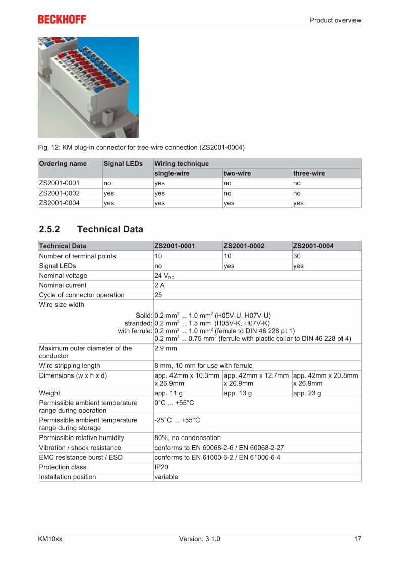
Fig. 12: KM plug-in connector for tree-wire connection (ZS2001-0004)
Ordering name Signal LEDs Wiring techniquesingle-wire two-wire three-wire
ZS2001-0001 no yes no noZS2001-0002 yes yes no noZS2001-0004 yes yes yes yes
2.5.2 Technical DataTechnical Data ZS2001-0001 ZS2001-0002 ZS2001-0004Number of terminal points 10 10 30Signal LEDs no yes yesNominal voltage 24 VDC
Nominal current 2 ACycle of connector operation 25Wire size width
Solid:stranded:
with ferrule:
0.2 mm2 ... 1.0 mm2 (H05V-U, H07V-U)0.2 mm2 ... 1.5 mm (H05V-K, H07V-K)0.2 mm2 ... 1.0 mm2 (ferrule to DIN 46 228 pt 1)0.2 mm2 ... 0.75 mm2 (ferrule with plastic collar to DIN 46 228 pt 4)
Maximum outer diameter of theconductor
2.9 mm
Wire stripping length 8 mm, 10 mm for use with ferruleDimensions (w x h x d) app. 42mm x 10.3mm
x 26.9mmapp. 42mm x 12.7mmx 26.9mm
app. 42mm x 20.8mmx 26.9mm
Weight app. 11 g app. 13 g app. 23 gPermissible ambient temperaturerange during operation
0°C ... +55°C
Permissible ambient temperaturerange during storage
-25°C ... +55°C
Permissible relative humidity 80%, no condensationVibration / shock resistance conforms to EN 60068-2-6 / EN 60068-2-27EMC resistance burst / ESD conforms to EN 61000-6-2 / EN 61000-6-4Protection class IP20Installation position variable

Mounting and wiring
KM10xx18 Version: 3.1.0
3 Mounting and wiring
3.1 Recommended mounting railsTerminal Modules und EtherCAT Modules of KMxxxx and EMxxxx series, same as the terminals of theEL66xx and EL67xx series can be snapped onto the following recommended mounting rails:
• DIN Rail TH 35-7.5 with 1 mm material thickness (according to EN 60715)• DIN Rail TH 35-15 with 1,5 mm material thickness
Note
Pay attention to the material thickness of the DIN RailTerminal Modules und EtherCAT Modules of KMxxxx and EMxxxx series, same as the ter-minals of the EL66xx and EL67xx series does not fit to the DIN Rail TH 35-15 with 2,2 to2,5 mm material thickness (according to EN 60715)!
3.2 Dimensions
KM10x2, KM20x2
Fig. 13: Dimensions KM10x2, KM20x2

Mounting and wiring
KM10xx 19Version: 3.1.0
KM10x4, KM20x4
Fig. 14: Dimensions KM10x4, KM20x4
KM10x8, KM20x8
Fig. 15: Dimensions KM10x8, KM20x8
Width of a Bus Terminal block
Attention
Pay attention to the maximum with and the current consumptionA maximum of 64 Bus Terminals or Bus Terminal Modules may be aligned to a Bus Cou-pler! An overall with of 80 cm must not be exceeded! Also take care that the current con-sumption of the Bus Terminals / Bus Terminal Modules does not overstrain the K-Buspower supply of the Bus Coupler!

Mounting and wiring
KM10xx20 Version: 3.1.0
3.3 Mounting and demounting - terminals with tractionlever unlocking
The terminal modules are fastened to the assembly surface with the aid of a 35 mm mounting rail (e.g.mounting rail TH 35-15).
Note
Fixing of mounting railsThe locking mechanism of the terminals and couplers extends to the profile of the mountingrail. At the installation, the locking mechanism of the components must not come into con-flict with the fixing bolts of the mounting rail. To mount the recommended mounting rails un-der the terminals and couplers, you should use flat mounting connections (e.g. countersunkscrews or blind rivets).
WARNING
Risk of electric shock and damage of device!Bring the bus terminal system into a safe, powered down state before starting installation,disassembly or wiring of the Bus Terminals!
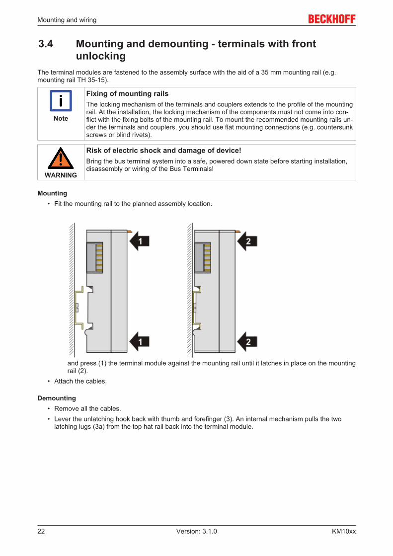
Mounting• Fit the mounting rail to the planned assembly location.
and press (1) the terminal module against the mounting rail until it latches in place on the mountingrail (2).
• Attach the cables.
Demounting• Remove all the cables. Thanks to the KM/EM connector, it is not necessary to remove all the cables
separately for this, but for each KM/EM connector simply undo 2 screws so that you can pull them off(fixed wiring)!
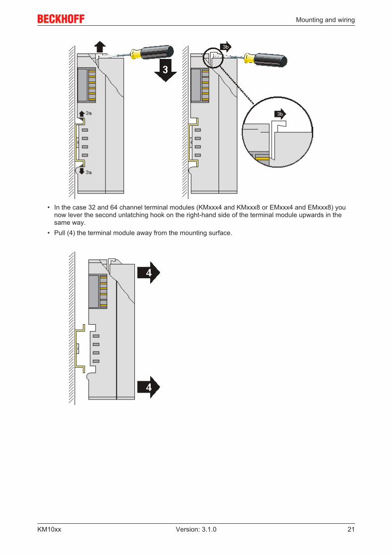
• Lever the unlatching hook on the left-hand side of the terminal module upwards with a screwdriver (3).As you do this
◦ an internal mechanism pulls the two latching lugs (3a) from the top hat rail back into theterminal module,
◦ the unlatching hook moves forwards (3b) and engages
Mounting and wiring
KM10xx 21Version: 3.1.0
• In the case 32 and 64 channel terminal modules (KMxxx4 and KMxxx8 or EMxxx4 and EMxxx8) you
now lever the second unlatching hook on the right-hand side of the terminal module upwards in thesame way.
• Pull (4) the terminal module away from the mounting surface.
Mounting and wiring
KM10xx22 Version: 3.1.0
3.4 Mounting and demounting - terminals with frontunlocking
The terminal modules are fastened to the assembly surface with the aid of a 35 mm mounting rail (e.g.mounting rail TH 35-15).
Note
Fixing of mounting railsThe locking mechanism of the terminals and couplers extends to the profile of the mountingrail. At the installation, the locking mechanism of the components must not come into con-flict with the fixing bolts of the mounting rail. To mount the recommended mounting rails un-der the terminals and couplers, you should use flat mounting connections (e.g. countersunkscrews or blind rivets).
WARNING
Risk of electric shock and damage of device!Bring the bus terminal system into a safe, powered down state before starting installation,disassembly or wiring of the Bus Terminals!
Mounting• Fit the mounting rail to the planned assembly location.
and press (1) the terminal module against the mounting rail until it latches in place on the mountingrail (2).
• Attach the cables.
Demounting• Remove all the cables.• Lever the unlatching hook back with thumb and forefinger (3). An internal mechanism pulls the two
latching lugs (3a) from the top hat rail back into the terminal module.

Mounting and wiring
KM10xx 23Version: 3.1.0
• Pull (4) the terminal module away from the mounting surface. Avoid canting of the module; you should stabilize the module with the other hand, if required.
Mounting and wiring
KM10xx24 Version: 3.1.0
3.5 Wiring
WARNING
Risk of electric shock and damage of device!Bring the bus terminal system into a safe, powered down state before starting installation,disassembly or wiring of the Bus Terminals!
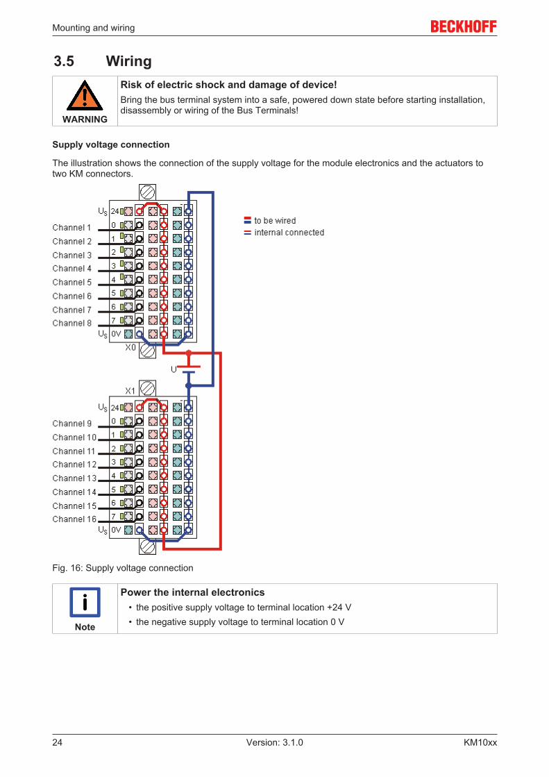
Supply voltage connection
The illustration shows the connection of the supply voltage for the module electronics and the actuators totwo KM connectors.
Fig. 16: Supply voltage connection
Note
Power the internal electronics• the positive supply voltage to terminal location +24 V• the negative supply voltage to terminal location 0 V
Mounting and wiring
KM10xx 25Version: 3.1.0
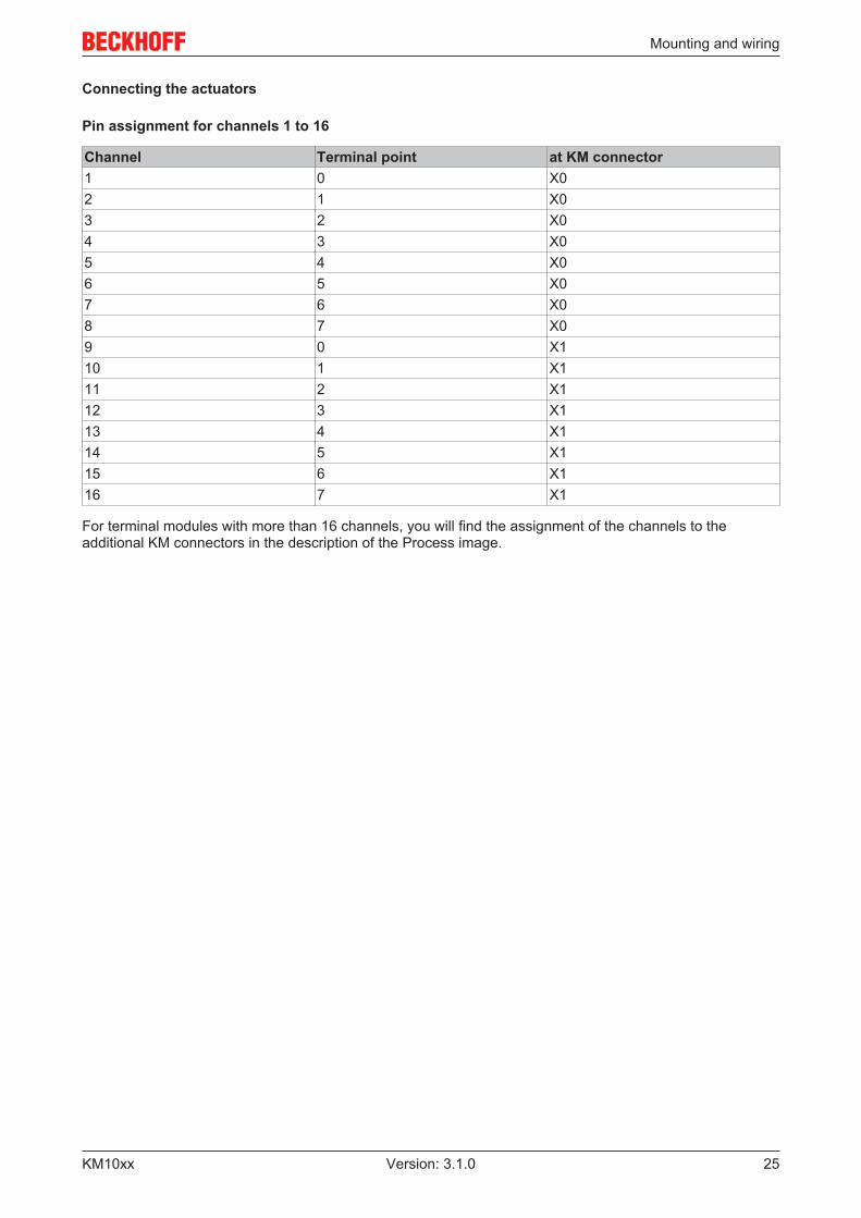
Connecting the actuators
Pin assignment for channels 1 to 16
Channel Terminal point at KM connector1 0 X02 1 X03 2 X04 3 X05 4 X06 5 X07 6 X08 7 X09 0 X110 1 X111 2 X112 3 X113 4 X114 5 X115 6 X116 7 X1
For terminal modules with more than 16 channels, you will find the assignment of the channels to theadditional KM connectors in the description of the Process image.
Mounting and wiring
KM10xx26 Version: 3.1.0
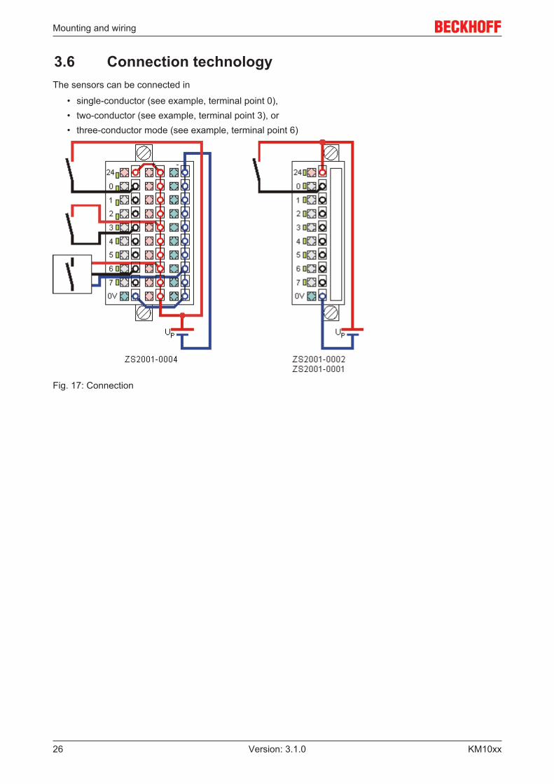
3.6 Connection technologyThe sensors can be connected in
• single-conductor (see example, terminal point 0),• two-conductor (see example, terminal point 3), or• three-conductor mode (see example, terminal point 6)
Fig. 17: Connection

Access from the user program
KM10xx 27Version: 3.1.0
4 Access from the user program
4.1 Process image
KM1002, KM1012
The process image of the KM1002/KM1012 terminal modules consists of 2 bytes of input data.
Byte offset Format Input data KM connector0 Byte DataIN (channel 1 to 8) X01 Byte DataIN (channel 9 to 16) X1
KM1004, KM1014
The process image of the KM1004/KM1014 terminal modules consists of 4 bytes of input data.
Byte offset Format Input data KM connector0 Byte DataIN (channel 1 to 8) X01 Byte DataIN (channel 9 to 16) X12 Byte DataIN (channel 17 to 24) X23 Byte DataIN (channel 25 to 32) X3
KM1008, KM1018
The process image of the KM1008/KM1018 terminal modules consists of 8 bytes of input data.
Byte offset Format Input data KM connector0 Byte DataIN (channel 1 to 8) X01 Byte DataIN (channel 9 to 16) X12 Byte DataIN (channel 17 to 24) X23 Byte DataIN (channel 25 to 32) X34 Byte DataIN (channel 33 to 40) X45 Byte DataIN (channel 41 to 48) X56 Byte DataIN (channel 49 to 56) X67 Byte DataIN (channel 57 to 64) X7

Appendix
KM10xx28 Version: 3.1.0
5 Appendix
5.1 Support and ServiceBeckhoff and their partners around the world offer comprehensive support and service, making available fastand competent assistance with all questions related to Beckhoff products and system solutions.
Beckhoff's branch offices and representatives
Please contact your Beckhoff branch office or representative for local support and service on Beckhoffproducts!
The addresses of Beckhoff's branch offices and representatives round the world can be found on her internetpages:http://www.beckhoff.com
You will also find further documentation for Beckhoff components there.
Beckhoff Headquarters
Beckhoff Automation GmbH & Co. KG
Huelshorstweg 2033415 VerlGermany
Phone: +49(0)5246/963-0Fax: +49(0)5246/963-198e-mail: [email protected]
Beckhoff Support
Support offers you comprehensive technical assistance, helping you not only with the application ofindividual Beckhoff products, but also with other, wide-ranging services:
• support• design, programming and commissioning of complex automation systems• and extensive training program for Beckhoff system components
Hotline: +49(0)5246/963-157Fax: +49(0)5246/963-9157e-mail: [email protected]
Beckhoff Service
The Beckhoff Service Center supports you in all matters of after-sales service:
• on-site service• repair service• spare parts service• hotline service
Hotline: +49(0)5246/963-460Fax: +49(0)5246/963-479e-mail: [email protected]

List of illustrations
KM10xx 29Version: 3.1.0
List of illustrationsFig. 1 Bus Terminal Block...................................................................................................................... 8Fig. 2 Pluggable connection (fixed wiring) ............................................................................................. 8Fig. 3 Terminal module with plug connector for single conductor connection method (ZS2001-0002) . 9Fig. 4 Terminal module with plug connector for triple-conductor connection method (ZS2001-0004) .. 9Fig. 5 Terminal module with 16 channels .............................................................................................. 10Fig. 6 Terminal module with 32 channels .............................................................................................. 10Fig. 7 Terminal module with 64 channels .............................................................................................. 10Fig. 8 KM10x2-0002, KM10x2-0004 ...................................................................................................... 11Fig. 9 KM10x4-0004 .............................................................................................................................. 13Fig. 10 KM10x8-0004 .............................................................................................................................. 15Fig. 11 KM plug-in connector for single-wire connection (ZS2001-0001, ZS2001-0002) ........................ 16Fig. 12 KM plug-in connector for tree-wire connection (ZS2001-0004) ................................................... 17Fig. 13 Dimensions KM10x2, KM20x2..................................................................................................... 18Fig. 14 Dimensions KM10x4, KM20x4..................................................................................................... 19Fig. 15 Dimensions KM10x8, KM20x8..................................................................................................... 19Fig. 16 Supply voltage connection........................................................................................................... 24Fig. 17 Connection................................................................................................................................... 26