documentation to the database project ‘music store’ · pdf filedocumentation to...
TRANSCRIPT
Documentation to the Database Project ‘MUSIC STORE’
Yuri Sublaban [email protected] 9578730 Student IK
Martijn van Eimeren M.A.vanEimeren@ student.uva.nl 0473111 Student IK
Timm Kapferer [email protected] 0125326 Student IK
Brian Baal brian.daal@ student.uva.nl 0157481 Student IK

DATABASE PROJECT ‘MUSIC STORE’
2
Table of contents
1. Abstract
2. Introduction
3. Related Research
4. Architecture
5. Functionality Design
6. Implementation Approach
7. Conclusion
8. References
Appendix
1. Organizational Issues
2. Technologies
3. User Manual
4. Test Scenarios
DATABASE PROJECT ‘MUSIC STORE’
3
1. ABSTRACT
This document presents the issues of the database project entitled ’Music store’. Its aim is to formally describe the phases of the design and development. These phases are categorized into 3 main steps: Database, Application and Graphic User Interface. The Music store is an order by phone- Company. The platform is a SQL database with JDBC support. Application and the GUI are developed in Java using JDBC. The result is a database which enables the clerks and the manager of the Music store to manage the information of customer, artists, albums and songs.
2. INTRODUCTION
The aim of this project is the development of a sample centralized relational Music store application. This application has to store information of customers and artists with their products. In this context the functionality is to update, remove and insert records for the different entities. The database is built for the clerks and the managers from a Music store. Customers are ordering by phone or by email. The clerk of the databases must be able to fulfill the wishes of the customer. These wishes include finding the right album and ordering this album.
This project team decided to implement the core functionality first and later to attach additional functions. The Core functionality is:
• Add, delete and update Customer information • Add, delete, and update information about the album, artists and songs. • Insert new and change a customer order. A customer order exists out of the
customer information and the product information’s.
This decision is made because the short time schedule of four weeks and the not experienced java abilities of the team. The team’s minimum target is to show these core functionalities in a user friendly Graphic User Interface (GUI). This consideration is taken into the architecture of the database, which tries to ensure a built on architecture. Additional functionality has to be integrated in an easy way. Examples of these additional features can be:
• Overviews of the entities Customer, Product and Order. • Error checking of the application. • Possibility to arrange the customer information for the manager of the
Music store. This enables the manager to get a greater knowledge about the customers.
• The customer can choose his/her favorite songs. These songs will be produced by the Music store on an own CD.

DATABASE PROJECT ‘MUSIC STORE’
4
This documentation describes the development of this project and it includes: Architecture (the structure of the database), Implementation approach (the main parts: Database, Application and GUI), Functionality design (the structure of the program), GUI (Explanation and test scenarios), Technologies, Literature and Appendix. 3. RELATED RESEARCH
In this part of the paper we will discus some of the work that was presented during this course. We also made a small literature study about some subjects that relates to the project in question. The main purpose of this part is to show the relation between this project and the subjects that are being researched in the field. It’s an expansion of the project in question where we aim to relate them in a greater whole. We will not go into the technical details about the subjects discussed here. We want to merely show the aspect worth considering if we would think about the project as being part of a greater totality.
As mentioned above our assignment was to make a simple application in order for customers to order CD’s and DVD’s. As you may have noticed we made the interface using java. This was a simple and straight forward approach. If we consider some of the subjects described in the lectures of this course like XML we notice that the application may well be ported to the web using XML. Nowadays most application, like the one we modeled here is being delivered via the web. So it’s worth considering the aspect of web enabled solutions. Besides the use of XML one can also use other technologies like PHP and ASP etc to port these type of application to the web.
When considering these solutions and the potential to expand the application and considering it as being part of a greater system, one must also consider other aspects that relates to the problems one will face when dealing with these types of systems.
One can consider the fact that the type of organization we are dealing with can be thought of as being a “virtual” type of organization. One can extend the idea of this single organization to be related to other organization in the field as well. These can be organizations that deliver the different products to this organization. In this specific case we modeled only one aspect of this organization which deals with the ordering of cd’s and dvd’s by customers. If we were to consider this application to be a sub-part of other application in this organization, than we could apply some of the aspects that are presented in Afsarmanesh, et al. (1998). The main purpose is the interrelation and information exchange between the different systems.
In Afsarmanesh, et al.(1998) they present the WaterNET system were the main purpose of the system was to improve information sharing with (the) other (sub)system(s) within the company. The case confronted here is a system where all the sub-systems work independently and most of them are heterogeneous by nature. They present us with a solution to interrelate these systems with each other so that

DATABASE PROJECT ‘MUSIC STORE’
5
the information sharing is achieved between these systems. They show the implementation of the federated databases and how this approach can help to solve the problems they are facing when trying to interrelate these different systems. Later on in the paper they present us with two different implementation approaches, one which is based on the PEER federated information management system and the other which is extended with the adapter framework. This adapter framework provides the so much needed flexibility within the systems, so that components can be added and removed from the system. Their approach also emphasis that their will be no need for a centralized database and thus also solves the problems of data replication.
If we consider to the solution Afsarmanesh, et al. (1998) presents us, we can imagine how the interrelation between the different organizations that delivers products to our organization can be interrelated to each other. For if the Music Store application was to be considered as being part of greater totality, the need of information sharing between the different systems may rise.
Besides this solution to interrelate the different systems with each other we are also presented other aspects about information access and visibility levels for virtual enterprises in Frenkel, et al. (2000). Frenkel, et al. (2000) presents us an aspect that would be worth considering when dealing with virtual organizations that are related to other companies. The main subject he discus is what information to make available to the other enterprises and how they are allowed to see it.
Concluding we can note that there are a lot of aspects worth considering when developing a simple application as this one. It may be a small system but if we look at the whole picture we can notice that most organizations consist of these “small applications”. And it’s the interrelation between these small systems that presents a lot of hardships. Most of the organization would choose for a centralized approach where all the data is gathered into one big database, but with the solutions we are presented here one can take a generic approach to the problem in question. 4. ARCHITECTURE
This section illustrates the architecture of the database using an Entity Relationship Diagram (ERD) and a Relational Schema Definition. The ERD shows the overall structure and communication in the database. The Relational Schema Definition describes the tables to be created in the database. 4.1 ERD
The Entity Relationship Diagram (Figure 1) describes the entities Customer, Product, Artist, Track and Customerorder. Each entity has a primary key (underlined in Figure 1). A product (album) has the media type CD, DVD, Tape or Records and consists out of tracks (songs). The attributes of each entity are given in a circle with the primary keys underlined. The relationships such as orders, lists, produces and media tracks connect the entities in a structured and simple manner.

DATABASE PROJECT ‘MUSIC STORE’
6
Figure 1: ERD of the Music store Database Mapping cardinalities are illustrated as arrows and explained below:
• Many products can have many artists. • One product can have many tracks. • One customer order can have many products. • One customer can have many customer orders.

DATABASE PROJECT ‘MUSIC STORE’
7
As stated in the introduction this team chose for the straightforward structure to
simplify the implementation. The ERD presents the main directives the project is following throughout the development. 4.2 Relational Table definition
This definition is the base for creating the tables in the database. In general it gives the same information as the ERD but in a more specific way.

DATABASE PROJECT ‘MUSIC STORE’
8
Figure 2: Relational Table Definition 4. FUNCTIONALITY DESIGN
The diagram as pictured in the technical design schedule is mostly for serving to provide a ‘high level’ overview of the application structure. Therefore not every single class or attribute may be present in the diagram. Classes and other items that don’t specifically clarify or illustrate anything “out of the ordinary” have been omitted for extra clarity.
Figure 3: technical design Presentation of the program structure
The program structure as we have decided upon at this moment consists of a set of classes (separately defined in the “class definition file”). And the ‘core’ program structure which consists of a main routine. That holds a JFrame class. This (extended) JFrame object holds aside from the separate form objects & menu’s also the calls to the specific (separate) classes and sub-windows/screens. As well as the objects that are needed to maintain and utilize the database and it’s connection. So the management of the database is kept relatively central in the ‘main’ class of the JFrame Wnd. This should prevent locking problems in case a separate function or class doesn’t execute properly. Whenever a class is called or defined a Connection pointer or reference is passed of to the constructor of that particular object so it can manipulate the database for as long as needed and then simply leave the Connection pointer to the garbage collection.

DATABASE PROJECT ‘MUSIC STORE’
9
6. IMPLEMENTATION APPROACH The implementation consists of the three following main components. 6.1 Music store database
The database was provided by the University of Amsterdam. Database administrators were the assistants of the course. The database has JDBC (Java database connectivity) support. The creation of the tables is made by using the query language SQL. Two examples of the code are included below:
CREATE TABLE TRACK ( TRACKTITLE VARCHAR(100), LENGTH INTEGER, PRIMARY KEY (TRACKTITLE) )
CREATE TABLE CUSTOMER ( CUSTOMERID SERIAL, CITY VARCHAR(30), STREET VARCHAR(30), ZIP VARCHAR(30), FIRSTNAME VARCHAR(30), LASTNAME VARCHAR(30), PHONENUMBER INTEGER, EMAIL VARCHAR(50), PREFFEREDGENRE VARCHAR(30), PRIMARY KEY (CUSTOMERID) )
While creating the tables using the Relational schema definition of section 2.2
for each attribute a variable type is given. Except of the attribute TRACKTITLE of table TRACK all other primary keys where generated as data type SERIAL. This means that for each entry of the database an ID is generated automatically. Reason is to ensure that all ids do not have to be generated by the clerks or manager of the Music store as well as an overall stability. 6.2 Music store application
The application is implemented in Java. JDBC is used to connect to the database
and to obtain the associated information. As an example the code to connect to the database is given in Figure 4. JDBC is also used to call SQL queries into the java code. This makes possible to access the database and create, update or view the data stored. Further explanation are provided in section 4 related to the Functionality design.

DATABASE PROJECT ‘MUSIC STORE’
10
try{ Class.forName("com.mysql.jdbc.Driver"); myConnection=DriverManager.getConnection( "jdbc:mysql://123.156.5.73/dbpc-t6","username", "password" ); } catch(Exception e){ System.out.println("Failed to get connection"); e.printStackTrace(); } }
Figure 4: Connection code to the database
6.3 Music store graphic user interface (GUI)
The GUI is generated in Java. Therefore the Java package Java.swing was most used. The Java enables to create the window design as shown as shown in the User Manual. A further explanation of the GUI is illustrated in the User Manual and the Test Scenarios. 7. CONCLUSION
As stated in the introduction the minimum target at the beginning of this project was to show the core functionalities in a user friendly GUI. During the implementation the team reached their limits and succeeded in replacing these limits several times. This section will illustrate what the team reached and which problems occurred during the project. It will describe where the planning was realistic and will also give recommendations for similar or further projects.
The core functionality was reached in the following parts. It is possible to insert
a new customer, change the details of a customer and delete a customer. Also the product part is implemented in the same way. A new product can be inserted, changed and deleted. Furthermore the order section is completely implemented. It is possible to fill in one order for several products. This order also can be changed and deleted.
The team did not succeed in implementing all the artist and song functionality
which was planned. Reasons for that are the lack of experience and time as well as the wish to implement additional features in order to enrich the application from a different angle.
The additional features that were reached are creating the overviews of the
entities, and error checking. These offer extra functionality to the clerks and the managers of the Music Store. The team was intent on achieving a well designed ‘Insert new order’ window. Through this challenge a window was designed in a way that enables the user to simultaneously select products and customer, and view the details of the selected, in the same window. The application also provides error checking: this means every input is tested of validity.

DATABASE PROJECT ‘MUSIC STORE’
11
The GUI passed well 2 test scenarios. The team created an easy to use
application with self-guiding windows. During the process the team was faced with challenges in the problem of data update. If data is changed the view window must be closed and opened again to see this change. Through research and discussion this problem was solved in implementing a refresh possibility in the view windows.
Further development of the project is possible as stated in the introduction in
additional features. Due to the problems described in the paragraphs above and the short amount of time, it was not possible to implement all additional features. It will be interesting to implement more functions in arranging the information of the songs and the artists of the products. The built-on architecture that was used supports future developments.
It is advised to similar projects to consider the problems stated in this
conclusion. Such projects should plan from the start how to surpass the limitations of their programming language. This implies a better knowledge of Java programming itself. They should also follow a strict responsibility policy like in this team. A well planned teamwork is crucial for facing problems during the process.
8. REFERENCES
1. Afsarmanesh, H., Benabdelkader, A. and Hertzberger, L.O. (1998), A Flexible Approach to Information Sharing in Water Industries. In Proceedings of the International Conference On Information Technology, CIT'98, pages 135-142, Bhubaneswar, India, December 1998.
2. Arlow, Jim and Ila Neustadt (2002), UML and the Unified Process, Addison Wesley 3. Deitel and Deitel (2002), Java How to Program, 4th Ed, Prentice Hall 4. Deitel and Deitel (2002), Advanced Java How to program, Prentice Hall - Advanced Java 2
Platform (Deitel, JDK 1.3, J2EE 1.2). 5. Frenkel, A., Afsarmanesh, H., Garita, C. and Hertzberger, L.O. (2000), Supporting
information access rights and visibility levels in virtual enterprises… 6. Horstmann, Cay and Cornell, Gary, (2004), Core Java(TM) 2, Volume II--Advanced Features
(7th Edition). 7. Guevara-Masis, V., Afsarmanesh, H. and Hertzberger, L.O. (2004), Ontology-based automatic
data structure generation for collaborative networks 8. Silberschatz, Korth, and Sudarshan, (2002), Database System Concepts, 4th ed: McGraw-
Hill.

DATABASE PROJECT ‘MUSIC STORE’
12
Appendix 1. Technologies
• MySQL Query browser: This SQL tool enables an easy way to change the
database without an application.
• Netbeans IDE: A Java editor.
• Microsoft Visio: Designing the structure of the project.
2. Organizational issues
This project is part of the course ‘Project databasetoepassingen’ given on the University of Amsterdam. Lecturers of this course are Dr. Hamideh Afsarmanesh (coordinator) and Dr. Irina Neaga. The assistants are Mr. Gerben de Vries and Mr. Reinier Zevenhuijzen. The class is divided into groups by 4 or 5 students. Each team has to develop a different project. 3. User Manual 3.1 Description
The GUI consists of a Menu showing the following main categories: Menu, Customer, Product, Order, Settings and Help. The music store clerk can view, delete, add or change entries in customer, order and product. The categories Menu, Settings and Help are additional functions. ‘Menu’ enables to exit the application. ‘Settings’ shows the status of the connection. Help gives additional support. Below a illustration of the Menu items Customer, Product and Order is presented. Through the different sub items new windows will open showing the information it …. 3.2 Menu item Customer
This item includes sub-items ‘View All Customer’, ‘Insert New Customer’, ‘Change Customer’ and ‘Delete Customer’. Figure 5 shows a list of all customers (View All Customer). They are grouped alphabetically to facilitate a convenient search. All attributes of the customers are listed. It is possible to select one and delete or change the customer details. The ‘Refresh button’ is necessary to update the view after a change is made. For adding a new customer the clerk has to choose the sub-item ‘Add customer’ which opens a new window. The same is applies to the other sub-items.

DATABASE PROJECT ‘MUSIC STORE’
13
Figure 5: The menu item ‘View All Customer’ 3.3 Menu item Product
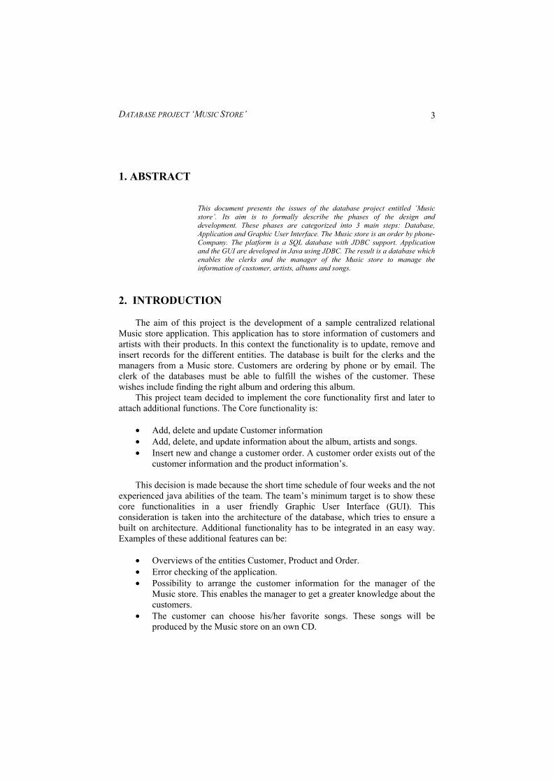
‘Product’ has the same overall structure as the ‘Customer’. This includes ‘View All Products’, ‘Insert New Product’, ‘Change Product Details’ and ‘Delete Product’ Figure 6 shows a screenshot of ‘View All Products’.
DATABASE PROJECT ‘MUSIC STORE’
14
Figure 6: The menu item ‘View All Products’ 3.4 Menu item Order Figure 7 shows the menu item ‘Insert New Order’. The clerk can choose a customer id and several products. It is possible to see the generated order details below.

DATABASE PROJECT ‘MUSIC STORE’
15
Figure 7: The menu item ‘Insert New Order’ 4. Test Scenarios
Presenting two test scenarios will test and explain the usage of the database. These scenarios are chosen to create a real world situation. First there will be a short description of the situation. Second one will follow the steps of the clerk / manager to solve the situation. This will be described using the USE CASE format from Jim Arlow et al (2002). Test scenario 1: A new customer is calling the Music store. He/She asks for the price and availability of the album “Holly goes Hollywood”. After getting that information he/she wants to order this album. For this Scenario three use cases have to be performed by the clerk:
DATABASE PROJECT ‘MUSIC STORE’
16
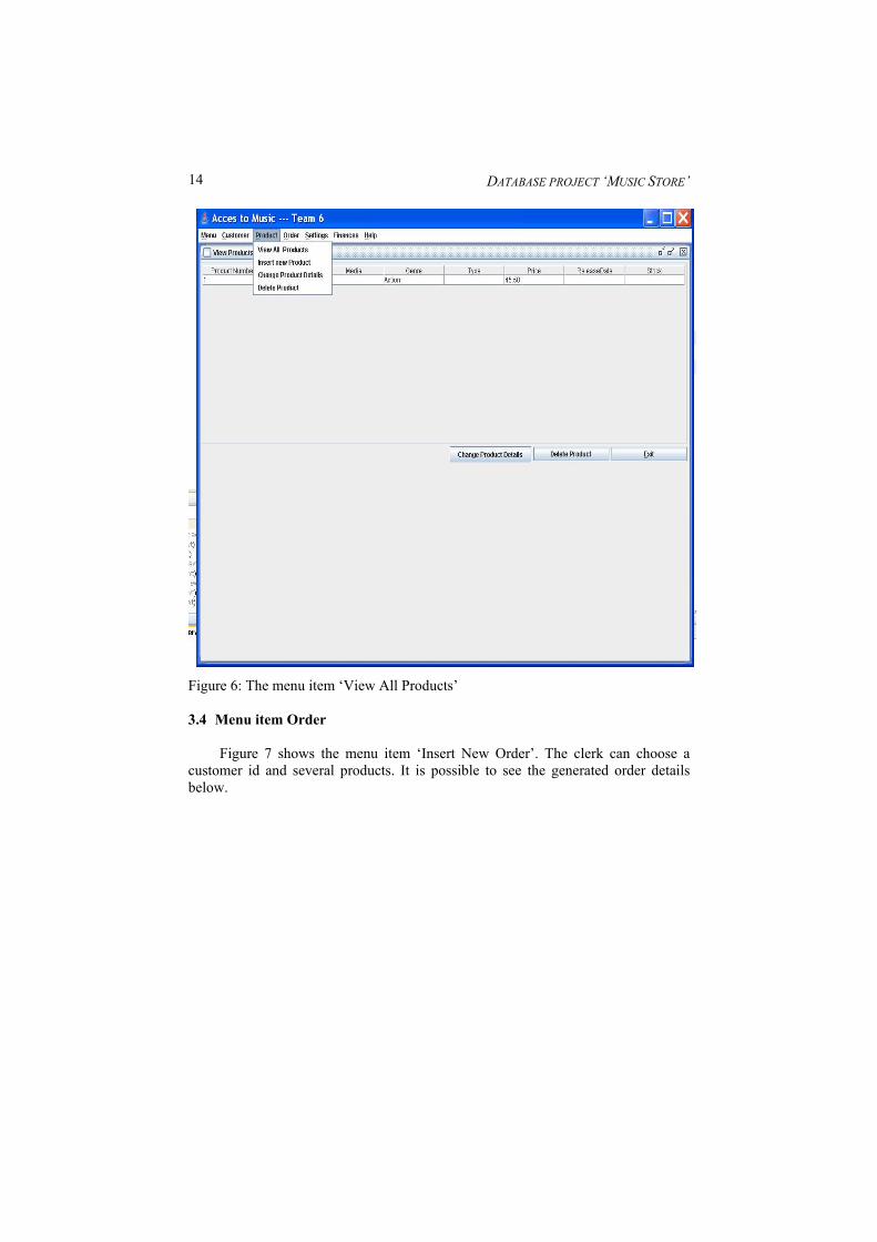
Use Case 1: View Products Preconditions: The clerk is logged on to the application. Flow of events:
1. The clerk selects the menu item ‘View Products’ 2. The application shows a list of all products 3. The clerk scrolls to the album ‘Holly goes Hollywood’ and reads the
information about availability and price to the customer. Postconditions: The clerk knows the ProductID of the album ‘Holly goes Hollywood’ Use Case 2: Add Customer Preconditions: The clerk is logged on to the application. Flow of events:
1. The clerk selects the menu item ‘Add Customer’ 2. The clerk enters the customerdetails 3. The application is generating a new Customer
Postconditions: The clerk knows the CustomerID of the new Customer. Use Case 3: Order Products Preconditions: The clerk is logged on to the application, has the ProductID of the album ‘Holly goes Hollywood’ and the CustomerID of the Customer Flow of events:
1. The clerk opens the menu item ‘insert new order’. 2. The clerk enters the ProductID. 3. The clerk enters the CustomerID. 4. The application is generating a new order.
Postconditions: --- Test scenario 2 A customer (CustomerID 3) wants tobe removed out of the database. For this Scenario one use case has to be performed by the clerk: Use Case: Delete Customer Preconditions: The clerk is logged on to the application and has the CustomerID of the Customer.

DATABASE PROJECT ‘MUSIC STORE’
17
Flow of events: 1. The clerk opens the menu item ‘delete customer’ 2. The clerk enters the CustomerID and confirms. 3. The application deletes the customer in the database.
Postconditions: ---